
Subscribe to Our Youtube Channel
Related Manuals for WAGO 767-1501


Summary of Contents for WAGO 767-1501
- Page 1 Quick-Start Guide WAGO SPEEDWAY 767 CANopen, 8 DI, 24 V DC 767-1501 Fieldbus Coupler Version 2.0.0...
-
Page 2: Introduction
Additional Support The Seminar and Training department offers useful seminars to support you in the use of WAGO products. For more information, visit our website or call +49 571 887-327, or send an e-mail to training@wago.com. Trademarks We wish to point out that the software and hardware terms as well as the trademarks of companies used and/or mentioned in the present manual are generally protected by trademark or patent. -
Page 3: Table Of Contents
Installation....................25 Starting Up the Fieldbus Coupler............30 Operation....................31 System Update.................... 36 Adding the DTM System Update............37 Go online to 767 Nodes using Update DTM .......... 38 Updating the 767 Components..............39 WAGO-SPEEDWAY 767 Fieldbus Coupler for CANopen... -
Page 4: Safety
NOTICE Supply layout! In addition to these operating instructions, you will need the "WAGO SPEEDWAY 767, System Description and Information" manual, which can be downloaded at www.wago.com. There you will find information regarding supply layout, etc. -
Page 5: Explanation Of Symbols
Indicates a possible hazard that could lead to equipment damage if not avoided. NOTICE Warning of damage to equipment from electrostatic discharge Indicates a possible hazard that could lead to equipment damage if not avoided. WAGO-SPEEDWAY 767 Fieldbus Coupler for CANopen... - Page 6 Indicates possible malfunction, which does not lead to equipment damage if it is not avoided. Information Reference to additional information Indicates other sources of information which are not an integral part of this documentation, such as the Internet. WAGO-SPEEDWAY 767 Fieldbus Coupler for CANopen...
-
Page 7: Validity Of This Quick-Start Guide
Safety Validity of This Quick-Start Guide These operating instructions are only applicable to the positive-switching WAGO SPEEDWAY 767 Series fieldbus coupler, item number 767-1501. Use in Compliance with Underlying Provisions The CANopen fieldbus coupler provides digital process data from digital and analog I/O modules. -
Page 8: Basic Safety Information
Series component. Neither of these values shall exceed 4A since an increase in current causes the contacts to overheat and damages the 767 Series components. Information regarding the power demand of each 767 Series component can be found in the corresponding data sheet, which is available from www.wago.com. NOTICE Exposed connections! If connections have not been closed with protective covers, liquid or dirt can penetrate the fieldbus coupler and ruin it. -
Page 9: Safety Equipment
EMC-suitable installations. • For the power supply and for the S-BUS, use only pre-assembled WAGO system cables, so the specified characteristics of the technical data can be achieved. •... -
Page 10: Technical Condition Of The 767 Components
Safety Technical Condition of the 767 Components If any change is made to the 767 Series components or software and firmware without the written approval of WAGO Kontakttechnik GmbH & Co. KG, all liability claims are nullified. Notes on Operation... -
Page 11: Description
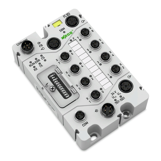
Description Description This quick-start guide describes the process of starting up the 767-1501 Fieldbus Coupler on a 758-870/000-012 Industrial PC. I/O modules are connected to the fieldbus coupler via the S-BUS (system bus). Start-up is completed in two steps. In the first step, the network is configured using the PLC configuration inside CoDeSys 2.3. - Page 12 (A coded), M12 plug, right angle, Fitted on both ends 0.2m Fieldbus coupler for FC, 8DI, 24 V DC (8xM8) 767-1501 CANopen Digital output module 8 DO, 24 V DC 0,5 A (8 x M8) 767-4801 Industrial PC with 758-870/000-112...
-
Page 13: Connection
Then tighten the connector by hand when power is switched off. Using mechanical means to tighten it may strip the threads. In such a case, the fieldbus coupler is to be replaced. Tightening torques for the connectors: 0.6 Nm WAGO-SPEEDWAY 767 Fieldbus Coupler for CANopen... - Page 14 WAGOframe power supply supply Debug Supply voltage (M12 connectors, A coded, 4 poles): Power supply feed-in for logic circuits and outputs is provided via separate contacts. Connection Contact Description 24VDC 24VDC U 0V U WAGO-SPEEDWAY 767 Fieldbus Coupler for CANopen...
- Page 15 - Data + Data 0VDC Connecting thread Shielded The USB Speedway device driver is part of the installation programs of the "WAGOframe" application. For more information, see Chapter Fehler! Verweisquelle konnte nicht gefunden werden.. WAGO-SPEEDWAY 767 Fieldbus Coupler for CANopen...
- Page 16 Please note that the combined power consumption of all connected sensors is not to exceed 400mA. The distribution of power among the existing connections is depending on the individual power requirements of the sensors. WAGO-SPEEDWAY 767 Fieldbus Coupler for CANopen...
-
Page 17: Setting The Canopen Station Address
Close the cover and screw it securely in place to maintain degree of protection IP 67. Note The CANopen station address is only active when the fieldbus coupler is connected to the power supply. WAGO-SPEEDWAY 767 Fieldbus Coupler for CANopen... - Page 18 767-1501 DIP switch set for station address 52 During operation, the device address can be set via the CANopen object or via WAGOframe (see operating instructions for 767-1501). Restart the fieldbus coupler to activate the new station address. WAGO-SPEEDWAY 767...
-
Page 19: Setting The Baud Rate
8| BR 6| 2 6| 2 5| 2 5| 2 4| 2 4| 2 3| 2 3| 2 2| 2 2| 2 1| 2 1| 2 767-1501 DIP switches set for a 500kbit/s baud rated WAGO-SPEEDWAY 767 Fieldbus Coupler for CANopen... -
Page 20: Plc Configuration In Codesys
"Support for DSP301 V4.01 and DSP306" is selected in the CAN parameters of the master: 1. Right-click on "CanMaster" and select "Append Subelement" from the context menu. Select "WAGO 767-1501." WAGO-SPEEDWAY 767 Fieldbus Coupler for CANopen... - Page 21 2. "Node ID," "Device Type" and "Node Guarding" must be configured in the "CAN Parameter" dialog box. 3. In the "CAN Module Selection" dialog box, select the I/O modules that correspond to the hardware being used. WAGO-SPEEDWAY 767 Fieldbus Coupler for CANopen...
- Page 22 PLC Configuration in CoDeSys 4. You can now assign the symbolic names for the input and output data in the configuration tree. These names can then be used throughout the project to access the inputs and outputs. WAGO-SPEEDWAY 767 Fieldbus Coupler for CANopen...
-
Page 23: Plc Program
The following test program shows easy access to the process data of the connected slave. The status of the first digital input of 767-1501 will be scanned, and its negated value will be assigned to the first output of the 767-4801. -
Page 24: Wagoframe
A "Device Type Manager"(DTM) groups all the setting options for a field device (including graphic interfaces) into a single program that is executed in an FDT/DTM frame application. The specification makes a distinction between device DTMs, communication DTMs and gateway DTMs. WAGO-SPEEDWAY 767 Fieldbus Coupler for CANopen... -
Page 25: Installation
When performing an installation from the file system switch to the directory "~/WAGOframe CD-ROM_v3.0.0" and open the file "Deutsch_main.htm". To install all the required components, select "Series 767 + WAGOframe". WAGO-SPEEDWAY 767 Fieldbus Coupler for CANopen... - Page 26 "CoDeSys 3" setup. Any USB driver that is already installed will then be updated. If an older version of "WAGOframe" is installed, this must first be de-installed with the installation routine. The same applies to DTMs. WAGO-SPEEDWAY 767 Fieldbus Coupler for CANopen...
- Page 27 Continue by clicking [OK]. Continue by clicking [Next >]. Read the Terms of Use for the WAGO USB driver before selecting "I accept...". Confirm this selection. Then click on [Next]. WAGO-SPEEDWAY 767 Fieldbus Coupler for CANopen...
- Page 28 Check your personal settings. Continue by clicking [Next >]. Select the installation path under which the application is to be saved. Start the installation by clicking the [Install] button. Continue by clicking [Next >]. WAGO-SPEEDWAY 767 Fieldbus Coupler for CANopen...
- Page 29 Repeat these steps for the other four software components: • WAGOframe: Item No. 759-370 (Version 3.0.0) • WAGO service interface DTM: Item No. 759-371 (Version 2.1.0) • DTM for the fieldbus coupler and I/O modules: Item No. 759-361 (Version 2.1.0) •...
-
Page 30: Starting Up The Fieldbus Coupler
USB slot on your PC using the USB communication cable 756-4101/0042-0030. Communication between WAGOframe and the fieldbus coupler is carried out via the communication DTM "WAGO Service Interface". The COM port that is used depends on the USB slot and must be parameterized accordingly in the WAGO Service Interface. Note If the fieldbus coupler is linked to a different USB slot at a later time, this will also result in a change to the COM ports used by "I/O-Service". -
Page 31: Operation
After starting you can select either the "Point to point mode" or the "Expert mode". The "Point to point mode" was developed specially for the configuration of simple devices (such as WAGO Jumpflex). Use the "Expert mode" to set parameters for the 767 components. - Page 32 Add... using the context menu (right mouse key). A dialog window then opens showing all available communication drivers. Select the "WAGO Service Speedway" communication driver and confirm your selection by clicking [OK]. In the window "Network view" double-click on the newly added element "<->WAGO Service Speedway".
- Page 33 WAGOframe Setting the serial interface parameters for the "WAGO Service Interface" communication DTM. Select the interface to be used from the list and accept these settings. If there are no entries in the list of available interfaces, check to ensure that the fieldbus coupler is switched on and that it is connected to your PC by the USB communication cable.
- Page 34 WAGOframe To conduct a network scan, open the context menu (right mouse key) of the element "WAGO Service Speedway" in the "Network" window and then select the entry Create network under the menu item Scan. After performing a network scan, WAGOframe should have found the fieldbus coupler and the connected modules .
- Page 35 • Write: Writes the modified values to the fieldbus coupler. • Close: Closes the parameterization user interface (DTM). • Help: Opens the online help for an entry selected previously (e.g., digital input, blink code). WAGO-SPEEDWAY 767 Fieldbus Coupler for CANopen...
-
Page 36: System Update
Requirement: • You have installed the DTM (759-370) WAGOframe • You have installed the DTM (759-371) WAGO service interface • You have installed the DTM (759-922) USB driver • You have installed the DTM (759-362) system update. -
Page 37: Adding The Dtm System Update
Adding the DTM System Update To add the DTM system update to WAGOframe, please proceed as follows: In "Network View", right-click on the "WAGO Service Speedway" device driver. In the Add... context menu, select "Add". The "Add" dialog box opens. -
Page 38: Go Online To 767 Nodes Using Update Dtm
In the "Network View", right-click on the "<Speedway:> 0767 System Update" device driver. In the context menu, select Go online. When the progress bar displays 100% and the entry is displayed in bold italics, the communication connection is established. WAGO-SPEEDWAY 767 Fieldbus Coupler for CANopen... -
Page 39: Updating The 767 Components
System Update Updating the 767 Components The current firmware is available from WAGO Support. Send an e-mail with the subject "Current Speedway Firmware" and the item number of the respective 767 components to: support@wago.com. Import firmware packages To use the received firmware packages, import them into the DTM system update. - Page 40 To maintain a clear "Package Management" interface, you can remove unneeded update packages from the view. Please proceed as follows: Select the required firmware files in the right window. Click [Delete] to remove the selected firmware packages. WAGO-SPEEDWAY 767 Fieldbus Coupler for CANopen...
- Page 41 "Actual: Version": Firmware currently present on the device "Target: Version": Version of the firmware that should be loaded into the 767 components. If multiple "Target" versions can be selected, select the one relevant to you. WAGO-SPEEDWAY 767 Fieldbus Coupler for CANopen...
- Page 42 (also automatically performed when starting the system update). Display downgrade versions If this checkbox is selected, the versions to downgrade a device are also displayed in the list of target versions. ]/[Abort] Start/abort system udpate. [Start! WAGO-SPEEDWAY 767 Fieldbus Coupler for CANopen...
- Page 43 (components are displayed in red). In this case, original parameters remain unchanged. If the update for a device fails, please contact WAGO Support. Information Further information is given in the WAGOframe manual.
- Page 44 WAGO Kontakttechnik GmbH & Co. KG Postfach 2880 D-32385 Minden Hansastraße 27 D-32423 Minden Telefon: 05 71/8 87 – 0 Telefax: 05 71/8 87 – 1 69 E-Mail: info@wago.com Internet: http://www.wago.com...
Need help?
Do you have a question about the 767-1501 and is the answer not in the manual?
Questions and answers