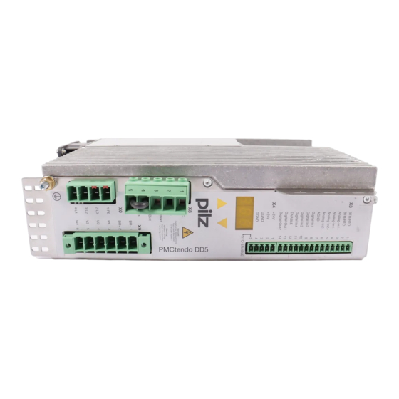
Sign In
Upload
Manuals
Brands
Pilz Manuals
Amplifier
PMCtendo DD5
Pilz PMCtendo DD5 Manuals
Manuals and User Guides for Pilz PMCtendo DD5. We have
4
Pilz PMCtendo DD5 manuals available for free PDF download: Operating Manual, Installation Manual
Pilz PMCtendo DD5 Operating Manual (209 pages)
Servo amplifiers
Brand:
Pilz
| Category:
Amplifier
| Size: 6.96 MB
Table of Contents
Table of Contents
3
Chapter 1 Introduction
7
Validity of the Documentation
7
Retaining the Documentation
7
Overview of Documentation
8
Definition of Symbols
9
Chapter 2 Overview
13
Chapter 3 Safety
20
Intended Use
20
Use of Qualified Personnel
21
Warranty and Liability
22
Disposal
22
Safety During Operation
23
Standards
24
Stop and E-STOP Functions
26
Stop Functions
26
E-STOP Functions
27
Chapter 4 Function Description
29
Overview
29
Power Element
31
Mains Voltage
31
Motor Connection
34
Motor Holding Brake
34
Brake Resistor
37
Intermediate Circuit
38
Control Element
39
Supply Voltage 24 VDC
39
Overview
40
Digital Inputs
40
Digital Outputs
42
Safety Function STO
43
Safety Information
43
Signal States
44
Connection Example
45
Analogue Inputs
45
Encoder Systems
47
Overview
47
Resolver
50
Sincos Encoder
50
Incremental Encoder
53
Absolute Encoder with SSI Interface
55
Electronic Gearing
55
Master-Slave Mode
57
Encoder Emulation
58
Communication Interfaces
61
RS232 Interface
61
Canopen Interface
61
Tools
62
Expansion Cards
63
Expansion Card for SERCOS Interface
66
Expansion Card for Devicenet
68
Fieldbus Junction Box
70
Switch On/Switch off Behaviour
72
Normal Operation
74
Fault Condition
75
Implementation of Stop Categories
77
Stop Category 0
77
Stop Category 2
81
Chapter 5 Installation
85
General Requirements
85
Dimensions
86
Installing the Servo Amplifier
87
Installing the Expansion Cards
89
Installing the Fieldbus Junction Box
90
Chapter 6 Wiring
91
Connector Description
91
Block Diagram
92
Wiring Guidelines
94
Protection against Contact
95
Leakage Current
95
Residual Current Devices FI
96
Isolating Transformer
97
Connection Cables
98
Wiring Procedure
99
EMC-Compliant Wiring
101
Shielding
101
Shield Connection on the Front Plate
102
Motor Connection
103
Filters
104
Chokes
104
Power Element
111
Mains Voltage
111
Under "Connection Cables", Please Note the Requirements for The: Cable Cross Sections Insulation Material
112
Digital Inputs
113
Digital Outputs
115
Analogue Inputs
116
Encoder Systems
117
Resolver
117
Sincos Encoder with HIPERFACE Inter
119
Sincos Encoder with Endat 2.1 Interface
120
Sincos Encoder with Endat 2.2 Interface
122
Sincos Encoder with BISS Interface, Ana
125
Sincos Encoder with BISS Interface, Digital
126
Sincos Encoder with SSI Interface
128
Sincos Encoder Without Data Track
130
Incremental Encoder ROD (Aquadb) 5 V
133
Incremental Encoder ROD (Aquadb) 5 V, 1.5 Mhz
134
Absolute Encoder with SSI Interface
138
Electronic Gearing, Master-Slave Mode
140
Encoder Emulation
144
Communication Interfaces
146
RS232 Interface
146
Canopen Interface
148
Expansion Cards
150
Expansion Card I/O-14/08
150
Expansion Card for SERCOS Interface
153
Expansion Card for Devicenet
154
Fieldbus Junction Box
155
Chapter 7 Commissioning
157
Safety Information
157
Commissioning the Servo Amplifier
159
Gather the Project Data
159
Wire Components
159
Preparing for Commissioning
161
Connect 24 VDC Supply Voltage
161
Establish Communication Pmctendo DD5
162
Set Parameters for the Servo Amplifier
162
Perform the First Test Run
164
Leds and Keys
166
Key Functions
166
Standard Menu
167
Advanced Menu
168
Messages/Errors
170
Warning Messages
170
Chapter 8 Technical Details
173
Pmctendo DD5.03/230V
173
Pmctendo DD5.06/230V
176
Pmctendo DD5.10/230V
179
Pmctendo DD5.01/480V
182
Pmctendo DD5.03/480V
185
Pmctendo DD5.06/480V
188
Chapter 9 Appendix
194
Glossary
201
Abbreviations
202
Index
204
Advertisement
Pilz PMCtendo DD5 Operating Manual (197 pages)
Servo amplifier
Brand:
Pilz
| Category:
Amplifier
| Size: 5.25 MB
Table of Contents
Table of Contents
4
Signal States
38
Connection Example
39
Analogue Inputs
40
Encoder Systems
41
Overview
41
Encoder
44
Incremental Encoder
44
Absolute Encoder with SSI Interface
44
Hall Encoder
44
Electronic Gearing
52
Stepper Motor Control Systems (Pulse/Direction)
53
Master-Slave Mode
53
Encoder Emulation
54
Communication Interfaces
57
RS232 Interface
57
Canopen Interface
57
Tools
57
Expansion Cards
58
Expansion Card I/O-14/08
58
PROFIBUS DP Interface Expansion Card
60
Fieldbus Junction Box
61
PROFINET Expansion Card
62
Expansion Card Fan Controller
62
Ethercat Expansion Card
63
Switch On/Switch off Behaviour
63
Normal Operation
65
Fault Condition
66
Implementation of Stop Categories
68
Stop Category 0
68
Stop Category 2
70
Installation
73
General Requirements
73
Dimensions
74
Installing the Servo Amplifier
74
Installing the Expansion Cards
76
Installing the Fieldbus Junction Box
77
Wiring
78
Connector Description
78
Block Diagram
79
Wiring Guidelines
81
Leakage Current
82
Protection against Contact
82
Residual Current Devices FI
83
Isolating Transformer
84
Connection Cables
84
Wiring Procedure
85
EMC-Compliant Wiring
85
Earthing
86
Shielding
86
Shield Connection on the Front Plate
87
Motor Connection
87
Filters
88
Chokes
89
Power Element
89
Mains Voltage
89
Motor with Brake
91
External Brake Resistor
92
Intermediate Circuit
95
Energy Store Pmcenergy SD
96
Control Element
99
Supply Voltage 24 VDC
99
Digital Inputs
100
Digital Outputs
101
Analogue Inputs
102
Encoder Systems
103
HIPERFACE DSL, One-Cable Connection
103
SFD3, One-Cable Connection
105
Resolver
105
Sincos Encoder with HIPERFACE Interface
107
Sincos Encoder with Endat 2.1 Interface
109
Encoder with Endat 2.2 Interface
111
Sincos Encoder with BISS Interface, Analogue
113
Encoder with BISS Interface, Digital
115
Sincos Encoder with SSI Interface
117
Sincos Encoder Without Data Track
119
Sincos Encoder with Hall Encoder
121
Incremental Encoder ROD (Aquadb) 5 V, 350 Khz
123
Incremental Encoder ROD (Aquadb) 5 V, 1.5 Mhz
125
Incremental Encoder ROD (Aquadb) 5 V, with Zero Pulse, with Hall Encoder
129
Incremental Encoder ROD (Aquadb) 5 V, with Zero Pulse, with Hall Encoder (X1/X5)
131
Incremental Encoder ROD (Aquadb) 24 V, Without Zero Pulse
133
Incremental Encoder ROD (Aquadb) 24 V, Without Zero Pulse, with Hall Encoder
134
Absolute Encoder with SSI Interface
137
Hall Encoder
139
Electronic Gearing, Master-Slave Mode
140
Encoder Emulation
144
Key Functions
159
Status Indicator
160
Standard Menu
161
Advanced Menu
162
Messages/Errors
162
Status Messages
162
Error Messages
163
Warning Messages
164
Expansion Cards
165
PROFINET Interface Expansion Card
165
PROFIBUS DP Interface Expansion Card
165
Technical Details Pmctendo DD5.01/480V
166
Technical Details Pmctendo DD5.03/230V
170
Technical Details Pmctendo DD5.03/480V
174
Technical Details Pmctendo DD5.06/230V
178
Technical Details Pmctendo DD5.06/480V
182
Technical Details Pmctendo DD5.10/230V
186
Safety Characteristic Data
190
Order Reference
191
Order Reference for Device
191
Interface Cable, Interface Adapter
191
Expansion Cards
191
Spare Connector Set
191
Energy Store
192
Pilz PMCtendo DD5 Installation Manual (120 pages)
Motion Control
Brand:
Pilz
| Category:
Industrial Equipment
| Size: 5.54 MB
Table of Contents
1 General Conditions
2
Copyright
2
Notes
2
Previous Editions
2
2 Table of Contents
3
3 Type Key
6
Type Pmctendo DD5
6
Type Pmcprimo Drive3
6
4 Safety Instructions
7
5 European Directives and Standards
8
6 Abbreviations and Symbols
10
7 General
11
About this Manual
11
Requirements
11
Use as Directed
11
Instrument Description
13
Package Supplied
13
Common Accessories
13
Accessories for Pmcprimo Drive3
13
The Pmctendo DD5 Family of Digital Servo Amplifiers
14
The Pmcprimo Drive3 Family of Digital Servo Amplifiers
16
Connection to Various Electrical Supply Networks
17
Components of a Servo System
18
Technical Data
19
Technical Data 230 V Series
19
Technical Data 480 V Series
20
Inputs / Outputs
21
Recommended Tightening Torques
21
Fusing
21
Permissible Ambient Temperatures, Ventilation, Mounting Position
22
Conductor Cross-Sections
22
LED Display
23
Control Circuit for Motor-Holding Brake
24
Grounding System
25
Regen Circuit
25
Functional Description
25
Technical Data
26
Switch-On and Switch-Off Behavior
27
Stop Function as Per en 60204 (VDE 0113)
27
Emergency Stop Strategies
28
8 Installation
29
Guide to Installation and Wiring
30
Assembly
31
Dimensions
32
Wiring
33
Connection Diagram General
34
Connection Diagram Pmcprimo Drive3
35
Connector Assignments General
36
Connector Assignments Pmcprimo Drive3
37
Notes on Connection Technology
38
9 Interfaces
40
Block Diagram General
40
Block Diagram Pmcprimo Drive3
41
Electrical Supply
42
Mains Electrical Supply Connection (X0)
42
Auxiliary Supply (X4)
43
Supply (X10)
44
Master Encoder Supply (X10)
45
DC Bus Link (X8)
46
Motor Connection with Brake (X9)
47
External Regen Restistor (X8)
48
Feedback
49
Resolver X2
49
Comcoder (X1)
50
Incremental or Sine Encoder with Hall Sensors (X1)
51
Sine Encoder with Endat or HIPERFACE (X1)
52
Acuro Encoder, BISS Interface (X1)
53
Incremental Encoder (X5)
54
Sine Encoder Without Data Channel (X1)
55
Digital and Analog Inputs and Outputs
56
Analog Inputs (X3)
56
Digital Inputs (X3/X4)
58
Digital Inputs I1:1 - I1:8 (X10)
60
Digital Outputs (X3)
61
Digital Outputs (X10)
63
Encoder Emulation
64
Incremental Encoder Output - a Quad B (X5)
64
SSI Output (X5)
65
Master-Slave Operation, Encoder Master Control
66
Connection to a Pmctendo DD5 Master, 5V Signal Level (X5)
66
Connection to Incremental Encoder Master with 24V Signal Level (X3)
67
Connection to a Sine Encoder Master (X1)
68
Interface for Stepper Motor Controllers (Step and Direction)
69
Speed Profile and Signal Diagram
69
Connection to a Stepper Controller with 5V Signal Level (X5)
70
Connection to a Stepper Controller with 24V Signal Level (X3)
71
RS232 Interface, PC Connection (X6)
72
Interface Cable between the PC and Servo Amplifier
72
Canopen Interface (X6)
73
CAN-Bus Cable
73
CAN Bus Interface (X11/1,X11/2)
75
General
75
Connecting Pmcprimo Drive3 Systems
75
Speciality 1St Node
76
Speciality Last Node
76
Fault Detection
76
Connecting External Canopen Bus Devices
76
CAN Bus Interface (X11/4)
77
Master Encoder Interface (X11/4)
78
Incremental Encoder (ROD)
78
Absolute Encoder (SSI)
79
Panel Interface - Modbus (X11/3)
80
General
80
Interface
80
Profibus DP Slave Interface (X11/3)
81
General
81
Using the Profibus Interface with Pmcprimo
81
Example Using Profibus DP
82
Ethernet Interface (X11/5)
83
General
83
Interface
83
Configuration IP Address
83
Compact Flash Interface (X11/5)
84
General
84
Interface
84
Personnel Safe Restart Lock -AS
85
Technical Data and Pinning
85
Environment
85
Wiring
85
Functional Description
86
10 Setup
90
Important Notes
90
Guide to Setup
91
Setup Software Pdrive
92
Use as Directed
92
Software Description
92
Hardware Requirements
92
Minimum Requirements for the PC
92
Installation under WINDOWS 2000 / XP
92
Working with Pdrive
93
Parametrization of the Pmctendo DD5 and Pmcprimo Drive3
93
Multi-Axis Systems
93
Keypad Operation Pmctendo DD5
94
Keypad Operation Pmcprimo Drive3
96
Basic Key Operation
96
LED Display
96
Programming of the Pmcprimo Drive3
97
Error Messages Pmctendo DD5
98
Warning Messages Pmctendo DD5
99
Error Messages Pmcprimo Drive3
100
Status Messages Pmcprimo Drive3
101
11 Expansions and Accessories
102
Expansion Cards
102
Guide to Installation of Expansion Cards
102
Expansion Card -I/O-14/08
103
Expansion Card -PROFIBUS
106
Expansion Module -CAN Adapter
107
Pmcprimo Board and Pmcprimo Expansion Card
109
12 Appendix
112
Transport, Storage, Maintenance, Disposal
112
Finding and Removing Faults
113
Glossary
116
Index
118
Advertisement
Pilz PMCtendo DD5 Operating Manual (30 pages)
Servo amplifiers
Brand:
Pilz
| Category:
Servo Drives
| Size: 1.08 MB
Table of Contents
Table of Contents
3
General Information
4
About this Manual
4
Target Group
4
Definition of Symbols
5
Abbreviations Used
6
Safety
8
Intended Use
8
Notes on the Online Edition (PDF Format)
9
Installation/Commissioning
10
Assembly/Installation
10
Connection Technology
11
Commissioning
11
Guide to Commissioning
11
Ethercat Commissioning
12
Ethercat
13
Slave Register
13
AL Event (Interrupt Event) and Interrupt Enable
14
Interrupt Enable Register (Address 0X0204:0205)
14
AL Event (Address 0X220:0221)
14
Phase Runup
15
AL Control (Address 0X0120:0X0121)
15
AL Status (Address 0X0130:0X0131)
16
AL Status Code (Address 0X0134:0X0135)
16
Ethercat Communication Phases
17
Canopen over Ethercat (Coe) State Machine
18
Description of States
19
Commands in the Control Word
20
Bits of the Status Machine (Status Word)
21
Implemented Operating Modes
22
Setting the Ethercat Cycle Time
22
Recommended Cycle Time Based on the Operating Modes
23
Synchronisation Based on the Cycle Time
23
Latch- Control Word and Latch Status Word
24
Mailbox Handling
25
Mailbox Output
26
Mail Input
27
Example of a Mailbox Access
28
Advertisement
Related Products
Pilz PMCprotego D.48
Pilz PMCprotego D.72
Pilz PMCtendo DD5.01/480V
Pilz PMCtendo DD5.03/230V
Pilz PMCtendo DD5.03/480V
Pilz PMCtendo DD5.06/230V
Pilz PMCtendo DD5.06/480V
Pilz PMCtendo DD5.10/230V
Pilz PLID d1
Pilz PLID d1 C
Pilz Categories
Relays
Switch
Control Unit
I/O Systems
Security Sensors
More Pilz Manuals
Login
Sign In
OR
Sign in with Facebook
Sign in with Google
Upload manual
Upload from disk
Upload from URL