Pilz PMCtendo DD5 Operating Manual
Servo amplifier
Hide thumbs
Also See for PMCtendo DD5:
- Installation manual (120 pages) ,
- Operating manual (30 pages) ,
- Operating manual (209 pages)
Table of Contents
Advertisement
Quick Links
Advertisement
Table of Contents

Subscribe to Our Youtube Channel
Related Manuals for Pilz PMCtendo DD5


Summary of Contents for Pilz PMCtendo DD5
- Page 1 PMCtendo DD5 Servo amplifiers Operating Manual-1002236-EN-04...
- Page 2 Preface This document is the original document. All rights to this documentation are reserved by Pilz GmbH & Co. KG. Copies may be made for the user's internal purposes. Suggestions and comments for improving this documenta- tion will be gratefully received.
- Page 3 Mains voltage 4.2.2 Motor connection 4.2.3 Motor holding brake 4.2.4 Brake resistor 4.2.5 Intermediate circuit Control element 4.3.1 Supply voltage 24 VDC 4.3.2 Digital inputs and outputs 4.3.2.1 Overview 4.3.2.2 Digital inputs 4.3.2.3 Digital outputs Operating Manual PMCtendo DD5 1002236-EN-04...
-
Page 4: Table Of Contents
Stop Category 2 Section 5 Installation General requirements Dimensions Installing the servo amplifier Installing the expansion cards Installing the fieldbus junction box Section 6 Wiring Connector description Block diagram Wiring guidelines 6.3.1 Protection against contact Operating Manual PMCtendo DD5 1002236-EN-04... - Page 5 6.7.5.16 Incremental encoder ROD (AquadB) 24 V, without zero pulse 6.7.5.17 Incremental encoder ROD (AquadB) 24 V, without zero pulse, with Hall en- coder 6.7.5.18 Absolute encoder with SSI interface 6.7.5.19 Hall encoder 6.7.5.20 Electronic gearing, Master-Slave mode 6.7.5.21 Encoder emulation Operating Manual PMCtendo DD5 1002236-EN-04...
- Page 6 Warning messages Expansion cards 7.5.1 PROFINET interface expansion card 7.5.2 PROFIBUS DP interface expansion card Section 8 Technical details PMCtendo DD5.01/480V Section 9 Technical details PMCtendo DD5.03/230V Section 10 Technical details PMCtendo DD5.03/480V Section 11 Technical details PMCtendo DD5.06/230V Section 12 Technical details PMCtendo DD5.06/480V...
- Page 7 Contents 15.2.6 Connection cable to the motor series "PMCtendo SZ" Section 16 Appendix 16.1 Abbreviations Section Glossary Operating Manual PMCtendo DD5 1002236-EN-04...
- Page 8 You will need to be conversant with the information in these documents in order to fully un- derstand this manual. This operating manual is valid for the following products: PMCtendo DD5 from Version 1.4 1.1.1 Retaining the documentation This documentation is intended for instruction and should be retained for future reference.
- Page 9 It also highlights areas within the text that are of particular import- ance. INFORMATION This gives advice on applications and provides information on special fea- tures. Operating Manual PMCtendo DD5 1002236-EN-04...
- Page 10 Energy store PMCenergy SD [ 96]). Internal brake resistor is standard, external brake resistor available on request. Inverted rectifier with isolated current measurement and IGBT transistors Connection of synchronous servo motors, linear motors, asynchronous motors Operating Manual PMCtendo DD5 1002236-EN-04...
- Page 11 CoDeSys (development environment in accordance with IEC 61131-3) Via the PROFINET-/ETHERNET parameter channel (PASmotion) (Requirement: The expansion card PROFINET is inserted) Operation and display Servo amplifier operated via two keys Three-digit LED display for status and messages Operating Manual PMCtendo DD5 1002236-EN-04...
- Page 12 EN 61800-5-1 – Soft start, overvoltage detection, short circuit protection, phase failure monitoring – Temperature monitoring of servo amplifier and motor (when using Pilz motors with ready-made cables) Protection of personnel and plant – Safety function STO – Safe Torque Off Single-channel without feedback: Up to PL d (Cat.
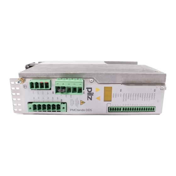
- Page 13 7: Connection for motor brake Digital-In4 ENABLE Digital-Out1 8: Supply voltage 24 VDC and safety func- Digital-Out2 tion STO +24 V +24 V DGND 9: Inputs and outputs, ENABLE, operational DGND readiness STO-ENABLE n.c. Plan view of the PMCtendo DD5 Operating Manual PMCtendo DD5 1002236-EN-04...
- Page 14 14: RS232 interface for commissioning and parameter setting or CANopen controller Plan view of the PMCtendo DD5 Scope of supply This is what you receive when you order a servo amplifier from the PMCtendo series:...
- Page 15 Overview Type code Type Supply voltage PMCtendo DD5._ _ / _ _ _ / 0 / 0 / 0 / _ _ _ _ _ VAC Series 110...230 VAC 230V Current Size 230V Series Series 480V 208...480 VAC 10 A...
- Page 16 Type Type key Ident. No. Order number Prod. version Product version Firmware Firmware version Mains Voltage Mains voltage Power Power Inom Continuous output current Year of manufacture Prot. type Protection type Ambient temp Ambient temperature Operating Manual PMCtendo DD5 1002236-EN-04...
- Page 17 Servo amplifiers with higher commutation frequencies are available only on request. INFORMATION On servo amplifiers from firmware version 5.71, no firmware version prior to Version 5.71 can be loaded. It is possible to downgrade from Version 5.73 to 5.71, for example. Operating Manual PMCtendo DD5 1002236-EN-04...
- Page 18 Tightening torque for field wiring terminals X0, X8, X9: 0.5 - 0.6Nm (4.43 to 5.31 lbf in) Use in a pollution degree 2 environment. These devices provide solid state motor overload protection at 130% of full load cur- rent. Operating Manual PMCtendo DD5 1002236-EN-04...
- Page 19 The safety function STO switches the motor to torque-free. On motors without a safe holding brake, moving parts present a threat to life. Use an additional mechanical measure to block the drives safely (e.g. with the motor holding brake), particularly with suspended loads. Operating Manual PMCtendo DD5 1002236-EN-04...
- Page 20 In safety-related applications, please comply with the mission time T in the safety-re- lated characteristic data. When decommissioning, please comply with local regulations regarding the disposal of electronic devices (e.g. Electrical and Electronic Equipment Act). Operating Manual PMCtendo DD5 1002236-EN-04...
- Page 21 When the supply voltage is switched on, do not: - Open the housing - Connect or disconnect connection terminals - Connect or disconnect a connection wiring - Install or remove accessories Operating Manual PMCtendo DD5 1002236-EN-04...
- Page 22 The servo amplifier may not be used for its intended purpose until it has been established that the plant or machinery complies with the provi- sions of the following directives: EU Machinery Directive (2006/42/EC) EU EMC Directive (2014/30/EU) EU Low Voltage Directive (2014/35/EU) Operating Manual PMCtendo DD5 1002236-EN-04...
- Page 23 IEC 62061 (Safety of machinery - Functional safety of safety-related electrical, elec- tronic and programmable electronic control systems) The machine or plant manufacturer must check to see whether any additional standards or EU directives are applicable for his plant or machinery. Operating Manual PMCtendo DD5 1002236-EN-04...
- Page 24 The E-STOP shall override all other functions and operations in all modes. Power to the machine actuators, which can cause hazardous conditions, shall be – removed as quickly as possible without creating other hazards (e.g. category 0 stop with safety function STO). Operating Manual PMCtendo DD5 1002236-EN-04...
- Page 25 This leads to a Category 0 stop. The emergency stop must be implemented us- ing other measures (e.g. protection against direct contact) if a Category 0 stop is not per- mitted for the machine. Operating Manual PMCtendo DD5 1002236-EN-04...
- Page 26 Function description Function description Overview The PMCtendo DD5 is a digital servo amplifier which drives servo motors with speed, torque and/or position control. It is suitable for closed loop operation of brushless, syn- chronous servo motors and asynchronous motors. The servo amplifier consists of...
- Page 27 Digital Charging circuit inputs Intermediate circuit capacitor Digital outputs Control system Brake Control chopper Operational Monitoring readiness Communication Inverted rectifier Analogue inputs Safety function Supply voltage Incremental encoder Holding brake Fig.: Block diagram PMCtendo DD5 Operating Manual PMCtendo DD5 1002236-EN-04...
- Page 28 Use isolating transformers for asymmetrically earthed or unearthed 400 V … 480 V supplies. The servo amplifier is suitable for connection to TT and TN networks. Depending on the device type, the voltage range of the servo amplifier is 3 x 110 VAC – 3 x 230 VAC or 3 x 208 VAC - 3 x 480 VAC. Operating Manual PMCtendo DD5 1002236-EN-04...
- Page 29 This will prevent overvoltages between the external conductors and the servo amplifier housing. The isolating transformers must have the relevant input and output voltages. Operating Manual PMCtendo DD5 1002236-EN-04...
- Page 30 110 ... 230 V 400 ... 480 V 110 ... 230 V 400 ... 480 V (10) 110 ... 230 V 400 ... 480 V 110 ... 230 V (11) Fig.: Connection types for the mains connection Operating Manual PMCtendo DD5 1002236-EN-04...
- Page 31 Thermal switches and motor feedback systems on the servo motor are evaluated. In the commissioning software (PASmotion) it is possible to select from a database the appropriate data record and parameters to suit the Pilz motor. Motor cables are available ready-assembled from Pilz as an accessory.
- Page 32 Emergency braking ramp n-set value DECDIS internal Rampe+ Motor speed VEL0 max. 5 s EMRGTO Internal enable TBRAKE def. 100 ms Brake BR+ Braking power t brH t brL STO-ENABLE Fig.: Timing diagram for motor holding brake Operating Manual PMCtendo DD5 1002236-EN-04...
- Page 33 Single amplifier – If the power regenerated from the motor is greater than the set brake power (as an average over time or as a peak value), a message will appear (see section entitled “Messages/Errors”). Operating Manual PMCtendo DD5 1002236-EN-04...
- Page 34 Exchanges data between the servo amplifier and periphery Records and displays errors and messages Performs protective functions for the servo amplifier and motor Processing of the setpoints with current, speed and position controllers is fully digital. Operating Manual PMCtendo DD5 1002236-EN-04...
- Page 35 The power supplies must comply with EN 60950-1, 05/2006, EN 61558-2-6, 11/1997. 4.3.2 Digital inputs and outputs 4.3.2.1 Overview The PMCtendo DD5 has digital inputs and outputs for a range of applications. The digital signals can be logically linked within the PDrive commissioning software. Connect- ors/ter- Designa- Num-...
- Page 36 EEPROM and the device must be reset (e.g. using the commis- sioning software PASmotion). Safety function STO, digital input STO-ENABLE (X4/5) The digital input STO-ENABLE is used to shut down the inverted rectifier safely. The safety function STO is triggered through a single channel. Operating Manual PMCtendo DD5 1002236-EN-04...
- Page 37 The safety function STO on the servo amplifier can be triggered by an external safe control system (semiconductor output or positive-guided relay contact). 4.3.3.1 Safety information Please note the following safety guidelines: Please note the intended use of the safety function STO (see Chapter entitled “Safety”). Operating Manual PMCtendo DD5 1002236-EN-04...
-
Page 38: Signal States
2. Disable the servo amplifier if speed = 0 min (ENABLE = 0 V) 3. If a suspended load is present, use an additional mechanical measure to block the drive 4. Activate safety function (STO-ENABLE = 0 V) Operating Manual PMCtendo DD5 1002236-EN-04... -
Page 39: Connection Example
The safety function STO complies with PL d (Cat. 2) of EN ISO 13849-1 and SIL CL 2 of EN/IEC 62061. The relays' wiring must comply with the category or performance level required for the ap- plication. Further information on the safety relays is available from Pilz. 24 V STO-ENABLE... -
Page 40: Analogue Inputs
Positive voltage at terminal X3/5 (+) to terminal X3/6 (-) Reversing the direction of rotation: Anti-clockwise rotation of motor shaft (facing the shaft): – Swap the configuration of terminals X3/3-4 or X3/5-6 or change the Count direc- tion parameter in the "Feedback" window (0/1). Operating Manual PMCtendo DD5 1002236-EN-04... -
Page 41: Encoder Systems
Gearing One en- In the mo- FBTYPE coder Two en- In the mo- FBTYPE coders (ex- ternal posi- External EXTPOS tion) Two en- In the mo- FBTYPE coders (external External GEAR- MODE control) Operating Manual PMCtendo DD5 1002236-EN-04... - Page 42 (caused by the wrong supply voltage). The table below provides an overview of the supported encoder types and their corres- ponding parameters and connectors. Feedback types with one-cable connection (power and feedback in one cable) Hybrid cable Hiperface DSL Operating Manual PMCtendo DD5 1002236-EN-04...
- Page 43 Incremental encoder ROD (AquadB) 5 V, with zero pulse + Hall encoder Incremental encoder ROD (AquadB) 5 V, with zero X5 / X1 pulse + Hall encoder Incremental encoder ROD (AquadB) 24 V, without 12, 16 24 V zero pulse Operating Manual PMCtendo DD5 1002236-EN-04...
-
Page 44: Encoder
X2: Motor encoder (resolver) X1: Motor encoder (e.g. Sin- incremental encoder) Cos encoder) X5: External encoder (e.g. X2: Motor encoder (resolver) X5: External encoder (e.g. incremental encoder) incremental encoder) EXTPOS FBTYPE FBTYPE FBTYPE EXTPOS EXTPOS Operating Manual PMCtendo DD5 1002236-EN-04... - Page 45 X2 Slave: Motor encoder (resolver) coder) X5 Master: External encoder (e.g. incre- X2 Master: Motor encoder (resolver) mental encoder) X5 Master, Slave: Master-Slave connection Slave Slave Master Master GEARMODE GEARMODE ENCMODE ENCMODE EXTPOS FBTYPE FBTYPE FBTYPE FBTYPE EXTPOS Operating Manual PMCtendo DD5 1002236-EN-04...
- Page 46 Cutoff frequency (sin, cos): 350 kHz Setting the parameters: Parameter Parameter Parameter Supply Encoder type FBTYPE EXTPOS GEARMODE voltage Up SinCos encoder 5 V with 5 V +/- 5% Hall SinCos encoder 12 V with 7.5 … 11 V Hall Operating Manual PMCtendo DD5 1002236-EN-04...
- Page 47 SinCos encoder with SSI interface (X1) Functions: SinCos encoder with SSI interface connected as a linear feedback system Setting the parameters: Parameter Parameter Parameter Encoder type FBTYPE EXTPOS GEARMODE SinCos encoder with SSI interface 5 V Operating Manual PMCtendo DD5 1002236-EN-04...
- Page 48 (motor phase parameter MPHASE). Depending on the encoder type, either a wake & shake is executed or the value for the MPHASE parameter is taken from the servo amplifier's EEPROM. Operating Manual PMCtendo DD5 1002236-EN-04...
- Page 49 MPHASE from EE- 350 kHz PROM Incremental encoder 5 V, MPHASE with wake 350 kHz & shake Incremental encoder 5 V, MPHASE from EE- 1.5 MHz PROM Incremental encoder 5 V, MPHASE with wake 1.5 MHz & shake Operating Manual PMCtendo DD5 1002236-EN-04...
- Page 50 Temperature monitoring on the motor is connected to X1 and is evaluated there Cutoff frequency at X3: 100 kHz Cutoff frequency at X1: 350 kHz Setting the parameters: Parameter Parameter Parameter Encoder type FBTYPE EXTPOS GEARMODE Incremental encoder 5 V, without zero pulse + Hall encoder Operating Manual PMCtendo DD5 1002236-EN-04...
- Page 51 Binary or gray code Cutoff frequency: 1.5 MHz Resolution per revolution: Max. 16 Bit Revolutions: Max. 16 Bit Motor temperature monitoring Setting the parameters: Parameter Parameter Parameter Encoder type FBTYPE EXTPOS GEARMODE Absolute encoder with SSI interface Operating Manual PMCtendo DD5 1002236-EN-04...
-
Page 52: Electronic Gearing
Encoder with BiSS digital interface 11, 12 Encoder with EnDat 2.1 interface Encoder with EnDat 2.2 interface SinCos encoder with HIPERFACE interface SinCos encoder without data track 6, 7 Incremental encoder (AquadB) 5 V, 350 kHz Operating Manual PMCtendo DD5 1002236-EN-04... -
Page 53: Stepper Motor Control Systems (Pulse/Direction)
Slave is activated by the Master via the encoder interface X5 Example of Master-Slave mode for 2 PMCtendo DD5: Parameter settings in the PDrive commissioning software: Master: "Encoder Emulation" window, position information X5 Slave: "Electronic gearing" window, GEARMODE Operating Manual PMCtendo DD5 1002236-EN-04... -
Page 54: Encoder Emulation
Position of the zero pulse within one mechanical revolution (NI-OFFSET parameter) Resolution (before multiplication) in counts/revolution ENCMODE = 1: Incremental encoder compatible signals from the resolver or SinCos encoder ENCMODE = 3: Encoder signal from X1 is available at X5 Operating Manual PMCtendo DD5 1002236-EN-04... - Page 55 6-pole resolvers to one third of a re- volution. Multiturn: The leading 12 to 16 Bits indicate the number of revolutions; the following 16 bits state the position. Operating Manual PMCtendo DD5 1002236-EN-04...
- Page 56 Min. period length T = 600 ns Timeout t = 1.3 μs or 10 μs (SSITOUT parameter) Output |ΔU| I ≥ 2 V/20 mA Input |ΔU| ≥ 0.3 V Default count direction: Upwards, facing the motor axis when rotating clockwise Operating Manual PMCtendo DD5 1002236-EN-04...
-
Page 57: Communication Interfaces
The oscilloscope function enables all the control parameters (current, speed and posi- tion controllers) to be optimised quickly and simply. The safety functions to be carried out by the safety card are defined in the Configurator PASconfig SDrive: – Configuration of the safety functions Operating Manual PMCtendo DD5 1002236-EN-04... -
Page 58: Expansion Cards
Setting of limit values, braking ramps for the safety functions, monitoring of motion sequences A database containing motor parameters for Pilz motors makes it easier to set paramet- ers for the servo amplifier. If the correct motor-related data has been loaded from the database, the control para- meters generally only need to be optimised. - Page 59 Starts the motion task that is addressed via the inputs A0 ... A7 (connector X11A/1...8). InPosition When a motion task reaches its target position (in the “In-Position” window), the output registers a high signal. An open circuit will not be detected. Operating Manual PMCtendo DD5 1002236-EN-04...
-
Page 60: Profibus Dp Interface Expansion Card
The servo amplifier supplies the voltage to the expansion card. Fig.: Front view of the PROFIBUS DP expansion card INFORMATION For information on the PROFIBUS DP expansion card, please refer to the operating manual "PROFIBUS DP for PMCtendo DD5 and PMCprotego D". Operating Manual PMCtendo DD5 1002236-EN-04... -
Page 61: Fieldbus Junction Box
CAN monitoring voltage is de-selected Example for networking two PMCtendo DD5: PC connected to the first PMCtendo DD5 connector X6A PMCtendo DD5 connector X6 linked with fieldbus adapter CAN1, connector X6B: CAN Master CAN2: Socket X6C: Connection between the two PMCtendo DD5 Terminating resistor on the last PMCtendo DD5 selected: CAN-Term switch = 1 (ON) INFORMATION Details of the connector pin assignment are available in Chapter 8, "Wiring"... -
Page 62: Profinet Expansion Card
PROFINET expansion card INFORMATION For information on the PROFINET expansion card, please refer to the oper- ating manual "PROFINET for PMCtendo DD5 and PMCprotego D". 4.4.5 Expansion card Fan Controller With the built-in fan controller, noise emissions are reduced. The expansion card must be specified when the servo amplifier is ordered. -
Page 63: Ethercat Expansion Card
This section describes the behaviour of the servo amplifier when switching on and off. It ex- plains the measures that are required to achieve compliance with the standards when a stop or E-STOP is performed during operation. Operating Manual PMCtendo DD5 1002236-EN-04... - Page 64 A potential malfunction of the holding brake must be consdiered. Bringing a motor to a standstill safely using the holding brake requires an additional electromechanical N/O con- tact for the holding device and a suppression device for the brake. Operating Manual PMCtendo DD5 1002236-EN-04...
-
Page 65: Normal Operation
Servo amplifiers on which the "Holding brake" function has been enabled have a separate procedure to switch off the inverted rectifier (see section in this chapter entitled "Motor hold- ing brake"). The drive is shut down safely using the safety function STO. Operating Manual PMCtendo DD5 1002236-EN-04... -
Page 66: Fault Condition
The diagram illustrates the start-up procedure and the sequence of the servo amplifier's in- ternal control system if the motor temperature is exceeded when the default parameters are set. The error F06 does not switch off the output stage immediately. Controlled braking is initiated when ACTFAULT = 1. Operating Manual PMCtendo DD5 1002236-EN-04... - Page 67 Even if there is no intervention from an external control system (in this example, the EN- ABLE signal remains active), the motor is immediately braked using the emergency braking ramp if an input phase fault is detected and the factory default setting is unchanged (ACT- FAULT = 1). Operating Manual PMCtendo DD5 1002236-EN-04...
-
Page 68: Implementation Of Stop Categories
If there is an internal fault on the servo amplifier, the motor is forcibly braked once K20 drops out. Make sure that the machine cannot be damaged by abrupt braking. Frequent forced braking using the holding brake built into the motor can damage the brake. Operating Manual PMCtendo DD5 1002236-EN-04... - Page 69 27 Ω (20 W) 1000 V 2.5 kW - 5 kW 8.2 Ω (50 W) 1000 V 5 kW - 10 kW 2.7 Ω (110 W) 1000 V 10 kW - 20 kW 1 Ω (300 W) 1000 V Operating Manual PMCtendo DD5 1002236-EN-04...
-
Page 70: Stop Category 2
If the mains is switched off, not only is a controlled braking procedure initiated but the mains voltage is galvanically isolated from the holding brake after a delay, which can be set on the timer. Operating Manual PMCtendo DD5 1002236-EN-04... - Page 71 27 Ω (20 W) 1000 V 2.5 kW - 5 kW 8.2 Ω (50 W) 1000 V 5 kW - 10 kW 2.7 Ω (110 W) 1000 V 10 kW - 20 kW 1 Ω (300 W) 1000 V Operating Manual PMCtendo DD5 1002236-EN-04...
- Page 72 Motor output P Motor circuit brake resistor R 20 kW - 40 kW 0.33 Ω (600 W) 1000 V = (M ) / 9550 where: : Motor output [kW] : Standstill torque [Nm] : Rated speed [1/min] Operating Manual PMCtendo DD5 1002236-EN-04...
-
Page 73: Installation
The servo amplifier and power supply should be installed close to each other on the conductive, earthed mounting plate inside the control cabinet. Control cabinet lighting Use low interference panel lighting for inside the control cabinet. Operating Manual PMCtendo DD5 1002236-EN-04... -
Page 74: Dimensions
Dimensions 70 (2.76") 171 (6.73") 5 (0.2") < 200 (7.88"): PMCtendo DD5 115 ... 230 V AC < 230 (9.06"): PMCtendo DD5 208 ... 480 V AC Fig.: Dimensions of PMCtendo DD5 stated in mm (") Key: A: Motor connector B: Fan, only on device types –... - Page 75 Cable duct >75 >75 >40 >40 Cable duct >2,5 > 200: PMCtendo DD5 115 ... 230 VAC > 230: PMCtendo DD5 208 ... 480 VAC Mounting plate Control cabinet door conductive (zinc plated) Hexagon socket cylinder head screw DIN 912 PMCtendo DD5 Fig.: Installing the servo amplifier in a control cabinet...
-
Page 76: Installing The Expansion Cards
Do not twist the expan- sion card as you insert it! The expansion card is in- serted correctly when the front rests on the servo amplifier's mounting lugs. Fix the screws in place. Operating Manual PMCtendo DD5 1002236-EN-04... -
Page 77: Installing The Fieldbus Junction Box
Insert the CAN Adapter into the slot. Turn the screws into the thread on the spacer bolts. Connect the female D- Sub socket into the X6 connector on the servo amplifier. Operating Manual PMCtendo DD5 1002236-EN-04... -
Page 78: Wiring
230 V AC DGND DGND X8 DC-Bus STO-ENABLE X8 DC-Bus n.c. n.c. n.c. 480 V AC 230 V AC X9 Motor / Brake X9 Motor / Brake X0 Power X0 Power Fig.: Connector pin assignment PMCtendo DD5 Operating Manual PMCtendo DD5 1002236-EN-04... -
Page 79: Block Diagram
X1, X2, X6, X9 Shield in the connector housing X3, X8 Shield on the front plate Protective earth, PE Mounting plate Wide area, electrical connection between the designated device and the mounting plate in the control cabinet Operating Manual PMCtendo DD5 1002236-EN-04... - Page 80 DGND I/O-GND R Be F B2 Master-Slave Pulse F N3 F N2 F N1 CAN Master F H1 F H2 RS 232 +24 V +24 V F H3 XGND XGND Fig.: Block diagram PMCtendo DD5 Operating Manual PMCtendo DD5 1002236-EN-04...
-
Page 81: Wiring Guidelines
(see section entitled "Connection cables"). To achieve the maximum cable length, use cable material of the quality described under "Connection cables". E-STOP circuit The relay output for operational readiness (BTB) must be incorporated into the plant's emergency stop circuit. BTB contact: No safe signal Operating Manual PMCtendo DD5 1002236-EN-04... -
Page 82: Protection Against Contact
50 Hz current. It's not possible to measure the leakage cur- rents using a conventional multimeter because these too are standardised at 50 Hz current. The ready-made cables from Pilz are low capacity. The leakage current can be calculated approximately as follows (at 400 V mains voltage): = n x 20 mA + L x 1 mA/m at 8 kHz clock frequency at the output stage... -
Page 83: Residual Current Devices Fi
< 5 m), we recommend that each servo amplifier is protected individu- ally using a 30 mA universal current sensitive residual current device. Selective FI residual current devices will stop the protective device being triggered inadvert- ently. Operating Manual PMCtendo DD5 1002236-EN-04... -
Page 84: Isolating Transformer
Twisted pair, shiel- AGND, max 30 m Digital inputs and 0.5 mm² outputs, BTB, DGND, max. 30 m Holding brake (mo- Min. 0.75 mm 600 V, shielded, tor): check voltage drop +24 V/DGND Max. 2.5 mm² Check voltage drop Operating Manual PMCtendo DD5 1002236-EN-04... -
Page 85: Wiring Procedure
Check the wiring against the wiring diagrams EMC-compliant wiring In terms of electromagnetic compatibility (EMC), the servo amplifier meets the requirements of the following standards and laws: The EMC Directive 2014/30/EU The Low Voltage Directive 2014/35/EU. Operating Manual PMCtendo DD5 1002236-EN-04... -
Page 86: Earthing
Correct shielding of the following cables avoids interference coupling with – Motor cables – Cables to the external brake resistor – Encoder cables – Cables with digital and analogue signals – Cables to communications interfaces Operating Manual PMCtendo DD5 1002236-EN-04... -
Page 87: Shield Connection On The Front Plate
The cable shield for the motor cable is connected to the servo amplifier housing via the shielding plate. Use the ready-made motor cable from Pilz (accessory). However, If you wish to wire your own motor connector, follow the instructions below:... -
Page 88: Filters
Please note the following if additional filter measures are required: Earth the filter to avoid hazardous voltages Leakage currents are high frequency disturbances, so earth the filter at low impedance over a wide area. Operating Manual PMCtendo DD5 1002236-EN-04... -
Page 89: Chokes
The mains voltage requirements (network configurations) The use of isolating transformers Connector X0 Designation Description Earth conductor 1 PE Mains voltage phase L3 2 L3 Mains voltage phase L2 3 L2 Mains voltage phase L1 4 L1 Connector pin assignment Operating Manual PMCtendo DD5 1002236-EN-04... - Page 90 1.5 A, 3 A 6 A, 10 A Blow-out fuse or similar 6 AT 10 AT Protection European types: gRL or gL 400 V/500 V, T = slow acting American types: Fuse classes RK5/CC/J/T, 600VAC 200kA, time-delay Operating Manual PMCtendo DD5 1002236-EN-04...
-
Page 91: Motor With Brake
The motor connection must be shielded appropriately. Connector X9 Designation Description Brake- Brake+ Earth conductor Motor connection phase U Motor connection phase V Motor connection phase W Connector pin assignment Operating Manual PMCtendo DD5 1002236-EN-04... -
Page 92: External Brake Resistor
The wires to the brake (BR +/BR-) should be shielded separately. Connect the shielding on both ends. Connection 6.6.3 External brake resistor Under “Connection cables”, please note the requirements for the: Cable cross sections Insulation material Operating Manual PMCtendo DD5 1002236-EN-04... - Page 93 Device type PMCtendo DD5 PMCtendo DD5 .03/230 .01/480 .06/230 .03/480 Rated voltage Voltage class of DC power supply fuse .10/230 .06/480 110/115 V min. 250 VDC 230 V min. 250 VDC 400 V min. 440 VDC Operating Manual PMCtendo DD5 1002236-EN-04...
- Page 94 480 V 600 – 1000 VDC Conductor cross 1.5 mm 1.5 mm section Fuse type Bussmann: up to 50 A: FWP-xxA14F, size 14 x 51 mm with 800 Vdc UL approval Fuse holder Bussmann: CH142D, CH22B Operating Manual PMCtendo DD5 1002236-EN-04...
-
Page 95: Intermediate Circuit
With multi-axis systems please note the specific conditions of your plant. On multi-axis sys- tems, servo amplifiers can be interconnected via the intermediate circuit. As with single-axis systems, max. cable runs can only be achieved if the material require- ments are strictly observed. Operating Manual PMCtendo DD5 1002236-EN-04... -
Page 96: Energy Store Pmcenergy Sd
This energy is usually imple- mented via brake resistors in power dissipation. If the energy is required, for example, with the next acceleration cycle, the energy stores supply the saved energy back in the intermediate circuit. Operating Manual PMCtendo DD5 1002236-EN-04... - Page 97 Expansion unit Fig.: PMCenergy SD, type key Legend Base unit Energy store Expansion unit Expansion module INFORMATION For notes on assembly, installation and commissioning please refer to the operating manual of the energy storage module. Operating Manual PMCtendo DD5 1002236-EN-04...
- Page 98 3 +RBext 4 +RBint 5 -RB Connector pin assignment Output circuit Energy store Energy store: Discharge bridge [E] between terminal 1: –DC PMCenergy SD.B PMCenergy SD.E RS422 terminal 2: Re- move BR. Servo Drive +Rbext/+DC +RBint Connection Operating Manual PMCtendo DD5 1002236-EN-04...
-
Page 99: Control Element
+24 V Pin 3 and 4 (DGND) +24 V +24 V DGND 24 V connection isolated DGND from external power supply, e.g. with isolating trans- former Noise suppression filters in- tegrated within the servo amplifier Connection Operating Manual PMCtendo DD5 1002236-EN-04... -
Page 100: Digital Inputs
DIGITAL-OUT1 14 Connector pin assignment Connector X4 Designation Description 3, 4 DGND Reference earth for digital inputs +24 V 1 STO-ENABLE STO – Safe torque off +24 V 2 DGND 3 DGND 4 STO-ENABLE 5 Operating Manual PMCtendo DD5 1002236-EN-04... -
Page 101: Digital Outputs
ANALOG-IN1+ BTB/RTO Relay contact for operational ANALOG-IN1- readiness, servo amplifier ANALOG-IN2+ ANALOG-IN2- AGND DIGITAL-OUT 1 Digital output 1 DIGITAL-IN1 DIGITAL-IN2 DIGITAL-OUT 2 Digital output 2 DIGITAL-IN3 DIGITAL-IN4 ENABLE DIGITAL-OUT1 13 DIGITAL-OUT1 14 Connector pin assignment Operating Manual PMCtendo DD5 1002236-EN-04... -
Page 102: Analogue Inputs
Analogue input 1- ANALOG-IN1+ ANALOG-IN1- ANALOG-IN2+ Analogue input 2+ ANALOG-IN2+ ANALOG-IN2- ANALOG-IN2- Analogue input 2- AGND DIGITAL-IN1 AGND Reference earth for analogue in- DIGITAL-IN2 puts DIGITAL-IN3 DIGITAL-IN4 ENABLE DIGITAL-OUT1 13 DIGITAL-OUT1 14 Connector pin assignment Operating Manual PMCtendo DD5 1002236-EN-04... -
Page 103: Encoder Systems
Under “Connection cables”, please note the requirements for the: Cable cross sections Insulation material NOTICE The connection cable must not exceed the maximum length of 25 m. The connection cable must not be interrupted or separated. Operating Manual PMCtendo DD5 1002236-EN-04... - Page 104 DSL+ DSL+ n. c. n. c. n. c. n. c. n. c. n. c. DSL- DSL- n. c.: Not connected Connector X9 Connection power Brake- Brake+ Earth conductor Motor connection phase U Motor connection phase V Motor connection phase W Operating Manual PMCtendo DD5 1002236-EN-04...
-
Page 105: Sfd3, One-Cable Connection
Information on the connection can be found in chapter HIPERFACE DSL, one-cable con- nection. 6.7.5.3 Resolver Under “Connection cables”, please note the requirements for the: Cable cross sections Insulation material If the cable length > 100 m, speak to our Customer Support. Operating Manual PMCtendo DD5 1002236-EN-04... - Page 106 Sine input Cosine input Reference output Connector pin assignment Input circuit Resolver Motor Thermal switch in the motor is connected via the re- solver cable at X2 Twisted pair, shielded Shield connection in the connector Connection Operating Manual PMCtendo DD5 1002236-EN-04...
-
Page 107: Sincos Encoder With Hiperface Interface
Parameter channel RS 485 n. c. ϑ Thermal switch (+) n. c. REFSIN Reference sine n. c. REFCOS Reference cosine n. c. Data- (RS 485) Parameter channel RS 485 ϑ Thermal switch (-) n. c. n. c.: Not connected Connector pin assignment Operating Manual PMCtendo DD5 1002236-EN-04... - Page 108 Wiring Input circuit SinCos encoder with HIPERFACE interface Motor Thermal switch in the motor is connected via the en- coder cable at X1. Twisted pair, shielded Shield connection in the connector Connection Operating Manual PMCtendo DD5 1002236-EN-04...
-
Page 109: Sincos Encoder With Endat 2.1 Interface
Channel B (cosine) Sense 0 V Supply voltage feedback 0 V Channel A (sine) Sense Us Supply voltage feedback +5 V DATA\ Data inverted ϑ Thermal switch (-) CLOCK\ Test pulse output inverted n. c.: Not connected Connector pin assignment Operating Manual PMCtendo DD5 1002236-EN-04... - Page 110 Wiring Input circuit SinCos encoder with EnDat interface Motor Thermal switch in the mo- tor is connected via the encoder cable at X1. Twisted pair, shielded Shield connection in the connector Connection Operating Manual PMCtendo DD5 1002236-EN-04...
-
Page 111: Encoder With Endat 2.2 Interface
Data inverted ϑ Thermal switch (-) CLOCK\ Test pulse output inverted n. c.: Not connected Connector pin assignment INFORMATION The encoder supply voltage from 3.6 – 14 V can be operated without a sensor cable. (FBTYPE 34) Operating Manual PMCtendo DD5 1002236-EN-04... - Page 112 X1. Twisted pair, shielded Shield connection in the connector 5V / 12V Connection INFORMATION The encoder supply voltage from 3.6 – 14 V can be operated without a sensor cable. (FBTYPE 34) Operating Manual PMCtendo DD5 1002236-EN-04...
-
Page 113: Sincos Encoder With Biss Interface, Analogue
Channel B (cosine) Sense 0 V Supply voltage feedback 0 V Channel A (sine) Sense Us Supply voltage feedback +5 V DATA\ Data inverted ϑ Thermal switch (-) CLOCK\ Test pulse output inverted n. c.: Not connected Connector pin assignment Operating Manual PMCtendo DD5 1002236-EN-04... - Page 114 BISS analog is connected via the en- coder cable at X1 Twisted pair, shielded Shield connection in the connector DATA DATA DATA\ DATA\ CLOCK CLOCK CLOCK\ CLOCK\ Sense Sense 5 V +/- 5 % Connection Operating Manual PMCtendo DD5 1002236-EN-04...
-
Page 115: Encoder With Biss Interface, Digital
Test pulse output n. c. Sense 0 V Supply voltage feedback 0 V n. c. Sense Us Supply voltage feedback +5 V DATA\ Data inverted ϑ Thermal switch (-) CLOCK\ Test pulse output inverted n. c.: Not connected Connector pin assignment Operating Manual PMCtendo DD5 1002236-EN-04... - Page 116 BISS digital is connected via the en- DATA DATA coder cable at X1 DATA\ DATA\ Twisted pair, shielded CLOCK CLOCK CLOCK\ CLOCK\ Shield connection in the connector Sense Sense 5 V +/- 5 % Connection Operating Manual PMCtendo DD5 1002236-EN-04...
-
Page 117: Sincos Encoder With Ssi Interface
Channel A (sine) Sense Us Supply voltage feedback +5 V ϑ Thermal switch n. c. not connected Connector pin assignment Connector X5 Designation Description Ground CLOCK\ Test pulse output inverted DATA Data DATA Data DATA\ Data inverted Operating Manual PMCtendo DD5 1002236-EN-04... - Page 118 Input circuit SinCos encoder with SSI interface Thermal switch in the motor is connected via the en- coder cable at X1 Twisted pair, shielded Shield connection in the connector Switch on supply voltage Up: ENCVON=1 Connection Operating Manual PMCtendo DD5 1002236-EN-04...
-
Page 119: Sincos Encoder Without Data Track
ϑ Thermal switch (+) n. c. Cosine + Sense 0 V Supply voltage 0 V Sine + Sense Us Supply voltage Zero pulse - ϑ Thermal switch (-) n. c. n. c.: Not connected Connector pin assignment Operating Manual PMCtendo DD5 1002236-EN-04... - Page 120 Wiring Input circuit SinCos encoder without data track Thermal switch in the motor is connected via the en- coder cable at X1. Twisted pair, shielded Shield connection in the connector Connection Operating Manual PMCtendo DD5 1002236-EN-04...
-
Page 121: Sincos Encoder With Hall Encoder
Hall-U Hall-U ϑ Thermal switch (+) Hall-V Hall-V Cosine + Sense 0 V Supply voltage 0 V Sine + Sense Us Supply voltage Zero pulse - ϑ Thermal switch (-) Hall-W Hall-W Connector pin assignment Operating Manual PMCtendo DD5 1002236-EN-04... - Page 122 Wiring Input circuit SinCos encoder with Hall Servo Drive Thermal switch in the motor is connected via the en- coder cable at X1. Twisted pair, shielded Shield connection in the connector Connection Operating Manual PMCtendo DD5 1002236-EN-04...
-
Page 123: Incremental Encoder Rod (Aquadb) 5 V, 350 Khz
Thermal switch (+) n. c. Channel B inverted Sense 0 V Supply voltage feedback 0 V Channel A inverted Sense Us Supply voltage feedback 5 V Reference pulse inverted ϑ Thermal switch (-) n. c. n. c.: Not connected Connector pin assignment Operating Manual PMCtendo DD5 1002236-EN-04... - Page 124 Wiring Input circuit Incremental encoder 5 V Thermal switch in the motor is connected via the en- coder cable at X1 Twisted pair, shielded Shield connection in the connector Connection Operating Manual PMCtendo DD5 1002236-EN-04...
-
Page 125: Incremental Encoder Rod (Aquadb) 5 V, 1.5 Mhz
Thermal switch (+) Channel A n. c. Sense 0 V Supply voltage feedback 0 V n. c. Sense Us Supply voltage feedback 5 V Channel B inverted ϑ Thermal switch (-) Channel A inverted n. c.: Not connected Connector pin assignment Operating Manual PMCtendo DD5 1002236-EN-04... - Page 126 If the cable length is > 50 m, please speak to our Customer Support. Connector X5 Designation Description n. c. Reference pulse Reference pulse inverted Channel A inverted Channel A Channel B Channel B inverted n. c. n. c. n. c. = not connected Connector pin assignment Operating Manual PMCtendo DD5 1002236-EN-04...
- Page 127 Supply voltage 5 V n. c. n. c. ϑ Thermal switch n. c. n. c. Sense 0 V Supply voltage feedback 0 V n. c. Sense Us Supply voltage feedback 5 V n. c. ϑ Thermal switch n. c. n. c. = not connected Connector pin assignment Operating Manual PMCtendo DD5 1002236-EN-04...
- Page 128 Wiring Input circuit Incremental encoder 5 V, 1.5 MHz Thermal switch in the motor is connected via the en- coder cable at X1 Twisted pair, shielded Shield connection in the connector Connection Operating Manual PMCtendo DD5 1002236-EN-04...
-
Page 129: Incremental Encoder Rod (Aquadb) 5 V, With Zero Pulse, With Hall Encoder
Hall-V Channel B inverted Sense 0 V Supply voltage feedback 0 V Channel A inverted Sense Us Supply voltage feedback 5 V Reference pulse inverted ϑ Thermal switch (-) Hall-W Hall-W n. c.: Not connected Connector pin assignment Operating Manual PMCtendo DD5 1002236-EN-04... - Page 130 Input circuit Incremental encoder 5 V with Hall encoder Servo Drive Thermal switch in the motor is connected via the en- Comcoder coder cable at X1 Twisted pair, shielded Shield connection in the connector Connection Operating Manual PMCtendo DD5 1002236-EN-04...
-
Page 131: Incremental Encoder Rod (Aquadb) 5 V, With Zero Pulse, With Hall Encoder (X1/X5)
Thermal switch (-) Hall-W Hall-W n. c.: Not connected Connector pin assignment Connector X5 Designation Description Ground Zero pulse + Zero pulse - Track A- Track A+ Track B+ Track B- n c n c Connector pin assignment Operating Manual PMCtendo DD5 1002236-EN-04... - Page 132 Input circuit Incremental encoder 5 V with Hall encoder Servo Drive Thermal switch in the motor is connected via the en- Comcoder coder cable at X1 Twisted pair, shielded Shield connection in the connector Connection Operating Manual PMCtendo DD5 1002236-EN-04...
-
Page 133: Incremental Encoder Rod (Aquadb) 24 V, Without Zero Pulse
DGND Reference earth for digital inputs Input circuit Incremental encoder 24 V, 100 kHz Thermal switch in the motor is connected to X1 or X2 DIGITAL-IN1 24 V DIGITAL-IN2 Shielded 24 V DGND X1/X2 Connection Operating Manual PMCtendo DD5 1002236-EN-04... -
Page 134: Incremental Encoder Rod (Aquadb) 24 V, Without Zero Pulse, With Hall Encoder
If the cable length is > 25 m, please speak to our Customer Support. Connector X3A/X3B Pin Designation Description DIGITAL-IN1 Track A DIGITAL-IN2 Track B Connector pin assignment Connector X4 Designation Description DGND Reference earth for digital inputs Connector pin assignment Operating Manual PMCtendo DD5 1002236-EN-04... - Page 135 Hall-U ϑ Thermal switch (+) Hall-V Hall-V n c Sense 0 V Supply voltage feedback 0 V n c Sense Us Supply voltage feedback 5 V n c ϑ Thermal switch (-) Hall-W Hall-W n. c.: Not connected Connector pin assignment Operating Manual PMCtendo DD5 1002236-EN-04...
- Page 136 Input circuit Incremental encoder 24 V with Hall encoder X3: 100 kHz X1: 350 kHz Servo Drive Thermal switch in the motor X3AB ROD (AquadB) + Hall is connected to X1 or X2 Shielded Connection Operating Manual PMCtendo DD5 1002236-EN-04...
-
Page 137: Absolute Encoder With Ssi Interface
Sense Us Supply voltage feedback +5 V ϑ Thermal switch Connector pin assignment Connector X5 Designation Description 0 V Supply voltage 0 V DATA Data CLOCK Test pulse output DATA\ Data inverted CLOCK\ Test pulse output inverted Operating Manual PMCtendo DD5 1002236-EN-04... - Page 138 Absolute encoder with SSI interface Thermal switch in the motor is connected via the en- Absolut SSI coder cable at X1 Twisted pair, shielded Shield connection in the connector Switch on supply voltage Up: ENCVON=1 Connection Operating Manual PMCtendo DD5 1002236-EN-04...
-
Page 139: Hall Encoder
Supply voltage 0 V n. c. Supply voltage n. c. Hall-U Hall-U ϑ Thermal switch (+) Hall-V Hall-V n. c. Supply voltage 0 V n. c. Supply voltage n. c. ϑ Thermal switch (-) Hall-W Hall-W n. c. not connected Connector pin assignment Operating Manual PMCtendo DD5 1002236-EN-04... -
Page 140: Electronic Gearing, Master-Slave Mode
Electronic gearing, Master-Slave mode Connection to a stepper motor control system with 5 V signal Connector X1 Designation Description Supply voltage 0 V DIR+ Direction PULS+ Pulse DIR- Direction inverted PULS- Pulse inverted Connector pin assignment Operating Manual PMCtendo DD5 1002236-EN-04... - Page 141 ENABLE DIGITAL-OUT1 13 DIGITAL-OUT1 14 Connector pin assignment Input circuit Pulse/direction 24 V - DIR: Direction Servo Drive Master - PULS: Pulse DIGITAL-IN1 - 24 VDC to earth DIGITAL-IN2 PULS - Shielded cable DGND Connection Operating Manual PMCtendo DD5 1002236-EN-04...
- Page 142 Connector pin assignment Output circuit Output of pulse/direction 5 Always connect GND to the Servo Drive Master earth on the control system Twisted pair, shielded Select R in accordance with the cable impedance, typically 120 Ω Connection Operating Manual PMCtendo DD5 1002236-EN-04...
- Page 143 Output of incremental en- coder signals Always connect GND to the Servo Drive Slave Servo Drive Master earth on the control system Twisted pair, shielded Select R in accordance with the cable impedance, typically 150 Ω Connection Operating Manual PMCtendo DD5 1002236-EN-04...
-
Page 144: Encoder Emulation
Output of incremental en- coder signals Shield connection in the connector Always connect GND to the earth on the control system Select R in accordance with the cable impedance, typically 150 Ω Max. cable length: 100 m Connection Operating Manual PMCtendo DD5 1002236-EN-04... - Page 145 Transient currents can be anticipated on longer cables. If this is the case you should use equipotential bonding cables. With the supply voltages switched off, connect the interface (X6) on the servo amplifier to a serial interface on the PC via a null modem cable. Operating Manual PMCtendo DD5 1002236-EN-04...
- Page 146 CANopen interface. The RS232 and CANopen interface use the same op- erating earth (GND). Cable: RS 232 RS 232 9-pin female D-Sub con- nector (servo amplifier) to 9-pin female D-Sub con- nector (PC) Operating Manual PMCtendo DD5 1002236-EN-04...
- Page 147 The terminating resistor is usually integrated within the connector and can be activated there. The cable runs for reliable communication decrease as the transmission rate is increased. The following values can be used as a guide, but they should not be regarded as limit val- ues: Operating Manual PMCtendo DD5 1002236-EN-04...
- Page 148 Shield CANopen bus cable INFORMATION As an expansion module, the fieldbus junction box CAN Adapter is available as an accessory to divide the CANopen interface of the PMCtendo DD5 into two parallel CANopen interfaces. Expansion cards 6.8.1 Expansion card I/O-14/08 Under “Connection cables”, please note the requirements for the:...
- Page 149 Digital output PosReg5 Digital output 24 VDC Supply voltage 24 VDC I/O-GND Reference earth Connector X4 Designation Description 3, 4 DGND Reference earth +24 V 1 +24 V 2 DGND 3 DGND 4 STO-ENABLE 5 Operating Manual PMCtendo DD5 1002236-EN-04...
- Page 150 (X11B/12) and DGND (X4) to I/O-GND on the control system Referenz S_fehl_clear FStartFolge FStartTippx Servo Drive X11B FRestart FStart_I/O InPos Folge-InPos / PosReg 0 S_fehl PosReg1 PosReg2 PosReg3 PosReg4 PosReg5 +24 V I/O-GND I/O-GND 3, 4 XGND Connection Operating Manual PMCtendo DD5 1002236-EN-04...
- Page 151 Wiring 6.8.2 PROFIBUS DP interface expansion card INFORMATION For information on the PROFIBUS DP expansion card, please refer to the operating manual "PROFIBUS DP for PMCtendo DD5 and PMCprotego D". 6.8.3 Fieldbus junction box X6A RS232 Designation Description Receive data Send data...
- Page 152 This chapter describes the procedure for commissioning the servo amplifier for the first time, by way of example. Please note that in this case the freely rotating motor is not yet connected to the prime mover. The servo amplifier is tested using a Pilz motor. INFORMATION The processes described here will help you understand the principle pro- cedure during commissioning.
-
Page 153: Operating Manual Pmctendo Dd5
1. Gather the project data 2. Wire components 3. Preparing for commissioning 4. Connect 24 VDC supply voltage 5. Establish communication PMCtendo DD5 <-> PC 6. Set parameters for the servo amplifier 7. Perform the first test run 1. Record project data... - Page 154 PMCtendo SZxx servo motor with standard encoder Mains contactor K1 (optional) 24 VDC power supply for control element Motor and encoder cable PC with installed commissioning software PASmotion. The current version is available on our website www.pilz.com. Operating Manual PMCtendo DD5 1002236-EN-04...
- Page 155 Connect A1 terminal to X3/1 via S3 switch – Connect A2 terminal to DGND on the supply voltage "STO-ENABLE deactivated" mode: Link terminals X4/5 and X4/1 Voltage for relay contact for operational readiness BTB/RTO: Link terminals X4/5 and X3/2 Operating Manual PMCtendo DD5 1002236-EN-04...
- Page 156 – LED display: YY. (current strength, flashing dot for CPU O.K.) – Relay contact BTB: closed 5. Establish communication PMCtendo DD5 <-> PC INFORMATION Details descriptions of the software tools used below are available on the Tools-CD. Start the commissioning software PASmotion.
- Page 157 The Motor Database window is opened. Select motor from motor database 1. Enter the motor's type code. You'll find the type code on the motor's type plate. Make your entries using buttons (1) or (2). Example: PMCtendo SZ.32/1/X/X/K/H/30 Operating Manual PMCtendo DD5 1002236-EN-04...
- Page 158 Overvoltage can destroy the device and lead to minor injuries. Select the correct mains voltage and the correct device type. 1. Select Analogue I/O in the Parameter Navigator. The Analogue I/O window is opened 2. If necessary, change the parameters: Operating Manual PMCtendo DD5 1002236-EN-04...
-
Page 159: Key Functions
Press twice in quick succession: De- crease the number by ten Hold down right-hand button and then press left-hand button: enter numbers, confirm entry The diagram below illustrates the function of the keys and LEDs. Fig.: Key functions Operating Manual PMCtendo DD5 1002236-EN-04... -
Page 160: Status Indicator
Commissioning 7.3.2 Status indicator Status Station address The amended address is saved automatically on exit. Fig.: Status indicator Operating Manual PMCtendo DD5 1002236-EN-04... -
Page 161: Standard Menu
Status 4: 24 V and mains voltage switched on Device signals current coding, power on and ENABLE. Point flashes Errors or warnings are displayed consecutively for 4 flash cycles each Parameter Fig.: Standard menu display Operating Manual PMCtendo DD5 1002236-EN-04... -
Page 162: Advanced Menu
Status message, no error . . . Status message Amplifier updating the start configuration Status message Status message, no error, programming mode - S - STO-ENABLE STO-ENABLE input = 0 V (if the drive is shut down) Operating Manual PMCtendo DD5 1002236-EN-04... -
Page 163: Error Messages
Handling error on the expansion card Reserved Reserved CAN Bus off Major CAN Bus communication error Warning Warning indicator assessed as an error Commutation error Commutation error Limit switch Reference run error (hardware limit switch reached) Operating Manual PMCtendo DD5 1002236-EN-04... -
Page 164: Warning Messages
Problem with the 24 V supply for the I/O expansion card SinCos feedback SinCos commutation (wake & shake) incomplete, will be cleared if amplifier is enabled and wake & shake is executed Table Error Fault as per speed/current table INXMODE 35 Operating Manual PMCtendo DD5 1002236-EN-04... -
Page 165: Expansion Cards
"PROFINET for PMCtendo DD5 and PMCprotego D". 7.5.2 PROFIBUS DP interface expansion card INFORMATION For information on the PROFIBUS DP expansion card, please refer to the operating manual "PROFIBUS DP for PMCtendo DD5 and PMCprotego D". Operating Manual PMCtendo DD5 1002236-EN-04... -
Page 166: Technical Details Pmctendo Dd5.01/480V
Technical details PMCtendo DD5.01/480V Technical details PMCtendo DD5.01/480V General Approvals Electrical data Supply voltage Voltage 3 x 208…3 x 480 V Kind Voltage tolerance -10 %/+10 % Frequency range AC 50 - 60 Hz Supply voltage Supply Voltage 24 V... - Page 167 Technical details PMCtendo DD5.01/480V Power element Rated intermediate circuit voltage 290 - 675 V Max. rated intermediate circuit voltage 900 V DC Power dissipation at max. mains voltage Without brake 40 W With inverted rectifier switched off 12 W Brake chopper power element...
- Page 168 Technical details PMCtendo DD5.01/480V Inputs Number Scan rate DIGITAL-IN-1 and 2 4 kHz Scan rate DIGITAL-IN 3 and 4 4 kHz Signal level at "0" -3 - +5 V DC Signal level at "1" 11 - 30 V DC Input current at signal level "0"...
- Page 169 Technical details PMCtendo DD5.01/480V Environmental data Cooling Free convection Noise emission 25 dB (A) Max. operating height above sea level 1000 m Max. operating height with power derating 1000 - 2500 m above sea level Power derating 1,5 %/100 m...
-
Page 170: Technical Details Pmctendo Dd5.03/230V
Technical details PMCtendo DD5.03/230V Technical details PMCtendo DD5.03/230V General Approvals Electrical data Supply voltage Voltage 1 x 110…3 x 230 V Kind Voltage tolerance -10 %/+10 % Frequency range AC 50 - 60 Hz Supply voltage Supply Voltage 24 V... - Page 171 Technical details PMCtendo DD5.03/230V Brake chopper power element Switch-on threshold at 230 V 400 V Max. overvoltage, intermediate circuit at 230 V 455 V Pulse brake power at 230 V 3,00 kW Internal brake resistor RBi 66 Ohm Continuous output RBi...
- Page 172 Technical details PMCtendo DD5.03/230V Semiconductor outputs (standard) Number Switching capability Current 0,01 A Galvanic isolation Relay outputs Operational readiness function Number Max. voltage AC 42 V Max. voltage DC 30 V Max. current 500 mA Communication interfaces RS232 and CANopen, on the same connector...
- Page 173 Technical details PMCtendo DD5.03/230V Environmental data Protection type In accordance with the standard EN 60529 Mounting area (e.g. control cabinet) IP54 Housing IP20 Terminals IP20 Mechanical data Mounting position vertical Material Housing Aluminium casting/stainless steel Dimensions Height 270,0 mm Height incl. connector...
-
Page 174: Technical Details Pmctendo Dd5.03/480V
Technical details PMCtendo DD5.03/480V Technical details PMCtendo DD5.03/480V General Approvals Electrical data Supply voltage Voltage 3 x 208…3 x 480 V Kind Voltage tolerance -10 %/+10 % Frequency range AC 50 - 60 Hz Supply voltage Supply Voltage 24 V... - Page 175 Technical details PMCtendo DD5.03/480V Power element Rated intermediate circuit voltage 290 - 675 V Max. rated intermediate circuit voltage 900 V DC Power dissipation at max. mains voltage Without brake 60 W With inverted rectifier switched off 12 W Brake chopper power element...
- Page 176 Technical details PMCtendo DD5.03/480V Inputs Number Scan rate DIGITAL-IN-1 and 2 4 kHz Scan rate DIGITAL-IN 3 and 4 4 kHz Signal level at "0" -3 - +5 V DC Signal level at "1" 11 - 30 V DC Input current at signal level "0"...
- Page 177 Technical details PMCtendo DD5.03/480V Environmental data Cooling Fans installed Noise emission 45 dB (A) Max. operating height above sea level 1000 m Max. operating height with power derating 1000 - 2500 m above sea level Power derating 1,5 %/100 m...
-
Page 178: Technical Details Pmctendo Dd5.06/230V
Technical details PMCtendo DD5.06/230V Technical details PMCtendo DD5.06/230V General Approvals Electrical data Supply voltage Voltage 1 x 110…3 x 230 V Kind Voltage tolerance -10 %/+10 % Frequency range AC 50 - 60 Hz Supply voltage Supply Voltage 24 V... - Page 179 Technical details PMCtendo DD5.06/230V Brake chopper power element Switch-on threshold at 230 V 400 V Max. overvoltage, intermediate circuit at 230 V 455 V Pulse brake power at 230 V 3,00 kW Internal brake resistor RBi 66 Ohm Continuous output RBi...
- Page 180 Technical details PMCtendo DD5.06/230V Semiconductor outputs (standard) Number Switching capability Current 0,01 A Galvanic isolation Relay outputs Operational readiness function Number Max. voltage AC 42 V Max. voltage DC 30 V Max. current 500 mA Communication interfaces RS232 and CANopen, on the same connector...
- Page 181 Technical details PMCtendo DD5.06/230V Environmental data Protection type In accordance with the standard EN 60529 Mounting area (e.g. control cabinet) IP54 Housing IP20 Terminals IP20 Mechanical data Mounting position vertical Material Housing Aluminium casting/stainless steel Dimensions Height 279,0 mm Height incl. connector...
-
Page 182: Technical Details Pmctendo Dd5.06/480V
Technical details PMCtendo DD5.06/480V Technical details PMCtendo DD5.06/480V General Approvals Electrical data Supply voltage Voltage 3 x 208…3 x 480 V Kind Voltage tolerance -10 %/+10 % Frequency range AC 50 - 60 Hz Supply voltage Supply Voltage 24 V... - Page 183 Technical details PMCtendo DD5.06/480V Power element Rated intermediate circuit voltage 290 - 675 V Max. rated intermediate circuit voltage 900 V DC Power dissipation at max. mains voltage Without brake 90 W With inverted rectifier switched off 12 W Brake chopper power element...
- Page 184 Technical details PMCtendo DD5.06/480V Inputs Number Scan rate DIGITAL-IN-1 and 2 4 kHz Scan rate DIGITAL-IN 3 and 4 4 kHz Signal level at "0" -3 - +5 V DC Signal level at "1" 11 - 30 V DC Input current at signal level "0"...
- Page 185 Technical details PMCtendo DD5.06/480V Environmental data Cooling Fans installed Noise emission 45 dB (A) Max. operating height above sea level 1000 m Max. operating height with power derating 1000 - 2500 m above sea level Power derating 1,5 %/100 m...
-
Page 186: Technical Details Pmctendo Dd5.10/230V
Technical details PMCtendo DD5.10/230V Technical details PMCtendo DD5.10/230V General Approvals Electrical data Supply voltage Voltage 1 x 110…3 x 230 V Kind Voltage tolerance -10 %/+10 % Frequency range AC 50 - 60 Hz Supply voltage Supply Voltage 24 V... - Page 187 Technical details PMCtendo DD5.10/230V Brake chopper power element Switch-on threshold at 230 V 400 V Max. overvoltage, intermediate circuit at 230 V 455 V Pulse brake power at 230 V 3,00 kW Internal brake resistor RBi 66 Ohm Continuous output RBi...
- Page 188 Technical details PMCtendo DD5.10/230V Semiconductor outputs (standard) Number Switching capability Current 0,01 A Galvanic isolation Relay outputs Operational readiness function Number Max. voltage AC 42 V Max. voltage DC 30 V Max. current 500 mA Communication interfaces RS232 and CANopen, on the same connector...
- Page 189 Technical details PMCtendo DD5.10/230V Environmental data Protection type In accordance with the standard EN 60529 Mounting area (e.g. control cabinet) IP54 Housing IP20 Terminals IP20 Mechanical data Mounting position vertical Material Housing Aluminium casting/stainless steel Dimensions Height 279,0 mm Height incl. connector...
-
Page 190: Safety Characteristic Data
A safety function's SIL/PL values are not identical to the SIL/PL values of the units that are used and may be different. We recommend that you use the PAScal software tool to calculate the safety function's SIL/PL values. Operating Manual PMCtendo DD5 1002236-EN-04... -
Page 191: Order Reference
I/O-14/08 15.2.3 Spare connector set Product type Features Order No. PMCtendo DD5/400 For device series PMCtendo DD5 /230 – 480 consisting 8 176 673 spare connector set + X9 Connectors X3, X4, X0, X8, X9 Operating Manual PMCtendo DD5 1002236-EN-04... -
Page 192: Energy Store
(Increases the energy store) 15.2.6 Connection cable to the motor series "PMCtendo SZ" The connection cables from the servo amplifier to the motor series "PMCtendo SZ" can be found in the catalogue or they are available on request. Operating Manual PMCtendo DD5 1002236-EN-04... - Page 193 External brake resistor RBint Internal brake resistor Resolver "A quad B" encoder, incremental encoder Continuous duty Intermittent duty Safe brake test Safe direction Safely limited speed Safe operational stop Programmable logic controller SRAM Static RAM Operating Manual PMCtendo DD5 1002236-EN-04...
- Page 194 Appendix Abbreviation Description Safe stop Safe operating stop Synchronous serial interface Safe speed range Safety function STO AC voltage DC voltage Operating Manual PMCtendo DD5 1002236-EN-04...
- Page 195 ControlNet International (CI) and the Open DeviceNet sition or also interdependently via closed con- trol loops, in accordance with specified con- Vendor Association (ODVA), with help from the Industrial Ethernet Association (IEA). cepts. Operating Manual PMCtendo DD5 1002236-EN-04...
- Page 196 Converter for servo motors, enabling controlled operation of three-phase motors for dynamic movements (closed loop) Servo technology Drive technology, in which the individual com- ponents are so compatible that the overall sys- tem achieves optimum dynamics and precision Operating Manual PMCtendo DD5 1002236-EN-04...
- Page 197 Front cover Support Technical support is available from Pilz round the clock. Americas Australia Scandinavia Brazil +61 3 95600621 +45 74436332 +55 11 97569-2804 Spain Canada Europe +34 938497433 +1 888-315-PILZ (315-7459) Austria Switzerland Mexico +43 1 7986263-0 +41 62 88979-30...
Need help?
Do you have a question about the PMCtendo DD5 and is the answer not in the manual?
Questions and answers