Sign In
Upload
Manuals
Brands
BONFIGLIOLI Manuals
DC Drives
Agile
BONFIGLIOLI Agile Manuals
Manuals and User Guides for BONFIGLIOLI Agile. We have
3
BONFIGLIOLI Agile manuals available for free PDF download: Operating Instructions Manual, Applications Manual
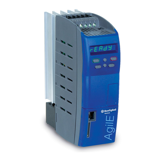
BONFIGLIOLI Agile Operating Instructions Manual (360 pages)
Frequency inverter 230 V / 400 0.09 kW ... 11 kW
Brand:
BONFIGLIOLI
| Category:
DC Drives
| Size: 17.71 MB
Table of Contents
Content
3
Table of Contents
3
1 General Information about the Documentation
11
This Document
12
Warranty and Liability
12
Obligation
13
Copyright
13
Storage
13
2 General Safety Instructions and Information on Use
14
Terminology
14
Designated Use
15
Misuse
15
Explosion Protection
15
Residual Risks
16
Safety and Warning Signs at Frequency Inverter
16
Warning Information and Symbols Used in the User Manual
17
Hazard Classes
17
Hazard Symbols
17
Prohibition Signs
17
Personal Safety Equipment
18
Recycling
18
Grounding Symbol
18
ESD Symbol
18
Information Signs
18
Directives and Guidelines to be Adhered to by the Operator
19
Operator's General Plant Documentation
19
Operator's/Operating Staff's Responsibilities
19
Selection and Qualification of Staff
19
General Work Safety
19
Organizational Measures
20
General
20
Use in Combination with Third-Party Products
20
Transport and Storage
20
Handling and Installation
20
Electrical Connections
20
The Five Safety Rules
21
Safe Operation
21
Maintenance and Service/Troubleshooting
22
Final Decommissioning
22
3 Device Overview
23
Inverter Type and Warning Signs on the Device
23
Type Designation
24
Software Version Identification
25
Overview of Components and Connection Terminals
26
Number of Control Terminals
26
4 Mechanical Installation
27
Safety
27
Installation
27
Size 1 (3~:0.18 Kw to 2.2 Kw; 1~: 0.09 Kw to 1.1 Kw)
28
Size 2 (3~: 3.0 Kw to 5.5 Kw; 1~: 1.5 Kw to 2.2 Kw)
29
Size 3 (5.5 Kw to 11.0 Kw)
30
5 Electrical Installation
31
Safety
31
Electrical Connections Overview
32
EMC Information
32
Dimensioning of Conductor Cross-Section
34
Typical Cross-Sections
35
Mains Connection
36
Motor Connection
38
Length of Motor Cables, Without Filter
39
Motor Cable Length, with Output Filter Du/Dt
40
Motor Cable Length, with Sinus Filter
40
Group Drive
40
Brake Resistor
41
Control Terminals Standard Connection
43
Circuit for Control Via Control Terminals
46
Circuit for Control Via Operator Panel
46
Further Setting Options for Control Terminals
47
Evaluation Logic of Digital Inputs
48
Overview of Voltage Inputs and Outputs
49
External DC 24 V Power Supply
49
Installation Notes According to Ul508C
50
6 Commissioning
51
Operator Panel
52
Menus
52
Selection of Data Sets
54
Menu for Communication Setup
55
Motor Control with Operator Panel
56
Set a Parameter to the Factory Setting
60
Restrict the Scope of Operation
60
First Commissioning
60
Overview
61
Start First Commissioning of an Asynchronous Motor
61
Start First Commissioning of a Synchronous Motor
65
Status Messages During Commissioning (SS
68
Warnings During Commissioning (SA
68
Error Messages During Commissioning (SF
70
Check Direction of Rotation
71
Selection of Actual Value Display
71
Commissioning Without Setup
72
Optional Optimization of Motor Characteristics
72
Speed Controller: Softer Set up
72
Speed Controller: Stronger Set up
72
Voltage Constant
73
Insufficient Torque During Start of FOC and SYNCH
73
Cross Coupling Compensation
73
Commissioning of a Communication Interface
74
After First Commissioning
80
Typical Functions
91
Error Acknowledgment Via Keypad
98
Applications
99
Pump
99
Fan
100
Fan or Pump with Closed Control Loop
101
Fan for Heating, Ventilation, Air Conditioning System
103
Conveying Plant
104
Compressor
105
Travel Applications
106
Torque Control
107
Set-Up Via the Communication Interface
108
7 Parameter Descriptions
110
Inverter Data
110
Control Level
110
Configuration
111
Set Password
112
Programming
113
Machine Data
113
Rated Motor Parameters
113
Further Motor Parameters
114
Device Test
117
Earth Fault and Short Circuit Test (Test 1)
117
Load Test (Test 2)
118
Start Device Test Via Operator Panel
120
Start Device Test Via Control Software or Bus System
120
Automatic Device Test after Error Switch-Off
121
Fan Test
121
Operational Behavior
122
Control
122
Starting Behavior
123
Stopping Behavior
127
Auto Start
129
Flying Start
129
Direct Current Brake
131
Positioning
132
Error and Warning Behavior
135
Overload Ixt
135
Temperature
136
Controller Status
136
Frequency Switch-Off Limit
137
External Error
137
Motor Temperature
137
Technical Demands on Measuring Resistors
140
Phase Failure
141
Automatic Error Acknowledgment
142
Reference Values
142
Reference Frequency Channel
142
Limits
145
Positive and Negative Reference Frequencies
145
Fixed Frequencies
146
Ramps
147
Blocking Frequencies
150
JOG Frequency
151
Reference Percentage Channel
151
Limits
154
Positive and Negative Reference Percentages
154
Fixed Percentages
154
Ramps
155
Motor Potentiometer
156
Operation Modes of Motor Potentiometer
156
Ramp of Motor Potentiometer
156
Motor Potentiometer Via Digital Inputs
157
Keypad Motorpoti: Control Via Operator Panel
160
Electronic Gear
163
Scope of Function
163
Operation Modes of Electronic Gear
163
Gear Factor
165
Offset
166
Actual Values
166
Adjustment Options
166
Control Inputs and Outputs
168
Multifunction Input MFI1
168
Multifunction Input Set as Analog Input MFI1A
169
Multifunction Input Set as Digital Input MFI1D
174
Multifunction Input MFI2
175
Multifunction Input Set as Analog Input MFI2A
175
Multifunction Input Set as Digital Input MFI2D
181
Multifunction Output MFO1
182
Digital Input/Output IN3D/OUT3D
186
Digital Outputs
187
Digital Message
189
Setting Frequency
190
Reference Value Reached
190
Flux Forming Finished
191
Release Brake
192
Current Limitation
192
External Fan
192
Warning Mask
192
Warning Mask, Application
195
Digital Inputs
196
List of Control Signals
197
Start Command
200
3-Wire Control
200
Motor Potentiometer
201
Fixed Frequency Changeover
201
Fixed Percentage Changeover
201
Jog Start
202
Error Acknowledgment
202
Thermal Contact
202
N-/T-Control Changeover
203
Dataset Changeover
203
Handshake Traverse
204
Brake Chopper Release
204
User Warning
204
External Error
205
Plc
205
Multiplexer/Demultiplexer
205
Input Pwm/Repetition Frequency/Pulse Train
207
PWM Input
208
Repetition Frequency Input
209
Pulse Train
209
Further Setting Options
211
V/F Characteristic
211
Linear V/F Characteristic
211
Dynamic Voltage Pre-Control
213
Control Functions
213
Intelligent Current Limits
213
Voltage Controller
215
PID Controller (Technology Controller)
220
Functions of Sensorless Control
227
Slip Compensation
227
Current Limit Value Controller
228
Functions of Field-Orientated Control
229
Current Controller
229
Torque Controller
231
Speed Controller
233
Acceleration Pre-Control
236
Field Controller
237
Modulation Controller
238
Real-Time Tuning (Optimizing Motor Parameters in Operation)
239
Special Functions
240
Pulse Width Modulation
240
Fan
241
Standby Mode and Energy Saving Function
241
Brake Chopper and Brake Resistor
242
Dimensioning of Brake Resistor
243
Motor Chopper
244
Motor Protection
245
Motor Protection by Motor Circuit Breaker
245
Motor Protection by I 2 T- Monitoring
246
Motor Protection by I
248
T- Monitoring
248
V-Belt Monitoring
250
Traverse Function
250
System Data
253
Service Interval Monitoring
253
Copy Parameters
253
Copying Using the Operator Panel
254
Copying Using the PC Control Software
256
Converter Profibus From/To Internal Notation
256
8 Energy Saving
257
Energy Saving Function
257
Quadratic V/F Characteristic
259
Standby Mode
260
Further Energy Saving Options
263
9 Actual Values
265
Actual Values of Frequency Inverter
265
STO Status
267
Actual Values of Machine
267
Actual Values of the System
268
Actual System Value
268
Actual Value Memory
268
Actual Values of the CAN System Bus
270
Actual Values Canopen
270
Actual Values Modbus and Vabus
270
Actual Values Ethernet
270
10 Service
271
Safety
271
Regular Service Work
271
Monitoring of Service Interval
273
DC-Link
273
Fan
274
Reset Service Interval
276
11 Technical Data
277
General Technical Data
277
Device Data
278
AGL202 (3~:0.18 to 0.55 Kw, 1~:0.09 to 0.25 Kw, 230 V)
279
AGL202 (3~:0.75 to 2.2 Kw, 1~:0.37 to 1.1 Kw, 230 V)
280
AGL202 (3~:3.0 to 4.0 Kw, 1~:1.5 to 2.2 Kw, 230 V)
281
AGL202 (3~:5.5 to 7.5 Kw, 1~:3.0 Kw, 230 V)
282
AGL402 (0.25 to 2.2 Kw)
283
AGL402 (3.0 to 11.0 Kw)
284
Increase of Switching Frequency
285
Control Electronics
286
Operation Diagrams
288
12 Options
290
Safety
290
Shield Sheets
290
Shield Sheet for Control Cables
290
Dimensions
292
Shield Sheet for Motor Cables
293
Size 1 and 2 (3~: 0.18 Kw to 5.5 Kw; 1~: 0.09 Kw to 2.2 Kw)
293
Size 3 (3~: 5.5 Kw to 11.0 Kw; 1~: 3Kw)
294
Brake Resistor
295
Devices
296
Line Choke
297
1X230 V Connection
297
3X230 V Connection
298
3X400 V Connection
298
Dimensions
299
Input Filter
300
Footprint Filter
300
Booktype Filter
302
Interference Suppression Class
303
AC 3X400 V
303
AC 3X230 V
305
AC 1X230 V
306
Communication Module
307
USB Adaptor
307
Resource Pack
307
Assembly Variants
308
Feed-Through Assembly (this Assembly Set Is Not Included in Delivery.)
309
Cooling Air Flow Rate Required and Energy Dissipation
309
Size 1 (3~: 0.18 Kw to 2.2 Kw; 1~: 0.09 Kw to 1.1 Kw)
310
Size 2 (3~: 3.0 Kw to 5.5 Kw; 1~: 1.5 Kw to 2.2 Kw)
311
Size 3 (5.5 Kw to 11.0 Kw)
312
Cold Plate (this Assembly Set Is Not Included in Delivery.)
314
Range of Application
314
Required Thermal Properties of the External Heat Sink
314
Additional Fan or Liquid Cooling
316
Application Notes
316
Assembly
317
Vibration-Proof (this Assembly Set Is Not Included in Delivery.)
321
Size 1 (3~: 0.18 Kw to 2.2 Kw; 1~: 0.09 Kw to 1.1 Kw)
321
Size 2 (3~: 3.0 Kw to 5.5 Kw; 1.5 Kw to 2.2 Kw)
322
Size 3 (3~: 5.5 Kw to 11.0 Kw)
323
DIN Rail (this Assembly Set Is Not Included in Delivery.)
324
Size 1 (3~: 0.18 Kw to 2.2 Kw; 1~: 0.09 Kw to 1.1 Kw)
324
13 Error Protocol
325
Error List
325
Error Messages
326
Error Environment
329
Troubleshooting
331
14 Operational and Error Diagnosis
335
Status of Digital Signals
335
Controller Status
335
Warning Status and Warning Status Application
336
15 Parameter List
339
Actual Values (Menu Actual)
339
Parameters (Menu PARA)
343
Index
354
Advertisement
BONFIGLIOLI Agile Applications Manual (166 pages)
Brand:
BONFIGLIOLI
| Category:
DC Drives
| Size: 4.4 MB
Table of Contents
Table of Contents
4
1 General Safety Instructions and Information on Use
9
General Information
9
Purpose of the Frequency Inverters
9
Transport and Storage
9
Handling and Installation
10
Electrical Installation
10
Information on Use
11
Using External Products
11
Maintenance and Service
11
Disposal
11
2 Description of System VPLC
12
Chronological Processing
13
Creating a Program with Function Blocks
14
Starting VPLC
14
Saving a File
14
Function Block (Instruction)
14
Wire
14
Digital Input Block
15
Analog Input Block
15
Digital Output Block
15
Analog Output Block
16
Example
16
Syntax Check
16
Translation and Download (to Frequency Inverter)
16
Starting the PLC
16
Stopping the PLC
16
User Environment
17
Tool Bar and Menu Commands
17
Other Menu Commands
18
Editor
19
Library
19
Properties
19
Settings: Inputs, Outputs and Function Block
20
Starting the PLC Functions
23
Principle for Digital Functions (Input Settings [Boolean])
23
Principle for Analog Functions
25
Input Buffer and Output Buffer for Digital Signals
27
Input Buffer and Output Buffer for Analog Signals
27
Fixed Analog Values
29
3 Overview of Instructions
30
Inputs and Outputs
37
Inputs of Digital Functions
37
Inputs and Outputs of Analog Functions
38
Combination of Inputs and Outputs of Instructions
40
Inputs
40
Combining Input Buffer with Inputs
43
Digital
43
Analog
43
Combining Instructions with One Another
44
Activating Device Functions Via the Output Buffer
44
Controlling a Digital Output Via the Output Buffer
46
Controlling an Analog Output Via the Output Buffer
47
4 Description of Digital Functions
48
Superior/Master
49
P1 and P2 for Chronological Behavior and Jump Target
49
Chronological Behavior
50
Jump Target
50
Overview Table
50
Boolean Operations
51
1] and Operation
52
2] or Operation
52
3] XOR 1 Operation
53
4] XOR 1||3 Operation
53
Flip-Flop Types
54
10] RS-Flip-Flop, Superior
54
110] RS-Flip-Flop, Master
55
20] Toggle-Flip-Flop, Superior
56
120] Toggle-Flip-Flop, Master
57
30] D-Flip-Flop, Superior
58
130] D-Flip-Flop, Master
59
Delays
60
40,41,42] Delay (Retriggerable), Superior
63
140,141,142] Delay (Retriggerable), Master
64
50,51,52] Delay (Non-Retriggerable), Superior
65
150,151,152] Delay (Non-Retriggerable), Master
66
Timer Functions
67
60,61,62] Monoflop (Retriggerable), Superior
67
160,161,162] Monoflop (Retriggerable), Master
68
70,71,72] Monoflop (Non-Retriggerable), Superior
69
170,171,172] Monoflop (Non-Retriggerable), Master
70
80,81,82] Clock Generator Superior
71
180,181,182] Clock Generator, Master
72
Digital Multiplexer
73
Digital Multiplexer (Data Set Number)
73
Switch
73
Switch Data Set
73
Error Functions
74
Triggering of an Error
74
Acknowledging an Error
75
Debouncer
76
No Operation
76
99] NOP (no Operation)
76
Jump Functions
77
100] Jump Function
77
101] Jump Function for Loops
78
5 Description of Analog Functions
79
Behavior
79
Comparators
80
301,302] Comparator (Comparison of Two Variables)
80
303,304] Comparator (Comparison of Constant to Variable)
81
308] Comparator for Motion Blocks
83
Position Comparator (Long)
84
Analog Hysteresis
85
311,312] Window Comparator (Comparison of Two Variables)
86
313,314] Window Comparator (Comparison of Constant to Variable)
87
320] Min/Max
89
Min / Max for Position Values (Long)
89
322] Min/Max in Time Window
90
323] Min/Max for Positions (Long) in Time Window
90
Mathematical Functions
92
Addition and Subtraction
93
Add. O1=-O2=I1+I2-I3+P1-P2
93
331] Addition Position with Offset
93
Multiplication
94
333] Multiplication, Long Result
94
334] Mult. by Fraction
95
335] Mult. Long * Percent
95
Division
96
337] Division by Constant
97
338] Division P1 by I1, Reciprocal
97
Multiplication and Division
98
Average Function
98
Absolute Value of Two Orthogonal Components (2 D Vector)
99
Absolute Value of Three Orthogonal Components (3 D Vector)
99
350] Integrator
100
351] Differentiator (D-Element)
101
360] Absolute Value Function
101
361] X², Sqr (I1)
102
362] X³, (Cube (I1)
102
363] √X, Square Root of I1
102
364] Modulo
103
Controller
104
370] P Controller
104
PI Controller (Tn in Milliseconds)
105
PI Controller (Tn in Seconds)
105
373] PD(T1) Controller
106
374] PID(T1) Controller (Tn in Milliseconds)
106
375] PID(T1) Controller (Tn in Seconds)
107
Filters
109
380] PT1 Element
109
381] Time Average
109
382] Ramp Limitation
110
383] Spike Filter (Average of Three)
111
Analog Switch
112
Analog Multiplexer (Data Set Number)
112
Analog Changeover Switch
112
MUX for Position Values (Data Set Number), Multiplexer
113
Changeover Switch for Position Values (Long)
113
Parameter Access
114
Writing Parameters
114
Write Frequency Parameter
114
402] Write Current Parameter
115
403] Write Voltage Parameter (Eff.)
115
404] Write Voltage Parameter (Peak)
116
405] Write Percentage Parameter
116
406] Write Position Parameter
116
407] Write Long Parameter
117
408] Write Word Parameter
117
Reading Parameters
118
421] Read Frequency Parameter
118
422] Read Current Parameter
118
423] Read Voltage Parameter (Eff.)
119
424] Read Voltage Parameter (Peak)
119
425] Read Percent Parameter
119
426] Read Position Parameter
119
427] Read Long Parameter
120
428] Read Word Parameter
120
Limiters
120
440] Limiter (Const.)
120
441] Limiter (Variable)
121
Counters
121
450] Up/Down Counter with Analog Output
121
451] Stopwatch with Analog Output
122
Positioning Functions
123
501] Start Motion Block as Single Motion
124
502] Start Motion Block in Automatic Mode
125
503] Stop Motion Block
125
504] Continue Motion Block
126
505] Resume Motion Block
126
506] Start Homing
127
507] Check State
127
Bit Functions for Analog Input Values
128
200] Bit NOT Operation
128
201] Bit AND/NAND Operation
129
202] Bit OR/NOR Operation
130
203] Bit XOR/XNOR Operation
131
210] Bit Shift Right
131
211] Bit Arithmetical Shift Right
132
212] Bit Shift Left
132
213] Bit Roll Right
133
220] Output One Bit
133
221] Unite Four Bits to Form a Word
134
222] Add Two Bits to a Word
135
6 Examples of Combinations in the Function Table
136
Write Index and Read Index
136
Write Index and Read Index for FT-Instructions
136
Write Index and Read Index for the Digital Input Buffer
137
Write Index and Read Index for the Analog Input Buffer and FT Fixed Values
138
Run/Stop
139
Example Run/Stop
140
Example 1: Combining Two Digital Outputs
140
Example 2: Combining Several FT-Instructions
141
Example 3: Parameterization of Logic Diagram
144
7 Actual Values, Output Signals and Messages
145
Actual Values of Digital Functions
145
Actual Values of Analog Functions
147
Signals for Digital Outputs of Device
148
Signals for Analog Outputs of Device
148
Signal Sources for Device Function
149
Error Messages of Instruction "95 - Triggering an Error
149
8 Operation as State Machine
150
Example of a Controller
150
9 List of Parameters
157
Actual Values
157
Parameters of Function Table
158
10 Annex
160
Mask: Diagram for Digital Instructions of Function Table
160
Mask: Functions Settings
161
Index
162
BONFIGLIOLI Agile Applications Manual (44 pages)
Brand:
BONFIGLIOLI
| Category:
DC Drives
| Size: 4.03 MB
Table of Contents
Table of Contents
3
1 General Information about the Documentation
5
Instruction Manuals
5
This Document
5
Warranty and Liability
6
Obligation
6
Copyright
6
Storage
6
2 General Safety Instructions and Information on Use
7
Terminology
7
Designated Use
7
Misuse
7
Residual Risks
8
Safety and Warning Signs on Frequency Inverter
8
Warning Information and Symbols Used in the Operating Instructions
9
Hazard Classes
9
Hazard Symbols
9
Prohibition Signs
9
Personal Safety Equipment
9
Recycling
9
Grounding Symbol
9
ESD Symbol
10
Information Signs
10
Font Style in Documentation
10
Directives and Guidelines to be Adhered to by the Operator
10
Operator's/Operating Staff's Responsibilities
10
Selection and Qualification of Staff
10
General Work Safety
10
Ear Protectors
11
Organizational Measures
11
General
11
Use in Combination with Third-Party Products
11
Handling and Installation
11
Electrical Connections
11
Safe Operation
12
Maintenance and Service/Troubleshooting
12
Final Decommissioning
12
3 Safety Instructions on Function "Safe Torque Off" (STO)
14
Approved Devices
15
Connection 3X AC 400/480 V
15
Connection 1X AC 230 V / 3X AC 230 V
15
4 Information of Risk Analysis and Risk Assessment
16
5 General Description of Safety Function
17
Integrated Safety Function
17
Functional Safety
17
Classification the Safety Requirement
17
6 Description of ACTIVE Cube Safety Function
18
Definitions of the AGL Safety Functions
18
Specification of the Safety Function 1 (SF1): STO
18
Specification of the Safety Function 2 (SF2): SS1
19
Description of Safety Function
20
Two-Channel Monitoring
21
Diagnosis Function and Enforced Dynamizing
23
7 Requirements to be Met by Installation
24
Instructions on Installation of Safety Equipment
24
External Safety Control Equipment
24
External DC 24 V Power Supply
25
External DC 24 V Voltage Supply for Group Stop
25
DC 24 V Power Supply by AGL
25
8 Requirements to be Met in Operation
25
9 Requirements to be Met by Acceptance Inspection
26
10 Application Examples
27
STO According to Stop Category 0
27
STO Direct Stop
27
STO Direct Stop with Error Exclusion "Short Circuit" in the Cabinet
28
STO Direct Stop with Feedback to PLC
29
STO Direct Stop W/ Feedback to PLC W/ Error Exclusion "Short Circuit" in Cabinet
30
SS1 According to Stop Category 1
31
SS1 Direct Stop
31
SS1 Direct Stop with Error Exclusion "Short Circuit" in the Cabinet
32
SS1 Direct Stop with Feedback to PLC
33
SS1 Direct Stop W/ Feedback to PLC W/ Error Exclusion "Short Circuit" in Cabinet
34
Internal DC 24 V Supply, SS1
35
Group Stop, SS 1
36
Checklist
37
11 Safety Function Test Report
39
Characteristical Data
39
12 STO Status (Diagnosis)
39
13 Change Index
40
Advertisement
Advertisement
Related Products
BONFIGLIOLI agl 202
BONFIGLIOLI agl 402
BONFIGLIOLI Agile Series
BONFIGLIOLI AGL402-3-S Series
BONFIGLIOLI AGL402-1-S Series
BONFIGLIOLI AGL402-2-S Series
BONFIGLIOLI AGL202-2-S Series
BONFIGLIOLI AGL202-1-S Series
BONFIGLIOLI AGL202-3-S Series
BONFIGLIOLI Agile AGL 401-05
BONFIGLIOLI Categories
DC Drives
Engine
Inverter
Industrial Equipment
Controller
More BONFIGLIOLI Manuals
Login
Sign In
OR
Sign in with Facebook
Sign in with Google
Upload manual
Upload from disk
Upload from URL