
Related Manuals for Kidde ARIES


Summary of Contents for Kidde ARIES
- Page 1 P/N 06-236530-001 August 2013 ARIES™ Fire Alarm/Suppression Control Unit Installation, Operation, and Maintenance Manual LISTED UL Listing File No. S2422 FM Approvals...
-
Page 3: Foreword
Fenwal believes this data to be accurate, but it is published and presented without any guarantee or warranty whatsoever. Kidde-Fenwal disclaims any liability for any use that may be made of the data and information contained herein by any and all other parties. -
Page 4: Terms And Abbreviations
Addressable Alarmline Module AAM: LCD: Liquid Crystal Display Alternating Current LED: Light Emitting Diode ACT: ARIES Configuration Tool MEA: Materials and Equipment Acceptance Division of the City of New York NAC: Notification Appliance Circuit ADA: Americans with Disabilities Act Ampere Hour N.C.:... -
Page 5: Safety Summary
SAFETY SUMMARY This entire manual must be read and understood before installation. Installation Precautions Adherence to the following will aid in problem-free installation with long- term reliability: Several different sources of power can be connected to this fire alarm control unit. WARNING Disconnect all sources of power before servicing. - Page 6 SAFETY SUMMARY (CONT.) another level or floor of a building. A second floor detector, for example, may not sense a first floor or basement fire. Furthermore, all types of smoke detectors, both ionization and photoelectric types, have sensing limitations. No type of smoke detector can sense every kind of fire caused by carelessness and safety hazards such as smoking in bed, violent explosions, escaping gas, improper storage of flammable materials, overloaded electrical circuits, children playing with matches, or arson.
- Page 7 CAUTIONS AND WARNINGS A caution identifies a procedure, practice, or statement, which, if not strictly CAUTION followed, could result in programming errors, impairment of equipment operation, or equipment damage. A warning identifies an operating or maintenance procedure, practice, condition or statement, which, if not strictly followed, could result in personal WARNING injury or death.
- Page 8 NOTICE TO USERS, INSTALLERS, AUTHORITIES HAVING JURISDICTION AND ALL OTHER INVOLVED PARTIES This product incorporates field-programmable software. In order for the product to comply with the require- ments in the Standard for Control Units and Accessories for Fire Alarm Systems, UL 864, certain programming features or options must be limited to specific values or not used at all as indicated below: Program Feature or Option Permitted in...
-
Page 9: Table Of Contents
1-2.1.2 Operator Control Keys ................1-4 1-2.1.3 Digit and Functionality Keys ..............1-4 1-2.2 Printed-Circuit Board (PCB) ..............1-4 1-2.3 ARIES Cabinet ..................1-6 1-2.4 Power-Supply/Battery-Charger Assembly ..........1-6 1-2.4.1 Batteries....................1-7 Optional Devices ................... 1-7 1-3.1 Remote Display/Control Module (RDCM)........... 1-7 1-3.2... -
Page 10: Table Of Contents
Installation Overview................2-3 2-3.1 Step One: Installing the Control Unit Back Box and Preparing Electrical Wiring2-3 2-3.2 Step Two: Installing the ARIES Power Supply and Main PCB ....... 2-3 2-3.3 Step Three: Connecting AC Power and Standby Battery ......2-3 2-3.4 Step Four: Auto-Configuring the System .......... - Page 11 2-17.2 Network Wiring..................2-31 2-18 Fiber-Optic Converter Card..............2-34 2-19 Intelligent Interface Module..............2-39 CHAPTER 3 SYSTEM OPERATIONS ARIES System Operations Overview ............3-1 System Operation ................. 3-1 3-2.1 Operating States................... 3-1 3-2.2 Outputs Activation ................3-2 3-2.3 Operator Keys ..................3-2 3-2.4...
- Page 12 TABLE OF CONTENTS (CONT.) 3-2.5.6.2 How To Reset the Control Unit After a Supervisory Condition ...... 3-107 3-2.5.7 Pre-Alarm State..................3-108 3-2.5.7.1 What to Do When a Pre-Alarm Occurs............3-109 3-2.5.7.2 Pre-Alarm Silencing................3-109 3-2.5.7.3 How to Reset the Control Unit After a Pre-Alarm Condition ......3-109 3-2.5.8 Concurrent States .................
- Page 13 TABLE OF CONTENTS (CONT.) 3-3.20 How Concurrent Remote Events Will Be Displayed ........3-134 3-3.20.1 Remote Level-1 Event Display ..............3-134 3-3.20.2 Remote Level-2 Event Display ..............3-136 3-3.20.3 Remote Level-3 and Lower-Level Event Display......... 3-137 3-3.21 Network Start-Up.................. 3-137 3-3.21.1 Special Procedures for Networked Systems..........
- Page 14 THIS PAGE INTENTIONALLY LEFT BLANK. August 2013 P/N 06-236530-001...
-
Page 15: List Of Figures
Figure Name Page Number Typical ARIES System ..................1-1 ARIES Display ..................... 1-3 ARIES Control Unit Printed Circuit Board ..............1-5 ARIES Cabinet ..................... 1-6 Power-Supply Assembly..................1-7 Remote Display/Control Module ................1-7 Model ATM-R Relay Driver Module ................1-8 Network Interface Card (shown mounted to PCB) ............. - Page 16 Interconnection of IIM ..................2-39 Display Panel ...................... 3-2 Normal Operation Display ..................3-5 Main Menu Functions.................... 3-6 ARIES Menu Functions and Top-Level Displays............3-7 Menu Functions ....................3-9 Menu Functions Cont.................... 3-11 Typical Trouble Message Display ................3-97 Typical Message After Trouble Manual Scroll Cycle............
- Page 17 Programming Sub-Menu ..................3-121 3-54 Typical Auto-Learn In-Process Display ..............3-122 3-55 Typical Auto-Learn Complete Display ..............3-122 3-56 Typical Networked ARIES System................3-124 3-57 Network Node Prompt ..................3-126 3-58 Top-level Menu Selections..................3-126 3-59 Networked Control-Unit Interactions............... 3-128 3-60 Network Normal Message Display................
- Page 18 Agent Release Circuits for XV Control System (P/N 87-120099-001 and 87-120099-002) and CXV Control System (P/N 93-487100-001)C-2 Agent Release Circuit Wiring - Initiators, Non-Power-Limited ........C-3 Power-Limited and Non-Power-Limited Wiring............E-2 Typical ARIES and DACT Interconnections ............... F-1 ARIES and Silent Knight Model 5104 DACT Interconnections........F-2 August 2013 P/N 06-236530-001...
- Page 19 Main Menu Functions and Descriptions ..............3-6 Password Levels and Descriptions ................3-97 ARIES Password Levels..................3-97 Progressive Alarm States of a ARIES System(Designed for Property Protection/Mission Continuity) ......................3-111 Priority Levels for Different Types of Concurrent Events ..........3-112 General System Events..................
- Page 20 THIS PAGE INTENTIONALLY LEFT BLANK. August 2013 xviii P/N 06-236530-001...
-
Page 21: List Of Appendices
LIST OF APPENDICES APPENDIX A Battery Calculations ......................A-1 APPENDIX B Wiring Requirements for ARIES Signaling Line Circuit ............B-1 APPENDIX C Listed and Approved Releasing Devices................C-1 APPENDIX D Device-Programmer Operating Instructions ................D-1 APPENDIX E Routings for Power-Limited and Non-Power-Limited Wiring ............. E-1 APPENDIX F Central-Station Operation .................... - Page 22 THIS PAGE INTENTIONALLY LEFT BLANK. August 2013 P/N 06-236530-001...
-
Page 23: Chapter 1 System Overview
(hereinafter referred to as the display) is mounted to the PCB for system status and user operation. The ARIES has one signaling line circuit (SLC) that can communicate with up to 255 intelligent devices. See Figure 1-1 for a typical fire suppression system application. -
Page 24: 1-1.1 Standard Features
The ARIES coordinates the operations of the varied components of a protected-premises fire protection or notification system. These operations include: • Interpreting initiating signals from automatic detectors or monitor modules. Initiating signals can be any of the following: – Automatic detector pre-alarm –... -
Page 25: Control Unit Components
@ 24 Vdc to support the basic control unit and its associated peripheral devices and to charge the standby battery. The switching power supply is user-configurable to operate from either 120 or 240 Vac, 50/60 Hz primary power. CONTROL UNIT COMPONENTS The ARIES System includes: • Display •... -
Page 26: Operator Control Keys
1-2.2 Printed-Circuit Board (PCB) The ARIES’s Printed Circuit Board (PCB) contains the system’s central processing unit (CPU) and all of the primary circuits. The PCB is packaged separately and shipped inside the control-unit's enclosure. Figure 1-3 shows the layout of the PCB, including terminals for external components, the operator interface, and connectors. - Page 27 (TB11) Notification-Appliance 24 VDC Auxiliary-Power Circuit No. 1 Terminals (TB2) (TB7) Note: Polarities shown reflect the condition when the circuit is either active or in the alarm state. Figure 1-3. ARIES Control Unit Printed Circuit Board P/N 06-236530-001 August 2013...
-
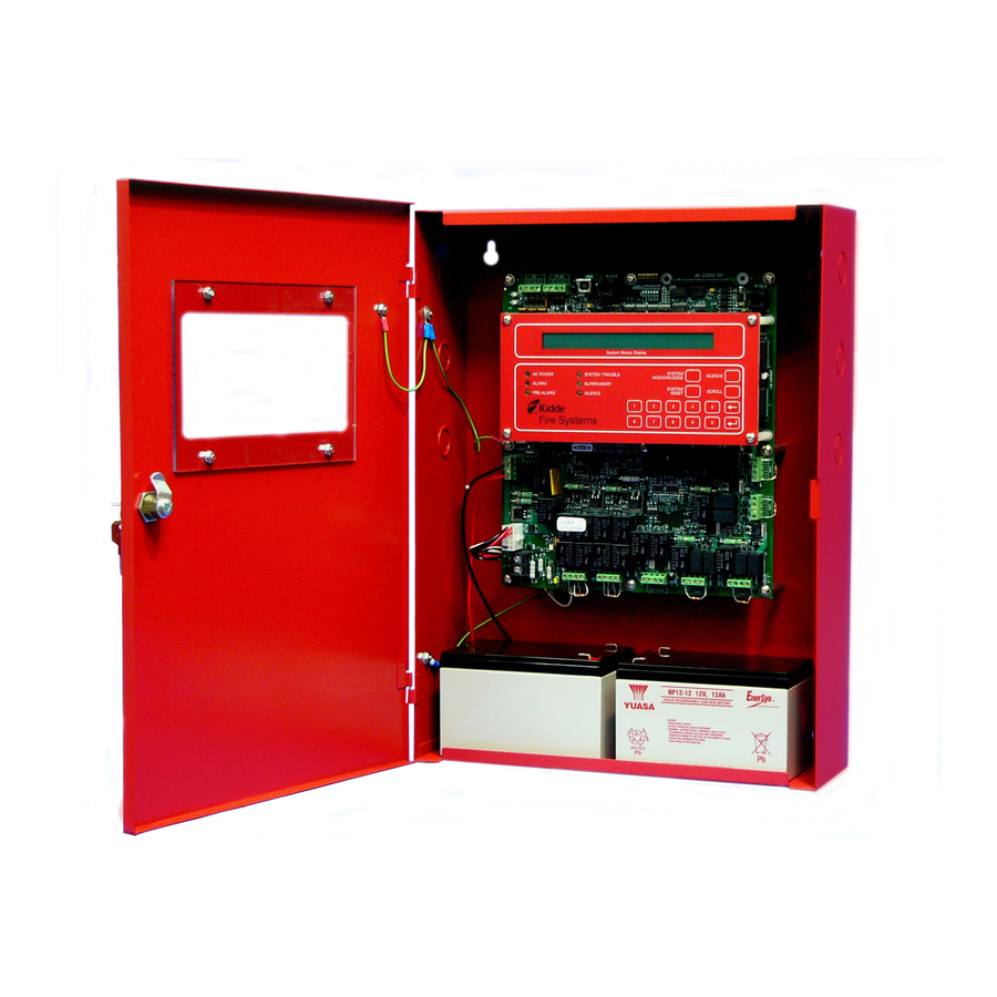
Page 28: Aries Cabinet
The power supply/battery-charger assembly can charge standby batteries of up to 70 AH capacity. The power-supply/battery-charger assembly is packaged separately and shipped inside the control unit’s enclosure. Figure 1-5 shows the placement of the power- supply/battery-charger assembly in the ARIES’s back box. August 2013 P/N 06-236530-001... -
Page 29: Batteries
The remote display control module permits system events to be displayed, and operator intervention to be accomplished, from more than one location in a facility. Remote display control module, Model RDCM, is a duplicate of the ARIES’s Display/Control Module and allows full operator intervention and system control. -
Page 30: Atm Series Driver Modules
ATM Series Driver Modules The ATM Series Driver Modules permit third-party graphical annunciators and large numbers of auxiliary relays to be used with the ARIES. Two types of driver modules can be used, Models ATM-L and ATM-R. The ARIES supports up to 16 ATM-L or ATM-R Driver Modules, or any combination of these two modules, together with RDCMs, that does not exceed 31 total addresses. -
Page 31: Intelligent Interface Module (Iim)
77.100) for a complete description of the Intelligent Interface Module. 8" 2-9/32" 5-1/2" 9/32" Diameter Module Latch 8" Ground KIDDE-FENWAL, INC. 400 MAIN STREET, ASHLAND, MA 01721 TEL: (508) 881-2000 FAX: (508) 881-8920 MODEL: IIM-2000 CAT. NO. 89-100083-001 1-1/4" 1-1/16" Front View with Door Open ½" & ¾"... -
Page 32: Trim Ring
Each detector continuously transmits its current status to the ARIES through the signaling line circuit, and responds to control unit polling and inquiries by the address that is set in the detector using the Handheld Programmer, P/N 74-200013-001, or using the ARIES’s display. -
Page 33: Smartone Ionization Smoke Detector, Model Cpd-7052
They are also used in special extinguishing systems as one criterion to release the extinguishing agent. See Figure 1-12. Note: Older-style Model CPD-7040 Ionization Detectors may be used with the ARIES Control Unit. Figure 1-12. SmartOne™ Smoke Detector 1-4.2... -
Page 34: Detector Bases
1-4.4 Detector Bases Two detector bases are available. 1-4.4.1 FLANGED DETECTOR BASE, MODEL 6SB The Model 6SB Detector Base is used in applications where the detector's installed appearance is a primary consideration. This base mounts to standard 3-, 3½-, and 4-inch electrical boxes. Figure 1-14. -
Page 35: 1-4.6 Duct Housing, Model Dh-2000
Control Modules. These modules provide a uniquely-identifiable interface between the ARIES and conventional notification appliances such as horns and strobes. Each addressable module continuously transmits its current status to the ARIES Control Unit via the signaling line circuit, and responds to control unit polling, inquiries, and activation commands by the address that is set in the module using the Handheld Programmer, P/N 74-200013-001, or using the ARIES’s display. -
Page 36: 1-5.2 Orion-Xt Interface Module, Model Palm
The Model PALM ORION-XT Interface Module is a monitor module that enables a High Sensitivity Smoke Detector (HSSD) to report pre-alarm, alarm, and trouble signals to the ARIES Control Unit via its signaling line circuit. The AIM mounts inside the ORION-XT detector housing. -
Page 37: Addressable Relay Module, Model Ao
Hand-Held Programmer. A maximum of 64 RRMs can be activated consecutively via the ARIES Control Panel. Up to 16 RRMs can be configured in a group for simultaneous activation. The ARIES SLC can support up to 4 groups. The RRM is intended for indoor dry location use, and is available in two models, one for mounting in a standard electrical box and a second model for mounting in suitable UL- 864 Listed cabinets. - Page 38 When Installing the RRM, refer to the RRM Installaton Sheet. Also, see Paragraph 2-11 for the release circuit wiring instructions, and Appendix E for rating guidelines for power-limited and non power-limited wiring. For configuration instructions, refer to the ARIES Configuration Software User’s Guide (P/N 06-236530-002).
-
Page 39: Isolator Modules
ISOLATOR MODULES Isolator modules are automatic switches that open a segment of the signaling line circuit when a short-circuit fault is detected in that segment. The remainder of the signaling line circuit continues to function normally and is unaffected by the short-circuit fault. The isolator modules will close and resume normal operation when the short-circuit fault is removed. -
Page 40: Specifications
The electrical specifications for the ARIES are as follows: 1-7.1.1 PRIMARY AC POWER Primary AC connections are made through AC input-power terminals, TB 13, on the ARIES main PCB. Wire size is #14 AWG minimum with 600 Vac insulation. • 120 Vac, 50/60 Hz, 3.2 A, or •... -
Page 41: 1-7.4 Notification-Appliance And Releasing Circuits
1-7.4 Notification-Appliance and Releasing Circuits All circuits are power-limited except where noted. NAC Rating Regulated 24 Vdc NAC Wiring Class A, Style Z Class B, Style Y Note: NACs suitable for synchronized and non-synchronized notification appliances. Use polarized notification appliances only. The maximum number of synchronized devices is 25. -
Page 42: 1-7.7 Electrical Supervision
1-7.7 Electrical Supervision • A short circuit from any field-wiring terminal (except AC-Power-Input Terminals and Form-C Relay Terminals) to earth ground will create a “Ground-Fault” trouble condition. • An open circuit in the wiring for the SLC, the outputs (NACs, release circuits, and combination circuits), the RS-485 communications circuit, and the battery-charging circuit will create an “Open”... -
Page 43: Preparing For Installation
PREPARING FOR INSTALLATION Complete the following preparation procedures before installing the control unit. 2-1.1 Control-Unit Components Check the contents of the ARIES shipping carton to ensure that you have received the following components: • Enclosure w/Door, P/N 06-220019-002 •... -
Page 44: 2-1.3 Determining Installation Location
It is important that the location of the system be clean, dry, vibration-free, and maintained within the operating limits. CODES AND STANDARDS Use the following codes, standards and practices when installing the ARIES System: • NFPA 70, National Electric Code, Articles –... -
Page 45: Installation Overview
Step Two: Installing the ARIES Power Supply and Main PCB • Install the ARIES power supply and main printed-circuit board. • Dress and connect field wiring to the ARIES Control Unit's main printed-circuit board as shown on the approved system drawings and as illustrated in this manual. 2-3.3 Step Three: Connecting AC Power and Standby Battery Apply AC power, then connect the standby battery. -
Page 46: 2-3.5 Step Five: Uploading The Application Program And Performing The Pre-Test
these procedures and compare this list to the approved set of SLC devices. Correct any inconsistencies and/or trouble messages. 2-3.5 Step Five: Uploading the Application Program and Performing the Pre-Test Upload the site-specific application program, and pre-test the system in accordance with the approved sequence of operation. -
Page 47: Mounting The Cabinet/Enclosure
MOUNTING THE CABINET/ENCLOSURE The control unit can be surface or semi-flush mounted. Figure 2-1 shows the control-unit- enclosure dimensions. All dimensions are in inches. 14.25 13.12 9.12 5.12 1.12 1/2" (0.875 Dia) 3/4" (1.125 Dia) 1.500 Combination Knockouts (4) Located on Top (3) Located In-Line on Two Sides 0.500 Cover Outside... -
Page 48: Preparing The Enclosure For Wall Mounting
2-4.1 Preparing the Enclosure for Wall Mounting For either mounting configuration: 1. Remove the keys from the envelope taped to the top of the enclosure and open the door to the control unit. 2. Disconnect the ground wire that connects the enclosure door to the back box. 3. -
Page 49: 2-4.3 Semi-Flush Mounting
approximately 2 to 3 feet of wire length in the enclosure for future internal connections. 2-4.3 Semi-Flush Mounting To semi-flush mount the control unit: 1. Cut and plumb an opening approximately 14.25” wide by 19” high in the wall on which the control unit will be semi-flush mounted. - Page 50 Wiring-Harness Connections Fastening Tab for Screw WHT/BLK Retention Tabs Typ (2) Ground Wire from Installation Kit Connect to lower earth-ground stud on left- hand side of enclosure. Threaded hole for 3 x 10 mm mounting screw. Wiring-Harness Connections WHT/BLK ATTENTION ! The Control Unit is supplied with one of two equivalent power supplies.
-
Page 51: Installing The Printed Circuit Board (Pcb)
3. Locate the 3 x 10 mm mounting screw in the installation kit and thread it part way into the lower of the two threaded holes of the power supply unit. See Figure 2-4. 4. Ensure that the power supply unit AC-input-voltage selector switch is set to the proper position for either 120 Vac or 220/240 Vac. - Page 52 AC Protective Cover (with standoff) Figure 2-6. PCB Installation 1. Locate the nine (9) 2-1/4” aluminum standoffs in the installation kit and screw one securely into each of the nine (9) threaded PEMs in the back surface of the enclosure. 2.
-
Page 53: Ac And Dc Power Connections
2-7.1 AC Power Connection The primary AC power for the ARIES Control Unit is 120 Vac, 50/60 Hz, 3.2 A or 220/240 Vac, 50/60Hz, 1.6A. The default power configuration is 120 Vac and will require resetting for 220/240 Vac operation. Configuration of primary AC power requires that the... -
Page 54: 2-7.2 Dc Power Connection
supply is installed in the enclosure, and that Switch S4 in the lower-left corner of the printed-circuit board be set to agree with the primary AC power being used. Refer to Paragraph 2-5. Over-current protection for this circuit must comply with Article 760 of the National Electrical Code (NEC) and/or the local electrical code. -
Page 55: Signaling Line Circuit
Figure 2-9. Standby Battery Connections SIGNALING LINE CIRCUIT The signaling line circuit (SLC) is the communications path between the ARIES Control Unit and the SmartOne field devices. The SLC can be wired to meet NFPA 72 Class-A, Style-6 and -7 or Class-B, Style-4 requirements. - Page 56 Jumper Branch 1 Branch 2 Branch N Volt-Ohm Meter Branch 3 Figure 2-10. Measuring Class-B SLC Wiring Resistance The total wiring capacitance cannot exceed 0.5 F. Use the following procedure to determine the wiring capacitance. 1. Ensure that the ends of each branch line are open circuited. 2.
- Page 57 Note: Isolator modules are not required for a Class-B, Style-4 signaling line circuit. A maximum of 30 SmartOne devices can be installed between a pair of isolator modules. Figure 2-12. Class-B, Style-4 Signaling Line Circuit P/N 06-236530-001 2-15 August 2013...
-
Page 58: 2-8.1.2 Class-A, Style-6 Wiring Requirements
2-8.1.2 CLASS-A, STYLE-6 WIRING REQUIREMENTS Note: The following resistance reading MUST be taken PRIOR to the installation of any peripheral device. The total wiring resistance from the start of the “Out” leg to the end of the “Return” leg cannot exceed 40 ohms. Use the following procedure to determine the wiring resistance. - Page 59 Figure 2-15. Class-A, Style-6 Signaling Line Circuit P/N 06-236530-001 2-17 August 2013...
-
Page 60: 2-8.1.3 Special Class-A, Style-7 Requirements
2-8.1.3 SPECIAL CLASS-A, STYLE-7 REQUIREMENTS A Class-A, Style-7 signaling line circuit requires a pair of isolator modules for each SmartOne device as shown in Figure 2-16. Make sure that the SLC-Selector Switch S2 is moved to the right into the Style-6 position. Refer to Figure 1-3. Figure 2-16. -
Page 61: Notification Appliance Circuits
The NS Series notification appliances provide the option to use silenceable horns and non- silenceable strobes on the same NAC. Refer to the ARIES Programmer’s Guide to configure one or both NACs for use with the NS Series notification appliances. -
Page 62: Combination Circuits
2-10 COMBINATION CIRCUITS The ARIES Control Unit has two combination circuits that can be used either as notification- appliance circuits (NACs) or as releasing circuits for solenoid valves. The combination circuits are labeled Combo1 and Combo2. These circuits have field-wiring connections that terminate at TB7 and TB6, respectively. -
Page 63: Combination Circuits Used As Releasing Circuits
P/N 06-220023-001, is wired in series with the solenoid valve. The compatible control heads and solenoid valves are listed in Appendix C. Refer to the ARIES Programmer’s Guide to configure one or both combination circuits as releasing circuits. -
Page 64: Releasing Circuits
(Must be close nippled to solenoid enclosure) Figure 2-22. Combination Circuit used as Releasing Circuit 2-11 RELEASING CIRCUITS The ARIES has two releasing circuits that can be configured to actuate extinguishing systems through any of the following ways: • Single actuator assembly •... -
Page 65: 2-11.2 Releasing Circuits For Single Control Head Or Solenoid Valve
2-11.2 Releasing Circuits for Single Control Head or Solenoid Valve Each releasing circuit can be configured to activate either one Kidde control head or one pre-action-sprinkler or deluge-sprinkler valve. Total current output of the ARIES power supply must not exceed 5.4 A. Figure 2-24 shows a releasing circuit wired for single- control-head or single-solenoid-valve actuation. -
Page 66: Releasing Circuits For Dual Control Heads Or Solenoid Valves
06-220023-001, is wired in series with each of the two control heads or solenoid valves. See Appendix C for compatible control heads and solenoid valves. Refer to the ARIES Programmer’s Guide to configure the releasing circuits for dual-control-head or dual- solenoid-valve actuation. -
Page 67: Rs-485 Communications Circuit
2-13 RS-485 COMMUNICATIONS CIRCUIT The ARIES Control Unit can communicate with up to 31 peripheral devices via its RS-485 communications circuit. The peripheral devices are listed below, along with the maximum numbers for each particular type of device. The total number of peripheral devices cannot exceed 31. - Page 68 The RS-485 communications circuit is power-limited. Figure 2-27 shows typical interconnections among the ARIES Control Unit and the peripheral devices using a single communications channel. Relay 1 Relay 2 Relay 3 Trouble AC IN Style 4 Figure 2-27. Single-Channel RS-485 Wiring to Peripheral Devices...
- Page 69 Figure 2-28 shows typical interconnections among the ARIES Control Unit and the peripheral devices using a dual-channel communications circuit. Relay 1 Relay 2 Relay 3 Trouble AC IN Style 4 Figure 2-28. Dual-Channel RS-485 Wiring to Peripheral Devices P/N 06-236530-001...
-
Page 70: Relays
ARIES Programmer’s Guide. 2-14 RELAYS The ARIES Control Unit has three Form-C, programmable relays and one Form-C, trouble relay as shown in Figure 2-30. All of these relays have the following contact ratings: •... -
Page 71: Rs-232 Communications Port
2-15 RS-232 COMMUNICATIONS PORT The ARIES Control Unit has two RS-232 communications ports (J3/RS232B and J8/RS232A) to connect to the Intelligent Interface Module (IIM) and various third-party supplementary devices such as serial printers and graphical monitoring systems. Note: It is recommended that the RS232B port (J3) be used when only a single RS232 port is necessary. -
Page 72: Usb Communications Port
2-16 USB COMMUNICATIONS PORT The ARIES Control Unit has one USB communications port to act as a device for a laptop computer being used to upload and download a system configuration or to download the event logs. The USB port connects to the laptop computer via a standard USB cable. -
Page 73: How To Install A Nic
How to Install a NIC Refer to Figure 2-33 before you install the NIC and perform the following procedure to install the NIC on the ARIES’s printed-circuit board. Remove AC and DC power from the control unit before you install a NIC. - Page 74 Note: Do not T-Tap the network wiring. Use serial wiring style only. Do not run wiring back from Node N to Node 1. Relay 1 Relay 2 Relay 3 Trouble Relay 1 Relay 2 Relay 3 Trouble AC In AC In Style 4 Style 4 THIS PAGE INTENTIONALLY LEFT BLANK.
- Page 75 Figure 2-35. Class-A, Style-7 Network Wiring P/N 06-236530-001 2-33 August 2013...
-
Page 76: Fiber-Optic Converter Card
2-18 FIBER-OPTIC CONVERTER CARD The Fiber-Optic Converter Card allows networked ARIES Control Units to be interconnected using fiber-optic medium. Use one OCC to terminate each end of a fiber-optic communications- channel(s) segment. The ARIES networking structure supports a mixture of fiber-optic and twisted-wire interconnections among networked control units. - Page 77 Figure 2-36. Typical Single-Channel System using 62.5/125 m Duplex Fiber-Optic Media P/N 06-236530-001 2-35 August 2013...
- Page 78 Figure 2-37 shows the same single-channel system, but using a combination of 62.5/125 m duplex fiber-optic media and twisted, shielded, low-capacitance wiring. Figure 2-37. Typical Single-Channel System using Combination Twisted, Shielded and Fiber-Optic Media August 2013 2-36 P/N 06-236530-001...
- Page 79 Figure 2-38 shows a typical dual-channel system using 62.5/125 m duplex fiber-optic media. Figure 2-38. Typical Dual-Channel System using 62.5/125 m Duplex Fiber Optic Media P/N 06-236530-001 2-37 August 2013...
- Page 80 Figure 2-39 shows the same dual-channel system, but using a combination of 62.5/125 m duplex fiber-optic media and twisted, shielded, low-capacitance wiring. Use ST connectors to attach the fiber-optic media to the OCCs. Figure 2-39. Typical Dual-Channel System using Combination Twisted, Shielded and Fiber Optic Media August 2013 2-38 P/N 06-236530-001...
-
Page 81: Intelligent Interface Module
2-19 INTELLIGENT INTERFACE MODULE The interconnection of the Intelligent Interface Module to the ARIES Control Unit is shown in Figure 2-40. Refer to the ORION-XT Installation, Operation and Maintenance Manual (Publication 77.100) for additional details. Figure 2-40. Interconnection of IIM... - Page 82 THIS PAGE INTENTIONALLY LEFT BLANK. August 2013 2-40 P/N 06-236530-001...
-
Page 83: Chapter 3 System Operations
Guide in P/N 76-600000-008 for instructions on how to program the ARIES System. SYSTEM OPERATION This section instructs the end-user how to operate an ARIES Control Unit, including how to distinguish the different operating states, how to use the operator keys, and what the status indicating LEDs mean. -
Page 84: 3-2.2 Outputs Activation
3-2.3 Operator Keys Operator keys for the ARIES System are located on the display inside the control unit. The control unit door must be open to access the operator keys. Figure 3-1 shows the location of the operator keys and status indicating LEDs on the display. - Page 85 <SILENCE> Key are intentionally ignored. A subsequent key press will only be acted upon after at least 10 seconds have elapsed since the previous key press. <RESET> The <RESET> Key restores the ARIES System to Normal Mode after all alarm system events have been acknowledged and have ceased reporting alarm conditions.
-
Page 86: 3-2.4 Status Indicating Leds
3-2.4 Status Indicating LEDs Table 3-3 lists the names and functions of the system status LEDs on the display. Table 3-3. System Status LEDs and Functions COLOR FUNCTION Power On Green A steady LED indicates primary AC power is on at acceptable levels. An unlit LED indicates unacceptable AC power levels or AC power is disconnected. -
Page 87: 3-2.5 Operating Instructions
Figure 3-2. Normal Operation Display 3-2.5.2 MENU OPERATION The ARIES has a built-in menu structure. This menu structure has been implemented to aid users with system operating functions. The following paragraphs describe the menu structure, how to access the menu, menu functions, and how to exit the menu. -
Page 88: 3-2.5.2.1 Menu Functions
Figure 3-3. Main Menu Functions Table 3-4 lists and provides a brief description of typical functions that can be performed using the ARIES System’s menus. Figure 3-4 contains the ARIES main menu functions and top-level displays. Table 3-4. Main Menu Functions and Descriptions... - Page 89 7. Control Modules 7. Ouput Test 7. HSDs 7. Voltages 8. SLC Resistance 8. HSD Assignments 8. HSDS 9. Battery 9. More Options 9. More Options Level-2 (Installer) Password required. Figure 3-4. ARIES Menu Functions and Top-Level Displays P/N 06-236530-001 August 2013...
- Page 90 THIS PAGE INTENTIONALLY LEFT BLANK. August 2013 P/N 06-236530-001...
- Page 91 System Operations Enter Password Press "0" Key 1. Isolate 7. HSDs 1. SLC Devices 2. Outputs 3. Control Modules 4. Global Isolate 5. Isolate Macro 1 6. Isolate Macro 2 1. ATM 1. ATM 1. NACs 1. Inputs * Isolate SLC Devices Isolate HSDs 1.
- Page 93 System Operations 1. Time / Date 2. Port Control 3. SLC Devices 1. Set Time 5. Blink Control 5. Replace Device 1. Device Addr Change 2. Configuration 3. Registration 4. De-Registration 1. RS232 A * Set Loop Device Address Program Device Blink Control Present SLC Device Address *_ _ (0 - 255) 1.
-
Page 95: Isolate Menu Functions
Purpose: To prevent initiating and trouble signals from selected SmartOne automatic detectors and monitor modules from being processed and acted upon by the ARIES Control Unit. Also to prevent selected SmartOne control and relay modules from carrying out activation instructions issued by the ARIES Control Unit. - Page 96 3-2.5.2.2.2 How to De-Isolate SLC Devices Purpose: To enable the ARIES Control Unit to process initiating and trouble signals from previously-isolated SmartOne automatic detectors and monitor modules. Also to enable previously-isolated SmartOne control and relay modules to execute activation instructions issued by the ARIES Control Unit.
- Page 97 3-2.5.2.2.4 How to De-Isolate Control-Unit-Based Outputs Purpose: To enable previously-isolated control-unit-based outputs to execute activation instructions issued by the ARIES Control Unit. Step Action Result Press 0 Key Initiate menu access Enter Password; Press “Enter” Key Gain access to menus...
- Page 98 3-2.5.2.2.6 How to De-Isolate High-Sensitivity Smoke Detectors (HSSDs) To enable initiating and trouble signals from previously-isolated HSSDs connected to an IIM to be processed and acted upon by the ARIES Control Unit. Step Action Result Press 0 Key Initiate menu access...
- Page 99 Exit Menu System 3-2.5.2.2.9 How to Globally Isolate Initiating Devices Purpose: To prevent initiating and trouble signals from all SLC-based and IIM-based initiating devices from being processed and acted upon by the ARIES Control Unit Step Action Result Press 0 Key Initiate menu access Enter Password;...
- Page 100 3-2.5.2.2.10 How to Globally De-Isolate Initiating Devices Purpose: To enable the ARIES Control Unit to process initiating and trouble signals from all previously-isolated SLC-based and IIM-based initiating devices Step Action Result Press 0 Key Initiate menu access Enter Password; Press “Enter” Key...
- Page 101 3-2.5.2.2.12 How to Globally De-Isolate System Outputs Purpose: To enable the ARIES Control Unit to activate all previously- isolated SLC-based and control-unit-based outputs (including relays) Step Action Result Press 0 Key Initiate menu access Enter Password; Press “Enter” Key Gain access to menus...
-
Page 102: 3-2.5.2.3 List Menu Functions
Step Action Result Press 0 Key Initiate menu access Enter Password; Press the “Enter” Key Gain access to menus Press 1 Key Enter Isolate-Menu branch Press "Scroll" Key Access additional options Press 5 Key or Press 6 Key (Installer) or Select "Isolation Macro 1", or Press 6 Key or 7 Key (Owner) Select "Isolation Macro 2"... - Page 103 3-2.5.2.3.1 How to List Isolated Devices Purpose: To view the list of isolated devices and output circuits. Step Action Result Press 0 Key Initiate menu access Enter Password; Press “Enter” Key Gain access to menus Press 2 Key Enter List-Menu branch Press 1 Key Access "Isolated Devices"...
- Page 104 Purpose: To view the most-recent test results for the initiating devices on the SLC. These tests confirm the abilities of the initiating devices to create and transmit alarm signals that can be properly interpreted and processed by the ARIES Control Unit. Step Action...
- Page 105 3-2.5.2.3.6 How to List a Range of Automatic Detector Sensitivity Settings Purpose: To view the pre-alarm and alarm thresholds for a range of automatic detectors and to view the fire signatures being currently measured by the detectors. This procedure fulfills the intent of NFPA 72 (2002) Paragraph 10.4.3.2.4, Part (4) as a test to ensure that each smoke detector is within its listed and marked sensitivity range.
- Page 106 3-2.5.2.3.8 How to List the Application Program Purpose: To view the Event-Output-Control (EOC) part of the system configuration file. Step Action Result Press 0 Key Initiate menu access Enter Password; Press “Enter” Key Gain access to menus Press 2 Key Enter List-Menu branch Press "Scroll"...
- Page 107 3-2.5.2.3.10 How to List a Range of SLC Device Voltages Purpose: To view the SLC line voltages for a range of initiating and/or control devices. Step Action Result Press 0 Key Initiate menu access Enter Password; Press “Enter” Key Gain access to menus Press 2 Key Enter List-Menu branch Press "Scroll"...
- Page 108 3-2.5.2.3.12 How to View the Values of the Battery Voltage and Current Purpose: to view the latest current and voltage values of the battery. Note: This command can only be used if battery supervision is enable. See Paragraph 3-2.5.2.4.60. Step Action Result Press 0 Key...
- Page 109 3-2.5.2.3.15 How to List the Control Units in a Network Purpose: To view the members (i.e., nodes) of a networked system. Step Action Result Press 0 Key Initiate menu access Enter Password Gain access to menus Press 2 Key Enter List-Menu branch Press "Scroll"...
- Page 110 3-2.5.2.3.17 How to View the Configurable Parameters for the Control Unit’s On- Board Outputs Purpose: To determine how the control unit’s on-board outputs are programmed. Step Action Result Press 0 Key Initiate Menu Access Enter Password; press "Enter" Key Gain access to menus Press 2 Key Enter List-Menu branch Press "Scroll"...
- Page 111 Exit Menu System 3-2.5.2.3.19 How to View the PSU Statu of Remote Release Modules Purpose: To get diagnostic information concerning the power supply unit status of RRM modules. Contact Kidde Technical Support if RRM units are not functioning properly. Step...
- Page 112 3-2.5.2.3.20 How to View the Memory Status of Remote Release Modules Purpose: To get diagnostic information concerning the memory status of RRM modules. Contact Kidde Technical Support if RRM units are not functioning properly. Step Action Result Press 0 Key Initiate menu access Enter Password;...
-
Page 113: 3-2.5.2.4 Set Menu Functions
3-2.5.2.3.22 How to Determine the Control-Unit Firmware Versions Purpose: To determine the firmware versions resident in the control unit. Step Action Result Press 0 Key Initiate Menu Access Enter Password; press "Enter" Key Gain access to menus Press 2 Key Enter Set-Menu branch Press "Scroll"... - Page 114 3-2.5.2.4.1 How to Set the Time Purpose: To set the correct time for an ARIES Control Unit. (Use either Steps 6a or 6b in table). Step Action Result Press 0 Key Initiate menu access Enter Password; Press “Enter” Key Gain access to menus...
- Page 115 3-2.5.2.4.3 How to Set the Display to Show the Standby-Battery Condition Purpose: To replace the "System Status Normal" message on the display with the standby-battery charging voltage and current. The display will have the following typical appearance: PS: 25.5 V 1 mA 02:15 PM 07/02/04 North Communications Center Step...
- Page 116 3-2.5.2.4.6 How to Change an SLC Device Address Purpose: To create or change an SLC device address using the ARIES keypad. All SLC devices are shipped with the default address of 000. This address must be changed to a valid address in the range 1 to 255 before the device can be used on the SLC.
- Page 117 Step Action Result Press 0 Key Initiate menu access Enter Password; Press “Enter” Key Gain access to menus Press 3 Key Enter Set-Menu branch Press 3 Key Access "SLC Devices" option Press 1 Key Select "Device Address Change" Use keypad to enter default address 000 for new Specify address to be changed device or enter existing address to be changed.
- Page 118 Step Action Result Press 0 Key Initiate menu access Enter Password; Press “Enter” Key Gain access to menus Press 3 Key Enter Set-Menu branch Press 3 Key Access "SLC Devices" option Press 2 Key Select "Configuration" Press 1 Key Select Ionization Detectors Press 1 Key Select alarm thresholds Press 1 Key for Fixed or Press 2 Key for Day/Night...
- Page 119 3-2.5.2.4.8 How to Change an Ionization Detector’s Supervisory Alarm Threshold This application is not UL Listed or FM Approved CAUTION Purpose: To change the alarm threshold of one or more ionization detectors reporting as supervisory initiating devices. The ionization detector can be programmed to report a supervisory condition anywhere within the obscuration range of 0.5 to 1.5 percent per foot when used in an open-area application.
- Page 120 3-2.5.2.4.9 How to Change a Photoelectric Detector's Pre-Alarm and Alarm Thresholds Purpose: To change the pre-alarm and alarm thresholds of one or more photoelectric detectors. The photoelectric detector is UL Listed and FM Approved for alarm reporting anywhere within the obscuration range of 0.5 to 3.5 percent per foot when used for an open-area application.
- Page 121 Step Action Result Press 0 Key Initiate menu access Enter Password; Press “Enter” Key Gain access to menus Press 3 Key Enter Set-Menu branch Press 3 Key Access "SLC Devices" option Press 2 Key Select "Configuration" Press 2 Key Select Photoelectric Detectors Press 1 Key Select alarm thresholds Press 1 Key for Fixed or Press 2 Key for Day/Night...
- Page 122 3-2.5.2.4.10 How to Change a Photoelectric Detector's Supervisory Alarm Threshold This application is not UL Listed or FM Approved CAUTION Purpose: To change the alarm threshold of one or more photoelectric detectors reporting as supervisory initiating devices. The photoelectric detector can be programmed to report a supervisory condition anywhere within the obscuration range of 0.5 to 3.5 percent per foot when used in an open-area application.
- Page 123 3-2.5.2.4.11 How to Change a Thermal Detector’s Pre-Alarm and Alarm Thresholds Purpose: To change the pre-alarm and alarm thresholds of one or more thermal detectors. The thermal detector is UL Listed and FM Approved for alarm reporting anywhere in the range of 135° F to 155°F when used with a 50-foot spacing, or anywhere in the range of 135°F to 145°F when used with a 70-foot spacing.
- Page 124 3-2.5.2.4.12 How to Change the Configuration of an Addressable AlarmLine Module Purpose: To change one or more of the following Addressable AlarmLine Module (AAM) operating characteristics for a single module or range of modules: pre-alarm and alarm thresholds as defined by the module’s variable-threshold-setting switch;...
- Page 125 3-2.5.2.4.13 How to Configure a Remote Release Purpose: To change one or more of the following Remote Release Module (RRM) operating characteristics for a single or range of modules: solenoid and actuator. Step Action Result Press 0 Key Initiate menu access Enter Password;...
- Page 126 3-2.5.2.4.14 How to Manually Register SLC Devices Purpose: The ARIES Control Unit needs to know which SLC addresses (of the 255 possible addresses) will be occupied by a SmartOne detector, monitor module, relay module or control module. The Registration Procedure enters an occupied address into the control- unit's configuration memory for each SLC device that it encounters during execution.
- Page 127 The Registration Procedure shall not be used to configure a system. It is primarily a procedure to create a database of SLC devices. Owner locations are CAUTION not assigned during the Registration Procedure. Note: Wait for each SLC device to report a "Not-Registered" trouble message and ensure that all these trouble messages have been acknowledged before...
- Page 128 3-2.5.2.4.15 How to Manually De-Register SLC Devices Purpose: To remove one or more SLC devices from the ARIES Control Unit’s configuration memory. The de-registered device(s) must be physically removed from the SLC prior to or following the execution of the De-Registration Procedure.
- Page 129 3-2.5.2.4.17 How to Enable the Flashing LEDs on SmartOne Detectors Purpose: To enable one or more SmartOne detector LEDs to resume flashing in standby operation. The flashing LEDs were disabled in a prior blink-control operation. Step Action Result Press 0 Key Initiate menu access Enter Password;...
- Page 130 3-2.5.2.4.19 How to Activate Day/Night Operation for SmartOne Smoke Detectors Purpose: To enable one or more SmartOne smoke detectors to automatically adjust alarm thresholds by time of day. Step Action Result Press 0 Key Initiate menu access Enter Password; Press “Enter” Key Gain access to menus Press 3 Key Enter Set-Menu branch...
- Page 131 3-2.5.2.4.20 How to De-Activate Day/Night Operation for SmartOne Smoke Detectors Purpose: To disable one or more SmartOne smoke detectors from automatically adjusting alarm thresholds by time of day. Step Action Result Press 0 Key Initiate menu access Enter Password; Press “Enter” Key Gain access to menus Press 3 Key Enter Set-Menu branch...
- Page 132 3-2.5.2.4.21 How to Change the Day/Night Periods for Smoke Detectors Purpose: To change daytime and nighttime periods for smoke detectors. Step Action Result Press 0 Key Initiate Menu Access Enter Password; press "Enter" Key Gain access to menus Press 3 Key Enter Set-Menu branch Press "Scroll"...
- Page 133 3-2.5.2.4.23 How to De-Activate Day/Night Alarm Thresholds for Smoke Detectors Purpose: To de-activate daytime and nighttime alarm thresholds for smoke detectors. Step Action Result Press 0 Key Initiate Menu Access Enter Password; press "Enter" Key Gain access to menus Press 3 Key Enter Set-Menu branch Press "Scroll"...
- Page 134 3-2.5.2.4.25 How to Change the Installer’s Password Purpose: To change the installer’s password from its current setting. The factory-default setting is 186591. Step Action Result Press 0 Key Initiate menu access Enter Password 186591; Press “Enter” Key Gain access to menus Press 3 Key Enter Set-Menu branch Press "Scroll"...
- Page 135 Purpose: The AutoSetup Procedure executes a Registration Procedure for all unregistered SLC devices and, in addition, configures the system for operation as a waterless fire-suppression system. The following operating characteristics are assigned to the ARIES Control Unit and its associated SLC devices. 1. SLC Device Assignments...
- Page 136 2. Sequence of Operation The ARIES will progress through the pre-alarm, pre-release, and release states as defined in Paragraph 3-2.5.8.1. The time delay between the pre-release and the release states will be 30 seconds.
- Page 137 Note: Wait for each SLC device to report a "Not-Registered" trouble message and ensure that all these trouble messages have been acknowledged before proceeding with AutoSetup Procedure. Step Action Result Press 0 Key Initiate menu access Enter Password; Press “Enter” Key Gain access to menus Press 3 Key Enter Set-Menu branch...
- Page 138 3-2.5.2.4.30 How to De-Activate Alarm Verification for Smoke Detectors Purpose: To de-activate alarm-verification for one or more smoke detectors. See Paragraph 3-2.5.5.3 for the description of alarm verification. Step Action Result Press 0 Key Initiate menu access Enter Password; Press “Enter” Key Gain access to menus Press 3 Key Enter Set-Menu branch...
-
Page 139: Positive Alarm Sequence
Wait until "Initializing Configuration" message Resume Normal Operations disappears from the display. 3-2.5.2.4.33 How to Clear the System Event Log Purpose: To remove all previously recorded system events from the ARIES event log. Step Action Result Press 0 Key Initiate menu access Enter Password;... - Page 140 3-2.5.2.4.34 How to Clear the Contents of the SLC-Initiating Devices Test Log Purpose: To remove the most-recently recorded results of initiating devices tests from the SLC Test Log. All initiating devices are tested once per day to confirm that they can transmit an acceptable event- detection signal.
- Page 141 3-2.5.2.4.36 How to Resynchronize the Network Purpose: To restore uniformity of event display among the members of a networked ARIES system. Step Action Result Press 0 Key Initiate menu access Enter Password Gain access to menus Press 3 Key Enter Set-Menu branch Press "Scroll"...
- Page 142 3-2.5.2.4.38 How to Change the Smoke-Detectors' Alarm-Verification-Delay Period Purpose: To change the period of time that the ARIES Control Unit will wait for a second, confirming signal from a smoke detector (or any other alarm-initiating device) that an alarm condition exists.
- Page 143 3-2.5.2.4.40 How to Configure the Control Unit for Central-Station Operation Purpose: To allocate the programmable relays for off-premises signal transmission to a central station. Programmable Relay No. 1 is automatically configured to activate for any alarm condition, and Programmable Relay No. 2 is automatically configured to activate for any supervisory condition.
- Page 144 3-2.5.2.4.42 How to Configure Networked Control Units for Style-7 Communications Purpose: To enable networked control units to utilize the redundant communications channel (Channel 2) for Style-7 operation. Step Action Result Press 0 Key Initiate menu access Enter Password Gain access to menus Press 3 Key Enter Set-Menu branch Press "Scroll"...
- Page 145 3-2.5.2.4.43 How to Disable Style-7 Communications for Networked Control Units Purpose: To prevent networked control units from utilizing the redundant communications channel (Channel 2) for Style-7 operation. Step Action Result Press 0 Key Initiate menu access Enter Password Gain access to menus Press 3 Key Enter Set-Menu branch Press "Scroll"...
- Page 146 3-2.5.2.4.44 How to Change a Networked Control Unit's Node Number Purpose: To change a control unit's network-node-number assignment. Ensure that this procedure does not introduce a duplicate-node address. Also check the system programming to ensure that all other control units in the network reference the changed node number correctly.
- Page 147 3-2.5.2.4.45 How to Change a Networked Control Unit's Group Number Purpose: To change a control unit's network-group number assignment. Ensure that this procedure does not introduce an incorrect network grouping. For example, if the group number was changed from 2 to 3, be sure that it CAUTION operates correctly with all other control units in Group 3.
- Page 148 3-2.5.2.4.46 How to Add One or More Control Units to a Network Purpose: To include additional control units in an existing network or to start initial network communications between two or more control units. Note: This procedure must be performed to start network operations. Network communications will not begin after all configurations have been uploaded unless this procedure is performed.
- Page 149 3-2.5.2.4.47 How to Remove One or More Control Units from a Network Purpose: permanently remove control units from existing network. Check the system programming to ensure that all other networked control units do not reference the removed control unit(s). For example, if Node 2 was removed, be sure that all other networked control units that reacted to initiating signals from this control unit have this node number removed from CAUTION...
- Page 150 3-2.5.2.4.48 How to Enable a Networked Control Unit to be Remotely Reset by Another Control Unit Purpose: To allow a networked control unit to be remotely reset by other control units in the network. This procedure enables the control unit to be reset as follows: 1.
- Page 151 3-2.5.2.4.49 How to Prevent a Networked Control Unit from Being Remotely Reset by Another Control Unit Purpose: To prevent a networked control unit from being remotely reset by other control units in the network. This procedure restricts control unit reset to the control unit itself. Step Action Result...
- Page 152 3-2.5.2.4.50 How to Enable Outputs on a Networked Control Unit to be Remotely Silenced by Another Control Unit Purpose: To allow the silenceable outputs on a networked control unit to be silenced by other control units in the network. This procedure enables the outputs to be silenced as follows: 1.
- Page 153 3-2.5.2.4.51 How to Prevent the Outputs on a Networked Control Unit from Being Remotely Silenced by Another Control Unit Purpose: To prevent the silenceable outputs on a networked control unit from being silenced by other control units in the network. This procedure restricts silencing of the outputs to the control unit itself.
- Page 154 3-2.5.2.4.52 How to Enable a Networked Control Unit to Process Event Messages Broadcast by other Networked Control Units Purpose: To allow a networked control unit to process and act upon event messages broadcast from other networked control units. This procedure enables the control unit to process messages as follows: 1.
- Page 155 Step Action Result Press 0 Key Initiate menu access Enter Password Gain access to menus Press 3 Key Enter Set-Menu branch Press "Scroll" Key Access additional options Press 6 Key Select "Network" option Press "Scroll" Key twice Access additional options Press 7 Key Select "Log Events”...
- Page 156 3-2.5.2.4.55 How to Isolate a Networked Control Unit Purpose: To prevent a networked control unit from broadcasting event messages and control commands to other networked control units and to prevent the control unit from processing and acting upon event messages and control commands broadcast from other networked control units.
- Page 157 3-2.5.2.4.57 How to Register Remote-Annunciator Modules Purpose: To add one or more remote-annunciator modules Step Action Result Press 0 Key Initiate menu access Enter Password; Press “Enter” Key Gain access to menus Press 3 Key Enter Set-Menu branch Press "Scroll" Key Access additional options Press 7 Key Select "Control Modules"...
- Page 158 3-2.5.2.4.59 How to Reset Remote-Annunciator Modules Purpose: To remove any off-normal indications from remote- annunciator modules that did not clear after a reset command Step Action Result Press 0 Key Initiate menu access Enter Password; Press “Enter” Key Gain access to menus Press 3 Key Enter Set-Menu branch Press "Scroll"...
- Page 159 3-2.5.2.4.62 How to Register an Intelligent Interface Module (IIM) Purpose: To inform the ARIES Control Unit that it will be configured with an Intelligent Interface Module. The IIM must be registered in the control unit's configuration memory to work correctly.
- Page 160 3-2.5.2.4.63 How to De-Register an Intelligent Interface Module (IIM) Purpose: To remove an Intelligent Interface Module from the ARIES Control Unit's configuration memory. Step Action Result Press 0 Key Initiate menu access Enter Password Gain access to menus Select the local node then press “Enter” or a Access applicable control unit (if networked select a remote node number, press “Enter”...
- Page 161 3-2.5.2.4.64 How to Register High-Sensitivity Smoke Detectors (HSSDs) Purpose: To inform the ARIES Control Unit of the quantity and addresses of the HSSDs that will be connected to the IIM. Note: The HSSDs are also automatically registered when included with the IIM in a configuration upload via the ARIES Configuration Program.
- Page 162 ARIES Control Unit. Note: The ARIES Control Unit automatically runs this test once a day for all the configured initiating devices on the SLC. The most current test results for all initiating devices are stored in the SLC Test Results log.
- Page 163 Purpose: To suspend normal system operation for functional testing of one or more SmartOne initiating devices. The ARIES Control Unit will not display and act upon alarm reports from initiating devices selected for walk testing. There is no need for the operator to acknowledge, silence, or reset an event initiated during a walk test.
- Page 164 Step Action Result Press 0 Key Initiate Menu Access Enter Password; press "Enter" Key Gain access to menus Press 4 Key Enter Test-Menu branch Press 5 Key Select "Walk Test" option Press 1 Key Select Start Walk Test option Enter starting SLC address and ending SLC Specify range of SLC initiating devices to be walk address.
- Page 165 Purpose: To suspend normal system operation for functional testing of one or more SmartOne initiating devices. The ARIES Control Unit will operate identically as described in Paragraph 3-2.5.2.5.2 when in a silent walk-test mode, except that it will not energize the outputs programmed for walk-test activation.
- Page 166 Note: Each NAC or control module must be programmed for drill operation via the ARIES Configuration Program. The fire drill must be ended via a menu operation or a system reset before the system can be returned to normal operating condition.
- Page 167 Purpose: To activate system outputs by simulating an initiating-device event during system testing. The initiating device is not activated. The ARIES system outputs are activated as if the simulated initiating device had actually reported an alarm condition. The simulated alarm report causes execution of the control unit's application program and activates any outputs in the general-alarm list.
- Page 168 Step Action Result Press 0 Key Initiate menu access Enter Password; Press “Enter” Key Gain access to menus Press 4 Key Enter Test-Menu branch Press "Scroll" Key Access additional options Press 6 Key Select "Alarm Sim Test" Press 1 Key to select SLC Alarm Simulation or Specify device type to be alarm simulated Press 2 Key to select HSD Alarm Simulation Enter the SLC or HSD Address of the device to...
- Page 169 Step Action Result Press 0 Key Initiate menu access Enter Password; Press “Enter” Key Gain access to menus Press 4 Key Enter Test-Menu branch Press "Scroll" Key Access additional options Press 6 Key Select "Alarm Simulation Test" Use keypad to enter initiating device to report Specify device to issue "alarm-off"...
- Page 170 3-2.5.2.5.10 How to Activate Control-Unit-Based Outputs Purpose: To manually activate control-unit outputs during system testing to confirm proper operation. There is no indication at the control unit that an output is activated. Be sure to de-activate the output after proper operation has been confirmed. Ensure that the outputs will not activate suppression systems or critical facility operations such as computer power.
- Page 171 3-2.5.2.5.11 How to De-Activate Control-Unit-Based Outputs Purpose: To manually de-activate control-unit outputs that were activated during system testing. There is no indication at the control unit that an output is activated. Be sure to de-activate the output after proper operation has been confirmed. Ensure that the outputs will not activate suppression systems or critical facility operations such as computer power.
- Page 172 3-2.5.2.5.12 How to Activate Control Modules (i.e., as AO, ASM or RRM) Purpose: To manually activate one or more control modules during system testing to confirm the proper operation of control functions via AOs, NAC operation via ASMs or RRMs. Note: All control modules must be manually de-activated via a menu operation or a system reset before the system can be returned to normal operating condition.
- Page 173 There is no indication at the control unit that an output is activated. Be sure to de-activate the output after proper operation has been confirmed. Ensure that the control modules are not activating suppression systems or controlling critical facility operations such as computer power. Physically disconnect the wiring to all agent-release and pre-action-sprinkler circuits and CAUTION bypass all affected power-off circuits before activating any control modules if...
- Page 174 Step Action Result Press 0 Key Initiate Menu Access Enter Password; press "Enter" Key Gain access to menus Press 4 Key Enter Test-Menu branch Press "Scroll" Key Access additional Test-Menu options Press 7 Key Select "Output Test" option Press "Scroll" Key twice Access additional Outputs-Test options Press 9 Key Select "RRM Group"...
- Page 175 Step Action Result Press 0 Key Initiate Menu Access Enter Password; press "Enter" Key Gain access to menus Press 4 Key Enter Test-Menu branch Press "Scroll" Key Access additional Test-Menu options Press 7 Key Select "Output Test" option Press "Scroll" Key twice Access additional Outputs-Test options Press 9 Key Select "RRM Group"...
- Page 176 3-2.5.2.5.17 How to De-Activate Remote Release Modules Purpose: To manually de-activate one or more RRMs that were activated during system testing. Note: Each RRM must be manually de-activated via this menu operation or a system reset before the system can be returned to normal operating condition.
- Page 177 3-2.5.2.5.18 How to Run a Lamp Test Purpose: To test the LEDs on the keypad/display. Step Action Result Press 0 Key Initiate menu access Enter Password; Press “Enter” Key Gain access to menus Press 4 Key Enter Test-Menu branch Press “Scroll” Key Twice Access additional “Test-Menu”...
- Page 178 Alphanumeric characters can only be used with the ACT program; however, if used, they will lock out any possible entry to the menus from the display. Refer to the ARIES Programming Guide for the procedure to create alphanumeric passwords. Table 3-5 describes the different password levels and their functions.
- Page 179 3-2.5.3 TROUBLE STATE The ARIES enters the Trouble State when an event occurs such as an open in a supervised installation conductor or a Level-1 or -2 Pre-Alarm reported by a high- sensitivity smoke detector (HSSD) communicating through the Intelligent Interface Module (IIM).
- Page 180 The following actions also occur when any trouble condition is reported: • The Trouble LED on the display flashes • The internal buzzer pulses • The Trouble Relay de-energizes to transfer the Trouble contacts • The trouble event is stored in the event log •...
- Page 181 3-2.5.4 ALARM STATE The Alarm State occurs when the ARIES receives an emergency signal from an alarm-initiating device such as a smoke detector, a manual release station, or a waterflow switch, or a Level-2 Alarm signal reported by a high-sensitivity smoke detector (HSSD) communicating through the Intelligent Interface Module (IIM).
- Page 182 Press the <Silence> Key to de-activate any silenceable outputs such as NACs and SLC-based signal or relay modules after all alarms have been acknowledged. Outputs are made silenceable through the ARIES configuration program. The control unit will display the following message for 5 to 10 seconds.
- Page 183 3-2.5.4.4 ARIES Alarm-Off Messages The ARIES Control Unit will only display an Alarm Off message from an alarm-initiating device such as a smoke detector if the device is configured for non-latching operation. The upper line of the LCD display shows the event by the device address, the change of state, and the device type.
- Page 184 3-2.5.4.7 Alarm Display Limitation The ARIES Control Unit can display a maximum of 64 active alarm messages by manually scrolling through them. All alarms in excess of 64 will be processed by the Control Unit even though they are not displayed, and all outputs will be activated as programmed in the Control Unit’s...
- Page 185 3-2.5.4.8 How To Reset the Control Unit After an Alarm Condition The ARIES Control Unit will not reset and resume normal operations unless it has received Alarm Off messages from all previously alarmed initiating devices. This means, for example, that: •...
-
Page 186: 3-2.5.5.2 What To Do When Pas Occurs
Refer to the ARIES User's Programming Guide to configure a smoke detector for PAS operation. The PAS State occurs when the ARIES Control Unit receives an emergency signal from a smoke detector configured for PAS. The upper line of the LCD display shows the event by the device address, the change of state, and the device type. -
Page 187: 3-2.5.5.3 Alarm Verification
See Chapter 6 of NFPA 72, National Fire Alarm Code, 2002 Edition for details. Refer to the ARIES User's Programming Guide to configure a smoke detector for alarm verification. -
Page 188: What To Do When Alarm Verification Occurs
3-2.5.6 SUPERVISORY STATE The ARIES Control Unit enters the Supervisory State when an initiating event occurs such as a monitor module report of a low-air-pressure condition in a pre- action-sprinkler system. It also occurs when any SLC-based initiating or control device, an IIM initiating device, or any control unit based output circuit, is isolated. -
Page 189: What To Do When A Supervisory Event Occurs
The following actions also occur when any supervisory condition is reported: • The Supervisory LED flashes • The internal buzzer pulses • The supervisory event is stored in the event log • The supervisory message is transmitted to peripheral devices such as RDCMs and ATM-Ls, if applicable •... -
Page 190: Pre-Alarm State
“pre-alarm” threshold. The ARIES can also enter the Pre-Alarm State if it receives a Pre-Alarm Level-1 or -2 signal reported by a high-sensitivity smoke detector (HSSD) communicating through the Intelligent Interface Module (IIM). -
Page 191: What To Do When A Pre-Alarm Occurs
3-2.5.7.3 How to Reset the Control Unit After a Pre-Alarm Condition The ARIES Control Unit resumes normal operations when it receives "Pre- Alarm Off" messages from all previously-alarmed automatic initiating devices unless one or more latching outputs such a control unit based notification appliance circuit has been turned on. -
Page 192: Concurrent States
3-2.5.8 CONCURRENT STATES It is possible for the ARIES system to be in more than one of the event-driven, Off-Normal Mode states concurrently. In general, any new event, regardless of its type, is prioritized for immediate display, and the control unit's application program runs to activate the outputs, if any, associated with the new event. - Page 193 This system enters the alarm state when devices such as an automatic detector, a manual-alarm station, or a waterflow switch reports as an alarm event. The ARIES System uses temporal-coded horns and strobes (or other method of non- voice-messaging, public notification acceptable to the authority having jurisdiction) to notify the occupants to evacuate the building.
-
Page 194: 3-2.5.8.2 Hierarchy For Display Of Concurrent Events
3-2.5.8.3 How Concurrent Events Are Displayed The information shown on the ARIES display will change if the system is in more than one state concurrently. 1. Level-1 Event Display The upper line of the LCD display shows the time to release for the... - Page 195 The display will show the following message when an extinguishing system has been released: Release Message Release Circuit SYSTEM RELEASE POWER ROOM Zone-Specific Custom Message Figure 3-26. Typical Release Message Press the <ACKNOWLEDGE> Key when the message in Figure 3-26 appears to silence the buzzer.
-
Page 196: 3-2.5.8.4 What To Do When A Level-1 Message Is Displayed
3-2.5.8.4 What to Do When a Level-1 Message is Displayed Press the <SCROLL> Key to display the details about the impending special extinguishing system release. There is only the time remaining in the countdown to abort and halt the extinguishing-system release. A successful abort-switch activation will display the following message: Abort-On Indication Device Address 205... -
Page 197: What To Do When Level-2 Messages Are Displayed
Alarm Indication Device Type Reporting Alarm Device Address 010 ALARM ON PHOTOELECTRIC DIS 00 CNTDN 00 ABT 01 ALM 02 PAS 00 No. of PAS Countdowns in Progress No. of Alarms No. of Activated Abort Stations No. of Countdowns to Release in Progress No. -
Page 198: Level-3 And Lower-Level Event Display
3-2.5.8.7 Level-3 and Lower-Level Event Display The upper line of the LCD display shows the activated device or circuit address, the change of state, and the device or circuit type that reported the event. The lower line indicates the numbers of concurrently-active events for the following Level-3 through Level-5 event types: •... -
Page 199: Level-3 Display Limitations
3-2.5.8.9 Level-3 Display Limitations The ARIES can display a maximum of 300 active trouble, supervisory, pre- alarm, and alarm-verification messages. However, new events in excess of the 300 active reports will be processed by the control unit, and all outputs associated with the 300th (or higher) event will be activated as programmed in the control unit's application program. -
Page 200: 3-2.6 System Start-Up
PRELIMINARY PROCEDURES Ensure that the following tasks were successfully completed: • The ARIES Control Unit is securely mounted in a clean and dry area that has a normal range of environmental temperatures. • The power supply unit has been configured correctly for the AC supply voltage. - Page 201 3. Connect the standby batteries as shown in Figure 2-9. The display will indicate the following messages: DATE/TIME MUST BE SET TROUBLE ON NORMAL OPERATION TEST SLC NOT MONITORING ON NORMAL OPERATION TEST 002 ACTIVE TROUBLES REMAIN PRESS SCROLL TO VIEW Figure 3-38.
-
Page 202: Initial Signaling-Line-Circuit Configuration
6. Remove all power from the control unit by disconnecting the standby battery first and then disconnecting the AC power in anticipation of initially configuring the signaling line circuit. Note: It will be necessary to enter the date and time each time that the ARIES Control Unit is completely powered down. 3-2.6.3... - Page 203 Trouble Not-Registered Indication Device Type Not Known Device Address 205 at This Time 205 NOT REGISTERED ON UNKNOWN TYPE UNUSED SLC DEVICE Figure 3-48. Typical Device Not Registered Message 4. Wait for all of the device-not-registered troubles to report. Press the <ACKNOWLEDGE>...
-
Page 204: Site-Specific Programming
Refer to the ARIES Programming Guide for an explanation of system configuration through the ACT Configuration Program. NETWORK SYSTEM OPERATION Multiple ARIES systems can be networked together to form a larger, integrated system for common event reporting, operator control, and outputs activation. A peer-to-peer network can August 2013... - Page 205 (32) ARIES control units. These units perform the following networked fire alarm and/or suppression system operations: • Event initiation • Protected premises local and/or remote event annunciation • Occupant notification by audible and visible signaling appliances •...
- Page 206 Figure 3-56. Typical Networked ARIES System August 2013 3-124 P/N 06-236530-001...
-
Page 207: 3-3.1 Communications
3-3.1 Communications Each networked control unit can communicate with every other control unit in the network. Control unit communication is peer-to-peer via a token-passing protocol. This method ensures that only one control unit is broadcasting at any one time. Network Interface Cards (NICs) integrate two or more control units in a networked configuration. -
Page 208: Event Output Control (Eoc)
Any control unit can create local output control, including extinguishing system activation, only to its directly controlled peripheral devices and output circuits. Refer to the ARIES Configuration Software User’s Guide for information on configuring the EOC for network events. 3-3.6... -
Page 209: Network Groups
3-3.8 Network Groups Autonomous sub-networks or groups can be created within a network of ARIES Control Units. These groups can be programmed to selectively interact as separate entities for event reporting, event output control, acknowledgment of events, alarm silencing, and system resets. - Page 210 Silence Reset No Interaction Node 9 Node 1 Events Group 0 Output Activation Acknowledge Group 3 Silence Reset Node Node Figure 3-59. Networked Control-Unit Interactions Refer to the ARIES Programming Guide to create network groups. August 2013 3-128 P/N 06-236530-001...
-
Page 211: Operating States
3-3.9 Operating States A network of ARIES Systems has the five distinct Off-Normal operating states discussed in Paragraph 3-2.1. The normal network message display when there are no active system events is as follows: Node (Control Unit) Number System Normal... -
Page 212: Status-Indicating Leds
Type of trouble event and its state change • Device or circuit type The lower line indicates the up-to-40-character message assigned to the device or circuit using the ARIES configuration program. Device Address 062 Type of Fault Device Type with Fault... -
Page 213: Remote Alarm Events
• Device address • Change of state • Device type The lower line indicates the up-to-40-character message assigned to the alarm-initiating device using the ARIES configuration program. Device Address 010 Alarm Indication Device Type Node Number Reporting Alarm N:02 010 ALARM... -
Page 214: Remote Alarm-Verification Events
Device address • Change of state • Device type The lower line indicates the up-to-40-character message assigned to the alarm-initiating device using the ARIES configuration program. Device Address 010 Alarm-Verification Indication On (Smoke Detectors only) Device Type Reporting Alarm-Verification On... -
Page 215: Remote Supervisory Events
Node-of-origin • Device address • State change • Device type The lower line indicates the up-to-40-character message assigned to the device using the ARIES configuration program. Device Address 070 Supervisory On Indication Device Type Node Number N:02 070 SUPERVISORY ON... -
Page 216: Remote Pre-Alarm Events
3-3.20 How Concurrent Remote Events Will Be Displayed The information shown on the ARIES display will change if the system is in more than one Off- Normal state concurrently. Remote events will be displayed when a control unit is configured... - Page 217 Level-2 and lower-level events will not appear on the display as long as any Level- 1 event is active. Figure 3-67 shows a typical display when a suppression zone has begun to count down. Release-Countdown Message Node Number N:02 REL IN Progress (PRESS SCROLL TO VIEW) DIS 00 CNTDN 01 ABT 00 ALM 02...
-
Page 218: Remote Level-2 Event Display
A new event will not automatically override the appearance of the displays when a countdown to release is in progress. The appropriate LEDs on the display will flash and the buzzer will sound when any new system event is reported, and the new event will be logged. -
Page 219: 3-3.20.3 Remote Level-3 And Lower-Level Event Display
It is important to proceed in a step-by-step manner when you start up, test, and commission a networked ARIES System. The objective is to have all the individual control units that comprise the network clear of all Off-Normal events, and fully tested as stand- alone control units, before any attempt is made to network them. -
Page 220: Special Procedures For Networked Systems
3-3.21.1 SPECIAL PROCEDURES FOR NETWORKED SYSTEMS The following paragraphs describe how a networked ARIES system must be configured, initialized, tested, and commissioned. 3-3.21.1.1 Network-Interface-Card (NIC) Installation and Wiring Follow the instructions in Paragraph 2-17.1 to install each NIC. Make the wiring interconnections among all the networked control units as shown in Paragraph 2-17.2 for shielded, twisted-wire pair or as shown in... - Page 221 3. Select the local node by pressing the <Enter> Key. The top-level menu selections will be displayed. 1: ISOLATE 2: LIST 3: SET 4: TEST Figure 3-74. Top-Level Menu Selections 4. Press the 3 Key to select the Set menu and the following options will appear: 1: TIME/DATE 2: PRINTER CONTROL...
-
Page 222: 3-3.21.1.4 Network Maintenance
Confirm EOC programming for Nodes 1 and 2. Add successive network nodes one at a time as outlined in the procedure above and continue to confirm proper networked operations. Use Node 1 as the point for adding more control units to the network. Repeat this procedure until all the nodes have been successfully added. -
Page 223: 3-3.21.1.5 Removing Power From A Control Unit
5. Press the <SCROLL> Key to display additional Set-Menu options, then press the 6 Key to select NETWORK 4: PROGRAMMING 5: GLOBALS 6: NETWORK SCROLL FOR MORE Figure 3-83. Additional Set Menu Options 6. Press the <Scroll> Key twice and then press the 8 Key to select “ISOLATE/DE-ISOLATE”... -
Page 224: 3-3.21.1.6 Resynchronizing The Network
3-3.21.1.6 Resynchronizing the Network Some networked control units may occasionally retain alarm, supervisory or trouble events from other control units in the network even if the events have cleared from the other control units. This can be corrected by the “Resynch Network”... - Page 225 6. Press the <Scroll> Key twice and then press the 9 Key to select RESYNCH NETWORK. 7: CLEAR EVENTS 8: RESYNCH NETWORK Figure 3-92. Resynch Network Option 7. Press the 1 Key when no groups are used or press the 2 Key when groups are being used, then press the <ENTER>...
- Page 226 THIS PAGE INTENTIONALLY LEFT BLANK. August 2013 3-144 P/N 06-236530-001...
-
Page 227: Chapter 4 Inspection, Testing And Maintenance
INSPECTION, TESTING AND MAINTENANCE SCHEDULED SYSTEM MAINTENANCE The ARIES™ Fire Alarm/Suppression Control Unit must be inspected, tested and maintained in accordance with the requirements of NFPA 72 (2002), Chapter 10, or in accordance with the inspection, testing and maintenance schedule mandated by the Authority Having Jurisdiction (AHJ). -
Page 228: 4-2.3 Initiating-Devices Test
4-2.3 Initiating-Devices Test The ARIES Control Unit automatically tests all of the initiating devices connected to the signaling line circuit on a daily basis. You should re-test the initiating devices by using the procedure in Paragraph 3-2.5.2.5.1. Investigate any "Device-Failed" messages and replace any defective initiating devices as appropriate. - Page 229 Device/Circuit Assignments SLC Device Addresses Photoelectric Detectors Ionization Detectors Monitor Modules Control Modules Control-Unit Outputs NAC 1 NAC 2 Combo 1 Combo 2 Release 1 Release 2 Relay 1 Relay 2 Relay 3 Trouble Relay Figure 4-1. Device/Circuit Assignments P/N 06-236530-001 August 2013...
- Page 230 Sequence of Operation Waterflow Switch Sprinkle Tamper Switch One Area Smoke Detector Head-End Room (Zone 1) Power Room (Zone 2) Two Area Smoke Detectors Alarm (Immediate Response) Head-End Room (Zone 1) Power Room (Zone 2) Two Area Smoke Detectors (30-Sec. Delayed Response) Head-End Room (Zone 1) Power Room (Zone 2) Manual Station (Immediate...
-
Page 231: Chapter 5 Troubleshooting
INTRODUCTION This chapter lists all the error messages, their probable causes, and suggested procedures to return the ARIES™ Fire Alarm/Suppression Control Unit to proper operating condition. Do not attempt any of the corrective actions listed in this chapter until you have: •... - Page 232 Table 5-1. General System Events (Continued) General System Events Error Message Probable Cause Corrective Action Battery Charging Fault On Failure of the battery-supervision • Check battery connections to main circuitry circuit board TB3. Refer to Figure 2-9. • Disconnect battery leads from main circuit board TB3 and use digital volt- ohm meter to measure battery open- circuit voltage.
- Page 233 • Use the control unit configuration Event Memory Checksum program to download the event log and Failure On forward an electronic copy to KIDDE Technical Services. Refer to the configuration program user's guide. • Re-initialize the control unit by first...
- Page 234 • Use the control unit configuration Event Memory Write program to download the event log and Failure On forward an electronic copy to KIDDE Technical Services. Refer to the configuration program user's guide. • Re-initialize the control unit by first...
- Page 235 Program Memory Corrupt On Program memory self-test failure. • Use the control unit configuration program to download the event log and forward an electronic copy to KIDDE Technical Services. Refer to the configuration program user's guide. • Re-initialize the control unit by first...
- Page 236 Table 5-2. Control-Unit-Based-Output Events Control-Unit-Based-Output Events Error Message Probable Cause Corrective Action AR1 Open Circuit Trouble On Open circuit in field wiring connected • Look for discontinuity in Release-1 to main circuit board TB12 field wiring. Refer to Paragraph 2-11. AR1 Short Circuit Trouble On Short circuit in field wiring connected •...
- Page 237 Table 5-2. Control-Unit-Based-Output Events (Continued) Control-Unit-Based-Output Events Error Message Probable Cause Corrective Action SG3 Short Circuit Trouble On Short circuit in field wiring connected • Troubleshoot Combo-1 wiring by to main circuit board TB7. Combo-1 breaking-up circuit to isolate short Circuit is configured as a NAC.
- Page 238 Table 5-3. SLC Events (Continued) SLC Events Error Message Probable Cause Corrective Action Addr 9V DC Fault On Device Type A failure of the internally generated • Check SLC wiring. Refer to 9-Volt power supply for the Paragraph 2-8. Ensure that wiring- SmartOne smoke or heat detector at resistance and -capacitance address Addr.
- Page 239 Table 5-3. SLC Events (Continued) SLC Events Error Message Probable Cause Corrective Action Addr Communication Fault On A loss of communications between • Check device connections to wiring the SLC's driver circuit and the • Ensure that device has not been device at address Addr.
- Page 240 Table 5-3. SLC Events (Continued) SLC Events Error Message Probable Cause Corrective Action Addr Duplicate Address Fault On There is more than one SLC device • Find all devices with rapidly-pulsing with address Addr. Refer to LEDs. Monitor modules require an Paragraph 3-2.5.2.5.20 external LED to be installed.
- Page 241 Table 5-3. SLC Events (Continued) SLC Events Error Message Probable Cause Corrective Action Addr Line Volt Fault On Device Type A failure of the DC to DC converter in • Check SLC wiring. Refer to the device type at address Addr. Paragraph 2-8.
- Page 242 Table 5-3. SLC Events (Continued) SLC Events Error Message Probable Cause Corrective Action Addr Offset Trouble On LaserNET The PALM at address Addr is • Work with the end user to improve Interface Module reporting an offset problem with the the air quality in the HSSD HSSD that it is monitoring.
- Page 243 Table 5-3. SLC Events (Continued) SLC Events Error Message Probable Cause Corrective Action Addr Output Trouble On Open or short circuit in notification- • Refer to ASM Installation Signal/Sounder appliance circuit for ASM at address Instructions, P/N 06-235717-001. Addr. See Paragraph 1-5.5 •...
- Page 244 Table 5-3. SLC Events (Continued) SLC Events Error Message Probable Cause Corrective Action Addr Trouble Open On Device Type Loss of communications to device at • Check device connections to SLC address Addr wiring • Ensure that device has not been removed •...
- Page 245 Table 5-4. IIM Events IIM Events Error Message Probable Cause Corrective Action HSDAddr Auto Offset Trouble On The HSSD at address Addr is •Work with the end user to improve reporting an offset problem. This is the air quality in the HSSD location. probably a problem with the •Check the IIM-to-HSSD wiring background obscur-ation level in the...
- Page 246 Table 5-4. IIM Events (Continued) IIM Events Error Message Probable Cause Corrective Action HSDAddr Not Registered On The control unit has not been set up •Register the device if part of system to expect the HSSD at IIM address configuration. See Addr.
- Page 247 Table 5-4. IIM Events (Continued) IIM Events Error Message Probable Cause Corrective Action IIM Auxiliary Alarm Supervision Fault The end-of-line resistor is not •Check for opens in the wiring installed on the Auxiliary-Alarm input between the IIM and the unpowered of the IIM.
- Page 248 Table 5-4. IIM Events (Continued) IIM Events Error Message Probable Cause Corrective Action IIM RS485 Channel 2 Failure On The IIM's RS-485 wiring is •Look for discontinuity in IIM wiring programmed for two channels and (Terminals TB1-7 and TB1-8). there is a fault in Channel 2 •Troubleshoot IIM wiring (Terminals (Terminals TB1-7 and TB1-8).
- Page 249 Table 5-5. Remote-Display/Annunciator Events Remote-Display/Annunciator Events Error Message Probable Cause Corrective Action ATMAddr Acknowledge Input Fault On An open circuit in wiring from the • Refer to ATM Installation Manual, ATM-L's "Acknowledge" input P/N 06-236179-002. terminal to the associated • Look for discontinuity in wiring to annunciator's acknowledge switch.
- Page 250 • Look for discontinuity in wiring to its associated remote power supply remote-power-supply trouble contacts. Jumper these terminals if you are using the ARIES Control Unit to power the ATM. • Check for trouble with third-party remote power supply ATMAddr Reset Input Fault On An open circuit in wiring from the •...
- Page 251 Terminals 3 and 4 to remote- normally-closed trouble contacts of power-supply trouble contacts. its associated remote power supply Jumper these terminals if you are using the ARIES Control Unit to power the RDCM. • Check for trouble with third-party remote power supply P/N 06-236530-001...
- Page 252 Table 5-6. Network Events Network Events Error Message Probable Cause Corrective Action Network Card Missing On The control unit does not recognize • Check connection of NIC to main its NIC. printed circuit board Header J5. See Figure 1-8 and Section 2-17. Network NodeXX Channel Y Failure The networked system has lost •...
- Page 253 Table 5-6. Network Events (Continued) Network Events Error Message Probable Cause Corrective Action Unmapped Network Node XX on CH. Node XX is connected to and • Add node to network. Refer to Y On communicating on the network via Section 3-2.5.2.4.44. This is not Channel Y but is not registered sufficient by itself.
- Page 254 THIS PAGE INTENTIONALLY LEFT BLANK. August 2013 5-24 P/N 06-236530-001...
-
Page 255: Chapter 6 Parts List
CHAPTER 6 PARTS LIST INTRODUCTION The complete assemblies, sub-assemblies, and compatible peripheral devices associated with the ARIES™ Fire Alarm/Suppression Control Unit are listed in the following tables. Table 6-1. ARIES Control Unit and Replacement Sub-Assemblies Model No. Part Number Description... - Page 256 Table 6-3. SLC Initiating and Control Devices Model No. Part Number Description PSD-7152 71-402001-100 Photoelectric Detector PSD-7140 71-401001-000 Photoelectric Detector (retrofit only) PSD-7140 71-401004-000 Photo. Det. w/ Relay (retrofit only) CPD-7052 70-402001-100 Ionization Detector CPD-7040 70-401001-000 Ionization Detector (retrofit only) CPD-7040 70-401004-000 Ion.
- Page 257 Table 6-4. Notification Appliances Model No. Part Number Description MT-12/24 75-000010-001 Multi-Tone Horn MT-24 Series 75-000015-001 Multi-Tone Horn w/15-75 cd Strobe (FIRE) 75-000015-002 Multi-Tone Horn w/15-75 cd Strobe (AGENT) 75-000016-001 Multi-Tone Horn w/75 cd Strobe (FIRE) 75-000016-002 Multi-Tone Horn w/75 cd Strobe (AGENT) 75-000017-001 Multi-Tone Horn w/75 cd Strobe (FIRE) Weatherpr.
- Page 258 Table 6-5. Batteries and Batteriy Enclosures Model No. Part Number Description 06-115915-047 12-V, 12-AH 06-115915-046 12-V, 17-AH 297108 12-V, 35-AH 76-100010-001 ARIES Battery Enclosure Table 6-6. Miscellaneous Model No. Part Number Description 70-411001-005 EOL Resistor Kit 74-200013-001 Device Programmer 06-129025-003 EOL Resistor–10K, 0.5W...
-
Page 259: Appendix Abattery Calculations
The branch-circuit wire must run continuously, without any disconnection devices, from the source of AC power to the ARIES Control Unit. Over-current protection for this branch circuit must comply with Article 760 of the National Electric Code and any other local electrical codes. - Page 260 Battery Calculations Table A-1. Calculating Operating System Current Load (Continued) & Unit Unit Ext. Ext. Ext. Ext. Standby Pre-Rel. Alarm Standby Pre-Rel. Rel. Unit Current Current Current Current Current Current MT-2475 * 0.157 MIZ-24 * 0.012 MIZ-TC24 * 0.017 NH-12/24 * 0.015 NS-241575 * 0.079...
- Page 261 Battery Calculations EXAMPLE Consider an ARIES Control Unit that is monitoring a waterless extinguishing system for a data- processing center. The automatic detection system consists of ten (10) Model PSD-7152 Photoelectric Detectors and ten (10) Model CPD-7052 Ionization Detectors, crossed-zoned in such a manner that the activation of at least one photoelectric detector and one ionization detector is required to automatically discharge the waterless extinguishing system.
- Page 262 Battery Calculations Round up to next whole number (7 AH) using the largest-calculated battery capacity (6.86 AH) for the required standby-battery size. Use Table A-3 to determine the maximum standby currents that can be used as a function of the required standby hours and the size of the battery used. Table A-3.
- Page 263 Wiring Requirements for ARIES Signaling Line APPENDIX B WIRING REQUIREMENTS FOR ARIES SIGNALING LINE CIRCUIT RECOMMENDED WIRE TYPES For best results, use twisted, unshielded, low-capacitance, addressable-fire-alarm wire with a nominal wire-to-wire capacitance of approximately 20 pf (picofarads, where 1 pf = 10 F) per...
- Page 264 Wiring Requirements for ARIES Signaling Line Circuit Table B-2. Typical Wire Types - 16 AWG Manufacturer Part Number Rating Cap (pf/ft.) Atlas Wire and Cable Corp. 228-16-1-1TP 12.5 West Penn Wire D990 18.0 Coleman Cable 98161 20.0 Coleman Cable 98620 FPLR 27.0...
- Page 265 Wiring Requirements for ARIES Signaling Line EXAMPLE NO. 1 Determine the recommended wire size for a daisy-chained, Class-B, Style-4 SLC with 160 devices and a total wire length of 7,500 feet. The total wire length is the sum of wiring for the positive and negative SLC legs, and is not the linear distance from the control unit to the most- remote device.
-
Page 266: Wiring Requirements For Aries Signaling Line Circuit
Wiring Requirements for ARIES Signaling Line Circuit THIS PAGE INTENTIONALLY LEFT BLANK. August 2013 P/N 06-236530-001... -
Page 267: Listed And Approved Releasing Devices
Listed and Approved Releasing Devices APPENDIX C LISTED AND APPROVED RELEASING DEVICES RELEASING CIRCUIT ELECTRICAL CHARACTERISTICS The following electrical characteristics apply to the dedicated releasing circuits, Release 1 and Release 2. Table C-1. Release 1 and 2 Circuit Electrical Characteristics Characteristic Solenoids Actuator... - Page 268 Listed and Approved Releasing Devices UL LISTED AND FM APPROVED SOLENOIDS The solenoids in Table C-3 are UL Listed and FM Approved as noted. Table C-3. UL Listed and FM Approved Solenoids Wire Length (Ft.) Resistance Device (max.) (min.) “On” Time Comment ohms 890181...
- Page 269 Listed and Approved Releasing Devices TB14 OR TB15 R1- R2- 10 OHM LIMITING RESISTOR MAXIMUM CURRENT UNDER INITIATOR MAXIMUM WIRE RESISTANCE: 3 OHMS FAULT CONDITIONS: 5A Figure C-2. Agent Release Circuit Wiring - Initiators, Non-Power-Limited Note: 1. Polarities must be observed. 2.
- Page 270 Listed and Approved Releasing Devices THIS PAGE INTENTIONALLY LEFT BLANK. August 2013 P/N 06-236530-001...
- Page 271 Handheld-Programmer Operating Instructions APPENDIX D HANDHELD-PROGRAMMER OPERATING INSTRUCTIONS DESCRIPTION The Handheld Programmer (hereinafter referred to as the Programmer) provides the system installer/service person with a convenient means to assign device address information and test device operation. GENERAL NOTE Prior to using the Programmer, you need to ensure that you have the supplied accessories, listed in the table below: D-2.1 Accessory List...
- Page 272 Handheld-Programmer Operating Instructions Table D-1. Trouble Code Table Code Trouble Programmer Trouble - An internal trouble condition has been detected within the Programmer. Remove all power. Re-energize and allow the Programmer to re-initialize. If it does not operate (Programmer Trouble remains), return Programmer to factory for repair. Alarm Test Fail - The connected device has failed Alarm Test.
- Page 273 Handheld-Programmer Operating Instructions 5. After about 10 seconds, the entered address will be displayed on the top row of the display. 6. Repeat Steps 1 through 5 for each device to be addressed. BATTERY REPLACEMENT 1. Ensure that the power switch is off (down position) and that the power cord is disconnected.
- Page 274 Handheld-Programmer Operating Instructions THIS PAGE INTENTIONALLY LEFT BLANK. August 2013 P/N 06-236530-001...
-
Page 275: Routings For Power-Limited And Non-Power-Limited Wiring
Routings for Power-Limited and Non-Power- APPENDIX E ROUTINGS FOR POWER-LIMITED AND NON-POWER-LIMITED WIRING This appendix provides guidelines for power-limited and non-power-limited wiring requirements. The following wiring requirements shall be observed: • Power-limited and non-power-limited wiring must be physically separated within the control-unit enclosure •... - Page 276 Routings for Power-Limited and Non-Power-Limited Wiring TB15 4 3 2 1 4 3 2 1 RS-232 A RS 485 USB B RS-232 B SYSTEM AC POWER SYSTEM TROUBLE SILENCE ACKNOWLEDGE ALARM SUPERVISORY SYSTEM SCROLL PRE-ALARM SILENCE RESET Use left-side gutter for non- Use right-side gutter for power- power-limited wiring.
-
Page 277: Central-Station Operation
ARIES Control Unit and the DACT are shown in Figure F-1. Refer to the DACT installation manual to interface the DACT to the ARIES Control Unit and to connect this equipment to the public switched telephone network for off-premises signal transmissions. - Page 278 Central-Station Operation Figure F-2 shows the interconnection between the ARIES Control Unit and the Silent Knight Model 5104 DACT as a specific example. Relay 1 4.7k (Programmed for General Alarm) Relay 2 4.7k (Programmed for Supervisory Service) Relay 3 4.7k...
- Page 279 APPENDIX G FACTORY MUTUAL REQUIREMENTS FOR PRE-ACTION AND DELUGE SPRINKLER SYSTEMS ARIES™ Fire Alarm/Suppression Control Unit applications that require Factory Mutual (FM) Approval of pre-action and deluge sprinkler systems must conform to the following guidelines: • SmartOne® Thermal Detectors, Model THD-7252, must be installed at 20 ft. spacings. The pre-alarm and alarm setpoint ranges are as follows: –...
-
Page 280: Factory Mutual Requirements For Pre-Action And Deluge Sprinkler Systems
Factory Mutual Requirements for Pre-Action and Deluge Sprinkler Systems THIS PAGE INTENTIONALLY LEFT BLANK. August 2013 P/N 06-236530-001... - Page 282 Kidde is a registered trademark of Kidde-Fenwal, Inc. ARIES is a registered trademark of Kidde-Fenwal, Inc. ORION is a registered trademark of Kidde-Fenwal, Inc. PEGAsys is a registered trademark of Kidde-Fenwal, Inc. These instructions do not purport to cover all the details or variations in the equipment described, nor do they provide for every possible contingency to be met in connection with installation, operation and maintenance.