Sign In
Upload
Manuals
Brands
Zhone Manuals
Network Router
IMACS 8000
User Manuals: Zhone IMACS 8000 Access Solution
Manuals and User Guides for Zhone IMACS 8000 Access Solution. We have
1
Zhone IMACS 8000 Access Solution manual available for free PDF download: User Manual
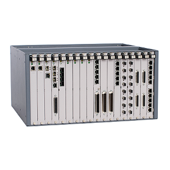
Zhone IMACS 8000 User Manual (788 pages)
Integrated Access Device
Brand:
Zhone
| Category:
Network Router
| Size: 18 MB
Table of Contents
Table of Contents
3
Chapter 1 What's New
33
Product Description
33
CPU Card Support
33
Interface Cards Supported in Release
34
Low Interruption Cards Supported on the IMACS 8000
34
System Cards
34
Card Support
34
Cpu Xcon (Cpu)
34
Low Impact Supported Card List
34
Voice Cards
35
Data Cards
35
Server Cards
36
Alarm Cards
36
CPU Cards
36
Interface Cards
36
Power Cards
36
WAN Cards
37
Shelf Hardware
37
Customer Service and Ordering Information
37
Technical Support
37
Chapter 2 System Installation
39
Introduction
39
User-Set Switches and Jumpers
39
Chassis Installation
39
Unpacking the Chassis and Cards
39
Pre-Installation Tips
39
Installation Checklist
39
Choosing a Location for Your System
40
Rack Installation Tips
41
Wall-Mount Installation Tips
41
Tabletop Installation Tips
42
Installing the Chassis
42
Mounting Bracket Holes
42
Chapter 3 8000 Chassis
43
Power Supplies and Ringing Generators
43
Chassis Mounting Holes
43
Minimum Chassis Clearances
43
System Power (Redundancy)
44
48V Talk Battery Requirements
44
Setting the U.s./European Configuration Jumper
44
JP1 Jumper Settings
44
Installing the System Power Cards
45
Talk Battery Supply Fuses
45
AC Power Supply and DC Power Supply Fuses
45
Installing AC or DC Power Supplies
45
Installing the -48V Converters
46
Ringing Generators
46
Ringing Generators (890620)
46
Installing the 105V Ringing Generator (890620)
47
System Power and Ground Connections
49
Chassis with Power Supplies
49
DC Terminal Block in a DC Environment with One Power Source
50
DC Powered System - Single DC Power Supply in Slot F1 - no Voice Cards
52
Terminals on DC Terminal Block
52
Redundant DC Power Supplies with Redundant Power Feeds - no Voice Cards
53
Redundant DC Power Supplies with Non-Redundant Power Feeds - no Voice Cards
53
Completely Redundant DC Power Supplies and All Feeds
54
Redundant DC Power Supplies with One Non-Redundant Power Feed for All Functions
54
Powering up the System
55
Installing the Other Plug-In Cards
55
Interface Cards
55
CPU Cards
56
WAN Cards
56
Server Cards
56
Watt Load Card
56
Connecting Cables to the Cards
57
IMACS 8000 Chassis Description 3.1 Introduction
59
Chassis
60
Front-Loading 8000-CHASSIS with Rear Power Supply
60
Chassis Rear (8000-CHASSIS)
61
External Power Source for the Power Enhanced Chassis (8000-CHASSIS)
62
Card Slots for the 8000-CHASSIS
63
And European Chassis Configuration
64
Chapter 4 Applications 4.1 Introduction
65
Voice Modules
66
Foreign Exchange Station (FXS) Card (8000-FXS-8P)
66
Foreign Exchange Office (FXO) Card (8000-FXO-8P)
67
E&M Card
68
Voice Channel Bank Application
69
An IAD Used as a Voice Channel Bank
69
TR008 Application
70
IAD Using TR008
70
T1-E1 Conversion Application
71
IAD Using T1/E1 Conversion
71
Data Modules and Applications
72
HSU Cards
72
HSU Application Example
73
OHSU Card
74
SRU Card
74
Point to Multipoint One-Way Video and Audio Using Hsus
74
IAD with SRU Card Application
75
OCU-DP Cards
76
OCU-DP Card Models
76
DSO-DP Card
77
ADPCM Voice Compression Server (8000-ADPCM)
78
PBX to PBX Trunk Application
79
Router Server Card (8000-Router)
79
IAD Using ADPCM for PBX to PBX Application
79
OC3 Point to Point Server (8000-OC3-PT2PT)
80
PWE IP Uplink Server (8000-PWE)
81
Chapter 5 System Configuration and Operation
83
Basic Operations
83
Basic Screen Map and Legend
83
System Initialization
84
Registration
84
First Time Registration Screen
84
First Time Login Screen
85
Welcome to Registration Screen
85
Selecting Chassis Type Screen
86
Testing and Initialization Screen
86
Logging into the System
87
Typical Login Screen
87
User Names, Passwords and Groups
88
CPU Screen - Usernames Option
89
User Access Table
89
User Groups
90
Default User Table
90
User Accesses by Group
90
Default Group Permissions
91
User Name Screen
92
Usrname Screen Actions
93
Adding a User
94
Login Log Sample Display
95
Access Level Permissions
96
Group Permissions Settings
96
System Screens
98
System Main Screen
98
CPU Card Status
98
System Main Screen Actions
98
Power Supplies and Ringing Generators Card Status
99
Voice and Data Card Status
99
Typical Card Status Display
99
Server Card Status
100
WAN Card
100
Card Main Screens
100
Test and Debug Screen
101
Typical Card Main Screen
101
Time Slot Configuration and Cross-Connect Screens
102
Card Configuration
102
Selecting and Configuring Your Cards
102
Recording Your Configuration Settings
103
Reinitializing the System
104
Alarms
105
Cold-Start NVRAM Test Screen
105
Alarm Screens
106
Typical Alarm Screen
106
Alarm Filter Settings
107
Alarm Filters Screen
107
Alarm Filters
107
Alarm Modifiers
109
Alarm Cutoff (ACO)
110
Backplane out of Service (BP_OOS)
110
Alarm Handling
111
Typical Alarm History Screen
111
Time Slot Configuration Screen
112
Deleting an out of Service Card
112
Accepting New Card Settings
112
Cross-Connecting (XCON)
112
System Level Maintenance
112
Test, Debug, Backup & Restore
113
Zipping the System
113
System Test and Debug Screen
113
Zip Screen
113
Debugging the System
114
Registering the System
114
Pre-TFTP Backup and Restore Preparation
114
TFTP Backup for 7.X.y
115
TFTP Restore for 7.X.y
115
ASCII Backup Procedure
116
ASCII Restore Procedure
117
XMODEM 128K and XMODEM 1K Backup
117
XMODEM 128K and XMODEM 1K Restore
118
Taking a Card out of Service
119
CPU Switching
119
Time Slot Assignment
119
Modes of Operation
120
XCON Mode (XCON)
120
Assigning Time Slots
120
Assigning a Time Slot to a User Card Port
120
Assigning Multiple Time Slots to a Port
121
Typical E&M Card Time Slot Assignments
121
Typical 2-Port HSU Card Time Slot Assignments for T1
122
Typical 4-Port HSU Card Time Slot Assignments for E1
123
Cross-Connect Model
124
Circuit Names
124
Display and Change Circuit Names
125
Cross Connect Screen
125
Cross Connect Screen -View All
126
Cross Connect Circuit (Rename)
126
Cross Connect Rename Circuit (Saving)
127
WAN Cross Connect Screen
127
WAN Cross Connect Screen (Rename)
128
Cross Connect Screen (Rename Displayed)
128
Backup and Restore Circuit Name Table
129
NVRAM Backup Screen
129
Snmp
130
DS0 Naming
130
NVRAM Restore Screen
130
E&M Provisioning Screen
131
Name Screen
131
Automatic Time Slot Assignment
132
Automatic Time Slot Assignment Example
132
Typical Card Slot and Type Selection
133
Typical WAN Card Selection
133
Typical System Main Screen with Alarms
134
Typical WAN Time Slot Assignment Screen
135
Cross-Connecting WAN Time Slots
136
Typical CPU Cross-Connect Screen
136
Add a Cross-Connect Circuit Screen
136
Time Slot Cross-Connection Options and Defaults
137
New Circuit Selection and ID Assignment
138
WAN Unit Options
139
Time Slot and Bandwidth Options
140
Test Options
141
Cross-Connect Circuit Type Selection
142
Trunk Conditioning Option Selection
143
Signaling Bit Pattern Selection
144
Voice Options Screen
144
Selecting PCM Conversion
145
Selecting Signaling Conversion
146
Typical Completed Circuits
146
Cross-Connect Actions
147
CPU Cross-Connect Screen Actions
147
Updated WAN Card Screen
148
Delete Cross-Connection Screen
149
Testing Voice Cross-Connects
150
Typical Message on a CPU Cross-Connect Screen
150
Highlighted Circuit on a WAN Cross-Connect Screen
151
Typical Test Screen and ABCD Bit Options
152
WAN Cross-Connect Test Screen Options
152
Voice Test Diagram
153
Using the Broadcast Option
154
Typical Main Cross-Connect Screen
155
Typical All Circuits Screen
156
Typical Add Broadcast Screen
157
Typical "To" Destination Selection
158
Typical Time Slot Selection
159
Typical Complete Broadcast Circuit
159
WAN Link to WAN Link
160
Broadcast Screen Actions
160
Test Access Digroups (TADS)
161
The TADS Screen
161
Monitor Circuit
162
The Add Monitor Circuit Screen
162
Completed Monitor Circuit
163
Monitor Circuit Diagram
164
Split Circuit
165
TADS Screen with Split Circuits
165
Split Circuit Diagram
166
Release
167
TADS Restore Circuit Screen
167
Terminate and Leave Access
168
TLA Circuit State Screen
168
TLA Circuit State Screen Menu of Actions
168
Checking the Time Slot Map
170
Typical Time Slot Screen for T1 Operation
170
Typical Time Slot Screen in E1 Operation
171
Recording the Time Slot Configuration
172
Time Slot Recording Form for T1 Operation
172
Time Slot Recording Form for E1 Operation
173
Redundant Operations
174
Power Supply Redundancy
174
Typical Redundant-Power Supply System Main Screen
175
CPU Card Redundancy
176
Manually Switching to a Redundant CPU
176
Typical System with CPU Switchover Completed
177
WAN Card Redundancy
178
Cross-Connect WAN Card Redundancy Switching
178
Typical Cross-Connect System with WAN Card Redundancy
179
Switching to a Redundant Cross-Connect WAN Card
180
Interface Card (IF) Redundancy
181
Typical Cross-Connect WAN Card Redundancy Switch in Progress
181
ADPCM Card Redundancy
182
Typical System with ADPCM Cards
182
Typical ADPCM Card Main Screen
183
Typical ADPCM Card Redundancy
184
Analog Bridge Card Redundancy
185
Typical System with Dual Analog Bridge Cards
185
Analog Bridge Card Main Screen
186
Changing the Analog Bridge Card to Redundant
186
Analog Bridge Card in Redundant Mode
187
PWE Card Redundancy
188
Typical System with Dual PWE Cards
188
PWE Card Main Screen
189
System Redundancy
190
Alternate Mapping Table (AMT)
190
PWE Card in Redundant Mode
190
Alternative Mapping Table
191
Xcon Screen - Amt Options
191
Remote AMT
192
Alternative Mapping Table Options Screen
192
Remote AMT Main Screen
193
Remote Shelf with Database Restored
194
Active AMT
195
Active AMT Main Screen
196
Alarm Filter Triggers
197
Alarm Trigger Selections
197
Alarm Information
198
Quick Tips
198
Chapter 6 System Testing and Diagnostics
199
Introduction
199
Integral Test Capabilities
199
User Card Diagnostics
200
WAN Diagnostics
200
Voice Diagnostics
201
Data Diagnostics
201
Diagnostics at the 'X' Cross-Connect Option
204
Circuit Diagnostics
204
Benefits of Built-In Diagnostics
206
Built-In Diagnostics Example (Diagnostics 1 - 4)
207
Built-In Diagnostics Example (Diagnostics 4 - 8)
208
Performance Monitoring
209
T1 Line Performance Monitoring
209
DDS Line Performance Monitoring
209
Chapter 7 CPU Card 7.1 Introduction
211
CPU Card Description
211
CPU XCON with Ethernet Port (CPU)
211
Card Jumper/Switch Settings
212
Installing the CPU-7 XCON with Ethernet Port Card
212
Setting up CPU Ethernet Port
213
CPU Card User Screens and Settings
215
CPU Card Main Screen
215
RADIUS Authentication
216
RADIUS Options
216
CPU Card Main Screen Actions
216
User Names, Passwords and Groups
219
Changing Your Passwords
219
Usrname Screen Actions
219
Login Log Sample Display
220
Other CPU Card Settings
221
Printing Alarms Remotely
223
Typical CPU Print Alarm Screen
224
Print Alarm Screen Actions
224
Print Alarm Screen Options and Defaults
225
Typical Alarm Printout
227
TCP/IP Network Management
228
Typical TCP/IP Network Management System
228
Typical TCP/IP Screen
229
TCP/IP Screen Actions
230
TCP/IP Screen Options and Defaults
230
CPU Default IP Port Selection Screen
232
CPU Default IP Unit Selection Screen
233
Syslog
234
SYSLOG Server Level
235
SYSLOG Level
235
SYSLOG Server Test Log Result
236
SYSLOG CPU / Loading Events
236
SYSLOG Alarm Indications
237
SYSLOG Configuration Change Notifications
237
SYSLOG USER ID Tracking
237
Network Statistics Screens
238
Typical Network Statistics Screen
238
SLIP Parameters
239
Network Statistics Screen Actions
239
FDL Parameters
240
IP Parameters
241
Typical Network Statistics Screen
242
ICMP Parameters
243
TCP State Parameters
245
Typical Network Statistics Screen
245
UDP Parameters
248
Typical Network Statistics Screen
248
TELNET Parameters
249
SNMP Parameters
250
IP Packet Routing
251
Typical Routing Diagram
252
Typical IP Routing Screen
253
Routing Screen Actions
253
Settings for Routing Parameters
254
Routing Address Entry Screen
255
Slot/Unit Options Screen
256
IP Static Routing Information Screen
256
Slot/Unit Options
256
Nx64 Screen
257
Nx64 Main Screen
257
Nx64 Screen Actions
257
Nx64 Screen Options and Defaults
258
Network Statistics Screen
260
Nx64 Netstat Screen
260
Nx64 Netstat Screen Actions
260
CPU Host Software Upgrade Procedure
261
Equipment Requirements
261
Laptop Setup
261
Log Upgrade Activity
262
Upgrades
262
Upgrades Preparation
262
Software Download Procedures
263
High-Level Upgrade Overview
263
Detailed Upgrade Procedure
263
Pre-TFTP Binary Upload/Download Preparation
263
TFTP Protocol bin Download
264
CPU Programming Level
265
XMODEM Protocol Binary Download
266
CPU Card Error Messages
268
CPU Card Troubleshooting
268
CPU Card Specifications
269
Chapter 8 Interface Card
271
Introduction
271
Interface Card Descriptions
271
INTF-R Ext Card Description (IF+EXT)
271
Card Jumper/Switch Settings
272
Installing the INTF-R Ext Card
272
External Sync Daughter Card
272
INTF-R Ext Interface Card (IF+EXT)
272
Equipment Grounding Requirements
273
Jumper Arrangements for the T1/E1 External Sync Card
273
Jumper Settings for the T1/E1 External Sync Card
273
INTF-R Modem Card Description (IF+MODEM)
275
Card Jumper/Switch Settings
275
Installing the INTF-R Modem Card
275
INTF-R Modem Interface Card (IF+MODEM)
275
INTF-R Card Description (IF)
276
Card Jumper/Switch Settings
276
Installing the INTF-R Card
276
INTF-R Interface Card (IF)
276
Interface Card User Screens and Settings
277
Interface Card Main Screen
277
Typical Interface Card Main Screen
277
Setting the System Date and Time
278
Interface Card Main Screen Actions
278
SNTP Time Server Enabled
279
Selecting the System Timing Clocks
280
Interface Card Setting Options and Defaults
280
Call Profile Screen
283
Typical Call Profile Screen
283
Call Profile Screen Actions
284
Call Profile Screen Options and Defaults
284
Signaling Conversion Table Screen
288
Remote IMACS Terminal System (RITS)
289
Identification
289
Signaling Conversion Table Screen Actions
289
Network Priorities
290
Intra-Network Communications
290
Typical RITS Configuration
290
Terminal Security
291
AT" Commands Used by RITS
291
Ports Screen
292
Typical Ports Screen (INTF+M)
292
Interface Card Ports and Functionality
294
Using the Node Port
294
Component Layout for the INF-R Modem and INF-R Interface Cards
294
Interface Ports and Functions
294
Node Port ACO Alarm Interface
295
Interface Card Error Messages
296
Interface Card Troubleshooting
296
User Interface Problems
296
Alarm Reporting Problems
297
WAN Transmission Problems
297
Interface Card Specifications
298
Chapter 9 WAN Card
301
Introduction
301
WAN Card Descriptions
301
WAN DUAL Card with CSU Support Description (801070)
301
Card Jumper/Switch Settings
302
WAN Software Level
304
WAN Software Download
305
WAN Software Level
305
WAN Download Screen
307
WAN Download Options
308
TFTP Download in Progress
309
XMODEM Download Screen
310
WAN DUAL Card Description (801060, 801065)
311
Card Jumper/Switch Settings
312
WAN-R Card Description (801460)
312
WAN-R Card Description (801470)
312
Card Jumper/Switch Settings
313
WAN Software Level
313
WAN Module Descriptions
313
DSX/CEPT Module Description (81130)
313
DSX/CEPT Module Jumper Settings
314
DSX/CEPT Module Installation
314
Installing DSX/CEPT Modules
315
DSX/CEPT Module
316
E1 Interface Adapter Panel (11830 or 1184)
317
CSU Module Description (81230)
318
CSU Module Installation
318
CSU Module Jumper/Switch Settings
318
Installing the WAN Cards
318
WAN-Rr Alarms
318
WAN Card User Screens and Settings
320
T1 CSU and DSX Settings
320
WAN Card Main Screen for T1 CSU and DSX
320
T1 CSU and DSX Main Screen Actions
321
T1 CSU and DSX Option Settings and Defaults
322
DS0-To-SLC-96 Time Slot Conversion
324
AIS/ALM Settings
325
Line and Local Loopbacks
326
Line Loopback
326
DS0 Time Slot Loopback
327
Using WAN Groups
329
E1 CEPT Settings
330
WAN Card Main Screen for CEPT
330
WAN Actions
331
E1 Screen Option Settings and Defaults
332
Cross-Connect (XCON)
336
E1 Cross-Connect Screen (Display Only)
336
T1 WAN Cross-Connect Screen (Display Only)
337
Performance Data
338
Typical Performance Data Screen
338
Performance Data Screen Actions
339
Far-End Performance Data
341
Typical Far-End Performance Data Screen
341
Far-End Performance Data Screen Actions
342
Test Screen
344
Typical WAN Card Test Screen
344
Test Screen Actions
344
WAN Card Test Screen Options
344
WAN Card Error Messages
347
WAN Card Troubleshooting
347
WAN Card Specifications
348
Chapter 10 Alarm Cards 10.1 Introduction
353
Alarm Card Descriptions
353
ALR 4+4 Card Description (8000-ALARM-4P)
353
Card Jumper/Switch Settings
354
Installing the Alarm Card
354
Alarm Card User Screens and Settings
355
Alarm Filter Screen Sensor Setting
355
ALR 4+4 Card Main Screens
355
Alarm Filter Screen
355
ALR 4+4 Card Main Screen
356
ALR 4+4 Card Main Screen Actions
356
ALR 4+4 Card Option Settings and Defaults
357
Alarm Card Error Messages
358
Alarm Card Troubleshooting
358
Chapter 11 E&M Card
361
Introduction
361
E&M Card Descriptions
361
E&M 2W*8 Card Description (8000-EM-2W-8P)
361
Card Jumper/Switch Settings
362
Typical E&M Card Switches
362
Typical E&M Card Switch Definitions
363
Typical E&M Card Switch Settings
363
Installing the E&M 2W*8 Card
364
E&M 4W*8 er Card Description (8000-EM-4W-8P)
364
Card Jumper/Switch Settings
364
Installing the E&M 4W*8 er Card
364
E&M Card User Screens and Settings
365
E&M Card Main Screen
365
Typical E&M Card Main Screen
365
Main Screen Option Settings and Defaults
366
Main Screen Actions
366
E&M Card Loopbacks
369
Test Screen
371
Typical E&M Card Test Screen
371
Test Screen Actions
372
Test Screen Option Settings and Defaults
372
Status Information Field Settings
375
Loopback Screen
376
Typical E&M Loopback Screen
376
Loopback Screen of Actions
376
Loopback Screen Option Settings and Defaults
376
E&M Card Error Messages
378
E&M Card Troubleshooting
378
E&M Card Specifications
380
Chapter 12 FXS Card
383
Introduction
383
FXS Card Description
383
FXS 2W*8-6 Card Description (8000-FXS-8P)
383
Card Jumper/Switch Settings
384
FXS 2W*8-6 Card Jumpers Settings
384
Installing the FXS 2W*8-6 Card
385
FXS Card User Screens and Settings
385
FXS Card Main Screen
385
Typical FXS Card Main Screen
385
Main Screen Actions
386
Main Screen Option Settings and Defaults
386
Incoming Calls (Ls-R2E)
389
Outgoing Calls (Ls-R2E)
389
Incoming Calls (R1.5I)
390
Outgoing Calls (R1.5O)
390
FXS Card Loopbacks
392
Test Screen
395
Typical FXS Card Test Screen
395
Test Screen Actions
395
Test Screen Option Settings and Defaults
396
Status Information Field Settings
399
FXS Error Messages
400
FXS Card Troubleshooting
400
FXS Card Specifications
402
Chapter 13 FXO Card
403
Introduction
403
FXO Card Descriptions
403
FXO 2W*8-6 Card Description (8000-FXO-8P)
403
Card Jumper/Switch Settings
404
Installing the FXO 2W*8-6 Card
404
FXO 2W*8-6 Card Jumper Settings
404
FXO Card User Screens and Settings
405
FXO Card Main Screen
405
Typical FXO Card Main Screen
405
Main Screen Actions
406
Main Screen Option Settings and Defaults
406
FXO Card Loopbacks
410
Test Screen
413
Typical FXO Card Test Screen
413
Test Screen Actions
413
Test Screen Option Settings and Defaults
413
Status Information Field Settings
417
FXO Card Error Messages
418
FXO Card Troubleshooting
418
FXO Card Specifications
420
Chapter 14 HSU Card
421
Introduction
421
HSU Card Description
421
Two-Port HSU530/35 Card Description (8000-HSU-2P)
421
Two-Port HSU Card Jumper/Switch Settings
422
Installing the Two-Port HSU 530/35 Card
422
Two-Port HSU 530/35 Card Switches
422
HSU-T V11 Card Description (8000-HSU-2P-V11)
423
HSU-T V11 Card Jumper/Switch Settings
423
Installing the HSU-T V11 Card
423
HSU 35 Card Description (HSU-2P)
423
HSU 35 Card Jumper/Switch Settings
423
Installing the HSU 35 Card
423
Four-Port HSU 530/35 Card Description (8000-HSU-4P)
423
Four-Port HSU Card Jumper/Switch Settings
424
Installing the Four-Port HSU 530/35 Card
425
Four-Port HSU 530/35 Card Switches
425
Personality Module (1251)
426
RS-232-E Personality Module Description (1253)
427
HSU Card Cables
428
HSU to Cable Matrix (to DTE Clock)
428
HSU to Cable Matrix (to DCE Clock)
428
HSU Card User Screens and Settings
429
HSU Card Main Screen
429
Typical HSU Card Main Screen
429
HSU Card Main Screen Actions
430
HSU Card Setting Options and Defaults
430
HSU Card State Status
431
Typical HSU Port Time Slot Assignment Screen
433
Local DTE Loopback
435
Local Network Loopback
436
Remote OCU or DS0 Loopback
437
Remote CSU Loopback
438
Remote DSU Loopback
438
HSU Card Test Screen
440
Typical HSU Card Test Screen
440
Test Screen Actions
440
Test Screen Option Settings and Defaults
441
HSU Dial Screen
445
HSU Dial Screen Actions
446
Dial Screen Option Settings and Defaults
446
Hunt Group
446
HSU Call Profile Screen
448
HSU Card Call Profile Screen
449
HSU Card Call Profile Screen Actions
449
HSU Card Call Profile Screen Option Settings and Defaults
450
Broadcast Screen
453
HSU Broadcast Function
453
HSU Broadcast Screen
454
Broadcast Connection Status Screen
455
Call Profile Broadcast Screen
455
Inverse Multiplexer (IMUX) Screen
456
IMUX Call Screen
456
Call Profile Broadcast Screen Actions
456
IMUX Call Screen Actions
457
IMUX Call Screen Option Settings and Defaults
457
Dialing with High Speed Data Cards
459
Basic HSU Dialing
459
RS366 and V.25Bis HSU Dialing
459
Master Dialing
459
Dialing with RS366 Commands
460
Command Types
460
Escape Character
461
Basic Dialing Changes
461
Values for Service Type Field
461
Example
462
Call Profile Loading
462
Loopback Management
463
Call Profile Changes
463
Call Profile Parameter Numbers and Values
463
Example
464
Master Dialing
464
MUX Call Screen Actions
464
V.25Bis Dialing
465
Field Values for Command Strings
465
The CRN Command
466
The SCT Parameter
466
The BWR Parameter
466
Example
466
The CRS Command
466
Example
467
The DIC Command
467
The CIC Command
467
The INC Indication
467
The VAL Indication
467
The INV Indication
467
Performance Data
467
Typical HSU Performance Data Screen
468
Performance Data Screen Actions
468
HSU Card Error Messages
470
HSU Card Troubleshooting
470
HSU Card Specifications
471
Chapter 15 OHSU-4P Card
475
Introduction
475
OHSU Alarming Capability
475
OHSU Alarm on the Main Screen
475
OHSU Card Description
476
Four-Port OHSU Card Description (8000-OHSU-4P)
476
Installing the Four-Port OHSU Card
477
OHSU Card Cables
477
OHSU Card User Screens and Settings
478
OHSU Card Main Screen
478
Typical OHSU Card Main Screen
478
OHSU Card Main Screen Actions
479
OHSU Card Setting Options and Defaults
479
Typical OHSU Port Time Slot Assignment Screen
480
Local User Loopback
481
Local Network Loopback
482
Alarm Field
482
OHSU Card Specification
483
Chapter 16 LDSRU-10P Card
485
Introduction
485
LD-SRU Card Description
485
LD-SRU*10 Card Description (8000-LDSRU-10P)
486
Card Jumper/Switch Settings
487
Installing the LD-SRU*10 Card
487
Installing the LD-SRU*10 Card
488
LD-SRU Card User Screens and Settings
488
Typical SRU Card Main Screen
488
Main Screen Actions
489
Main Screen Option Settings and Defaults
489
SRU Card State Status
490
SRU Time Slot Integration
492
Local Loopbacks
494
Inband Remote SRU Loopback
495
Inband Remote CSU Loopback
495
Inband Remote DSU Loopback
495
Bit Error Rates for Majority-Vote Error Correction
496
Card Configuration Examples
498
Typical WAN Time Slot Assignments to an SRU Card
499
Test Screen
500
Typical SRU Card Test Screen
500
Test Screen Actions
501
Test Screen Option Settings and Defaults
501
SRU Card Error Messages
505
SRU Card Troubleshooting
505
SRU Card Specifications
507
Chapter 17 OCU-DP Card
509
Introduction
509
OCU-DP Card Descriptions
509
OCU-DP 5 Card Description (8000-OCUDP-5P)
509
Card Jumpers/Switch Settings
509
Installing the OCU-DP 5 Card
510
OCU-DP 10 Card Description (8000-OCUDP-10P)
510
Card Jumpers/Switch Settings
510
Installing the Card
510
OCU-DP Card User Screens and Settings
510
OCU-DP Card Main Screen
510
Typical OCU-DP Card Main Screen
511
Main Screen Actions
512
Main Screen Option Settings and Defaults
512
Data Frames, Rates, and Time Slot Assignments
514
OCU-DP Primary and Secondary Channel Rates
515
OCU Local Loopback (Dte Option)
516
OCU Local Loopback (Net-A Option)
517
OCU Local Loopback (Net-D Option)
517
OCU Remote Loopback (Ds0-N and Ocu-N Options)
518
OCU Remote Loopback (Csu-N Option)
518
OCU Remote Loopback (Csu-U Option)
518
Performance Data Screen
519
Typical Performance Data Screen
520
Performance Data Screen Actions
521
Test Screen
522
Typical OCU-DP Card Test Screen
522
Test Screen Actions
523
Test Screen Option Settings and Defaults
523
OCU-DP Card Error Messages
526
OCU-DP Card Troubleshooting
526
OCU-DP Card Specifications
527
Chapter 18 DS0-DP Card
529
Introduction
529
DS0-DP Card Description
529
DS0-DP 4 Card Description (8000-DS0DP-4P)
529
Card Jumper/Switch Settings
529
Installing the Card
529
DS0-DP Card User Screens and Settings
530
DS0-DP Card Main Screen
530
Typical DS0-DP Card Main Screen
530
Main Screen Actions
531
Main Screen Option Settings and Defaults
531
DS0-DP Card Error Messages
534
DS0-DP Card Troubleshooting
534
DS0-DP Card Specifications
535
Chapter 19 ADPCM Card
537
Introduction
537
ADPCM Card Descriptions
537
ADPCM 64 Card Description (8000-ADPCM)
537
Card Jumper/Switch Settings
538
Installing the ADPCM Card
538
ADPCM Compression Rates
538
ADPCM Card User Screens and Settings
539
ADPCM Card Main Screen
539
Typical ADPCM Card Main Screen
539
ADPCM Card Main Screen Actions
540
ADPCM Card Setting Options and Defaults
540
ADPCM Card Error Messages
543
ADPCM Card Troubleshooting
543
ADPCM Server Card Specifications
544
Chapter 20 Analog Bridging Server Card
545
Introduction
545
Analog Bridging Server Card Description (8000-BRIDGE)
545
Card Jumper/Switch Settings
546
Installing the Analog Bridge Server Card
546
Analog Bridge Server
546
Analog Bridge Server Card User Screens and Settings
547
Analog Bridge Provisioning
547
Analog Bridge Server Card Main Configuration Screen
547
Analog Bridge Server Main Screen
547
Analog Bridge Main Screen Actions
547
Analog Bridge Main Screen Option Settings and Defaults
548
Port Provisioning on the Bridge
550
Bridge Port Screen
550
Analog Bridge Port Screen Actions
550
Analog Bridge Port Screen Option Settings and Defaults
551
Bridge 5 - Three Ports in Use
553
All Ports Screen
554
E&M Card Screen
554
Bridge All Ports Command
555
Bridge 14 Display - Ports on the Bridge
556
All Ports - Delete a Port
557
Analog Bridge Server Card Specifications
558
Chapter 21 IPR*4 Router Card
559
Introduction
559
IPR*4 Router Card Descriptions
559
IPR*4 Router 10/100BT Card Description (8000-ROUTER-PPP-HS)
559
IPR*4 Available Options
560
Card Jumpers/Switch Settings
561
Installing the IPR*4 Cards
561
IPR*4 Card Layout
561
IPR*4 Configuration in a PPP Network
562
IPR*4 Connecting IP Lans
562
IPR*4 Card Connected to IP Lans through a PPP Network
562
IPR*4 Card Configuration Screens and Settings
563
IMACS Main Screen
563
IPR*4 Card Interactions
563
IMACS Management through the IPR*4 Card
564
IPR*4 10/100BT (ROUTER-PPP-HS) Card Main Screen
564
Setting the CPU Management through the IPR*4 Card
564
IPR*4 10/100BT Card Interface Main Screen
565
IPR*4 Provisioning Card Setup
566
IPR*4 10/100BT Card Main Screen Actions
566
IPR*4 Card Download
568
IPR*4 Download Screen
568
Tftp and Xmodem Upgrades
569
Configuration Change - Reprovisioning Needed
570
An In-Process IPR*4 Card Download
570
Checksum Passed, Writing Load to Flash
571
Xpress Upgrade Option
572
Xpress Download of IPR*4 Card
573
Download Confirmation
573
Configuration Change - Reprovisioning Needed
574
Xpress Download in Progress
575
IPR*4 Card Alarm and Upgrade Events
576
IPR*4 Card Troubleshooting
576
Introduction
578
IPR*4 PPP Option
578
IPR*4 Card Connected to IP Lans through a PPP Network
580
IPR*4 Configuration in a PPP Network
580
IPR*4PPP Configuration Screens and Settings
581
IPR*4 10/100BT (ROUTER-PPP-HS) Card Main Screen
581
IPR*4 10/100BT Card Interface Main Screen
581
IPR*4 Provisioning Card Setup
583
IPR*4 INTF NAME Screen
584
INTF Name Screen
584
IPR*4 Ethernet Connectivity Screen
585
IPR*4 Interface Name Screen Action
585
Ethernet Screen for IPR*4 Card
586
IPR*4 10/100BT Ethernet Menu Option Settings and Defaults
586
IPR*4 Ethernet Connectivity Screen - Perf
588
IPR*4 Ethernet Connectivity Screen - ARP
588
IPR*4 Ethernet Performance Screen
588
IPR*4 Port Screen
589
IPR*4 10/100BT ARP Table Screen
589
IPR*4PPP Port Display
590
IPR*4 Port Menu Option Settings and Defaults
590
IPR*4 10/100BT Port Menu Option Settings and Defaults
591
IPR*4 Static Route Screen
593
IPR*4 Static Route Entry
593
IPR*4 10/100BT IP Static Routes Configuration Table Screen Actions
593
IPR*4 Server Card Specifications
595
Chapter 22 MCC Card
597
Introduction
597
ACS-MCC Card Descriptions
597
ACS-MCC Card Description (881360)
597
Jumper/Switch Settings
598
Installing the Card
598
Typical MCC Application
598
ACS-MCC Card User Screens and Settings
599
ACS-MCC Card Main Screen (Ethernet Port Configuration)
599
Typical ACS-MCC Card Main Screen
599
Main Screen Actions
600
Main Screen Option Settings and Defaults
600
C-Port and Numbered Port Configuration (1.1 Version Only)
603
Typical C-Port Screen
603
Typical Numbered Port Screen
604
Port Assignment Screen Actions
604
Port Screen Option Settings and Defaults
605
Network Port Statistics Screen
607
Typical Network Port Data Screen
607
MCC Protocol Stack Data Screen
609
Typical MCC Protocol Stack Data Screen
609
Network Port Data Screen Actions
609
ACS-MCC Card Error Messages
612
ACS-MCC Card Troubleshooting
612
Chapter 23 OC3 Card
615
Introduction
615
OC3 Card Description
615
OC3 Card Description (8000-OC3-PT2PT)
615
Card Jumper/Switch Settings
616
OC3 Point to Point Offering
616
Faceplate Descriptions
617
OC3 Server Card
617
Installing the Card
618
OC3 Card User Screens and Settings
618
OC3 Card Main Screen
618
IMACS Main Screen with OC3 Installed
618
OC3 Setup Screen
619
OC3 Main Card Screen
619
Main Screen Actions
620
Provisioning the Sixteen External T1/E1 Facilities
621
LOS Alarm on External Facility, Manifest Indication of EXT Alarm on P3
621
OC3 STS VT 1.5 Mapping Defined by GR-253-Core
622
OWAN Facility Screen
623
Main Screen Option Settings and Defaults
624
STATE and TRIB Provisioning
625
OC3 Card Error Messages
626
OC3 Card Troubleshooting
626
Chapter 24 PWE Card
627
Introduction
627
PWE Card Description
627
Card Jumper/Switch Settings
628
IMACS PWE Sample Configurations
628
Faceplate Descriptions
629
PWE Server Card
629
Installing the Card
630
PWE Card User Screens and Settings
630
PWE Card Main Screen
630
IMACS Main Screen with PWE Installed
630
PWE Card Initial Setup Parameters
631
PWE Card Main Screen
632
Pseudowire to WAN Associations
632
Main Screen Option Settings
633
PWE Card Setting Options and Defaults
633
Main Screen Actions
636
Creating a Pseudowire Stream for WAN 2-2 (PW4)
637
PWE Port Statistics
638
ARP Screen
639
SFP Read Information
639
PWE Card Error Messages
641
PWE Card Troubleshooting
642
No Communications with the Far End
642
Clock Failing to Lock
643
Excessive Errors in Data Services / Excessive Voice Echo
643
Appendix A System Standards and Specifications
645
Introduction
645
Standards Compatibility
646
Chassis Standards
653
Dimensions
653
Chassis Power
654
Environment
654
Ambient Temperature and Humidity
654
Altitude
654
Airflow
655
Fire Resistance
655
Equipment Handling
655
Packaged Equipment Shock Criteria
655
Unpackaged Equipment Shock Criteria
655
Earthquake, Office Vibration and Transportation Vibration
655
Earthquake
655
Office Vibration
655
Transportation Vibration
655
Mounting
656
Types
656
Clearance
656
Cable/Power Connections
656
System Power Supplies and Converters
657
Power Supply Compatibility
658
External Talk Battery Fuses
659
Card Specifications
660
Pre-Installation Card Setup
661
FCC Requirements
662
UK Requirements
663
Year 2000 Compliance
663
Service Requirements
663
Safety Information and Precautions
664
Disclaimer for Shielded Cables
665
Panel and Cover Removal
665
Power Source
666
Fusing
666
Power Supply Safety Information
666
Grounding
666
A.9.3 Power Source
666
Electrostatic Discharge Prevention
667
Operator Services Requirements
667
Regulatory Compliance Information
667
FCC Part 68 Information
667
CE Marking
668
Declaration of Conformity
668
A.11.2 CE Marking
668
Country-Specific Regulatory Compliance Information
669
Canada
669
Canadian DOC Information
669
Japan
670
Class a ITE Notification
670
Europe
670
European Telecommunication Approvals
670
United Kingdom
670
UK Approval Number
670
A.12.2 Japan
670
UK Compliance Statements
671
A.12.4.2 UK Compliance Statements
671
Germany
672
German Approval Number
672
A.12.5 Germany
672
Appendix B Error Messages
675
Error Messages Introduction
675
Appendix C Pinouts
699
Introduction
699
C.1 Introduction
699
CPU Card
700
CPU Card (CPU
700
CPU External Connector and Pinouts
700
C.2 CPU Card
700
RJ48 Ethernet Jack
701
RJ48 Ethernet Port Jack Pinouts
701
Interface Cards
702
INF-R EXT Card (IF+EXT
702
INF-R External Connector and Pinouts
702
INF-R EXT Card Connectors (IF+EXT
702
C.3 Interface Cards
702
RJ45 (COM2) Jack
703
RJ45 (COM2) Jack Signal Pinouts
703
RJ45 Node Jack
704
RJ45 (NODE) Jack Signal Pinouts
704
RJ45 External Sync Jack
706
RJ45 External (SYNC) Jack Signal Pinouts
706
Management Connector
707
Management Connector Signal Pinouts
707
NET Jack
708
NET Jack Signal Pinouts
709
INF-R MODEM Card (IF+MODEM
710
INF-R MODEM Card External Connector and Pinouts
710
INF-R Modem Card Jacks (IF+MODEM
710
MODEM Jack
711
Modem Specifications
711
RJ45 (NODE) Jack
712
RS232 (TERM) Local Interface Jack
713
RS232 (TERM) Jack Signal Pinouts
713
Management Connector
714
Management Connector Signal Pinouts
714
NET Jack
715
NET Jack Signal Pinouts
716
INF-R Card (if
717
INF Card External Connector and Pinouts
717
INF-R Interface Card Jacks (if
717
RJ45 (NODE) Jack
718
RS232 (TERM) Local Interface Jack
719
RJ45 (NODE) Jack Signal Pinouts
719
RS232 (TERM) Jack Signal Pinouts
719
Management Connector
720
Management Connector Signal Pinouts
720
NET Jack
721
NET Jack Signal Pinouts
722
Alarm Cards
723
ALR 4+4 Card
723
ALR 4+4 Card Jack
723
ALR 4+4 Card Jack Pinouts
723
C.4 Alarm Cards
723
E&M Cards
724
E&M 2W*8 Card Jack
724
E&M 2W*8 Card Jack Pinouts
724
C.5 E&M Cards
724
E&M 4W*8ER Card Jack
725
C.5.2 E&M-4W-8P Card (811960)
725
E&M 4W*8ER Card Jack Pinouts
726
FXS Cards
727
FXS 2W*8-6 Card Jack
727
FXS 2W*8-6 Card Jack Pinouts
727
C.6 FXS Cards
727
FXO Cards
728
FXO-8P Card (813970
728
FXO 2W*8-6 Card External Connector and Pinouts
728
FXO 2W*8-6 Card Jack
728
FXO 2W*8-6 Card Jack Pinouts
728
C.7 FXO Cards
728
HSU Cards
729
C.8 HSU Cards
729
HSU 35 Card (HSU-2P
730
HSU 35 Card External Connectors and Pinouts
730
HSU 35 Card Jack Pin Orientation
730
HSU 35 Card Jack Signal Pinouts
730
Four-Port HSU 530/35 Card (HSU-4P
731
Four-Port HSU 530/35 Jack Pinouts
732
HSU Card Cables
733
HSU to Cable Matrix (to DTE Clock
733
HSU to Cable Matrix (to DCE Clock
733
HSU to Cable Matrix (DCE Provides Clock
734
OHSU Card
735
Fiber ST Connectors (OHSU-4P / 823875
735
OHSU Card ST Connector Designation
735
C.9 OHSU Card
735
SRU Cards
736
C.10 SRU Cards
736
SRU-LD*10 Card (822560 / LDSRU-10P
737
SRU-LD*10 Card External Connector and Pinouts
737
SRU-LD*10 Card Jacks (822560 / LDSRU-10P
737
SRU-LD*10 Card Jack Pinouts
738
OCU-DP Cards
739
OCU-DP 5 Card (OCUDP-5P
739
OCU-DP 5 Card External Connectors and Pinouts
739
C.11 OCU-DP Cards
739
OCU-DP 5 Jack Signals Pinouts
740
OCU-DP 10 Card (OCUDP-10P
741
OCU-DP 10 Card External Connectors and Pinouts
741
OCU-DP 10 Card Jacks (OCUDP-10P
741
OCU-DP 10 Jack Signals Pinouts
742
DS0-DP Cards
743
DS0-DP 4 Card (DS0DP-10P
743
DS0-DP 4 Card External Connector and Pinouts
743
DS0-DP 4 Card Jacks (DS0DP-10P
743
C.12 DS0-DP Cards
743
DS0-DP 4 Card Jack Pinouts
744
Server Cards
745
MCC Server Card (881360
745
ACS-MCC External Connectors and Pinouts
745
ACS-MCC Card Ethernet Port Jack
745
ACS-MCC Card Ethernet Jack Pinouts
745
C.13 Server Cards
745
IPR*4 10/100 BT Card (ROUTER-PPP-HS
746
IPR*4 10/100 BT Card External Connectors and Pinouts
746
IPR*4 10/100 BT Card Ethernet Port Jack
746
IPR*4 10/100 BT Card Ethernet Jack Pinouts
746
OC3 TDM Mapper Card (882570
747
OC3 TDM Mapper Card External Connectors and Pinouts
747
OC3 TDM Mapper Faceplate
747
C.13.3 OC3 TDM Mapper Card (882570)
747
OC3 Faceplate
749
PWE Mapper Card (883570
750
PWE IP Uplink Mapper Card External Connectors and Pinouts
750
PWE IP Uplink Card Faceplate
750
C.13.4 PWE Mapper Card (883570)
750
RJ45 Gigabit Ethernet Port
751
RJ45 Pinout
751
Appendix D Node Management Provisioning Examples
753
Introduction
753
Remote Management of IMACS Using the E1 SA4 Bit
753
Sample Remote Management Need - E1
753
D.1 Introduction
753
Setting up the Local IMACS to Provide Remote Access
754
Setting up the Remote IMACS to Provide Remote Access
755
Remote Management of an IMACS Using DS0 Daisy-Chaining
756
Setting up the Local IMACS for Ethernet Hosting
756
Sample Remote Management Need - T1 or E1
756
Setting up the Transport IMACS for DS0 Daisy-Chaining
757
Setting up the Termination IMACS for DS0 Daisy-Chaining
758
Appendix E Glossary
759
Index
779
Advertisement
Advertisement
Related Products
Zhone IMACS 800
Zhone IMACS/800
Zhone IMA CS-200 System
Zhone IMACS-200-48VDC-OHSU
Zhone IMACS-200-48VDC-OW
Zhone IMACS-200-RDNT-48VDC-OW
Zhone IMACS-200-AC-OHSU
Zhone IMACS-200-RDNT-AC-OW
Zhone IMACS-200-AC-OHSU-OW
Zhone IMACS-200-RDNT-125VDC-OHSU-OW
Zhone Categories
Network Router
Modem
Network Hardware
Wireless Access Point
Wireless Router
More Zhone Manuals
Login
Sign In
OR
Sign in with Facebook
Sign in with Google
Upload manual
Upload from disk
Upload from URL