Sign In
Upload
Manuals
Brands
Agilent Technologies Manuals
Measuring Instruments
E5070B
Agilent Technologies E5070B Manuals
Manuals and User Guides for Agilent Technologies E5070B. We have
1
Agilent Technologies E5070B manual available for free PDF download: User Manual
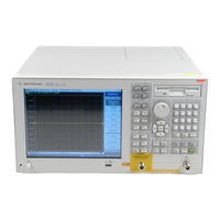
Agilent Technologies E5070B User Manual (769 pages)
RF Network Analyzers
Brand:
Agilent Technologies
| Category:
Measuring Instruments
| Size: 32.37 MB
Table of Contents
Safety Symbols
10
Table of Contents
15
Precautions
31
Software Installed
32
Before Contacting Us
33
Overview of Functions
35
Front Panel: Names and Functions of Parts
36
Standby Switch
37
LCD Screen
37
ACTIVE CH/TRACE Block
38
RESPONSE Block
39
STIMULUS Block
40
Floppy Disk Drive
40
NAVIGATION Block
41
ENTRY Block
42
INSTR STATE Block
43
MKR/ANALYSIS Block
44
Test Port
44
Front USB Port
45
Ground Terminal
45
Screen Area: Names and Functions of Parts
46
Menu Bar
46
Data Entry Bar
46
Softkey Menu Bar
48
Instrument Status Bar
50
Channel Window
52
Rear Panel: Names and Functions of Parts
60
Handler I/O Port
61
Ethernet Port
61
External Monitor Output Terminal (Video)
61
GPIB Connector
61
External Trigger Input Connector (Ext Trig)
61
Fan
61
Line Switch (Always ON)
61
Power Cable Receptacle (to LINE)
62
High Stability Frequency Reference Output Connector (Ref Oven, Option 1E5 Only)
62
External Reference Signal Input Connector (Ref In)
62
Internal Reference Signal Output Connector (Ref Out)
63
Serial Number Plate
63
Certificate of Authenticity Label
63
Rear USB Port
63
Reserved Port (Reserved)
63
Printer Parallel Port
63
Mini-DIN Keyboard Port
63
Mini-DIN Mouse Port
64
USB (USBTMC) Interface Port
64
Setting Measurement Conditions
65
Initializing Parameters
66
Setting Channels and Traces
67
Setting Upper Limits of Number of Channels/Traces
67
Setting Channel Display (Layout of Channel Windows)
68
Setting Trace Display
70
Active Channel
72
Active Trace
72
Parameter Setting for each Setup Item (Analyzer, Channel, Trace)
73
Setting the System Z0
75
Setting Stimulus Conditions
76
Setting Sweep Type
76
Setting the Sweep Range
76
Turning Stimulus Signal Output On/Off
79
Setting Fixed Frequency at Power Sweep
79
Setting Power Level with Auto Power Range Set Function
80
Setting Power Range Manually
83
Setting the Number of Points
84
Setting the Sweep Time
84
Selecting Measurement Parameters
86
Definition of S-Parameters
86
Setting up S-Parameters
86
Selecting a Data Format
87
Rectangular Display Formats
87
Polar Format
88
Smith Chart Format
89
Selecting a Data Format
90
Setting the Scales
91
Auto Scale
91
Manual Scale Adjustment on a Rectangular Display Format
91
Manual Scale Adjustment on the Smith Chart/Polar Format
93
Setting the Value of a Reference Line Using the Marker
93
Setting Window Displays
94
Maximizing the Specified Window/Trace Display
94
Turning off the Display of Graticule Labels
94
Hiding Frequency Information
95
Labeling a Window
95
Setting Display Colors
97
Calibration
99
Measurement Errors and Their Characteristics
100
Drift Errors
100
Random Errors
100
Systematic Errors
101
Calibration Types and Characteristics
105
Checking Calibration Status
108
Execution Status of Error Correction for each Channel
108
Execution Status of Error Correction for each Trace
108
Acquisition Status of Calibration Coefficient for each Channel
109
Selecting Calibration Kit
111
Setting the Trigger Source for Calibration
112
OPEN/SHORT Response Calibration (Reflection Test)
113
Procedure
113
THRU Response Calibration (Transmission Test)
116
Procedure
116
1-Port Calibration (Reflection Test)
119
Procedure
120
Enhanced Response Calibration
121
Procedure
122
Full 2-Port Calibration
124
Procedure
125
Full 3-Port Calibration
127
Procedure
128
Full 4-Port Calibration
130
Procedure
131
Ecal (Electronic Calibration)
133
1-Port Calibration Using a 2-Port Ecal Module
133
Full 2-Port Calibration Using the 2-Port Ecal Module
134
Unknown Thru Calibration
136
Turning off Ecal Auto-Detect Function
137
Full 3-Port and Full 4-Port Calibration Using 2-Port Ecal
138
Operational Procedure
138
Calibration Using 4-Port Ecal
141
Operational Procedure
141
2-Port TRL Calibration
143
Operational Procedure
144
3-Port TRL Calibration
146
Operational Procedure
147
4-Port TRL Calibration
150
Operational Procedure
151
Simplified Calibration
154
Simplified Full 3/4-Port Calibration
154
Simplified 3/4-Port TRL Calibration
155
Partial Overwrite
157
Procedure
157
Improving Accuracy of Measurement Using Partial Overwrite (Thru Calibration) Along with Ecal
158
Unknown Thru Calibration
159
Procedure
159
Calibration between Ports of Different Connector Types
161
Operating Procedure
162
Adapter Characterization
166
Concept
167
How to Execute Adapter Characterization
168
Execution Procedure of Characterization for Test Fixture Using Probe
171
Adapter Removal-Insertion
173
About Adapter Removal
173
About Adapter Insertion
175
Procedure for Adapter Removal / Insertion
176
User-Characterized Ecal
177
Precautions to Take in Using VBA Macros
177
Storing User Characteristics to the Ecal Module
178
Backup and Recovery of Ecal Module's Built-In Flash Memory
182
Executing User-Characterized Ecal
183
Confidence Check on Calibration Coefficients Using Ecal
185
Operational Procedure
185
Changing the Calibration Kit Definition
187
Definitions of Terms
188
Defining Parameters for Standards
189
Redefining a Calibration Kit
191
Example of Defining the TRL Calibration Kit
194
Setting Options for TRL Calibration
196
Setting a Media Type for the Calibration Kit
197
Saving and Loading Definition File of Calibration Kit
198
Default Settings of Pre-Defined Calibration Kits
199
Specifying Different Standard for each Frequency
208
Defining Different Standard for each Frequency Band
208
Defining Standard for each Subclass
209
Disabling Standard Defined for a Subclass
210
Notes on How Frequency Ranges Are Dealt When Using Subclasses
211
Power Calibration
214
Turning on or off Power Level Error Correction
214
Preparing Power Meter and Sensor
215
Selecting Target Port of Error Correction
221
Setting Loss Compensation
221
Setting a Tolerance for Power Calibration
224
Measuring Calibration Data
224
Receiver Calibration
226
Turning ON/OFF Receiver Error Correction
226
Selecting Target Port for Error Correction
227
Measuring the Calibration Data
227
Vector-Mixer Calibration
229
Overview of Vector-Mixer Calibration
229
Measured Mixer
230
Calibration Mixer (with if Filter)
230
Characterizing Calibration Mixer (with if Filter)
230
Characterizing Procedure for Calibration Mixer (with if Filter)
231
How to Execute Characterization of Calibration Mixer
232
Characterizing Calibration Mixer (with if Filter) for Balance Mixer Measurement
236
How to Execute Characterization
236
Scalar-Mixer Calibration
239
Confirming Calibration Status
240
Operational Procedure (When Using Mechanical Calibration Kit)
241
Operational Procedure (When Using Ecal Module)
244
Making Measurements
247
Setting up the Trigger and Making Measurements
248
Sweep Order in each Channel
248
Trigger Source
249
Trigger Modes
249
Setting up the Trigger and Making Measurements
249
Setting the Point Trigger
251
Procedure to Set the Point Trigger
251
Setting the Low-Latency External Trigger Mode
252
Procedure to Set the Low-Latency External Trigger
252
External Trigger Delay Time and Point Trigger Interval
253
Setting the Averaging Trigger Function
255
Using the Averaging Trigger Function
255
Executing a Trigger Only for Active Channel
256
Procedure to Set the Range
256
Data Analysis
257
Analyzing Data on the Trace Using the Marker
258
About Marker Functions
258
Reading Values on the Trace
259
Reading the Relative Value from the Reference Point on the Trace
262
Reading Only the Actual Measurement Point/Reading the Value Interpolated between Measurement Points
263
Setting up Markers for each Trace/Setting up Markers for Coupled Operations between Traces
264
Listing All Marker Values in All Channels Displayed
265
Specifying the Display Position of Marker Values
266
Aligning Maker Value Displays
267
Displaying All Marker Values for Displayed Traces
268
Searching for Positions that Match Specified Criteria
269
Setting Search Range
269
Automatically Executing a Search each Time a Sweep Is Done (Search Tracking)
270
Searching for the Maximum and Minimum Measured Values
271
Searching for the Target Value (Target Search)
272
Searching for the Peak
274
Determining the Bandwidth of the Trace (Bandwidth Search)
276
Executing a Bandwidth Search
276
Determining the Mean, Standard Deviation, and P-P of the Trace
278
Displaying Statistics Data
278
Comparing Traces/Performing Data Math
279
Performing Data Math Operations
279
Performing Parameter Conversion of Measurement Results
281
Operational Procedure
281
Using the Equation Editor
283
Procedure to Start the Equation Editor
283
Procedure to Use the Equation Editor
283
Enabling/Disabling the Equation Editor
285
Entering the Equation Label
285
Fixture Simulator
287
Overview of Fixture Simulator
288
Functions for Single-Ended (Unbalanced) Port
289
Balance-Unbalance Conversion (Option 313, 314, 413, or 414)
290
Functions for Balanced Port (Option 313, 314, 413, or 414)
290
Extending the Calibration Plane Using Network De-Embedding
291
Using the Network De-Embedding Function
291
Converting the Port Impedance of the Measurement Result
292
Converting the Port Impedance
292
Determining Characteristics after Adding a Matching Circuit
293
Using the Matching Circuit Function
293
Obtaining Characteristics after Embedding/De-Embedding 4-Port Network
296
Operational Procedure
297
Evaluating Balanced Devices (Balance-Unbalance Conversion Function)
299
Measurement Parameters of Balanced Devices
301
Steps for Balance-Unbalance Conversion
304
Steps for Measurement Parameter Setups
305
Checking Device Type and Port Assignment
305
Converting Reference Impedance of Balanced Port
306
Converting Port Reference Impedance in Differential Mode
307
Converting Port Reference Impedance in Common Mode
307
Determining the Characteristics that Result from Adding a Matching Circuit to a Differential Port
309
Example of Using Fixture Simulator
312
Measurement Circuit Example for a DUT with Balanced Port
312
Evaluation Using an Actual Test Fixture
312
Problems in Measurement with an Actual Test Fixture
313
DUT Evaluation Using the E5070B/E5071B's Fixture Simulator
314
Advantages of Balanced DUT Evaluation Using Fixture Simulator
316
Frequency-Offset Measurement (Option 008)
317
Overview
318
Overview of Frequency-Offset Measurement
318
Measurement of Mixers
319
Measurement Flow
319
Setting Frequency-Offset
319
Setting External Signal Source
322
Avoid Spurious Function
326
Changing Frequency Data
327
Implementing Mixer Calibration
329
Conversion Loss Measurement
329
Measurement of Harmonic Distortion
332
Measurement Flow
332
Setting Frequency-Offset Function
332
Implementing Receiver Calibration
333
Setting Absolute Measurement Parameters
333
Harmonic Distortion Measurement
334
Analysis in Time Domain (Option 010)
337
Overview
338
Overview of Time Domain Measurement
338
Comparison to Time Domain Reflectometry (TDR) Measurement
338
Time Domain Function of E5070B/E5071B
339
Transformation to Time Domain
340
Measurement Flow
340
Selecting a Type
341
Setting the Window
343
Calculating Necessary Measurement Conditions
344
Setting the Frequency Range and the Number of Points
348
Setting Display Range
349
Enabling Transformation Function
349
Deleting Unnecessary Data in Time Domain (Gating)
351
Measurement Flow
351
Setting Gate Type
351
Setting Gate Shape
352
Setting Gate Range
353
Enabling Gating Function
354
Characteristics of Response in Time Domain
355
Masking
355
Identifying Mismatch Type
356
Data Output
357
Saving and Recalling Instrument State
358
Compatibility of Files Related to Saving and Recalling
358
Save Procedure
360
Recall Procedure
363
Recall Procedure Using "Recall by File Name" Feature
364
Priority of Recalling the Configuration File at Startup
364
Saving/Recalling Instrument State for each Channel Into/From Memory
365
Operational Procedure
365
Saving Trace Data to a File
366
Saving Data as a CSV File
366
Saving Data in Touchstone Format
367
Saving the Screen Image to a File
372
Organizing Files and Folders
373
To Open Windows Explorer
373
To Copy a File or Folder
373
To Move a File or Folder
374
To Delete a File or Folder
374
To Rename a File or Folder
374
To Format a Floppy Disk
374
Printing Displayed Screen
375
Supported Printers
375
Printed/Saved Images
376
Print Procedure
376
Limit Test
379
Limit Test
380
Concept of Limit Test
380
Displaying Judgment Result of Limit Test
381
Defining the Limit Line
382
Turning the Limit Test ON/OFF
386
Limit Line Offset
387
Initializing the Limit Table
388
Ripple Test
389
Concept of Ripple Test
389
Displaying Ripple Test Results
390
Configuring Ripple Limit
391
Turning On/Off Ripple Test and Displaying Results
394
Initializing the Limit Table
395
Bandwidth Test
396
Displaying Bandwidth Test Results
397
Set up Bandwidth Test
398
Turning On/Off Bandwidth Test and Displaying Results
398
Optimizing Measurements
399
Expanding the Dynamic Range
400
Lowering the Receiver Noise Floor
400
Reducing Trace Noise
402
Turning on Smoothing
402
Improving Phase Measurement Accuracy
404
Electrical Delay
404
Phase Offset
406
Specifying the Velocity Factor
406
Setting Port Extensions and Loss Values
407
Setting Port Extensions
407
Setting Loss Values
408
Enabling Port Extensions and Loss Values
409
Using the Auto Port Extension Function
410
Reducing Measurement Error in High Temperature Environments
415
Procedure
415
Improving Measurement Throughput
416
Using Fast Sweep Modes
416
Turning off the Updating of Information Displayed on the LCD Screen
420
Turning off System Error Correction
420
Performing a Segment-By-Segment Sweep (Segment Sweep)
421
Concept of Segment Sweep
421
Conditions for Setting up a Segment Sweep
422
Items that Can be Set for each Segment
422
Sweep Delay Time and Sweep Time in a Segment Sweep
423
Frequency Base Display and Order Base Display
423
Procedure
425
Setting and Using the Control and Management Functions
431
Setting the GPIB
432
Setting Talker/Listener GPIB Address of E5070B/E5071B
432
Setting System Controller (USB/GPIB Interface)
432
Setting the Internal Clock
435
Setting the Date and Time
435
Setting the Date/Time Display ON/OFF
436
Setting the Mouse
437
Setup Step
437
Configuring the Network
440
Enabling/Disabling Network
440
Setting IP Address
441
Specifying Computer Name
443
Remote Control Using HTTP
445
Required Modification of Settings
445
How to Start VNC Server Configuration
445
Accessing Hard Disk of E5070B/E5071B from External PC
446
Enabling the Access Form the External PC
446
Accessing Hard Disk of E5070B/E5071B from External PC
448
Disabling USB Mass Storage Device
449
Steps for Setting Modification
449
Locking the Front Keys, Keyboard, And/Or Mouse (Touch Screen)
450
Locking the Front Keys, Keyboard, And/Or Mouse
450
Setting the Beeper (Built-In Speaker)
451
Setting the Operation Complete Beeper
451
Setting the Warning Beeper
451
Turning off the LCD Screen Backlight
452
Checking the Product Information
453
Checking the Serial Number
453
Checking Other Product Information
453
Setting the Preset Function
455
Showing/Hiding the Confirmation Buttons When Presetting
455
Setting the User Preset Function
455
Saving a User-Preset Instrument State
456
System Recovery
457
Types of System Recoveries
457
Notes on Executing System Recovery
457
Procedure to Execute the Factory Function (1)
458
Procedure to Create the User Backup Image (1)
461
Procedure to Execute the User Recovery Function (1)
464
Procedure to Execute the Factory Recovery Function (2)
467
Procedure to Create the User Backup Image (2)
470
Procedure to Execute the User Recovery Function (2)
473
Calibration of the Touch Screen
476
Initial Source Port Control Function
477
Controlling E5091A
479
Connecting E5070B/E5071B and E5091A
480
Required Devices
480
Powering on
481
Setting the E5091A
482
Selecting ID for E5091A
482
Selecting the E5091A Model
483
Assigning Test Ports
483
Displaying the E5091A Properties
485
Setting Control Line
486
Enabling Control of E5091A
487
Calibration
488
Performing Measurement
489
Trigger State and Switching the Setting of the E5091A
489
Operation
489
Connecting Two E5091As
490
Measurement Examples
491
Measuring the SAW Bandpass Filter Using the Segment Sweep
492
Evaluation Steps
492
Determine the Segment Sweep Conditions
493
?1. Determine the Segment Sweep the Segment Sweep Conditions Are Determined According to the
494
?2. Create a Segment Sweep Table” the Segment Sweep Conditions Are Entered in the E5070B/E5071B.
494
Conditions” on Page 487 Characteristics of the DUT.
494
Create a Segment Sweep Table
494
Select the Segment Sweep as the Sweep Type
496
Execute the Calibration
496
Connect the DUT
497
Execute the Measurement
497
Define the Setup for Display
497
?4. Execute the Calibration” on a 2-Port Ecal Is Performed between the Test Ports Connecting the
496
Sweep Type” on Page 490
496
?3. Select the Segment Sweep as the the Segment Sweep Is Selected as the Sweep Type.
496
?7. Define the Setup for Display” on the Choice Is Made between Frequency Base and Order Base as the
497
?6. Execute the Measurement” on a Trigger Is Applied to Perform the Measurement.
497
?5. Connect the DUT” on Page 491 the DUT Is Connected.
497
Evaluating a Duplexer
499
Evaluation Steps
499
Determine the Segment Sweep Conditions
499
Create a Segment Sweep Table
500
Select the Segment Sweep as the Sweep Type
501
Execute the Calibration
501
Connect the DUT
503
Define the Setup for Display
504
Execute the Measurement
504
Define the Setup for the Segment Display and Scale
504
Analyze the Parameters
505
Define the Setup for a Limit Table
507
Execute the Limit Test
508
Measuring the Deviation from a Linear Phase
511
Evaluation Steps
511
Connect the DUT
511
Define the Measurement Conditions
512
Execute the Calibration
512
Connect the DUT and Execute the Auto Scale
512
Specify the Electrical Delay
513
Measure the Deviation from a Linear Phase
514
Measuring an Unbalanced and Balanced Bandpass Filter
515
Evaluation Steps
515
Connecting the DUT
516
Setting the Measurement Conditions
517
Performing Calibration
518
Setting a Balance Conversion Topology
519
Selecting Measurement Parameters
519
Extending the Calibration Plane (Removing the Cause of Error)
521
Setting the Port Reference Impedances
521
Adding a Matching Circuit
523
Measuring Parameters with Cable
524
Overview of Evaluation Procedure
524
Setting the Measurement Conditions
524
Executing Calibration
524
Connecting the DUT
525
Auto Scale
525
Setting the Time Domain Function
526
Evaluating Transmission Characteristics of a Front End Module
527
Overview of Evaluation Procedure
527
Determining Measurement Conditions
528
Setting Channel Window Allocation
528
Setting the Test Ports
528
Setting Control Line
529
Setting Sweep Conditions
529
Setting Balance Conversion Topology
529
Selecting Measurement Parameter
530
Executing Calibration
530
Connecting DUT
532
Executing Measurement
533
Executing Power Calibration
535
Overview of Execution Procedure
535
Connecting Power Meter
535
Setting Address of Power Meter
536
Setting Stimulus Condition
536
Executing Zero Adjustment and Calibration of Power Sensor
536
Setting Calibration Data Measurement Conditions
536
Connecting Power Sensor
537
Measuring Calibration Data
537
Specifications and Supplemental Information
539
Definitions
540
Corrected System Performance
541
Uncorrected System Performance
546
Test Port Output (Source)
547
Test Port Input
549
General Information
553
Measurement Throughput Summary
561
Measurement Capabilities
564
Source Control
565
Trace Functions
565
Data Accuracy Enhancement
566
Storage
567
System Capabilities
567
Automation
568
Measurement Accessories
569
Test Port Cables
570
N6314A 50 Ω N Type RF Cable (300 Khz ~ 9 Ghz)
570
N6315A 50 Ω N Type RF Cable (300 Khz ~ 9 Ghz)
570
Calibration Kits
571
For Devices with N Type Connectors
571
For Devices with 3.5 MM (SMA) Connectors
574
For Devices with 7 MM Connectors
577
For Devices with 7-16 Connectors
578
Adaptors
579
11853A 50 Ω N Type Accessory Kit
579
11878A N Type to 3.5 MM Adaptor Kit
579
11854A 50 Ω BNC Accessory Kit
579
11852B Minimum-Loss Pad
579
System Accessories
580
System Racks and Cases
580
GP-IB Cables
580
82357A USB/GPIB Interface
580
Information on Maintenance
581
Backing up the Data
582
Making Backup Files
582
Removing/Mounting Removable Hard Disk
583
Removing Removable Hard Disk
583
Mounting Removable Hard Disk
583
Writing System Correction Data from Backup Memory to Removable Hard Disk
585
Cleaning this Instrument
586
Cleaning an LCD
586
Maintenance of Test Ports and Other Connectors/Ports
586
Cleaning a Display Other than an LCD
586
Replacement of Parts with Limited Service Life
587
Cautions Applicable to Requesting Repair, Replacement, Regular Calibration, Etc
588
Backing up Data in the Hard Disk
588
Devices to be Sent Back for Repair or Regular Calibration
588
Recommended Calibration Period
588
Manual Changes
589
Manual Changes
590
Change 14
590
Change 13
591
Change 12
591
Change11
601
Change 10
605
Change 9
605
Change 8
606
Change 7
607
Change 6
607
Change 5
608
Change 4
608
Change 3
611
Change 2
611
Change 1
611
Troubleshooting
613
Troubleshooting
614
Troubleshooting During Startup
614
Troubleshooting During Operation
615
Troubleshooting for External Devices
618
Error Messages
619
Warning Message
632
List of Default Values
635
List of Default Values, Save/Recall Settings, and Backup Settings
636
Softkey Functions
651
E5070B/E5071B Menu (Top Menu)
652
Analysis Menu
653
Average Menu
668
Calibration Menu
669
Display Menu
694
Format Menu
698
Macro Setup Menu
699
Marker Menu
701
Marker Function Menu
703
Marker Search Menu
704
Measurement Menu
707
Measurement Menu (Balance Measurement, SE-Bal)
709
Measurement Menu (Balanced Measurement, Bal-Bal)
710
Measurement Menu (Balanced Measurement, SE-SE-Bal)
712
Preset Menu
714
Save/Recall Menu
715
Scale Menu
719
Stimulus Menu
720
Sweep Setup Menu
721
System Menu
724
Trigger Menu
731
General Principles of Operation
733
System Description
734
Synthesized Source
734
Source Switcher
735
Signal Separator
735
Receiver
735
Data Processing
736
Adc
736
Digital Filter
736
IF Range Correction
737
Ratio Calculation
737
Port Characteristics Correction
737
Sweep Averaging
737
Raw Data Array
737
Error Correction/Calibration Coefficient Data Array
737
Port Extension
737
Fixture Simulator
737
Corrected Data Array
738
Corrected Memory Array
738
Equation Editor
738
Data Math
738
Electrical Delay/Phase Offset
738
Data Format/Group Delay
738
Smoothing
738
Formatted Data Array/Formatted Memory Array
738
Offset/Scale
738
Display
739
Replacing the 8753ES with the E5070B/E5071B
741
Important Functional Differences
742
Channel and Trace Concepts
742
Measurement Parameters
742
Test Port Output Ranges
742
Sweep Function
743
Calibration
744
Trigger System
745
Data Flow
746
Reading/Writing Data
747
Screen Display and Marker Functions
748
Math Operation Functions on Traces
748
Device Test Functions
748
Analytical Functions
749
Save/Recall
750
Test Sequence Program
750
Outputting to a Printer/Plotter
750
GPIB Interface
750
LAN Interface
750
Other Functions
750
Comparing Functions
751
Advertisement
Advertisement
Related Products
Agilent Technologies E5070B ENA Series
Agilent Technologies E5071B ENA Series
Agilent Technologies E5072A
Agilent Technologies E5071B
Agilent Technologies E5070
Agilent Technologies E5071A
Agilent Technologies E5071C ENA Series
Agilent Technologies E5070A ENA Series
Agilent Technologies E5071A ENA Series
Agilent Technologies E5072A ENA Series
Agilent Technologies Categories
Measuring Instruments
Laboratory Equipment
Test Equipment
Water Pump
Power Supply
More Agilent Technologies Manuals
Login
Sign In
OR
Sign in with Facebook
Sign in with Google
Upload manual
Upload from disk
Upload from URL