Table of Contents
Advertisement
Advertisement
Table of Contents

Subscribe to Our Youtube Channel
Related Manuals for INVT Goodrive300-21 Series


Summary of Contents for INVT Goodrive300-21 Series
- Page 1 series Dual-inverter Goodrive300-21 Integrated Machine for Air Compressor...
- Page 2 Preface Preface Goodrive300-21 series dual inverter integrated machine for air compressor (hereafter referred to as Goodrive300-21 air compressor integrated machine) is especially developed for synchronous / asynchronous twin screw air compressor. It can be used in combination with VT6070E series touch screen to drive and control the twin screw air compressor.
-
Page 3: Table Of Contents
Goodrive300-21 integrated machine for air compressor Contents Contents Preface ............................i Content ............................ii 1. Product overview ........................1 1.1. Product specification ......................1 1.2. Product nameplate ......................2 1.3. Type designation ........................ 2 1.4. Rated value ........................3 2. Installation guidance ......................... 4 2.1. -
Page 4: Product Overview
Goodrive300-21 integrated machine for air compressor Product overview 1. Product overview Goodrive300-21 air compressor integrated machine is capable of providing dual inverter output of master and fan to the air compressor and offering +24V power to the touch screen. It supports control of solenoid valve and receiving of temperature and pressure signal. -
Page 5: Product Nameplate
AC 3PH 0V-Uinput 3A 0Hz-50Hz(fan) S/N: Made in China Shenzhen INVT Electric Co., Ltd. Fig 1.1 Product nameplate Note: This is just an example of Goodrive300-21 nameplate, in which the CE/TUV/IP20 part will be marked according to actual certification conditions. -
Page 6: Rated Value
Goodrive300-21 integrated machine for air compressor Product overview Field Symbol Instruction Detailed description Abbreviation of Abbreviation of Goodrive300-21: GD300-21 series dual inverter ① product series product series integrated machine for air compressor ② Rated power Power class 022: 22kW ③ Load type Load type G: Constant torque load... -
Page 7: Installation Guidance
Goodrive300-21 integrated machine for air compressor Installation guidance 2. Installation guidance 2.1. Wiring and terminal instruction of main circuit 2.1.1. Wiring diagram of main circuit Master Goodrive300-21 Fig 2.1 Wiring diagram of main circuit 2.1.2. Terminal diagram of main circuit The terminal layout of 15–22kW, 30kW–37kW and 45–90kW main circuit slightly differs from each other. -
Page 8: Control Circuit Connection And Terminal Instruction
Goodrive300-21 integrated machine for air compressor Installation guidance Fig 2.3 Terminal layout of 45–90kW Table 2.1 Terminal instruction Terminal symbol Terminal function 1. Used for voltage sampling connection of optional power detection UA, UB, UC components. 2. Used for input connection of optional contactor components. R, S, T 3PH AC input terminal, connected to the grid U1, V1, W1... - Page 9 Goodrive300-21 integrated machine for air compressor Installation guidance 2.2. Control circuit connection and terminal instruction 2.2.1. Control circuit layout diagram 34PIN CN17 26PIN Goodrive300-21 control CN15 board +24V +24V 485+ CN14-5 485- CGND CN10 CN11 CN12 CN13 CN14 Fig 2.4 Control circuit layout diagram Table 2.2 Terminal instruction Terminal Name...
- Page 10 Goodrive300-21 integrated machine for air compressor Installation guidance Terminal Name Remark symbol selection terminal valve with 220V coil or the contactor. Note: The default selection is 220V voltage terminal 110V voltage Select this terminal with jumpers when users select the solenoid selection terminal valve with 110V coil or the contactor.
- Page 11 Goodrive300-21 integrated machine for air compressor Installation guidance 2.2.2. Wiring diagram of control circuit Remote data collection terminal (Optional) RS485 joint control GD300-21 RS485 control board CN17 GD300-21 control board +24V Power collection module 485+ (Optional) Pressure sensor PT100 temperature 485- Output voltage interface...
- Page 12 Goodrive300-21 integrated machine for air compressor Installation guidance Terminal Category Terminal name Terminal function symbol switched by jumper J7 while P2 by J8 2. Input impedance: 20kΩ during voltage input Pressure analog and 500Ω during current input signal 2 3. Resolution rate: min. 5mV 4.
-
Page 13: Instruction For Panel Display
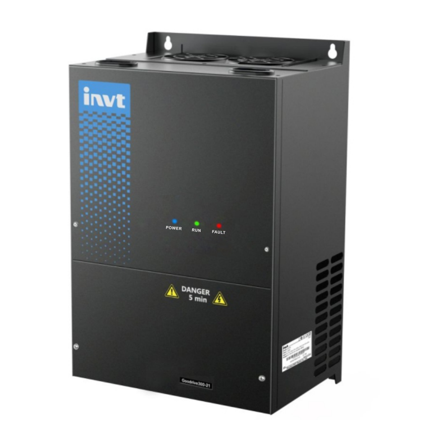
Goodrive300-21 integrated machine for air compressor Instruction for panel display 3. Instruction for panel display The panel of Goodrive300-21 series air compressor integrated machine carries three LED indicators (fault, running, power). The position and display state of the indicators are illustrated as below: Fault... -
Page 14: Debugging Guidance
Goodrive300-21 integrated machine for air compressor Debugging guidance 4. Debugging guidance 4.1. Wiring diagram of integrated machine system Remote data collection terminal (optional) RS485 joint control E-stop Customized Internal fault input signal signal output Oil gas temp. Auxillary temp. Solenoid valve Exhaust Auxillary Contactor coil... - Page 15 Goodrive300-21 integrated machine for air compressor Debugging guidance Main motor AC power R, S, T, ground wire through hole U1, V1, W1, ground wire through hole Through-hole of Through-hole of controlling cable controlling cable Through-hole of U2, V2, W2, ground wire through hole optional parts cable Ventilation hole at the bottom of integrated machine...
- Page 16 Goodrive300-21 integrated machine for air compressor Debugging guidance AC power Main motor U1, V1, W1 through R, S, T through hole hole Through hole of Through hole of controlling cable controlling cable Through hole of optional parts U2, V2, W2, ground wire cable through hole Through hole of...
-
Page 17: Function Debugging Procedures
Goodrive300-21 integrated machine for air compressor Debugging guidance Note: 1. There are two controlling cable through holes on the top and at the bottom of the integrated machine cabinet, users can select which through-hole to use based on wiring condition. It is recommended that the controlling cable is routed via top through-hole to realize separation between controlling cable and motor cable and reduce interference. - Page 18 Goodrive300-21 integrated machine for air compressor Debugging guidance 3. Click “click to enter” and enter working environment interface: Fig 4.7 Working interface 4. Click “menu” in above interface and the interface is as below: Fig 4.8 Menu interface...
- Page 19 Goodrive300-21 integrated machine for air compressor Debugging guidance 5. Click “system config” in touch screen menu and enter system configuration page, the interface is shown as below: Fig 4.9 System configuration interface The fan inverter is enabled by default. Debug according to the debugging procedures. Step 1: Click “Dbg guidelines”...
- Page 20 Goodrive300-21 integrated machine for air compressor Debugging guidance “asynchronous motor, it is necessary to set max. frequency, rated frequency, rated power, rated voltage, rated current, rated rotation speed and carrier frequency. Fig 4.11 Master parameter setting interface After setting motor parameters according to actual motor nameplate parameters, click “para autotuning”...
- Page 21 Goodrive300-21 integrated machine for air compressor Debugging guidance Fig 4.12 Interface for setting fan parameters Step 3: Click “Next page” to enter “system parameter configuration” or click “BACK” to return to system configuration. In system configuration interface, click “system para set”. S1 acts as E-stop switch and select NO/NC according to the polarity of E-stop switch.
- Page 22 Goodrive300-21 integrated machine for air compressor Debugging guidance Fig 4.14 Debugging mode interface Click “jog” for motor and fan to determine motor rotation direction; click “load” or “unload” to test the action of solenoid valve. Click “BACK” to enter system configuration, then, click “menu” to return menu interface.
- Page 23 Goodrive300-21 integrated machine for air compressor Debugging guidance 7. Click “maintenance para” in touch screen menu and the interface is shown as below: Fig 4.16 Maintenance parameter interface 8. Click “protection para” in the menu and the interface is shown as below: Fig 4.17 Protection parameter interface...
- Page 24 Goodrive300-21 integrated machine for air compressor Debugging guidance 9. Click “running info” in the menu and the interface is shown as below: Fig 4.18 Running information interface 10. After adjusting user parameter, factory parameter, maintenance parameter according to touch screen manual, return to “workspace” interface and click “start” to run. Note: All the parameters displayed in “4.3 function debugging procedures”...
-
Page 25: Function Instruction
Goodrive300-21 integrated machine for air compressor Function instruction 5. Function instruction “○” : means the setting value of this parameter is modifiable when the inverter is in stop and running state; “◎”: means the setting value of this parameter is non-modifiable when the inverter is in running state; “●”: means the value of this parameter is the actual detected record value and cannot be modified. - Page 26 Goodrive300-21 integrated machine for air compressor Function instruction Function Default Name Detailed instruction Modify code value P00.06 A frequency command 0: Keypad digital setting ○ selection 1: Analog P1-setting 2: Reserved 3: Analog P2-setting 4: Reserved 5: Reserved 6: Multi-step speed running setting B frequency command ○...
- Page 27 Goodrive300-21 integrated machine for air compressor Function instruction Function Default Name Detailed instruction Modify code value 3: Static autotuning 2 (partial autotuning) 0: Invalid ○ P00.16 AVR function selection 1: Valid the whole time 0: G type ◎ P00.17 Inverter type 1: P type 0: No operation 1: Restore to default value...
- Page 28 Goodrive300-21 integrated machine for air compressor Function instruction Function Default Name Detailed instruction Modify code value model Depend Stator resistance of ○ P02.06 0.001–65.535Ω AM 1 model Depend Rotor resistance of AM ○ P02.07 0.001–65.535Ω model Depend Leakage inductance of ○...
- Page 29 Goodrive300-21 integrated machine for air compressor Function instruction Function Default Name Detailed instruction Modify code value Depend ◎ P02.19 Rated current of SM 1 0.8–6000.0A model Depend Stator resistance of ○ P02.20 0.001–65.535Ω SM 1 model Depend D-axis inductance of ○...
- Page 30 Goodrive300-21 integrated machine for air compressor Function instruction Function Default Name Detailed instruction Modify code value time(min) Current 150% 180% 200% 116% Setting range: 20.0%–120.0% Power correction ○ P02.28 0.00–3.00 1.00 coefficient of motor 1 Parameter display 0: Display based on motor type ○...
- Page 31 Goodrive300-21 integrated machine for air compressor Function instruction Function Default Name Detailed instruction Modify code value proportional coefficient The default value of P03.09 and P03.10 is different in differing power ranges. Set power model ranges by touch screen and they will be set to the following empirical parameters after autotuning.
- Page 32 Goodrive300-21 integrated machine for air compressor Function instruction Function Default Name Detailed instruction Modify code value motor 1 1: Multi-point V/F curve 2: 1.3 power of torque reduction V/F curve 3: 1.7 power of torque reduction V/F curve 4: 2.0 power of torque reduction V/F curve 5: Reserved Torque elevator of ○...
- Page 33 Goodrive300-21 integrated machine for air compressor Function instruction Function Default Name Detailed instruction Modify code value P04.35 Reactive closed-loop 0–3000 ○ integral coefficient ◎ P05.00 Reserved Reserved 0: No function 1: Forward rotation running 2: Reverse rotation running 3: Three-wire running control 4: Forward rotation jogging 5: Reverse rotation jogging 6: Coast to stop...
- Page 34 Goodrive300-21 integrated machine for air compressor Function instruction Function Default Name Detailed instruction Modify code value selection input terminals. When the bit is set to 0, input terminal is positive polarity; When the bit is set to 1, input terminal is negative polarity BIT8 BIT7...
- Page 35 Goodrive300-21 integrated machine for air compressor Function instruction Function Default Name Detailed instruction Modify code value ○ P05.36 Input filter time of P1 0.000s–10.000s 0.200s Lower limit value of ○ P05.37 0.00V–P05.39 0.00V Corresponding setting ○ P05.38 -100.0%–100.0% -12.5% of PT1 lower limit Upper limit value of ○...
- Page 36 Goodrive300-21 integrated machine for air compressor Function instruction Function Default Name Detailed instruction Modify code value 23: MODBUS communication virtual terminal output 24–26: Reserved 27: Start/stop control of auxiliary motor (air compressor-specific) 28: Solenoid valve control output (air compressor-specific) 29: Cooling fan control of main motor (air compressor-specific) 30: Reserved ○...
- Page 37 Goodrive300-21 integrated machine for air compressor Function instruction Function Default Name Detailed instruction Modify code value parameters 1: Upload function parameters to the keypad 2: Download keypad function parameters to the machine (including motor parameters) 3: Download keypad function parameters to the machine (excluding P02 and P12 parameter groups) 4: Download keypad function parameters to the...
- Page 38 Goodrive300-21 integrated machine for air compressor Function instruction Function Default Name Detailed instruction Modify code value ● P07.25 Factory bar code 5 0x0000–0xFFFF ● P07.26 Factory bar code 6 0x0000–0xFFFF 0: No fault 1: Inverter unit U phase protection (OUt1) 2: Inverter unit V phase protection (OUt1) 3: Inverter unit W phase protection (OUt1) 4: Overcurrent at acceleration (OC1)
- Page 39 Goodrive300-21 integrated machine for air compressor Function instruction Function Default Name Detailed instruction Modify code value 38: Phase sequence fault (PSF) ● P07.28 Type of last one fault Type of the last two ● P07.29 faults Type of the last three ●...
- Page 40 Goodrive300-21 integrated machine for air compressor Function instruction Function Default Name Detailed instruction Modify code value selection 1: Reserved 2: Analog P2-feedback 3: Reserved 4: MODBUS communication feedback 5–7: Reserved 8: Pressure feedback for air compressor-specific function 0: PID output is positive characteristic: namely, the feedback signal is larger than PID reference, which requires the inverter output frequency to decrease to enable PID to reach balance, such...
- Page 41 Goodrive300-21 integrated machine for air compressor Function instruction Function Default Name Detailed instruction Modify code value The shorter the integral time, the stronger the adjustment intensity. Setting range: 0.00–10.00s It determines the intensity of the adjustment made by PID regulator against the change rate of deviation between PID feedback quantity and reference quantity.
- Page 42 Goodrive300-21 integrated machine for air compressor Function instruction Function Default Name Detailed instruction Modify code value 0: Continuing integral adjustment after the frequency reaches upper/lower limit 1: Stop integral adjustment after the frequency reaches upper/lower limit LED hundreds: 0: consistent with the set direction 1: can be contrary to the set direction ○...
- Page 43 Goodrive300-21 integrated machine for air compressor Function instruction Function Default Name Detailed instruction Modify code value 0x00–0x11 Ones: Current-limit action 0: Current-limit action is invalid 1: Current-limit action is valid all the time ◎ P11.05 Current-limit selection Tens: Hardware current-limit overload alarm 0: Hardware current-limit overload alarm is valid 1: Hardware current-limit overload alarm is invalid...
- Page 44 Goodrive300-21 integrated machine for air compressor Function instruction Function Default Name Detailed instruction Modify code value (reserved) High frequency ◎ P13.06 0.0–300.0% rated motor voltage 40.0% overlay voltage ○ P13.08 Control parameter 1 0–FFFF 0x120 ○ P13.09 Control parameter 2 0–300.00 5.00 Adjust the responsiveness of anti-maladjustment function.
- Page 45 Goodrive300-21 integrated machine for air compressor Function instruction Function Default Name Detailed instruction Modify code value control modes) 0x00–0x11 LED ones: Writing operation acts 0: There is response for writing operation Communication ○ P14.06 1: No response for writing operation 0x00 processing action LED tens: Communication encryption processing...
- Page 46 Goodrive300-21 integrated machine for air compressor Function instruction Function Default Name Detailed instruction Modify code value Display the analog input voltage value of PT1 channel. Connect PT100 thermal resistor temperature sensor in air compressor mode, and different resistance value will be generated under different temperature Different resistance value ●...
- Page 47 Goodrive300-21 integrated machine for air compressor Function instruction Function Default Name Detailed instruction Modify code value Running time of this ● P17.26 0–65535m time ● P17.28 ASR controller output -300.0%–300.0% (rated motor current) 0.0% Magnetic pole angle of ● P17.29 0.0–360.0 Phase compensation ●...
- Page 48 Goodrive300-21 integrated machine for air compressor Function instruction Function Default Name Detailed instruction Modify code value 1: head temperature PT2, auxiliary temperature 0.00–20.00 Mpa It is related to actual range of pressure sensor. Upper limit of pressure 1.60Mp ◎ P18.04 The voltage corresponds to P18.04 is P05.34 sensor P1 Note: This value stays in current set value during...
- Page 49 Goodrive300-21 integrated machine for air compressor Function instruction Function Default Name Detailed instruction Modify code value the head temperature. Setting range:-20–150 Stop temperature of ○ P18.09 65℃ the fan ○ P18.10 Setting temperature 75℃ P18.12–P00.04 (upper limit of running frequency) Lower limit frequency It is the min.
- Page 50 Goodrive300-21 integrated machine for air compressor Function instruction Function Default Name Detailed instruction Modify code value pre-alarm by changing BIT8 of P19.13 to 1. When the current exhaust pressure is detected to be above P18.18, the system releases pressure alarm by changing BIT10 of P19.13 to 1 and emergency stop will be applied.
- Page 51 Goodrive300-21 integrated machine for air compressor Function instruction Function Default Name Detailed instruction Modify code value strong the intensity may cause temperature oscillation. It is viable to make adjustment based on factory value according to actual conditions. Setting range: 0.00–1.00 It is used to limit the output value of temperature Upper limit of PID adjustment.
- Page 52 Goodrive300-21 integrated machine for air compressor Function instruction Function Default Name Detailed instruction Modify code value corresponds to PT100 at 150℃, read the voltage value of P17.22 and input it to P18.33 Setting range: 0.00–10.00V Note: The value stays in current set value during restoring to factory value.
- Page 53 Goodrive300-21 integrated machine for air compressor Function instruction Function Default Name Detailed instruction Modify code value larger than P18.41, system releases auxiliary pressure alarm by changing BIT9 of P19.14 to 1 and emergency stop will be applied. 0: Temperature PID 1: Analog P2 Reference mode of fan 2: 485 communication (address 0X201C, writing...
- Page 54 Goodrive300-21 integrated machine for air compressor Function instruction Function Default Name Detailed instruction Modify code value P19.05–P19.09 displays the working time of corresponding parts. Range: 0–65535h The set time of ● P19.01 maintenance on part 2 The set time of ●...
- Page 55 Goodrive300-21 integrated machine for air compressor Function instruction Function Default Name Detailed instruction Modify code value Current temp. P18.03=0 P19.12 P18.28 P18.29 P17.20 PT1 input voltage Current temp. P18.03=1 P19.12 P18.32 P18.33 P17.22 PT2 input voltage Range: -20–150℃ 0000–0xFFFF BIT0: Air filter block signal 1: Fault;...
- Page 56 Goodrive300-21 integrated machine for air compressor Function instruction Function Default Name Detailed instruction Modify code value 1: Temperature alarm; 0: normal BIT12: Pressure signal 1: Pressure signal fault: 0: normal BIT13: Temperature signal 1: Temperature signal fault; 0: normal BIT14: Low temperature protection 1: Low temperature alarm;...
- Page 57 Goodrive300-21 integrated machine for air compressor Function instruction Function Default Name Detailed instruction Modify code value 2: Fault 3: Emergency-stop 4: Under-voltage 5: Alarm 6: Sleep 7: Stopping 8: Restart delay Accumulated running ● P19.16 Display range: 0–65535h time of the device Accumulated loading ●...
- Page 58 Goodrive300-21 integrated machine for air compressor Function instruction Function Default Name Detailed instruction Modify code value Current auxiliary pressure P18.37=0 P18.38 P19.20 P2 input P05.42 P17.21 P05.44 Current auxiliary pressure voltage P18.37=1 P18.04 P19.20 P1 input voltage P05.32 P17.19 P05.34 Range: 0.00–655.35Mpa It displays the auxiliary temperature value detected currently...
- Page 59 Goodrive300-21 integrated machine for air compressor Function instruction Function Default Name Detailed instruction Modify code value 2: lack of R phase 3: lack of S phase 4: lack of T phase...
-
Page 60: Instruction Of Air Compressor Control Logic
Goodrive300-21 integrated machine for air compressor Function instruction 5.3. Instruction of air compressor control logic (1) The control logic of air compressor is shown as below: Stand-by Starting command Restart delay P18.16 is passed No-load running Stop delay Stop command P18.14 is passed The first loading after starting... - Page 61 Goodrive300-21 integrated machine for air compressor Function instruction (2) The pressure and running frequency control of air compressor during running is shown as below: Current pressure P18.05 P18.07 P18.06 Time Current running frequency P00.04 P18.11 P18.12 P01.15 Time In above figure, P18.05 is unloading pressure, P18.06 is loading pressure and P18.07 is the set pressure.
- Page 62 Goodrive300-21 integrated machine for air compressor Function instruction pressure is detected to be below P18.06, automatic loading will be applied. During loading running, the rotation speed of the master will be controlled by pressure PID. P18.07 is the air supply pressure when setting stable running of air compressor, the inverter keeps exhaust pressure constant by regulating the rotation speed of the master.
-
Page 63: Fault Information And Solution
Goodrive300-21 integrated machine for air compressor Fault information and solution 6. Fault information and solution 6.1. Faults and countermeasures for integrated machine Table 6.1 Faults and countermeasures for Goodrive300-21 air compressor integrated machine Fault code Fault type Possible cause What to do ... - Page 64 Goodrive300-21 integrated machine for air compressor Fault information and solution Fault code Fault type Possible cause What to do The motor stall or load Check the load and adjust transients is too strong the torque lift Increase ACC time ...
- Page 65 Goodrive300-21 integrated machine for air compressor Fault information and solution Fault code Fault type Possible cause What to do Empty the motor load and parameters gained from autotunting and the standard re-identify Check the motor parameter is huge ...
- Page 66 Goodrive300-21 integrated machine for air compressor Fault information and solution Fault code Fault type Possible cause What to do downloading disconnection occurred and rule out interference The keypad wire is too long error source Replace the hardware and suffers from strong interference and ask for service ...
- Page 67 Goodrive300-21 integrated machine for air compressor Fault information and solution Fig 6.1 E_FAN fault display interface Click “menu” in fig 6.1 interface, and the interface is shown in Fig 4.8; Click “platform information” in the interface and the interface is shown in below fig: Click “keypad”...
-
Page 68: Fault And Countermeasures For Air Compressor Device
Goodrive300-21 integrated machine for air compressor Fault information and solution Deal with the fault code displayed in the virtual keypad according to the fault countermeasures listed in Table 6.1. 6.2. Fault and countermeasures for air compressor device Fault and countermeasures for air compressor device are listed as below: P19.13 State type Possible cause... - Page 69 Goodrive300-21 integrated machine for air compressor Fault information and solution P19.13 State type Possible cause Corrective measures alarm detected by PT1 is larger than are set correctly; the alarm temperature set by Check if the fan operates normally; P18.20 The fan power is too small for effective cooling;...
- Page 70 Goodrive300-21 integrated machine for air compressor Fault information and solution P19.14 State type Possible cause Corrective measures detection is dropped Detect if PT100 wiring is normal Auxiliary Temperature detection sensor is BIT6=1 temperature PT100 sensor is disconnected abnormal signal fault Temperature detection input circuit is abnormal The actual pressure detected...
-
Page 71: Appendix A. Product Dimension
Goodrive300-21 series dual inverter integrated machine for air compressor Appendix A Appendix A. Product dimension A.1. Wall installation dimension Fig A.1 Wall installation diagram for 220V 7.5–18.5kW/380V 15–37kW Table A.1 Wall installation dimension for 220V 7.5–18.5kW/380V 15–37kW (unit: mm) Inverter... -
Page 72: Floor Installation Dimension (With Top Cover)
Goodrive300-21 series dual inverter integrated machine for air compressor Appendix A Table A.2 Wall installation dimension for 220V 22–45kW/380V 45–90kW (unit: mm) Inverter Diameter of specification installation bore 220V 22–45kW 380V 45–90kW A.2. Floor installation dimension (with top cover) Bottom view... -
Page 73: Floor Installation Dimension (Without Top Cover)
Goodrive300-21 series dual inverter integrated machine for air compressor Appendix A A.3. Floor installation dimension (without top cover) 仰视图 左视图 正视图 Fig A.4 Floor installation (w/o top cover) for 220V 7.5–45kW/380V 15–90kW Table A.4 Floor installation (w/o top cover) dimension for 220V 7.5–45kW/380V 15–90kW (unit: mm) - Page 74 Goodrive300-21 series dual inverter integrated machine for air compressor Appendix A Product weight N.W(kg) G.W (kg) Packaging dimension (mm) 220V 7.5–11kW/380V 15–22kW 310x220x35 (top cover) 220V 15–18.5kW/380V 30–37kW 360x240x40 (top cover) 220V 22–45kW/380V 45–90kW 430x295x35 (top cover) 220V 7.5–11kW/380V 15kW–22kW...
-
Page 75: Appendix B. Optional Parts And Accessories
Goodrive300-21 series dual inverter integrated machine for air compressor Appendix B Appendix B. Optional parts and accessories Accessories Installation position Power consumption detection Externally installed during wall installation, and built-in installation component can be available if the optional floor stand is installed. - Page 76 Goodrive300-21 series dual inverter integrated machine for air compressor Appendix B POWER connection terminal of integrated machine POWER Control board of Power collection integrated machine module CN15 interface +24V Power 485+ RS-485 485- UA UB UC UA UB UC AC power input...
- Page 77 Goodrive300-21 series dual inverter integrated machine for air compressor Appendix B 1. The cable on AC power input side should go through P1 side of the transformer and goes out from P2 side; 2. R phase should go through L3 hole, S phase through L2 hole and T phase through L1 hole;...
- Page 78 Goodrive300-21 series dual inverter integrated machine for air compressor Appendix B B.1.4. Debugging 1. Installing and wiring according to the requirements described in B.1.1, B.1.2 and B.1.3. After confirming the installation and wiring is correct, click start button in “system configuration” page on the touch screen to enable ammeter function.
-
Page 79: Contactor Component
Goodrive300-21 series dual inverter integrated machine for air compressor Appendix B B.2. Contactor component When the main motor and its cooling fan is connected in non-coaxial way, it is recommended to install the optional contactor component to control the operation of main motor cooling fan. The optional contactor component is available from our company. - Page 80 Goodrive300-21 series dual inverter integrated machine for air compressor Appendix B B.2.3. Installation steps for fuse pedestal The fuse pedestal must be installed according to below procedures, otherwise any wiring attempt would failure Step 1: Connect the cable to the bottom of the two pedestals respectively. The yellow cable (cable mark is FU-2) should connected to the left side while the green cable (cable mark is FU-4) should be connected to the right side;...
-
Page 81: Power Detection Component And Contactor Component
Goodrive300-21 series dual inverter integrated machine for air compressor Appendix B B.2.4. Dimension of contactor component 35mm standard guide rail installation Fig B.9 Contactor dimension (unit: mm) M4 fixation screw Fix this part with M4 screw 44.4 19.5 55.5 ( include dimension of transparent cover )... -
Page 82: Remote Data Collection Terminal Component
Goodrive300-21 series dual inverter integrated machine for air compressor Appendix B POWER connection terminal of integrated machine POWER Integrated machine Power collection control board module CN15 interface +24V Power 485+ RS-485 485- UA UB UC METER connection terminal of the integrated... - Page 83 Goodrive300-21 series dual inverter integrated machine for air compressor Appendix B Name Model Qty. Remark collection module Ribbon B.4.2. Guidance on electrical wiring The electrical wiring diagram of remote data collection terminal is shown as below: Remote data collection Antenna interface...
-
Page 84: Drip-Proof Top Cover
“valid” for GPRS operation enabling in “protection parameter” interface, it is viable to give reset command and modify parameters; if selecting “invalid”, state parameters will be read-only. Users can log onto the server (iot.invt.com:10000) with the account and password provided by INVT to check whether remote data terminal module is connected to internet. - Page 85 Goodrive300-21 series dual inverter integrated machine for air compressor Appendix B Name Model Qty. Remark 220V 7.5–11kW M5×10 380V 15–22kW 220V 15–18.5kW Combination screw M4×10 380V 30–37kW 220V 22–45kW M4×10 380V 45– 90kW 220V 7.5–11kW 285×205 380V 15–22kW 220V 15–18.5kW Top cover 335×225...
-
Page 86: Floor Installation Pedestal
Goodrive300-21 series dual inverter integrated machine for air compressor Appendix B B.6. Floor installation pedestal B.6.1. Open package list The default installation mode for Goodrive300-21 is wall installation. If Floor installation is needed, users can install the pedestal for floor installation. The package list is shown as below:... - Page 87 Goodrive300-21 series dual inverter integrated machine for air compressor Appendix B B.6.2. Installation diagram of the pedestal Integrated machine Pedestal Combination screw Fig B.17 Installation diagram of the pedestal Note: If users need to install power detection component or contactor component, it is recommended to install the components onto the pedestal first, then, install the pedestal onto the integrated machine.
- Page 88 Goodrive300-21 series dual inverter integrated machine for air compressor Appendix B Grounding of the shielded cable of Remote data collection remote data collection terminal terminal Antenna Connection terminal Through-hole of AC power ground cable R phase through-hole of AC power...
-
Page 89: Touch Screen
Goodrive300-21 series dual inverter integrated machine for air compressor Appendix B B.6.5. Floor wiring process For changing from wall installation to floor installation, an optional pedestal can do the trick. Control cable Control cable Power collection module Communication cable Connection cable of... - Page 90 Goodrive300-21 series dual inverter integrated machine for air compressor Appendix B RS485 communication cable Wiring of emergency-stop signal Output voltage Pressure sensor PT100 temp. sensor 220/110VAC interface interface Multi-function terminal 24V 4-20mA GD300-21 control board Fig B.21 Wiring of standard cable of touch screen Note: 1.
-
Page 91: Appendix C. Communication Protocol
Goodrive300-21 series dual inverter integrated machine for air compressor Appendix C Appendix C. Communication protocol C.1. Application mode of the inverter The Modbus protocol of the inverter is RTU mode and the physical layer is 2-wire RS485. C.1.1. RS485 The interface of RS485 works on semiduplex and its data signal applies differential transmission which is called balance transmission, too. - Page 92 Goodrive300-21 series dual inverter integrated machine for air compressor Appendix C C.2.4. Command code: 10H, continuous writing Command code 10H means that if the master writes data to the inverter, the data number depends on the “data number” in the command code. The max. continuous reading number is 16.
- Page 93 Goodrive300-21 series dual inverter integrated machine for air compressor Appendix C Function Address Data meaning instruction instruction definition characteristic The upper limit frequency setting during forward 2005H rotation(0–Fmax(unit: 0.01Hz)) The upper limit frequency setting during reverse 2006H rotation(0–Fmax(unit: 0.01Hz)) The upper limit torque of electromotion torque 2007H (0–3000, 1000 corresponds to the 100.0% of the...
- Page 94 Goodrive300-21 series dual inverter integrated machine for air compressor Appendix C Function Address Data meaning instruction instruction definition characteristic BIT4:=1 Clear the working time of part 5 =0: invalid BIT5=1 Clear the working time of the device =0: invalid BIT6=1 Solenoid valve loading =0: Solenoid valve unloading The set time for maintenance on part 1;...
- Page 95 Goodrive300-21 series dual inverter integrated machine for air compressor Appendix C Function Address Data meaning instruction instruction definition characteristic Bit0: =0:bus voltage is not established =1:bus voltage is established Bi1–2:=00:motor 1 =01:motor 2 =10:motor 3 =11:motor 4 Bit3: =0:asynchronous motor =1:synchronous...
- Page 96 Goodrive300-21 series dual inverter integrated machine for air compressor Appendix C Function Address Data meaning instruction instruction definition characteristic Read high speed 3011H pulse 2 input Read current step of the multi-step 3012H speed External length 3013H External counting 3014H...
- Page 97 Goodrive300-21 series dual inverter integrated machine for air compressor Appendix C Code Name Meaning protection without password unlocking, it will report that the system is locked. The slave uses functional code fields and fault addresses to indicate it is a normal response or some error occurs (named as objection response).
-
Page 98: Appendix D. Common Emc Problems And Countermeasures
Goodrive300-21 series dual inverter integrated machine for air compressor Appendix D Appendix D. Common EMC problems and countermeasures D.1. Interference problems of meter switch and sensors Interference phenomena: The sensor signal (pressure, temperature, displacement, etc) is collected and displayed via HMI... -
Page 99: Unstoppable Or Shimmering Indicator Caused By Coupling Of Motor Cable
Goodrive300-21 series dual inverter integrated machine for air compressor Appendix D Check if the ends of A, B cable of the 485 communication bus are connected reversely. Check if the communication protocol (eg baud rate, data bit check, etc)of the inverter is in consistent with that of the upper PC;... -
Page 100: Leakage Current And Residual Current Device (Rcd)
Goodrive300-21 series dual inverter integrated machine for air compressor Appendix D d) Indicating buzzer Solution: Check and confirm the abnormal signal cable is routed with motor cable motor cable at a distance of at least 20cm; Connect in parallel the digital input terminal (S) used for start/stop control with other idle digital input terminals. -
Page 101: Problem Of Charged Device Shell
Goodrive300-21 series dual inverter integrated machine for air compressor Appendix D Solution to mal-operation of RCD (on the part of system distribution) a) Check and confirm the power cable is not immersed in water b) Check and confirm the cable is not broken or switched over;... - Page 102 66001- 00485 201903 (V1.3)
Need help?
Do you have a question about the Goodrive300-21 Series and is the answer not in the manual?
Questions and answers