Juniper EX2200 Series Hardware Manual
Juniper networks switch user manual
Hide thumbs
Also See for EX2200 Series:
- Hardware manual (354 pages) ,
- User manual (238 pages) ,
- Complete hardware manual (176 pages)

Related Manuals for Juniper EX2200 Series


Summary of Contents for Juniper EX2200 Series
- Page 1 Complete Hardware Guide for EX2200 Ethernet Switches Published: 2011-11-15 Revision 7 Copyright © 2011, Juniper Networks, Inc.
-
Page 2: Revision
Products made or sold by Juniper Networks or components thereof might be covered by one or more of the following patents that are owned by or licensed to Juniper Networks: U.S. Patent Nos. 5,473,599, 5,905,725, 5,909,440, 6,192,051, 6,333,650, 6,359,479, 6,406,312, 6,429,706, 6,459,579, 6,493,347, 6,538,518, 6,538,899, 6,552,918, 6,567,902, 6,578,186, and 6,590,785. - Page 3 END USER LICENSE AGREEMENT The Juniper Networks product that is the subject of this technical documentation consists of (or is intended for use with) Juniper Networks software. Use of such software is subject to the terms and conditions of the End User License Agreement (“EULA”) posted at http://www.juniper.net/support/eula.html...
- Page 4 Copyright © 2011, Juniper Networks, Inc.
-
Page 5: Table Of Contents
EX2200 Switches Hardware Overview ........3... - Page 6 Mounting an EX2200 Switch on a Wall ....... . .
- Page 7 Performing Initial Configuration ........125 EX2200 Switch Default Configuration ........125 Connecting and Configuring an EX Series Switch (CLI Procedure) .
- Page 8 Installation Instructions Warning ........165 Chassis Lifting Guidelines for EX2200 Switches ......166 Ramp Warning .
-
Page 9: List Of Figures
EX2200-C Switch Models ........ - Page 10 Inlet on an EX2200 Switch ........
- Page 11 Removing Switch Components ........
- Page 12 Complete Hardware Guide for EX2200 Ethernet Switches Copyright © 2011, Juniper Networks, Inc.
-
Page 13: Part 2 Planning For Switch Installation
Table 16: Optical Interface Support and Copper Interface Support for SFP Transceivers in EX2200-C Switches ....... . 43... - Page 14 Table 25: Parts List for EX2200 Switches ....... . 73...
-
Page 15: About This Topic Collection
Software features for EX Series switches are listed by platform and by Junos OS release in a standalone document. See This guide, Complete Hardware Guide for EX2200 Ethernet Switches, collects together information about the EX2200 switches. The release notes are at http://www.juniper.net/techpubs/en_US/junos11.4/... - Page 16 Complete Hardware Guide for EX2200 Ethernet Switches Title Complete Hardware Guide for EX4200 Ethernet Switches Complete Hardware Guide for EX4500 Ethernet Switches Complete Hardware Guide for EX6210 Ethernet Switches Complete Hardware Guide for EX8208 Ethernet Switches Complete Hardware Guide for EX8216 Ethernet Switches Complete Hardware Guide for the XRE200 External Routing Engine ®...
-
Page 17: Downloading Software
OS for EX Series Ethernet Switches, Release 11.4: User Interfaces Downloading Software You can download Junos OS for EX Series switches from the Download Software area http://www.juniper.net/customers/support/ Copyright © 2011, Juniper Networks, Inc. About This Topic Collection Description . To download the software, you must... -
Page 18: Documentation Symbols Key
Complete Hardware Guide for EX2200 Ethernet Switches have a Juniper Networks user account. For information about obtaining an account, see http://www.juniper.net/entitlement/setupAccountInfo.do Documentation Symbols Key Notice Icons Icon Meaning Informational note Caution Warning Laser warning Text and Syntax Conventions Convention Bold text like this... -
Page 19: Documentation Feedback
Document URL or title Page number if applicable Software version Your name and company Copyright © 2011, Juniper Networks, Inc. Description Enclose optional keywords or variables. Indicates a choice between the mutually exclusive keywords or variables on either side of the symbol. The set of choices is often enclosed in parentheses for clarity. -
Page 20: Requesting Technical Support
7 days a week, 365 days a year. Self-Help Online Tools and Resources For quick and easy problem resolution, Juniper Networks has designed an online self-service portal called the Customer Support Center (CSC) that provides you with the following features:... -
Page 21: Switch And Components Overview And Specifications
PART 1 Switch and Components Overview and Specifications EX2200 Switch Overview on page 3 Component Descriptions on page 13 Component Specifications on page 21 Copyright © 2011, Juniper Networks, Inc. - Page 22 Complete Hardware Guide for EX2200 Ethernet Switches Copyright © 2011, Juniper Networks, Inc.
-
Page 23: Ex2200 Switch Overview
Layer 2 and Layer 3 switching, routing, and security services. The same Junos OS code base that runs on EX Series switches also runs on all Juniper Networks J Series, M Series, MX Series, and T Series routers and SRX Series services gateways. -
Page 24: Uplink Ports
Surface” on page Security Slots Each EX2200-C switch model has security slots on the left and right panels of the chassis. The security slots allow you to lock and secure the chassis in the installation site using “Mounting an EX2200 Switch on a Desk or Other Level “Optical Interface... -
Page 25: Power Over Ethernet (Poe) Ports
The remainder of this topic uses the term PoE to refer to both PoE and PoE+ unless there is a need to distinguish between the two. Front Panel of an EX2200 Switch The front panel of an EX2200 switch except the EX2200-C switch models consists of the following components: Network ports—depending on the switch model, either of:... -
Page 26: Figure 1: Front Panel Of An Ex2200 Switch With 48 Gigabit Ethernet Ports
Complete Hardware Guide for EX2200 Ethernet Switches Figure 1: Front Panel of an EX2200 Switch with 48 Gigabit Ethernet Ports Figure 2: Front Panel of an EX2200 Switch with 24 Gigabit Ethernet Ports The front panel of an EX2200-C switch consists of the following components: Network ports—depending on the switch model, either of:... -
Page 27: Rear Panel Of An Ex2200 Switch
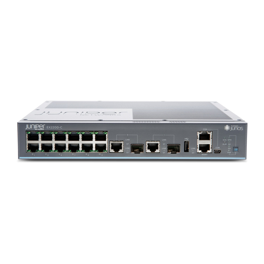
Figure 4: Front Panel of an EX2200-C Switch with 12 Gigabit Ethernet Ports (non-PoE) Rear Panel of an EX2200 Switch The rear panel of the EX2200 switch except the EX2200-C switch models consists of the following components: Management Ethernet port... -
Page 28: Ex2200 Switch Models
Site Preparation Checklist for EX2200 Switches on page 51 EX2200 Switch Models The EX2200 switch is available with 12, 24, or 48 built-in network ports with full Power over Ethernet (PoE) capability (all 12, 24, or 48 built-in network ports support PoE) or no PoE capability. -
Page 29: Chassis Physical Specifications For Ex2200 Switches
Related EX2200 Switches Hardware Overview on page 3 Documentation Chassis Physical Specifications for EX2200 Switches The EX2200 switch chassis is a rigid sheet-metal structure that houses the hardware components. switch chassis. Table 2: Physical Specifications of the EX2200 Switch Chassis... -
Page 30: Ex2200 Switch Hardware And Cli Terminology Mapping
Installing and Connecting an EX2200 Switch on page 71 EX2200 Switch Hardware and CLI Terminology Mapping This topic describes the hardware terms used in EX2200 switch documentation and the corresponding terms used in the Junos OS command line interface (CLI). See... - Page 31 Table 3: CLI Equivalents of Terms Used in Documentation for EX2200 Switches (continued) Hardware Item (as Description (as displayed in the CLI) displayed in the CLI) One of the following: 12x 10/100/1000 BASE-T 24x 10/100/1000 BASE-T 48x 10/100/1000 BASE-T One of the following:...
- Page 32 Complete Hardware Guide for EX2200 Ethernet Switches Copyright © 2011, Juniper Networks, Inc.
-
Page 33: Component Descriptions
Cooling System and Airflow in an EX2200 Switch on page 19 Chassis Status LEDs in EX2200 Switches The front panel of an EX2200 switch has two chassis status LEDs labeled SYS and ALM on the far right side of the panel. See... -
Page 34: Network Port And Uplink Port Leds In Ex2200 Switches
Understanding Alarm Types and Severity Levels on EX Series Switches Network Port and Uplink Port LEDs in EX2200 Switches Each network port and uplink port on the front panel of an EX2200 switch has two LEDs that indicate link/activity and port status. Each dual-purpose uplink port in an EX2200-C switch has two pairs of LEDs that indicate the link/activity status, one pair for each of the two ports that constitute the dual-purpose uplink port. -
Page 35: Figure 10: Leds On The Uplink Ports And Port Status Mode Leds In An Ex2200 Switch Except The Ex2200-C Switch Model
Port 1 Figure 11: Port status mode LEDs of the Dual-purpose uplink Ports of an EX2200-C Switch Table 5 on page 15 Table 5: Link/Activity LED on the Network Ports and Uplink Ports in EX2200 Switches Color Link/Activity Green Figure 9 on page indicate the status of one of the four port parameters—speed, duplex mode, administrative... -
Page 36: Table 6: Status Led On The Network Ports, Uplink Ports, And Dual-Purpose Uplink Ports In Ex2200 Switches
Three blinks per second—1000 Mbps The speed indicators for uplink ports are: On steadily—1000 Mbps Off—10/100 Mbps The speed indicators for dual-purpose uplink ports of EX2200-C switch model are: One blink per second—10 Mbps Two blinks per second—100 Mbps Three blinks per second—1000 Mbps Indicates the duplex mode. -
Page 37: Management Port Leds In Ex2200 Switches
Configuring Gigabit Ethernet Interfaces (J-Web Procedure) Management Port LEDs in EX2200 Switches The management port on an EX2200 switch has two LEDs that indicate link/activity and port status. The EX2200 switches except the EX2200-C switch models have the management port on the rear panel and the EX2200-C switch has the management port on the front panel. -
Page 38: Power Supply In Ex2200 Switches
Power Supply in EX2200 Switches The power supply in EX2200 switches is built in along the rear panel of the chassis, with an AC power cord inlet or DC power terminals on the rear panel to connect power to the switch. -
Page 39: Cooling System And Airflow In An Ex2200 Switch
In the PoE models of these switches, there is an additional fan in the power supply. In the EX2200-C switch the cooling is done by the vents on top and sides of the chassis in non-PoE models and by heatsinks in PoE+ models. Do not block the vents on the chassis. -
Page 40: Figure 15: Airflow Through Poe Models Of Ex2200 Switches Except The Ex2200-C Switch Models
Complete Hardware Guide for EX2200 Ethernet Switches Figure 15: Airflow Through PoE Models of EX2200 Switches Except the EX2200-C Switch Models Under normal operating conditions, the fans operate at a moderate speed to reduce noise. Temperature sensors in the chassis monitor the temperature within the chassis. -
Page 41: Component Specifications
USB Port Specifications for an EX Series Switch on page 21 Mini-USB Port Specifications for an EX2200 Switch on page 22 Network Port Connector Pinout Information for an EX2200 Switch on page 23 Console Port Connector Pinout Information for an EX Series Switch on page 23... -
Page 42: Mini-Usb Port Specifications For An Ex2200 Switch
Booting an EX Series Switch Using a Software Package Stored on a USB Flash Drive Mini-USB Port Specifications for an EX2200 Switch The EX2200-C switch, the compact, fanless model, has two management console ports: an RJ-45 port, and a Mini-USB Type-B port. -
Page 43: Network Port Connector Pinout Information For An Ex2200 Switch
Network Port Connector Pinout Information for an EX2200 Switch A network port on an EX2200 switch uses an RJ-45 connector to connect to a device. The port uses an autosensing RJ-45 connector to support a 10/100/1000Base-T connection. Two LEDs on the port indicate link/activity on the port and the port status. -
Page 44: Management Port Connector Pinout Information For An Ex2200 Switch
Connecting an EX Series Switch to a Management Console on page 115 Configuring the Console Port Type (CLI Procedure) Management Port Connector Pinout Information for an EX2200 Switch The management port on an EX2200 switch uses an RJ-45 connector to connect to a management device for out-of-band management. NOTE:... -
Page 45: Optical Interface Support In Ex2200 Switches
Connecting an EX Series Switch to a Network for Out-of-Band Management on page 113 Optical Interface Support in EX2200 Switches Uplink ports and dual-purpose uplink ports on the front panel in EX2200 switches support SFP transceivers. This topic describes the optical interfaces supported for those transceivers. -
Page 46: Table 14: Optical Interface Support And Copper Interface Support For Gigabit Ethernet Sfp Transceivers In Ex2200 Switches Except Ex2200-C
Complete Hardware Guide for EX2200 Ethernet Switches Table 14: Optical Interface Support and Copper Interface Support for Gigabit Ethernet SFP Transceivers in EX2200 Switches except EX2200-C Switches Ethernet Standard Specification 1000BASE-T Model Number Rate Connector Type Transmitter Wavelength Minimum Launch Power... - Page 47 Table 14: Optical Interface Support and Copper Interface Support for Gigabit Ethernet SFP Transceivers in EX2200 Switches except EX2200-C Switches (continued) Ethernet Standard Specification 1000BASE-SX Model Number Rate Connector Type Fiber Count Transmitter Wavelength Minimum Launch Power Maximum Launch Power...
- Page 48 Complete Hardware Guide for EX2200 Ethernet Switches Table 14: Optical Interface Support and Copper Interface Support for Gigabit Ethernet SFP Transceivers in EX2200 Switches except EX2200-C Switches (continued) Ethernet Standard Specification 1000BASE-LX Model Number Rate Connector Type Fiber Count Transmitter Wavelength...
- Page 49 Table 14: Optical Interface Support and Copper Interface Support for Gigabit Ethernet SFP Transceivers in EX2200 Switches except EX2200-C Switches (continued) Ethernet Standard Specification 1000BASE-BX-U Model Number Rate Connector Type Fiber Count Transmitter Wavelength Receiver Wavelength Minimum Launch Power Maximum Launch Power...
- Page 50 Complete Hardware Guide for EX2200 Ethernet Switches Table 14: Optical Interface Support and Copper Interface Support for Gigabit Ethernet SFP Transceivers in EX2200 Switches except EX2200-C Switches (continued) Ethernet Standard Specification 1000BASE-BX-D Model Number Rate Connector Type Fiber Count Transmitter Wavelength...
- Page 51 Table 14: Optical Interface Support and Copper Interface Support for Gigabit Ethernet SFP Transceivers in EX2200 Switches except EX2200-C Switches (continued) Ethernet Standard Specification 1000BASE-BX-U Model Number Rate Connector Type Fiber Count Transmitter Wavelength Receiver Wavelength Minimum Launch Power Maximum Launch Power...
- Page 52 Complete Hardware Guide for EX2200 Ethernet Switches Table 14: Optical Interface Support and Copper Interface Support for Gigabit Ethernet SFP Transceivers in EX2200 Switches except EX2200-C Switches (continued) Ethernet Standard Specification 1000BASE-BX-D Model Number Rate Connector Type Fiber Count Transmitter Wavelength...
- Page 53 Table 14: Optical Interface Support and Copper Interface Support for Gigabit Ethernet SFP Transceivers in EX2200 Switches except EX2200-C Switches (continued) Ethernet Standard Specification 1000BASE-BX-U Model Number Rate Connector Type Fiber Count Transmitter Wavelength Receiver Wavelength Minimum Launch Power Maximum Launch Power...
- Page 54 Complete Hardware Guide for EX2200 Ethernet Switches Table 14: Optical Interface Support and Copper Interface Support for Gigabit Ethernet SFP Transceivers in EX2200 Switches except EX2200-C Switches (continued) Ethernet Standard Specification 1000BASE-BX-D Model Number Rate Connector Type Fiber Count Transmitter Wavelength...
- Page 55 Table 14: Optical Interface Support and Copper Interface Support for Gigabit Ethernet SFP Transceivers in EX2200 Switches except EX2200-C Switches (continued) Ethernet Standard Specification 1000BASE-LX Model Number Rate Connector Type Fiber Count Transmitter Wavelength Minimum Launch Power Maximum Launch Power...
- Page 56 Complete Hardware Guide for EX2200 Ethernet Switches Table 14: Optical Interface Support and Copper Interface Support for Gigabit Ethernet SFP Transceivers in EX2200 Switches except EX2200-C Switches (continued) Ethernet Standard Specification 1000BASE-LH (or Model Number 1000BASE-ZX) Rate Connector Type Fiber Count...
-
Page 57: Table 15: Optical Interface Support For Fast Ethernet Sfp Transceivers In Ex2200 Switches Except Ex2200-C Switches
Table 15: Optical Interface Support for Fast Ethernet SFP Transceivers in EX2200 Switches except EX2200-C Switches Ethernet Standard Specification 100BASE-FX Model Number Rate Connector Type Fiber Count Transmitter Wavelength Minimum Launch Power Maximum Launch Power Minimum Receiver Sensitivity Maximum Input Power... - Page 58 Complete Hardware Guide for EX2200 Ethernet Switches Table 15: Optical Interface Support for Fast Ethernet SFP Transceivers in EX2200 Switches except EX2200-C Switches (continued) Ethernet Standard Specification 100BASE-LX Model Number Rate Connector Type Fiber Count Transmitter Wavelength Minimum Launch Power...
- Page 59 Table 15: Optical Interface Support for Fast Ethernet SFP Transceivers in EX2200 Switches except EX2200-C Switches (continued) Ethernet Standard Specification 100BASE-BX-U Model Number Rate Connector Type Fiber Count Transmitter Wavelength Receiver Wavelength Minimum Launch Power Maximum Launch Power Minimum Receiver Sensitivity...
- Page 60 Complete Hardware Guide for EX2200 Ethernet Switches Table 15: Optical Interface Support for Fast Ethernet SFP Transceivers in EX2200 Switches except EX2200-C Switches (continued) Ethernet Standard Specification 100BASE-BX-D Model Number Rate Connector Type Fiber Count Transmitter Wavelength Receiver Wavelength Minimum Launch Power...
- Page 61 Table 15: Optical Interface Support for Fast Ethernet SFP Transceivers in EX2200 Switches except EX2200-C Switches (continued) Ethernet Standard Specification 100BASE-LX40K Model Number Rate Connector Type Fiber Count Transmitter Wavelength Minimum Launch Power Maximum Launch Power Minimum Receiver Sensitivity Maximum Input Power...
- Page 62 Complete Hardware Guide for EX2200 Ethernet Switches Table 15: Optical Interface Support for Fast Ethernet SFP Transceivers in EX2200 Switches except EX2200-C Switches (continued) Ethernet Standard Specification 100BASE-LH (or Model Number 100BASE-ZX) Rate Connector Type Fiber Count Transmitter Wavelength Minimum Launch Power...
-
Page 63: Table 16: Optical Interface Support And Copper Interface Support For Sfp Transceivers In Ex2200-C Switches
Maximum Launch Power Minimum Receiver Sensitivity Maximum Input Power Fiber Type Core/Cladding Size Fiber Grade Modal Bandwidth Distance Software Required Copyright © 2011, Juniper Networks, Inc. Chapter 3: Component Specifications Value EX-SFP-1GE-SX 1000 Mbps Dual 850 nm –9.5 dBm –3 dBm –21 dBm... - Page 64 Complete Hardware Guide for EX2200 Ethernet Switches Table 16: Optical Interface Support and Copper Interface Support for SFP Transceivers in EX2200-C Switches (continued) Ethernet Standard Specification Extended Temp SFP Model Number 1000BASE-SX Rate Connector Type Fiber Count Transmitter Wavelength Minimum Launch Power...
- Page 65 Maximum Input Power Fiber Type Core/Cladding Size Modal Bandwidth Transmitter Wavelength Distance Software Required Copyright © 2011, Juniper Networks, Inc. Chapter 3: Component Specifications Value EX-SFP-1FE-FX-EXT 1000 Mbps 1310 nm 2 km (1.2 miles) Junos OS for EX Series switches, Release 11.3...
- Page 66 Complete Hardware Guide for EX2200 Ethernet Switches Table 16: Optical Interface Support and Copper Interface Support for SFP Transceivers in EX2200-C Switches (continued) Ethernet Standard Specification 100BASE-FX Model Number Rate Connector Type Fiber Count Transmitter Wavelength Minimum Launch Power Maximum Launch Power...
- Page 67 Minimum Launch Power Maximum Launch Power Minimum Receiver Sensitivity Maximum Input Power Fiber Type Core/Cladding Size Modal Bandwidth Distance Software Required Copyright © 2011, Juniper Networks, Inc. Chapter 3: Component Specifications Value EX-SFP-1GE-LX 1000 Mbps Dual 1310 nm –9.5 dBm –3 dBm –25 dBm...
- Page 68 Complete Hardware Guide for EX2200 Ethernet Switches Table 16: Optical Interface Support and Copper Interface Support for SFP Transceivers in EX2200-C Switches (continued) Ethernet Standard Specification 1000BASE-LH (or Model Number 1000BASE-ZX) Rate Connector Type Fiber Count Transmitter Wavelength Minimum Launch Power...
-
Page 69: Planning For Switch Installation
PART 2 Planning for Switch Installation Site Preparation on page 51 Mounting and Clearance Requirements on page 57 Cable Specifications on page 63 Planning Power Requirements on page 65 Copyright © 2011, Juniper Networks, Inc. - Page 70 Complete Hardware Guide for EX2200 Ethernet Switches Copyright © 2011, Juniper Networks, Inc.
-
Page 71: Site Preparation
CHAPTER 4 Site Preparation Site Preparation Checklist for EX2200 Switches on page 51 General Site Guidelines on page 52 Site Electrical Wiring Guidelines on page 53 Environmental Requirements and Specifications for EX Series Switches on page 54 Site Preparation Checklist for EX2200 Switches The checklist in preparing a site for EX2200 switch installation. -
Page 72: General Site Guidelines
General Safety Guidelines and Warnings on page 155 Documentation General Site Guidelines on page 52 Installing and Connecting an EX2200 Switch on page 71 Mounting an EX2200 Switch on page 74 General Site Guidelines This topic applies to hardware devices in the EX Series product family, which includes switches and the XRE200 External Routing Engine. -
Page 73: Site Electrical Wiring Guidelines
Electromagnetic pulses (EMPs) caused by lightning damages unshielded conductors and electronic devices. Copyright © 2011, Juniper Networks, Inc. describes the factors you must consider while planning the electrical WARNING: It is particularly important to provide a properly grounded and shielded environment and to use electrical surge-suppression devices. -
Page 74: Environmental Requirements And Specifications For Ex Series Switches
AC Power Supply in a QFX3500 Switch Environmental Requirements and Specifications for EX Series Switches The switch must be installed in a rack or cabinet housed in a dry, clean, well-ventilated, and temperature-controlled environment. Ensure that these environmental guidelines are followed: The site must be as dust-free as possible, because dust can clog air intake vents and filters, reducing the efficiency of the switch cooling system. -
Page 75: Table 19: Ex Series Switch Environmental Tolerances
Maintain ambient airflow for normal switch operation. If the airflow is blocked or restricted, or if the intake air is too warm, the switch might overheat, leading to the switch temperature monitor shutting down the switch to protect the hardware components. - Page 76 Complete Hardware Guide for EX2200 Ethernet Switches Clearance Requirements for Airflow and Hardware Maintenance for EX4200 Switches Clearance Requirements for Airflow and Hardware Maintenance for EX4500 Switches Clearance Requirements for Airflow and Hardware Maintenance for an EX6210 Switch Clearance Requirements for Airflow and Hardware Maintenance for an EX8208 Switch Clearance Requirements for Airflow and Hardware Maintenance for an EX8216 Switch Copyright ©...
-
Page 77: Mounting And Clearance Requirements
The rack must meet the strength requirements to support the weight of the chassis. Mounting bracket hole The holes in the mounting brackets are spaced at 1 U (1.75 in. or 4.45 cm), so that the switch can spacing be mounted in any rack that provides holes spaced at that distance. -
Page 78: Cabinet Requirements For Ex2200 Switches
Mounting an EX2200 Switch on Two Posts of a Rack or Cabinet on page 81 Mounting an EX2200 Switch on Four Posts of a Rack or Cabinet on page 84 Mounting an EX2200 Switch in a Recessed Position in a Rack or Cabinet on page 88 Cabinet Requirements for EX2200 Switches You can mount the switch in a cabinet that contains a 19-in. -
Page 79: Table 21: Cabinet Requirements And Specifications For The Switch
Mounting an EX2200 Switch on Two Posts of a Rack or Cabinet on page 81 Mounting an EX2200 Switch on Four Posts of a Rack or Cabinet on page 84 Mounting an EX2200 Switch in a Recessed Position in a Rack or Cabinet on page 88 Copyright © 2011, Juniper Networks, Inc. -
Page 80: Requirements For Mounting An Ex2200 Switch On A Desktop Or Wall
Insert the screws into wall studs wherever possible to provide added support for the chassis. Use the wall-mount kit from Juniper Networks to mount the switch on a wall. The wall-mount kit is not part of the standard package and must be ordered separately. -
Page 81: Figure 17: Clearance Requirements For Airflow And Hardware Maintenance For
(22.1 cm) (26.9 cm) (48.2 cm) 6" (15.2 cm) Mounting bracket for airflow shows the airflow in PoE models of EX2200 switches, except for Figure 19 on page 62 shows the airflow non-PoE models of EX2200 Chassis front Fans Chassis rear... -
Page 82: Figure 19: Airflow Through Non-Poe Models Of Ex2200 Switches Except Ex2200-C Switch Models
Figure 19: Airflow Through Non-PoE Models of EX2200 Switches Except EX2200-C Switch Models If you are mounting an EX2200 switch in a rack or cabinet with other equipment, or if you are placing it on the desktop or floor near other equipment, ensure that the exhaust from other equipment does not blow into the intake vents of the chassis. -
Page 83: Chapter 6 Cable Specifications
For instructions on connecting a fiber-optic cable to the switch, see Fiber-Optic Cable to an EX Series Switch” on page Related Management Port Connector Pinout Information for an EX2200 Switch on page 24 Documentation Console Port Connector Pinout Information for an EX Series Switch on page 23 EX2200 Switches Hardware Overview on page 3 Copyright ©... - Page 84 Complete Hardware Guide for EX2200 Ethernet Switches Copyright © 2011, Juniper Networks, Inc.
-
Page 85: Planning Power Requirements
Power Specifications for EX2200 Switches on page 65 AC Power Cord Specifications for EX2200 Switches on page 66 Power Specifications for EX2200 Switches This topic describes the power supply electrical specifications for EX2200 switches. Table 22 on page 65 switches. -
Page 86: Ac Power Cord Specifications For Ex2200 Switches
Complete Hardware Guide for EX2200 Ethernet Switches Related AC Power Cord Specifications for EX2200 Switches on page 66 Documentation Power Supply in EX2200 Switches on page 18 General Safety Guidelines and Warnings on page 155 General Electrical Safety Guidelines and Warnings on page 179 AC Power Cord Specifications for EX2200 Switches A detachable AC power cord is supplied with the AC power supplies. -
Page 87: Figure 20: Ac Plug Types
Table 24 on page Figure 20: AC Plug Types Related Power Supply in EX2200 Switches on page 18 Documentation General Safety Guidelines and Warnings on page 155 General Electrical Safety Guidelines and Warnings on page 179 Prevention of Electrostatic Discharge Damage on page 180 Copyright ©... - Page 88 Complete Hardware Guide for EX2200 Ethernet Switches Copyright © 2011, Juniper Networks, Inc.
-
Page 89: Installing And Connecting The Switch And Switch Components
PART 3 Installing and Connecting the Switch and Switch Components Installing the Switch on page 71 Installing Switch Components on page 99 Connecting the Switch on page 103 Performing Initial Configuration on page 125 Copyright © 2011, Juniper Networks, Inc. - Page 90 Complete Hardware Guide for EX2200 Ethernet Switches Copyright © 2011, Juniper Networks, Inc.
-
Page 91: Installing The Switch
Mounting an EX2200 Switch on Four Posts of a Rack or Cabinet on page 84 Mounting an EX2200 Switch in a Recessed Position in a Rack or Cabinet on page 88 Mounting an EX2200 Switch on a Wall on page 88... -
Page 92: Unpacking An Ex2200 Switch
Complete Hardware Guide for EX2200 Ethernet Switches “Mounting an EX2200 Switch On or Under a Desk Using Screws” on page 78 the desk/wall mounting screws) “Mounting an EX2200 Switch Using the Magnet Mount” on page 94 separately orderable magnet sheet) -
Page 93: Parts Inventory (Packing List) For An Ex2200 Switch
Connecting and Configuring an EX Series Switch (J-Web Procedure) on page 131 Parts Inventory (Packing List) for an EX2200 Switch The EX2200 switches are shipped in a cardboard carton, secured with foam packing material. The carton also contains an accessory box. -
Page 94: Mounting An Ex2200 Switch
Table 25: Parts List for EX2200 Switches (continued) Component RJ-45 cable and RJ-45 to DB-9 serial port adapter Cable guard and 3 number-8 Phillips truss-head screws (EX2200-C models only and separately orderable) Quick Start installation instructions Juniper Networks Product Warranty... -
Page 95: Mounting An Ex2200 Switch On A Desk Or Other Level Surface
Mounting an EX2200 Switch on a Desk or Other Level Surface You can mount an EX2200 switch on a desk or other level surface by using the four rubber feet that are shipped with the switch. The rubber feet stabilize the chassis. -
Page 96: Figure 21: Attaching Rubber Feet To A Switch Chassis
Turn the chassis right side up on the desk or the level surface. Figure 21: Attaching Rubber Feet to a Switch Chassis (Optional; applies only to EX2200-C models) Attach the cable guard to protect cable connections: Use the 3 truss-head screws to attach the cable guard to the bottom of the chassis. -
Page 97: Figure 22: Attaching A Cable Guard To An Ex2200-C Switch
Figure 22: Attaching a Cable Guard to an EX2200-C Switch (Optional; applies only to EX2200-C models) Attach the standard cable lock to the security slots on the both sides of the switch: Rope the cable to a desk or a rack and set the lock to unlocked position. -
Page 98: Mounting An Ex2200 Switch On Or Under A Desk Using Screws
This topic applies only to the EX2200-C switch, the compact, fanless model. You can mount an EX2200-C switch on or under a desk or other level surface by using the flexible mounting slots on the bottom of the chassis to secure the switch. -
Page 99: Figure 24: Measurements For Installing Mounting Screws For Ex2200-C
Figure 24: Measurements for Installing Mounting Screws for EX2200-C Switch .536 " (1.36 cm) 3.98 " (10.13 cm) Drill hole A and install a mounting screw. Drill hole B 9.52 in. (22.1 cm) on a level line from hole A and install a mounting screw. -
Page 100: Figure 25: Mounting The Ex2200-C Switch On Or Under A Desk Using Screws
Complete Hardware Guide for EX2200 Ethernet Switches Figure 25: Mounting the EX2200-C Switch On or Under a Desk Using Screws (Optional) Attach the cable guard to protect cable connections: Use the 3 truss-head screws to attach the cable guard to the bottom of the chassis. -
Page 101: Mounting An Ex2200 Switch On Two Posts Of A Rack Or Cabinet
Mounting an EX2200 Switch on Two Posts of a Rack or Cabinet You can mount an EX2200 switch on two posts of a 19-in. rack or cabinet by using the mounting brackets provided with the switch. (The remainder of this topic uses “rack” to mean “rack or cabinet”.) - Page 102 Complete Hardware Guide for EX2200 Ethernet Switches You can mount an EX2200 switch except the EX2200-C switch model on four posts of a four-post rack by using the mounting brackets provided with the separately orderable four-post rack-mount kit. See Cabinet” on page...
-
Page 103: Figure 28: Attaching The Mounting Bracket Along The Front Of The Switch
Insert a screw in each hole and tighten the screws. Have one person grasp both sides of the switch, lift the switch, and position it in the rack, aligning the mounting bracket holes with the threaded holes in the rack or cabinet rail. -
Page 104: Mounting An Ex2200 Switch On Four Posts Of A Rack Or Cabinet
Connecting and Configuring an EX Series Switch (CLI Procedure) on page 129 Connecting and Configuring an EX Series Switch (J-Web Procedure) on page 131 Mounting an EX2200 Switch in a Recessed Position in a Rack or Cabinet on page 88 Rack-Mounting and Cabinet-Mounting Warnings on page 167... - Page 105 Read “General Safety Guidelines and Warnings” on page “Chassis Lifting Guidelines for EX2200 Switches” on page Ensure that you have the following parts and tools available: Phillips (+) screwdriver, number 2 6 Phillips 4-40 flat-head mounting screws (provided with the four-post rack-mount...
-
Page 106: Figure 30: Attaching The Front Bracket To The Side-Rail Bracket
Have one person grasp both sides of the switch, lift the switch, and position it in the rack, aligning the side-rail bracket holes with the threaded holes in the front post of the rack. -
Page 107: Figure 32: Mounting The Switch To The Front Posts Of A Rack
Figure 32: Mounting the Switch to the Front Posts of a Rack Have a second person secure the front of the switch to the rack by using the appropriate screws for your rack. Slide the rear brackets into the side-rail brackets. See... -
Page 108: Mounting An Ex2200 Switch In A Recessed Position In A Rack Or Cabinet
Complete Hardware Guide for EX2200 Ethernet Switches Mounting an EX2200 Switch in a Recessed Position in a Rack or Cabinet on page 88 Rack-Mounting and Cabinet-Mounting Warnings on page 167 Mounting an EX2200 Switch in a Recessed Position in a Rack or Cabinet You can mount an EX2200 switch except the EX2200-C switch model in a rack or cabinet such that the switch is recessed inside the rack from the rack front by 2 inches. -
Page 109: Figure 34: Attaching Wall-Mount Brackets To A Switch Chassis
Figure 34: Attaching Wall-Mount Brackets to a Switch Chassis If you are mounting two switches together, align the second switch on top of the first and attach it to the mounting brackets using two additional wall-mount bracket screws on each side. -
Page 110: Figure 35: Measurements For Installing Mounting Screws
5.98 in. (15.2 cm) Lift the unit (one switch or two) by grasping each side, and hang the unit by attaching the brackets to the mounting screws as shown in For PoE models, install the baffle by attaching it to screws E and F. -
Page 111: Mounting An Ex2200-C Switch On A Wall
Mounting an EX2200-C Switch on a Wall You can mount an EX2200-C switch, the compact, fanless model, on a wall by using the flexible mounting slots on the bottom of the chassis to fix to the screws on the wall. -
Page 112: Figure 37: Measurements For Installing Mounting Screws For The Ex2200-C
Remove the switch from the shipping carton (see page 72). Drill three holes A, B, and C on the wall as shown in Figure 37: Measurements for Installing Mounting Screws for the EX2200-C Switch .536 " (1.36 cm) 3.98 "... -
Page 113: Figure 38: Mounting The Ex2200-C Switch On A Wall Using Screws
Figure 38: Mounting the EX2200-C Switch on a Wall Using Screws (Optional) Attach the optional cable guard to protect cable connections: Use the 3 truss-head screws to attach the cable guard to the bottom of the chassis. Use the thumbscrews to tighten or loosen the guard to allow you to insert cables. -
Page 114: Mounting An Ex2200 Switch Using The Magnet Mount
Mounting an EX2200 Switch Using the Magnet Mount This topic applies only to the EX2200-C switch, the compact, fanless model. You can mount an EX2200-C switch on or under a surface made of ferrous material using the separately orderable magnet sheet. - Page 115 Place the desk in its permanent location, allowing adequate clearance for airflow and maintenance, and secure it to the building structure. Read “General Safety Guidelines and Warnings” on page “Chassis Lifting Guidelines for EX2200 Switches” on page Remove the switch from the shipping carton (see page 72).
-
Page 116: Figure 41: Mounting An Ex2200-C Switch Using Magnet Mount
Complete Hardware Guide for EX2200 Ethernet Switches Figure 41: Mounting an EX2200-C Switch Using Magnet Mount (Optional) Attach the cable guard to protect cable connections: Use the 3 truss-head screws to attach the cable guard to the bottom of the chassis. -
Page 117: Figure 42: Attaching A Cable Guard To An Ex2200-C Switch
Figure 42: Attaching a Cable Guard to an EX2200-C Switch (Optional) Attach the standard cable lock to the security slots on the both sides of the switch Rope the cable to a desk or a rack and set the lock to unlocked position. - Page 118 Complete Hardware Guide for EX2200 Ethernet Switches Copyright © 2011, Juniper Networks, Inc.
-
Page 119: Installing Switch Components
(FRUs): You can remove and replace them without powering off the switch or disrupting switch functions. Use only optical transceivers and optical connectors purchased from Juniper Networks for your EX Series switches. Before you begin installing a transceiver in an EX Series switch, ensure that you have taken the necessary precautions for safe handling of lasers (see Guidelines and Warnings for EX Series Switches”... -
Page 120: Figure 44: Installing A Transceiver In An Ex Series Switch
Complete Hardware Guide for EX2200 Ethernet Switches To install a transceiver in an EX Series switch: Remove the transceiver from its bag. Check to see whether the transceiver is covered by a rubber safety cap. If it is not, cover the transceiver with a rubber safety cap. - Page 121 Removing a Transceiver from an EX Series Switch on page 137 Documentation Connecting a Fiber-Optic Cable to an EX Series Switch on page 121 Optical Interface Support in EX2200 Switches on page 25 Optical Interface Support in EX3200 Switches Optical Interface Support in EX3300 Switches...
- Page 122 Complete Hardware Guide for EX2200 Ethernet Switches Copyright © 2011, Juniper Networks, Inc.
-
Page 123: Connecting The Switch
Connecting the Switch Connecting Earth Ground to an EX Series Switch on page 103 Connecting AC Power to an EX2200 Switch on page 109 Connecting DC Power to an EX2200 Switch on page 110 Connecting an EX Series Switch to a Network for Out-of-Band Management on page 113... -
Page 124: Connecting Earth Ground To An Ex2200, Ex3200, Or Ex3300 Switch
Connecting Earth Ground to an EX8216 Switch on page 108 Connecting Earth Ground to an EX2200, EX3200, or EX3300 Switch The protective earthing terminal is located on the rear of the chassis in an EX2200 switch, EX3200 switch, and in an EX3300 switch. -
Page 125: Connecting Earth Ground To An Ex4500 Switch
An AC-powered EX Series switch chassis gets additional grounding when you plug the power supply in the switch into a grounded AC power outlet by using an AC power cord appropriate for your geographical location. See AC Power Cord Specifications for an EX4500 Switch. -
Page 126: Connecting Earth Ground To An Ex6210 Switch
An AC-powered EX Series switch chassis gets additional grounding when you plug the power supply in the switch into a grounded AC power outlet by using an AC power cord appropriate for your geographical location. See AC Power Cord Specifications for an EX6200 Switch. -
Page 127: Connecting Earth Ground To An Ex8208 Switch
An AC-powered EX Series switch chassis gets additional grounding when you plug the power supply in the switch into a grounded AC power outlet by using an AC power cord appropriate for your geographical location. See AC Power Cord Specifications for an EX8200 Switch. -
Page 128: Connecting Earth Ground To An Ex8216 Switch
An AC-powered EX Series switch chassis gets additional grounding when you plug the power supply in the switch into a grounded AC power outlet by using an AC power cord appropriate for your geographical location. See AC Power Cord Specifications for an EX8200 Switch. -
Page 129: Connecting Ac Power To An Ex2200 Switch
Grounded Equipment Warning on page 172 Connecting AC Power to an EX2200 Switch The power supply in an EX2200 switch is located on the rear panel. Ensure that you have the following parts and tools available: A power cord appropriate for your geographical location A power cord retainer clip Ensure that you have connected the switch chassis to earth ground. -
Page 130: Connecting Dc Power To An Ex2200 Switch
Turn the nut until it is tight against the base of the coupler and the slot in the nut is turned 90° from the top of the switch (see If the AC power source outlet has a power switch, set it to the OFF (0) position. Insert the power cord plug into an AC power source outlet. - Page 131 Grounding is required for DC systems and recommended for AC systems. An AC-powered switch gets additional grounding when you plug the power supply in the switch into a grounded AC power outlet by using the AC power cord appropriate for your geographical location.
-
Page 132: Figure 49: Securing Ring Lugs To The Terminals On The Dc Power Supply
Complete Hardware Guide for EX2200 Ethernet Switches To connect DC power to the switch: Ensure that the input circuit breaker is open so that the cable leads will not become active while you are connecting DC power. Grasp the plastic cover in the middle, gently flex it outwards, and pull it out. Save the cover. -
Page 133: Connecting An Ex Series Switch To A Network For Out-Of-Band Management
Documentation Connecting and Configuring an EX Series Switch (J-Web Procedure) on page 131 Power Supply in EX2200 Switches on page 18 Connecting an EX Series Switch to a Network for Out-of-Band Management This topic applies to multiple hardware devices in the EX Series product family, which includes switches and the XRE200 External Routing Engine. -
Page 134: Management
Related Connecting an EX Series Switch to a Management Console on page 115 Documentation Management Port Connector Pinout Information for an EX2200 Switch on page 24 Management Port Connector Pinout Information for an EX3200 Switch port on different devices: MGMT... -
Page 135: Connecting An Ex Series Switch To A Management Console
Connecting an EX Series Switch to a Management Console Using RJ-45 Console Port on page 115 Connecting an EX2200 Switch to a Management Console Using Mini-USB Type-B Console Port on page 117 Connecting an EX Series Switch to a Management Console Using RJ-45 Console Port This topic applies to multiple hardware devices in the EX Series product family, which includes switches and the XRE200 External Routing Engine. -
Page 136: Figure 53: Connecting An Ex Series Switch To A Management Console Through
Complete Hardware Guide for EX2200 Ethernet Switches To connect the device to a management console (see 54 on page Connect one end of the Ethernet cable into the console port (labeled CONSOLE For the location of the “EX2200 Switches Hardware Overview” on page See Rear Panel of an EX3200 Switch. -
Page 137: Connecting An Ex2200 Switch To A Management Console Using Mini-Usb Type-B Console Port
This section describes the process of connecting an EX2200-C switch to the management console using the Mini-USB Type-B console port. You can also configure and manage an EX2200-C switch using the RJ-45 console port. By default, the RJ-45 port is set as an active console port and the Mini-USB Type-B port is the passive console port. -
Page 138: Setting The Serial Console Speed For The Switch
You are prompted with: Hit [Enter] to boot immediately, or space bar for command prompt. Press the Spacebar to pause the switch in the loader state (after the Junos OS has loaded on the switch but before the software starts). -
Page 139: Configuring The Modem
Data bits Parity Stop bits Flow control In the HyperTerminal window, type Copyright © 2011, Juniper Networks, Inc. prompt reappears. NOTE: The following procedure uses Hayes-compatible-modem commands to configure the modem. If your modem is not Hayes-compatible, see the documentation for your modem for the equivalent modem commands. -
Page 140: Connecting The Modem To The Console Port
The modem sends an OK message. The modem is now ready to be connected to the switch. Connecting the Modem to the Console Port The console port on every EX Series switch accepts a cable with an RJ-45 connector. Figure 55 on page 120 switch. -
Page 141: Connecting A Fiber-Optic Cable To An Ex Series Switch
EX Series switches have field-replaceable unit (FRU) optical transceivers to which you can connect fiber-optic cables. Before you begin connecting a fiber-optic cable to an optical transceiver installed in an EX Series switch, ensure that you have taken the necessary precautions for safe handling of lasers (see on page 161). -
Page 142: Figure 56: Connecting A Fiber-Optic Cable To An Optical Transceiver Installed In
Complete Hardware Guide for EX2200 Ethernet Switches To connect a fiber-optic cable to an optical transceiver installed in an EX Series switch: If the fiber-optic cable connector is covered by a rubber safety cap, remove the cap. Save the cap. - Page 143 Chapter 10: Connecting the Switch Optical Interface Support in EX4500 Switches Optical Interface Support in EX6200 Switches Optical Interface Support in EX8200 Switches Copyright © 2011, Juniper Networks, Inc.
- Page 144 Complete Hardware Guide for EX2200 Ethernet Switches Copyright © 2011, Juniper Networks, Inc.
-
Page 145: Performing Initial Configuration
See Reverting to the Default Factory Configuration for the EX Series Switch. The following factory default configuration file is for an EX2200 switch with 24 ports, all of which have PoE capability:... - Page 146 Complete Hardware Guide for EX2200 Ethernet Switches file messages { any notice; authorization info; file interactive-commands { interactive-commands any; commit { factory-settings { reset-chassis-lcd-menu; reset-virtual-chassis-configuration; interfaces { ge-0/0/0 { unit 0 { ge-0/0/1 { unit 0 { ge-0/0/2 { unit 0 {...
- Page 147 { unit 0 { ge-0/0/16 { unit 0 { ge-0/0/17 { unit 0 { ge-0/0/18 { unit 0 { Copyright © 2011, Juniper Networks, Inc. family ethernet-switching; family ethernet-switching; family ethernet-switching; family ethernet-switching; family ethernet-switching; family ethernet-switching; family ethernet-switching;...
- Page 148 Complete Hardware Guide for EX2200 Ethernet Switches ge-0/0/19 { unit 0 { ge-0/0/20 { unit 0 { ge-0/0/21 { unit 0 { ge-0/0/22 { unit 0 { ge-0/0/23 { unit 0 { ge-0/1/0 { unit 0 { ge-0/1/1 { unit 0 {...
-
Page 149: Connecting And Configuring An Ex Series Switch (Cli Procedure)
EX2200 Switches Hardware Overview on page 3 Connecting and Configuring an EX Series Switch (CLI Procedure) There are two ways to connect and configure an EX Series switch: one method is through the console using the command-line interface (CLI) and the other is using the J-Web interface. - Page 150 SSH is enabled. Use the Management Options page to select the management scenario: NOTE: In EX2200-C switch models, you can also use Mini-USB Type-B console port to connect to a laptop or PC. See Switch to a Management Console” on page...
-
Page 151: Connecting And Configuring An Ex Series Switch (J-Web Procedure)
PIC mode to intraconnect. You can now log in with the CLI or the J-Web interface to continue configuring the switch. If you use the J-Web interface to continue configuring the switch, the Web session is redirected to the new management IP address. -
Page 152: Figure 57: Lcd Panel In An Ex3200, Ex4200, Ex4500, Or Ex8200 Switch
To connect and configure the switch using the J-Web interface: Transition the switch into initial setup mode: EX2200 switch—Press the mode button located on the lower right corner of the front panel for 10 seconds. EX3200, EX4200, EX4500, or EX8200 switch—Use the Menu and Enter buttons... - Page 153 Routing Engine (RE) module in slot RE0 in an EX8216 switch. These ports are configured as the DHCP server with the default IP address, The switch can assign an IP address to the management PC in the IP address range 192.168.1.2 From the PC, open a Web browser, type http://192.168.1.1 in the address field, and...
- Page 154 PIC mode to intraconnect. You can now log in using the CLI or the J-Web interface to continue configuring the switch. If you use the J-Web interface to continue configuring the switch, the Web session is redirected to the new management IP address.
-
Page 155: Removing Switch Components
PART 4 Removing Switch Components Removing Switch Components on page 137 Copyright © 2011, Juniper Networks, Inc. - Page 156 Complete Hardware Guide for EX2200 Ethernet Switches Copyright © 2011, Juniper Networks, Inc.
-
Page 157: Chapter 12 Removing Switch Components
(FRUs): You can remove and replace them without powering off the switch or disrupting switch functions. Before you begin removing a transceiver from an EX Series switch, ensure that you have taken the necessary precautions for safe handling of lasers (see Guidelines and Warnings for EX Series Switches”... - Page 158 Complete Hardware Guide for EX2200 Ethernet Switches Remove the cable connected to the transceiver (see Cable from an EX Series Switch” on page each fiber-optic cable connector with a rubber safety cap immediately after disconnecting the fiber-optic cables. Using your fingers, pull the ejector lever on the transceiver to unlock the transceiver.
-
Page 159: Disconnecting A Fiber-Optic Cable From An Ex Series Switch
Related Installing a Transceiver in an EX Series Switch on page 99 Documentation Optical Interface Support in EX2200 Switches on page 25 Optical Interface Support in EX3200 Switches Optical Interface Support in EX3300 Switches Optical Interface Support in EX4200 Switches... - Page 160 Removing a Transceiver from an EX Series Switch on page 137 Maintaining Fiber-Optic Cables in EX Series Switches on page 143 Optical Interface Support in EX2200 Switches on page 25 Optical Interface Support in EX3200 Switches Optical Interface Support in EX3300 Switches...
-
Page 161: Switch And Component Maintenance
PART 5 Switch and Component Maintenance Routine Maintenance on page 143 Copyright © 2011, Juniper Networks, Inc. - Page 162 Complete Hardware Guide for EX2200 Ethernet Switches Copyright © 2011, Juniper Networks, Inc.
-
Page 163: Chapter 13 Routine Maintenance
Use only an approved alcohol-free fiber-optic cable cleaning kit such as the Opptex Cletop-S Related Connecting a Fiber-Optic Cable to an EX Series Switch on page 121 Documentation Laser and LED Safety Guidelines and Warnings for EX Series Switches on page 161 Copyright ©... - Page 164 Complete Hardware Guide for EX2200 Ethernet Switches Optical Interface Support in EX2200 Switches on page 25 Optical Interface Support in EX3200 Switches Optical Interface Support in EX3300 Switches Optical Interface Support in EX4200 Switches Optical Interface Support in EX4500 Switches...
-
Page 165: Part 6 Returning Hardware
PART 6 Returning Hardware Returning the Switch or Switch Components on page 147 Copyright © 2011, Juniper Networks, Inc. - Page 166 Complete Hardware Guide for EX2200 Ethernet Switches Copyright © 2011, Juniper Networks, Inc.
-
Page 167: Chapter 14 Returning The Switch Or Switch Components
Packing an EX2200 Switch or Component for Shipping on page 150 Returning an EX2200 Switch or Component for Repair or Replacement If you need to return an EX2200 switch or hardware component to Juniper Networks for repair or replacement, follow this procedure: Determine the serial number of the component. -
Page 168: Locating The Serial Number On An Ex2200 Switch Or Component
PIC 1 Power Supply 0 Fan Tray Locating the Chassis Serial Number ID Label on an EX2200 Switch EX2200 switches have serial number ID labels located on the rear panel of the chassis (see Figure 59 on page NOTE: If you want to find the serial number on the physical switch component, you will need to remove the component from the switch chassis, for which you must have the required parts and tools available. -
Page 169: Contacting Customer Support To Obtain Return Materials Authorization For Ex
Contacting Customer Support to Obtain Return Materials Authorization for EX Series Switches If you are returning a switch or hardware component to Juniper Networks for repair or replacement, obtain a Return Materials Authorization (RMA) from Juniper Networks Technical Assistance Center (JTAC). -
Page 170: Packing An Ex2200 Switch Or Component For Shipping
Returning an EX8200 Switch or Component for Repair or Replacement Packing an EX2200 Switch or Component for Shipping If you are returning an EX2200 switch or component to Juniper Networks for repair or replacement, pack the item as described in this topic. -
Page 171: Packing A Switch For Shipping
Remove all optical transceivers installed in the switch. See from an EX Series Switch” on page If the switch is mounted on a wall or on two posts, have one person hold the switch while another person unscrews and removes the mounting screws. -
Page 172: Packing Switch Components For Shipping
Close the top of the cardboard shipping carton and seal it with packing tape. Write the RMA number on the exterior of the carton to ensure proper tracking. Related Returning an EX2200 Switch or Component for Repair or Replacement on page 147 Documentation Copyright © 2011, Juniper Networks, Inc. -
Page 173: Part 7 Safety Information
PART 7 Safety Information General Safety Information on page 155 Radiation and Laser Warnings on page 161 Installation and Maintenance Safety Information on page 165 Power and Electrical Safety Information on page 179 Copyright © 2011, Juniper Networks, Inc. - Page 174 Complete Hardware Guide for EX2200 Ethernet Switches Copyright © 2011, Juniper Networks, Inc.
-
Page 175: Chapter 15 General Safety Information
Do not perform any actions that create a potential hazard to people or make the equipment unsafe. Never attempt to lift an object that is too heavy for one person to handle. Never install or manipulate wiring during electrical storms. Copyright © 2011, Juniper Networks, Inc. -
Page 176: Definitions Of Safety Warning Levels
Complete Hardware Guide for EX2200 Ethernet Switches Never install electrical jacks in wet locations unless the jacks are specifically designed for wet environments. Operate the device only when it is properly grounded. Ensure that the separate protective earthing terminal provided on this device is permanently connected to earth. - Page 177 Copyright © 2011, Juniper Networks, Inc. CAUTION: You need to observe the specified guidelines to avoid minor injury or discomfort to you or severe damage to the device. WARNING: This symbol alerts you to the risk of personal injury from a laser.
-
Page 178: Fire Safety Requirements
In addition, you should establish procedures to protect your equipment in the event of a fire emergency. Juniper Networks products should be installed in an environment suitable for electronic equipment. We recommend that fire suppression equipment be available in the event of a fire in the vicinity of the equipment and that all local fire, safety, and electrical codes and ordinances be observed when you install and operate your equipment. -
Page 179: Qualified Personnel Warning
To keep warranties effective, do not use a dry chemical fire extinguisher to control a fire at or near a Juniper Networks switch or other network device provided by Juniper. If a dry chemical fire extinguisher is used, the unit is no longer eligible for coverage under a service agreement. -
Page 180: Warning Statement For Norway And Sweden
Complete Hardware Guide for EX2200 Ethernet Switches Related General Safety Guidelines and Warnings on page 155 Documentation General Electrical Safety Guidelines and Warnings on page 179 AC Power Electrical Safety Guidelines on page 182 DC Power Electrical Safety Guidelines on page 184... -
Page 181: Radiation And Laser Warnings
Do not examine unterminated optical ports with optical instruments. Avoid direct exposure to the beam. Class 1 Laser Product Warning Copyright © 2011, Juniper Networks, Inc. WARNING: Unterminated optical connectors can emit invisible laser radiation. The lens in the human eye focuses all the laser power on the retina, so focusing the eye directly on a laser source—even a low-power... -
Page 182: Laser Beam Warning
Complete Hardware Guide for EX2200 Ethernet Switches Laser Beam Warning Waarschuwing Klasse-1 laser produkt. Varoitus Luokan 1 lasertuote. Attention Produit laser de classe I. Warnung Laserprodukt der Klasse 1. WARNING: Avvertenza Prodotto laser di Classe 1. Advarsel Laserprodukt av klasse 1. -
Page 183: Radiation From Open Port Apertures Warning
Radiation from Open Port Apertures Warning on page 163 Installation Instructions Warning on page 165 Grounded Equipment Warning on page 172 Optical Interface Support in EX2200 Switches on page 25 Optical Interface Support in EX3200 Switches Optical Interface Support in EX3300 Switches... - Page 184 Complete Hardware Guide for EX2200 Ethernet Switches Related General Safety Guidelines and Warnings on page 155 Documentation Laser and LED Safety Guidelines and Warnings for EX Series Switches on page 161 Installation Instructions Warning on page 165 Grounded Equipment Warning on page 172...
-
Page 185: Chapter 17 Installation And Maintenance Safety Information
Installation and Maintenance Safety Information Installation Instructions Warning on page 165 Chassis Lifting Guidelines for EX2200 Switches on page 166 Ramp Warning on page 167 Rack-Mounting and Cabinet-Mounting Warnings on page 167 Wall-Mounting Warnings for EX2200 Switches on page 171... -
Page 186: Chassis Lifting Guidelines For Ex2200 Switches
Laser and LED Safety Guidelines and Warnings for the QFX Series Connecting AC Power to a QFX3500 Switch Chassis Lifting Guidelines for EX2200 Switches Observe the following guidelines for lifting and moving an EX2200 switch: Before installing the switch, read the guidelines in Switches” on page 51 environmental, and clearance requirements. -
Page 187: Ramp Warning
General Safety Guidelines and Warnings on page 155 Documentation Installation Instructions Warning on page 165 Mounting an EX2200 Switch on page 74 Ramp Warning This topic applies to hardware devices in the EX Series product family, which includes switches and the XRE200 External Routing Engine. - Page 188 De onderstaande richtlijnen worden verstrekt om uw veiligheid te verzekeren: De Juniper Networks switch moet in een stellage worden geïnstalleerd die aan een bouwsel is verankerd. Dit toestel dient onderaan in het rek gemonteerd te worden als het toestel het enige in het rek is.
- Page 189 Les directives ci-dessous sont destinées à assurer la protection du personnel: Le rack sur lequel est monté le Juniper Networks switch doit être fixé à la structure du bâtiment. Si cette unité constitue la seule unité montée en casier, elle doit être placée dans le bas.
- Page 190 Vær nøye med at systemet er stabilt. Følgende retningslinjer er gitt for å verne om sikkerheten: Juniper Networks switch må installeres i et stativ som er forankret til bygningsstrukturen. Denne enheten bør monteres nederst i kabinettet hvis dette er den eneste enheten i kabinettet.
-
Page 191: Wall-Mounting Warnings For Ex2200 Switches
WARNING: When mounting an EX2200 switch chassis in a vertical position, orient the front panel of the chassis downward to ensure proper airflow and meet safety requirements in the event of a fire. -
Page 192: Grounded Equipment Warning
Complete Hardware Guide for EX2200 Ethernet Switches Related Mounting an EX2200 Switch on a Wall on page 88 Documentation Grounded Equipment Warning This topic applies to hardware devices in the EX Series product family, which includes switches and the XRE200 External Routing Engine. -
Page 193: Jewelry Removal Warning
Lightning Activity Warning on page 174 Operating Temperature Warning on page 175 Product Disposal Warning on page 176 Jewelry Removal Warning Copyright © 2011, Juniper Networks, Inc. Chapter 17: Installation and Maintenance Safety Information WARNING: Before working on equipment that is connected to power lines, remove jewelry, including rings, necklaces, and watches. -
Page 194: Lightning Activity Warning
Complete Hardware Guide for EX2200 Ethernet Switches Lightning Activity Warning Aviso Antes de trabalhar em equipamento que esteja ligado a linhas de corrente, retire todas as jóias que estiver a usar (incluindo anéis, fios e relógios). Os objectos metálicos aquecerão em contacto com a corrente e em contacto com a ligação à... -
Page 195: Operating Temperature Warning
104° F (40° C) for EX6200 switches, EX8208 switches, EX8216 switches, QFX Series devices, and XRE200 External Routing Engines and 113° F (45° C) for EX2200, EX3300, EX3200, EX4200, and EX4500 switches. To prevent airflow restriction, allow at least 6 in. (15.2 cm) of clearance around the ventilation openings. -
Page 196: Product Disposal Warning
General Electrical Safety Guidelines and Warnings on page 179 AC Power Electrical Safety Guidelines on page 182 ¡Atención! Para impedir que un encaminador de la serie Juniper Networks switch se recaliente, no lo haga funcionar en un área en la que se supere la temperatura ambiente máxima recomendada de 40°... - Page 197 Laser and LED Safety Guidelines and Warnings for EX Series Switches on page 161 Installation Instructions Warning on page 165 Grounded Equipment Warning on page 172 Laser and LED Safety Guidelines and Warnings for the QFX Series Copyright © 2011, Juniper Networks, Inc.
- Page 198 Complete Hardware Guide for EX2200 Ethernet Switches Copyright © 2011, Juniper Networks, Inc.
-
Page 199: Power And Electrical Safety Information
This topic applies to hardware devices in the EX Series product family, which includes switches and the XRE200 External Routing Engine. This topic also applies to hardware devices in the QFX Series. Copyright © 2011, Juniper Networks, Inc. WARNING: Certain ports on the device are designed for use as intrabuilding... -
Page 200: Prevention Of Electrostatic Discharge Damage
Evaluated to the TN power system. Canada—Canadian Electrical Code, Part 1, CSA C22.1. Locate the emergency power-off switch for the room in which you are working so that if an electrical accident occurs, you can quickly turn off the power. -
Page 201: Figure 60: Place A Component Into An Antistatic Bag
Figure 60: Place a Component into an Antistatic Bag Copyright © 2011, Juniper Networks, Inc. Chapter 18: Power and Electrical Safety Information 181) in one hand and touch the exposed, bare metal of the device with the... -
Page 202: Ac Power Electrical Safety Guidelines
Complete Hardware Guide for EX2200 Ethernet Switches Related General Safety Guidelines and Warnings on page 155 Documentation EX2200 Switches Hardware Overview on page 3 See Rear Panel of an EX3200 Switch for the ESD point location. See Rear Panel of an EX3300 Switch for the ESD point location. -
Page 203: Ac Power Disconnection Warning
Documentation General Electrical Safety Guidelines and Warnings on page 179 Multiple Power Supplies Disconnection Warning Connecting AC Power to an EX2200 Switch on page 109 Connecting AC Power to an EX3200 Switch Connecting AC Power to an EX3300 Switch Connecting AC Power to an EX4200 Switch... -
Page 204: Dc Power Electrical Safety Guidelines
Complete Hardware Guide for EX2200 Ethernet Switches Related General Safety Guidelines and Warnings on page 155 Documentation General Electrical Safety Guidelines and Warnings on page 179 AC Power Electrical Safety Guidelines on page 182 DC Power Electrical Safety Guidelines This topic applies to hardware devices in the EX Series product family, which includes switches and the XRE200 External Routing Engine. - Page 205 To supply sufficient power, terminate the DC input wiring on a facility DC source that is capable of supplying: Minimum of 7.5 A at –48 VDC for EX2200 and EX3300 switches Minimum of 8 A at –48 VDC for EX3200 and EX4200 switches Minimum of 50 A at –48 VDC for EX6210 switches...
-
Page 206: Dc Power Disconnection Warning
DC Power Wiring Sequence Warning on page 189 DC Power Wiring Terminations Warning on page 190 Connecting DC Power to an EX2200 Switch on page 110 Connecting DC Power to an EX3200 Switch Connecting DC Power to an EX4200 Switch... - Page 207 DC Power Grounding Requirements and Warning on page 188 DC Power Wiring Sequence Warning on page 189 DC Power Wiring Terminations Warning on page 190 Copyright © 2011, Juniper Networks, Inc. Chapter 18: Power and Electrical Safety Information sämtlicher Strom abgestellt ist, machen Sie auf der Schalttafel den Unterbrecher für die Gleichstromschaltung ausfindig, stellen Sie den...
-
Page 208: Dc Power Grounding Requirements And Warning
Complete Hardware Guide for EX2200 Ethernet Switches DC Power Grounding Requirements and Warning This topic applies to hardware devices in the EX Series product family, which includes switches and the XRE200 External Routing Engine. An insulated grounding conductor that is identical in size to the grounded and ungrounded branch circuit supply conductors but is identifiable by green and yellow stripes is installed as part of the branch circuit that supplies the device. -
Page 209: Dc Power Wiring Sequence Warning
DC Power Wiring Sequence Warning This topic applies to hardware devices in the EX Series product family, which includes switches and the XRE200 External Routing Engine. Copyright © 2011, Juniper Networks, Inc. Chapter 18: Power and Electrical Safety Information WARNING: Wire the DC power supply using the appropriate lugs. -
Page 210: Dc Power Wiring Terminations Warning
Complete Hardware Guide for EX2200 Ethernet Switches Related General Safety Guidelines and Warnings on page 155 Documentation General Electrical Safety Guidelines and Warnings on page 179 DC Power Electrical Safety Guidelines on page 184 DC Power Disconnection Warning on page 186... - Page 211 DC Power Grounding Requirements and Warning on page 188 DC Power Wiring Sequence Warning on page 189 Copyright © 2011, Juniper Networks, Inc. Chapter 18: Power and Electrical Safety Information Attention Quand des fils torsadés sont nécessaires, utiliser des douilles terminales homologuées telles que celles à...
-
Page 212: Tn Power Warning
Complete Hardware Guide for EX2200 Ethernet Switches TN Power Warning This topic applies to hardware devices in the EX Series product family, which includes switches and the XRE200 External Routing Engine. This topic also applies to hardware devices in the QFX Series. - Page 213 General Safety Guidelines and Warnings on page 155 Documentation General Electrical Safety Guidelines and Warnings on page 179 AC Power Electrical Safety Guidelines on page 182 DC Power Electrical Safety Guidelines on page 184 Copyright © 2011, Juniper Networks, Inc. Chapter 18: Power and Electrical Safety Information...
- Page 214 Complete Hardware Guide for EX2200 Ethernet Switches Copyright © 2011, Juniper Networks, Inc.
-
Page 215: Part 8 Compliance Information
PART 8 Compliance Information Compliance Information on page 197 Copyright © 2011, Juniper Networks, Inc. - Page 216 Complete Hardware Guide for EX2200 Ethernet Switches Copyright © 2011, Juniper Networks, Inc.
-
Page 217: Chapter 19 Compliance Information
Compliance Statements for EMC Requirements for EX Series Switches on page 198 Compliance Statements for Acoustic Noise for EX Series Switches on page 201 Declaration of Conformity for EX2200 Switches on page 202 Agency Approvals for EX Series Switches This topic applies to hardware devices in the EX Series product family, which includes switches and the XRE200 External Routing Engine. -
Page 218: Compliance Statements For Emc Requirements For Ex Series Switches
Complete Hardware Guide for EX2200 Ethernet Switches EN 300386 EN 61000-3-2 Power Line Harmonics EN 61000-3-3 Voltage Fluctuations and Flicker EN 61000-4-2 ESD EN 61000-4-3 Radiated Immunity EN 61000-4-4 EFT EN 61000-4-5 Surge EN 61000-4-6 Low Frequency Common Immunity EN 61000-4-11 Voltage Dips and Sags... -
Page 219: European Community
VCCI-A Korea The preceding translates as follows: Copyright © 2011, Juniper Networks, Inc. CAUTION: Users should not attempt to make electrical ground connections by themselves, but should contact the appropriate inspection authority or an electrician, as appropriate. -
Page 220: United States
Complete Hardware Guide for EX2200 Ethernet Switches This equipment is Industrial (Class A) electromagnetic wave suitability equipment and seller or user should take notice of it, and this equipment is to be used in the places except for home United States The device has been tested and found to comply with the limits for a Class A digital device, pursuant to Part 15 of the FCC Rules. -
Page 221: Compliance Statements For Acoustic Noise For Ex Series Switches
The emitted sound pressure is below 70 dB(A) per EN ISO 7779. Related Agency Approvals for EX Series Switches on page 197 Documentation Compliance Statements for EMC Requirements for EX Series Switches on page 198 Copyright © 2011, Juniper Networks, Inc. Chapter 19: Compliance Information... -
Page 222: Declaration Of Conformity For Ex2200 Switches
Complete Hardware Guide for EX2200 Ethernet Switches Declaration of Conformity for EX2200 Switches Copyright © 2011, Juniper Networks, Inc. - Page 223 Agency Approvals for EX Series Switches on page 197 Documentation Compliance Statements for EMC Requirements for EX Series Switches on page 198 Compliance Statements for Acoustic Noise for EX Series Switches on page 201 Copyright © 2011, Juniper Networks, Inc.
- Page 224 Complete Hardware Guide for EX2200 Ethernet Switches Copyright © 2011, Juniper Networks, Inc.
Need help?
Do you have a question about the EX2200 Series and is the answer not in the manual?
Questions and answers