
Subscribe to Our Youtube Channel
Summary of Contents for Spectracom SecureSync 1200
- Page 1 ® SecureSync Time and Frequency Synchronization System User Reference Guide Document Part No.: 1200-5000-0050 Revision: 23 Date: 2-Dec-2016 spectracom.com...
- Page 3 Spectracom reserves the right to make changes to the product described in this document at any time and without notice. Any software that may be provided with the product described in this document is furnished under a license agreement or nondisclosure agreement.
- Page 4 Blank page. SecureSync User Reference Guide...
-
Page 5: Table Of Contents
CHAPTER 1 Product Description 1.1 Getting Started 1.2 SecureSync Introduction 1.2.1 SecureSync's Inputs and Outputs 1.3 SecureSync Front Panel 1.3.1 Keypad and Information Display 1.3.1.1 Keypad Operation 1.3.1.2 Navigating the Information Display 1.3.2 Status LEDs 1.4 Unit Rear Panel 1.5 Option Cards 1.5.1 Option Cards Overview 1.5.2 Option Card Identification 1.5.2.1 Option Card Identification by ID/Part Number... - Page 6 1.7.8 Mechanical and Environmental Specifications 1.8 Regulatory Compliance CHAPTER 2 SETUP 2.1 Overview 2.1.1 Main Installation Steps 2.2 Unpacking and Inventory 2.3 Required Tools and Parts for Installation 2.4 Required GNSS Antenna Components 2.5 SAFETY 2.5.1 Safety: Symbols Used 2.5.2 SAFETY: Before You Begin Installation 2.5.3 SAFETY: User Responsibilities 2.5.4 SAFETY: Other Tips 2.6 Mounting the Unit...
- Page 7 2.12.3 Subnet Mask Values 2.13 Accessing the Web UI 2.14 Configuring Network Settings 2.14.1 General Network Settings 2.14.2 Network Ports 2.14.3 Network Services 2.14.4 Static Routes 2.14.5 Access Rules 2.14.6 HTTPS 2.14.6.1 Accessing the HTTPS Setup Window 2.14.6.2 About HTTPS 2.14.6.3 Supported Certificate Format Types 2.14.6.4 Creating an HTTPS Certificate Request 2.14.6.5 Requesting an HTTPS Certificate 2.14.6.6 Uploading an X.509 PEM Certificate Text...
- Page 8 2.15.12.6 Testing NTP over Anycast 2.15.13 NTP Orphan Mode 2.15.14 Host Disciplining 2.15.14.1 Enabling Host Disciplining 2.15.15 NTP Expert Mode 2.15.16 Spectracom Technical Support for NTP 2.16 Configuring Input References 2.17 Configuring Outputs 2.17.1 The Outputs Screen 2.17.2 The 1PPS and 10 MHz Outputs 2.17.2.1 Configuring a 1PPS Output...
- Page 9 3.2.1.3 Manually Setting the Time 3.2.1.4 Using Battery Backed Time on Startup 3.2.2 Timescale Offset(s) 3.2.2.1 Configuring a Timescale Offset 3.2.3 Leap Seconds 3.2.3.1 Reasons for a Leap Second Correction 3.2.3.2 Leap Second Alert Notification 3.2.3.3 Leap Second Correction Sequence 3.2.3.4 Configuring a Leap Second 3.2.4 Local Clock(s), DST 3.2.4.1 Setting Up a Local Clock...
- Page 10 3.5.2.3 Configuring the Oscillator 3.5.3 Monitoring the Oscillator 3.5.4 Oscillator Logs 3.6 Managing TimeKeeper 3.6.1 What is TimeKeeper? 3.6.1.1 What can TimeKeeper do for me? 3.6.1.2 Using TimeKeeper – First Steps 3.6.2 Has TimeKeeper been activated? 3.6.3 Configuring a TimeKeeper PTP Master 3.6.4 Configuring TimeKeeper PTP Slaves 3.6.5 Configuring TimeKeeper as an NTP Time Server 3.6.6 En-/Disabling TimeKeeper...
- Page 11 4.3.1.1 Types of Accounts 4.3.1.2 Rules for Usernames 4.3.1.3 Adding/Deleting/Changing User Accounts 4.3.2 "user" Account Permissions 4.3.2.1 Account Differences, General 4.3.2.2 Account Differences, by Menu 4.3.3 Configuring Password Policies 4.3.3.1 The Administrator Login Password 4.3.3.2 Resetting the Administrator Password When Forgotten/Lost 4.3.4 LDAP Authentication 4.3.5 RADIUS Authentication 4.3.6 TACACS+ Authentication...
- Page 12 4.5.1.10 Temperature Management 4.5.2 Logs 4.5.2.1 Types of Logs 4.5.2.2 Local and Remote Logs 4.5.2.3 The Logs Screen 4.5.2.4 Displaying Individual Logs 4.5.2.5 Saving and Downloading Logs 4.5.2.6 Configuring Logs 4.5.2.7 Setting up a Remote Log Server 4.5.2.8 Restoring Log Configurations 4.5.2.9 Clearing All Logs 4.5.2.10 Clearing Selected Logs 4.6 Updates and Licenses...
- Page 13 5.1.3.1 System Troubleshooting: Browser Support 5.1.4 Troubleshooting – Unable to Open Web UI 5.1.5 Troubleshooting via Web UI Status Page 5.1.6 Troubleshooting GNSS Reception 5.1.7 Troubleshooting – Keypad Is Locked 5.1.8 Troubleshooting – 1PPS, 10 MHz Outputs 5.1.9 Troubleshooting – Blank Information Display 5.1.10 Troubleshooting the Front Panel Serial Port 5.1.11 Troubleshooting the Front Panel Cooling Fan 5.1.12 Troubleshooting –...
- Page 14 5.3.2 CLI Commands 5.4 ASCII Time Code Data Formats 5.4.1 NMEA GGA Message 5.4.2 NMEA RMC Message 5.4.3 NMEA ZDA Message 5.4.4 Spectracom Format 0 5.4.5 Spectracom Format 1 5.4.6 Spectracom Format 1S 5.4.7 Spectracom Format 2 5.4.8 Spectracom Format 3 5.4.9 Spectracom Format 4 5.4.10 Spectracom Format 7...
- Page 15 5.4.12 Spectracom Format 9 5.4.12.1 Format 9S 5.4.13 Spectracom Epsilon Formats 5.4.13.1 Spectracom Epsilon TOD 1 5.4.13.2 Spectracom Epsilon TOD 3 5.4.14 BBC Message Formats 5.4.14.1 Format BBC-01 5.4.14.2 Format BBC-02 5.4.14.3 Format BBC-03 PSTN 5.4.14.4 Format BBC-04 5.4.14.5 Format BBC-05 (NMEA RMC Message) 5.4.15 GSSIP Message Format...
- Page 16 BLANK PAGE. • TABLE OF CONTENTS SecureSync User Reference Guide...
-
Page 17: Product Description
Product Description The Chapter presents an overview of the SecureSync Time and Fre quency Synchronization System, its capabilities, main technical fea tures and specifications. T he following topics are included in this Chapter: 1.1 Getting Started 1.2 SecureSync Introduction 1.3 SecureSync Front Panel 1.4 Unit Rear Panel 1.5 Option Cards 1.6 The SecureSync Web UI... -
Page 18: Getting Started
AC power, or as the primary input power source, is also available. SecureSync combines Spectracom’s precision master clock technology and secure network-cent ric approach with a compact modular hardware design to bring you a powerful time and fre quency reference system at the lowest cost of ownership. -
Page 19: Securesync's Inputs And Outputs
1.3 SecureSync Front Panel telecom T1/E1 data rates and multi-network NTP, allowing SecureSync to be customized for your exact requirements. A variety of internal oscillators is available, depending on your requirements for holdover cap ability and phase noise. Note: Some of the features described are not available on all SecureSync vari ants. -
Page 20: Keypad And Information Display
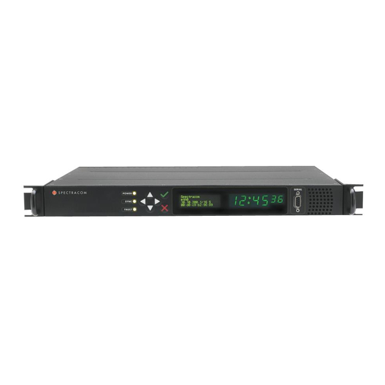
1.3 SecureSync Front Panel Figure 1-1: Front panel layout 1.3.1 Keypad and Information Display To simplify operation and to allow local access to SecureSync, a keypad and LCD information display are provided on the front panel of the unit. Among other things, the keypad and information display can be used to carry out basic net work configuration tasks, such as en-/disabling DHCP, or entering an IP address and subnet mask. - Page 21 1.3 SecureSync Front Panel accessible from the main “Home” menu. To navigate through the menus, use the arrow keys to highlight a selection and then press the ENTER button. The main menu options and their primary functions are as follows: Display : Used to configure the information display Clock : Displaying and setting of the current date and time System : Displaying version info, system halt and reboot, reset...
-
Page 22: Status Leds
1.3 SecureSync Front Panel 1.3.2 Status LEDs Three Status LEDs (see "Front panel layout" on page 4), located on the unit's front panel, indic ate SecureSync's current operating status: POWER : Green, always on while power is applied to the unit SYNC : Tri-color LED indicates the time data accuracy FAULT... -
Page 23: Unit Rear Panel
1.4 Unit Rear Panel LED Label Activity/Color Description No alarm conditions are currently active. FAULT Blinking A GNSS antenna alarm has been asserted and is currently active. orange A short or open circuit has been detected in the GNSS antenna cable. -
Page 24: Option Cards
1.5 Option Cards order shown above. However, not all cards can be installed in all slots. Your local Spectracom Sales Office will gladly assist you with the optimal option cards selection for your application. The DC Power port connector is only installed if your unit was ordered with a DC input power option. - Page 25 1.5 Option Cards Note: NEVER install an option card from the back of the unit, ALWAYS from the top. It is therefore necessary to remove the top cover of the main chassis (hous ing). Input and outputs can be categorized by: Communication direction : Input Output...
-
Page 26: Option Cards Overview
1.5 Option Cards Terminal block RJ-12/45 ST fiber optic To visually identify an option card installed in your unit, or to obtain an overview which option cards are available for SecureSync, see "Option Cards Overview" below. To obtain detailed information on a specific option card, using its ID number, see "Option Card Identification"... - Page 27 1.5 Option Cards Function Name used in Web UI Illustration Inputs Outputs Conn.'s Quad 1PPS out 1PPS Out, RS-485 1PPS, RS-485 Terminal (RS-485) (4x) block, 10-pin Quad 1PPS out 1PPS Out, Fiber 1PPS, F/O (4x) ST Fiber (fiber optic) optic (4x) 1in/3out 1PPS 1PPS/Frequency RS-...
- Page 28 1.5 Option Cards Function Name used in Web UI Illustration Inputs Outputs Conn.'s E1/T1 data, E1/T1 Out BNC 1.544/2.048 75 Ω MHz (1x) unbal. (3x) E1/T1 (2x) E1/T1 data, E1/T1 Out Terminal 1.544/2.048 Terminal 100/120 Ω MHz (1x) unbal. block, E1/T1 (2x) 10-pin Time Code Cards ASCII Time...
-
Page 29: Option Card Identification
1.5 Option Cards Function Name used in Web UI Illustration Inputs Outputs Conn.'s Networking Cards Gigabit Eth Gb Ethernet (3, OR (3, OR input) RJ-45 ernet output) (3x) 1Gb PTP: Gb PTP 1PPS (1x BNC), Master only SFP (1x) (1x), SFP (1x) Communication and Specialty Cards Event in, Broad... - Page 30 1.5 Option Cards comprised of the two center digits of your option card's Spectracom Part Num ber: 1204-0 0-0600. Figure 1-4: Option Card ID number The table lists all option cards available at the publication date of this documentation, sorted by their ID number .
- Page 31 1.5 Option Cards Card Card Name Name in UI See ... "Programmable Frequency Out [1204- Programmable Frequency Out Prog Freq Out, put module (Sine Wave) Sine 13, -2F, -30]" on page 371 CTCSS, Data Sync/Clock mod Simulcast "Simulcast (CTCSS/Data Clock) [1204- ule ("Simulcast") 14]"...
-
Page 32: Option Card Connectors
1.5 Option Cards Card Card Name Name in UI See ... "1PPS In/Out [1204-28, -2A]" on 1-in/3-out 1 PPS module (Fiber 1PPS In/Out, Optic) Fiber page 354 Quad 1 PPS output module 1PPS Out, Fiber "1PPS Out [1204-18, -19, -21, -2B]" on (Fiber Optic) page 349 Programmable Frequency Out... -
Page 33: The Securesync Web Ui
1.6 The SecureSync Web UI Connector Illustration Electr. Signals Timing signals RJ-12 RS-485 data clock, CTCSS frequency, 1 PPS, Alarm RJ-45 Gb-Ethernet PTP timing signal Ethernet The SecureSync Web UI SecureSync has an integrated web user interface (referred to as "Web UI" throughout this doc umentation) that can be accessed from a computer over a network connection, using a standard web browser. -
Page 34: The Interfaces Menu
HELP/MONITORING : Opens a drop-down menu for access to system help and inform ation on how to contact Spectracom for further help. (If the optional TimeKeeper license is installed, this button will open the TimeKeeper Monitoring menu. See also "Status Mon itoring with TimeKeeper"... -
Page 35: The Configuration Management Menu
1.6 The SecureSync Web UI External REFERENCES e.g., the GNSS reference input Detected OUTPUTS, such as 10 MHz and 1PPS Installed OPTION CARDS. Clicking on any of the line items will open a status screen, providing real-time information on the selected interface e.g., availability, performance data and events history. To configure settings for the selected interface, click the GEAR icons or buttons provided on most of the status screens. -
Page 36: The Tools Menu
1.6 The SecureSync Web UI On the left side, under NETWORK , the following standard setup screens can be found: Network Setup General Setup HTTPS Setup SSH Setup SNMP Setup NTP Setup PeerD Setup. Under OTHER , you can access non-network related screens: Authentication : Manage user accounts, Security Policy, LDAP Setup, RADIUS setup, Login Preference and Remote Servers. -
Page 37: Specifications
1.7 Specifications Specifications The specifications listed below apply to the SecureSync standard model, i.e. not including any option cards, and are based on “normal” operation, with SecureSync synchronized to valid Time and 1PPS input references (in the case of GNSS input, this is with the GNSS receiver oper ating in Stationary mode). ... -
Page 38: Gnss Receiver
1.7 Specifications Spectracom recommends: LITTELFUSE 0213002.MXP [Spectracom part number: F010R-0002-000 E FUSE,2A,SB,IEC SURGE,GLASS] Number : 2 (two) per unit SecureSync label on rear panel of unit: " AC POWER/F 2A T 250V (2) " LEGEND: F = Fuse 2A = Current Rating: 2 Ampères... -
Page 39: Serial Port (Front Panel)
NTP throughput : ETH0: 7000- 7200 NTP requests per second; ETH1- ETH3 (1204- 006- 0600 Gigabit Ethernet option card 1-3): 8800-9000 NTP requests per second. For additional inform ation, please contact Spectracom. Clients supported : The number of users supported depends on the class of network and the sub net mask for the network. -
Page 40: 10 Mhz Output
1.7 Specifications Table 1-6: 1PPS Output accuracies Holdover (constant temp. after 2 weeks of GPS Accuracy to UTC lock) Oscillator Type (1 sigma locked to GPS) After 4 hours After 24 hours Low-phase noise Rubid ±25 ns 0.2 μs 1μs Rubidium ±25 ns 0.2 μs 1μs... -
Page 41: 10 Mhz Output - Oscillator Phase Noise (Dbc/Hz)
1.7 Specifications Table 1-7: 10 MHz output — oscillator types and accuracies Oscillator Type Accuracy Low-phase noise Rubidium 1x10 typical 24-hour average locked to GPS 1x10 per day (5x10 per month) typical aging unlocked Rubidium 1x10 typical 24-hour average locked to GPS 1x10 per day (5x10 per month) typical aging unlocked... -
Page 42: Mechanical And Environmental Specifications
1.7 Specifications Oscillator Type @ 1Hz @ 10 Hz @ 100 Hz @ 1KHz @ 10 KHz Rubidium ˗80 ˗98 ˗120 ˗140 ˗140 Low-phase noise OCXO ˗100 ˗128 ˗148 ˗153 ˗155 OCXO ˗95 ˗123 ˗140 ˗145 ˗150 TCXO ˗110 ˗135 ˗140 1.7.8 Mechanical and Environmental Specifications Dimensions : Designed for EIA 19”... -
Page 43: Regulatory Compliance
1.8 Regulatory Compliance Vibration : ² ² Operating : 10-55 Hz @ 0.07 g /Hz; 55-500 Hz @ 1.0 g Storage : 10-55 Hz @ 0.15 g²/Hz; 55-500 Hz @ 2.0 g²/Hz MIL-STD-810F : 501.4, 502.4, 507.4, 500.4, 516.5, 514.5 Regulatory Compliance This product has been found to be in conformance with the following regulatory publications. This equipment has been tested and found to comply with the limits for a Class A digital device , pursuant to Part 15 of the FCC Rules . - Page 44 1.8 Regulatory Compliance may cause radio interference in which case the user may be required to take adequate measures. EMC, ICES-003 and AS/NZS CISPR 22: This Class (A) digital apparatus complies with Canadian ICES-003, Issue 4. This Class (A) digital apparatus complies with AS/NZS CISPR 22 for radiated and con ducted Emissions.
-
Page 45: Setup
SETUP T he following topics are included in this Chapter: 2.1 Overview 2.2 Unpacking and Inventory 2.3 Required Tools and Parts for Installation 2.4 Required GNSS Antenna Components 2.5 SAFETY 2.6 Mounting the Unit 2.7 Connecting Supply Power 2.8 Connecting the GNSS Input 2.9 Connecting Network Cables 2.10 Connecting Inputs and Outputs 2.11 Powering Up the Unit... -
Page 46: Overview
2.1 Overview Overview This section provides an outline of the steps that need to be performed prior to putting SecureSync into service. This includes: Installation : Hardware setup, mechanical installation, physical connections. Setup : Establish basic access to the unit, so as to allow the use of the web user interface ("Web UI"). -
Page 47: Unpacking And Inventory
Unpack the equipment and inspect it for damage. If any equipment has been damaged in transit, or you experience any problems during installation and configuration of your Spec tracom product, please contact Spectracom (see "Technical Support" on page 540.) Note: Retain all original packaging for use in return shipments if necessary. -
Page 48: Required Tools And Parts For Installation
Phillips screwdrivers to install the rack-mount ears, and to mount the unit in a 19"-rack Ethernet cables (see "Connecting Network Cables" on page 41) If you plan on using DC power Spectracom recommends an external ON/OFF switch. Required GNSS Antenna Components... -
Page 49: Safety
2.5 SAFETY SAFETY Caution: Do not ignore the Safety Instructions! 2.5.1 Safety: Symbols Used Table 2-1: Safety symbols used in this document, or on the product Symbol Signal word Definition Potentially dangerous situation which may lead to personal DANGER! injury or death! Follow the instructions closely. Potential equipment damage or destruction! CAUTION! Follow the instructions closely. - Page 50 — DO NOT OPEN EQUIPMENT, UNLESS AUTHORIZED: The interior of this equipment does not have any user serviceable parts. Contact Spectracom Technical Support if this equipment needs to be serviced. Do not open the equipment, except to retrofit option cards, or replacement of battery. Fol low Spectracom Safety Instructions, and observe all local electrical regulatory requirements.
-
Page 51: Safety: User Responsibilities
DANGER! — BATTERY: Replace the battery only with the same or equivalent type recommended by the manufacturer. Follow Spectracom Instructions — there is a danger of a new battery exploding if it is incorrectly installed. Discard used bat teries according to the manufacturer's instructions. -
Page 52: Safety: Other Tips
2.6 Mounting the Unit 2.5.4 SAFETY: Other Tips Keep these instructions at hand, near the place of use. Keep your workplace tidy. Apply technical common sense: If you suspect that it is unsafe to use the product, do the following: Disconnect the supply voltage from the unit. -
Page 53: Desktop Operation
2.7 Connecting Supply Power 2 each 1165-1000-0714 rack mounting brackets 2 each MP09-0003-0030 equipment rack handles 4 each H020-0832-0406 #8-32 flat head Phillips screws 6 each HM20R-04R7-0010 M4 flat head Phillips screws The following customer supplied items are also needed: 4 each #10-32 pan head rack mount screws 1 each #2 Phillips head screwdriver 1 each 3/32"... -
Page 54: Power Source Selection
2.7 Connecting Supply Power 2.7.1 Power Source Selection If both an AC, and a DC power source are connected to the unit, the following rules apply: If AC and DC power are both applied, AC power is used. If DC power is applied, but AC power is not, then DC power will be used. If AC and DC power are both present, but AC power is subsequently lost, SecureSync will automatically switch to using the DC power input. - Page 55 DC power plug for strain relief of the DC power input cable should be used when DC power is connected to SecureSync. Note: Spectracom recommends to use a dedicated DC power supply switch to energize/de-energize SecureSync externally. DC power connector pin-out:...
-
Page 56: Connecting The Gnss Input
2.8 Connecting the GNSS Input Mating DC Connector , circular, 3-pin, solder socket, 16AWG,13A,300V: Amphenol P/N DL3106A10SL-3S; (Spectracom part no. P240R-0032-002F) Cable Clamp , circular: Amphenol part no. 97-3057-1004(621); (Spectracom part no. Spectracom part no. MP06R-0004-0001) Pinout description, DC connector Pin B goes to the most positive DC voltage of the DC source. -
Page 57: Connecting Network Cables
2.9 Connecting Network Cables Problem alarm, causing the front panel “ Fault ” light to be blinking orange (the Antenna Problem alarm indicates an open or short exists in the antenna cable.) Unless there is an open or short in the antenna cable, the " Fault " light should stop flash ing orange once the GNSS antenna and coax cable are connected to the rear panel. -
Page 58: Connecting Inputs And Outputs
2.10 Connecting Inputs and Outputs (10.1.100.1 and 10.1.100.2 with a subnet value of 255.255.255.0 on both devices, for example). For more information on configuring static IP addresses, see "Assigning a Static IP Address" on page 45. Once the unit is up and running, verify that the link light on the Ethernet port is illu green minated. -
Page 59: Setting Up An Ip Address
2.12 Setting up an IP Address The time display will reset and then start incrementing the time. About 10 seconds after power-up, “Starting up SecureSync” will be displayed in the information display. After approximately 2 minutes, the information display will then show the current network set tings. -
Page 60: Dynamic Vs. Static Ip Address
Unless you are using DNS in conjunction with DHCP (with the client configured using SecureSync's hostname instead of IP address), Spectracom recommends to disable DHCP for SecureSync, and instead use a static IP address. Failure to do this can result in a loss of time synchronization, should the DHCP server assign a new IP address to SecureSync. -
Page 61: Assigning A Static Ip Address
2.12 Setting up an IP Address 2.12.2 Assigning a Static IP Address Spectracom recommends assigning a static IP address to SecureSync, even if the unit is con nected to a DHCP server. This can be accomplished in several ways: Via the keypad and information display on the front panel of the unit, see "Setting Up an IP Address via the Front Panel"... - Page 62 2.12 Setting up an IP Address Connect a pinned straight-thru standard DB9M to DB9F RS232 serial cable to a PC run ning PuTTY, Tera Term, or HyperTerminal, and to your SecureSync. Use the following protocol parameters: Bits per second: 9600 Data bits: 8 Parity: None Stop bits: 1...
-
Page 63: Setting Up An Ip Address Via The Front Panel
2.12 Setting up an IP Address Setting Up an IP Address via Ethernet Cable Note: You may use an Ethernet crossover cable, but you do not have to. Turn on the unit with NO cable plugged into the Ethernet port yet (Note: once you apply power, it may take up to two minutes for the system to fully boot). - Page 64 2.12 Setting up an IP Address Step-by-step instructions: First, disable DHCP: Press the key. ü Using the arrow key, select from the menu. Netv4 (To select a menu item, highlight it using the arrow keys, then press the ü key.) Select the Ethernet interface for which DHCP is to be disabled, such as eth0 Select...
-
Page 65: Setting Up A Static Ip Address Via A Dhcp Network
(on a computer connected to the SecureSync network). If the network supports DNS, the hostname may also be entered instead (the default hostname is "Spectracom"). The start screen of the SecureSync Web UI will be displayed. -
Page 66: Setting Up An Ip Address Via The Serial Port
2.12 Setting up an IP Address 2.12.2.4 Setting Up an IP Address via the Serial Port SecureSync's front panel serial port connector is a standard DB9 female connector. Com munication with the serial port can be performed using a PC with a terminal emulator program (such as PuTTY or TeraTerm) using a pinned straight-thru standard DB9M to DB9F serial cable. -
Page 67: Setting Up A Static Ip Address Via Ethernet Cable
2.12 Setting up an IP Address Note: If your SecureSync is configured with an Ethernet option card, use 0, 1, 2, 3 for eth0 – eth3. Remove the serial cable, connect SecureSync to the network, and access the Web UI, using the newly configured IP address. -
Page 68: Subnet Mask Values
2.13 Accessing the Web UI 2.12.3 Subnet Mask Values Table 2-2: Subnet mask values Network Bits Equivalent Netmask Network Bits Equivalent Netmask 255.255.255.252 255.255.192.0 255.255.255.248 255.255.128.0 255.255.255.240 255.255.0.0 255.255.255.224 255.254.0.0 255.255.255.192 255.252.0.0 255.255.255.128 255.248.0.0 255.255.255.0 255.240.0.0 255.255.254.0 255.224.0.0 255.255.252.0 255.192.0.0 255.255.248.0 255.128.0.0 255.255.240.0 255.0.0.0... - Page 69 "The Administrator Login Password" on page 232. Upon initial login, you will be asked to register your product. Spectracom recommends to register SecureSync, so as to receive software updates and services notices. See also "Product Registration" on page 258. Number of login attempts The number of failed login attempts for ssh is hard-set to (4) four.
-
Page 70: Configuring Network Settings
2.14 Configuring Network Settings 2.14 Configuring Network Settings Before configuring the network settings, you need to setup access to SecureSync web user inter face ("Web UI"). This can be done by assigning a static IP address, or using a DHCP address. For more information, see "Setting up an IP Address"... -
Page 71: General Network Settings
2.14 Configuring Network Settings SSH : This button takes you to the SSH Setup window. For details on setting up SSH, see "SSH" on page 69. HTTPS : This button takes you to the HTTPS Setup window. For details on setting up HTTPS, see "HTTPS"... -
Page 72: Network Ports
2.14 Configuring Network Settings Populate the fields: Hostname : This is the server’s identity on the network or IP address. Default Port : Unless you specify a specific Port to be used as Default Port, the fact ory default port eth0 will be used as the gateway (default gateway). The General Settings window also displays the IPv4 Address and default IPv4 Gateway. - Page 73 2.14 Configuring Network Settings Static IPv4 Address : This is the unique address assigned by the net work administrator. The default static IP address of the SecureSync unit is 10.10.201.1. In the format “ ” with no leading zer #.#.#.# oes or spaces, where each ‘...
-
Page 74: Network Services
2.14 Configuring Network Settings DNS Secondary : This is the secondary DNS address to be used for this port. Depending on how your DHCP server is configured, this is set automatically once DHCP is enabled, or your DHCP server may be configured NOT to set a DNS address. - Page 75 2.14 Configuring Network Settings view all configured Static Routes for all Ethernet Ports, or delete one or more Static Routes, click the TABLE icon in the top-right corner. a new Route, an existing Route for a specific Ethernet Port, locate view delete the Port listing you want to configure, and click the TABLE button next to it.
-
Page 76: Access Rules
2.14 Configuring Network Settings 2.14.5 Access Rules Network access rules restrict access to only those assigned networks or nodes defined. If no access rules are defined, access will be granted to all networks and nodes. Note: In order to configure Access Rules, you need ADMINISTRATOR rights. configure a new, or delete... -
Page 77: Https
2.14 Configuring Network Settings Click the Delete button next to an existing rule, if you want to delete 2.14.6 HTTPS HTTPS stands for HyperText Transfer Protocol over SSL (Secure Socket Layer). This TCP/IP pro tocol is used to transfer and display data securely by adding an encryption layer to protect the integrity and privacy of data traffic. -
Page 78: About Https
2.14 Configuring Network Settings The HTTPS Setup window has four tabs: Create Certificate Request : This menu utilizes the OpenSSL library to generate cer tificate Requests and self-signed certificates. Certificate Request : A holder for the certificate request generated under the Create Certificate Request tab. -
Page 79: Supported Certificate Format Types
If a Certificate Authority is not available, or while you are waiting for the certificate to be issued, you can use the default Spectracom self-signed SSL certificate that comes with the unit until it expires, or use your own self-signed certificate. The typical life span of a certificate (i.e., during which HTTPS is available for use) is about 10 years. - Page 80 2.14 Configuring Network Settings Fill in the available fields: Create Self-Signed Certificate : Caution: Spectracom recommends to check this box (if needed) after you have filled out the form completely, clicking Submit. This before will prevent inadvertent submission. This checkbox serves as a security feature : Check this box before clicking Submit,...
- Page 81 It is recommended that you consult your Certificate Authority for the required fields in an X 509-certificate request. Spectracom recommends all fields be filled out and match the information given to your Certificate Authority. For example, use all abbreviations, spellings, URLs, and company departments recognized by the Certificate Authority.
-
Page 82: Requesting An Https Certificate
2.14 Configuring Network Settings When switching between tabs within the HTTPS Setup window, the information you have entered will be retained. If you exit the window before clicking Sub HTTPS Setup mit, the information will be lost. 2.14.6.5 Requesting an HTTPS Certificate Before requesting an HTTPS Certificate from a third-party Certificate Authority, you need to cre ate a Certificate Request : Navigate to MANAGEMENT >... - Page 83 It will be displayed under the Certificate Request tab. You may use your self-signed certificate (or the default Spectracom self-signed certificate that comes with the unit) while waiting for the HTTPS certificate from the Certificate Authority, or – if a Certificate Authority is not available –...
-
Page 84: Uploading An X.509 Pem Certificate Text
2.14 Configuring Network Settings 2.14.6.6 Uploading an X.509 PEM Certificate Text Many certificate authorities simply issue a certificate in the form of a plain text file. If your cer tificate was provided in this manner, and the certificate is in the X.509 PEM format, follow the procedure below to upload the certificate text by copying and pasting it into the Web UI. -
Page 85: Ssh
2.14 Configuring Network Settings Note: For more information about certificate formats, see "Supported Certificate Format Types" on page 63. To upload an HTTPS certificate file to SecureSync: Store the Public Keys File provided to you by the Certificate Authority in a location accessible from the computer on which you are running the Web UI. - Page 86 2.14 Configuring Network Settings Note: Only SSH2 is supported due to vulnerabilities in the SSH1 protocol. The SSH tools supported by SecureSync are: SSH : Secure Shell SCP : Secure Copy SFTP : Secure File Transfer Protocol SecureSync implements the server components of SSH, SCP, and SFTP. www.openssh.org For more information on OpenSSH, please refer to To configure SSH:...
- Page 87 2.14 Configuring Network Settings Note: Should you exit the SSH Setup window (by clicking in the top right corner of the window, or by clicking anywhere outside of the window), while filling out the Certificate Request Parameters form before clicking Submit , any information you entered will be lost.
- Page 88 2.14 Configuring Network Settings SSH using public/private key authentication is the most secure authenticating method for SSH, SCP or SFTP sessions. You are required to create private and public key pairs on your workstation or within a private area in your network account. These keys may be RSA or DSA and may be any key bit length as supported by the SSH client tool.
- Page 89 2.14 Configuring Network Settings take 10 minutes or more to generate. DSA keys size support is limited to 1024 bits. The key type ED25519 supports 256 bits. Check the Regenerate All Keys box. Click Submit . The new values will be saved. Note: Changing the values and submitting them in this manner DOES NOT gen erate new host public/private key pairs.
- Page 90 2.14 Configuring Network Settings To access the SSH setup screen, navigate to MANAGEMENT > NETWORK: SSH Setup . The window will open to the Host Keys tab by default. Should you want to change the key length of any host key, enter the desired length in the text field corresponding to the length you wish to change.
- Page 91 2.14 Configuring Network Settings Note: If a key size is undefined, the default key bit length size used is 2048. A key with a zero length or blank key size field will not be created. When you delete a host key and recreate a new one, SSH client sessions will warn you that the host key has changed for this particular IP address.
- Page 92 2.14 Configuring Network Settings Edit the file as desired. authorized_keys Click the Submit button or Apply button. The file is to be formatted such that the key is followed by an optional comment, with only one key per line. The file format, line terminations, and other EOL or EOF characters should cor respond to UNIX conventions, not Windows.
- Page 93 Creating an SSH session using Public Key with Passphrase Authentication for the admin account You must first provide the secure Spectracom product a RSA public key found typically in the OpenSSH id_rsa.pub file. Then you may attempt to create an SSH session.
-
Page 94: Snmp
Recommended SSH Client Tools Spectracom does not make any recommendations for specific SSH clients, SCP clients, or SFTP client tools. However, there are many SSH based tools available to the user at low cost or free. Two good, free examples of SSH tool suites are the command line based tool OpenSSH run ning on a Linux or OpenBSD x86 platform and the SSH tool suite PuTTY. - Page 95 2.14 Configuring Network Settings The SNMP screen is divided into 3 panels: The Main panel , which is subdivided into 3 displays: SNMP V1/V2 : This panel allows configuration of SNMP v1 and v2c com munities (used to restrict or allow access to SNMP). This tab allows the con figurations for SNMP v1 and v2c, including the protocols allowed, permissions and Community names as well as the ability to permit or deny access to portions of the network.
- Page 96 2.14 Configuring Network Settings Contact Information —The email to contact for service. This is editable in the SNMP Status panel (see "Configuring the SNMP Status" below). Location —The system location. This is editable in the SNMP Status panel (see "Configuring the SNMP Status" below). Description —...
- Page 97 Click Submit , or cancel by clicking the X -icon in the top-right corner. Accessing the SNMP Support MIB Files Spectracom’s private enterprise MIB files can be extracted via File Transfer Protocol (FTP) from SecureSync, using an FTP client such as FileZilla or any other shareware/freeware FTP pro gram.
-
Page 98: Snmp V1/V2C
2.14 Configuring Network Settings Spectracom’s private enterprise MIB files can be requested and obtained from the Spec techsupport@spectracom.com tracom Customer Service department via email at techsupport@spectracom.com Note: By default, is the address in the sysContact field of the SNMP Status panel of the SNMP Setup page. - Page 99 2.14 Configuring Network Settings If no value is entered in the IPv4 and/or IPv6 field, SecureSync uses the system default address. SNMP Community names should be between 4 and 32 characters in length. Permissions may be Read Only or Read/Write The Version field provides a choice of V1 or V2c.
-
Page 100: Snmp V3
2.14 Configuring Network Settings 2.14.8.2 SNMP V3 SNMP V3 utilizes a user-based security model which, among other things, offer enhanced secur ity over SNMP V1 and V2. Creating Users Navigate to MANAGEMENT > NETWORK: SNMP Setup . In the SNMP V3 panel, click the PLUS icon in the top-right corner. The SNMP V3 Settings window will display. -
Page 101: Snmp Traps
2.14 Configuring Network Settings Editing and Deleting Users To edit or delete a user you have created: Navigate to MANAGEMENT > NETWORK: SNMP Setup . Click the row of the SNMP V3 panel that displays the community you wish to edit or delete. - Page 102 2.14 Configuring Network Settings Navigate to MANAGEMENT > NETWORK: SNMP Setup . In the SNMP Traps panel, click the PLUS icon in the top-right corner. The SNMP Traps Settings window will display: Enter the required information in the fields provided. (Note that the options will vary con textually according to your Version The Version field provides a choice between...
-
Page 103: System Time Message
MIBs reside under the enterprise identifier @18837.3. For detailed descriptions of the objects and traps supported by the SecureSync, please refer to the Spectracom SecureSync MIB files. See "Accessing the SNMP Support MIB Files" on page 81. 2.14.9 System Time Message The System Time Message is a feature used for special applications that require a once-per- second time message to be sent out by SecureSync via multicast. -
Page 104: System Time Message Format
2.14 Configuring Network Settings In the Network Services panel, enable System Time Message . 2.14.9.1 System Time Message Format This message contains the time when the next 1PPS discrete will occur. It is sent once per second prior to the 1PPS discrete. Table 2-4: System Time Message format Word... -
Page 105: Configuring Ntp
2.15 Configuring NTP Table 2-5: System Time Message field descriptions Data Data Description Range Resolution Units Name Message UID of the message; programmable Unsigned 32 bit integer Message Total message size in bytes Unsigned 32 bit Bytes Size integer Seconds Seconds since epoch (00:00:00 Jan 1, Unsigned 32 bit Seconds... -
Page 106: Checklist Ntp Configuration
2.15 Configuring NTP 2.15.1 Checklist NTP Configuration The following is a list of configuration settings you may want to consider as you setup your NTP Service. (Not all items may apply to your application, or there may be other considerations not included in this list.) Did you setup your NTP Service and have it use the right Reference(s) ? See "NTP Reference Configuration"... - Page 107 2.15 Configuring NTP Note: The panels will be disabled if you applied the optional TimeKeeper license, and enabled TimeKeeper ( > MONITORING TimeKeeper Service The NTP Servers and Peers panels … are located on the right-hand side of the NTP screen: NTP Servers : In this display you can view the NTP Servers that SecureSync detects in your network.
- Page 108 2.15 Configuring NTP The INFO icon opens a window showing the maximum per second traffic rate from each. The graphs maybe saved and downloaded (> ARROW icon), or deleted (> TRASH CAN icon). Note that this data is currently only displayed for NTP, and not for TimeKeeper NTP. The Actions panel …...
-
Page 109: Dis-/Enabling Ntp
SecureSync Web UI. [Default =OFF] See "NTP Expert Mode" on page 127. Note: Spectracom Tech Support does not support the editing of the NTP configuration files in Expert Mode. For additional information on editing http://www.ntp.org the NTP.conf file, please refer to... -
Page 110: Viewing Ntp Clients
2.15 Configuring NTP A notification window will confirm the status change. In the NTP Services panel, set the ON/OFF toggle switch to ON again. Changes made will now take effect and NTP operation will be restored shortly after this oper ation is performed. -
Page 111: Restoring The Default Ntp Configuration
2.15 Configuring NTP You can search any of the fields for specific information in the Search field at the top of the window. A limit of 10 entries will appear on the screen at any one time. If you have more than 10 clients, you can move through the table using the First , Previous , Next and Last navigation buttons at the bottom of the screen. - Page 112 2.15 Configuring NTP Note that the System Time affects not only NTP output, but also all other aspects of time man agement e.g., time distributed via channels other than NTP, logging, and time displayed on the unit front panel and in the Web UI. If SecureSync is operated as a Stratum 2 server, i.e.
-
Page 113: Ntp Reference Configuration
2.15 Configuring NTP 2.15.7 NTP Reference Configuration SecureSync's NTP Service needs to be setup such that it utilizes the time source ("input ref erence") you want it to use. There are two options for an NTP Server to derive its time from: The NTP Service uses SecureSync's System Time, i.e. -
Page 114: Configuring "Ntp Stratum Synchronization
2.15 Configuring NTP use the System Time as a reference to NTP, since this provides NTP with the most accurate ref erences. This mode is called Stratum 1 operation, since SecureSync operates as a Stratum 1 NTP server. To configure Stratum 1 operation for SecureSync: Navigate to MANAGEMENT >... -
Page 115: Ntp Servers And Peers
Enable Stratum 1 Operation When the checkbox Prefer Stratum 1 is unchecked, the input from a different NTP Server or Peer will normally be used at all times. Spectracom, however, recommends to check this box, thus allowing the NTP Ser vice to use SecureSync's System Time during Holdover , i.e. if the external NTP ref erence has become unavailable. - Page 116 2.15 Configuring NTP other higher stratum servers. If a peer loses all reference clocks or fails, the other peers continue to provide time to other clients on the network. NTP Servers at the same Stratum level If SecureSync is configured to obtain time from other NTP Servers at the same Stratum level (i.e., NTP Peers) but is currently using a different input reference as its selected reference, SecureSync will report to the network (via the NTP time stamps) that it is a Stratum 1 time server.
-
Page 117: The Ntp Servers And Ntp Peers Panels
2.15 Configuring NTP 2.15.8.1 The NTP Servers and NTP Peers Panels The NTP Servers and NTP Peers panels display which servers in the network are set up at higher or equal Stratums (Servers or Peers, respectively), and their configurations. These panels are also used to add, configure, or remove NTP Servers and Peers. -
Page 118: Ntp Servers: Adding, Configuring, Removing
2.15 Configuring NTP ATC : ASCII time code reference USER : User provided time LOCL : Local reference (synced to itself) INIT : NTP on server/peer is initializing STEP : NTP on server/peer is performing initial synchronization step and restart AUTH STATUS : Indicates if the selected reference is using MD5 authentication. - Page 119 2.15 Configuring NTP The NTP Servers window opens. Should the list be empty, no servers have been added yet. In the event that added servers are not displayed in the NTP Setup screen/NTP Serv ers panel, they could not be resolved. Verify the IP address. Note that System servers can not be edited or deleted.
-
Page 120: Ntp Peers: Adding, Configuring, Removing
2.15 Configuring NTP Note: When you configure NTP Autokey, you must first disable the NTP service in the NTP Services panel, and then re-enable it after the Autokey configuration is completed. Enable Burst : This tells NTP to send a burst to the remote server when the server is reachable. - Page 121 2.15 Configuring NTP Enter the required information into the fields: Host : The IP address for the server to be used as host. Min Poll Interval : Select a value from the drop down (the default is 3 (8s). Max Poll Interval : Select a value from the drop down (the default is 3 (8s). For both NTP Peers, and NTP Servers the Minimum and Maximum Poll rate for NTP packets can be configured.
-
Page 122: Ntp Authentication
2.15 Configuring NTP Note: When you configure NTP Autokey, you must first disable the NTP service in the NTP Services panel, then re- enable it after Autokey configuration is completed. Mark as Preferred : Check this box to prefer this NTP Peer over other NTP Peers ("NTP Peer Preference"). - Page 123 2.15 Configuring NTP NTP Autokey: IFF Autokey Support The IFF Autokey Support is demonstrated in the figure below. The IFF identity scheme is used with Multiple Stratum NTP Time Servers. The example below shows 3 Stratum layers. Stratum 1 NTP Servers are close to the physical time references. All Stratum 1 servers can be Trusted Hosts.
- Page 124 2.15 Configuring NTP Figure 2-2: IFF Autokey configuration example Configuring NTP Autokey Note: As of spring 2016, NTP Autokey is currently not supported; for more inform http://bugs.ntp.org/show_bug.cgi?id=3005 ation, see CHAPTER • SecureSync User Reference Guide Rev. 23...
- Page 125 2.15 Configuring NTP Note: When you configure NTP Autokey, you must disable the NTP Service first, and then re- enable it after Autokey configuration is completed. See "Dis- /En abling NTP" on page 93. To configure NTP Autokey: Navigate to MANAGEMENT > NETWORK: NTP Setup . In the NTP Services panel, click the GEAR icon in the top-right corner.
- Page 126 2.15 Configuring NTP To designate a SecureSync as Trusted , click the Submit button. This will generate a new Groupkey . To designate a SecureSync as a Client or a Server , paste the generated Groupkey into the Groupkey box, and click the Submit button. Configuring a Stratum-1 Server as Trusted Host To configure an NTP Stratum-1 Server as Trusted Host with IFF Group/Client key: Define the Hostname of all NTP servers before proceeding.
- Page 127 2.15 Configuring NTP Creating a Stratum-1 Group Member Server To configure an NTP Stratum-1 Server, which is a Group Member, using a Client key: Define the Hostname, making sure it is not the same as the trusted root server. See "NTP Servers: Adding, Configuring, Removing"...
-
Page 128: Ntp: Symmetric Keys (Md5)
2.15 Configuring NTP For all NTP Stratum-2 servers and higher stratum numbers, under the Stratum-1 tab in the Edit NTP Services window configure the NTP Stratum-1 references: Disable Enable Stratum 1 Operation. Disable Enable Stratum 1 1PPS. In the NTP Servers panel of the main window, add an NTP server and enable the Autokey option box. - Page 129 2.15 Configuring NTP EDIT an existing key pair, click the corresponding Change button, and pro ceed to Step 4. DELETE a key pair, click the corresponding Delete button, and click OK in the dialog box to confirm and complete the procedure. The NTP Symmetric Key window will display: Fill in, or edit the fields: Trusted (checkbox)—Check this box to use MD5 authentication with trusted key ID.
-
Page 130: Ntp Access Restrictions
2.15 Configuring NTP The key(s) you have set up will now appear as options in the Symmetric Key field in both the NTP Server screen, and the NTP Peer screen. NOTES: Duplicate key IDs are not permitted. NTP requests received by that do not contain an authen ticator containing a valid Key ID and MD5 message digest pair will be responded to, but no authentication will be performed. - Page 131 2.15 Configuring NTP manipulation of a time server. To configure NTP Access Restrictions: Navigate to MANAGEMENT > NETWORK: NTP Setup . In the Actions panel, click Access Restrictions : The NTP Access Restrictions Status window will display: EDIT an access restriction, click the PLUS icon or the Change button, respectively, and proceed to Step 4.
-
Page 132: Enabling/Disabling Ntp Broadcasting
2.15 Configuring NTP Fill in the fields: Restriction Type —Choose either Allow or Deny. If you select “Deny”, the configured portion of the network will not have NTP access to SecureSync, but the rest of the network will have access to SecureSync. -
Page 133: Ntp Over Anycast
Associate one of its network ports to an Anycast IP address, and Remove itself as an available time source if its reference is lost or degraded, and vice versa. Spectracom Technology Brief To learn more about NTP over Anycast, see also the respective (PDF) CHAPTER •... -
Page 134: Configuring Ntp Over Anycast (General Settings)
2.15 Configuring NTP Please note that SecureSync utilizes the OSPF (Open Shortest Path First) and BGP (Border Gate way Protocol). O S P F P r o t o c o l E X A M P L E : If an active SecureSync NTP server has removed itself as an available time source from the Anycast- capable network, the OSPF router will send a request for replacement to the next nearest NTP server, serving under the same NTP over Anycast address. -
Page 135: Configuring Ntp Over Anycast (Ospf Ipv4)
2.15 Configuring NTP In the Actions Panel , click NTP over Anycast . In the NTP Anycast window, select the General tab. On the General tab, select the IP Version you will be running Anycast service for. The options are IPv4, IPv6, or both. Configure the Anycast Address to be used. -
Page 136: Configuring Ntp Over Anycast (Ospf Ipv6)
2.15 Configuring NTP Select the port address to associate the Anycast service with (because there may be mul tiple addresses on a single port), and click Submit . If no addresses appear, an IP address must be added to the port (see "Network Ports" on page 56). Next, specify the maximum (Time Figure of Merit), and the TFOM Setting... -
Page 137: Configuring Ntp Over Anycast (Bgp)
2.15 Configuring NTP Click Submit. Select the port address to associate the Anycast service with (because there may be mul tiple addresses on a single port), and click Submit. If no addresses appear, an IP address must be added to the port (see "Network Ports" on page 56). Next, specify the maximum TFOM Setting (Time Figure of Merit), and the... -
Page 138: Configuring Anycast Via Ntp Expert Mode
2.15 Configuring NTP Input the neighbor's AS number. Click Submit . Select the port address to associate the Anycast service with (because there may be mul tiple addresses on a single port), and click Submit. If no addresses appear, an IP address must be added to the port (see "Network Ports"... - Page 139 2.15 Configuring NTP Once it is enabled, click NTP Anycast in the Actions Panel . The Expert mode window will appear, with a separate tab for each of the three configuration files. To enable OSPF IPv4 Anycast, check Enable under the OSPF tab. To enable OSPF IPv6 Anycast, check Enable under the OSPF6 tab.
- Page 140 2.15 Configuring NTP ip address 10.10.14.1/32 ipv6 address 2000:10:10::1/64 ***************************************************** Example zebra.conf file showing the default file with no addresses configured: (Interface eth0 line, with no lines following it because no addresses are configured on the port) ***************************************************** interface eth0 interface lo ***************************************************** Example ospfd.conf file:...
-
Page 141: Testing Ntp Over Anycast
***************************************************** 2.15.12.6 Testing NTP over Anycast Note: A detailed Anycast test procedure is available from Spectracom upon techpubs@spectracom.com request. Please contact 2.15.13 NTP Orphan Mode The NTP Orphan Mode allows SecureSync to remain a valid time server to its NTP clients even if all its input references have become invalid and the Holdover period has expired. -
Page 142: Host Disciplining
2.15 Configuring NTP Click the Orphan Mode tab, and select an NTP Stratum other than 15 . This will be the Stratum level SecureSync will transition to in the event its input references become invalid. Click Submit. SecureSync will automatically stop and re-start the NTP Service. Note: Per NTP protocol definition, for an NTP Orphan Mode Timing Network... -
Page 143: Enabling Host Disciplining
2.15 Configuring NTP OFF [ default setting]: When OFF, NTP synchronization is not disciplining the oscillator, only a time transfer is made in regular intervals to manually correct the system time. While disabled Host Disciplining does not offer the benefit of a disciplined oscillator when transitioning into or out of holdover, SecureSync on the other hand will not be sus ceptible to disciplining errors caused by network traffic or NTP-related issues. - Page 144 When Expert Mode is enabled, the user has direct access to the file. NTP.conf Spectracom Tech Support does not support the editing of the NTP con Caution: figuration files while in the Expert Mode. For additional information on editing http://www.ntp.org/...
- Page 145 127.127.22.0 stratum 0 peer 10.10.128.35 minpoll 3 maxpoll 3 autokey keysdir /etc/ntp/keys/ crypto pw admin123 randfile /dev/urandom driftfile /etc/ntp/ntp.drift logfile /home/spectracom/log/ntp.log statsdir /home/spectracom/log/ntpstats/ statistics loopstats peerstats clockstats filegen loopstats file loopstats type day enable filegen peerstats file peerstats type day enable...
-
Page 146: Spectracom Technical Support For Ntp
NTP Expert Mode is disabled. 2.15.16 Spectracom Technical Support for NTP Spectracom does not provide technical assistance for configuring and installing NTP on Unix- www.ntp.org based applications. Please refer to for NTP information and FAQs. Another help news://comp.protocols.time.ntp... -
Page 147: Configuring Input References
2.16 Configuring Input References 2.16 Configuring Input References Depending on the type of input reference, some of its settings may be user-editable. To access these settings for a given input reference, choose one of the two methods described below. The illustrations shown below are examples. The windows displayed in Note: your Web UI may look differently. -
Page 148: The Outputs Screen
2.17 Configuring Outputs Under INTERFACES: OUTPUTS , click the desired output. The Status window for the specific reference you selected will be displayed. Click the Edit button in the bottom-left corner. The settings window for the chosen output will be displayed. Edit the field(s) as desired. Editing output settings, method 2: In the INTERFACES: OUTPUTS drop-down menu, click OUTPUTS... -
Page 149: The 1Pps And 10 Mhz Outputs
2.17 Configuring Outputs While System Status and logged Events are displayed on the left, the Outputs panel on the right lists all the outputs detected. If you hover with your mouse pointer over any of the connectors shown in the rear panel illustration, a tooltip will be displayed, indicating the type of output.. - Page 150 2.17 Configuring Outputs unless in Host Disciplining mode). If no external 1PPS input references that can be used for dis ciplining are present, the oscillator will be in Freerun mode. The selected 1PPS input reference (as configured with the Reference Input Priority table) is used to align SecureSync’s on-time point.
-
Page 151: Configuring A 1Pps Output
2.17 Configuring Outputs 2.17.2.1 Configuring a 1PPS Output To configure a 1PPS output: Navigate to INTERFACES > OUTPUTS ., or to INTERFACES > OPTION CARDS (white on orange). In the panel on the right, click the GEAR button next to the 1PPS Output you want to edit. The 1PPS Output Edit window will display, allowing the following items to be configured: Signature Control : Determines when the output is enabled. -
Page 152: Configuring Optional Outputs
2.17 Configuring Outputs The 10 MHz edit window will display. Choose a value from the Signature Control field drop-down list to determine what SecureSync shall do with the output signal in the event its input reference is lost. For more information, see "Signature Control" below. Click Submit. -
Page 153: Configuring Signature Control For An Output
2.17 Configuring Outputs Output Enabled in Holdover —The output is present unless SecureSync is not syn chronized to its references (SecureSync is in Holdover mode). III. Output Disabled in Holdover —The 1PPS output is present unless the SecureSync ref erences are considered not qualified and invalid (the output is NOT present while SecureSync is in Holdover mode.) Output Always Disabled —The output is never present, even if SecureSync references are present and valid. - Page 154 2.17 Configuring Outputs To learn more about the different settings, see the previous topic "Signature Control" on page 136. CHAPTER • SecureSync User Reference Guide Rev. 23...
-
Page 155: Managing Time
MANAGING TIME In this document, the notion of Managing Time refers not only to the concept of SecureSync's System Time, but also to reference con figuration, as well as distribution of time and frequency. T he following topics are included in this Chapter: 3.1 The Time Management Screen 3.2 System Time 3.3 Managing References... -
Page 156: The Time Management Screen
3.1 The Time Management Screen The Time Management Screen The Time Management screen is the point of entry for all System Time -related settings that are user-configurable. To access the Time Management screen: Navigate to MANAGEMENT > OTHER: Time Management . The Time Management screen opens. -
Page 157: System Time
3.2 System Time SecureSync’s time keeping. It is also possible to enter the exact day and time when the leap second is to be applied, and to delete a leap second. See also: "Leap Seconds" on page 149 Local Clocks panel You can create multiple different Local Clocks, as needed. -
Page 158: System Time
3.2 System Time Note: User hand-set times can only be set in UTC (not Local time). 3.2.1 System Time Several System Time parameters can be customized: The System Timescale can be changed. A user-defined time can be setup for e.g., for simulation purposes, or if no external ref erence is available. -
Page 159: Timescales
3.2 System Time Note that UTC is not a time zone, but a time standard, i.e. it is not used anywhere in the world as the official local time, whereas GMT (Greenwich Mean Time) is a time zone that is used in several European and African countries as the official local time. -
Page 160: Manually Setting The Time
3.2 System Time Some of the inputs may not necessarily provide time to SecureSync in the same timescale selec ted in the System Time’s timescale field. These inputs have internal conversions that allow the timescale for the inputs to also be independently defined, so that they don’t have to be provided in the same timescale. - Page 161 3.2 System Time but the system has to be setup and tested. In such cases, the System Time can be hand-set, and then used as a User [x] -set System Time. For more information on when to use this functionality, see "The "User/User" Reference" on page 161.
-
Page 162: Using Battery Backed Time On Startup
Set Year Only : Some legacy time formats (e.g., IRIG) do not support years. Check ing this box will open a data entry field to manually set the year. Spectracom recommends not to utilize this feature, unless the IRIG format you are using does provide a YEAR field. - Page 163 3.2 System Time soon an external reference will become available, its time will take precedence over the battery backed time: The System Clock will adjust the System Time for any time difference. The Battery Backed Time is also referred to as the time maintained by the Note: integrated Real-Time Clock...
-
Page 164: Timescale Offset(S)
3.2 System Time The Edit System Time window will display. Select the checkbox Synchronize to Battery Backed Time on Startup : Click the Submit button. 3.2.2 Timescale Offset(s) Timescale offsets account for fixed differences between timescales, in seconds. Timescale offsets may change because of leap seconds, see "Leap Seconds"... -
Page 165: Leap Seconds
3.2 System Time Note: Since the GPS Offset and the TAI Offset have a fixed relationship, only the GPS Offset can be set. If only the TAI offset is known, subtract 19 from it, in order to obtain the GPS offset. Note that the data stream of GPS and several other external references includes information about a pending Leap Second, and as such automatically corrects for a Leap Second. -
Page 166: Leap Second Alert Notification
3.2 System Time arbitrary number of months in advance. Input references other than GNSS : Some of the other available input references (e.g., IRIG, ASCII, NTP) can also contain pending Leap Second notification in their data streams (see chapter below). Manual user input : SecureSync can be manually configured with the date/time of the next pending Leap Second. -
Page 167: Configuring A Leap Second
3.2 System Time Sequence of seconds output when adding a second ("positive Leap Second"): 56, 57, 58, 59, 60 , 0, 1, 2, 3 … Sequence of seconds output when subtracting a second ("negative Leap Second"): 56, 57, 58, 0 , 1, 2, 3, 4 … 3.2.3.4 Configuring a Leap Second To manually correct the System Time for a leap second:... -
Page 168: Local Clock(S), Dst
3.2 System Time Note: The Delete button in the Edit Leap Second window will only be visible if a leap second has been set beforehand. 3.2.4 Local Clock(s), DST The Local Clock feature allows for maintaining one or several local times. These times will reflect a time offset, thereby accounting for Time Zone, and DST (Daylight Savings Time) cor rection. - Page 169 3.2 System Time Note: Acceptable characters for the name include: A-Z, a-z, 0-9, (- +_) and space. In the UTC Offset field, choose a UTC Offset from the drop-down list. All of the UTC Offset drop-down selections are configured as UTC plus or minus a set number of hours.
-
Page 170: Dst Examples
3.2 System Time Note: If a pre-configured rule DST rule happens to be changed in the future (like the change to the US DST rule in 2006), this option allows the DST rules to be edited without the need to perform a soft ware upgrade for a new DST rule to be defined. -
Page 171: Dst And Utc, Gmt
3.3 Managing References E x a m p l e To create a Local Clock for a SecureSync installed in the Eastern Time Zone of the US, and desiring the Local Clock to automatically adjust for DST (using the post 2006 DST rules for the US). MANAGEMENT >... - Page 172 3.3 Managing References In order for SecureSync to declare synchronization, it needs both a valid 1PPS , and Time ref erence. The concept of Reference Priority allows the ranking of multiple references for redundancy. This allows SecureSync to gracefully fall back upon a lower ranking 1PPS or Time reference without transitioning into Holdover, in case a reference becomes unavailable or invalid.
-
Page 173: Configuring Input Reference Priorities
3.3 Managing References Title Reference NTP input User Host (time is manually set by the user) HAVEQUICK HAVEQUICK input The number displayed indicates the number of feature inputs of that type presently installed in the SecureSync– starting with “0” representing the first feature input. For example: IRIG 0 = 1 IRIG input instance Frequency 1 = 2nd frequency input instance... - Page 174 3.3 Managing References On the HOME screen, click the GEAR icon in the Reference Status panel: The Configure Reference Priorities screen will display. The Reference Priority screen is divided into 3 areas: The Actions panel, which provides a single action: Restore Factory Defaults The Configure Reference Priorities panel, which displays the priority of SecureSync’s references in a table form.
- Page 175 3.3 Managing References To add a new entry to the Reference Status table: Navigate to the Configure Reference Priorities screen via MANAGEMENT > OTHER: Reference Priority . Click the PLUS icon in the top right-hand corner of the Configure Reference Priorities table.
-
Page 176: The "Local System" Reference
3.3 Managing References Click Submit. Resetting Reference Priorities to Factory Defaults To reset all references in the Reference Priority table to their factory default priorities: Navigate to the Configure Reference Priorities screen via MANAGEMENT > OTHER: Reference Priority menu. In the Actions panel, click the Restore Factory Defaults button. 3.3.1.2 The "Local System"... -
Page 177: The "User/User" Reference
3.3 Managing References Vice versa, when the 1PPS reference is configured as Local System , SecureSync's built-in oscillator is considered a valid reference, as long as the external Time reference is valid. Use case "Local System Time" The Local System reference when used for allows SecureSync to operate using its current Time Time-of-Day (ToD) for Time, while synchronized to an external 1PPS reference. - Page 178 3.3 Managing References To utilize a backup reference as soon as possible after a power cycle or reboot of SecureSync, while waiting for the primary reference (e.g., GNSS) to become valid. To this end, in the Edit System Time window, the checkbox Synchronize to Battery Backed Time on Startup must be checked, AND the User/User reference is assigned a reference priority number other than "1".
-
Page 179: Reference Priorities: Examples
3.3 Managing References See "Manually Setting the Time" on page 144. Using the "User" Reference with Other References If the User/User reference is used in conjunction with other, external references (such as GNSS or IRIG), the System Time should be set as accurately as possible: Otherwise, the large time correction that needs to be bridged when switching from a lost ref erence to a valid reference, or from a valid reference to a higher-priority reference that has become available again, will cause NTP to exit synchronization. - Page 180 3.3 Managing References Move the reference which has “NTP” in the Time column and “NTP” in the 1PPS column to the second place in the table, with a Priority value of 2. Click the Enabled checkbox. For all other references, uncheck the Enabled checkbox, so that they are all disabled. default Since both of these references are references, no additional references need to be...
- Page 181 3.3 Managing References column to the top of the table, with a Priority value of 1. Click the Enabled checkbox. For all other references, uncheck the Enabled checkbox, so that they are all disabled. backup If the objective is to use a manually set time as a to other references (such as GNSS or IRIG): Move the "User/User"...
-
Page 182: The Gnss Reference
3.3 Managing References In the Time field, select “Local System”. In the PPS field, select “GPS”. Check the Enabled checkbox. Confirm that the first reference in the Reference Priority table has “Local System” as the Time input and "GNSS" as the 1PPS input. After a power cycle or reboot, as soon as GNSS is declared valid, the System Time will automatically be used as-is, with no manual intervention required. -
Page 183: Reviewing The Gnss Reference Status
3.3 Managing References ® Trimble Resolution-T ® Trimble Res–SMT GG ® u-blox M8T 3.3.2.1 Reviewing the GNSS Reference Status To view the current status of your GNSS reference: Navigate to INTERFACES > REFERENCES: GNSS Reference . Click the INFO button next to GNSS 0 . The GNSS 0 status window will display; it con tains two tabs, explained in detail below: Main [= default], and Satellite Data . - Page 184 3.3 Managing References Under the Main tab, the following information will display: Note: Detailed information on the different parameters can be found in the sub sequent GNSS topics. Manufacturer/Model : The manufacturer and/or model of the GNSS receiver in your SecureSync unit.
- Page 185 3.3 Managing References With your mouse pointer, hover over a bar graph to display tool tip information about satellite constellation (if equipped for Multi-GNSS reception), satellite number, and sig nal strength. Letter Symbol GNSS Constellation GLONASS Galileo QZSS BeiDou IRNSS The "Satellite Data"...
-
Page 186: Determining Your Gnss Receiver Model
In the System Configuration panel, locate the line item GNSS Receiver : GNSS Receiver Models Spectracom strives to equip SecureSync with current technology. Depending on the production date of your SecureSync unit, one of the following GNSS receiver models will be installed in your unit (if any): ®... - Page 187 3.3 Managing References Production dates: up to 2014 Constellations: GPS Other characteristics: A-GPS option: No Resurvey: Automatic, when moved. Trimble Res-SMT™ GG Production dates: 2014, 2015, 2016 Constellations: GPS, GLONASS, QZSS Other characteristics: A-GPS option: Yes Resurvey: Automatic, when moved (software-version dependent). ®...
-
Page 188: Selecting A Gnss Receiver Mode
3.3 Managing References Multi-GNSS option: Yes, within these permissible settings: Galileo GLONASS Beidou – – – – – – – – – – – – – – Note: The augmentation systems SBAS and QZSS can be enabled only if operation is configured. 3.3.2.3 Selecting a GNSS Receiver Mode When connected to a GNSS antenna that receives a GNSS signal, SecureSync can use GNSS... - Page 189 3.3 Managing References Select the desired Receiver Mode, and click Submit . GNSS Receiver Modes The receiver modes are: Standard GNSS Receiver Mode The default GNSS receiver mode is the Standard Mode : It is the most accurate, and hence the preferred GNSS receiver mode.
-
Page 190: Setting Gnss Receiver Dynamics
3.3 Managing References Single Satellite GNSS Receiver Mode The Single Satellite Mode is designed for use cases in which it is possible for the GNSS receiver to track at least four GNSS satellites for at least 33 minutes continuously in a 12-hour time window so as to complete the GNSS survey, i.e. - Page 191 3.3 Managing References Caution: If you select a setting that does NOT resurvey, and subsequently relocate your unit (antenna) by more than 100 m, u-blox M8T Trimble Res-T receivers will NOT detect the new position, and hence provide an incorrect time. For more information about the GNSS Survey , see "Deleting the GNSS Receiver Position"...
-
Page 192: Performing A Gnss Receiver Survey
3.3 Managing References Receiver Dynamics Receiver Mode Land Stationary (Resurvey) (No Resurvey) Mobile (with Res-T receivers) (not recommended) Notes: Trimble Res-T and Res-SMT-GG receivers will report Land dynamics during a survey until the survey is complete. Then the dynamics becomes Stationary . - Page 193 3.3 Managing References Note: Mobile receiver mode NO surveys will be carried out since the position status is updated in near real-time. Initiating a GNSS Survey Depending on the GNSS receiver model installed in your SecureSync, the standard default behavior is either: that the GNSS receiver detects if the SecureSync has been relocated, and hence will ini tiate a GNSS survey to determine the new position or that a power cycle, or a reboot will automatically initiate a GNSS survey.
-
Page 194: Configuring A Gnss Receiver Offset
3.3 Managing References Note: Once a survey has been initiated, the Survey Progress may not be displayed right away until the receiver has completed its initialization pro cess. 3.3.2.6 Configuring a GNSS Receiver Offset The Offset setting in the GNSS configuration window ( INTERFACES > GNSS 0 > " Edit ") allows you to enter an offset to the GNSS time and 1PPS reference in order to account for antenna cable delays or other latencies (entered and displayed in nanoseconds). -
Page 195: Resetting The Gnss Receiver
V = Nominal velocity of propagation expressed as decimal, i.e. %66 = 0.66 Value is provided by cable manufacturer. When using Spectracom LMR-400 or equivalent coaxial cable, this formula equates to approx imately 1.2 nanoseconds of delay per every foot of cable. To calculate the Offset value (cable delay), multiply the length of the entire cable run by “1.2”... -
Page 196: Deleting The Gnss Receiver Position
3.3 Managing References Locate the Reset Receiver box, check it, and click Submit. 3.3.2.8 Deleting the GNSS Receiver Position The SecureSync timing system requires the exact geographic position in order to calculate the exact system time from the GNSS signal. The Delete Position command deletes the GNSS antenna position data that is stored in the non- volatile memory of the GNSS receiver. -
Page 197: Manually Setting The Gnss Position
3.3 Managing References Sanitization The Delete Position command must also be used when sanitizing a SecureSync unit (ensuring that no trace of position data remains on the unit). See "Sanitizing the Unit" on page 312. Deleting the GNSS position To delete the GNSS position: Disconnect the GNSS antenna from the SecureSync unit (required only when sanitizing the unit). - Page 198 3.3 Managing References Normally, the onboard GNSS receiver will track and adjust the antenna position during the so- called GNSS self survey , which is performed during initial commissioning of a SecureSync unit, or when rebooting a unit after it had been powered down for some time ("cold start"). Depending on where your GNSS antenna is installed and thus, how good the reception is, the self survey may be adequate for most applications.
- Page 199 3.3 Managing References Determining Your Position In case your geographic antenna position is not already known, there are several ways to determine it e.g., using a GPS-enabled device, such as a smart phone. GoogleMaps is another option, described below. R e a s o n s f o r m a n u a l l y e n t e r i n g...
-
Page 200: Gnss Constellations
3.3 Managing References Determine your altitude : Finding the altitude of your SecureSync's antenna position is not as crucial as finding the latitude and longitude. Looking up the altitude for the gen eral area may suffice for many applications. If a more exact altitude is desired, the use of a topographical map is recommended. WGS 84 Applying the standard will likely yield the most accurate elevation. - Page 201 QZSS is disabled by default. For further information, research QZSS online. In order to receive QZSS signals, you must either be located in the Japan region, or use a GNSS sim ulator (such as Spectracom GSG-5 or -6 Series). QZSS is not considered a standalone constellation and while SecureSync allows you to enable QZSS by itself, it is recommended to use it in combination with GPS.
- Page 202 3.3 Managing References Under Selected Constellations , review which constellations are currently tracked, and apply your changes. Note the following: The u-blox M8T receiver is capable of receiving multiple GNSS constellations sim ultaneously; the table below shows which combinations are possible: Galileo GLONASS BeiDou...
- Page 203 3.3 Managing References Note: The augmentation systems SBAS and QZSS can be enabled only if GPS operation is enabled. Note: Should you select more than 3 + QZSS constellations, you will receive a Constellation Error once you click Submit ( ConstError Determining Which GNSS Satellites Are Received To see which GNSS satellites your SecureSync is currently receiving: Navigate to INTERFACES >...
-
Page 204: A-Gps
This functionality allows a SecureSync to operate as a server, providing A- GPS ephemeris and almanac data to other devices e.g., a Spectracom GSG-series GNSS simulator. Contact Spectracom for further information. The A-GPS functionality is only available with the following GNSS receiver models:... - Page 205 3.3 Managing References Configuring A-GPS To configure the A-GPS settings of your SecureSync unit, or review the current configuration: Navigate to INTERFACES > GNSS Reference . The GNSS screen will be displayed. In the GNSS Reference panel on the right, click the GEAR button next to GNSS 0 . In the GNSS 0 window, locate the A-GPS panel at the bottom: Note: The options displayed on your screen depend on your system con...
-
Page 206: Holdover Mode
3.4 Holdover Mode Use Current System Time Apply SecureSync's currently used system time to the GNSS receiver. Set System Time Enter a specific date and time, instead of the system time. This may be useful if the system time is known to be incorrect, or if you need a time in the past or future, e.g. - Page 207 3.4 Holdover Mode SecureSync will remain in Holdover mode until either: Any enabled and valid input reference becomes available again: If one or more ref erences return and are declared valid before the Holdover period has expired (even momentarily, i.e. for at least one second), SecureSync exits the Holdover mode and returns to its fully synchronized state.
- Page 208 3.4 Holdover Mode Note: Changes made to the Holdover Timeout always take effect immediately. If SecureSync is in Holdover and the Holdover timeout is changed to a value that is less than the current time period that SecureSync has been in Holdover Mode, the unit will immediately declare loss of synchronization.
- Page 209 3.4 Holdover Mode Status panel. Typical Holdover lengths The length of the allowed Holdover Timeout period is displayed and configured in seconds. The table below provides example conversions for typically desired Holdover periods. Table 3-4: Typical Holdover lengths in seconds Desired Holdover Length Holdover Length (in seconds) to be entered 2 hours 7200 seconds (default value)
-
Page 210: Managing The Oscillator
3.5 Managing the Oscillator synchronized state. See "The "User/User" Reference" on page 161 and "Manually Setting the Time" on page 144 for more information. Managing the Oscillator The purpose of the built-in oscillator is to provide SecureSync with an accurate and very stable frequency source. -
Page 211: Oscillator Types
External Oscillator : It is possible for an external oscillator to be locked to SecureSync's 10 MHz output via an external PLL, with the lock state of the external PLL monitored by SecureSync. Contact Spectracom for more information. CHAPTER • SecureSync User Reference Guide Rev. 23... -
Page 212: Configuring The Oscillator
3.5 Managing the Oscillator 3.5.2 Configuring the Oscillator 3.5.2.1 About the "Time Figure of Merit (TFOM)" The TFOM reflects the estimated error range values between the reference 1PPS (such as GPS 1PPS) and the System 1PPS which is being aligned to the 1PPS. The estimated error is referred to as the 1PPS Phase error. -
Page 213: About The "Phase Error Limit
3.5 Managing the Oscillator Typically the MaxTFOM requires no adjustment, but in some instances it may be advisable to decrease MaxTFOM so that TFOM can potentially exceed it: For example, by lowering the MaxTFOM to “5” it is now possible for TFOM to be always higher than the MaxTFOM value: Assuming the MaxTFOM is set to 5 and the TFOM happens to go to a 6, i.e. -
Page 214: Monitoring The Oscillator
3.5 Managing the Oscillator Maximum TFOM for Sync : When TFOM (Time Figure of Merit, see below) is greater than Max TFOM, disciplining will still be attempted against the selected reference to improve the TFOM. If the condition persists, the system will transition to holdover, and eventually out of sync. - Page 215 3.5 Managing the Oscillator Navigate to MANAGEMENT > OTHER: Disciplining . The Oscillator Management screen will display. It consists of two panels: The Oscillator Status Panel This panel provides comprehensive information on the current status of SecureSync's timing state. Oscillator Type : Type of oscillator installed in the unit.
- Page 216 TOOLS > SYSTEM: System Monitor Note that older SecureSync units may not be equipped with temperature sensors yet. (Can be retrofitted, please contact Spectracom.) For more information, see "Temperature Management" on page 281. Last Time Reference Change : [Timestamp: Last occurrence]...
-
Page 217: Oscillator Logs
3.6 Managing TimeKeeper 1PPS Phase Error Phase Error Magnitude : See 10_MHz_Frequency_Error Frequency Error : See DAC Step Scaled DAC Value : See Oscillator Temperature , which has an effect on oscillator accuracy, and therefore can be used to interpret oscillator performance. See also "Temperature Management" on page 281, "The Oscillator Status Panel"... -
Page 218: What Is Timekeeper
3.6 Managing TimeKeeper 3.6.1 What is TimeKeeper? FSMLabs' TimeKeeper™ 1 is an optional software module that seamlessly integrates into the SecureSync platform, utilizing its available system components. FSMLabs' TimeKeeper software simultaneously performs the function of an NTP Server and a PTP Master. -
Page 219: Has Timekeeper Been Activated
License File , which can be purchased from Spectracom, either at the time when a SecureSync unit is ordered, or later. For more information, see "Applying a License File" on page 304. To find out if the Timekeeper license on your SecureSync has been activated: In the Web UI, Select TOOLS >... -
Page 220: Configuring A Timekeeper Ptp Master
3.6 Managing TimeKeeper 3.6.3 Configuring a TimeKeeper PTP Master TimeKeeper is configured in the SecureSync Web UI, under MANAGEMENT > PTP Setup . When setting up a PTP Master via TimeKeeper, the configured SecureSync interface (e.g., ETH0), detectable to the PTP network via its IP address, will send out synchronization packets under the PTP protocol. - Page 221 3.6 Managing TimeKeeper Note: Not all fields need to be populated: Only the Server Version, the rest can remain blank. The new Master will output PTP data via every available ETH output. PTP Server Version : Ver.1 or Ver.2 PTP Domain : Determines which domain the PTP server will broadcast on.
-
Page 222: Configuring Timekeeper Ptp Slaves
3.6 Managing TimeKeeper The Edit PTP Master pop-up window displays. Edit the desired configuration parameter (s). For additional information, see Procedure a): “ADDING a PTP Master” above. Click Submit , and wait for the screen to refresh (TimeKeeper will be restarted). c): DELETING a PTP Master To delete a previously created PTP Master: Navigate to the PTP Setup screen via MANAGEMENT >... - Page 223 3.6 Managing TimeKeeper a): ADDING a PTP Slave To add and configure a new PTP Slave: Navigate to PTP Setup screen via MANAGEMENT > NETWORK > PTP Setup . In the PTP Slaves panel, click the PLUS icon in the top right corner. The Add Source pop-up window displays.
- Page 224 3.6 Managing TimeKeeper Permit Lost but Promised Followups : Check this box to allow missing followup mes sages to handle certain network issues. Unchecked [default]: A PTP grandmaster that promises a followup message must deliver one in order for this slave to use a given time update. (This set ting is recommended, since missing followups are a good indication of an issue with PTP delivery or the grandmaster.) Checked : A failed followup delivery will not prevent a time update.up...
-
Page 225: Configuring Timekeeper As An Ntp Time Server
3.6 Managing TimeKeeper FSMLab's TimeKeeper documentation information, see 3.6.5 Configuring TimeKeeper as an NTP Time Server Note: TimeKeeper does not support NTP peering, hence NTP servers are also referred to as NTP Sources Similar to the concept of PTP masters as an external reference, TimeKeeper allows external NTP servers to be used by the system as a synchronization source if NTP is an entry in the reference priority table (it is by default), and no other reference set as a higher priority is available for synchronization. -
Page 226: En-/Disabling Timekeeper
3.6 Managing TimeKeeper If requested (depending on your current NTP configuration), in the newly opened win dow click: The PLUS icon to add a new server, or The GEAR button next to an existing server, to edit it, or The X-button to delete the server. Populate or edit the fields: NTP Server : The IP address or DNS name of the NTP server. -
Page 227: Status Monitoring With Timekeeper
(Note that TimeKeeper can be enabled only by using the PTP Service switch, NOT the NTP switch.) Note: Once TimeKeeper has been enabled, the Spectracom NTPd service will be replaced by the TimeKeeper NTP service, and vice versa. After disabling TimeKeeper, the Spectracom NTP Service must be manually enabled again ( MANAGEMENT > NTP Setup... -
Page 228: Tkl "Status" Tab
3.6 Managing TimeKeeper Figure 3-3: Enabling TimeKeeper Status Monitoring via https Once the status monitoring functionality has been enabled, it can be accessed via the MONITORING button in the Main Navigation bar. The TimeKeeper monitoring interface has three tabs: Status , Timing Quality , and Time Map : 3.6.7.2 TKL "Status"... -
Page 229: Tkl "Time Map" Tab
3.6 Managing TimeKeeper Figure 3-5: TimeKeeper Timing Quality tab 3.6.7.4 TKL "Time Map" Tab Under the Time Map tab, TimeKeeper TKL visualizes the structure of the timing network envir onment, including all time sources, and other clients found on the network. Particularly with com plex networks, this visualization tool can be of assistance when it comes to identifying architectural or accuracy problems. - Page 230 3.6 Managing TimeKeeper BLANK PAGE. CHAPTER • SecureSync User Reference Guide Rev. 23...
-
Page 231: System Administration
SYSTEM ADMINISTRATION T he following topics are included in this Chapter: 4.1 Powering Up/Shutting Down 4.2 Notifications 4.3 Managing Users and Security 4.4 Miscellanous Typical Configuration Tasks 4.5 Quality Management 4.6 Updates and Licenses 4.7 Resetting the Unit to Factory Configuration CHAPTER •... -
Page 232: Powering Up/Shutting Down
4.1 Powering Up/Shutting Down Powering Up/Shutting Down 4.1.1 Powering Up the Unit After installing your SecureSync unit, and connecting all references and network(s), verify that power is connected, then turn ON the unit using the switch on the rear panel (only if equipped with AC power input), and wait for the device to boot up. -
Page 233: Shutting Down The Unit
4.1 Powering Up/Shutting Down For additional information, see "Status LEDs" on page 6 and "Status Monitoring via Front Panel" on page 259. 4.1.2 Shutting Down the Unit Shutting down SecureSync by interrupting the AC and/or DC power supply is acceptable and will not damage the unit. It is, however, worthwhile to point out the differences between shutting down the unit by inter rupting the power supply vs. -
Page 234: Rebooting The System
4.1 Powering Up/Shutting Down The Reboot/Halt window will display. Select the Shutdown the Unit checkbox. Click Submit . Wait 30 seconds after entering the HALT command before switching off the unit . Once the HALT process has been initiated, the front panel LCD will display Power offSecureSync , and the front panel LED time display will stop incrementing. -
Page 235: Notifications
4.2 Notifications Select the Restart after Shutdown box in the Reboot/Halt window. SecureSync will now be rebooted and be accessible again shortly thereafter. Rebooting via LCD/Keypad, Serial Port, Telnet, SSH, SNMP The Reboot command can be initiated not only via the SecureSync Web UI, but also via the keypad and LCD information display. -
Page 236: Configuring Notifications
The SNMP Setup button: See "SNMP" on page 78. The Email Setup button: Configure SecureSync's interface settings for Exchange email servers and Gmail. For more information on this subject, see the Spectracom Technical Note Email Notification Setup CHAPTER •... - Page 237 4.2 Notifications Events panel, offering three tabs: Timing : Events for Sync Status and Holdover, Frequency error, Input ref erences and the internal oscillator. GPS : Events related to the GNSS receiver, including antenna cabling, track ing less than the minimum number of satellites and GNSS receiver faults. Systems : Events related to the system operation, including minor and major alarms being asserted, reboot, timing system errors and option cards.
-
Page 238: Notification Event Types
4.2 Notifications Note: Each event can be configured with the desired email address that is specific to just that one event only. Note that only one email address can be specified in each Email Address field. For each event choose the notification you want and an email address – if any – to which you want the notification to be sent. -
Page 239: System Tab: Events
4.2 Notifications GPS Antenna Problem GPS Antenna OK GPS Receiver Fault GPS Receiver Fault Cleared Under the GPS Events tab, you can also configure Minor and Major Alarm Thresholds for GNSS fault events; see "Configuring GPS Notification Alarm Thresholds" below. 4.2.2.3 System Tab: Events Minor Alarm Active Minor Alarm Inactive Major Alarm Active... -
Page 240: Setting Up Snmp Notifications
4.2 Notifications Note: While GPS Notification Alarms can be used in Mobile GNSS Receiver Mode , it is not advisable. To determine which GNSS Receiver Mode your SecureSync is using, see "Selecting a GNSS Receiver Mode" on page 172. To determine how many satellites your SecureSync unit is currently receiving, navigate to INTERFACES >... -
Page 241: Setting Up Email Notifications
4.2 Notifications Navigate to MANAGEMENT > OTHER: Notifications . In the Actions panel, click SNMP Setup . For more information on SNMP, see "SNMP" on page 78. 4.2.5 Setting Up Email Notifications The Email Setup window provides a means to configure SecureSync with the necessary settings to interface it with Exchange email servers and Gmail. - Page 242 4.2 Notifications The Email Configuration box provides two example configuration files. One is for inter facing SecureSync with an Email Exchange server; and the other is for sending emails via Gmail: To configure the applicable example email configuration, delete the comments (“#”) from each line and replace the “<>”...
-
Page 243: Managing Users And Security
4.3 Managing Users and Security Managing Users and Security 4.3.1 Managing User Accounts Users need to authenticate as the login to SecureSync. The system administrator is responsible for maintaining a list of user accounts (user names, passwords etc.) via the MANAGEMENT > OTHER: Authentication screen of the SecureSync Web UI (HTTP/HTTPS). -
Page 244: Adding/Deleting/Changing User Accounts
However, the account name spadmin cannot be changed, and the account cannot be removed from SecureSync. Note: account is for use by Spectracom service personnel. spfactory While the account can be deleted by an administrator, it should spfactory be noted that this may potentially limit remotely provided technical support. - Page 245 4.3 Managing Users and Security To add a user account: Enter a Username . (For rules, see "Rules for Usernames" on page 227.) Enter a Password . The password requirements are configurable, see "Configuring Pass word Policies" on page 232. By default a password can be any combination of upper- and lower-case characters.
-
Page 246: User" Account Permissions
4.3 Managing Users and Security In the Add or Change User window the Username field will be populated. To change it, type the new name. To change the user account’s password, type the new password in the Password field and confirm it in the Repeat New Password field. Note that the password requirements are configurable, see "Configuring Password Policies"... -
Page 247: Account Differences, By Menu
4.3 Managing Users and Security 4.3.2.2 Account Differences, by Menu INTERFACES Menu "user" and "admin" accounts can view and modify all settings in these pages (can view/edit GNSS receiver, Outputs, and Option Cards). MANAGEMENT Menu Network : While the toggle switches in the Network Services panel are displayed, "user" can not modify any of the network- related configurations (such as telnet, FTP, SSH and HTTP/HTTPS). -
Page 248: Configuring Password Policies
4.3 Managing Users and Security Reboot/Halt : "user" cannot reboot/shutdown/halt the unit. 4.3.3 Configuring Password Policies To configure password requirements e.g., rules for minimum password length and special char acters: Access the Authentication page by navigating to MANAGEMENT > OTHER: Authentic ation . -
Page 249: Resetting The Administrator Password When Forgotten/Lost
4.3 Managing Users and Security Note: To follow this procedure, you must be logged in as the user. If spadmin you are unable to login as , follow the procedure outlined in "Resetting spadmin the Administrator Password When Forgotten/Lost" below. If the password has already been changed from the default value, but the current value is no longer known, the administrator password can be reset back to the factory default value, see "Resetting the Administrator Password When Forgotten/Lost"... - Page 250 4.3 Managing Users and Security spadmin Resetting the account password does not reset any user-created account passwords. spadmin This process only resets the account password. spadmin Any user with administrator rights can reset the password through the MANAGEMENT > OTHER: Authentication window. Changing the "spadmin"...
- Page 251 4.3 Managing Users and Security spadmin If you do not have access to SecureSync through another admin account, the pass word must be reset via the front panel keypad or using the front panel serial port. Resetting the "spadmin" account password via the keypad: Use the front panel LCD and the keypad to perform a RESETPW .
-
Page 252: Ldap Authentication
Caution: If you plan on using LDAP, configure it with diligence. If not required, Spectracom recommends to keep LDAP disabled. Configuring LDAP authentication Navigate to MANAGEMENT > OTHER: Authentication . In the Actions panel, click the LDAP Setup button. - Page 253 4.3 Managing Users and Security The LDAP Setup window will display. There will be 5 tabs from which to choose: Settings : This is where you set up the general LDAP Distinguished Name and Bind settings. Security : This is where you upload and manage the CA server certificate, CA cli ent certificate and CA client key.
- Page 254 4.3 Managing Users and Security entire directory. The role of the bind DN is to query the directory using the LDAP query filter (as specified under the Advanced tab) and search base for the DN for authenticating users. When the DN is returned, the DN and password are used to authenticate the user.
- Page 255 4.3 Managing Users and Security Locate and upload the certificate or client key file. Click Submit . The SSL certificates and/or client key you upload will be installed in the /home/spec- directory. tracom/xfer/cert/ Use the checkbox Enable Security if you want to enable SSL security, i.e. use Secure LDAP. Use the checkbox Clean Security Certificates to remove all certificates currently stored on SecureSync (e.g., to eliminate expired certificates).
- Page 256 4.3 Managing Users and Security Under the LDAP Advanced tab, you can set the search filter and the LDAP login attribute. Fill in the following fields, as desired: Search filter —This is the LDAP search filter. Example: objectclass=user Login Attribute —This is the LDAP login attribute. Example: sAMAccountName Verify Certificate (checkpeer) —Select this checkbox if you wish to turn on checkpeer authentication.
- Page 257 4.3 Managing Users and Security Add additional server —Enter the hostname or IP address of the LDAP server to be quer ied. You may list multiple servers. CHAPTER • SecureSync User Reference Guide Rev. 23...
-
Page 258: Radius Authentication
4.3 Managing Users and Security 4.3.5 RADIUS Authentication RADIUS authentication provides the means to use an external RADIUS server to authenticate the user accounts when logging in to SecureSync. RADIUS allows the login password for user-cre ated accounts to be stored and maintained in a central RADIUS or server on the network. This function greatly simplifies password management. - Page 259 4.3 Managing Users and Security Select the HTTP/HTTPS checkbox, so as to enable HTTPS. Click Submit, to enable Radius authentication. In the Actions panel, click the RADIUS Setup button again. In the Radius Setup window, enter your configuration parameters. In the Retransmit Attempts field, select the number of retries for SecureSync to communicate with the RADIUS server.
- Page 260 4.3 Managing Users and Security Populate the following fields as needed: Host —Enter either the hostname or IP address of the RADIUS server on the net work with which you wish SecureSync to authenticate. Port —Defines the RADIUS Port to use. The default RADIUS Port is 1812, but this can be changed, as required.
- Page 261 4.3 Managing Users and Security For each RADIUS server, the following information will display: Host —The hostname or IP address of the RADIUS server. Port —The RADIUS port used to access the RADIUS server. Timeout —The timeout that has been set for the RADIUS server. Status —One of the following statuses will display: UNREACHABLE (red, blinking)—The server is not available on the network.
- Page 262 4.3 Managing Users and Security The Radius Setup window will display. Click the X-button next to the RADIUS server you wish to remove. CHAPTER • SecureSync User Reference Guide Rev. 23...
-
Page 263: Tacacs+ Authentication
4.3 Managing Users and Security 4.3.6 TACACS+ Authentication Terminal Access Controller Access-Control System Plus (TACACS+) is a protocol that handles authentication, authorization, and accounting (AAA) services. SecureSync supports pam_ tacplus , allowing users to validate their username/password when logging into SecureSync via a TACACS+ server. -
Page 264: Enabling/Disabling Tacacs
4.3 Managing Users and Security Host : The address of the TACACS+ server Port : The port number of the TACACS+ server Secret Key : The same encryption key as used on the TACACS+ server. Click the Add Server button. A confirmation message "The item has been added" will be displayed if the server could be added, and the server will be added to the list. -
Page 265: Https Security Levels
4.3 Managing Users and Security Check the box HTTP/HTTPS , and click Submit to enable TACACS+ on this SecureSync. (Uncheck the box and click Submit to disable TACACS+). 4.3.7 HTTPS Security Levels SecureSync supports two different modes of HTTPS operation: The Standard HTTPS Level allows the use of medium strength ciphers and older TLS (Transport Layer Security) protocols, while the High-Security Level is restricted to strong ciphers and TLS version 1.2 exclus... - Page 266 4.3 Managing Users and Security B r o w s e r S u p p o r t High-Security Level Note that the requires the use of current browsers – as of July 2016, the oldest compatible clients include: ®...
-
Page 267: Unlocking The Keypad Via Keypad
4.3.9 If a Secure Unit Becomes Inaccessible Spectracom assumes that you are responsible for the physical security of the product. Spec tracom secure products are recommended to be locked in a secure enclosure, cabinet or room. Unauthorized persons are not to be given access to the product nor should a serial cable and terminal program be attached unless the system administrator is configuring or performing maintenance. -
Page 268: Configuring The Front Panel
4.4 Miscellanous Typical Configuration Tasks To change the time after which the Web UI will timeout: Navigate to the MANAGEMENT > Network Setup screen. In the Actions panel on the left, click on Web Interface Settings . In the Web Interface Settings window, enter the desired value in minutes. In order for a new setting to take effect, you need to log off, and then log back in again. - Page 269 4.4 Miscellanous Typical Configuration Tasks Navigate to MANAGEMENT > OTHER: Front Panel. The Front Panel configuration window will display: Next to the graphical near-real time representation of the 4-line front panel information display, the following functionality can be accessed in this window: Show Content —A drop-down of the options that can be shown on the information display.
- Page 270 4.4 Miscellanous Typical Configuration Tasks with the keypad itself, or by means of this check box. [DEFAULT = this box is NOT checked, i.e. the keypad is NOT locked] Allow Position Display —As per DEFAULT, SecureSync allows to display the geo graphic position of your antenna in the information display, if so configured under the Show Content selection menu.
- Page 271 4.4 Miscellanous Typical Configuration Tasks Keys —This option is applicable to the SAASM GPS receiver option module only. The front panel will display “NOT SUPPORTED” unless a SAASM receiver is installed. None —This option configures the front panel 4-line information display to remain blank unless the keypad is unlocked and in use.
-
Page 272: Displaying Local Time
4.4 Miscellanous Typical Configuration Tasks It is also possible to unlock the keypad without using the Web UI; see "Unlocking the Keypad via Keypad" on page 251. Enabling/Disabling the Position Display Screen To enable or disable [DEFAULT = enable] the option to display geographic position data on Allow Position Display the information display, if so configured (see also Navigate to MANAGEMENT >... -
Page 273: Show Clock
4.4 Miscellanous Typical Configuration Tasks Note: Plain Text Banner is used to create a message for all interactive login interfaces (Web UI, telnet, SSH, FTP, SFTP, serial, etc.). It is not required to include HTML tags. Optionally, you may also use the Web Interface Banner text box. -
Page 274: Product Registration
To return to the standard Web UI, click Home . 4.4.6 Product Registration Spectracom recommends that you register your SecureSync so as to allow our Customer Ser vice and Technical Support to notify you of important software updates, or send you service bulletins, if required. -
Page 275: Quality Management
4.5 Quality Management Quality Management 4.5.1 System Monitoring 4.5.1.1 Status Monitoring via Front Panel When you have physical access to the SecureSync front panel, the Status LEDs and the Inform ation Display allow you to obtain a system status overview. For more information on the Status LEDs, see "Status LEDs"... - Page 276 4.5 Quality Management Status Monitoring via the HOME Screen The HOME screen of the SecureSync Web UI provides a system status overview (see also "The Web UI HOME Screen" on page 17). The HOME screen is divided into four panels System Status panel Reference —Indicates the status of the current synchronizing reference, if any.
- Page 277 4.5 Quality Management NTP —Current STRATUM status of this SecureSync unit. Temperature —The current board temperature will be displayed here, plus—depending on product configuration—oscillator, and CPU temperatures, as well. For more inform ation, see "Temperature Management" on page 281. Reference Status panel REFERENCE : Indicates the name type of each reference.
-
Page 278: Status Monitoring Of Input References
4.5 Quality Management Status Monitoring via the System Monitor Screen To display status information pertaining mainly to SecureSync's current hardware status, nav igate to TOOLS > SYSTEM > System Monitor . The information provided on the System Monitor Screen is subdivided into three panels: System Status panel This is identical with the HOME screen "System Status panel"... - Page 279 4.5 Quality Management To display all references, navigate to INTERFACES > REFERENCES. To display all references of a given type , click on the entry for that reference type ( indented e.g., GNSS Reference ). To display one particular reference, click on its entry (indented e.g., GNSS 0 ). The Reference window will show the validity status for the chosen reference(s): You can also click on any of the connectors shown in the rear panel illustration to high light/identify the corresponding reference:...
-
Page 280: Reference Monitoring
4.5 Quality Management The reference window being displayed will show additional status information and option-card specific settings. The type of input reference, and the option card model determine which status information and option card settings will be displayed. See "Option Cards Overview" on page 10 to learn more about the different settings of available input reference option cards. -
Page 281: Ethernet Monitoring
4.5 Quality Management Navigate to TOOLS > System: Reference Monitor . The Reference Monitor screen will dis play: On the left side of the screen, Status information is displayed for the System, and the References. Note that the Reference Status panel also displays the latest PHASE OFFSET reading for active references against the System Ontime Point. -
Page 282: Outputs Status Monitoring
4.5 Quality Management Navigate to TOOLS > SYSTEM: Ethernet Monitor . The Ethernet monitoring screen opens: The data displayed is linked to a specific Ethernet port e.g, ETH0. If you enable additional Eth ernet ports, their throughput data will also be displayed. In the Traffic pane on the right the traffic throughput in Bytes per second is displayed in two graphs. - Page 283 4.5 Quality Management Monitoring the status of all outputs To display a list of all the outputs installed in a SecureSync unit: Select INTERFACES and click OUTPUTS in the menu heading. The Outputs panel will list all the outputs installed, sorted by category. To display more detailed information about a particular output, click the corresponding INFO button.
- Page 284 4.5 Quality Management To monitor all the outputs of a particular category (PPS, for example) simultaneously: Navigate to INTERFACES > OUTPUTS , and click the desired output category ( recessed e.g., PPS Output ): The Status window will display a list of all outputs of the selected category: To display more detailed information about a particular output, click the corresponding INFO button.
-
Page 285: Monitoring The Oscillator
4.5 Quality Management The corresponding Status window will display: Click the Edit button in the bottom-left corner to configure settings that are user-editable. See also "Configuring Outputs" on page 131. 4.5.1.7 Monitoring the Oscillator The Oscillator Management screen provides current and history status information on dis ciplining state and accuracy. - Page 286 4.5 Quality Management Navigate to MANAGEMENT > OTHER: Disciplining . The Oscillator Management screen will display. It consists of two panels: The Oscillator Status Panel This panel provides comprehensive information on the current status of SecureSync's timing state. Oscillator Type : Type of oscillator installed in the unit.
- Page 287 TOOLS > SYSTEM: System Monitor Note that older SecureSync units may not be equipped with temperature sensors yet. (Can be retrofitted, please contact Spectracom.) For more information, see "Temperature Management" on page 281. Last Time Reference Change : [Timestamp: Last occurrence]...
-
Page 288: Monitoring The Status Of Option Cards
4.5 Quality Management 1PPS Phase Error Phase Error Magnitude : See 10_MHz_Frequency_Error Frequency Error : See DAC Step Scaled DAC Value : See Oscillator Temperature , which has an effect on oscillator accuracy, and therefore can be used to interpret oscillator performance. See also "Temperature Management" on page 281, "The Oscillator Status Panel"... - Page 289 4.5 Quality Management The resulting screen will display all installed option cards, and their current status. You can drill down on any of the listed input references and outputs by clicking the INFO button ( u status information), or the GEAR button ( u edit settings). Monitoring a SPECIFIC Option Card To monitor the status of a selected option card: Navigate to INTERFACES >...
-
Page 290: Ntp Status Monitoring
4.5 Quality Management A window will display for the specific option you chose. Via the GEAR button, INFO button, or Edit button you can access and edit more detailed settings. 4.5.1.9 NTP Status Monitoring SecureSync's NTP Status Summary provides a means to monitor NTP status and performance parameters relevant to your SecureSync at a glance. - Page 291 4.5 Quality Management To access the NTP Status Summary panel, navigate to MANAGEMENT > NETWORK: NTP Setup . The NTP Status Summary panel is at the lower left of the screen. The panel contains the following information: Selected Ref —The reference SecureSync is currently using. Stratum —This is the stratum level at which SecureSync is operating.
- Page 292 4.5 Quality Management Frequency Offset —This is a graphical representation of the system frequency off set over time. Clicking on this graph in the NTP Status Summary panel will open a window in the main panel containing a larger, more detailed view of the graph. See "The NTP Frequency Offset Performance Graph"...
- Page 293 4.5 Quality Management Click the graph in the NTP Status Summary panel. The NTP Performance Graph panel will appear. To select the statistics for a particular day, select a date from the drop-down list in the Select Day for Statistics field. The default date is the present date. Click Apply . To display a higher resolution graph for a shorter time span, move one or both time sliders at the bottom of the graph inwards.
- Page 294 4.5 Quality Management Navigate to MANAGEMENT > NETWORK: NTP Setup . In the NTP Status Summary panel locate the Frequency Offset graph. Click the graph in the NTP Status Summary panel. The NTP Performance Graph panel will appear (the data may be displayed with a delay).
- Page 295 4.5 Quality Management lion (PPM); e.g. 290 PPM is equivalent to .0290 percent. To select the statistics for a particular day, select a date from the drop-down list in the Select Day for Statistics field (highlighted in green in the illustration above). The default date is the present date.
- Page 296 4.5 Quality Management Navigate to MANAGEMENT > NETWORK: NTP Setup screen. In the NTP Status Summary panel locate the Jitter graph. Click the graph in the NTP Status Summary panel. The NTP Performance Graph panel will appear. CHAPTER • SecureSync User Reference Guide Rev. 23...
-
Page 297: Temperature Management
4.5 Quality Management To select the statistics for a particular day, select a date from the drop-down list in the Select Day for Statistics field. The default date is the present date. Click the Apply but ton. To display a higher resolution graph for a shorter time span, move one or both time sliders at the bottom of the graph inwards. - Page 298 4.5 Quality Management OFF and ON. Note: Units produced before Dec. 2015 are not equipped with the Fan Control feature. Does my unit have Fan Control? To find out, navigate to the HOME screen. Your unit is equipped with the Fan Control feature, if there is a GEAR icon displayed in the System Status panel: To enable user-defined Fan Control: The default fan setting is ALWAYS ON.
- Page 299 4.5 Quality Management Choose between the Fan Settings : Always On [Default]: The fan runs all the time. User Defined : You determine the: Fan Max Temperature : The CPU temperature in °C at which the fan will turn ON. It is advisable to set this temperature no higher than 40°C. Fan Min Temperature : The CPU temperature in °C at which the fan will turn OFF (the default is 30°C).
- Page 300 4.5 Quality Management The graph for the Oscillator Temperature is displayed under MANAGEMENT > OTHER: Dis ciplining : CHAPTER • SecureSync User Reference Guide Rev. 23...
- Page 301 4.5 Quality Management Temperature readings are subject to environmental conditions and hardware configuration e.g., oscillator type. Under normal operating conditions, all temperatures should remain fairly constant. Drastic changes may indicate e.g., a problem with the fan. Note that the oscillator tem perature will have a direct impact on its accuracy, i.e.
- Page 302 4.5 Quality Management Under the System tab, you can set Notifications for Minor and Major Alarms/Clearances. The temperature readouts used for the Alarms are generated by the CPU temperature sensor . Also, you can set the temperature threshold value for Minor/Major alarms, and define a retry value by determining how many readings (1/min.) the temperature must exceed the threshold...
-
Page 303: Logs
Downloading Temperature Data It is possible to download the temperature data e.g., to plot your own temperature graphs, or because Spectracom Technical Support inquires about this data for diagnostic purposes in the event of technical problems. To download the logged data used to generate the displayed graphs, navigate to any panel that displays one or more graphs (see above), and click on the Arrow icon in the top-right corner. -
Page 304: Types Of Logs
4.5 Quality Management You can delete logs at any time, see "Clearing Selected Logs" on page 302. 4.5.2.1 Types of Logs SecureSync generates log files for the following event categories: System Log Displays log entries related to the Timing System events and daemon events (such as the Alarms, Monitor, Notification, or SNMP daemons starting or stopping, etc.) Events Log Displays log entries related to GNSS reception status changes, Sync/Holdover state changes,... - Page 305 4.5 Quality Management No longer in Holdover : Input references were lost at one point (or declared not valid), but have since been restored OR the Input references were not restored before the Hol dover period expired (Time Sync alarm is asserted). In Sync : SecureSync is synchronized to its Time and 1PPS inputs.
- Page 306 4.5 Quality Management Displays log entries related to Input reference state changes (for example, IRIG input is not con sidered valid), antenna cable status. Examples include: GRGR = GNSS Reference antenna fault : The GNSS Antenna Problem alarm indicates the GNSS receiver has detected an over-current or undercurrent condition (an open or short exists in the GNSS antenna cable, or the GNSS antenna is not connected to SecureSync).
- Page 307 4.5 Quality Management normally equals 3600 but drops to lower than 3600 about every 12 hours, the issue is likely caused by the GNSS antenna having an obstructed view of the sky. E x a m p l e G P S Q u a l i f i c a t i o n L o g E n t r y : 6 = 151 7 = 1894 8 = 480 9 = 534 10 = 433 12 = 108 Q = 3600...
-
Page 308: Local And Remote Logs
4.5 Quality Management The NTP throughput statistics data can be utilized to calculate mean values and the standard deviation. Example log entries include: Synchronized to (IP address), stratum=1 : NTP is synchronizing to another Stratum 1 NTP server. ntp exiting on signal 15 : This log entry indicates NTP is now indicating to the network that it is a Stratum 15 time server because it is not synchronized to its selected reference. - Page 309 4.5 Quality Management The Logs screen will appear. It is divided into three panels: The Logs panel The Logs panel on the right-hand side provides a logs overview, displaying the status of all SecureSync logs. read a log, click the corresponding INFO button. configure a log, click the corresponding PENCIL button.
-
Page 310: Displaying Individual Logs
4.5 Quality Management The Remote Log Server panel, which is where you set up and manage logs on one or more remote locations. See also: "Setting up a Remote Log Server" on page 299. 4.5.2.4 Displaying Individual Logs Next to displaying a Logs overview (see "The Logs Screen" on page 292), it is also possible to access individual SecureSync logs: From the TOOLS drop-down menu, select the desired Logs category (for example, “Alarms”, or “Events”) from the right-hand column. -
Page 311: Saving And Downloading Logs
The SecureSync Web UI offers a convenient way to save, bundle, and download all logs in one simple step. This feature may be useful when archiving logs, for example, or for troubleshooting technical problems: Spectracom Technical Support/Customer Service may ask you to send them the bundled logs to remotely investigate a technical concern. - Page 312 Microsoft Excel . You may want to review and/or keep this data for your own records, or you may be asked by Spectracom Technical Support to download and send the oscillator status log in the event of technical problems.
-
Page 313: Configuring Logs
4.5 Quality Management 4.5.2.6 Configuring Logs Note: NTP log has no available configuration options. To configure a log: Navigate to MANAGEMENT > OTHER: Log Configuration . In the Logs panel select the log you wish to configure, then click the corresponding PENCIL button. - Page 314 4.5 Quality Management Note: Clicking the Delete button in the Log File configuration window does NOT remove the remote log server from the network. In this instance it merely deselects the server as that particular log’s remote log server. If the log does not have a remote log server assigned, there will be a drop-down list of server choices.
-
Page 315: Setting Up A Remote Log Server
4.5 Quality Management Log Tab Name Facility Priority Journal Local Use 7 Notice Update Local Use 7 Information Timing Local Use 7 Error System Local Use 7 Emergency Local Log —Enable or disable this particular log being stored inside SecureSync. When this box is checked, the log will be stored in SecureSync. - Page 316 4.5 Quality Management Click the Submit button. Your remote log server will appear in the Remote Log Server panel, and as a SERVER NAME in any Log File configuration screen: Changing or deleting a remote log server: Navigate to MANAGEMENT > OTHER: Log Configuration . In the Remote Log Server panel locate the remote server you wish to change or delete.
-
Page 317: Restoring Log Configurations
Authentication logs and NTP logs cannot be cleared. All local logs in the directory will be logged. Other logs e.g., located home/spectracom on Syslog Servers, must be maintained by the user. To clear all locally stored log files: Navigate to MANAGEMENT > OTHER: Log Configuration . -
Page 318: Clearing Selected Logs
Spectracom periodically releases new versions of software for SecureSync. These updates 1 are offered for free and made available for download from the Spectracom website. If you The terms update and upgrade are both used throughout Spectracom technical literature, as software releases may include fixes and enhancements, as well as new features. - Page 319 4.6 Updates and Licenses register your product, you will be notified of software updates. here To download a software update for your SecureSync as it becomes available, click This web page also offers detailed instructions on how to perform a software update. General Notes: SecureSync will save system configurations across upgrades but will not save other information.
-
Page 320: Applying A License File
Typically, SecureSync units are shipped with the license file pre-installed, reflecting the system configuration as ordered. If a feature is to be activated after delivery of the SecureSync unit, please contact Spectracom Support or your local representative to have a license file gen erated. License files are archive files with a extension. -
Page 321: Resetting The Unit To Factory Configuration
4.7 Resetting the Unit to Factory Configuration Open the SecureSync Web UI, and navigate to Tools > Upgrade/Backup : In the Actions panel, click Apply License File . In the Apply License File window, click Upload New File . In the Upload File window, click Choose File . Using the Explorer window, navigate to the location mentioned under the first step, select the license file, and monitor the install ation progress in the Status Upgrade window until the application has rebooted. -
Page 322: Resetting All Configurations To Their Factory Defaults
4.7 Resetting the Unit to Factory Configuration If SecureSync was assigned a static IP address before cleaning the configurations, it will be reset to DHCP after the clean has been performed. If no DHCP server is available after the clean operation, the static IP address will need to be manually reconfigured. See "Assigning a Static IP Address"... -
Page 323: Accessing The System Configuration Screen
4.7 Resetting the Unit to Factory Configuration Note: For security reasons, configurations relating to security of the product, such as SSH/SSL certificates, cannot be backed up to a PC. 4.7.2.1 Accessing the System Configuration Screen The System Configuration Screen provides comprehensive information about hardware and software status. -
Page 324: Saving The System Configuration Files
4.7 Resetting the Unit to Factory Configuration Serial Number —The serial number of this unit. Power Supply —The type of power supply installed in this unit. This can be AC, DC or both. Oscillator —The type of internal timing oscillator installed in this unit. GNSS Receiver —The GNSS receiver in use with this unit. -
Page 325: Uploading Configuration Files
Click OK in the grey confirmation window that displays. Save the configuration file to a directory where it will be safe. SecureSync sim ultaneously saves a file at SecureSync /home/spectracom/xfer/config/ .conf 4.7.2.3 Uploading Configuration Files To upload configuration files from a PC: Navigate to TOOLS >... -
Page 326: Restoring The System Configuration
4.7 Resetting the Unit to Factory Configuration Click the Upload button. SecureSync saves the uploaded bundled file in the directory. /home/spectracom/xfer/config/ Note: When uploading files remotely via long distances, or when upload ing multiple files via several browser windows simultaneously, the upload process may fail to complete. -
Page 327: Restoring The Factory Defaults
Configure HTTP Enabled Disabled Web UI or CLI HTTPS Enabled (using customer-generated certificate and key or default Spectracom self- Web UI signed certificate and common public/private key SSH/SCP/SFTP enabled with unit unique 1024-bit keys) CHAPTER • SecureSync User Reference Guide Rev. 23... -
Page 328: Sanitizing The Unit
SFTP Available Disabled (use SFTP or SCP) Web UI * Spectracom recommends that secure clients use only SNMPv3 with authentication for secure installations. 4.7.5 Sanitizing the Unit The concept of sanitizing a SecureSync unit refers to erasing usage data that may be stored in volatile and/or non-volatile memory, i.e. -
Page 329: Physically Removing The Cf Card
4.7 Resetting the Unit to Factory Configuration SAASM GPS receivers are zeroized which deletes position, GPS data and keys. Without valid keys the SAASM GPS only operates in L1 C/A mode like a com mercial GPS receiver. 4.7.5.1 Physically Removing the CF Card Read the topic "SAFETY"... -
Page 330: Removing Other Files From The Cf Card
"Deleting the GNSS Receiver Position" on page 180. support.spectracom.com Please search the Spectracom knowledge base for more specific information regarding Sanitization and Volatility, or contact Spectracom Technical Support (see "Technical Support" on page 540). CHAPTER • SecureSync User Reference Guide Rev. 23... -
Page 331: Appendix
Appendix T he following topics are included in this Chapter: 5.1 Troubleshooting 5.2 Option Cards 5.3 Command-Line Interface 5.4 ASCII Time Code Data Formats 5.5 IRIG Standards and Specifications 5.6 Technical Support 5.7 Return Shipments 5.8 License Notices 5.9 List of Tables 5.10 List of Images 5.11 Document Revision History •... -
Page 332: Troubleshooting
APPENDIX Troubleshooting The front panel LEDs and the Web UI provide SecureSync status information that can be used to help troubleshoot failure symptoms that may occur. 5.1.1 Troubleshooting Using the Status LEDs The front panel Status LEDs can provide “local” status information about SecureSync. Observe the front panel Status LEDs and use the table below to find the recommended troubleshooting steps or procedure for the observed condition. -
Page 333: Minor And Major Alarms
APPENDIX Current Indication Troubleshooting Status Time Sync alarm: SecureSync was Note: If SecureSync was just recently powered-up Sync LED is just powered-up and has not yet or rebooted and input references are applied, no synced to its references. Or, all troubleshooting may be necessary. -
Page 334: Troubleshooting: System Configuration
When the Timing System has just booted-up and has not yet synced to a ref erence. When all input references were lost and Holdover Mode has since expired. Timing System Error : A problem has occurred in the Timing System. Contact Spectracom technical support if the error continues. 5.1.3... -
Page 335: System Troubleshooting: Browser Support
APPENDIX 5.1.3.1 System Troubleshooting: Browser Support Spectracom recommends using one of the following Web browsers to run the SecureSyncWeb UI on: Google Chrome, Mozilla Firefox, Internet Explorer > Ver. 8. Using different or older browsers may lead to some incompatibility issues. -
Page 336: Troubleshooting Via Web Ui Status Page
APPENDIX Verify Current Status Indication Troubleshooting LEDs on Green “Good link” SecureSync ICMP 1) Verify one end of standard network cable is network is not solid green test is failing. connected to SecureSync’s Ethernet port and connector SecureSync is not other end is connected to a hub/switch. - Page 337 APPENDIX Web UI Page loc Current Status Indication Troubleshooting ation Refer to Section "Connecting Sup AC and/or DC indicator is Specified AC HOME page, Sys red instead of greenNOTE: and/or DC input ply Power" on page 37 for AC and tem Status panel, The AC indicator will only power is not DC power connection information:...
-
Page 338: Troubleshooting Gnss Reception
APPENDIX Web UI Page loc Current Status Indication Troubleshooting ation Cannot login or access the The following This message is displayed when any MANAGEMENT/ Web UI. error message is value has been added to the Network NETWORK page displayed: Access Rules table and your PC is not “Forbidden You listed in the table as an Allow From IP don’t have per... -
Page 339: Troubleshooting - Keypad Is Locked
APPENDIX For additional information on troubleshooting GNSS reception issues with SecureSync, please here refer to the GNSS Reception Troubleshooting Guide , available on the Spectracom web site. 5.1.7 Troubleshooting – Keypad Is Locked The SecureSync front panel keypad can be locked in order to prevent inadvertent operation. It can be locked and unlocked using either the keypad or the Web UI. -
Page 340: Troubleshooting - Blank Information Display
APPENDIX Web UI Page Current Status Indication Troubleshooting Reference Status One or more All available Input References have HOME page Table input references been lost. The Reference Status table indicate “Not on this same page will show the cur Valid” (red) rent status of all inputs (Green is valid and red is not valid, or not present). -
Page 341: Troubleshooting The Front Panel Serial Port
APPENDIX To verify the front panel LCD Information Display is configured to display a blank page, just press any keypad button. As long as the keypad is unlocked, the Home screen will be displayed (after one minute of not pushing any keys, the screen will go back to blank). -
Page 342: Troubleshooting The Front Panel Cooling Fan
Verify the network configuration. The network clients have to be configured to synchronize to SecureSync's address. For additional information on syncing Windows PC's, see http://support.spectracom.com/articles/How_To/Synchronizing-Windows- Computers . The last section of this document also contains troubleshooting assistance for Windows synchronization. For UNIX/Linux computer synchronization, please visit http://www.ntp.org/... -
Page 343: Troubleshooting Software Update
APPENDIX metric Keys" on page 112. A network or PC issue likely exists. A firewall may be block ing Port 123 (NTP traffic), for example. NTP in SecureSync must be “in sync” and at a higher Stratum level than Stratum 15 (such as Stratum 1 or 2, for example). -
Page 344: Option Cards
APPENDIX Option Cards This Chapter lists all option cards currently available, their features, specifications, and how to configure them via the Web UI. 5.2.1 Accessing Option Cards Settings via the Web UI The topics below describe Web UI functionality that is common to all Option Cards. 5.2.1.1 Web UI Navigation: Option Cards Figure 5-1:... -
Page 345: Viewing Input/Output Configuration Settings
APPENDIX Status window and the Edit window Status window Under INTERFACES > OPTION CARDS , clicking subordinate (indented) entries will open the , providing detailed option card status information. Status window Edit window To edit option card settings, either click the Edit button in the lower-left corner of the Status window , or click the GEAR... -
Page 346: Configuring Option Card Inputs/Outputs
APPENDIX If you want to change any of the settings shown in the Status window, click the Edit but ton in the bottom-left corner. The Edit window will open: Information about the configurable settings can be found in the corresponding option card section, see "Option cards listed by their ID number"... -
Page 347: Viewing An Input/Output Signal State
APPENDIX Note: If you have only one input or output of any type, SecureSync will number that input or output 0. Additional inputs or outputs will be numbered 1 or above. Navigate to the INTERFACES > OPTION CARDS drop-down menu, and click the list entry of the option card identified above. -
Page 348: Verifying The Validity Of An Input Signal
APPENDIX Identify the name of the option card, (e.g., PPS OUT, 4-BNC ), and the name of the input or output you want to configure (e.g., PPS Output 1 ). If you have only one input or output of any type, SecureSync will Note: number that input or output 0. -
Page 349: Option Card Field Installation Instructions
APPENDIX If an INPUT is not present , or not valid, and qualified , the 1PPS Validity and Time Validity fields will be “ Not Valid ” (orange). If an INPUT is , and the signal is considered , the two indicators will present valid, and qualified then turn “... -
Page 350: Outline Of The Installation Procedure
APPENDIX high accuracy and precision network timing (NTP, PTP) telecom timing (T1/E1), and more. Note: The installation procedure varies, depending on the type of option card and the installation location.to be installed. 5.2.2.2 Outline of the Installation Procedure The general steps necessary for installing SecureSync option cards are as follows: If adding or removing option cards that provide a reference, optionally backup your SecureSync configuration (refer to "[2]: Saving Refererence Priority Configuration"... -
Page 351: 1]: Unpacking
APPENDIX 5.2.2.4 [1]: Unpacking On receipt of materials, unpack and inspect the contents and accessories (retain all original packaging for use in return shipments, if necessary). The following additional items are included with the ancillary kit for the field installation of option card(s). -
Page 352: 3]: Determining The Installation Procedure
APPENDIX After completion of the hardware installation, the Reference Priority configuration needs to be restored, see STEP [12]. 5.2.2.6 [3]: Determining the Installation Procedure The installation procedure for option cards varies, depending on: option card model installation slot chosen by you, and iii. -
Page 353: 4]: Bottom Slot Installation
APPENDIX Table 5-6: Installation steps Installation Part No. Option Card Card Function Bottom Slot PROCEDURE STEPS [x] Location 1204- Frequency output Slot 2, 4, or 6 empty (1), 2, 3, 5, 7, 11, (12) 1204- populated (1), 2, 3, 6, 7, 11, (12) 1204- 1204- Slot 1, 3, or 5 (1), 2, 3, 4, 7, 11, (12) ... -
Page 354: 5]: Top Slot Installation, Bottom Slot Empty
APPENDIX Figure 5-3: Connector installation Using the supplied M3 screws, screw the board, and the option card plate into the chassis, applying a torque of 0.9 Nm/8.9 in-lbs. Caution: Ensure that screw holes on the card are properly lined up and secured to the chassis before powering the unit up, otherwise damage to the equipment may result. - Page 355 APPENDIX Figure 5-4: Washers & standoffs secured to chassis screw holes Insert option card into the slot, lining up the screw holes on the card with the standoffs. Using the supplied M3 screws, screw the board into the standoffs, and the option card plate into the chassis, applying a torque of 0.9 Nm/8.9 in-lbs.
-
Page 356: 6]: Top Slot Installation, Bottom Slot Occupied
APPENDIX Caution: Ensure that the ribbon cable is aligned and fastened properly to all pins on the connector of the card. Otherwise, damage to the equipment may occur during power-up. 5.2.2.9 [6]: Top Slot Installation, Bottom Slot Occupied Instructions for installing an option card into an upper slot ( 2 , 4 , or 6 ), above a populated bot tom slot: Safely power down the SecureSync unit, and remove the top cover of the main chassis (housing). - Page 357 APPENDIX Figure 5-6: Bottom card with standoffs installed Insert option card into the slot above the existing card, lining up the screw holes with the standoffs. Using the supplied M3 screws, screw the board into the standoffs, and the option plate into the chassis, applying a torque of 0.9 Nm/8.9 in-lbs.
-
Page 358: 7]: Frequency Output Cards: Wiring
APPENDIX Figure 5-7: Ribbon cable installation Caution: Ensure that the ribbon cable is aligned and fastened properly to all pins on the connector of the card. Otherwise, damage to equipment may result during power up. 5.2.2.10 [7]: Frequency Output Cards: Wiring Additional installation instructions for the following option card models: Frequency Output cards: 1MHz (PN 1204-26) -
Page 359: 8]: Gb Eth Card Installation, Slot1 Empty
APPENDIX Figure 5-8: J Connectors Note: For 10 MHz option cards with 3 coax cables: From the rear of the option card, outputs are labeled J1, J2, J3. Start by connecting the cable attached to J1 on the card to the first available open connector on the SecureSync mainboard, then connect the cable attached to J2, then J3, etc. - Page 360 APPENDIX Take the supplied washers and place them over the chassis screw holes (see figure below). Figure 5-9: Washer placement Screw the supplied 18-mm standoffs into place above the washers (see figure below), applying a torque of 0.9 Nm/8.9 in-lbs. On the SecureSync mainboard, remove the screw located under the J11 connector and replace with the supplied 12-mm standoff (see figure below).
-
Page 361: 9]: Gb Eth Card Installation, Slot1 Occupied
APPENDIX 5.2.2.12 [9]: Gb ETH Card Installation, Slot1 Occupied Installation of the Gigabit Ethernet card (PN 1204-06), if there is an option card installed in slot 1: Note: The Gigabit Ethernet option card must be installed in Slot 2. If there is a card already installed in Slot 2, it must be relocated to a different slot. -
Page 362: 10]: Alarm Relay Card, Cable Installation
APPENDIX Figure 5-11: Gigabit Ethernet option card installation 5.2.2.13 [10]: Alarm Relay Card, Cable Installation Additional steps for the installation of the Alarm Relay Output card (PN 1204-0F). Connect the supplied cable, part number 8195-0000-5000, to the mainboard connector J19 “RELAYS”. Figure 5-12: Cable routing SecureSync User Reference Guide... -
Page 363: 11]: Verifying Hw Detection And Sw Update
APPENDIX Using the supplied cable ties, secure the cable, part number 8195-0000-5000, from the option card to the white nylon cable tie holders fastened to the mainboard (see figure above). 5.2.2.14 [11]: Verifying HW Detection and SW Update Complete the Option Card installation procedure by verifying that SecureSync detected the card, and by updating the system software: Re-install the top cover of the unit chassis (housing), using the saved screws. - Page 364 APPENDIX Figure 5-13: Example STATUS/INPUTS page – SecureSync Web UI Figure 5-14: Example STATUS/OUTPUTS page – SecureSync Web user interface SecureSync Web UI, ≥ Version 5.0 Open a web browser, log in to the SecureSync Web UI, and navigate to INTERFACES > OPTION CARDS : The new card will be displayed in the list.
-
Page 365: 12]: Restoring Reference Priority Configuration
APPENDIX Follow the System Software update procedure, as outlined under "Software Updates" on page 302. NEXT : Restore your reference priority configuration, as described in the following topic, and configure other option card-specific settings, as described in the main User Manual. 5.2.2.15 [12]: Restoring Reference Priority Configuration If you saved your Reference Priority configuration under STEP [2], you can now restore it: For instructions, see "Restoring the System Configuration"... - Page 366 APPENDIX Figure 5-15: Model 1204-18 option card rear plate Model 1204-19 1PPS Output (10 V): Specifications Outputs: ( 4) 1PPS output Signal Type and Connector: 10 V (BNC) Output Load Impedance: 50 Ω Rise Time to 90% of Level: <30 ns Programmable Pulse Width: 100 ns to 900 ms with 20 ns resolution Absolute Phase Error: ±50 ns (1σ) Programmable Phase Shift: ±5ns to 500 ms with 5ns resolution Maximum Number of Cards: 6...
- Page 367 APPENDIX Programmable Pulse Width: 100 ns to 900 ms with 20 ns resolution Absolute Phase Error: ±50 ns (1σ) Programmable Phase Shift: ±5ns to 500 ms with 5ns resolution Maximum Number of Cards: 6 Ordering Information: 1204-21 1PPS RS-485 output module, terminal block Figure 5-17: Model 1204-21 option card rear plate Model 1204-21 terminal block pin assignments Pin No.
- Page 368 APPENDIX Optical Connector: ST Programmable Pulse Width: 100 ns to 900 ms with 20 ns resolution Absolute Phase Error: ±50 ns (1σ) Programmable Phase Shift: ±5ns to 500 ms with 5ns resolution Maximum Number of Cards: 6 Ordering Information: 1204-12B 1PPS Fiber Optic output module, ST connector Figure 5-18: Model 1204-2B option card rear plate PPS Output: Edit Window...
- Page 369 APPENDIX The Edit window allows the configuration of the following settings: Signature Control: Used to control when the 1PPS output signal will be present. See "Sig nature Control" on page 136. Offset: Used to account for 1PPS cable delays or other latencies in the 1PPS output. The Offset value is entered and displayed in nanoseconds (ns).
-
Page 370: 1Pps In/Out [1204-28, -2A]
APPENDIX The Status window displays the following settings: Signature Control: Displays the current configuration of Signature Control; see "Sig nature Control" on page 136. Frequency: Indicates the configured frequency of the 1PPS output signal. Offset: Displays the configured Offset (to account for cable delays or other latencies). Edge: Shows if the on-time point of the 1PPS output is the rising or falling edge of the pulse. - Page 371 APPENDIX Programmable Phase Shift : ±5ns to 500 ms with 5ns resolution Maximum Number of Cards : 6 Ordering Information : 1204-28: 1PPS 1-input/3-output, BNC connectors Figure 5-19: Model 1204-28 option card rear plate Model 1204-2A 1PPS Input/Output: Specifications Inputs/Outputs : (1) 1PPS input/(2) 1PPS output Operating Wavelength : 820/850 nm Optical Input Minimum Sensitivity : -25 dBm @ 820 nanometers Optical Output Power : -15 dBm average into 50/125 fiber...
- Page 372 APPENDIX 1PPS Input or Output: Viewing Signal State To quickly view if the 1PPS inputs and outputs of this option card are currently enabled or dis abled, go to the option card’s Status Summary panel. For instructions, see: "Viewing an Input/Output Signal State"...
- Page 373 APPENDIX Offset : Used to account for 1PPS cable delays or other latencies in the 1PPS output. The Offset value is entered and displayed in nanoseconds (ns). The available Offset range is -500 to +500 ms. Edge : The operator can select if the output signal is a positive (reference on the rising edge) or a negative (reference on the falling edge) pulse.
- Page 374 APPENDIX Signature Control : Displays the current configuration of Signature Control. See "Sig nature Control" on page 136. Frequency : Indicates the configured frequency of the 1PPS output signal. Offset : Displays the configured Offset (to account for cable delays or other latencies). Edge : Shows if the on-time point of the 1PPS output is the rising or falling edge of the pulse.
- Page 375 APPENDIX 1PPS Input: Status Window To view the current settings of the PPS Input (also referred to as ‘Reference’), go to its Status win dow. For instructions, see: "Viewing Input/Output Configuration Settings" on page 329. The Web UI list entries for these cards are: 1PPS In/Out 1PPS In/Out, Fiber The connector number for the input is: J1...
-
Page 376: 1Pps In/Out, 10 Mhz In [1204-01, -03]
APPENDIX 5.2.3.3 1PPS In/Out, 10 MHz In [1204-01, -03] Model 1204-01, 1PPS/Freq Input (TTL): General Specifications Inputs/Outputs : One Frequency Input (=J1), one 1PPS Input (=J2), one 1PPS Output Signal Type And Connector : TTL/Sine (BNC into 50 Ω) Maximum Number of Cards : 6 Ordering Information : 1204-01: 1PPS/Freq input (TTL levels) module Figure 5-21: Model 1204-01 option card rear plate... - Page 377 APPENDIX Pin No. Signal Function FREQIN_RS485+ RS-485 Frequency Input + FREQIN_RS485- RS-485 Frequency Input – Ground PPSIN_RS485+ RS-485 1PPS Input + PPSIN_RS485- RS-485 1PPS Input – Ground PPSOUT_RS485+ RS-485 1PPS Output + PPSOUT_RS485- RS-485 1PPS Output – Ground Models 1204-01,-03: Input/Output Specifications FREQ Input Specifications Signal Type And Connector : Sine wave (BNC) Detected Level : +13 dBm to -6dBm...
- Page 378 APPENDIX Absolute Phase Error : ±50 ns (1σ) Programmable Phase Shift : ±5ns to 500 ms with 5ns resolution 1PPS Input and Output: Viewing Signal State To quickly view if the PPS inputs and outputs of this option card are currently enabled or dis abled, go to the option card’s Status Summary panel.
- Page 379 APPENDIX The Web UI list entries for these cards are: 1PPS/Frequency BNC and 1PPS/Frequency RS- 485. The connector number is: J2 (Model 1204-03: RS-485 connector: Pins 5 and 6) SecureSync starts numbering I/O ports with 0 (only 1PPS and 10 MHz out Note: puts start at 1, because of the built-in outputs).
- Page 380 APPENDIX The Web UI list entries for these cards are: 1PPS/Frequency BNC and 1PPS/Frequency RS- 485. The connector number is: J1 (BNC card); J1 (RS-485 card). SecureSync starts numbering I/O ports with 0 (only 1PPS and 10 MHz out Note: puts start at 1, because of the built-in outputs). The Edit window allows the configuration of the following settings: Reference Mode : Used to control how the reference mode operates in determining its validity.
- Page 381 APPENDIX The Web UI list entries for these cards are: 1PPS/Frequency BNC and 1PPS/Frequency RS- 485. The connector number is: J1 (BNC card); J1 (RS-485 card). Note: SecureSync starts numbering I/O ports with 0 (only 1PPS and 10 MHz out puts start at 1, because of the built-in outputs). The Status window displays the following settings: Reference ID : Name used to represent this 1PPS input reference in the Reference Priority table;...
- Page 382 APPENDIX 1PPS Output: Edit Window To configure the settings of the 1PPS output , go to its Edit window. For instructions, see: "Con figuring Option Card Inputs/Outputs" on page 330. The Web UI list entries for these cards are: 1PPS/Frequency BNC and 1PPS/Frequency RS- 485.
- Page 383 APPENDIX The Web UI list entries for these cards are: 1PPS/Frequency BNC and 1PPS/Frequency RS- 485. The connector number is: J3 (BNC card); J1 (RS-485 card). Note: SecureSync starts numbering I/O ports with 0 (only 1PPS and 10 MHz out puts start at 1, because of the built-in outputs). The Status window displays the following settings: Signature Control : Displays the current configuration of Signature Control.
-
Page 384: Frequency Out [1204-08, -1C, -26, -38]
APPENDIX 5.2.3.4 Frequency Out [1204-08, -1C, -26, -38] Frequency Out [1204-08, -1C, -26, -38]: Specifications Outputs : (3) 1MHz, (3) 5MHz, or (3) 10 MHz Outputs Signal Type and Connector : (10 MHz) +13 dBm into 50 Ω, BNC, or TNC (-38) (5MHz) +10 dBm into 50 Ω, BNC, or TNC (-38) (1MHz) +10 dBm into 50 Ω, BNC, or TNC (-38) 1MHz or 5MHz Phase Noise (with OCXO or low phase noise Rubidium oscillator): -115 dBc/Hz @ 10 Hz... - Page 385 APPENDIX Spurious : -60 dBc minimum (1MHz) -50 dBc minimum (5MHz) -70 dBc minimum (10 MHz) Accuracy : See "10 MHz Output" on page 24 Maximum Number of Cards : Ordering Information : 1204-1C: 10 MHz output (3X) Module 1204-38: 10 MHz TNC output (3X) Module 1204-08: 5MHz output (3X) Module 1204-26: 1MHz output (3X) Module Figure 5-23: Model 1204-1C option card rear plate...
- Page 386 APPENDIX Figure 5-25: Model 1204-08 option card rear plate Figure 5-26: Model 1204-26 option card rear plate The Frequency Out option cards each have 3 outputs, distributing a 1MHz signal, 5MHz or 10 MHz signal (depending on the card model). All 3 outputs are configured as a single output and will appear as such in the SecureSync Web UI, numbered sequentially by card instance, starting with 0 (except the 10 MHz option card, which starts with no.1 because of the built-in 10 MHz output.)
-
Page 387: Programmable Frequency Out [1204-13, -2F, -30]
APPENDIX Signature Control : Controls when the output will be present; see "Signature Control" on page 136. Frequency Output: Status Window To view the settings of a Frequency output , go to its Status window. For instructions, see: "View ing Input/Output Configuration Settings" on page 329. The Web UI list entry for this card is named: 1/5/10 MHz BNC (or: TNC). - Page 388 APPENDIX These option cards can be used for a variety of applications requiring programmable fre quency outputs. The RS- 485 model of this card can be operated as an N.8 frequency syn thesizer. Depending on your card model number, the outputs are available in different formats: RS-485 on a pluggable terminal block TTL square wave on BNC, or Sine wave on BNC...
- Page 389 APPENDIX Figure 5-27: Model 1204-13 option card rear plate Programmable Frequency Card 1204-2F (TTL, BNC): Specifications Outputs : (4) independently programmable square wave outputs Signal Type : TTL (BNC) Wave Form : square Connector : BNC Output Load Impedance : 50 Ω Output Pulse/Frequency Rates : 1PPS to 25 MPPS in 0.1-PPS increments Accuracy : Function of input synchronization source (GPS, IRIG, 1 PPS, etc.) Synchronization : Output frequency locked to SecureSync disciplined 10 MHz...
- Page 390 APPENDIX Progr. Frequ. Card 1204-30 (TTL, RS-485): Specifications Outputs : (4) independently programmable square wave outputs Signal Type : RS-485 Wave Form : square Connector : Terminal block Output Load Impedance : n/a Output Pulse/Frequency Rates : 1PPS to 25 MPPS in 0.1-PPS increments Accuracy : Function of input synchronization source (GPS, IRIG, 1 PPS, etc.) Synchronization : Output frequency locked to SecureSync disciplined 10 MHz Jitter , cycle-to-cycle: <10 ns...
- Page 391 APPENDIX Pin No. Function Frequ. Output 3 – Frequ. Output 4 + Frequ. Output 4 – Programmable Frequency Output: Edit Window To configure a Programmable Frequency Output , go to its Edit window. For instructions, see: "Configuring Option Card Inputs/Outputs" on page 330. The Web UI list entry for this card is: Prog Freq Out, Sine [or: TTL, or: RS-485, respectively].
- Page 392 APPENDIX Frequency : Enter the desired output frequency. The ranges are as follows: Sine wave output frequency (model no. 1204-13): 1 to 25,000,000 Hz Pulse rate output in Hertz (model no.’s 1204-2F/-30): 1 to 25,000,000 PPS Phase : Adjust the phase by entering a phase offset (0.1 to 360°), if required. The phase offset will lose its reference at a SecureSync reboot, and hence Note: the value will be reset to 0 (ZERO).
-
Page 393: Programmable Square Wave Out [1204-17]
APPENDIX Signature Control : Controls when the output will be present. See also: "Signature Con trol" on page 136. Frequency : Indicates the configured frequency. Phase : Displays the configured phase offset (e.g., to account for delays caused by dif ferent cable lengths, or other latencies). Lock : Shows, if the output frequency is locked to the SecureSync system-disciplined oscil lator. - Page 394 APPENDIX Square Wave Output: Signal State To quickly view if the Square Wave Outputs of this option card are currently enabled or dis abled, go to the option card’s Status Summary panel. For instructions, see: "Viewing an Input/Output Signal State" on page 331. Square Wave Output: Edit Window To configure one of the Square Wave Outputs , go to its Edit window.
- Page 395 APPENDIX Note: SecureSync starts numbering I/O ports with 0 (only 1PPS and 10 MHz out puts start at 1, because of the built-in outputs). The Status window displays the following settings: (The fields viewable are contextually determ ined according to the output mode.) Output Mode —This is a drop-down list, offering the following options: Direct Output Value—Output will be low or high determined by the output value selection.
-
Page 396: Simulcast (Ctcss/Data Clock)
APPENDIX Signature Control —Controls when the output will be present. See also: "Signature Con trol" on page 136. Edge —Used to determine if the on-time point of the output is the rising or falling edge of the signal. Offset —Accounts for cable delays and other latencies, entered in nanoseconds. Pulse Width —Defines the pulse width of the output (entered in nanoseconds). - Page 397 APPENDIX Connector : DB-9 Outputs : (3) RS-485 Outputs (Data Clocks, CTCSS frequencies, 1PPS) (1) Alarm Voltage : Alarms: GND normally, high impedance when Alarm Connector : RJ-12 Outputs : (1) RS-485 Outputs (Data Clocks, CTCSS frequencies, 1PPS) (2) Alarm Voltage : Alarms: 5V pulled up through 10 kΩ...
- Page 398 APPENDIX Figure 5-32: DB-9 connector pin-out Table 5-9: DB-9 pin-out NOTES SIGNAL 819x Mapping 819x Option17 Mapping RS-485 + Terminal Output 0+ +9.6 kHz +CTCSS #1 RS-485 + Terminal Output 1+ +18 kHz +18 kHz RS-485 + Terminal Output 2+ +1 PPS +CTCSS #2 Ground = Normal...
- Page 399 APPENDIX Figure 5-33: RJ-12 connector pin-out Table 5-10: RJ-12 pin assignments NOTES SIGNAL 938x SP360 Mapping Cable Shield GROUND GROUND 5V = NORMAL MAJOR ALARM RELAY MAJOR ALARM RELAY GROUND = ALARM RS-485 + Terminal Output 3+ + 1PPS RS-485 - Terminal Output 3- - 1PPS 5V = NORMAL...
- Page 400 APPENDIX All outputs are listed, displaying their current output states. For a listing of the states, see "CTCSS Outputs: Edit Window" below, and "Alarm Outputs: Edit Window" on page 386. To view the settings of of the Alarm Outputs or CTCSS Outputs , go to its Status window. For instructions, see: "Viewing Input/Output Configuration Settings"...
- Page 401 APPENDIX The Edit window allows the configuration of the following settings: Signal Type : Allows selection of the desired signal type. Available options include: Disabled CTCSS 1/3 Tones CTCSS 1/10 Tones Data Clocks 1PPS Signal Output : CTCSS 1/3 Tones (see also: "CTCSS 1/3 Tones" on page 387) CTCSS 1/10 Tones (see also: "CTCSS 1/10 Tones"...
- Page 402 APPENDIX DB-9 Output Index 0 : Set to desired CTCSS 1/10 or CTCSS 1/3 tone DB-9 Output Index 1 : Set to 18 KHz Data Clock DB-9 Output Index 2 : Set to desired CTCSS 1/10 or CTCSS 1/3 tone. Alarm Outputs: Edit Window To configure one of the ALARM Outputs , go to its Edit window.
- Page 403 APPENDIX CTCSS Encoding Tables, Signal Data Table 5-11: CTCSS 1/3 Tones Code Tone Freq. Code Tone Freq. Code Tone Freq. 103.666 174.000 107.333 180.000 67.000 111.000 186.333 69.333 115.000 193.000 72.000 119.000 203.666 74.333 123.000 206.666 77.000 127.333 210.666 79.666 132.000 218.333 82.666...
-
Page 404: Telecom Option Cards
APPENDIX Code Tone Freq. Code Tone Freq. Code Tone Freq. 88.5 141.3 225.7 91.5 146.2 229.1 94.8 151.4 233.6 97.4 156.7 241.8 100.0 162.2 250.3 103.5 167.9 254.1 Table 5-13: Data Clock Signals Output Duty Cycle 9.6 kHz, 18.0 kHz, 64.0 kHz 50% ±2% 17 2/3 Hz 888 microsecond pulse width 26 2/3 Hz... - Page 405 APPENDIX Model 1204-09 E1/T1 (75 Ω): Specifications Outputs : (1) 1.544/2.048 MHz Output (2) Unbalanced E1/T1 Outputs T1 mode : 1.544 MHz (square wave) frequency output (2) 1.544 Mb/sec data rate outputs: Outputs are DS1 framed all ones Supports Super Frame (SF or D4) and Extended Super Frame (ESF) SSM support E1 mode : 2.048 MHz (square wave) frequency output...
- Page 406 APPENDIX Model 1204-0A E1/T1 (100/120 Ω): Specifications Outputs : (1) 1.544/2.048 MHz RS-485 Outputs (2) Balanced E1/T1Outputs T1 mode : 1.544 MHz (square wave) frequency output (2) 1.544 Mb/sec data rate outputs: Outputs are DS1 framed all ones Supports Super Frame (SF or D4) and Extended Super Frame (ESF) SSM support E1 mode : 2.048 MHz (square wave) frequency output...
- Page 407 APPENDIX Table 5-15: 1204-0A option card pin assignments Pin Assignments Pin No. Signal Function Description Ground Ground 1.544MHz/2.048MHz RS-485 A Terminal Square wave 1.544MHz/2.048MHz RS-485 B Terminal Square wave Ground Ground T1/E1 output A1 GR-499/G.703 T1/E1 output B1 GR-499/G.703 Ring Ground Ground T1/E1 output A2...
- Page 408 APPENDIX The Edit window allows the configuration of the following settings: Signature Control : Controls when the output will be present. For more information, see "Signature Control" on page 136. Mode : This option selects T1, E1, or disabled mode. For T1 mode, the clock output will be 1.544 MHz, and for E1 the clock output will be 2.048 MHz.
- Page 409 APPENDIX E1/T1 Output: Status Window To view the configuration settings of the E1 OUT or T1 OUT output, go to its Status window. For instructions, see: "Viewing Input/Output Configuration Settings" on page 329. The Web UI list entries for these cards are: E1/T1 Out BNC and E1/T1 OUT Terminal . Note: SecureSync starts numbering I/O ports with 0 (only 1PPS and 10 MHz out puts start at 1, because of the built-in outputs).
-
Page 410: Time Code Option Cards
APPENDIX T1 SSM Value : This option selects the SSM quality level transmitted when SSM is enabled. E1 SSM Value : This option selects the SSM quality level transmitted when SSM is enabled. 5.2.5 Time Code Option Cards This section contains technical information and SecureSync Web UI procedures for option cards designed to deliver timing data in time code formats, e.g. - Page 411 APPENDIX Optical Power : -15 dBm average into 50/125 fiber Fiber Optic Compatibility : 50/125 μm, 62.5/125 μm multi-mode cable Optical Connector : ST Signal Type : DC Level Shift (unmodulated) Accuracy : see "IRIG Output Accuracy Specifications" on page 539 Maximum Number of Cards : 6 Ordering Information : 1204-1E Four IRIG Output Module, Fiber Optic Figure 5-38:...
- Page 412 APPENDIX J1 Pin No. Function IRIG Output 1 + IRIG Output 1 – IRIG Output 2 + IRIG Output 2 – IRIG Output 3 + IRIG Output 3 – IRIG Output 4 + IRIG Output 4 – Table 5-16: 1204-22 terminal block pin-out IRIG Output: Viewing Signal State To quickly view if an IRIG output is enabled or disabled, go to the option card’s Status Sum mary panel.
- Page 413 APPENDIX The Edit window allows the configuration of the following settings: Signature Control : Used to control when the IRIG modulation will be present. This func tion allows the modulation to stop under certain conditions; see also "Signature Control" on page 136. Format : Used to configure the desired IRIG output formatting.
- Page 414 Fields conform to IEEC 37.118-2005 (IEEE 1344): Control Field contains year, leap second and daylight savings time information. Fields conform to Spectracom Format : Year is included in Control Field but not in the same location as RCC-2004 output (year is offset by one position).
- Page 415 APPENDIX A local clock set up through the Time Management Page: This option will appear under the name of the local clock you have set up. See for more information. Local timescale allows a Local Clock to apply a time offset for Time Zone and DST correction.
-
Page 416: Irig In/Out [1204-05, -27]
APPENDIX Descriptions of the settings shown in the Status window can be found "IRIG Output: Edit Win dow" on page 396. For IRIG frequency and output specifications, see "IRIG Standards and Spe cifications" on page 523. 5.2.5.2 IRIG In/Out [1204-05, -27] The IRIG Input/Output option card provides SecureSync with one IRIG input and two IRIG out puts. - Page 417 APPENDIX IRIG In/Out, BNC [1204-05]: Output Specifications Output Signal : IRIG A, B, G, E or NASA-36, amplitude modulated sine wave (AM), 0.5V to 6V into 50 Ω; or pulse-width-coded (DCLS). User-selectable. AM Carrier : IRIG B 1000 Hz, IRIG A and G 100 or 100 AM Signal Level : 500 mV to 10 V [high Z];...
- Page 418 APPENDIX Fiber Optic Compatibility : 50/125 μm, 62.5/125 μm multi-mode cable Optical Connector : ST Accuracy : see "IRIG Output Accuracy Specifications" on page 539 Number of Cards : Up to 6 Ordering Information : 1204-27, IRIG module, Fiber Optic ST Connector Figure 5-41: Model 1204-27 option card rear plate Supported IRIG Formats The IRIG option cards models 1204-05 and -27 support IRIG input and output formats A, B, and...
- Page 419 APPENDIX Provided Code Description IRIG Code Format A002 IRIG A, DCLS, BCD A003 IRIG A, DCLS, BCD, SBS A004 IRIG A, DCLS, BCD , BCD , CF, SBS YEAR A005 IRIG A, DCLS, BCD , BCD , CF year A006 IRIG A, DCLS, BCD , BCD year...
- Page 420 APPENDIX Provided Code Description IRIG Code Format B125 IRIG B, AM, 1kHz, BCD , BCD , CF year B126 IRIG B, AM, 1kHz, BCD , BCD year B127 IRIG B, AM, 1kHz, BCD , BCD , SBS year G-DCLS G001 IRIG G, DCLS, BCD, CF G002 IRIG G, DCLS, BCD...
- Page 421 APPENDIX The Edit window allows the configuration of the following settings: Format : Sets the formatting of the IRIG input signal, as defined by the IRIG generator time source. The available choices are: IRIG A IRIG B IRIG G NASA-36 Modulation Type : Configures the type of input signal modulation.
- Page 422 Fields conform to IEEC 37.118-2005 (IEEE 1344): Control Field contains year, leap second and daylight savings time information. Fields conform to Spectracom Format : Year is included in Control Field but not in the same location as RCC-2004 output (year is offset by one position).
- Page 423 APPENDIX Offset : Provides the ability to account for IRIG cable delays or other latencies in the IRIG input. The Offset value is entered and displayed in nanoseconds (ns). The available Off set range is -500 to +500 ms. Configuring the IRIG Input Year The IRIG time source may be able to provide SecureSync with the current year information via the IRIG input data stream.
- Page 424 APPENDIX IRIG Input: Status Window To view the current settings of the IRIG Input (also referred to as ‘Reference’), go to its Status win dow. For instructions, see: "Viewing Input/Output Configuration Settings" on page 329. The Web UI list entries for these cards are: IRIG In/Out BNC and IRIG In/Out Fiber . The con nector number is: J1.
- Page 425 APPENDIX IRIG A IRIG B IRIG G NASA-36 Modulation Type : Identifies the type of input signal modulation. The possible values are: IRIG DCLS—A TTL (Phase) modulated signal. IRIG AM—An amplitude modulated signal. Frequency—The IRIG modulation frequency. This is determined by the con figuration of Format and Modulation Type.
- Page 426 APPENDIX The Edit window allows the configuration of the following settings: Signature Control : Is used to control when the IRIG modulation will be present. This func tion allows the modulation to stop under certain conditions; see also "Signature Control" on page 136. Format : Used to configure the desired IRIG output formatting.
- Page 427 Fields conform to IEEC 37.118-2005 (IEEE 1344): Control Field contains year, leap second and daylight savings time information. Fields conform to Spectracom Format : Year is included in Control Field but not in the same location as RCC-2004 output (year is offset by one position).
- Page 428 APPENDIX only on AM formats. The value of 128 will cause the Mark amplitude to be about 5V into high impedance. A value of 200 results in an output amplitude of about 9V into high impedance. Note: These are nominal values only. Actual values will vary from unit to unit. To adjust the level precisely, connect an oscilloscope to the output connector when adjusting.
-
Page 429: Stanag Out [1204-11, -25]
APPENDIX Signature Control : is used to control when the IRIG modulation will be present. This func tion allows the modulation to stop under certain conditions; see also "Signature Control" on page 136. Format : Used to configure the desired IRIG output formatting. The possible values are: IRIG A IRIG B IRIG G... - Page 430 APPENDIX STANAG Out [1204-11, -25]: Specifications Outputs : (2) STANAG Outputs, (1) 1PPS Output Signal Type and Connector : 5V or 10 V or RS-485 level (user selectable) for STANAG and 1PPS output. DB-25 connector. Formats Supported : STANAG 4246 HAVE QUICK I STANAG 4246 HAVE QUICK II STANAG 4372 HAVE QUICK IIA STANAG 4430 Extended HAVE QUICK...
- Page 431 APPENDIX Pin Assignments Pin No. Signal Function Pin No. Signal Function Ground TOD1- TOD1 RS-485- Out TOD1+ TOD1 RS-485+ Out 15 TOD2+ TOD2 RS-485+ Out 17 TOD2- TOD2 RS-485- Out Ground 5 MHz Out (1204-11 Only) Ground 1PPS- 1PPS RS-485- Out 1PPS+ 1PPS RS-485+ Out Time Fault Discrete...
- Page 432 APPENDIX SecureSync User Reference Guide...
- Page 433 APPENDIX The Edit window allows the configuration of the following settings: Under General Settings : Level of Single-ended Signals : 10 V or 5V can be selected for the TOD 1 and 1PPS Out put. Generate Time Fault Discrete (TFD) : Enabled: The TFD signal uses the “Threshold to activate”...
- Page 434 APPENDIX Signature Control : Used to control when the signal will be present. This function allows the modulation to stop under certain conditions, see also "Signature Control" on page 136. TOD Format : The user-selectable format to be used. Available formats include: STANAG 4246 HQI STANAG 4246 HQII STANAG 4372 HQIIA...
- Page 435 APPENDIX The outputs are named: Stanag HQ Output [number] . Note: SecureSync starts numbering I/O ports with 0 (only 1PPS and 10 MHz out puts start at 1, because of the built-in outputs). The Status window displays the following settings: Under General Status : SecureSync User Reference Guide...
- Page 436 APPENDIX Level of Single-ended Signals : 10 V or 5V will be indicated for the TOD 1 and 1PPS Out put. Generate Time Fault Discrete (TFD) : Enabled : The TFD signal uses the “Threshold to activate” value to provide the level of TFD.
-
Page 437: Stanag In [1204-1D, -24]
APPENDIX TOD Format : The user-selectable format being used. Available formats include: STANAG 4246 HQI STANAG 4246 HQII STANAG 4372 HQIIA STANAG 4430 STM STANAG 4430 XHQ ICD-GPS-060A BCD ICD-GPS-060A HQ DOD-STD-1399 BCD Electrical Format : Selects signaling on either RS-485 or TTL (supporting up to 10 V levels) signal lines. - Page 438 APPENDIX STANAG In [1204-1D, -24]: Specifications Inputs : (2) STANAG Inputs, (1) 1PPS Input Signal Type and Connector : TTL or RS-485 level (user selectable) for STANAG and 1PPS input. DB25. Formats Supported : STANAG 4246 HAVE QUICK I STANAG 4246 HAVE QUICK II STANAG 4372 HAVE QUICK IIA STANAG 4430 Extended HAVE QUICK STANAG 4430 Standard Time Message (STM)
- Page 439 APPENDIX Pin Assignments Pin No. Signal Function Pin No. Signal Function Ground TOD1- TOD1 RS-485- Input TOD1+ TOD1 RS-485+ Input 15 TOD2+ TOD2 RS-485+ Input 17 TOD2- TOD2 RS-485- Input Ground Ground 1PPS- 1PPS RS-485- Input 1PPS+ 1PPS RS-485+ Input Time Fault Discrete Ground TOD1...
- Page 440 APPENDIX Use of Time Fault Discrete : There are two options: Enabled : The TFD input signal is used to validate the STANAG input. Disabled (default): The TFD input signal is ignored. Use of Bit Synchronization (BS) : There are two options: Enabled : The second STANAG input (TOD 2) is used to receive the BS (Bit Stream) signal used with STANAG 4430-STM.
- Page 441 APPENDIX performed. With the Timescale field set to “Local”, select the name of a previously created Local Clock. The Time Zone and DST rules, as configured in the Local Clock will be applied to the front panel time display. Refer to for more inform ation on Local Clocks.
- Page 442 APPENDIX STANAG 4430 Standard Time Message (STM) ICD-GPS-060A BCD Time Code ICD-GPS-060A HAVE QUICK DOD-STD-1399 BCD Time Code Electrical Type : Selects synchronization to either RS-485 or TTL (supporting up to 10 V levels) signal lines. Offset : Provides the ability to account for STANAG Line (TOD1 and TOD2 inde pendently) cable delays or other latencies in the STANAG input.
- Page 443 APPENDIX The inputs are named: Stanag HQ Input [number] . Note: SecureSync starts numbering I/O ports with 0 (only 1PPS and 10 MHz out puts start at 1, because of the built-in outputs). The Status window displays the following settings: SecureSync User Reference Guide...
- Page 444 APPENDIX Under General Status: Reference ID : This is the identifier given to the input by SecureSync. Validity : Indicates the validity of the Time input and the PPS input. If the input signal is valid the indicator will be green. If the signal is not valid, the indicator will be orange. Use of Time Fault Discrete : There are two options: Enabled : The TFD input signal is used to validate the STANAG input.
-
Page 445: Have Quick Out [1204-10, -1B]
APPENDIX Electrical Type : Either RS-485 or TTL (supporting up to 10 V levels) signal lines. Time Scale : Used to select the time base for the incoming time code data. The entered Timescale is used by the system to convert the time in the incoming data stream to UTC time for use by the System Time. - Page 446 APPENDIX STANAG 4372 HAVE QUICK IIA STANAG 4430 Extended HAVE QUICK STANAG 4430 Standard Time Message (STM) ICD-GPS-060A BCD Time Code ICD-GPS-060A HAVE QUICK DOD-STD-1399 BCD Time Code Output Load Impedance : 10 kΩ Start of Signal : <10 µs after 1PPS output Programmable Phase Shift : ±5ns to 500 ms with 5ns resolution Accuracy : ±50 ns (1σ) Maximum Number of Cards : 6...
- Page 447 APPENDIX ICD-GPS-060A HAVE QUICK DOD-STD-1399 BCD Time Code Output Load Impedance : 120 Ω Start of Signal : <10 µs after 1PPS output Programmable Phase Shift : ±5ns to 500 ms with 5ns resolution Accuracy : ±50 ns (1σ) Maximum Number of Cards : 6 Ordering Information : 1204-1B HAVE QUICK outputs, RS-485 Figure 5-47: Model 1204-1B option card rear plate...
- Page 448 APPENDIX Pin Assignments Pin No. Function HAVE QUICK Output 1 + HAVE QUICK Output 1 - HAVE QUICK Output 2 + HAVE QUICK Output 2 - HAVE QUICK Output 3 + HAVE QUICK Output 3 - HAVE QUICK Output 4 + HAVE QUICK Output 4 - Table 5-20: 1204-1B terminal block pin-out...
- Page 449 APPENDIX The Edit window allows the configuration of the following settings: Signature Control : Signature Control is used to control when the HAVE QUICK mod ulation is present; see also "Signature Control" on page 136. Format : Used to configure the formatting of the four available HAVE QUICK outputs. The available output formats are as follows: STANAG 4246 HQ I STANAG 4246 HQ II...
- Page 450 APPENDIX A local clock set up through the Time Management Page: This option will appear under the name of the local clock you have set up. Refer to "The Time Man agement Screen" on page 140 for more information on how to configure and read the System Time.
- Page 451 APPENDIX Signature Control : Signature Control is used to control when the HAVE QUICK mod ulation is present, see "Signature Control" on page 136. Format : Used to configure the formatting of the four available HAVE QUICK outputs. The available output formats are as follows: STANAG 4246 HQ I STANAG 4246 HQ II STANAG 4372 HQ IIA...
-
Page 452: Have Quick In/Out [1204-29]
APPENDIX 5.2.5.6 HAVE QUICK In/Out [1204-29] The HAVE QUICK input/output option card 1204- 29 provides SecureSync with (1) HAVE QUICK input and (3) HAVE QUICK outputs. HAVE QUICK In/Out [1204-29]: Specifications Inputs/Outputs : (1) HAVE QUICK input/(3) HAVE QUICK outputs Signal Type and Connector : TTL levels (BNC) Output Load Impedance : 50 Ω... - Page 453 APPENDIX The Edit window allows the configuration of the following settings: Format : Used to configure the formatting of the four available HAVE QUICK outputs. The available output formats are as follows: STANAG 4246 HQ I STANAG 4246 HQ II STANAG 4430 STM STANAG 4430 Ext HQ ICD-GPS-060A BCD...
- Page 454 APPENDIX HAVE QUICK Input: Status Window To view the current settings of the HAVE QUICK Input (also referred to as ‘Reference’), go to its Status window. For instructions, see: "Viewing Input/Output Configuration Settings" on page 329. The Web UI list entry for this card is: HAVE QUICK In/Out . The input is named: HQ Input [number] .
- Page 455 APPENDIX ICD-GPS-060A HQ DOD-STD-1399 BCD Timescale : Used to select the time base for the incoming time code data. The entered Timescale is used by the system to convert the time in the incoming data stream to UTC time for use by the System Time. The available choices are: UTC : Coordinated Universal Time ("temps universel coordonné"), also referred to as ZULU time TAI : Temps Atomique International...
- Page 456 APPENDIX The Edit window allows the configuration of the following settings: Signature Control : Signature Control is used to control when the HAVE QUICK mod ulation is present, see "Signature Control" on page 136. Format : Used to configure the formatting of the four available HAVE QUICK outputs. The available output formats are as follows: STANAG 4246 HQ I STANAG 4246 HQ II...
- Page 457 APPENDIX A local clock set up through the Time Management Page: This option will appear under the name of the local clock you have set up. Refer to "The Time Man agement Screen" on page 140 for more information on how to configure and read the System Time.
- Page 458 APPENDIX Signature Control : Signature Control is used to control when the HAVE QUICK mod ulation is present, see "Signature Control" on page 136. Format : Used to configure the formatting of the four available HAVE QUICK outputs. The available output formats are as follows: STANAG 4246 HQ I STANAG 4246 HQ II STANAG 4372 HQ IIA...
-
Page 459: Ascii Time Code In/Out [1204-02, -04]
APPENDIX 5.2.5.7 ASCII Time Code In/Out [1204-02, -04] The ASCII Time Code Option Card, Model 1204-02 (RS-232) provides: one male DB-9 RS-232 input connector (J2), and one female DB-9 RS-232 output connector (J1) The ASCII Time Code Option Card, Model 1204-04 (RS-485) consists of one RS-485 input, and one RS-485 output, integrated in a shared terminal block connector. - Page 460 APPENDIX ZDA message for that same second. The first GGA message will provide the on-time point for the entire output data stream. ASCII Time Code, RS-232 [1204-02]: Specifications Inputs/Outputs : (1) Input, (1) Output Signal Type and Connector : Connector J1 — (RS-232 Output) RS-232 DB-9 F Connector J2 –- (RS-232 Input) RS-232 DB-9 M Accuracy : ±100…1000 µs (format dependent) Maximum Number of Cards : 6...
- Page 461 APPENDIX Pin Num Signal Function Notes PPS_OUT 1PPS output TTL level on 50 Ω SERIAL_ RS-232 Transmit Data output (ToD messages) OUT_TX data SERIAL_IN_ RS-232 Receive Data input into unit; use this to transmit commands data to the unit) No connection Ground Bottom row of 4 pins No connection...
- Page 462 APPENDIX Pin Number Signal Function Notes Ground Bottom row of 4 pins No connection No connection No connection No connection ASCII Time Code, RS-485 [1204-04]: Specifications Inputs/Outputs : (1) Input, (1) Output Signal Type and Connector : (1) RS-485 terminal block for both Input and Output Accuracy : ±100…1000 µs (format dependent) Maximum Number of Cards : 6 Ordering Information : 1204-04 ASCII Time Code Module (RS-485)
- Page 463 APPENDIX Pin No. Signal Function SERIALRX_RS485+ + RS-485 data input SERIALRX_RS485- - RS-485 data input Ground PPS_IN_RS485+ + 1PPS input 10 (right) PPS_IN _RS485- - 1PPS input ASCII Time Code Input: Edit Window To configure the ASCII Input (also referred to as ‘Reference’), go to its Edit window. For instruc tions, see: "Configuring Option Card Inputs/Outputs"...
- Page 464 The Input Edit window allows the configuration of the following settings: Format Group : Determines the time code message format category (see also "ASCII Time Code Data Formats" on page 497.) Choices are: Auto Spectracom NMEA ICD-153 EndRun Format : Once a Format Group has been selected, one or more Format fields may appear, allowing you to select one or more time code Formats .
- Page 465 APPENDIX Note: If Auto is chosen as the format group, the format will automatically be Auto- detect. SecureSync will attempt to identify the format of the incoming ASCII mes sage. Offset : Provides the ability to account for ASCII input cable delays or other latencies in the ASCII input.
- Page 466 APPENDIX PPS Source – choices are: Message : The 1PPS on time point is extracted from the ASCII message received. 1PPS Pin : The origin of the 1PPS on-time-point is the 1PPS input connector. Baud Rate : Determines the speed at which the input port will operate. Data Bits : Defines the number of Data Bits for the input output.
- Page 467 APPENDIX Format Group – configures the message format type. Choices are: None (no message will be output) Spectracom NMEA ICD-153 EndRun Once selected, the Format Group may offer a choice of Formats . For more information on supported Formats , see "ASCII Time Code Data Formats" on page 497.
- Page 468 APPENDIX Note: The choices available in this field are determined by the choices of Format Group and Format. Time Scale : Used to select the time base for the incoming data. The entered Timescale is used by the system to convert the time in the incoming data stream to UTC time for use by the System Time.
- Page 469 APPENDIX Note: SecureSync starts numbering I/O ports with 0 (only 1PPS and 10 MHz out puts start at 1, because of the built-in outputs). The Status window displays the following settings: Signature Control : Indicates whether Signature Control is enabled (Signature Control determines when the ASCII data stream will be enabled to be present).
-
Page 470: Network Interface Option Cards
APPENDIX The Status window displays the following settings: Reference ID : Indicates the letters used in the Input Reference Priority table for this par ticular input reference. Validity : Indicates whether the ASCII input data is present and considered valid for Time and 1PPS references. - Page 471 APPENDIX Maximum Number of Cards : 1 Ordering Information : 1204-06: Gigabit Ethernet (3X) Module Figure 5-53: 1204-06 option card rear plate Network Setup To monitor and manage Ethernet on SecureSync: Navigate to MANAGEMENT > Network Setup . On the right side of the Network Setup screen, the Ports panel will display the available Ethernet ports, and their connection status: Eth0 is the built-in SecureSync Ethernet port.
-
Page 472: Ptp Grandmaster [1204-32]
APPENDIX Main Routing Table : This routing table is used when network traffic is generated from the server. It will generally have the same default gateway as the routing table for eth0 , unless configured otherwise. Interface Routing Tables : These routing tables are specific to each interface. They are named t0 (for eth0 interface) though t3 (for eth3 interface). - Page 473 APPENDIX PTP Grandmaster [-32]: Specifications Inputs/Outputs : (1) Configurable as Input or Output Signal Type and Connector : Ethernet via SFP, and 1PPS Output via BNC Management : Web UI Resolution : 8ns (±4ns) packet time stamping resolution Accuracy : 30 ns accuracy (3σ) Master to Slave, via crossover cable Network Speeds : 100 Mb/s, or 1Gb/s, depending on SFP module used PTP Version supported: PTP 2 (IEEE 1588-2008) PTP Profiles supported: Default, Telecom, Enterprise...
- Page 474 APPENDIX Note: If you have only one input or output of any type, SecureSync will number that input or output 0. Additional inputs or outputs will be numbered 1 or above. The Gb PTP Edit window will display. It includes the top panel , and offers access to three different tabs , described below: SecureSync User Reference Guide...
- Page 475 APPENDIX Top panel settings Enable PTP : Enables/Disables PTP. Check the box to enable PTP. Uncheck it to disable PTP. Profile : offers a choice of: Default (incl. Enterprise) Telecom Bottom panel: tabs Main : These settings pertain to network connectivity. Contract : These settings pertain to the unicast contract.
- Page 476 APPENDIX One-Step Master: The Sync packet is timestamped, then the timestamp is inserted into the Sync packet in real-time, as it is transmitted. Two-Step Master : The Sync packet is timestamped, but the timestamp value in the Sync packet is ignored. The actual T1 value is transmitted in a "Follow-Up" packet after the Sync packet.
- Page 477 APPENDIX Max Delay_Req Duration : In seconds. [10000] Max Slaves : The maximum number of slaves the card will serve. [4000] Advanced tab settings A b o u t … P T P T r a n s m i s s i o n M o d e s The PTP Card is able to transmit the PTP packets in three transmission modes: •...
- Page 478 APPENDIX Checking this box will cause two additional fields to display that will allow you to configure the: Multicast Sync Rate Multicast Announce Rate Multicast Delay_Req : Activating this option will cause the PTP Master to respond to mul ticast Delay Requests (as long as it is the Best Master on the network). Deactivating this option will prevent the Master from responding to these.
- Page 479 APPENDIX in the SSM Code dropdown or the QL_DNU code. The user may set one of the following broadcasting options: Output Always Enabled : Always broadcasts the selected SSM code, even when SecureSync is not synchronized to its references. Output Enabled in Holdover : The output uses the selected SSM code unless SecureSync is not synchronized to its references (the output is present while in the Holdover mode).
- Page 480 APPENDIX Ethernet Status : Whether the module is connected to a network through Ethernet. Green =Connected. The speed of the connection is indicated. Orange =Not connected. Port State : Reports the current state of the PTP State Machine: Disabled : PTP Ethernet port is Disabled. See PTP Setup/Network page, PTP Net work Settings options.
- Page 481 APPENDIX Frequency Traceable : Indicates whether the Master’s Frequency is traceable (Enabled) to a primary reference or not (Disabled). PTP Time Scale : Indicates the timescale that the Master is using to broadcast its time. TAI is the default PTP timescale. Time source : The Time Source that the Master is using.
- Page 482 APPENDIX Note: If the PTP Module is set up for DHCP but fails to obtain an IP address, it will use the Static IP instead. To reacquire a DHCP address, reset the module via the Main tab in the PTP settings window. Current Network Mask : The Network Mask currently being used by the PTP interface.
- Page 483 APPENDIX insensitive to software execution time variations. The Two- step mode is recom mended, as it increases the PTP Clock's accuracy Delay Mechanism : Will be one of the following: E2E : End-to-End Delay Mechanism P2P : Peer-to-Peer Mechanism Disabled : No Delay Mechanism Default setting: E2E Note: Peer-to-Peer Delay Mechanism is only applicable on...
- Page 484 APPENDIX Configuration — PTP-Specific Steps Confirm that: The PTP Port Activity is enabled (check the Port Status on the PTP Status page under the Advanced tab). If not, enable it from the Port Activity of the PTP Setup/Network page). The clock is set to be a Master-Only clock (check the Clock Mode on the PTP Setup/C lock page).
- Page 485 APPENDIX If the BMC cannot be determined from the previous parameter, the BMC algorithm selects the clock having the higher Clock Quality (Clock Class, Clock Accuracy, Clock Variance) iii. If the BMC cannot be determined from the previous parameters, the BMC algorithm selects the clock having the higher Priority2 parameter The Master Clock selected by the BMC algorithm as the Best Master Clock will transition into the Master state to become the active Master Clock on the network.
- Page 486 APPENDIX Configuring Unicast Mode To enter the Unicast mode, perform the following steps: In the GB PTP Edit window, navigate to the Advanced tab. Confirm that Unicast Sync is checked. The 1204-32 PTP module should always respond to unicast negotiations. Configuring Minicast/Hybrid Mode To enter the Minicast/Hybrid mode, perform the following steps: In the GB PTP Edit window, navigate to the Advanced tab.
- Page 487 APPENDIX In the GB PTP Edit window, navigate to the Main tab. Under the Main tab of the GB PTP Edit window, make the following settings: Domain Number : Sets the current PTP Domain Number, as defined in IEEE Std 1588-2008 Section 7.1 Clock Mode : See under "Main tab settings"...
-
Page 488: Miscellaneous Option Cards
APPENDIX Under the Contract tab of the GB PTP Edit window, make the following settings: Min Sync Interval : The minimum value of Sync interval granted by the Master Clock. In packets per second. Max Sync Duration : The maximum value of Sync interval granted by the Master Clock. - Page 489 APPENDIX Switch time : 4ms, max. Maximum Number of Cards : 1 Ordering Information : 1204-0F: Relay Outputs Module Figure 5-55: Model 1204-0F option card rear plate Terminal block pin-out, alarm relay out SIGNAL Relay 0 NO Relay 0 NC Relay 0 COMMON Relay 1 NO Relay 1 NC...
- Page 490 APPENDIX Figure 5-56: Contact closure relay pinouts All relay contacts are labeled as in their de-energized state (power removed or alarm asserted). The "normal" state of the relays (no alarms asserted) is relays energized. The applicable relay(s) (Minor or Major, as configured in the browser) is /are de-ener gized when a Minor or Major alarm is asserted.
- Page 491 = 2A). So you can connect any desired audible//visible device or component to this relay that can operate within this rating (Spectracom doesn't make any specific recommendations on what visible or audible alarms to use in conjunction with this Option Card). Further below is a diagram of ways that a light or buzzer can be connected to any of the three relays on this Option Card.
- Page 492 APPENDIX Alarm Relay Output: Edit Window To configure the Alarm Relay Output, go to its Edit window. For instructions, see: "Configuring Option Card Inputs/Outputs" on page 330. The Web UI list entry for this card is: Relay Output . The name of the output is: Alarm Output [number].
-
Page 493: Revertive Selector Card [1204-2E]
APPENDIX The Status window displays the following settings: Alarm Type : None : Will not output for an alarm. Minor : Will output on a minor alarm. Major : Will output on a major alarm. 5.2.7.2 Revertive Selector Card [1204-2E] The Revertive Selector Option Card provides automatic failover capability, using one option card slot for a single output signal. - Page 494 APPENDIX Signal Type : User selected (jumper switch): >1MHz 1MHz to 100 Hz 1PPS Signal Level : Sine Wave, 0.5 V to 30 V TTL (50 Ω) Default Power-on Switch State : Initially, input “B” ; until a valid signal on input "A" is detected, causing the switch state to change to "A"...
-
Page 495: Event Broadcast [1204-23]
APPENDIX 5.2.7.3 Event Broadcast [1204-23] The Event Broadcast Module (RS-232) provides a BNC connection for an Event Trigger Input and a RS-232 connector for an ASCII message output. When the defined signal edge is detected on the Event Input BNC Connector, an ASCII mes sage is created containing the current time. - Page 496 APPENDIX Output Port: Pin Assignments Table 5-25: Output connector DB-9: pin-out Pin Number Signal Name Function Top row of 5 pins No Connection SERIAL_OUT_TX RS-232 Transmit data SERIAL_OUT_RX RS-232 Receive data No connection Ground Bottom row of 4 pins No connection No connection No connection No connection...
- Page 497 APPENDIX The Edit window allows the configuration of the following settings: Signature Control : Signature Control controls when messages will be broadcast in response to events on the Event Input (J2) port when events are enabled and the card is in “broadcast”...
- Page 498 APPENDIX Request —Event Messages are only broadcast in response to a Request Character. New messages will be queued in a “First-in, First-out” manner. Request character : This field defines the character that SecureSync needs to receive in order for a message to be provided when in “Request” mode. This field will only appear if the Output Mode is set as “Request Broadcast.”...
- Page 499 APPENDIX Note: SecureSync starts numbering I/O ports with 0 (only 1PPS and 10 MHz out puts start at 1, because of the built-in outputs). The Status window displays the following settings: Signature Control : Signature Control controls when messages will be broadcast in response to events on the Event Input (J2) port when events are enabled and the card is in “broadcast”...
- Page 500 APPENDIX Broadcast —Event Messages are automatically broadcast when they are created by an event. If a new event happens while an older message is being broadcast, the new message will be queued in a “First-in, First-out” manner. When the mes sage has finished, the next message out of the queue will be broadcast.
- Page 501 APPENDIX Event Broadcast Input: Edit Window To configure the Event Broadcast Input (also referred to as ‘ Reference ’), go to its Edit window. For instructions, see: "Configuring Option Card Inputs/Outputs" on page 330. The Web UI list entry for this card is: Event Broadcast . Note: SecureSync starts numbering I/O ports with 0 (only 1PPS and 10 MHz out puts start at 1, because of the built-in outputs).
- Page 502 APPENDIX The Status window displays the following settings: Event Capture : The processing of events on the Event Input port J2. When set to “Dis abled”, no event messages will be queued. When set to “Enabled”, event messages will be triggered (if a valid Format is selected). Event Active Edge : The signal edge used for triggering events on Event Input port J2.
-
Page 503: Bi-Directional Communication, Rs-485 [1204-0B]
APPENDIX E x a m p l e m e s s a g e YYYY DDD HH:MM:SS.XXXXXXXXX<CR><LF> Where: YYYY Year Space Separator Day of Year (001-366) Space Separator Hour of the Day (00-23) Colon Separator Minutes of the Hour (00-59) Colon Separator Seconds (00-59), (00-60 for leap second) Period Separator... - Page 504 APPENDIX Table 5-26: Model 1204-0B: RS-485 pin-out Pin Assignments Pin No. Signal RS-485 IN+ RS-485 IN- RS485 OUT+ RS485 OUT- Once an address has been assigned to it, the communication port can be operated as input or output (via CLI). Communication Input/Output: Edit Window To configure the Communication port’s settings, go to its Edit window.
- Page 505 APPENDIX The Edit window allows the configuration of the following settings: RS-485 Address : [0-31] Communication Input/Output: Status Window To view the address of an RS-485 communication input/output, go to its Status window. For instructions, see: "Viewing Input/Output Configuration Settings" on page 329. The Web UI list entry for this card is: RS-485 Comm .
-
Page 506: Command-Line Interface
APPENDIX Command-Line Interface A terminal emulation program is used to emulate a video terminal, so as to access SecureSync's CLI (Command-Line Interface) remotely via a serial cable. This may be required, if no other means of remotely accessing SecureSync are available, for example if Ethernet ports are used otherwise or have been disabled (for security reasons, or similar). -
Page 507: Setting Up A Terminal Emulator
SecureSync Web UI can be used. While it is also possible to retrieve selected logs, a terminal emulator does not replace the SecureSync Web UI. Spectracom does not distribute or support its own terminal emulator, and newer Microsoft oper ating systems no longer include HyperTerminal. However, there are several third-party open- ®... -
Page 508: Cli Commands
APPENDIX Data bits : 8 Parity : None Stop bits : 1 Flow control : None Depending on which network protocol you are using (SSH, Telnet), you will need to enter authentication upon establishment of the connection either in a separate authen tication window, or the Terminal window: The default user name is , and the spadmin... - Page 509 Displays current date (for example, 15 APR 2015) dateset Used to set the current date defcert Used to create a new Spectracom self-signed SSL certificate for HTTPS in case of expir ation of the original certificate dhcp4get Displays whether DHCP is enabled...
- Page 510 APPENDIX Command Description gpsmdl Displays the GNSS Manufacturer and Model gpssat Displays GNSS satellites tracked and maximum signal strength being received gw4get Displays IPv4 gateway addresses gw4set Used to configure the IPv4 gateway addresses gw6get Displays IPv6 gateway address gw6set Used to configure the IPv6 gateway address halt Used to Halt the system for shutdown...
- Page 511 APPENDIX Command Description options Displays configured options installed (if any) oscget Displays the installed system oscillator portget Display whether network port is enabled (for example, "portget ETH2") portset Enable or disable a network port: "portset x on" where "x" is the port number (for example, "ETH2") "portset X off"...
- Page 512 APPENDIX Command Description rt6del Deletes an IPv6 static route rt6get Displays the configured IPv6 static routes saveconf Generate archive of current configuration savelog Generate archive of all log files scaleget Displays configured system timescale scaleset Used to configure the system timescale services Displays the state of services (enabled/disabled) servget...
-
Page 513: Ascii Time Code Data Formats
This section describes the different time code data format selections available for use with SecureSync option cards that accept ASCII data streams as inputs or outputs via their RS-485 and RS-232 interfaces. Supported are formats like NMEA, BBC, Spectracom, GSSIP, and Endrun. 5.4.1 NMEA GGA Message The GGA Format provides essential fix data which includes 3D location and accuracy data. -
Page 514: Nmea Rmc Message
APPENDIX (empty field) Time in seconds since last DGPS update (empty field) DGPS station ID number Checksum data, always begins with * 5.4.2 NMEA RMC Message NMEA Message Format RMC, (Recommended Minimum) provides fix information, speed over ground and Magnetic Variance information. E x a m p l e m e s s a g e : $GPRMC,123519.00,A,4807.038,N,01131.000,E,022.4,084.4,230394,003.1,W*6A... -
Page 515: Spectracom Format 0
Local zone minutes 0…59 Checksum 5.4.4 Spectracom Format 0 Format 0 includes a time synchronization status character, day of year, time reflecting Time Zone Offset and DST corrections when enabled. Format 0 also includes the DST/Standard Time indicator, and the Time Zone Offset value. Format 0 data structure is shown below:... -
Page 516: Spectracom Format 1
Format 1. If your device requires the single digit day of the month for days 1 through 9 (i.e. ^1, ^2, etc.), select Format 1S instead. Refer to "Spectracom Format 1S" on page 502 for information on Format 1S. - Page 517 APPENDIX F o r m a t 1 d a t a s t r u c t u r e : CR LF I ^ WWW ^ DDMMMYY ^ HH:MM:SS CR LF Where: Carriage Return Line Feed Time Sync Status (space, ?, *) Space separator Day of Week (SUN, MON, TUE, WED, THU, FRI, SAT) Numerical Day of Month (01-31)
-
Page 518: Spectracom Format 1S
Format 1S. If your device requires the two digit day of the month for days 1 through 9 (i.e. 01, 02, etc.), select Format 1 instead. Refer to "Spectracom Format 1" on page 500 for inform ation on Format 1. -
Page 519: Spectracom Format 2
Time 12:45:36 5.4.7 Spectracom Format 2 This format provides a time data stream with millisecond resolution. The Format 2 data stream consists of indicators for time synchronization status, time quality, leap second and Daylight Saving Time. Time data reflects UTC time and is in the 24-hour format. Format 2 data structure... - Page 520 APPENDIX Carriage Return Line Feed Time Sync Status (space, ?, *) Quality Indicator (space, A, B, C, D) Year without century (99, 00, 01, etc.) Space separator Day of Year (001-366) Hours (00-23 UTC time) Colon separator Minutes (00-59) Colon separator (00-60) Decimal separator Milliseconds (000-999)
-
Page 521: Spectracom Format 3
Time 12:45:36 UTC time, Standard time is in effect. 5.4.8 Spectracom Format 3 Format 3 provides a format identifier, time synchronization status character, year, month, day, time with time zone and DST corrections, time difference from UTC, Standard time/DST indic ator, leap second indicator and on-time marker. - Page 522 APPENDIX E x a m p l e m e s s a g e : FFFFI^YYYYMMDD^HHMMSS±HHMMD L # CR LF Where: FFFF Format Identifier (0003) Time Sync Status (Space, ?, *) Space separator YYYY Year (1999, 2000, 2001, etc.) Month Number (01-12) Day of the Month (01-31) Hours (00-23)
-
Page 523: Spectracom Format 4
Leap Second No leap second is scheduled for this month. 5.4.9 Spectracom Format 4 Format 4 provides a format indicator, time synchronization status character, modified Julian date, time reflecting UTC with 0.1 millisecond resolution and a leap second indicator. Format 4... -
Page 524: Spectracom Format
Leap Second A leap second is scheduled at the end of the month. 5.4.10 Spectracom Format 7 This format provides a time data stream with millisecond resolution. The Format 7 data stream consists of indicators for time synchronization status, leap second and Daylight Saving Time. - Page 525 APPENDIX Time data reflects UTC time and is in the 24-hour format. Format 7 data structure is shown below: Format 7 cannot be configured for a Time Zone Offset or with automatic Note: Daylight Saving Time adjustment. Attempting to configure a Local clock using Data Format 7 with either a Time Zone Offset or automatic DST rule will result in an error message.
-
Page 526: Spectracom Format
Time 12:45:36 UTC time, Standard time is in effect. 5.4.11 Spectracom Format 8 Format 8 includes a time synchronization status character, the four digit year, day of year, time reflecting Time Zone Offset and DST corrections when enabled. Format 8 also includes the DST/Standard Time indicator, and the Time Zone Offset value. -
Page 527: Spectracom Format 9
The time and date can be set to either local time or UTC time, depending upon the con figuration of the output port. 5.4.12 Spectracom Format 9 Format 9 provides Day-of-Year and Time information. E x a m p l e m e s s a g e : <SOH>DDD:HH:MM:SSQ<CR><LF>... -
Page 528: Format 9S
APPENDIX Colon Separator Hours (00-23) Minutes (00-59) Seconds (00-59) (00-60 for leap second) Time Sync Status [as INPUT] space = SYNC ‘.’ = SYNC ‘*’=NOT IN SYNC ‘#’ = NOT IN SYNC “?” = NOT IN SYNC Time Sync Status [as OUTPUT] space = Time error is less than time quality flag 1's threshold (TFOM <... -
Page 529: Spectracom Epsilon Formats
FL_SYNC_SYS_REF_YES (' ') In sync with a reference FL_SYNC_SYS_REF_LOST ('F') Out of sync, lost reference 5.4.13 Spectracom Epsilon Formats 5.4.13.1 Spectracom Epsilon TOD 1 This message corresponds to the TOD 1 format provided by EPSILON 2S/3S Series products on RS232/422 ports. The structure of this format is as follows: <space>DD/MM/YYYY<space>HH:MM:SST(CR)(LF) -
Page 530: Spectracom Epsilon Tod 3
Carriage Return (ASCII Character 13 0x0D) (LF) Line Feed (ASCII Character 10 0x0A) 5.4.13.2 Spectracom Epsilon TOD 3 This message corresponds to the TOD 3 format provided by EPSILON 2S/3S Series products on RS232/422 ports. The structure of this format is as follows: <space>DOY/YYYY<space>HH:MM:SS<space>T(CR)(LF) -
Page 531: Bbc Message Formats
APPENDIX <space> separator 2-digit Hour separator 2-digit Minutes separator 2-digit Seconds 1-digit Timescale ( 'N' None, 'G' GPS, 'U' UTC, 'A' TAI, 'L' Local, 'M' Manual) (CR) Carriage Return (ASCII Character 13 0x0D) (LF) Line Feed (ASCII Character 10 0x0A) 5.4.14 BBC Message Formats 5.4.14.1 Format BBC-01 This format is based on string ASCII characters, and is sent once per second. -
Page 532: Format Bbc-02
APPENDIX Indicates the synchronous moment for the time setting. Year (00-99) Month (01-12) Day of month (01-31) Day of week (01=Monday to 7=Sunday) Hours (00-23) Minutes (00-59) Seconds (00-59) 5.4.14.2 Format BBC-02 This is a hexadecimal frame/message sent twice per second. The message should be sent such that the final “99”... -
Page 533: Format Bbc-03 Pstn
APPENDIX Leap Second Month: 00=None scheduled 03=March 06=June 09=September 0C=December Leap Second Zone: 0=Out of zone 1=Within zone Zone is 15 minutes before to 15 minutes after a leap second. GPS Week: Up to FFFF GPS Second: Second of week 000000 up to 093A7F (604799 decimal) GPS to UTC offset: 2’s complement binary signed integer, seconds Checksum:... - Page 534 APPENDIX ‘t’ command Input format: t<CR> Output format: Current Second Second + 1 Second + 2 Second + 3 <CR> HHMMSS<CR> HHMMSS<CR> HHMMSS<CR> Number of characters: 7 (including CR) Each filed refers to the time at the start of the next second. The data transmitted by HHMMSS SecureSync is timed so that the stop bit of each <...
-
Page 535: Format Bbc-04
APPENDIX ‘hu’ command The hang up command will cause SecureSync to drop the line immediately and terminate the call. Input format: hu<CR> 5.4.14.4 Format BBC-04 This format is a string of ASCII characters and is sent once per second. Number of characters: 18 (including CRLF) E x a m p l e m e s s a g e : T:ho:mi:sc:dw:da:mo:ye:lp:cs<CR><LF>... -
Page 536: Format Bbc-05 (Nmea Rmc Message)
APPENDIX 1 stop bit No parity 5.4.14.5 Format BBC-05 (NMEA RMC Message) The NMEA Message Format RMC, (Recommended Minimum) provides fix information, speed over ground and Magnetic Variance information. Note that this RMC Message is not 100% identical to the official NMEA RMC MESSAGE (that corresponds to the 3.01 NMEA 0183 stand ard and is another time code format supported by SecureSync.) The BBC RMC message (BBC-05) corresponds to Version 2 of the NMEA 0183 standard, fol lowing the description below:... -
Page 537: Endrun Formats
APPENDIX The ICD-GPS-153C protocol defines the format of these messages. The Current Status and Time Transfer are sent once per second (1Hz). The Buffer Box is sent once every 6 seconds (1/6 Hz). The purpose of these three messages is to emulate a SINCGARS interface connection to a SAASM GPS. -
Page 538: Endrunx (Extended) Time Format
APPENDIX Time Figure of Merit character (TFOM), limited to the range 6 to 9: 9 indicates error >±10 milliseconds, or unsynchronized condition 8 indicates error <±10 milliseconds 7 indicates error <±1 millisecond 6 indicates error <±100 microseconds YYYY Year Day of Year (001-366) Hour of the day (00-23) Colon Separator Minutes of the hour... -
Page 539: Irig Standards And Specifications
APPENDIX Time Figure of Merit character (TFOM), limited to the range 6 to 9: 9 indicates error >±10 milliseconds, or unsynchronized condition 8 indicates error <±10 milliseconds 7 indicates error <±1 millisecond 6 indicates error <±100 microseconds YYYY Year Day of Year (001-366) Hour of the day (00-23) Colon Separator Minutes of the hour... -
Page 540: Irig Carrier Frequencies
APPENDIX device than does an IRIG AM (Amplitude Modulation) signal. This is due to the faster rise-time with the DCLS signal being able to provide a more “crisp” on-time point (more distinct, with less jitter) than the slower rise-time of an AM modulated signal. IRIG AM synchronization of a device to its IRIG source is typically measured in the tens of micro seconds, while synchronization using a IRIG DCLS signal can typically provide around 100 nanoseconds or so (plus the cable delays between the SecureSync and the other device, as well... - Page 541 APPENDIX Time Frame Inter Format Encoding Modulation Carrier Coded Expressions Bit rate IRIG-A A133 10 kHz , SBS 1000 pps 0.1 sec IRIG-A A134 10 kHz , BCD , CF and 1000 pps 0.1 sec YEAR IRIG-A A135 10 kHz , BCD , and CF 1000 pps 0.1 sec...
- Page 542 APPENDIX Time Frame Inter Format Encoding Modulation Carrier Coded Expressions Bit rate IRIG-E E001 DCLS , CF 10 pps 1 sec IRIG-E E002 DCLS 10 pps 1 sec IRIG-E E003 DCLS , SBS 10 pps 1 sec IRIG-E E004 DCLS , BCD , CF and 10 pps...
- Page 543 27 control bits and format E had 45 bits for control functions. These control bits could be used for any use and there was no defined function. Spectracom used the control function ele ment at index count 55 as the TIME SYNC STATUS and the sub-frame after position identifiers P6 and P7 as the year info and for format E the sub-frame after P8 and P9 for the straight bin ary seconds (SBS).
-
Page 544: Irig B Output
APPENDIX of the bit rate and a binary zero (0) having a positive pulse width equal to 0.2 of the reciprocal of the bite rate. SecureSync can provide IRIG A, IRIG B, IRIG E and IRIG G code in amplitude modulated (AM) or pulse width coded (TTL) formats. - Page 545 APPENDIX data structure. The BCD time of year provides the day of the year, 1-366, and the time of day including seconds. The hour of the day is expressed in 24 hour format. The SBS time is the num ber of seconds elapsed since midnight. The Control Function field contains year information and a time synchronization status bit.
- Page 546 APPENDIX Pulse rates: Element rate: 100 per second. Position identifier rate: 10 per second. Reference marker rate: 1 per second. Element identification: The "on time" reference point for all elements is the pulse leading edge. Index marker (Binary 0 or uncoded element): 2 millisecond duration. Code digit (Binary 1): 5 millisecond duration.
-
Page 547: Faa Irig B Code Description
APPENDIX C.F. Element # Digit # Function Years Units Y4 Years Units Y8 Space Years Tens Y10 Years Tens Y20 Years Tens Y40 Years Tens Y80 PID P7 Position Identifier Space Space Space Space Space Space Space Space Space 5.5.3.1 FAA IRIG B Code Description SecureSync can be configured to provide IRIG timing, reflecting UTC or local time, with or without daylight saving time corrections. - Page 548 APPENDIX FAA IRIG B data structure. The BCD time of year provides the day of the year, 001-366, and the time of day including seconds. The hour of the day is expressed in 24-hour format. FAA IRIG B General Description Time frame: 1.0 seconds Pulse rates: Element rate: 100 per second...
- Page 549 APPENDIX Element 55 (550 ms) is the ±1.0 millisecond error flag. Element 55 is set to Binary 1 when the expected time error is within +/- 1.0 millisecond, and a Binary 0 dur ing all other conditions of operation. Element 56 (560 ms) is the ±5.0 millisecond error flag. Element 56 is set to Binary 1 when the expected time error is within +/- 5.0 milliseconds.
- Page 550 APPENDIX Figure 5-63: FAA modified IRIG B Notes The beginning of each 1.0 second time frame is identified by two consecutive 8.0 ms elements and P ). The leading edge of the second 8.0 ms element (P ) is the "on time" reference point for the succeeding time code.
-
Page 551: Irig E Output
APPENDIX 5.5.4 IRIG E Output The IRIG E code contains the Binary Coded Decimal (BCD) time of year and Control Functions. The figure IRIG E Time Code Description illustrates the IRIG E data structure. The BCD time of year provides the day of year, 1-366, and time of day to tens of seconds. The hour of the day is expressed in 24 hour format. - Page 552 APPENDIX Element rate: 10 per second. Position identifier rate: 1 per second. Reference marker rate: 1 per 10 seconds. Element identification: The "on time" reference point for all elements is the pulse leading edge. Index marker (Binary 0 or uncoded element): 20 millisecond duration. Code digit (Binary 1): 50 millisecond duration.
- Page 553 APPENDIX The time code word and the control functions presented during the time frame are pulse-width coded. The binary "zero" and index markers have a duration of 20 ms, and the binary "one" has a duration of 50 ms. The leading edge is the 10 pps "on time" reference point for all ele ments.
- Page 554 APPENDIX BIT No. CF ELEMENT No. FUNCTION YEAR TENS Y40 YEAR TENS Y80 PID P7 POSITION IDENTIFIER SPACE SPACE SPACE SPACE SPACE SPACE SPACE SPACE SPACE PID P8 POSITION IDENTIFIER SBS 20 SBS 21 SBS 22 SBS 23 SBS 24 SBS 25 SBS 26 SBS 27...
-
Page 555: Irig Output Accuracy Specifications
SBS 216 SPACE PID P0 POSITION IDENTIFIER 5.5.5 IRIG Output Accuracy Specifications The IRIG outputs of the Spectracom Option Cards 1204-15, -1E, -22, and 1204-05, -27 deliver signals with the following 1PPS accuracy: IRIC DCLS Measured Signal Category Accuracy IRIG A... -
Page 556: Technical Support
To request technical support for your SecureSync unit, please go to the of the Spectracom Corporate website, where you can not only submit a support request, but also find additional technical documentation. Phone support is available during regular office hours under the telephone numbers listed below. -
Page 557: Return Shipments
Freight to Spectracom is to be prepaid by the customer. Note: Should there be a need to return equipment to Spectracom, it must be shipped in its original packing material. Save all packaging material for this pur pose. - Page 558 APPENDIX *********************************************************************** * Copyright (c) University of Delaware 1992-2011 Permission to use, copy, modify, and distribute this software and its documentation for any purpose with or without fee is hereby granted, provided that the above copyright notice appears in all copies and that both the copyright notice and this permission notice appear in supporting documentation, and that the name University of Delaware not be used in advertising or publicity pertaining to distribution of the software without specific, written prior permission.
- Page 559 35. [38]Danny Mayer <mayer@ntp.org>Network I/O, Windows Port, Code Maintenance 36. [39]David L. Mills <mills@udel.edu> Version 4 foundation: clock discipline, authentication, precision ker nel; clock drivers: Spectracom, Austron, Arbiter, Heath, ATOM, ACTS, KSI/Odetics; audio clock drivers: CHU, WWV/H, IRIG 37. [40]Wolfgang Moeller <moeller@gwdgv1.dnet.gwdg.de> VMS port 38.
- Page 560 APPENDIX 5. mailto:%20kirkwood@striderfm.intel.com 6. mailto:%20michael.barone@lmco.com 7. mailto:%20karl@owl.HQ.ileaf.com 8. mailto:%20greg.brackley@bigfoot.com 9. mailto:%20Marc.Brett@westgeo.com 10. mailto:%20Piete.Brooks@cl.cam.ac.uk 11. mailto:%20nelson@bolyard.me 12. mailto:%20Jean-Francois.Boudreault@viagenie.qc.ca 13. mailto:%20reg@dwf.com 14. mailto:%20clift@ml.csiro.au 15. mailto:casey@csc.co.za 16. mailto:%20Sven_Dietrich@trimble.COM 17. mailto:%20dundas@salt.jpl.nasa.gov 18. mailto:%20duwe@immd4.informatik.uni-erlangen.de 19. mailto:%20dennis@mrbill.canet.ca 20. mailto:%20jhay@icomtek.csir.co.za 21. mailto:%20davehart@davehart.com 22. mailto:%20neoclock4x@linum.com 23. mailto:%20glenn@herald.usask.ca 24. mailto:%20iglesias@uci.edu 25.
- Page 561 APPENDIX 47. mailto:%20Rainer.Pruy@informatik.uni-erlangen.de 48. mailto:%20dirce@zk3.dec.com 49. mailto:%20wsanchez@apple.com 50. mailto:%20mrapple@quack.kfu.com 51. mailto:%20jack@innovativeinternet.com 52. mailto:%20schnitz@unipress.com 53. mailto:%20shields@tembel.org 54. mailto:%20pebbles.jpl.nasa.gov 55. mailto:%20harlan@pfcs.com 56. mailto:%20ken@sdd.hp.com 57. mailto:%20ajit@ee.udel.edu 58. mailto:%20tsuruoka@nc.fukuoka-u.ac.jp 59. mailto:%20vixie@vix.com 60. mailto:%20Ulrich.Windl@rz.uni-regensburg.de ________________________________________________________________ [53]gif. [54]David L. Mills <mills@udel.edu> References 1. mailto:marka@syd.dms.csiro.au 2. mailto:altmeier@atlsoft.de 3.
-
Page 562: Openssh
APPENDIX 25. mailto:Frank.Kardel@informatik.uni-erlangen.de 26. mailto:jones@hermes.chpc.utexas.edu 27. mailto:dkatz@cisco.com 28. mailto:leres@ee.lbl.gov 29. mailto:lindholm@ucs.ubc.ca 30. mailto:louie@ni.umd.edu 31. mailto:thorinn@diku.dk 32. mailto:mills@udel.edu 33. mailto:moeller@gwdgv1.dnet.gwdg.de 34. mailto:mogul@pa.dec.com 35. mailto:tmoore@fievel.daytonoh.ncr.com 36. mailto:kamal@whence.com 37. mailto:derek@toybox.demon.co.uk 38. mailto:d@hd.org 39. mailto:Rainer.Pruy@informatik.uni-erlangen.de 40. mailto:dirce@zk3.dec.com 41. mailto:wsanchez@apple.com 42. mailto:mrapple@quack.kfu.com 43. mailto:jack@innovativeinternet.com 44. mailto:schnitz@unipress.com 45. - Page 563 APPENDIX However, I am not implying to give any licenses to any patents or copyrights held by third parties, and the software includes parts that are not under my direct control. As far as I know, all included source code is used in accordance with the relevant license agreements and can be used freely for any purpose (the GNU license being the most restrictive);...
- Page 564 APPENDIX 3) The 32-bit CRC compensation attack detector in deattack.c was contributed by CORE SDI S.A. under a BSD-style license. Cryptographic attack detector for ssh - source code Copyright (c) 1998 CORE SDI S.A., Buenos Aires, Argentina. All rights reserved. Redistribution and use in source and binary forms, with or without modification, are per mitted provided that this copyright notice is retained.
-
Page 565: Openssl
APPENDIX THIS SOFTWARE IS PROVIDED BY THE REGENTS AND CONTRIBUTORS ``AS IS'' AND ANY EXPRESS OR IMPLIED WARRANTIES, INCLUDING, BUT NOT LIMITED TO, THE IMPLIED WARRANTIES OF MERCHANTABILITY AND FITNESS FOR A PARTICULAR PURPOSE ARE DISCLAIMED. IN NO EVENT SHALL THE REGENTS OR CONTRIBUTORS BE LIABLE FOR ANY DIRECT, INDIRECT, INCIDENTAL, SPECIAL, EXEMPLARY, OR CONSEQUENTIAL DAMAGES (INCLUDING, BUT NOT LIMITED TO, PROCUREMENT OF SUBSTITUTE GOODS OR SERVICES;... - Page 566 APPENDIX 2. Redistributions in binary form must reproduce the above copyright notice, this list of conditions and the fol lowing disclaimer in the documentation and/or other materials provided with the distribution. 3. All advertising materials mentioning features or use of this software must display the following acknow ledgment: "This product includes software developed by the OpenSSL Project for use in the OpenSSL Toolkit.
- Page 567 APPENDIX 3. All advertising materials mentioning features or use of this software must display the following acknow eay@cryptsoft.com ledgement: "This product includes cryptographic software written by Eric Young ( )" The word 'cryptographic' can be left out if the rouines from the library being used are not cryptographic related :-).
- Page 568 APPENDIX Redistributions in binary form must reproduce the above copyright notice, this list of conditions and the fol lowing disclaimer in the documentation and/or other materials provided with the distribution. Neither the name of the Networks Associates Technology, Inc nor the names of its contributors may be used to endorse or promote products derived from this software without specific prior written permission.
-
Page 569: List Of Tables
APPENDIX may be used to endorse or promote products derived from this software without specific prior written per mission. THIS SOFTWARE IS PROVIDED BY THE COPYRIGHT HOLDERS AND CONTRIBUTORS ``AS IS'' AND ANY EXPRESS OR IMPLIED WARRANTIES, INCLUDING, BUT NOT LIMITED TO, THE IMPLIED WARRANTIES OF MERCHANTABILITY AND FITNESS FOR A PARTICULAR PURPOSE ARE DISCLAIMED. - Page 570 APPENDIX Table 1-3: Option cards overview Table 1-4: Option cards listed by their ID number Table 1-5: Option card connectors Table 1-6: 1PPS Output accuracies Table 1-7: 10 MHz output — oscillator types and accuracies Table 1-8: 10 MHz output — oscillator stability Table 3-1: Reference priority titles Table 3-2: Receiver dynamics, ~modes, ~ dynamics, ~ types Table 3-3: Estimated Holdover time drifts...
-
Page 571: List Of Images
APPENDIX Table 5-31: IRIG E control function field Table 5-32: Spectracom contact information Table 2-1: Safety symbols used in this document, or on the product Table 2-2: Subnet mask values Table 2-3: Default IP addresses Table 2-4: System Time Message format... - Page 572 APPENDIX Figure 5-16: Model 1204-19 option card rear plate Figure 5-17: Model 1204-21 option card rear plate Figure 5-18: Model 1204-2B option card rear plate Figure 5-19: Model 1204-28 option card rear plate Figure 5-20: Model 1204-2A option card rear plate Figure 5-21: Model 1204-01 option card rear plate Figure 5-22: Model 1204-03 option card rear plate Figure 5-23: Model 1204-1C option card rear plate...
-
Page 573: Document Revision History
APPENDIX Figure 5-57: Model 1204-2E option card rear plate Figure 5-58: Location of jumper switches Figure 5-59: Model 1204-23 option card rear plate Figure 5-60: Model 1204-0B option card rear plate Figure 5-61: Serial port pin-out Figure 5-62: IRIG B time code description Figure 5-63: FAA modified IRIG B Figure 5-64: IRIG E time code description Figure 2-1: SecureSync front panel... - Page 574 APPENDIX Description Date 2680 Edits added to reflect changes in latest software version. July 2011 Added new sections covering multi-Ethernet gigabit & routing functionality, new ASCII format information, and new security/access restrictions feature. Numerous addi tional minor updates, corrections, and document main tenance.
- Page 575 May 2015 release 5.2.1: A-GPS Rinex Server functionality, tcpdump functionality, new IRIG control field for advanced leap second noti fications (Spectracom IEEE C37), Show Clock page, and minor corrections throughout the manual. 0486 Implementation of newly released features under SW August release 5.3.0:...
- Page 576 APPENDIX Description Date Extensive re-design of Manual architecture and content. Aug. Implementation of new SW features released under SW 2016 V. 5.4.5 DOC- Document maintenance, errata implementation, Dec. 2016 TACACS+ description added, modificaitons of the LDAP configuration, following SW update V. 5.5.0. SecureSync User Reference Guide...
- Page 577 Access denied Clean and Halt Alarm threshold, GPS Notification Alarm Command-line interpreter Ancillary kit 31, Connector, DC power Anycast contact, Spectracom Configuring 118-120 Cookies NTP over ... Anycast, Advanced Configuration via NTP Expert Mode ASCII time code data formats Daylight Savings Time...
- Page 578 INDEX 122, 125, 134, 137, 146, 156, 161- 162, 190, 195, 198, 200, 202, 219, 221- 222, 260, 271, 288, 316, 318, 320, 322, 324, EMC compliance 327, Emissions mode Electro-magnetic compliance Host disciplining 126, enable Host keys, SSH EndRun Formats HTTPS Estimated Time Error Ethernet...
- Page 579 INDEX Locked out, regain access Log entries Logging into the Web UI Offset Login banner Offset, GNSS receiver Login Web UI On-time point Logs overview Option card identification Option card installation Oscillator Main Screen of Web UI accuracies Manual time, setting (User) Oscillator configuration memory status OSPF IPv4...
- Page 580 INDEX software version version number, software Specifications 21, RADIUS Spectracom Format Real Time Clock Rear panel SSH clients Recalibrate oscillator SSH timeout Reference Priorities Standard GNSS receiver mode Configuring Standards compliance Reference Priority, examples start Registration, product getting started Regulatory compliance...
- Page 581 INDEX Timeout Timeout, Web UI, automatic Troubleshooting Unicast unlock keypad Update, software Upgrade, software User time, manually setting Usernames, rules Web Interface Settings Web UI, opening SecureSync User Reference Guide...
Need help?
Do you have a question about the SecureSync 1200 and is the answer not in the manual?
Questions and answers
How to list all the client hosts on SecureSync 1200?