Quantum scalar i500 User Manual
Hide thumbs
Also See for scalar i500:
- User manual (407 pages) ,
- Reference manual (156 pages) ,
- Getting started manual (148 pages)

Related Manuals for Quantum scalar i500


Summary of Contents for Quantum scalar i500
- Page 1 U s e r ’ s G u i d e U s e r ’ s G u i d e U s e r ’ s G u i d e Quantum Scalar i500 Tape Library Quantum Scalar i500 Tape Library...
- Page 2 Quantum Corporation provides this publication “as is” without warranty of any kind, either express or implied, including but not limited to the implied warranties of merchantability or fitness for a particular purpose. Quantum Corporation may revise this publication from time to time without notice.
-
Page 3: Table Of Contents
Back Panel Components ................. 20 Rear Power Switches................22 Power System.................... 22 Library Control Blade ................24 Fibre-Channel Input/Output Blades............. 26 Robotic System and Barcode Scanner............29 Tape Drive Support ..................30 Library Features ....................31 Scalar i500 User’s Guide... - Page 4 Using the Default Administrator Account..........54 Completing the Library Configuration With Menu Commands..54 Using the Setup Wizard .................. 55 Default Configuration Settings ............... 57 Setup Wizard Tasks.................. 57 Accessing the Web Client ................59 Managing the Network ................... 59 Scalar i500 User’s Guide...
- Page 5 Setting the Date and Time Manually ........... 107 Setting the Date and Time Using the Network Time Protocol ..107 Setting the Time Zone ................108 Setting Daylight Saving Time ............... 108 Working With FC I/O Blades ..............109 Scalar i500 User’s Guide...
- Page 6 Configuring the Drive Resource Utilization Report......136 Configuring the Media Integrity Analysis Report......138 Using Advanced Reporting Templates ..........140 Loading and Reloading Advanced Reporting Data ......141 Deleting Advanced Reporting Data............. 141 Saving and E-mailing Report Data Files ..........142 Scalar i500 User’s Guide...
- Page 7 Configuring Encryption Key Management on the Library ..... 172 Using EKM Path Diagnostics ..............187 Differences Between Manual and Automatic EKM Path Diagnostics .. Using Manual EKM Path Diagnostics ..........189 Using Automatic EKM Path Diagnostics ..........190 Scalar i500 User’s Guide...
- Page 8 Loading Tape Drives ................255 Unloading Tape Drives................256 Taking a Tape Drive Online or Offline..........257 About Cleaning Tape Drives................ 258 Enabling AutoClean ................259 Viewing the Cleaning Count..............260 Using Valid Cleaning Media..............260 Scalar i500 User’s Guide viii...
- Page 9 Controlling FC I/O Blade Power..............267 Chapter 10 Getting Information – Logs and Reports Viewing Information About the Scalar i500..........270 Viewing the System Information Report............ 271 Viewing the Library Configuration Report..........272 Viewing the Network Settings Report ............275 Viewing Logged-in Users ................
- Page 10 Adding, Removing, and Replacing Power Supplies ........ 420 Adding a Redundant Power Supply............ 420 Permanently Removing a Redundant Power Supply ....... 421 Removing and Replacing a Power Supply ......... 422 Installing the Library in a Rack..............423 Scalar i500 User’s Guide...
- Page 11 Ethernet Expansion Blade Status LEDs ..........481 Preparing the Library for Moving or Shipping ......... 484 Chapter 13 Troubleshooting Quantum’s Knowledge Base ................ 487 About RAS Tickets..................487 Viewing RAS Tickets................488 Resolving and Closing RAS Tickets ............ 489 Closing RAS Tickets Automatically ............. 491 Capturing Snapshots of Library Information ..........
- Page 12 Robotics Diagnostics..................523 Chapter 14 Working With Cartridges and Barcodes Handling Cartridges Properly ..............525 Write-Protecting Cartridges ................. 526 Barcode Label Requirements................ 526 Supported Barcode Formats................. 527 Installing Barcode Labels ................528 Appendix A Library Specifications Scalar i500 User’s Guide...
- Page 13 Supported Components ................530 Library Capacity..................... 532 Environmental Requirements ..............533 Electrical Requirements ................533 Dimensions ..................... 534 Component Weights..................534 Library Power Consumption and Heat Output ........535 Appendix B TapeAlert Flag Descriptions Glossary Scalar i500 User’s Guide xiii...
- Page 14 Fibre Port Link LED on FC I/O Blade ........510 Table 15 Ethernet Expansion Blade Ethernet Port Link LED States . 510 Table 16 Tape Drive LEDs ..............512 Table 17 Fibre Port Link Status .............. 513 Scalar i500 User’s Guide...
- Page 15 Table 18 Power Supply Status..............514 Table 19 TapeAlert Flag Severity Codes..........537 Table 20 Tape Drive TapeAlert Flag Descriptions ......538 Scalar i500 User’s Guide...
- Page 16 Library Location Coordinates ..........33 Figure 12 Logical Element Addressing, 14U, One Partition, Six Tape Drives Installed38 Figure 13 Operator Panel User Interface ..........41 Figure 14 Web Client User Interface ............41 Figure 15 LDAP Setup Example .............. 103 Scalar i500 User’s Guide...
- Page 17 Stand-Alone 5U Control Module SCSI Cabling....298 Figure 41 Multi-Module SCSI Cabling ........... 299 Figure 42 Cabling One or Two Tape Drives Per SCSI Bus ....301 Figure 43 Stand-Alone Control Module SAS Cabling ......304 Scalar i500 User’s Guide xvii...
- Page 18 Library Configuration Example 2 .......... 367 Figure 59 Cover Plate Location After Removing an Expansion Module. Figure 60 Scalar i500 Serial Number Label On Control Module Seen Through Open Front Door393 Figure 61 Scalar i500 SN/WWN Label ........... 394 Figure 62 FC I/O Blade and Fan Blade Bays in an Expansion Module ...
- Page 19 Figure 70 Location of Blade LEDs ............507 Figure 71 Location of Tape Drive LEDs ..........511 Figure 72 Barcode Label Orientation ............529 Scalar i500 User’s Guide...
- Page 20 Purpose This guide contains information and instructions necessary for the normal operation and management of the Scalar i500 library, including: • Installing the library • Basic library operations • Operator commands •...
- Page 21 Before operating this product, read all instructions and warnings in this document and in the System, Safety, and Regulatory Information Guide. The System, Safety, and Regulatory Information Guide is located on the Scalar i500 Documentation, Training, and Resource CD. Scalar i500 User’s Guide...
- Page 22 Mercury lamps in these products are labeled accordingly. Please manage the lamp according to local, state, or federal laws. For more information, contact the Electronic Industries Alliance at www.eiae.org. For lamp-specific disposal information check www.lamprecycle.org. Scalar i500 User’s Guide...
- Page 23 Storage Networking license. • Chapter 7, Encryption Key Management, describes the features available with the Encryption Key Management license. • Chapter 9, Running Your Library, explains how to perform library, tape drive, and media operations. Scalar i500 User’s Guide...
- Page 24 This manual uses the following: • Right side — Refers to the right side as you face the component being described. • Left side — Refers to the left side as you face the component being described. Scalar i500 User’s Guide...
- Page 25 Documents related to the Scalar i500 are shown below. For the most up to Related Documents date product information and documentation, see: http://www.quantum.com/ServiceandSupport/Index.aspx Document No. Document Title Document Description 6-01741-xx Scalar i500 Getting Provides basic cabling and Started Guide setup instructions.
- Page 26 Englewood, CO 80112 (800) 854-7179 or (303) 397-2740 Quantum company contacts are listed below. Contacts Quantum Corporate Headquarters For information about contacting Quantum, including Quantum office locations, go to: http://www.quantum.com/aboutus/contactus/index.aspx Quantum Home Page Visit the Quantum home page at: http://www.quantum.com...
- Page 27 — Submit online service requests, update contact eSupport information, add attachments, and receive status updates via e-mail. Online Service accounts are free from Quantum. That account can also be used to access Quantum’s Knowledge, a comprehensive repository of product support information. Sign up today at: http://www.quantum.com/osr...
- Page 28 For further assistance, or if training is desired, contact Quantum Customer Support Center: 800-284-5101 (toll free) United States 949-725-2100 EMEA 00800-4-782-6886 (toll free) +49 6131 3241 1164 APAC +800 7826 8887 (toll free) +603 7953 3010 For worldwide support: http://www.quantum.com/ServiceandSupport/Index.aspx...
-
Page 29: Chapter 1 Description
Chapter 1 Description The Scalar i500 tape library automates the retrieval, storage, and management of tape cartridges. Tape cartridges are stored in the library and mounted and dismounted from tape drives using firmware running on the library or software running on the host systems. -
Page 30: Intelligent Storage
50% and shorten issue resolution times by 30%. Its Capacity on Demand (COD) scalability lets it grow non-disruptively with users’ data. And the Scalar i500 is designed to integrate easily with disk backup, making it the perfect library for next-generation backup architectures. -
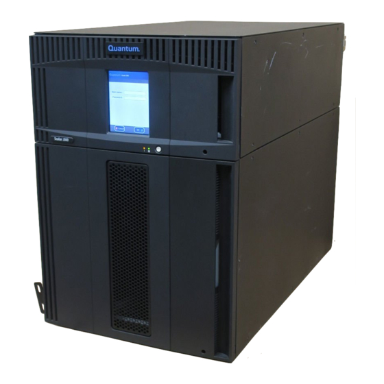
Page 31: Figure 1 5U Library Configuration (Standalone Control Module)
Chapter 1 Description Library Configuration The 5U, 14U, and 23U libraries are the base Scalar i500 systems. By adding 9U expansion modules, you can upgrade a base system to: • A 32U library, consisting of one 5U control module and three 9U expansion modules •... -
Page 32: Figure 2 14U Library Configuration
Chapter 1 Description Library Configuration Figure 2 14U Library Configuration (5U Control Module Plus One 9U Expansion Module) Control module Expansion module Scalar i500 User’s Guide... -
Page 33: Figure 3 23U Library Configuration
Chapter 1 Description Library Configuration Figure 3 23U Library Configuration (5U Control Module Plus Two 9U Expansion Modules) 5U control module 9U expansion module 9U expansion module Scalar i500 User’s Guide... -
Page 34: Modules
Modules Scalar i500 libraries are modular, and you can increase the size at any time. The three base systems for the Scalar i500 library are as follows: • The 5U library, consisting of a control module •... -
Page 35: Control Module
Chapter 1 Description Modules The control module is required in any Scalar i500 library configuration. Control Module The control module contains the robotic controls, library control blade (LCB), and touch screen display. The control module also contains an import/export (I/E) station, fixed storage slots, tape drives, and at least one power supply. -
Page 36: Figure 4 Base Systems Plus Expansion Modules
5U Control 9U Expansion 9U Expansion Module Module Module 5U Control 9U Expansion 9U Expansion 9U Expansion Module Module Module Module 5U Control 9U Expansion 9U Expansion 9U Expansion 9U Expansion Module Module Module Module Module Scalar i500 User’s Guide... -
Page 37: Front Panel Components
Front Panel Components Figure 5 shows the front panel components of the library. The paragraphs following Figure 5 describe the components in detail. Figure 5 Front Panel Components Access door Operator panel I/E station Front power button Scalar i500 User’s Guide... -
Page 38: Access Door
When an I/E station slot is assigned to a partition, only the assigned partition can access that slot. The operator panel is the touch screen display device upon which the Operator Panel graphical user interface (GUI) appears. The operator panel is located on Scalar i500 User’s Guide... -
Page 39: Front Power Button
242 for instructions on how to shut down or restart the library safely. Back Panel Components Figure 6 shows the back panel components of the library. The paragraphs following Figure 6 describe the components in detail. Scalar i500 User’s Guide... -
Page 40: Figure 6 Back Panel Components
Figure 6 Back Panel Components Library control blade (LCB) FC I/O blade (optional) FC I/O fan blades (required with FC I/O blades) Rear power switch Power supplies Upper and lower Ethernet ports on expansion module Module terminator connectors Scalar i500 User’s Guide... -
Page 41: Rear Power Switches
You can add a redundant power supply to each module. Installing one power supply in one module and another power supply in another module does not provide redundant power; the two power supplies must reside in the same module. Scalar i500 User’s Guide... -
Page 42: Scalar I500 User's Guide
AC OK or DC OK. Green • represents swap-mode power status. Blue Figure 7 shows the power supply LEDs. For more information on the behavior of the LEDs, see Power Supply LEDs on page 514. Scalar i500 User’s Guide... -
Page 43: Library Control Blade
The LCB also provides internal communication to Fibre Channel (FC) I/O blade slots. The LCB has four Ethernet ports, supporting a total of four FC I/O blades in the library. Scalar i500 User’s Guide... -
Page 44: Scalar I500 User's Guide
Amber • represents power-control status. Blue Figure 8 shows the location of the LCB components, including LEDs. For more information on the behavior of the LCB LEDs, see Blade Port LEDs on page 509. Scalar i500 User’s Guide... -
Page 45: Fibre-Channel Input/Output Blades
Expansion modules support optional Fibre Channel (FC) Input/Output Input/Output Blades (I/O) blades that provide connections for FC tape drives in the library. Each FC I/O blade has an embedded controller that provides connectivity and features that enhance the performance and reliability of Scalar i500 User’s Guide... -
Page 46: Scalar I500 User's Guide
506. For information on configuring I/O blades, see Working With FC I/O Blades on page 109. For information on installing and cabling FC I/O blades and FC tape drives, see Chapter 12, Installing, Removing, and Replacing. Scalar i500 User’s Guide... - Page 47 FC I/O fan blade, including the LED. The single amber LED represents health status. For more information on the behavior of the FC I/O fan blade LED, see Tape Drive LEDs on page 511. Scalar i500 User’s Guide...
-
Page 48: Robotic System And Barcode Scanner
X, Y, and Z motion coordinates. The robotic system and the barcode scanner work together to identify the locations of resources within the library. Scalar i500 User’s Guide... -
Page 49: Tape Drive Support
Supported Components on page 530 for a list of tape drives and media supported by the Scalar i500 library. The library supports mixing different tape drive types within the library and within partitions. For information on how to do this, see... -
Page 50: Library Features
Adding a Tape Drive page 444. Library Features This section describes several features of Scalar i500 libraries. The operator panel is located on the front door of the control module and User Interface allows you to work locally on the library via the user interface. The Web client allows you to view and perform library functions from remote sites and is accessible through a browser. -
Page 51: Control Path Modification
For more information, see Working With Control Paths on page 86. Scalar i500 tape libraries support WORM (write once, read many) Support for WORM technology in LTO-3, LTO-4, LTO-5 and LTO-6 tape drives. WORM allows non-rewriteable and non-erasable data to be written and provides extra data security by prohibiting accidental data erasure. -
Page 52: Figure 11 Library Location Coordinates
Note: The library location coordinates are different from the logical element addressing; see Understanding Logical Element Addressing on page 35 for more information.) Figure 11 Library Location Coordinates Scalar i500 User’s Guide... -
Page 53: Modules
A one-based numbering system is used. The full address of a an FC I/O blade bay is in the form of [module,FC I/O blade bay]; for example: [1,1], [-1,2]. Scalar i500 User’s Guide... -
Page 54: Ethernet Expansion Blades
The top tape drive in the module and partition is always number 256. The tape drive beneath that is 257, and so on until all tape drives in that module/partition have been accounted for. Numbering Scalar i500 User’s Guide... -
Page 55: Cartridge Slot Logical Element Addressing
I/E station slot in the uppermost module that contains I/E station slots, and continues sequentially downward. This top slot has element address 16. The slot beneath that is 17, and so on. Scalar i500 User’s Guide... -
Page 56: Scalar I500 User's Guide
STATUS command, it will process the new number and recalculate all of the slot addresses. Figure Figure 12 on page 38 for a simple example of element addressing in a 14U library with a single partition. Scalar i500 User’s Guide... -
Page 57: Figure 12 Logical Element Addressing, 14U, One Partition, Six Tape
Addressing, 14U, One Partition, Six Tape Drives Installed Note: Empty drive bay element addresses are skipped. This picture assumes six tape drives are installed. Tape cartridge slots in partition I/E station slots Tape drives Unused slots Scalar i500 User’s Guide... -
Page 58: Chapter 2 Understanding The User Interface
Chapter 2 Understanding the User Interface The user interface of Scalar i500 libraries is available in two formats: the operator panel and the Web client. Operations on the library can be performed locally on the control module using the operator panel or remotely on your computer using the Web client. -
Page 59: Common User Interface Elements
See Troubleshooting “Library Not Ready” Messages on page 496 for more information on “Library Not Ready” messages displayed in the header. Figure 13 Figure 14 show the operator panel and the Web client interfaces. Scalar i500 User’s Guide... -
Page 60: Figure 13 Operator Panel User Interface
Chapter 2 Understanding the User Interface Common User Interface Elements Figure 13 Operator Panel User Interface Figure 14 Web Client User Interface Scalar i500 User’s Guide... -
Page 61: System Summary And Subsystem Status
NOT update if you open, close, or resolve the Occurrence RAS Ticket. You can change the order in which the RAS tickets are displayed by clicking any header item (for example, Priority, Last Occurrence, or Name). Scalar i500 User’s Guide... -
Page 62: Home Page
Audible feedback, or “key click” sounds, are generated when a user presses a button on the operator panel. Users can choose to disable the audible feedback. See Configuring System Settings on page 126. Scalar i500 User’s Guide... -
Page 63: Operator Panel Keypads
You must disable Web browser popup blockers to use the Web client interface and the library’s online Help. Add the Scalar i500’s Internet Protocol (IP) address to the list of trusted/allowed sites on your Scalar i500-supported browser, so the Web client pages will automatically refresh. -
Page 64: Menu Trees
Administrators have access to all menu commands; users with user privileges have more limited access. Table 1 lists the Web client menus. Some menu commands are available only to administrators. I/O blade menu items are available for libraries that contain I/O blades. Scalar i500 User’s Guide... -
Page 65: Table 1 Web Client Menus
• Encryption Addresses Certificate • Contact • Import Information • Export • Network Management • Encryption Key • Network • Import • SNMP • Export • SNMP Trap • Retrieve SKM Logs Registrations (if SKM enabled) Scalar i500 User’s Guide... -
Page 66: Scalar I500 User's Guide
Administrators only. Available only when the library contains I/O blades. Table 2 lists the operator panel menus. Some menu commands are available only to administrators. I/O blade menu items are available for libraries that contain I/O blades. Scalar i500 User’s Guide... -
Page 67: Table 2 Operator Panel Menus
• Network Mgmt • Enable SSL • IP version 4 • Enable SNMP V1/V2 • IP version 6 (if enabled) • Enable IPv6 • Port Settings • Enable SMI-S • Control Path • Unlabeled Media Detection Scalar i500 User’s Guide... -
Page 68: Scalar I500 User's Guide
• View Last Detailed Log • E-mail Last Detailed Log • Blade Info • Port Info • Command History Log Administrators only. Available only when the library contains I/O blades. Visible only when host mapping has been enabled. Scalar i500 User’s Guide... -
Page 69: User Privileges
See Working With User Accounts on page 97 for more information on setting user privilege levels. Three types of users are defined in Scalar i500 libraries: • have access to the entire physical library and all of its Administrators partitions, and can configure the library and set up user and administrator accounts. -
Page 70: User Access
See Table 1 on page 46 for the Web client menu tree and privilege level information. See Table 2 page 48 for the operator panel menu tree and privilege level information. Scalar i500 User’s Guide... -
Page 71: Chapter 3 Configuring Your Library
Chapter 3 Configuring Your Library Once you have installed the hardware as described in the Scalar i500 Getting Started Guide, you are ready to configure your library’s settings. A Setup Wizard helps you get started configuring your library, and menu commands on both the operator panel and the Web client allow you to reconfigure your library at any time. -
Page 72: About The Setup Wizard
After that, administrators access the Setup Wizard any time via the Web client or use commands on the menus to modify all Setup Operations library settings, including network settings. See Completing the Library Configuration With Menu Commands on page 54. Scalar i500 User’s Guide... -
Page 73: Using The Default Administrator Account
You cannot delete the default administrator account or modify Note: the user name. You can, however, change the password. If you misplace the password for the default administrator Note: account, contact Quantum Technical Support (see Getting More Information or Help on page 8). Completing the Library... -
Page 74: Using The Setup Wizard
You cannot log into the Web client until you have configured the network settings. • On the screen, do If you are using IPv4: Setup Wizard: Enable IPv6 NOT select the check box. Click . Configure the Enable IPv6 Next network settings. Scalar i500 User’s Guide... -
Page 75: Scalar I500 User's Guide
• You cannot log in to the library from the Web client until you have configured network settings on the operator panel. To change IPv4 settings and configure IPv6 settings, go to Setup > Network Mgmt Scalar i500 User’s Guide... -
Page 76: Default Configuration Settings
The menus contain most configuration Setup Operations options, including those in the . This section includes Setup Wizard detailed descriptions of the configuration tasks, including how and when to access them through the menus. Setup Operations Scalar i500 User’s Guide... -
Page 77: Scalar I500 User's Guide
494. Note: Setup Wizard operations cannot be performed concurrently by multiple administrators logged in from different locations. You can access the screens, but you cannot apply changes while another administrator is performing the same operation. Scalar i500 User’s Guide... -
Page 78: Accessing The Web Client
• Simple Network Management Protocol (SNMP) settings that allow you to use an external management application to monitor the status of the library. For more information, see Configuring SNMP Settings on the Library on page 63. Scalar i500 User’s Guide... -
Page 79: Modifying Network Settings
(LCB) just below the three LEDs. The LCB is located at the back of the control module. Make sure the other end of the Ethernet cable is installed in the appropriate LAN port on your LAN. Scalar i500 User’s Guide... -
Page 80: Scalar I500 User's Guide
Secondary DNS Address as an IP address. This text box is available only if DHCP is disabled. • (operator panel only) allows you to change the Port Settings autonegotiate mode, speed, and duplex settings on the Ethernet port. Scalar i500 User’s Guide... -
Page 81: Enabling Ssl
The default SSL setting is . Disabling SSL settings creates an Disabled unencrypted connection from a Web browser to the Web client. See the Scalar Intelligent Libraries SMI-S Reference Guide (6-01317-xx) for further configuration and access details. Scalar i500 User’s Guide... -
Page 82: Configuring Snmp Settings On The Library
SNMP information can be obtained from the library using SNMP Traps and GET queries. For more information about SNMP, see the Scalar i500 Basic SNMP Reference Guide (6-01370-xx). For information on integrating MIBs with an SNMP management application, contact your network management application vendor. -
Page 83: Scalar I500 User's Guide
DNS is enabled. Otherwise, IP addresses must entered. For information on DNS, see Modifying Network Settings page 60. • — the port number of the external application you want to Port register. The default port number for an external application is 162. Scalar i500 User’s Guide... -
Page 84: Scalar I500 User's Guide
Progress Window Progress to resolve any issues that occur during the operation. Window See the Scalar i500 Basic SNMP Reference Guide (6-01370-xx) for further configuration and access details. Note: This operation should not be performed concurrently by multiple administrators logged in from different locations. -
Page 85: Scalar I500 User's Guide
32 characters. See the Scalar i500 Basic SNMP Reference Guide (6-01370-xx) for further configuration and access details. You cannot modify the SNMP community string from the operator panel. -
Page 86: Scalar I500 User's Guide
Administrators can download the SNMP MIB from the library. The MIB can then be installed on an SNMP external management application. For more information about the library MIB, see the Scalar i500 Basic SNMP Reference Guide(6-01370-xx) or contact Quantum Technical Support (see Getting More Information or Help on page 8). -
Page 87: Working With Partitions
Note: You may not mix drive vendor types (for example, HP and IBM) in partitions that are configured for library managed encryption (see Step 6: Configuring Partitions for Library Managed Encryption on page 184). Scalar i500 User’s Guide... -
Page 88: Table 3 Number Of Partitions Supported
Before permanently removing an expansion module from Caution: your library, you need to perform a set of configuration operations that includes deleting all partitions. See Deleting Partitions on page 74 and Removing the Expansion Module on page 371. Scalar i500 User’s Guide... -
Page 89: Automatically Creating Partitions
By default, the library applies the Standard barcode format to each partition. You can change this setting by modifying the partitions after it has been created. For information on modifying partitions, see Modifying Partitions on page 73. Scalar i500 User’s Guide... -
Page 90: Manually Creating Partitions
Emulation Type different library type to the host. In most cases, you can ignore this setting and just use the default. However, if your host application does not support the default and cannot recognize the partition using Scalar i500 User’s Guide... -
Page 91: Scalar I500 User's Guide
This makes the partition appear to the host as the selected library type and should allow the host to communicate. • ADIC Scalar i500 (default) • Quantum Scalar i500 •... -
Page 92: Mixing Tape Drive Types Within Partitions
For more information on setting the control path, see Working With Control Paths on page 86. The library automatically takes the partition offline before modifying it and places the partition back online after it is modified. Scalar i500 User’s Guide... -
Page 93: Deleting Partitions
Unload all tape drives and export all cartridges assigned to the partition that is to be deleted. After exporting the cartridges, remove them from the I/E station. For more information, see Unloading Tape Drives page 256 and Exporting Media on page 253. Scalar i500 User’s Guide... -
Page 94: Changing Partition Access
• — Determines the user’s access privileges. See User Privilege Level Privileges on page 50 for more information on user privilege levels. • — the partitions to which the user has access. Partition Access Scalar i500 User’s Guide... -
Page 95: Taking A Partition Online Or Offline
To take the library offline, change the mode of all partitions from online to offline. Note: When changing the partition mode from online to offline, all host application commands in progress at the start of the mode change are completed. Scalar i500 User’s Guide... -
Page 96: Disabling/Enabling Manual Cartridge Assignment
Unit Attention 6/2801 depends on the number of configured partitions: • If multiple partitions are defined, the host application is not notified when the I/E station has been accessed. Media presence in the I/E station is reported to any partition requesting it. Scalar i500 User’s Guide... -
Page 97: Configuring Cleaning Slots
The maximum number of cleaning slots that can be configured is four. To disable AutoClean, configure zero cleaning slots. Administrators can configure cleaning slots during the initial library configuration and at any time after that, as long as unassigned slots are Scalar i500 User’s Guide... -
Page 98: Configuring I/E Station Slots
12 I/E station slots. The available library configurations support a minimum of six I/E slots in the 5U library to a maximum of 54 I/E slots in the 41U library configuration. You can also choose to Scalar i500 User’s Guide... -
Page 99: Scalar I500 User's Guide
Therefore, a 14U library can contain a minimum of six and a maximum of 18 dedicated I/E station slots. Table 4 lists the number of I/E station slots available per library for all base library configurations. Scalar i500 User’s Guide... -
Page 100: Table 4 Number Of I/E Station Slots Available
• The library configures I/E slots in the control module I/E station first and then works outward to the I/E stations in the expansion modules. I/E stations in expansion modules below the control module have precedence over I/E stations in expansion modules above the control module. Scalar i500 User’s Guide... -
Page 101: Configuring Zero I/E Station Slots
I/E station and then configure the I/E station slots. This operation cannot be performed concurrently by multiple Note: administrators logged in from different locations. You can access the screen, but you cannot apply changes while another administrator is performing the same operation. Scalar i500 User’s Guide... -
Page 102: Setting Tape Drive Parameters
For SCSI tape drives, you can set the SCSI ID to a value from 0 to 15. The library assigns the following default SCSI IDs to SCSI tape drives: • Control module: 1 and 2 • Each expansion module: 3, 4, 5, and 6 Scalar i500 User’s Guide... -
Page 103: Scalar I500 User's Guide
Point. • The requested topology connection mode can be set to one of the following: • — Auto-configure trying L-Port first Auto (LN) • — Force L-Port Loop (L) • — Force N-Port Point to Point Scalar i500 User’s Guide... -
Page 104: Scalar I500 User's Guide
On the Web client, the screen displays tape Note: Drive Settings drive information in tables. Bold column headings in the tables can be sorted. For example, selecting the column Location heading will sort by location coordinates. Scalar i500 User’s Guide... -
Page 105: Working With Control Paths
No FC I/O The first tape You must select a tape drive as the control path. blades combination drive assigned of tape drive to the partition interface types (SCSI, FC, or SAS) Scalar i500 User’s Guide... -
Page 106: Scalar I500 User's Guide
Do not select an FC tape drive as control path if it is Caution: connected to an FC I/O blade. The control path will be filtered out by the I/O blade and will not be visible to the host. Scalar i500 User’s Guide... -
Page 107: Obtaining And Installing A License Key
32). This section describes how to license these features on your library, in the following sections: • About License Keys • Viewing Licenses and License Keys • Obtaining a License Key • Applying a License Key Scalar i500 User’s Guide... -
Page 108: About License Keys
Quantum issues you a license key certificate. The license key certificate contains an authorization code that enables you to retrieve your license key from the Quantum Web site. Once you install the license key on the library, the feature becomes available. -
Page 109: Viewing Licenses And License Keys
See Getting More Information or Help on page 8. 2 Upon receipt of your order, Quantum will ship you a license key certificate containing your authorization code. Note: If you order more than 46 COD slots: COD licenses come in 46-slot increments. -
Page 110: Applying A License Key
” may appear instead of the Factory actual license key. If you need to retrieve the license key in this case, contact Quantum Technical Support (see Contacts on page 7). 7 Type the authorization code from your License Key Certificate in the text box. -
Page 111: Setting Customer Contact Information
The library uses the library e-mail account whenever library e-mail services are used, such as when the library automatically sends e-mail notifications about library issues. Before configuring the e-mail account, ask your network administrator for an IP address, valid login account (optional), and valid password Scalar i500 User’s Guide... -
Page 112: Scalar I500 User's Guide
(for example, “John.User”). The login account name can contain the following special characters: @ and #. • is the password for the account that you specified in Password text box. The password can contain the Login Account following special characters: @ and #. Scalar i500 User’s Guide... -
Page 113: Working With Ras E-Mail Notifications
The library supports a maximum of 20 e-mail notification recipients, including the default support e-mail notification. Note: RAS e-mail notifications are closed when the library reboots. From the operator panel, select Tools > System Settings configure this setting. Scalar i500 User’s Guide... -
Page 114: Creating Ras E-Mail Notifications
Such information will appear in the body of the e-mail and can help technical support personnel to troubleshoot the library. Scalar i500 User’s Guide... -
Page 115: Modifying Ras E-Mail Notifications
The e-mail address, techsup@quantum.com, cannot be modified. The path to open the appropriate screen is as follows: • From the Web client, select Setup > Notifications > RAS > Receiver Addresses > Delete Scalar i500 User’s Guide... -
Page 116: Working With User Accounts
The default administrator account is used to perform the initial configuration of the library. If you misplace the password for the Scalar i500 User’s Guide... -
Page 117: Creating Local User Accounts
Chapter 3 Configuring Your Library Working With User Accounts default administrator account, contact Quantum Technical Support. See Getting More Information or Help on page 8. User Privileges on page 50 for more information on library permission levels. For information on changing passwords, see Modifying Local User Accounts on page 98. -
Page 118: Deleting Local User Accounts
The library Web client does not allow you to create, modify, or delete user account information on an LDAP server. This must be done by the directory service provider. For more information on working with local user accounts, see About Local User Accounts on page 97. Scalar i500 User’s Guide... -
Page 119: Scalar I500 User's Guide
LDAP settings on the library (see Testing LDAP Settings on page 103). Since most normal users will not be members of both these groups, you may need to create a special or temporary user specifically for this purpose. Scalar i500 User’s Guide... -
Page 120: Scalar I500 User's Guide
103. Configuring LDAP on the Library Before configuring LDAP, obtain the following LDAP parameters from your network administrator. You need to enter these parameters in the screen on the Web client. Setup - Remote Authentication Scalar i500 User’s Guide... -
Page 121: Scalar I500 User's Guide
Figure Figure 15 on page 103. • — The value of the Common Name attribute for Library Admin Group the group entry on the LDAP server associated with library users who have administrator-level privileges (see User Privileges Scalar i500 User’s Guide... -
Page 122: Figure 15 Ldap Setup Example
Otherwise, any changes you made will be lost and will not be tested. To test the settings, you must type a user name and password, then click button. Test Settings The user you use for the test must be a member of Scalar i500 User’s Guide... -
Page 123: Configuring Kerberos
— The key distribution center (in other words, the KDC (AD Server) server on which Kerberos/Active Directory is installed). Example: mycompany.com:88 • — The domain portion of the library’s fully qualified Domain Mapping domain name. Example: mycompany.com Scalar i500 User’s Guide... -
Page 124: Scalar I500 User's Guide
The account name will be used for <computer account> fields shown in the following steps. 5 At the command prompt, map SPN to the computer account. Use the following format: setspn -A library/<fqdn of library> <computer account> For example: setspn -A library/delos.dvt.mycompany.com kerbtest Scalar i500 User’s Guide... -
Page 125: Setting The Date, Time, And Time Zone
Note: The following operations should not be performed concurrently by multiple administrators logged in from different locations. You can access the appropriate screens, but you cannot apply changes while another administrator is performing the same operation. Scalar i500 User’s Guide... -
Page 126: Setting The Date And Time Manually
Web client. Date & Time Setup Details on NTP settings include: • NTP servers must be configured in available in groups of 3 or more, with one exception: a single NTP server configuration is also allowed. Scalar i500 User’s Guide... -
Page 127: Setting The Time Zone
You can only set daylight saving time on the Web client. The path to open the appropriate screen is as follows: • From the Web client, select Setup > Date & Time Scalar i500 User’s Guide... -
Page 128: Working With Fc I/O Blades
Identifying FC I/O Blades on page 502 • Resetting FC I/O Blade Ports on page 504 Note: FC I/O blade menu commands are available for use only when FC I/O blades are installed in the library. Scalar i500 User’s Guide... -
Page 129: Configuring Fc I/O Blade Ports
The paths to open the appropriate screens are as follows: • From the Web client, select Setup > FC I/O Blades > Port Configuration • From the operator panel, select Setup > I/O Blades > Port Configuration Scalar i500 User’s Guide... -
Page 130: Fc I/O Blade Internal Virtual Port For Media Changers
Changers devices, except those that are defined in association with drive-based access (also known as “LUN-1”). The Scalar i500 library can have up to 18 partitions. These internal virtual ports are not configurable via channel zoning; thus, all media changer devices are accessible via ports 1 and 2 of each FC I/O blade present within the library. -
Page 131: Scalar I500 User's Guide
LUN mapping on the FC I/O blade. • After configuring channel zoning, save the library configuration. For instructions on how to save the library configuration, see Saving and Restoring the Library Configuration on page 494. Scalar i500 User’s Guide... -
Page 132: Managing Fc Hosts And Host Mapping
Administrators can enable or disable the optional FC host mapping Host Mapping feature. This feature is disabled by default. When host mapping is enabled, you can add, modify, and delete hosts as well as configure FC host mapping. Scalar i500 User’s Guide... -
Page 133: Viewing Fc Host Information
You can Connection also modify and delete an existing FC host connection. You can perform these operations without down the library. You can add up to 32 FC host connections per FC I/O blade. Scalar i500 User’s Guide... -
Page 134: Scalar I500 User's Guide
— The host port number. Host Port • — The appropriate host operating system. Type You cannot modify the WWPN. If you want to change the WWPN, you must delete and re-create the FC host connection. Scalar i500 User’s Guide... -
Page 135: Host Mapping - Overview
LUNs 3, 5, 7 and 9 for a specific host server. There is also an internal (i.e., not attached to a port) controller device presented at LUN 0 by default. The controller device facilitates initialization and device discovery. In some instances it may be useful to Scalar i500 User’s Guide... -
Page 136: Host Mapping Vs. Channel Zoning
Note: On the operator panel, the host mapping screens ( Setup > FC ) are not available unless FC host I/O Blades > Host Mapping mapping is enabled. See Enabling/Disabling FC Host Mapping on page 113. Scalar i500 User’s Guide... -
Page 137: Configuring Host Mapping
— Current logical unit number (LUN) assignment. Assign a new LUN number for the device. Note: The operator panel host mapping configuration screens show less information about each device; however, you still select the host and device(s) and configure the LUN number(s(.) Scalar i500 User’s Guide... -
Page 138: Configuring Fc Host Port Failover
(1 or 2) on an I/O blade can assume the identity and LUN mapping configuration of the designated “active” target port if the active port fails. Host port failover enables the library to continue operations without requiring you to reconfigure the host or the SAN. Scalar i500 User’s Guide... -
Page 139: Scalar I500 User's Guide
When the failed port is repaired, the port must be re-enabled to make it available for host port failover as the standby or active port. For more information, see Repairing and Enabling a Failed Target Port on page 121. Scalar i500 User’s Guide... -
Page 140: Repairing And Enabling A Failed Target Port
RAS ticket that was generated when the host port failover occurred. For information on viewing and resolving RAS tickets, see About RAS Tickets on page 487. Once the port has been repaired, you can enable it. Details on enabling a repaired target port include: Scalar i500 User’s Guide... -
Page 141: Scalar I500 User's Guide
The paths to open the appropriate screens are as follows: • From the Web client, select Setup > I/O Blades > Host Port Failover • From the operator panel, Setup > I/O Blades > Host Port Failover Scalar i500 User’s Guide... -
Page 142: Working With Data Path Conditioning
Note: This operation should not be performed concurrently by multiple administrators logged in from different locations. You can access the appropriate screens, but you cannot apply changes while another administrator is performing the same operation. Scalar i500 User’s Guide... -
Page 143: Configuring Library Security Settings
129). In order to run SNMP, the port must be open and the SNMP services must be enabled. • — Opens port 5988 to allow SMI-S communication to the SMI-S library. This setting is enabled by default. Scalar i500 User’s Guide... -
Page 144: Configuring The Internal Network
IP address from the list on the screen. You can select from nine IP addresses. screen is only accessible from the Internal Network Configuration operator panel. The path to open the appropriate screen is as follows: • From the operator panel, select Tools > Internal Network Scalar i500 User’s Guide... -
Page 145: Configuring System Settings
The setting is Unload Assist enabled by default. The paths to open the appropriate screens are as follows: Scalar i500 User’s Guide... -
Page 146: Tape Drive Logical Sn Addressing
If this happens, you will need to reconfigure the tape drives in your backup application. The path to open the appropriate screen is as follows: • From the operator panel, select Setup > System Settings Scalar i500 User’s Guide... -
Page 147: Manual Cartridge Assignment
Enables Secure Socket Layer (SSL) for secure data transmission between Enable SSL the library and remote clients. This option is disabled by default. The path to open the appropriate screen is as follows: • From the operator panel, select Setup > System Settings Scalar i500 User’s Guide... -
Page 148: Enable Snmp V1/V2
With the Unlabeled Media Detection feature, you can configure the library to detect and report which slots contain media with unreadable barcodes. Since cartridges with unreadable barcodes will not work for Scalar i500 User’s Guide... -
Page 149: Scalar I500 User's Guide
The paths to open the appropriate screens are as follows: • From the operator panel, select Tools > System Settings • From the Web client, select Setup > System Settings Scalar i500 User’s Guide... -
Page 150: Auto-Ticket Closure
1 Upgrade library firmware to version 600G or later. 2 For all HP LTO-5 FC tape drives that you plan to enable for FIPS, upgrade firmware to the latest version qualified with the Scalar i500 library (see the Scalar i500 Release Notes for qualified firmware levels). -
Page 151: Viewing Fips Status On The Library
FIPS Enabled item. This item only displays when the tape drive is an HP LTO-5 Fibre Channel tape drive. The item displays “Yes” when FIPS is enabled on the drive and “No” when FIPS is disabled. Scalar i500 User’s Guide... -
Page 152: Configuring Operator Panel Display Settings
Setup > Register screen to complete registration. Library You cannot register the library from the operator panel. The path to open the appropriate screen is as follows: • From the Web client, select Setup > Register Library. Scalar i500 User’s Guide... -
Page 153: Chapter 4 Advanced Reporting
• — Lists information on all media that have ever been Media Usage Log in the library. In addition, you can automatically e-mail any of the reports and logs to designated recipients at specified, scheduled times. Scalar i500 User’s Guide... -
Page 154: About The Advanced Reporting License
The Advanced Reporting license applies to your entire library, regardless of library size. This means you only need to purchase the license once. If you increase the size of your library, your existing license applies to your new library configuration. Scalar i500 User’s Guide... -
Page 155: Working With Advanced Reporting Reports
The following information is collected for each tape drive installed in the library: • Drive location (module, row) • Drive serial number • Partition • Megabytes read • Megabytes written Scalar i500 User’s Guide... -
Page 156: Scalar I500 User's Guide
— The chart type. Select one of the following: Type • Rollup (default) — Displays the Grouping on the x-axis and the Attribute amount on the y-axis. • Trend — Shows how the Attribute amount changes over time for the selected Grouping. Scalar i500 User’s Guide... -
Page 157: Configuring The Media Integrity Analysis Report
10 tape drive error codes for each TapeAlert, displayed in columns with the headings , and so on. (The onscreen Error #1 Error #2 report does not contain the tape drive error codes.) Scalar i500 User’s Guide... -
Page 158: Scalar I500 User's Guide
— Specifies the chart type. Select one of the following: Type • Rollup (default) — Displays the number of TapeAlerts for the combination of Grouping and Attributes you selected (default). • Trend — Shows the occurrence of TapeAlerts over time. Scalar i500 User’s Guide... -
Page 159: Using Advanced Reporting Templates
15 characters. You can use only lowercase letters, numbers, and the underscore character (_) in template names. 3 Click Save The report appears in the drop-down list next to the button. Load Scalar i500 User’s Guide... -
Page 160: Loading And Reloading Advanced Reporting Data
To do this, click the button in the Report Data section of either report configuration Delete page. This deletes the data for the Drive Resource Utilization report both and the Media Integrity Analysis report. Scalar i500 User’s Guide... -
Page 161: Saving And E-Mailing Report Data Files
, and click Retrieve the Report Data File E-mail 4 To e-mail the report data as a .csv file, type the name of a recipient in the empty field next to the button, then click E-mail E-mail Scalar i500 User’s Guide... -
Page 162: Configuring And Viewing The Media Security Log
• Date and time of media removal • Tape cartridge barcode • Type of removal (expected or unexpected) • Slot location coordinates (of the slot the cartridge is missing from) • Slot type (I/E, storage, or cleaning) Scalar i500 User’s Guide... -
Page 163: Viewing The Media Usage Log
— Media cartridge manufacturing date (format: YYYYMMDD) Date • — Media type Type • — Cartridge mount count Mounts • — Recovered read errors • — Unrecovered read errors • — Recovered write errors • — Unrecovered write errors Scalar i500 User’s Guide... -
Page 164: Automatically E-Mailing Advanced Reporting Reports And Logs
You can create up to 20 e-mail recipients. If you want to send the same recipient a different set of reports, you can enter the same e-mail address more than once, with different reports selected for each. Each entry counts as a unique recipient toward the 20 total. Scalar i500 User’s Guide... -
Page 165: Scalar I500 User's Guide
The path to open the appropriate screen is as follows: • From the Web client, select Setup > Notifications > Advanced Reporting > Receiver Addresses Scalar i500 User’s Guide... -
Page 166: Chapter 5 Capacity On Demand
Chapter 5 Capacity on Demand All Scalar i500 library configurations ship with the purchased number of slots pre-activated. The number of available pre-activated slots begins at 41 for all library configurations and increases in 46-slot increments to a maximum of 409 slots in the 41U library configuration. -
Page 167: Table 6 Available Slots And Cod Upgrades Per Configuration
133, 179, 225 179, 225, 271, 179, 225, 271, Slots 317, 363, 409 Available 87, 133 87, 133, 87, 133, 179, 87, 133, 179, COD Slot 179, 225 225, 271, 317 225, 271, 317, Upgrades 363, 409 Scalar i500 User’s Guide... -
Page 168: Chapter 6 Storage Networking
Forcing Data Path Failover • Configuring Host Access • Registering a Host for Host Access • Enabling Tape Drives for Host Access • Mapping a Host to Tape Drives and Partitions • Modifying a Host • Deleting a Host Scalar i500 User’s Guide... -
Page 169: About The Storage Networking License
SNW features. If you remove all SNW features from a tape drive, then the license becomes available to use on another tape drive. For more information on licensing, see Obtaining and Installing a License on page 88. Scalar i500 User’s Guide... -
Page 170: Configuring Control Path Failover
The World Wide Port Name (WWPN) for this virtual port is listed in the library’s System Information Report in the Library Partitions section under Control Path (see Viewing the System Information Report page 271). Scalar i500 User’s Guide... -
Page 171: Basic Control Path Failover (Bpf)
• A Storage Networking license must be installed on the library and the associated drive count must be sufficient to cover all drives involved in the multi-path configuration. • The tape drives must NOT be connected to an FC I/O blade. Scalar i500 User’s Guide... -
Page 172: Advance Control Path Failover (Acpf)
To force a control path failover: 1 From the Web client, click Tools > Drive Operations Scalar i500 User’s Guide... -
Page 173: Figure 19 Forcing Control Path Failover
For each partition, the Standby following information is listed: Column Indicates Location of the current control path tape Active Drive drive. Active Status Ready status of the current control path tape drive. Scalar i500 User’s Guide... -
Page 174: Figure 20 Forcing Control Path Failover
The standby tape drive must be “ready” and “connected” in order to force a failover. 4 Click Apply The new active tape drive location displays in the Active Drive column. The new standby tape drive location displays in the Standby column. Drive Scalar i500 User’s Guide... -
Page 175: Configuring Data Path Failover
A tape drive can be configured for both data path failover and control path failover. If both are configured, the control path will not fail over to another tape drive unless both ports on the control path tape drive fail. Scalar i500 User’s Guide... -
Page 176: Basic Data Path Failover
Details about data path failover include: • The tape drive firmware must be at the version qualified with the Scalar i500 library (see the Scalar i500 Release Notes for qualified firmware levels). • The library must have a Storage Networking license sufficient to cover the tape drive(s) on which you want to configure data path failover. -
Page 177: Advanced Data Path Failover (Adpf)
To configure a tape drive for advanced data path failover, you need the following: • A Storage Networking license must be installed on the library and the associated drive count must be sufficient to cover all drives involved in the advanced data path configuration. Scalar i500 User’s Guide... -
Page 178: Enabling Data Path Failover
Setup - Drive Settings 3 For each tape drive on which you want to enable data path failover, do the following: a First, change the setting to Requested Topology Point to Point b Then select the check box. Scalar i500 User’s Guide... -
Page 179: Forcing Data Path Failover
Figure 22 Enabling Data Path Failover Forcing Data Path You can manually swich the active Fibre Channel port on a DPF-enabled Failover tape drive by forcing a failover. You might want to force a failover to Scalar i500 User’s Guide... -
Page 180: Figure 23 Forcing Data Path Failover
The port currently being used as the data path is listed in the Active Port column. The column will state “No Link” if neither port is Active Port connected. Scalar i500 User’s Guide... -
Page 181: Figure 24 Forcing Data Path Failover
If the new active port does not display, refresh the page in the browser. Note: The library will issue a RAS ticket if the forced failover fails. The library will not issue a RAS ticket if the forced failover succeeds. Scalar i500 User’s Guide... -
Page 182: Configuring Host Access
However, unregistered hosts and registered hosts that are not mapped to that partition do still have access and can send commands to any non-host-access-enabled tape drives in the partition, as well as any host-access-enabled tape drives in the partition to which they are mapped. Scalar i500 User’s Guide... -
Page 183: Registering A Host For Host Access
1 From the Web client, select Setup > Host Access > Host Registration 2 Click The library displays a list of all currently unregistered hosts that are connected to tape drives or FC I/O blades in the library. Scalar i500 User’s Guide... -
Page 184: Enabling Tape Drives For Host Access
5 Click to go to the next screen to map hosts to tape drives and Next partitions. (If the button does not appear on the screen, it means Next no tape drives are enabled for host access.) Scalar i500 User’s Guide... -
Page 185: Mapping A Host To Tape Drives And Partitions
Modifying a Host Changing these settings will not affect your host access connections.You cannot modify the WWPN of a registered host. If you need to change the WWPN, you must delete the host and create a new one. Scalar i500 User’s Guide... -
Page 186: Deleting A Host
To delete a host: 1 Click Setup > Host Access > Host Registration 2 Select a host and click Delete A dialog box opens asking you to confirm you want to delete the host. 3 Click Scalar i500 User’s Guide... -
Page 187: Chapter 7 Encryption Key Management
Encryption Key Management (EKM) is a licensable feature. You must have an EKM license installed on your library in order to use the encryption key management features described in this chapter. The Scalar i500 supports three encryption key management systems, which are described in Table 1. -
Page 188: Scalar I500 User's Guide
* The Key Management Interoperability Protocol (KMIP®) is a specification developed by OASIS®. Its function is to standardize communication between enterprise key management systems and encryption systems. The Scalar i500 library provides a KMIP version 1.0 compliant encryption solution. KMIP is only supported in certain environments. See the release notes for details. -
Page 189: Scalar I500 User's Guide
(EKM) solution on the library. This chapter also describes all of the EKM functions available on the library. Refer to the Quantum Encryption Key Manager User’s Guide, the Scalar Key Manager User’s Guide, or your KMIP key manager user’s guide for information on how to manage your encryption system outside of the library. -
Page 190: Kmip-Compliant Encryption Key Management
OASIS®. Its function is to standardize communication between enterprise key management systems and encryption systems. With version i7.2, the Scalar i500 provides a KMIP version 1.0 compliant encryption solution. KMIP is currently only supported with SafeNet® KeySecure servers. -
Page 191: About The Ekm License
Configuring Encryption Key Management on the Library Make sure your Q-EKM, SKM, or KMIP-compliant key servers are installed and running before configuring the library (see the Quantum Encryption Key Manager User’s Guide, the Scalar Key Manager User’s Guide, or your KMIP key manager user’s guide for instructions). -
Page 192: Scalar I500 User's Guide
HP LTO-6, and IBM LTO-7 tape drives. SKM media must have valid barcode labels affixed. SKM does not support the use of unlabeled media. • KMIP partitions must contain only IBM/HP LTO-4 and/or IBM/HP LTO-5 tape drives. Scalar i500 User’s Guide... -
Page 193: Scalar I500 User's Guide
Step 3: Configuring Encryption Settings and Key Server Addresses Configure encryption settings and key server information as follows: 1 From the Web client, select Setup > Encryption > System Configuration. The Setup - Encryption System Configuration screen displays (see Figure 25). Scalar i500 User’s Guide... -
Page 194: Figure 25 Setup - Encryption System Configuration
190). When enabled, this feature performs a check, at specified intervals, to make sure both key servers are connected to the library and functioning properly. The library generates a RAS ticket if there are problems. Scalar i500 User’s Guide... -
Page 195: Scalar I500 User's Guide
Once you add the “#” servers, you can change the failover order by clicking the up/down arrow buttons in the column. Order Scalar i500 User’s Guide... -
Page 196: Scalar I500 User's Guide
Quantum Encryption will not work properly. See the Key Manager User’s Guide for information on setting the port number on the Q-EKM key server. Scalar i500 User’s Guide... -
Page 197: Scalar I500 User's Guide
Security (TLS) communication certificates with valid dates must be installed on the library in order for the library to communicate securely with attached EKM servers. If you are using Q-EKM, skip this step. No TLS certificates are Note: required. Scalar i500 User’s Guide... -
Page 198: Scalar I500 User's Guide
Installing Your Own TLS Certificates on the Library on page 181. Checking for Current Certificates From the Tools menu, select EKM Management > Import Communication Certificates. The Tools - TLS Communication Certificate Import screen appears (see Figure 26). Scalar i500 User’s Guide... -
Page 199: Figure 26 Tls Communication Certificate Import Screen
Figure 26 TLS Communication Certificate Import Screen Installing Quantum-Supplied TLS Certificates on the Library Quantum-supplied TLS certificates are only available for use with SKM. The Quantum-supplied certificates come on a CD which you received. The TLS certificates are bundled in a single file. -
Page 200: Scalar I500 User's Guide
4 From the Select the Certificate Type to install drop-down list, select SKM. 5 Select the Use the Quantum Certificate Bundle check box. 6 Click the Browse button next to the Quantum Communication Certificate Bundle File field to locate the TLS certificate file. -
Page 201: Scalar I500 User's Guide
Incorrect date settings may interfere with the TLS certificates and cause the library to stop communicating with the key servers. 2 Place the TLS certificate files in a known location on your computer. Scalar i500 User’s Guide... -
Page 202: Scalar I500 User's Guide
(SKM or KMIP Key Manager). 5 Retrieve the certificate files as follows: For SKM a Make sure the Use the Quantum Certificate Bundle check box is deselected. Click Browse to retrieve the Root Certificate File. Click Browse to retrieve the Admin Certificate File. -
Page 203: Scalar I500 User's Guide
187. Step 6: Configuring Partitions for Library Managed Encryption Encryption on the Scalar i500 tape library is enabled by partition only. You cannot select individual tape drives for encryption; you must select an entire partition to be encrypted. -
Page 204: Table 7 Partition Encryption Methods
185 describes the partition encryption methods. Table 7 Partition Encryption Methods Encryption Method Description Enable Library Enables encryption support via a For use with EKM. Managed connected EKM key server for all tape drives and encryption-capable media assigned to the partition. Scalar i500 User’s Guide... -
Page 205: Scalar I500 User's Guide
Managed to Allow Application Managed, the data that was written to the tapes while the partition was configured for library managed encryption can no longer be read, until you change the partition back to Enable Library Managed. Scalar i500 User’s Guide... -
Page 206: Using Ekm Path Diagnostics
— Verifies that EKM services are running on the key servers. Path This test cannot run if the Drive test fails. Note: For Q-EKM only: • — Verifies that the key servers are capable of serving Config encryption keys. Scalar i500 User’s Guide... -
Page 207: Differences Between Manual And Automatic Ekm Path Diagnostics
For Q-EKM diagnostics in the following ways: • The Manual diagnostics takes affected partitions offline during the tests. When the tests complete, the partitions are returned to the online/offline state they were in before the tests began. Scalar i500 User’s Guide... -
Page 208: Using Manual Ekm Path Diagnostics
When you exit Diagnostics, the partitions automatically come back online. • Select Setup > Encryption > System Configuration or Setup > Encryption > Partition Configuration and click the link that says “Click here to run EKM Path Diagnostics.” Scalar i500 User’s Guide... -
Page 209: Using Automatic Ekm Path Diagnostics
RAS ticket if there are problems. • For Q-EKM: Automatic EKM Path Diagnostics is disabled by default. It is recommended that you leave Automatic EKM Path Diagnostics disabled, unless network interruptions are a common cause of encryption failures at your site. Scalar i500 User’s Guide... -
Page 210: Viewing And Changing The Active Key Server
For SKM and KMIP Key Manager: enabled by default and should always be left enabled. You should not need to disable it unless Quantum Support directs you to do so. For a list of tests performed, see Using EKM Path Diagnostics page 187. -
Page 211: Viewing Tape Drive Encryption Settings
For a complete description and instructions for using these features, see the library Web client online help. These functions are: • Generating Data Encryption Keys on page 193 • Sharing Encrypted Tape Cartridges on page 196 • Exporting the Native Encryption Certificate on page 197 Scalar i500 User’s Guide... -
Page 212: Scalar I500 User's Guide
The process is described in Step 6: Configuring Partitions for Library Managed Encryption on page 184. Generating Data Encryption Keys When 80% Depleted When an SKM server has used 80 percent of the data encryption keys assigned to a Scalar i500 User’s Guide... -
Page 213: Scalar I500 User's Guide
If a failure does occur during key generation, wait 10 minutes, then try to start it again. The key generation process will resume from where the error was encountered. Scalar i500 User’s Guide... -
Page 214: Scalar I500 User's Guide
7 Back up both SKM servers. You must back up both SKM servers every time you generate new data encryption keys to protect your data in case of catastrophic server failure. See the Scalar Key Manager User’s Guide for instructions on backing up the SKM servers. Scalar i500 User’s Guide... -
Page 215: Scalar I500 User's Guide
See Exporting Data Encryption Keys on page 198. 5 The source administrator e-mails the file containing the wrapped data encryption keys to the destination administrator. Scalar i500 User’s Guide... -
Page 216: Scalar I500 User's Guide
4 Click Close to close the Progress Window. 5 In the File Download dialog box that displays, click Save. 6 In the Save As dialog box that opens, choose a location in which to save the file, then click Save. Scalar i500 User’s Guide... -
Page 217: Importing Encryption Certificates
This function is available to administrators and only applies Note: to SKM servers. Both SKM servers must be connected and operational in order to export data encryption keys. Scalar i500 User’s Guide... -
Page 218: Scalar I500 User's Guide
— Exports all the keys that have ever been used to Export Used encrypt tape cartridges in the library performing this export. Also exports all keys that were imported onto the key server, via a “key import” operation, from any library. Scalar i500 User’s Guide... -
Page 219: Importing Data Encryption Keys
1 Before starting this process, read and follow the sequence of steps outlined in Sharing Encrypted Tape Cartridges on page 196. 2 Receive the file of encryption keys from the source SKM server and save it in a known location on your computer. Scalar i500 User’s Guide... -
Page 220: Accessing The Skm Server Logs
Accessing the SKM Server Logs • The library can download the audit and error logs from the SKM servers. You should not need to retrieve these logs unless Quantum Support directs you to do so. You can download the logs to your computer or e-mail them to a recipient. -
Page 221: Scalar I500 User's Guide
The path to open the appropriate screen is as follows: • From the Web client, select Reports > Log Viewer. Scalar i500 User’s Guide... -
Page 222: Fips-Certified Encryption Solution
The Quantum Scalar i500 now offers a FIPS 140-2 Level 1 certified encryption solution composed of the Scalar Key Manager and HP LTO-5 or LTO-6 Fibre Channel tape drives in a Scalar i500 library. FIPS mode can be enabled on the HP LTO-5 or LTO-6 tape drives via the library user interface. -
Page 223: Configuring The Library For Fips
2 For all HP LTO-5 or LTO-6 FC tape drives that you plan to enable for FIPS, upgrade firmware to the latest version qualified with the Scalar i500 library (see the Scalar i500 Release Notes for qualified firmware levels). 3 Shut down the library. -
Page 224: Enabling And Disabling Fips Mode On Hp Lto-5 And Lto-6 Tape Drives
Change the Encryption Method of a partition to Enable Library Managed. 2 Select the FIPS check box to enable FIPS mode for the partition. Clear the FIPS check box to disable FIPS mode for the partition. 3 Click Apply. Figure 28 Enabling FIPS Mode Scalar i500 User’s Guide... -
Page 225: Viewing Fips Status On The Library
FIPS Enabled item. This item only displays when the tape drive is an HP LTO-5 or LTO-6 Fibre Channel tape drive. The item displays “Yes” when FIPS is enabled on the drive and “No” when FIPS is disabled. Scalar i500 User’s Guide... -
Page 226: Chapter 8 Extended Data Lifecycle Management
212 • Step 1: Preparing the Library on page 212 • Step 2: Installing the EDLM Plug-in for SNAPI on page 213 (optional) • Step 3: Configuring the StorNext Host Settings on the Library page 215 Scalar i500 User’s Guide... -
Page 227: About Edlm
• The EDLM feature requires an Extended Data Lifecycle Management license to be installed on the library. One license covers the entire library. See the Scalar i500 User’s Guide for instructions on how to enable a license. • All HP and IBM tape drives using Ethernet Expansion blade (EEB) and EDLM require Library firmware 680G and later. -
Page 228: Scalar I500 User's Guide
• You can have multiple EDLM library managed partitions in the library. • All tape drives in the EDLM library managed partition must be “EDLM-scanning drives” (not standard tape drives) which must be purchased from Quantum. These EDLM-scanning tape drives are: • HP LTO-4 Fibre Channel Scalar i500 User’s Guide... -
Page 229: Scalar I500 User's Guide
• Standard tape drive cleaning policies apply to the tape drives in the EDLM library managed partition. • You can set up EDLM scanning policies on the EDLM library managed partition. Scalar i500 User’s Guide... -
Page 230: Cleaning For Edlm Drives
In rare cases, various operational issues could prevent an EDLM scan from properly initiating. These instances will be indicated in individual EDLM scan result details as “I/O Blade Component Failure.” This message does not necessarily mean there are hardware issues with the Scalar i500 User’s Guide... -
Page 231: Configuring Edlm
Fibre Channel I/O blade. 4 Log on as an administrator. 5 Install the Extended Data Lifecycle Management license on the library. See the Scalar i500 User’s Guide or online help for instructions. Scalar i500 User’s Guide... -
Page 232: Scalar I500 User's Guide
To install the EDLM plug-in for SNAPI: 1 Confirm that the StorNext Storage Manager application managing your partition is supported by the Scalar i500 firmware. For a list of supported external applications and their corresponding plug-ins, see the Scalar i500 Release Notes. -
Page 233: Figure 29 Installing The Snapi Plug-In
5 From the library Web client, select Tools > EDLM > Manage Plug- ins. 6 The Tools - Manage EDLM Plug-ins screen appears. Figure 29 Installing the SNAPI Plug-in 7 Click Install. The Tools - Manage EDLM Plug-ins screen appears. Scalar i500 User’s Guide... -
Page 234: Figure 30 Installing The Snapi Plug-In
StorNext Storage Manager host server. 1 From the Web client, select Tools > EDLM > Configure StorNext Settings. The Tools - EDLM StorNext Configuration screen appears. 2 Click Create. The Tools - EDLM StorNext Configuration entry screen appears. Scalar i500 User’s Guide... -
Page 235: Figure 31 Stornext Host Configuration
StorNext Storage Manager server in the Secondary Host Address field. 8 Optionally, accept the default or type a port number of a secondary StorNext Storage Manager server in the Secondary Host Port field. Scalar i500 User’s Guide... -
Page 236: Figure 32 Testing The Stornext Settings
Failed link and a message box appears to help you troubleshoot. Make sure the IP addresses and port numbers you entered are correct, and that the plug-in is supported. Figure 32 Testing the StorNext Settings Failed message/link Troubleshooting text box Scalar i500 User’s Guide... -
Page 237: Scalar I500 User's Guide
To create the EDLM library managed partition, do the following: 1 From the Web client, select Setup > Partitions. 2 Click Create. The Create Partition - Basic Settings screen appears (see Figure 33). Scalar i500 User’s Guide... -
Page 238: Figure 33 Creating Edlm Partitions
You can configure EDLM partitions to use zero slots if desired. Scalar i500 User’s Guide... -
Page 239: Scalar I500 User's Guide
4 When finished configuring the general settings, click Next. The Create Partition - EDLM Policy Settings screen appears (see Figure 34 Figure 35). Note: Fewer policies are available on EDLM library managed partitions because they are inaccessible to hosts. Scalar i500 User’s Guide... -
Page 240: Figure 34 Edlm Policy Settings For Edlm Library Managed Partitions
Chapter 8 Extended Data Lifecycle Management Incomplete EDLM Scans Figure 34 EDLM Policy Settings for EDLM Library Managed Partitions Scalar i500 User’s Guide... -
Page 241: Figure 35 Edlm Policy Settings For Standard Partitions
Chapter 8 Extended Data Lifecycle Management Incomplete EDLM Scans Figure 35 EDLM Policy Settings for Standard Partitions 5 Set EDLM scanning policies on this partition. Table 8 describes the policies that you can set. Scalar i500 User’s Guide... -
Page 242: Table 8 Edlm Policy Settings For Partitions
This feature is currently disabled. The library always reports Note: media accessible to hosts (i.e., the box is de-selected and cannot be selected). Scalar i500 User’s Guide... -
Page 243: Scalar I500 User's Guide
• When tape cartridges are accessed infrequently and are used primarily for on site or offsite long-term data retention. • When tape cartridges with valuable data are introduced into the library and the state and condition of the tapes are unknown. Scalar i500 User’s Guide... -
Page 244: Scalar I500 User's Guide
Full scans can take more than 2 hours on full tapes. Over-scheduling can cause delays or cause tapes not to be scanned as intended. Scalar i500 User’s Guide... -
Page 245: Pausing Edlm Scans On Partitions
EDLM policy selections intact so that you can re-enable them later. You might want to do this if you suspect a problem (for example, if it seems that too many tapes are being scanned, and library operations are being affected). Scalar i500 User’s Guide... -
Page 246: Scalar I500 User's Guide
Not Configured — EDLM policies have not been configured on the partition. • Active — EDLM policies are configured and running. • Paused — EDLM scanning is paused. The New column contains an Active/Paused button. The button toggles between modes. Scalar i500 User’s Guide... -
Page 247: Running Manual Edlm Tests
• If a tape is currently being scanned, you cannot select it for manual scanning. To run a manual EDLM test, do the following: 1 Log on as an administrator. 2 Select Tools > EDLM > Test Selection. The Tools - EDLM Test Selection screen appears. Scalar i500 User’s Guide... -
Page 248: Scalar I500 User's Guide
6 Select the tape(s) to scan from the table. To select all tapes listed, select the check box at the top of the check box column. To filter the displayed list, enter a barcode or portion of a barcode in the Filter by barcode field and click Find. Scalar i500 User’s Guide... -
Page 249: Working With Edlm Test Results
Thus, a test session can include multiple tapes from different partitions. • Example 1: You select 10 tapes on which to perform a manual scan. The test session includes 10 tapes. Scalar i500 User’s Guide... -
Page 250: Scalar I500 User's Guide
To view the status of EDLM test sessions (both automatic and manual), do the following: 1 Log on as an administrator. 2 From the Web client, select Tools > EDLM > Test Results. The Tools - EDLM Test Results screen appears. Scalar i500 User’s Guide... -
Page 251: Scalar I500 User's Guide
• Last Day — Test sessions that were run in the last 24 hours. • Last Week — Test sessions that were run in the last seven days. • Last Month — Test sessions that were run in the last month. Scalar i500 User’s Guide... -
Page 252: Scalar I500 User's Guide
To view details about a specific EDLM test session, do the following: 1 Go to the EDLM Test Results screen (Tools > EDLM > Test Results). 2 Select a row and then click the Details button. Scalar i500 User’s Guide... -
Page 253: Scalar I500 User's Guide
Chapter 8 Extended Data Lifecycle Management Incomplete EDLM Scans The test results display in a new window. Scalar i500 User’s Guide... -
Page 254: Scalar I500 User's Guide
The date and time the test completed. 3 To view test details for a specific tape, select a row in the top section. Details about the test results display in the area below the table. The following details display: Scalar i500 User’s Guide... -
Page 255: Scalar I500 User's Guide
• Tape reached 99% of the manufacturer defined number of full tape capacity write operations • CM indicates uncorrected errors on the tape • Unable to load tape • Unable to unload tape • Tape not present • No compatible drive • I/O Blade Component Failure Scalar i500 User’s Guide... -
Page 256: Scalar I500 User's Guide
• Paused • Pending • Not Run — For details, see the CM Scan Analysis. • In Progress • Not Configured — You requested a Quick Scan only so the tape was not scanned. • Stopped Scalar i500 User’s Guide... -
Page 257: Scalar I500 User's Guide
• Scan operation interrupted and ended • Drive does not report media presence • Tape is encrypted • Tape is blank • Block size exceeds maximum • Tape is a FUP tape • Drive CM read failed Scalar i500 User’s Guide... -
Page 258: Testing Suspect Edlm Drives
If this occurs, the library will issue a RAS ticket directing you to test the tape drive. To test the drive: 1 Select Tools > Drive Operations. The Tools - Drive Operations screen opens. Scalar i500 User’s Guide... -
Page 259: Scalar I500 User's Guide
(Tools > Drives > Change Mode). • If the result is Failure — If you used a known good tape, a failure generally means the drive has failed. View the RAS ticket details or contact Quantum Support for further analysis. Scalar i500 User’s Guide... -
Page 260: Chapter 9 Running Your Library
Restarting the Library • Logging In • Logging Out • Performing Media Operations • About Cleaning Tape Drives • About Tape Drive Operations • Locking and Unlocking the I/E Stations • Controlling FC I/O Blade Power Scalar i500 User’s Guide... -
Page 261: Powering On The Library
Perform the shutdown sequence and power To completely remove power: off the library. Then turn off the power switch on each power supply, located at the rear of the library. Finally, disconnect the power supply cables from their electrical source. Scalar i500 User’s Guide... -
Page 262: Restarting The Library
• From the Web client, select Operations > System Shutdown • From the operator panel, select Operations > Shutdown Logging In All users, service users, and administrators must log in to the library to perform library functions or view library operations. Scalar i500 User’s Guide... -
Page 263: Logging In When Ldap Or Kerberos Is Enabled
User Accounts on page 98. If you misplace the password for the default administrator Note: account, contact Quantum Technical Support. For contact information, see Getting More Information or Help on page 8. Logging In When LDAP When LDAP or Kerberos is enabled, the... -
Page 264: Performing Media Operations
Web client and the operator panel user interface, not to the host application. Performing media operations through the library user interface may affect your host application. See your host application documentation for information. Scalar i500 User’s Guide... -
Page 265: Importing Media
77. This section contains the following sub-sections • Importing Media with Manual Cartridge Assignment Enabled page 247 • Importing with Manual Cartridge Assignment Disabled on page 248 • Process for Importing Media on page 248 Scalar i500 User’s Guide... -
Page 266: Scalar I500 User's Guide
When importing cartridges via the Web client, all unassigned cartridges in the I/E station will be assigned to the same partition. However, only the cartridges you select will actually be moved into the library storage slots. The non-selected cartridges will remain in Scalar i500 User’s Guide... -
Page 267: Scalar I500 User's Guide
I/E station to import media. For information, see Bulk Loading on page 250. Once the import operation has started, do not interfere with Note: the operation by opening and closing the I/E station door. Scalar i500 User’s Guide... -
Page 268: Scalar I500 User's Guide
To access the online Help system, click the icon at the top right Help of the Web client or operator panel user interface. You need to provide the following information in the Import Media screens to import media: Scalar i500 User’s Guide... -
Page 269: Bulk Loading
I/E station slots. For information on accessing the report, see Viewing the Library Configuration Report on page 272. Place cartridges in their appropriately configured slot Caution: location; for example, cleaning cartridges should not be placed in slots configured for storage. Scalar i500 User’s Guide... -
Page 270: Scalar I500 User's Guide
The slot counts in this user’s guide do not include these unusable slots. In any library configuration, the picker cannot access the bottom slot in each column in the lowest module in the stack due to the fact that there is Scalar i500 User’s Guide... -
Page 271: Moving Media
— Lists the partitions that you have permission to access. Partition • — The single cartridge that you want to move. Selected Media • — The location to which you want to move the Selected Destination cartridge. Scalar i500 User’s Guide... -
Page 272: Exporting Media
If you have AutoClean enabled, you can also export cleaning cartridges. For information, see Exporting Cleaning Media on page 262. Note: Once the export operation has started, do not interfere with the operation by opening and closing the I/E station door. Scalar i500 User’s Guide... -
Page 273: Scalar I500 User's Guide
Use an asterisk (*) to search Search with wildcards. You can also sort the list by clicking on columns with bold headings. For example, selecting the column heading sorts the list by location coordinates. Location Scalar i500 User’s Guide... -
Page 274: Loading Tape Drives
— The partition containing the cartridge you want to load Partition into a tape drive. The screens include information about the partition mode (online or offline). • — The tape cartridges that you want to move. Media Scalar i500 User’s Guide... -
Page 275: Unloading Tape Drives
(see Taking a Partition Online or Offline on page 76). You need to provide the following information in the Unload Drive screens to unload tape cartridges from tape drives: Scalar i500 User’s Guide... -
Page 276: Taking A Tape Drive Online Or Offline
This topic focuses on using the library user interface, not the host application, to change the tape drive mode. Using the library to change tape drive mode may affect the host application. See your host application documentation for more information. Scalar i500 User’s Guide... -
Page 277: About Cleaning Tape Drives
AutoClean. Cleaning cartridges are stored in the designated cleaning slots. When a tape drive needs cleaning, it notifies the library, and the library automatically cleans the tape drive using a cleaning cartridge loaded in a cleaning slot. Automatic cleaning is Scalar i500 User’s Guide... -
Page 278: Enabling Autoclean
To enable AutoClean, an administrator must configure at least one Enabling AutoClean cleaning slot in the library. For information on configuring cleaning slots, Configuring Cleaning Slots on page 78. For a description of AutoClean, see About Cleaning Tape Drives on page 258. Scalar i500 User’s Guide... -
Page 279: Viewing The Cleaning Count
For more information about manual cartridge assignment, see Importing Media on page 246 and Disabling/Enabling Manual Cartridge Assignment on page 77. You must have access to the library’s I/E station and the operator panel to import cleaning cartridges. Scalar i500 User’s Guide... -
Page 280: Scalar I500 User's Guide
Apply screen on either the operator panel or 3 Use the Import Cleaning Media the Web client to import the cleaning cartridges into the library. Follow the on-screen prompts, or see the library’s online Help for Scalar i500 User’s Guide... -
Page 281: Exporting Cleaning Media
Some host applications may fail import/export operations when the I/E station contains cartridges that are assigned to another partition. Move cartridges from the I/E station as soon as possible to avoid possible conflicts with the other partitions. Scalar i500 User’s Guide... -
Page 282: Scalar I500 User's Guide
Operations > Export Cleaning Media For step-by-step procedures, see the library’s online Help. To access the online Help system, click the icon at the top right of the Web client or Help operator panel user interface. Scalar i500 User’s Guide... -
Page 283: Manually Cleaning Tape Drives
Configuring I/E Station Slots on page 79. For step-by-step procedures, see the library’s online Help. To access the online Help system, click the icon at the top right of the Web client or Help operator panel user interface. Scalar i500 User’s Guide... -
Page 284: About Tape Drive Operations
For more information, see Drive Reset on page 520. • Force data path failover. For use with a Storage Networking license and HP LTO-5 tape drives. See Forcing Data Path Failover page 161. Scalar i500 User’s Guide... -
Page 285: Locking And Unlocking The I/E Stations
I/E station in the control module. When the I/E station is unlocked, you can open the main access door on the control module. This, in turn, unlocks all remaining I/E stations in the library, allowing you to access all remaining access doors in the library. Scalar i500 User’s Guide... -
Page 286: Controlling Fc I/O Blade Power
• Power Off Blade Note: This operation should not be performed concurrently by multiple administrators logged in from different locations. You can access the appropriate screens, but you cannot apply changes while another administrator is performing the same operation. Scalar i500 User’s Guide... -
Page 287: Scalar I500 User's Guide
The paths to open the appropriate screens are as follows: • From the Web client, select Setup > I/O Blades > Blade Control • From the operator panel, select Setup > I/O Blades > Blade Control Scalar i500 User’s Guide... -
Page 288: Getting Information - Logs And Reports
See User Privileges on page 50 for information about user privileges. This chapter covers: • Viewing Information About the Scalar i500 • Viewing the System Information Report • Viewing the Library Configuration Report • Viewing the Network Settings Report •... -
Page 289: Viewing Information About The Scalar I500
Chapter 10 Getting Information – Logs and Reports Viewing Information About the Scalar i500 Viewing Information About the Scalar i500 screen gives you a quick glance at your library settings. About From the Web client, you can view the report, which... -
Page 290: Viewing The System Information Report
• — if the library contains Ethernet Expansion blades, this EE blades table lists the location coordinates and status. The path to open the report from the Web client is Reports > System Information Scalar i500 User’s Guide... -
Page 291: Viewing The Library Configuration Report
To view all library slot coordinates, click . To display the barcodes for all Show ALL coordinates imported cartridges, click Show Barcodes Figure 36 shows an example of the Library Configuration Report. Scalar i500 User’s Guide... -
Page 292: Figure 36 Library Configuration Report
Tape drives provided may not include all of the following: interface type, tape drive type, ready state, mode (online/offline), assigned partition name, location coordinates, media barcode (“No_Label” means unreadable barcode), media type, element address, vendor, model, Scalar i500 User’s Guide... -
Page 293: Scalar I500 User's Guide
— Manufacturer, model type, and serial number of Modules (Chassis) each module. You can print the report by clicking on the printer icon in the report window. The path to open the report from the Web client is Reports > Library Configuration Scalar i500 User’s Guide... -
Page 294: Viewing The Network Settings Report
— access enabled/disabled, V1 enabled/disabled, V2 SNMP enabled/disabled, V3 enabled/disabled, algorithm, encryption enabled/disabled, and port. • — IP addresses and ports. SNMP-Traps The path to open the report from the Web client is Reports > Network Settings Scalar i500 User’s Guide... -
Page 295: Viewing Logged-In Users
— Drive, I/E station, cleaning, or storage slot. Slot type • — Barcode number of the cartridge installed in the slot (no Barcode barcode number means the slot is empty). • — The partition that owns the slot. Partition Scalar i500 User’s Guide... -
Page 296: Viewing, Saving, And E-Mailing Library Logs
• — This log is saved each Installation Verification Test Summary Log time you run the Installation Verification Test (IVT). The log saves only the information from the most recently run test. If you run the Scalar i500 User’s Guide... -
Page 297: Scalar I500 User's Guide
Position, X Calibration Offset, Y Calibration Offset. • — Records all RAS tickets for the library. When the RAS Tickets Log log file reaches its maximum size, the oldest information is replaced as new information is added. Scalar i500 User’s Guide... -
Page 298: Viewing Fc I/O Blade Information
2 for the bottom blade in the module. • —Firmware version of the blade (part of the library Firmware Version firmware). • — Serial number of the blade. Serial Number • —World Wide Node Name of the blade. WWNN Scalar i500 User’s Guide... -
Page 299: Viewing Fc I/O Blade Port Information
— Mode of the port: Public or Private. Mode • — Role of the port: Target (ports 1–2) or Initiator (ports 3–6). Role • — Connection type of the port: Loop, Point to Point, or Connection Loop Preferred. Scalar i500 User’s Guide... -
Page 300: Scalar I500 User's Guide
110. The paths to open the appropriate screens are as follows: • From the Web client, select Tools > I/O Blade Port Info • From the operator panel, select Tools > Blade Info > Port Info Scalar i500 User’s Guide... -
Page 301: Chapter 11 Updating Library And Tape Drive Firmware
Quantum Web site at: http://www.quantum.com/ServiceandSupport/SoftwareandDocument ationDownloads/SI500/Index.aspx. You need to contact Quantum Support directly to receive the firmware itself. Before loading firmware, check the release notes to make sure that it is compatible with your library and tape drives. -
Page 302: Upgrading Library Firmware
The library firmware upgrade operation allows you to upgrade library firmware using the Web client. Upgrading library firmware can take up to an hour for large configurations. Contact Quantum Support for a copy of the latest firmware. Download the file to your computer hard drive. -
Page 303: Scalar I500 User's Guide
If you are running firmware version 400G or higher and want to downgrade, the following restrictions apply: • If your library is Quantum branded, you can downgrade to version 400G or higher (there is no lower version of Quantum-branded firmware). -
Page 304: Upgrading Tape Drive Firmware
See your Web browser’s documentation for instructions on how to clear the cache. You can find instructions on updating library firmware on the Quantum Website. You can also find step-by-step instructions in your library’s online Help. To access the online Help system, click the... -
Page 305: Using An Image File To Upgrade Tape Drive Firmware
Firmware (less if the upgrade is performed using FC I/O blades). Tape drive firmware is available from Quantum Support. Verify with the release notes or Quantum Technical Support that you are updating the tape drives with the correct version of firmware. -
Page 306: Downgrading Ibm Lto-4 Tape Drive Firmware
FIPS-compliant [for example, PGA1 (77BE)]. If you need to downgrade LTO-4 tape drive firmware from level 82FB or higher to level 77BE or lower, contact Quantum Technical Support for instructions and assistance. Autoleveling Tape Drive Firmware... -
Page 307: Uploading Tape Drive Firmware Used In Autoleveling
Uploading Tape Drive Before uploading tape drive firmware, verify with published release Firmware Used in notes or Quantum Support that you are uploading the correct version of Autoleveling firmware. For contact information, see Getting More Information or Help on page 8. -
Page 308: Scalar I500 User's Guide
You cannot upload tape drive firmware from the operator panel. The path to the appropriate screen is as follows: • From the Web client, select Tools > Drive Operations > Upload/remove tape drive firmware for autoleveling Scalar i500 User’s Guide... -
Page 309: Chapter 12 Installing, Removing, And Replacing
To ensure proper airflow and access space, allow 60 cm (24 inches) in the front and back of the library. Warning: Under no circumstances should a rack be moved while loaded with one or more modules. Scalar i500 User’s Guide... - Page 310 Replacing the Control Module • Replacing an Expansion Module • Removing and Replacing the Library Control Blade and LCB Compact Flash Card • Adding, Removing, and Replacing Power Supplies • Installing the Library in a Rack Scalar i500 User’s Guide...
-
Page 311: Taking The Library Online/Offline
1 Using the library’s operator panel, select Operations > Change ; or, using the Web client, select Partition Mode Operations > Partitions > Change Mode 2 For each partition that you want to take online, click Online 3 Click Apply Scalar i500 User’s Guide... -
Page 312: Taking A Library Offline
The library handles the Ethernet and Fibre Channel data ports on LTO-5 LTO-5 and LTO-6 Tape and LTO-6 tape drives differently depending on the tape drive. See Drives Figure Figure 38, and Figure 39 for details. Scalar i500 User’s Guide... -
Page 313: Scalar I500 User's Guide
If you enable data path failover, control path failover, or host access control, do not connect the tape drive to an FC I/O blade. Do not connect a tape drive to both an FC I/O blade and Caution: an Ethernet Expansion blade. Scalar i500 User’s Guide... -
Page 314: Figure 37 Hp Lto-5 Dual Port Fibre Channel Tape Drive
FIPS. 2 Fibre Channel port 1 — Default data port. If you are only using one port, use this port. 3 Fibre Channel port 2 — Default failover port (for use with data path failover). Scalar i500 User’s Guide... -
Page 315: Figure 38 Hp Lto-5 Single Port Sas Tape Drive
Port SAS Tape Drive Ethernet port - do not use SAS port - use this port Figure 39 IBM LTO-5 Single Port Fibre Channel Tape Drive Ethernet port - do not use Fibre Channel port - use this port Scalar i500 User’s Guide... -
Page 316: Cabling Libraries With Scsi Tape Drives
(ground) conductor with a cross sectional area of at least 1.5 mm (14 AWG). To ensure proper airflow and access space, Allow 60 cm (24 inches) in the front and back of the library. Scalar i500 User’s Guide... -
Page 317: Figure 40 Stand-Alone 5U Control Module Scsi Cabling
Chapter 12 Installing, Removing, and Replacing Cabling the Library Figure 40 Stand-Alone 5U Control Module SCSI Cabling Ethernet cable to customer network GB Ethernet port SCSI terminator Power supply Rear power switch SCSI cable to host Library control blade Module terminators Scalar i500 User’s Guide... -
Page 318: Figure 41 Multi-Module Scsi Cabling
Chapter 12 Installing, Removing, and Replacing Cabling the Library Figure 41 Multi-Module SCSI Cabling Scalar i500 User’s Guide... -
Page 319: Scalar I500 User's Guide
Use a SCSI cable to connect the bottom port of the tape drive to your host. Use a SCSI terminator to terminate the top port of the tape drive. To connect two tape drives per SCSI bus: Scalar i500 User’s Guide... -
Page 320: Figure 42 Cabling One Or Two Tape Drives Per Scsi Bus
Figure 42 Cabling One or Two Tape Drives Per SCSI Bus One tape drive per SCSI bus Two tape drives per SCSI bus SCSI terminator SCSI drive-to-host cable SCSI cable connecting two SCSI tape drives 3 Connect the module terminators. Scalar i500 User’s Guide... -
Page 321: Scalar I500 User's Guide
Turn on the front power button. Power up the host system. 8 Verify communication with all devices on the bus. 9 Configure the library using the commands on the operator panel. See configuration information in Configuring Your Library on page 52. Scalar i500 User’s Guide... -
Page 322: Cabling Libraries With Sas Tape Drives
(HBA) using one SAS cable. The LTO-4 and LTO-5 SAS tape drives in the Scalar i500 library use the SFF-8088 type SAS connector. The connector needed on the host end of the cable depends on the type of Host Bus Adapter (HBA) being used. -
Page 323: Figure 43 Stand-Alone Control Module Sas Cabling
Chapter 12 Installing, Removing, and Replacing Cabling the Library Figure 43 Stand-Alone Control Module SAS Cabling Ethernet cable to network GB Ethernet port Power supply Rear power switch Power cord SAS cable to host Library control blade Module terminators Scalar i500 User’s Guide... -
Page 324: Figure 44 Multi-Module Sas Cabling
Chapter 12 Installing, Removing, and Replacing Cabling the Library Figure 44 Multi-Module SAS Cabling Module-to-module cable Library control blade GB Ethernet port Power supply Rear power switch Power cords SAS cables to host Module terminators Ethernet cable to network Scalar i500 User’s Guide... -
Page 325: Scalar I500 User's Guide
Connect the module-to-module cable from the control module to the expansion module. 5 Connect your Ethernet cable to the Gigabit (GB) Ethernet port on the library control blade (LCB) for remote access to the library via the Web client. Scalar i500 User’s Guide... -
Page 326: Cabling Libraries With Fibre Channel Tape Drives Connected
Use this procedure, along with Figure 45 Figure 46, if you are Drives Connected installing a library that includes FC tape drives that are connected Directly to a Host or directly to a host or switch. Switch Scalar i500 User’s Guide... -
Page 327: Figure 45 Stand-Alone Control Module Fibre Channel Cabling
Cabling the Library Figure 45 Stand-Alone Control Module Fibre Channel Cabling Ethernet cable to customer network GB Ethernet port Power supply Rear power switch Power cord Fibre cable to host Library control blade (LCB) Module terminators Scalar i500 User’s Guide... -
Page 328: Figure 46 Multi-Module Fibre Channel Cabling
Chapter 12 Installing, Removing, and Replacing Cabling the Library Figure 46 Multi-Module Fibre Channel Cabling Ethernet cable to network GB Ethernet port Power supply Rear power switch Power cords Fibre cables to host Module terminators Library control blade (LCB) Module-to-module cable Scalar i500 User’s Guide... -
Page 329: Scalar I500 User's Guide
The fibre cable can be connected from the tape drive to a switch rather than a host. 3 Connect the module terminators. Caution: The module terminator is not the same as a SCSI terminator. Using a SCSI terminator instead of a module terminator will damage the library. Scalar i500 User’s Guide... -
Page 330: Scalar I500 User's Guide
Turn on the front power switch. Power up the host system. 8 Verify communication with all devices on the bus. Configure the library using the commands on the operator panel. See configuration information in Configuring Your Library on page 52. Scalar i500 User’s Guide... -
Page 331: Cabling Libraries With Fibre Channel Tape Drives Connected To Fibre
• Ideally, an installed tape drive should be cabled to a port on the nearest FC I/O blade to eliminate the need to manage excessively long cables. The nearest FC I/O blade is usually located in the same expansion module as the tape drive. Scalar i500 User’s Guide... -
Page 332: Figure 47 Fc I/O Blade
Initiator ports 3 – 6 to drives LEDs (blue, amber, green) Use the following procedure, along with Figure 48, if you are installing a library that includes FC tape drives that are connected to FC I/O blades. Scalar i500 User’s Guide... -
Page 333: Figure 48 Fc With I/O Blade Cabling
Chapter 12 Installing, Removing, and Replacing Cabling the Library Figure 48 FC With I/O Blade Cabling Scalar i500 User’s Guide... -
Page 334: Scalar I500 User's Guide
To ensure proper airflow and access space, Allow 60 cm (24 inches) in the front and back of the library. Note: Pay attention to where the operator panel is positioned in the rack for optimum usability. Scalar i500 User’s Guide... -
Page 335: Scalar I500 User's Guide
7 Repeat the above steps for each FC drive you want to connect to the FC I/O blade. Do not connect any of these FC cables to ports 1 or 2 on the FC I/O blade. 8 Connect the host(s) to ports 1 and/or 2 on the FC I/O blade. Scalar i500 User’s Guide... -
Page 336: Scalar I500 User's Guide
Turn on the front power button. Power up the host system. 14 Verify communication with all devices on the bus. 15 Configure the library using the commands on the operator panel. See configuration information in Configuring Your Library on page 52. Scalar i500 User’s Guide... -
Page 337: Recommended Library Cabling For Fc I/O Blades
The following table provides an example of a 41U library with FC I/O blade-attached tape drives. The information next to the image shows each tape drive and the FC I/O blade and port to which each tape drive is connected. Scalar i500 User’s Guide... -
Page 338: Figure 9 Fc I/O Blade
[-1,4] [-1,2] Port 6 [-2,-1] [-2,-2] Port 3 [-2,-2] [-2,-2] Port 4 [-2,-3] [-2,-2] Port 5 [-2,-4] [-2,-2] Port 6 [-3,1] [-3,2] Port 3 [-3,2] [-3,2] Port 4 [-3,3] [-3,2] Port 5 [-3,4] [-3,2] Port 6 Scalar i500 User’s Guide... -
Page 339: Cable Management Guidelines
You can also order the cable management kit from http://shop.quantum.com. The color of the straps matches the color of the cords they are designed to secure. -
Page 340: Managing Power Cords
Power cords and power cord hook-and-loop fasteners that are shipped with the library are black in color. You can apply the following procedure to any library that contains at least one expansion module. Scalar i500 User’s Guide... -
Page 341: Scalar I500 User's Guide
Bundle adjacent power cords together using the same hook-and-loop fastener. Once complete, power cord management for a 41U library should look similar to Figure Figure 49 on page 323. Scalar i500 User’s Guide... -
Page 342: Figure 49 Power Cord Management
Chapter 12 Installing, Removing, and Replacing Cable Management Guidelines Figure 49 Power Cord Management Scalar i500 User’s Guide... -
Page 343: Managing Ethernet Cables
Chapter 12 Installing, Removing, and Replacing Cable Management Guidelines Managing Ethernet A Scalar i500 library with FC I/O blades or Ethernet Expansion blades Cables uses external Ethernet cables on the rear of the library to provide connectivity between the LCB in the control module and an expansion module. -
Page 344: Scalar I500 User's Guide
The Ethernet cable is now secured to the expansion module. Repeat these steps to secure other Ethernet cables, if necessary. Once complete, the Ethernet cabling for a 41U library containing four FC I/O blades should appear similar to Figure Figure 50 on page 326. Scalar i500 User’s Guide... -
Page 345: Figure 50 Ethernet Cable Management
Chapter 12 Installing, Removing, and Replacing Cable Management Guidelines Figure 50 Ethernet Cable Management Scalar i500 User’s Guide... -
Page 346: Figure 51 Cable Management, All Cables, Fc I/O Blades Installed
Figure 51 shows how a 41U library with FC I/O blades installed would appear with power, Ethernet, and fibre cables installed and managed according to these guidelines. Figure 51 Cable Management, All Cables, FC I/O Blades Installed Scalar i500 User’s Guide... -
Page 347: Figure 52 Cable Management, All Cables, Ethernet Expansion Blades
Figure 52 shows how a 41U library with Ethernet Expansion blades installed would appear with power, Ethernet, and fibre cables installed and managed according to these guidelines. Figure 52 Cable Management, All Cables, Ethernet Expansion Blades Installed Scalar i500 User’s Guide... -
Page 348: Installing A Stand-Alone 5U Control Module
11 Install module terminators in the top and bottom module terminator connectors. See Cabling the Library on page 293 for information on installing the module terminators. 12 Power on the library. 13 Configure the library using the operator panel Setup Wizard. Scalar i500 User’s Guide... -
Page 349: Installing A New Multi-Module Library Configuration
9U expansion modules. The recommended placement of the control module for 41U library configurations is on top of three 9U expansion modules and below the top expansion module. Expansion Module Control Module Expansion Module Expansion Module Expansion Module Scalar i500 User’s Guide... -
Page 350: Preparing To Install A Multi-Module Library
Open the I/E station and access doors of each module. Using your hands, gently lift the robot assembly into the control module. The robot assembly should glide slowly and with some resistance. Scalar i500 User’s Guide... -
Page 351: Scalar I500 User's Guide
“parked” position. The metal parking tab is located at the bottom of column 1. Gently lower the robot assembly to rest on the parking tab. Scalar i500 User’s Guide... -
Page 352: Scalar I500 User's Guide
Figure 53 on page 334. Caution: Before removing the control module’s bottom cover plate, the robot assembly must be parked as described Step 4 above. Scalar i500 User’s Guide... -
Page 353: Figure 53 Cover Plate With Y-Home Flag
Chapter 12 Installing, Removing, and Replacing Installing a New Multi-Module Library Configuration Figure 53 Cover plate with y- home flag screws to remove y-home flag screw - do not remove Scalar i500 User’s Guide... -
Page 354: Figure 54 Recommended Module Locations
Control Expansion Expansion Module Module Module cover plate Control Expansion Expansion Expansion Module Module Module Module Control Expansion Expansion Expansion Expansion Module Module Module Module Module cover plate cover plate cover plate cover plate cover plate Scalar i500 User’s Guide... -
Page 355: Installing The Expansion Module
1 Open the expansion module’s access door and raise the guide pin by pulling it up and turning it slightly as if it were a screw. Otherwise, the guide pin may scratch the front doors of the module on which you are stacking. Scalar i500 User’s Guide... -
Page 356: Scalar I500 User's Guide
6 If stacking the expansion module on top of another module, engage the Y-rails of the new module in your library configuration. Ensure that the Y-rails are properly aligned and the thumbscrews are tightened. Scalar i500 User’s Guide... -
Page 357: Scalar I500 User's Guide
Chapter 12 Installing, Removing, and Replacing Installing a New Multi-Module Library Configuration Scalar i500 User’s Guide... -
Page 358: Scalar I500 User's Guide
Check to make sure that there is no gap between the top Caution: and bottom Y-rails on both the front and back of the library. If a gap exists, the library cannot mechanically initialize. Doing this aligns the Y-rails with the Y-rails of the module beneath it. Scalar i500 User’s Guide... -
Page 359: Installing The Control Module
(located at the base of the front of the module) by turning it and pushing it down. 4 Tighten all thumbscrews located at the base of the front and back of the modules. 5 Use the rack ears to fasten the control module to the rack. Scalar i500 User’s Guide... -
Page 360: Preparing To Use The Multi-Module Library
Gently release the robot assembly. It will lower to the bottom module of the library. Scalar i500 User’s Guide... -
Page 361: Scalar I500 User's Guide
4 If your library contains FC I/O blades, install both the I/O blades and the accompanying fan blades in the expansion module. For details, see and Adding, Removing, and Replacing the FC I/O Fan Blade on page 460. Scalar i500 User’s Guide... -
Page 362: Adding Expansion Modules To An Existing Library
• All COD licenses remain the same. If the current license key does not cover the expanded capacity, you will need a new license key to use the newly available slots. Scalar i500 User’s Guide... -
Page 363: Scalar I500 User's Guide
41U, where recommended placement is on top). Installing the new expansion module at the bottom of the existing library configuration will logically assign slot numbering within the library. Expansion Module Control Module Expansion Module Expansion Module Expansion Module Scalar i500 User’s Guide... -
Page 364: Preparing To Install An Additional Expansion Module
If the library contains a partition that spans modules, and you plan to install the new expansion module between those modules, you must delete the partition before adding the new module, and re-create the partition after installing the module. Scalar i500 User’s Guide... -
Page 365: Scalar I500 User's Guide
Support the robot assembly by holding onto the Caution: broad metal X-axis plate. Lifting the robot by the thin metal rod will bend the rod. Lifting the robot by the black plastic picker body can damage the robot. Scalar i500 User’s Guide... -
Page 366: Scalar I500 User's Guide
1. Gently lower the robot assembly to rest on the parking tab. Parking tab in “parked” position 7 Remove all power supplies from each module. 8 Remove all tape drives from each module. Scalar i500 User’s Guide... -
Page 367: Unstacking The Existing Modules
Squeeze the handle of the Y-rail release mechanism, lift it, and release it so that it locks into place. Note: The rear Y-rail is impossible to lift up with the tape drives installed. Scalar i500 User’s Guide... -
Page 368: Scalar I500 User's Guide
Chapter 12 Installing, Removing, and Replacing Adding Expansion Modules to an Existing Library Scalar i500 User’s Guide... -
Page 369: Scalar I500 User's Guide
Y-rail (this end up) Squeeze here to release 3 Remove the rack ears that fasten the module to the rack. 4 Loosen the thumbscrews located at the base of the front and rear of the module. Scalar i500 User’s Guide... -
Page 370: Scalar I500 User's Guide
5 Open the module’s access door and raise the guide pin by pulling it up and turning it slightly as if it were a screw. Otherwise, the guide pin may scratch the front doors of the module beneath it. Scalar i500 User’s Guide... -
Page 371: Scalar I500 User's Guide
Guide pin Thumbscrew 6 From the front of the library, slide the entire module toward you and lift it off of the module below it. 7 Repeat these steps for each module that you need to remove. Scalar i500 User’s Guide... -
Page 372: Installing The New 9U Expansion Module
If you plan to stack the control module at the bottom of the library, and if an expansion module will be located above it, remove the control module’s top plate and the expansion module’s bottom plate. Scalar i500 User’s Guide... -
Page 373: Scalar I500 User's Guide
3 Open the expansion module’s access door and raise the guide pin by pulling it up and turning it slightly as if it were a screw. Otherwise, the guide pin may scratch the front doors of the module on which you are stacking it. Scalar i500 User’s Guide... -
Page 374: Scalar I500 User's Guide
Chapter 12 Installing, Removing, and Replacing Adding Expansion Modules to an Existing Library Guide pin Thumbscrew Scalar i500 User’s Guide... -
Page 375: Scalar I500 User's Guide
7 Fasten the module to the rack with rack ears. 8 Engage the Y-rails of the new module in your library configuration. Ensure that the Y-rails are properly aligned and the thumbscrews are tightened. Scalar i500 User’s Guide... -
Page 376: Scalar I500 User's Guide
Chapter 12 Installing, Removing, and Replacing Adding Expansion Modules to an Existing Library Scalar i500 User’s Guide... -
Page 377: Scalar I500 User's Guide
Caution: Check to make sure that there is no gap between the top and bottom Y-rails on both the front and back of the library. If a gap exists, the library cannot mechanically initialize. Scalar i500 User’s Guide... -
Page 378: Preparing To Use The Library
2 Add the power supplies. For details, see Adding, Removing, and Replacing Power Supplies on page 420. 3 Add the LCB to the control module. For details, see Removing and Replacing the Library Control Blade and LCB Compact Flash Card page 408. Scalar i500 User’s Guide... -
Page 379: Scalar I500 User's Guide
Gently release the robot assembly. It will lower to the bottom module of the library. Scalar i500 User’s Guide... -
Page 380: Scalar I500 User's Guide
293. 7 Power on the library. 8 Reconfigure the library, including applying the new COD license key, using the operator panel or Web client. 9 Recreate any partitions you deleted prior to installing the module. Scalar i500 User’s Guide... -
Page 381: Preparing To Remove Or Replace A Module
, you must Caution: If an expansion module is removed or replaced follow the steps below to modify or delete all the affected partitions before removing the module. Recreate the partitions after the removal or replacement is complete. Scalar i500 User’s Guide... -
Page 382: Scalar I500 User's Guide
This partition has one drive configured in the control module and one drive configured in the expansion module. • Library_c configured all storage elements in the expansion module, and also configured two drives in this expansion module. Scalar i500 User’s Guide... -
Page 383: Figure 56 Cover Plate Location After Adding An Expansion Module354 Figure 57 Library Configuration Example 1
262. 3 If cleaning slots are affected and all cleaning media has been exported from the module you are removing or replacing, reduce or delete the cleaning slots so that cleaning slots are no longer Scalar i500 User’s Guide... -
Page 384: Scalar I500 User's Guide
7 If a partition references storage slots within the module you are removing or replacing, delete such partition. You can create new partitions after modules have been removed or replaced. See Working With Partitions on page 68. Scalar i500 User’s Guide... -
Page 385: Scalar I500 User's Guide
Library_c is completely deleted, and Library_b is modified to reduce its storage slot count by one, as this deletes the storage slot reference in the expansion module. No storage element modifications are required for Library_a. Scalar i500 User’s Guide... -
Page 386: Figure 58 Library Configuration Example 2
73. Figure Figure 57 on page 364, all partitions reference For example, drives in the expansion modules. In Figure Figure 58 on page 367, Library_c was deleted, as well as its drive references in the expansion Scalar i500 User’s Guide... -
Page 387: Scalar I500 User's Guide
“parked” position. The metal parking tab is located at the bottom of column 1. Gently lower the robot assembly to rest on the parking tab. Scalar i500 User’s Guide... -
Page 388: Scalar I500 User's Guide
14 Remove all tape drives from each module that you intend to remove. If you are going to replace the module, label the drives with their locations so you can re-install them in the same locations later. For details, see Adding, Removing, and Replacing Tape Drives page 444. Scalar i500 User’s Guide... -
Page 389: Permanently Removing Expansion Modules From An Existing Library370
• COD licenses remain the same. After the expansion module is removed, there may be more slots licensed than are available. Only the available slots appear on the screen. License Scalar i500 User’s Guide... -
Page 390: Removing The Expansion Module
Caution: Before unstacking the modules, the robot assembly must be parked as described in Preparing to Remove or Replace a Module on page 362. 3 Disengage the Y-rails so the modules can be unstacked safely. Scalar i500 User’s Guide... -
Page 391: Scalar I500 User's Guide
Chapter 12 Installing, Removing, and Replacing Permanently Removing Expansion Modules From an Existing Library Front Y-rail Rear Y-rail Y-rail (this end up) Squeeze here to release Scalar i500 User’s Guide... -
Page 392: Scalar I500 User's Guide
4 Remove the rack ears that fasten the module to the rack. See Installing the Library in a Rack on page 423 for detailed instructions on using the rack ears. 5 Loosen the thumbscrews located at the base of the front of the module. Scalar i500 User’s Guide... -
Page 393: Scalar I500 User's Guide
Chapter 12 Installing, Removing, and Replacing Permanently Removing Expansion Modules From an Existing Library Thumbscrews (behind doors) 6 Loosen the two thumbscrews located at the base of the back of the module. Scalar i500 User’s Guide... -
Page 394: Scalar I500 User's Guide
If you plan to stack the control module at the bottom of the library, and if an expansion module will be located above it, remove the control module’s top plate and the expansion module’s bottom plate. Scalar i500 User’s Guide... -
Page 395: Preparing To Use The New Library Configuration
Preparing to Use the New Prepare to use the new library configuration as follows: Library Configuration 1 Ensure that the Y-rails are properly aligned and the thumbscrews are tightened. Scalar i500 User’s Guide... -
Page 396: Scalar I500 User's Guide
Chapter 12 Installing, Removing, and Replacing Permanently Removing Expansion Modules From an Existing Library Front Y-rail Rear Y-rail Y-rail (this end up) Squeeze here to release Scalar i500 User’s Guide... -
Page 397: Scalar I500 User's Guide
Caution: Check to make sure that there is no gap between the top and bottom Y-rails on both the front and back of the library. If a gap exists, the library cannot mechanically initialize. Scalar i500 User’s Guide... -
Page 398: Scalar I500 User's Guide
449 and Adding, Removing, and Replacing the FC I/O Fan Blade on page 460. 5 Unpark the robot assembly. a Gently raise the robot assembly so that it no longer rests on the parking tab. Scalar i500 User’s Guide... -
Page 399: Scalar I500 User's Guide
Gently release the robot assembly. It will lower to the bottom module of the library. Scalar i500 User’s Guide... -
Page 400: Scalar I500 User's Guide
For cabling instructions, see Cabling the Library on page 293. 8 Power on the library. 9 Re-create and/or modify partitions, cleaning slots, and I/E station slots as desired. Scalar i500 User’s Guide... -
Page 401: Replacing The Control Module
There are no restrictions on where the control module can be installed in the library configuration. However, the recommended placement of the control module for library configurations up to 32U is on top of all installed expansion modules. The recommended placement of the control Scalar i500 User’s Guide... -
Page 402: Removing The Control Module
Squeeze the handle of the Y-rail release mechanism, lift it, and release it so that it locks into place. Note: The rear Y-rail is impossible to lift up with the tape drives installed. Scalar i500 User’s Guide... -
Page 403: Scalar I500 User's Guide
Y-rail (this end up) Squeeze here to release 4 Remove the rack ears that fasten the module to the rack. 5 Loosen the thumbscrews located at the base of the front and rear of the module. Scalar i500 User’s Guide... -
Page 404: Scalar I500 User's Guide
Chapter 12 Installing, Removing, and Replacing Replacing the Control Module Scalar i500 User’s Guide... -
Page 405: Scalar I500 User's Guide
Otherwise, the guide pin may scratch the front doors of the module beneath it. Guide pin Thumbscrew 7 Slide the entire module toward you and lift it off of the module below Scalar i500 User’s Guide... -
Page 406: Replacing The Control Module
4 If the library configuration includes expansion modules below the control module, install them in the library now. 5 Install the new control module in the library. Lift the control module and, from the front of the library, place it in the desired location. Scalar i500 User’s Guide... -
Page 407: Scalar I500 User's Guide
From the front of the library, open the I/E station and access doors of the control module. Squeeze the handle of the Y-rail release mechanism, lift it out of its locked position, and slide it downward as far as it will go. Scalar i500 User’s Guide... -
Page 408: Scalar I500 User's Guide
Support the robot assembly by holding onto the broad Caution: metal X-axis plate. Lifting the robot by the thin metal rod will bend the rod. Lifting the robot by the black plastic picker body can damage the robot. Scalar i500 User’s Guide... -
Page 409: Scalar I500 User's Guide
Gently release the robot assembly. It will lower to the bottom module of the library. Parking tab in “unparked” position Scalar i500 User’s Guide... -
Page 410: Preparing To Use The Control Module
Because of this, you must refresh the configuration of any backup application that manages the library to reflect the adjusted positions. In addition, you may need to reboot the host server(s) or rescan the bus to detect the changes. Scalar i500 User’s Guide... -
Page 411: Special Instructions For Replacing A Control Module In A Library Running Skm
Quantum, contact Quantum Support to obtain its serial number. Locating the Serial Number on the Scalar i500 On the Scalar i500, the serial number label is located inside the control module, on the horizontal bar at the back of the library. To see the label, open the front door. -
Page 412: Figure 60 Scalar I500 Serial Number Label On Control Module Seen
Chapter 12 Installing, Removing, and Replacing Replacing the Control Module Figure 60 Scalar i500 Serial Number Label On Control Module Seen Through Open Front Door Scalar i500 User’s Guide... -
Page 413: Replacing An Expansion Module
Chapter 12 Installing, Removing, and Replacing Replacing an Expansion Module Figure 61 Scalar i500 SN/WWN Label You can also find the serial number on the library as follows: • Operator panel — Select Tools > About Library. • Web client — Select Reports > System Information. The serial number is in the Physical Library table in the Serial Number column. -
Page 414: Scalar I500 User's Guide
60 lbs (27.2 kg). An expansion module, without tape drives, tape cartridges, or power supplies, exceeds 65 lbs (29.5 kg). To avoid serious injury, at least two people are required to safely lift the modules. Scalar i500 User’s Guide... -
Page 415: Removing The 9U Expansion Module
Before unstacking the modules, the robot assembly Caution: must be parked as described in Preparing to Remove or Replace a Module on page 362. 3 Disengage the Y-rails so the modules can be unstacked safely. Scalar i500 User’s Guide... -
Page 416: Scalar I500 User's Guide
Chapter 12 Installing, Removing, and Replacing Replacing an Expansion Module Front Y-rail Rear Y-rail Y-rail (this end up) Squeeze here to release Scalar i500 User’s Guide... -
Page 417: Scalar I500 User's Guide
4 Remove the rack ears that fasten the module to the rack. See Installing the Library in a Rack on page 423 for detailed instructions on using the rack ears. 5 Loosen the thumbscrews located at the base of the front of the module. Scalar i500 User’s Guide... -
Page 418: Scalar I500 User's Guide
Chapter 12 Installing, Removing, and Replacing Replacing an Expansion Module Thumbscrews (behind doors) 6 Loosen the two thumbscrews located at the base of the back of the module. Scalar i500 User’s Guide... -
Page 419: Replacing The 9U Expansion Module
3 Open the expansion module’s access door and raise the guide pin by pulling it up and turning it slightly as if it were a screw. Otherwise, the guide pin may scratch the front doors of the module on which you are stacking it. Scalar i500 User’s Guide... -
Page 420: Scalar I500 User's Guide
Chapter 12 Installing, Removing, and Replacing Replacing an Expansion Module Guide pin Thumbscrew 4 Lift the new expansion module and, from the front of the library, place it in the desired location. Scalar i500 User’s Guide... -
Page 421: Scalar I500 User's Guide
7 Tighten all thumbscrews located at the base of the front and back of the modules. 8 Engage the Y-rails of each module in your library configuration. Ensure that the Y-rails are properly aligned and the thumbscrews are tightened. Scalar i500 User’s Guide... -
Page 422: Scalar I500 User's Guide
Chapter 12 Installing, Removing, and Replacing Replacing an Expansion Module Scalar i500 User’s Guide... -
Page 423: Scalar I500 User's Guide
From the front of the library, open the I/E station and access doors of the expansion module. Squeeze the handle of the Y-rail release mechanism, lift it out of its locked position, and slide it downward as far as it will go. Y-rail in unlocked, functional position Scalar i500 User’s Guide... -
Page 424: Scalar I500 User's Guide
Gently release the robot assembly. It will lower to the bottom module of the library. Scalar i500 User’s Guide... -
Page 425: Preparing To Use The 9U Expansion Module
2 Add the tape drives to the modules. For details, see Adding, Removing, and Replacing Tape Drives on page 444. 3 Add the power supplies. For details, see Adding, Removing, and Replacing Power Supplies on page 420. Scalar i500 User’s Guide... -
Page 426: Scalar I500 User's Guide
495. 10 If the host application inventories the location of each tape cartridge in the library, open the host application and reinventory in order to sync its logical inventory with the physical inventory of the library. Scalar i500 User’s Guide... -
Page 427: Removing And Replacing The Library Control Blade And Lcb Compact Flash Card
• Ethernet Cable. • Host PC or laptop connected to the Scalar i500 library. • Current Scalar i500 library firmware file saved to your host PC or laptop. Contact Quantum Support for the firmware, if needed.Latest library configuration saved on PC or laptop. - Page 428 LCB. 4 Remove the existing LCB from the library. To remove the existing LCB, release both of the LCB latch hooks and, using the latch hooks as handles, pull the entire LCB toward you. Scalar i500 User’s Guide...
- Page 429 When inserting the new LCB into the slot, be sure that the LCB LEDs are located at the top of the blade, and that the latch hooks are on the right side of the blade. When sliding the new LCB into the slot, there should be no resistance. Scalar i500 User’s Guide...
- Page 430 From this point forward until the process is complete, Caution: do NOT remove power from the library! Doing so may cause failure and cause LCB to become unusable. When initialization is complete, the screen will display “Upgrade Notification: Compact Flash Replacement” screen shown below. Scalar i500 User’s Guide...
- Page 431 Chapter 12 Installing, Removing, and Replacing Removing and Replacing the Library Control Blade and LCB Compact Flash Card 10 Click The login screen appears. 11 Enter the following default user name and password: • User name: admin • Password: password Scalar i500 User’s Guide...
- Page 432 Removing and Replacing the Library Control Blade and LCB Compact Flash Card 12 Press The Enable IPv6 screen appears. 13 Select the check box if you are required to use IPv6 or Enable IPv6 leave the check box blank to not enable it. Scalar i500 User’s Guide...
- Page 433 IP address. You cannot assign a static IP address for IPv6. 15 Accept the default settings by pressing , or make any changes to Apply the network settings, and then press Apply The progress window displays a “Success” message when complete. Scalar i500 User’s Guide...
- Page 434 19 Open a Web browser on the host PC and type the following in the address bar: http://<ipaddress>/ where is one of the IP addresses assigned to the library that ipaddress you wrote down earlier. A screen appears, displaying the current version of library firmware. Scalar i500 User’s Guide...
- Page 435 .tgz firmware file from the location on Browse your computer, then click Apply A dialog box appears asking you to confirm it is OK to reboot the library. 22 Click The screen displays “WORKING” in the Progress Window. Scalar i500 User’s Guide...
- Page 436 The library operator panel may display the following “upgrade in progress” message; or it may blank out or change multiple times during the firmware upgrade process. 23 When the firmware upgrade is complete, the login screen appears on the operator panel. Scalar i500 User’s Guide...
-
Page 437: Replacing The Lcb Only
Password: password 25 Press The Setup Wizard screen appears. Note: At this point the Scalar i500 Library is set up with factory default settings. 26 Reconfigure your library settings as they were before. Contact Quantum Support before restoring the Caution: configuration. -
Page 438: Scalar I500 User's Guide
When sliding the new LCB into the slot, there should be no resistance. Caution: Do not force the LCB into the slot or damage may occur. Scalar i500 User’s Guide... -
Page 439: Adding, Removing, And Replacing Power Supplies
You can add a redundant power supply to each module. Installing one power supply in one module and another power supply in another module does not provide redundant power; the two power supplies must reside within the same module. Scalar i500 User’s Guide... -
Page 440: Permanently Removing A Redundant Power Supply
2 Access the back of the library, and locate the power supply that you want to replace. 3 Turn off the power supply’s power, using the switch on the rear of the power supply. 4 Disconnect the power supply cord from the power supply and from its source. Scalar i500 User’s Guide... -
Page 441: Removing And Replacing A Power Supply
The power supply must be level to slide in smoothly. 9 Tighten the power supply’s thumbscrews to secure the power supply to the library module. 10 Reconnect the power supply’s power cord. 11 Turn on the power supply’s power. Scalar i500 User’s Guide... -
Page 442: Installing The Library In A Rack
LED should be off. Installing the Library in a Rack All Scalar i500 libraries taller than 14U must be installed in a rack. The rack secures the bottom module, and all other modules are then secured to the bottom module. -
Page 443: Preparing For Installation
You must install one set of rack ears for each module in the rack. Table 9 Rackmount Kit Component Description Quantity Contents Small ferrule — Used in 10 (8 racks with round holes required; 2 spares) Scalar i500 User’s Guide... -
Page 444: Scalar I500 User's Guide
Large ferrule — Used in 10 (8 racks with square holes required; 2 spares) Thumbnut — Secures the rack shelves to the rack M5 thumbscrew — Secures the rack ears Rack ear, left — Holds the modules in the rack Scalar i500 User’s Guide... -
Page 445: Scalar I500 User's Guide
Installing the Library in a Rack Component Description Quantity Rack ear, right — Holds the modules in the rack Rack shelf, left — Secures the modules in the rack Rack shelf, right— Secures the modules in the rack Scalar i500 User’s Guide... -
Page 446: Table 10 Rack Ear Kit Contents
Required Nut clip — Used in racks with square holes Cage nut — Used in racks with round holes M5 thumbscrew — Secures the rack ears Rack ear, left — Holds the modules in the rack Scalar i500 User’s Guide... -
Page 447: Scalar I500 User's Guide
Consider installing the shelves at a height that puts the base of the control module anywhere between the 28U-32U alignment markers, which is usually a comfortable height for reading the operator panel. Remember, the control module can be placed anywhere within the Scalar i500 User’s Guide... -
Page 448: Installing The Rackmount Shelves
The larger side of the ferrule should face the rack shelf, and the tapered end should face out. Be sure to use the proper size ferrule as described in Preparing for Installation on page 424. Stud Ferrule Scalar i500 User’s Guide... -
Page 449: Scalar I500 User's Guide
Fasten a thumbnut to the end of each stud. Secure the rack tightly, so that the ferrule fits snugly within the hole in the rack. Next, install the shelf’s front studs in the rack’s front mounting holes. Scalar i500 User’s Guide... -
Page 450: Scalar I500 User's Guide
4 Visually make sure that both shelves are level, and that they are aligned properly within the rack. 5 Make sure that all thumbnuts are fastened tightly. Some thumbnuts may have loosened during installation. Scalar i500 User’s Guide... -
Page 451: Preparing Modules For Rack Installation
“parked” position. The metal parking tab is located at the bottom of column 1. Gently lower the robot assembly to rest on the parking tab. Scalar i500 User’s Guide... -
Page 452: Installing The Bottom Module In The Rack
Rack ears, (4) M5 thumbscrews Required parts: Module in the Rack Each rack ear contains two elongated holes, enabling Explanation of parts: you to fasten it to the rack (using the M5 thumbscrews) in the most accessible mounting holes. Scalar i500 User’s Guide... -
Page 453: Scalar I500 User's Guide
Hinge of rack ears Using two M5 thumbscrews, fasten the rack ear to the rack. The thumbscrews should thread through the holes in the rack shelves and fasten completely and evenly. Scalar i500 User’s Guide... -
Page 454: Scalar I500 User's Guide
Install the left rack ear in the same manner as the right rack ear. Using two M5 thumbscrews, fasten the rack ear to the rack. The thumbscrews should thread through the holes in the rack shelves and fasten completely and evenly. Scalar i500 User’s Guide... -
Page 455: Scalar I500 User's Guide
437. 8 Reinstall the tape drives, power supplies, and tape cartridges in the library. 9 Cable your library as necessary, following the instructions provided Cabling the Library on page 293. 10 Power on the library. Scalar i500 User’s Guide... -
Page 456: Installing Additional Modules Into The Rack
(or cage nut) at the middle hole in that unit. If you are adding a module anywhere below the control module, position the nut clip (or cage nut) at the upper hole in that unit. Scalar i500 User’s Guide... -
Page 457: Scalar I500 User's Guide
Power off the module and disconnect all power cords, network data cables, and module-to-module cables. Consider removing all tape drives from the module. Modules are much easier to lift into the rack without the additional weight of the tape drives. Scalar i500 User’s Guide... -
Page 458: Scalar I500 User's Guide
6 Lower the module’s guide pin by turning it and pushing it down. 7 Secure the module to the module beneath it by tightening the thumbscrews located at the base of the front and back of the module. Press down the thumbscrew, and then tighten it. Scalar i500 User’s Guide... -
Page 459: Scalar I500 User's Guide
Chapter 12 Installing, Removing, and Replacing Installing the Library in a Rack Control module (front) Thumbscrews Control module (rear) Scalar i500 User’s Guide... -
Page 460: Scalar I500 User's Guide
Hinge of rack ears Using two M5 thumbscrews, fasten the rack ear to the rack. The thumbscrews should thread through the nut clips (or cage nuts) and fasten completely and evenly. Scalar i500 User’s Guide... -
Page 461: Scalar I500 User's Guide
Install the left rack ear in the same manner as the right rack ear. Using two M5 thumbscrews, fasten the rack ear to the rack. The thumbscrews should thread through the nut clips (or cage nuts) and fasten completely and evenly. Scalar i500 User’s Guide... -
Page 462: Scalar I500 User's Guide
Installing the Library in a Rack 10 Close the module’s doors. 11 Reinstall the tape drives to the library. 12 Cable your library as necessary, following the instructions provided Cabling the Library on page 293. 13 Power on the library. Scalar i500 User’s Guide... -
Page 463: Adding, Removing, And Replacing Tape Drives
3 inches so that it does not connect with the library’s backplane. Then partially insert all of the other new tape drives in the same manner. When all the new tape drives are partially inserted, push them all the way in at the same time. Scalar i500 User’s Guide... -
Page 464: Scalar I500 User's Guide
35), adding a tape drive to the library may change the tape drive ordering, and this can affect proper communication to a controlling host. Because of this, you must refresh the configuration of any backup application that manages the library to reflect the Scalar i500 User’s Guide... -
Page 465: Permanently Removing A Tape Drive
8 Install a cover plate over the vacant tape drive slot. If you cannot find a cover plate, contact Quantum Support to order one. It is important that all vacant slots have a cover plate to keep unwanted materials out of the library. -
Page 466: Removing And Replacing A Tape Drive
Online Offline 5 Disconnect the host interface cables from the tape drive that you want to remove. 6 From the back of the library, loosen the tape drive’s thumbscrews. Scalar i500 User’s Guide... -
Page 467: Scalar I500 User's Guide
16 When swapping out a tape drive, if the feature Logical SN Addressing is enabled, the library reports a logical tape drive serial number to the host that remains with the slot, so a replacement tape drive in the Scalar i500 User’s Guide... -
Page 468: Adding, Removing, And Replacing Fc I/O Blades
• A maximum of four FC drives can be connected to one FC I/O blade. • FC I/O blades cannot be installed in control modules. However, FC tape drives in the control module can be connected to FC I/O blades in an expansion module. Scalar i500 User’s Guide... -
Page 469: Scalar I500 User's Guide
Removing, and Replacing the FC I/O Fan Blade on page 460. • The recommended order of installing the FC I/O blade and fan blade in any expansion module is starting from the bottom two bays and moving up. Scalar i500 User’s Guide... -
Page 470: Figure 62 Fc I/O Blade And Fan Blade Bays In An Expansion Module
Chapter 12 Installing, Removing, and Replacing Adding, Removing, and Replacing FC I/O Blades Figure 62 FC I/O Blade and Fan Blade Bays in an Expansion Module FC I/O blade Fan blade Expansion module Scalar i500 User’s Guide... -
Page 471: Read This First: Complete Installation Steps
4 Remove the control path from tape drives that you plan to connect to an FC I/O blade. You must not allow an FC tape drive to serve as control path if it is connected to an FC I/O blade. If you do, the Scalar i500 User’s Guide... -
Page 472: Scalar I500 User's Guide
Thus the host may see the same partition multiple times. To minimize confusion, you should configure host mapping so Scalar i500 User’s Guide... -
Page 473: Adding An Fc I/O Blade
2 Remove the cover plate from the appropriate bay. 3 Press up and out to open the latch hooks on each side of the FC I/O blade. Scalar i500 User’s Guide... -
Page 474: Scalar I500 User's Guide
5 Evenly apply pressure to both sides of the blade and slide it into the expansion module until the latch hooks begin to move toward the middle of the blade. Push the latch hooks toward the middle of the Scalar i500 User’s Guide... -
Page 475: Scalar I500 User's Guide
6 Remove the necessary number of the black rubber protective covers from the ports on the FC I/O blades when you are ready to cable the blade. Scalar i500 User’s Guide... -
Page 476: Scalar I500 User's Guide
Chapter 12 Installing, Removing, and Replacing Adding, Removing, and Replacing FC I/O Blades Latch hooks, locked FC I/O blade Cover plate on empty bay FC I/O blade LEDs Scalar i500 User’s Guide... -
Page 477: Removing An Fc I/O Blade
FC I/O blade unplug from the expansion module’s backplane. 4 Continue lifting on the latch hooks until the blade is totally unplugged from the backplane. 5 Slide the FC I/O blade out of the expansion module. Scalar i500 User’s Guide... -
Page 478: Replacing An Fc I/O Blade
Push the latch hooks towards the middle of the blade and into the locked position. You will feel the blade pins connect with the expansion module’s backplane as the blade locks into place. Scalar i500 User’s Guide... -
Page 479: Adding, Removing, And Replacing The Fc I/O Fan Blade
FC I/O blades and two fan blades. The recommended order of installing the FC I/O blade and fan in the expansion module is starting from the bottom two bays and moving up. Scalar i500 User’s Guide... -
Page 480: Adding An Fc I/O Fan Blade
3 Press up and out to open the latch hooks on each side of the FC I/O fan blade. The LED must be at the bottom of the blade. Scalar i500 User’s Guide... -
Page 481: Scalar I500 User's Guide
Push the latch hooks towards the middle of the blade and into the locked position. You will feel the blade pins connect with the expansion module’s backplane as the blade locks into place. Scalar i500 User’s Guide... -
Page 482: Removing An Fc I/O Fan Blade
Replacing an FC I/O Fan These instructions explain how to replace an FC I/O fan blade in your Blade library. You can remove and replace an FC I/O fan blade while the library is powered on. Scalar i500 User’s Guide... -
Page 483: Tape Drive Ethernet Connectivity And The Ethernet Expansion Blade
FIPS-certified key exchanges. 5U libraries can access tape drive Ethernet connectivity directly via the library control blade. For libraries greater than 5U, Quantum provides the Ethernet Expansion blade, which facilitates direct Scalar i500 User’s Guide... -
Page 484: Scalar I500 User's Guide
• Library firmware must be at version 600G or later. • HP LTO-5 FC or HP LTO-6 FC tape drive firmware must be at the latest version qualified with the Scalar i500 library (see the Scalar i500 Release Notes for qualified firmware levels). -
Page 485: Cabling A 5U Library For Ethernet Connectivity
2 Upgrade tape drive firmware on all HP LTO-5 FC or HP LTO-6 FC tape drives that you plan to connect via Ethernet to the latest version qualified with the Scalar i500 library (see the Scalar i500 Release Notes for qualified firmware levels). -
Page 486: Installing The Ethernet Expansion Blade
• Ethernet cables (one for each tape drive that you will connect to the Ethernet Expansion blade), plus an extra one per Ethernet Expansion blade, to connect the LCB to the expansion module in which the Ethernet Expansion blade is installed. Scalar i500 User’s Guide... -
Page 487: Scalar I500 User's Guide
2 Upgrade tape drive firmware on all HP LTO-5 FC or HP LTO-6 FC tape drives that you plan to connect to the Ethernet Expansion blade to the latest version qualified with the Scalar i500 library (see the Scalar i500 Release Notes for qualified firmware levels). -
Page 488: Figure 64 Connecting The Library Control Blade To The Expansion
Ethernet cable to network Internal Ethernet ports on LCB Ethernet cable to expansion module Fibre Channel cables to host Cover plates “LOWER” port connected via “UPPER” port. Do not Ethernet cable to LCB use for Ethernet Expansion blades. Scalar i500 User’s Guide... -
Page 489: Scalar I500 User's Guide
8 Press up and out to open the latch hooks on each side of the blade. Hold the Ethernet Expansion blade upright with the latch hooks on the left side, and the status LEDs at the bottom (see Figure 65). Scalar i500 User’s Guide... -
Page 490: Figure 65 Ethernet Expansion Blade
Push the latch hooks toward the middle of the blade and into the locked position. You will feel the blade pins connect with the expansion module’s backplane as the blade locks into place. Scalar i500 User’s Guide... -
Page 491: Scalar I500 User's Guide
12 Install a cover plate over the empty bay to the right of the Ethernet Expansion blade. If the cover plate next to an Ethernet Expansion Caution: blade is not installed, Ethernet Expansion blade temperature errors will occur. Scalar i500 User’s Guide... -
Page 492: Figure 66 Installing The Ethernet Expansion Blade
• Check the LEDs on the Ethernet Expansion blade. The green LED should blink once per second, the blue LED should blink once every 10 seconds, and the amber LED should be off. Scalar i500 User’s Guide... -
Page 493: Cabling The Ethernet Expansion Blade
Since the Ethernet Expansion blade must be installed in the lower bay of the expansion module, you must use the port marked “LOWER.” The “LOWER” port is on the right. See Figure 67. You must do this Scalar i500 User’s Guide... - Page 494 Installing the Ethernet Expansion Blade page 467. • Tape drives connected to an Ethernet Expansion blade must not be connected to an FC I/O blade. Instead, connect them to a host or switch. Scalar i500 User’s Guide...
-
Page 495: Figure 67 Ethernet Connectivity On 14U And Higher Libraries
Ethernet Power Expansion blade cables with six Ethernet ports, connected to tape drives via Ethernet cables “LOWER” port connected via “UPPER” port. Do not use for Cover plate Ethernet cable to LCB Ethernet Expansion blades. Scalar i500 User’s Guide... - Page 496 Ethernet cables Power cables Ethernet Expansion blade with six Ethernet ports, connected to tape drives via Ethernet cables “LOWER” port connected via “UPPER” port. Do not use for Cover plate Ethernet Expansion blades. Ethernet cable to LCB Scalar i500 User’s Guide...
-
Page 497: Permanently Removing Or Relocating An Ethernet Expansion Blade
Click OK to agree to log all other users out. The diagnostics menu bar displays. Select Drives > EE Blade Control. The Diagnostics - Ethernet Expansion Blade Control screen displays (see Figure 68). Scalar i500 User’s Guide... -
Page 498: Figure 68 Ethernet 27
8 Remove the cover plate from the bay to the right of the Ethernet Expansion blade. Install the original double-wide cover plate over both bays. This is required for cooling and dust reduction. If you need a cover plate, contact Quantum. 9 Save the library configuration (see the library user’s guide for instructions). -
Page 499: Replacing An Ethernet Expansion Blade In The Same Location
2 Click OK to agree to log all other users out. The diagnostics menu bar displays. 3 Select Drives > EE Blade Control. 4 Click OK to proceed. The Diagnostics - Ethernet Expansion Blade Control screen displays (see Figure 68 on page 479). Scalar i500 User’s Guide... -
Page 500: Viewing Ethernet Connectivity
• Reports > System Information Ethernet Expansion The status LEDs for the Ethernet Expansion blade are located at the Blade Status LEDs bottom of the Ethernet Expansion blade below ETH 6 (see Figure 69 page 482). Scalar i500 User’s Guide... -
Page 501: Figure 69 Ethernet Expansion Blade Leds
Chapter 12 Installing, Removing, and Replacing Tape Drive Ethernet Connectivity and the Ethernet Expansion Blade Figure 69 Ethernet Expansion Blade LEDs Port LED status Ethernet Expansion blade status LEDs - Left = Blue - Middle = Amber - Right = Green Scalar i500 User’s Guide... -
Page 502: Table 11 Ethernet Expansion Blade Status Led Descriptions
• Solid OFF — Link is down; data cannot be sent or received through the Ethernet port. Amber • Flashes at irregular intervals — Data activity is occurring through the Ethernet port. • Solid OFF — No data activity is occurring through the Ethernet port. Scalar i500 User’s Guide... -
Page 503: Preparing The Library For Moving Or Shipping
Any damage to equipment will require re-certification, or for Quantum to repair any damage to the equipment, or both. Quantum offers de-installation services. Please contact your Quantum Authorized Reseller or local Quantum Representative for further details. -
Page 504: Scalar I500 User's Guide
11 Place the module in the bottom of the shipping carton. 12 Reinstall the tape drives in the module. 13 Complete the packing. For further details, see the Unpacking Instructions. Scalar i500 User’s Guide... -
Page 505: Chapter 13 Troubleshooting
Duplicate Media Changer Devices Discovered • Identifying Tape Drives • Retrieving Tape Drive Logs • Retrieving Tape Drive Sled Logs • Identifying FC I/O Blades • Permanently Removing FC I/O Blades • Resetting FC I/O Blade Ports Scalar i500 User’s Guide... -
Page 506: Quantum's Knowledge Base
Quantum’s Knowledge Base Quantum keeps a dynamic listing of frequently asked questions, troubleshooting tips, and service bulletins for all of its products. To access the knowledge base, go to the Quantum Support Web site and click on Knowledge Base http://www.quantum.com/ServiceandSupport/Index.aspx. -
Page 507: Viewing Ras Tickets
All RAS Tickets Tools Viewing RAS Tickets and the Web client opens the screen, which lists RAS All RAS Tickets tickets in order of last occurrence of each event, beginning with the most recent. Scalar i500 User’s Guide... -
Page 508: Resolving And Closing Ras Tickets
RAS ticket from either the Web client or the operator panel. 1 Log in to the Web client. 2 From the menu, select Tools All RAS Tickets screen appears. Tools - All RAS Tickets Scalar i500 User’s Guide... -
Page 509: Scalar I500 User's Guide
RAS tickets even if they are not resolved. It is recommended that each RAS ticket be viewed, analyzed, and closed individually. The path to open the appropriate screen is: • From the Web client, select Tools > All RAS Tickets Scalar i500 User’s Guide... -
Page 510: Closing Ras Tickets Automatically
Depending on the library configuration and your connection speed, saving the Capture Snapshot file takes approximately 30 minutes. The resulting file size can be large. Your firewall file-size limitations could prohibit you from e-mailing the file. Scalar i500 User’s Guide... -
Page 511: Saving And E-Mailing The Library Configuration Record
SCSI tape drives—partition name, number of tape drives in partition, drive location, SCSI element address, online status, active status, ready state, vendor, model, serial number, tape drive firmware version, drive type, logical serial number, interface type, SCSI ID, and LUN. Scalar i500 User’s Guide... -
Page 512: E-Mailing The Configuration Record
Before you can e-mail the configuration record, the library e-mail account must be configured. For information on setting up the e-mail account, see Configuring the Library E-mail Account on page 92. Scalar i500 User’s Guide... -
Page 513: Saving The Configuration Record
The Saving and Restoring operations should not be performed Note: concurrently by multiple administrators logged in from different locations. You can access the screens, but you cannot apply changes while another administrator is performing the same operation. Scalar i500 User’s Guide... -
Page 514: Saving The Library Configuration
The configuration file must be at the same or an earlier version of firmware than that which is currently installed on the library. You cannot restore a configuration file created with a later version of firmware. Scalar i500 User’s Guide... -
Page 515: Troubleshooting "Library Not Ready" Messages
410G or later. If you need to restore a configuration created with firmware that is earlier than 410G, contact Quantum Support for assistance. The Configuration operation is available only on the Web client. The path to open the appropriate screen is: •... -
Page 516: Duplicate Devices Discovered
I/O Blade Channel Zoning on page 111). • If more than one host is connected to a target port, you can use host mapping to tell each host which devices to see (see Configuring Host Mapping on page 118). Scalar i500 User’s Guide... -
Page 517: Duplicate Media Changer Devices Discovered
Drive Information information for each tape drive: • Control path tape drive status — yes/no • Vendor • Model • Type • Serial number • Tape drive firmware version • Sled boot version • Sled application version Scalar i500 User’s Guide... -
Page 518: Scalar I500 User's Guide
LED on the back of Identify Ctrl Path the control path tape drive for the partition. The control path tape drive is used to connect each partition to the host application. Use Scalar i500 User’s Guide... -
Page 519: Scalar I500 User's Guide
FC I/O blades to connect tape drives to a host application. The paths to open the appropriate screens are as follows: • From the Web client, select Tools > Identify Drives • From the operator panel, select Tools > Drive Info Scalar i500 User’s Guide... -
Page 520: Retrieving Tape Drive Logs
Web client or operator panel user interface. You cannot retrieve tape drive logs from the operator panel. The path to open the appropriate screen is as follows: • From the Web client, select Tools > Drive Operations Scalar i500 User’s Guide... -
Page 521: Retrieving Tape Drive Sled Logs
Administrators can flash the green LED on a selected FC I/O blade to identify the physical location of the I/O blade in the library. After performing this blade operation, go to the back of the library and identify Scalar i500 User’s Guide... -
Page 522: Permanently Removing Fc I/O Blades
Note: Before permanently removing the FC I/O blade, verify the location of the FC I/O blade. See Identifying FC I/O Blades page 502. Scalar i500 User’s Guide... -
Page 523: Resetting Fc I/O Blade Ports
You can access the appropriate screens, but you cannot apply changes while another administrator is performing the same operation. Note: Before resetting FC I/O blade ports, verify the location of the FC I/O blade. See Identifying FC I/O Blades on page 502. Scalar i500 User’s Guide... -
Page 524: Viewing And E-Mailing The Command History Logs
92 in Configuring Your Library. You cannot view command history logs from the Web client. The path to open the appropriate screen is as follows: • From the operator panel, select Tools > Command History Log Scalar i500 User’s Guide... -
Page 525: Interpreting Leds
• Library control blade (LCB) • FC I/O blade • FC I/O fan blade • Ethernet Expansion blade Figure 70 shows the location of the blade LEDs. Use Table 12 to interpret the current status of the LEDs. Scalar i500 User’s Guide... -
Page 526: Figure 70 Location Of Blade Leds
Library Control Blade Fibre-channel I/O Blade and Fan Blade Ethernet Expansion Blade Library Control Blade Status LEDs Ethernet Port Port LEDs Link LEDs Ethernet Expansion Blade FC I/O Blade FC I/O Fan Status LEDs Status LEDs Blade LED Scalar i500 User’s Guide... -
Page 527: Table 12 Blade Status Leds
Never remove a blade when the amber LED is solid ON unless it has been on continuously for at least 10 minutes. Never remove an LCB while the library is powered on. Scalar i500 User’s Guide... -
Page 528: Blade Port Leds
Fibre Port Link LED on FC I/O Blades A fibre port link LED on a FC I/O blade shows the current state of an FC link and indicates whether or not the link is ready to transmit commands. Scalar i500 User’s Guide... -
Page 529: Table 14 Fibre Port Link Led On Fc I/O Blade
Solid OFF — Link is down; data cannot be sent or received through the Ethernet port. Amber Blinks at irregular intervals — Data activity is occurring through the Ethernet port. Solid OFF — No data activity is occurring through the Ethernet port. Scalar i500 User’s Guide... -
Page 530: Servicing The Lcb Based On Led Status
1 Observe the blinking patterns of the LEDs for at least 30 seconds. on LED Status 2 Capture a snapshot of the library, and send it to Quantum Technical Support for analysis. RAS tickets typically report all problems related to tape drives, including Tape Drive LEDs error codes and TapeAlerts. -
Page 531: Table 16 Tape Drive Leds
• Solid ON — Drive has failed. Blue Power control • Blinks once every 10 seconds — Normal operation. status • Solid ON — Offline. Ready to be removed or replaced. • Solid OFF — Tape drive is not receiving power. Scalar i500 User’s Guide... -
Page 532: Tape Drive Fibre Port Link Led
• Solid OFF — Either the tape drive is off or the tape drive detected cannot detect light through a fibre optic cable (which is equivalent to a missing fibre cable). If the tape drive is offline, the tape drive’s blue status LED will be solidly lit. Scalar i500 User’s Guide... -
Page 533: Power Supply Leds
+2 is the second expansion module above the control module. Each module can have up to two power supplies. The power supply on the left is #1, while the power supply on the right is #2. Scalar i500 User’s Guide... -
Page 534: Using The Installation Verification Test
Time required to complete the Robot test is five minutes. • The test assesses the control and expansion module Frame configuration and alignment.Time required to complete the Frame test is three minutes per module. Scalar i500 User’s Guide... - Page 535 If the IVT is still running, you will only see results for tests that have completed. • Select on the screen to cancel the current Stop Library Test Progress IVT run between subtests. The last issued commands will complete before library control is returned. Scalar i500 User’s Guide...
-
Page 536: Viewing The Ivt Logs
Reports > Log Viewer > Installation Verification Test Summary Log • From the Web client, select Reports > Log Viewer > Installation Verification Test Detailed Log • From the operator panel, select Tools > Library Tests > E-mail Last Detailed Log Scalar i500 User’s Guide... -
Page 537: Running Library Demo
“Demo Being Stopped” message. Library Demo cannot be performed from the Web client. The path to open the appropriate screen is as follows: • From the operator panel, select Tools > Library Tests > Library Demo Scalar i500 User’s Guide... -
Page 538: Configuring The Internal Network
• Only one user can be logged into Diagnostics at a time. Entering Diagnostics disconnects all other library users with the same or lower privileges, on both the operator panel and the Web client. When one Admin-level user is logged into Diagnostics, all other users with Scalar i500 User’s Guide... -
Page 539: Drive Diagnostics
You may want to perform a reset if a tape drive does not come ready or it is not behaving properly (for example, if a tape is stuck in the drive and will not unload). Scalar i500 User’s Guide... -
Page 540: Media Tests
The data will be overwritten on the suspect cartridge. Media tests cannot be performed from the operator panel. The path to open the appropriate screen is as follows: • From the Web client, select Tools > Diagnostics > Drives > Media Tests Scalar i500 User’s Guide... -
Page 541: Ethernet Expansion Blade Control
Tools > Diagnostics > Drives > EE Blade Control Removing an Ethernet Expansion Blade from the Library’s Configuration This feature is described in detail in Permanently Removing or Relocating an Ethernet Expansion Blade on page 478. Scalar i500 User’s Guide... -
Page 542: Robotics Diagnostics
(uppermost) I/E station slot. Robotics tests cannot be performed from the operator panel. The path to open the appropriate screen is as follows: • From the Web client, select Tools > Diagnostics > Robotics > Robotics Get/Put Test Scalar i500 User’s Guide... -
Page 543: Chapter 14 Working With Cartridges And Barcodes
530 for information on what type of tape cartridges are supported for each drive type. This chapter covers: • Handling Cartridges Properly • Write-Protecting Cartridges • Barcode Label Requirements • Supported Barcode Formats • Installing Barcode Labels Scalar i500 User’s Guide... -
Page 544: Handling Cartridges Properly
Exposure to electromagnetic energy or magnetic fields can destroy data and the embedded servo code written on the media by the cartridge manufacturer, rendering the cartridges unusable. • Place barcode labels only in the designated slots on the cartridges. Scalar i500 User’s Guide... -
Page 545: Write-Protecting Cartridges
Barcode Label Requirements Cartridges must have an external barcode label that is machine readable. Quantum-supplied barcode labels provide the best results. Barcode labels from other sources can be used, but they must meet the following requirements: Note: Checksum characters are not supported on barcode labels. -
Page 546: Supported Barcode Formats
Quantum supplies industry standard LTO barcode labels with a length of 6 + 2 corresponding to the Standard Six and Plus Six formats listed below. For advanced uses, your Quantum library supports label lengths of up to 16 characters allowing you to create custom labels. Refer to... -
Page 547: Installing Barcode Labels
Figure Figure 72 page 529). Place the barcode label as level as possible in the provided space for the label. If the label is not placed horizontally level, barcode label scan/read operations may encounter difficulties reading the label. Scalar i500 User’s Guide... -
Page 548: Figure 72 Barcode Label Orientation
Caution: Do not place a barcode label or any labels on the top or bottom of a cartridge. Doing so can cause the tape cartridge and tape drive operations to fail. Figure 72 Barcode Label Orientation Scalar i500 User’s Guide... -
Page 549: Appendix A Library Specifications
Appendix A Library Specifications Scalar i500 libraries follow the specifications described in this chapter. Supported Components The Scalar i500 library supports the following components. Supported Cartridges • LTO-1 (read-only in LTO-3 drives) • LTO-2 (read/write in LTO-2 and LTO-3 drives; read-only in LTO-4 drives) •... - Page 550 Library Robot Control Logical Unit Number (LUN) Connectivity Native drive interface Power 350W with optional redundant power supply and line cord Library Management • Operator panel touch screen • Web client • SNMP protocol • SMI-S protocol Scalar i500 User’s Guide...
-
Page 551: Library Capacity
0, 6, 12, 0, 6, 12, 18, 0, 6, 12, 18, Available 18, 24, 30 24, 30, 36, 42 24, 30, 36, 42, 48, 54 Maximum Drive Capacity Maximum Power Supplies Maximum Partitions Maximum FC I/O Blades Scalar i500 User’s Guide... -
Page 552: Environmental Requirements
(10º to 40º C) (10º to 45º C) (–40º to 65º C) Relative Humidity 20 to 80%, 10 to 90%, 0 to 95%, non-condensing non-condensing non-condensing Electrical Requirements Electrical requirements for the library are: 100–240 VAC, 50–60 Hz Scalar i500 User’s Guide... -
Page 553: Dimensions
71.6 in. x 17.4 in. x 31.4 in expansion modules (181.9 cm x 44.2 cm x 79.8 cm) Component Weights Component Weight Drive Sled 10 lbs (4.6 kg) Power Supply 5 lbs (2.3 kg) 5U Chassis (empty) 60 lbs (27.2 kg) Scalar i500 User’s Guide... -
Page 554: Library Power Consumption And Heat Output
Typical Heat Consumption Output Library Configuration (kW/Hour) (BTU/Hour) Subassembly Power Consumption: Scalar I500 Library with Robot and LCB (no tape drives installed; 0.079 269.0 robot moving; LCB installed) UDS3 IBM LTO-2 Drive Sled Module (SCSI) 0.029 99.0 UDS3 IBM LTO-2 Drive Sled Module (Fibre Channel) 0.032... - Page 555 Minimum (no drives installed; robot not moving) 0.047 160.0 Maximum (2 drives writing; robot moving) 0.166 565.0 Expansion Module: Minimum (no drives installed; robot not moving) 0.012 41.0 Maximum (4 drives writing; 2 Fibre-Channel I/O blades 0.256 879.0 installed; robot moving) Scalar i500 User’s Guide...
-
Page 556: Appendix B Tapealert Flag Descriptions
Warning — The system may not be operating optimally. Continued operation without corrective action may cause a failure or raise critical TapeAlert flags. Critical — Either a failure has already occurred or a failure is imminent. Corrective action is required. Scalar i500 User’s Guide... -
Page 557: Tape Drive Tapealert Flag Descriptions
The tape is from a faulty batch or the The drive can no tape drive is faulty: longer write data to the tape. 1. Use a good tape to test the drive. 2. If the problem persists, call the tape drive supplier help line. Scalar i500 User’s Guide... - Page 558 1. Discard the old tape. medium can be 2. Restart the operation with a different demounted. tape. Scalar i500 User’s Guide...
- Page 559 It is recommended exceeded its specified that you: number of passes. 1. Use another tape cartridge for your next backup. 2. Store this tape cartridge in a safe place in case you need to restore data from it. Scalar i500 User’s Guide...
- Page 560 Invalid cleaning tape tape tape drive was an invalid type: type used. 1. Do not use this cleaning cartridge in this drive. 2. Wait for the current operation to finish. 3. Then use a valid cleaning cartridge. Scalar i500 User’s Guide...
- Page 561 Hardware A The tape drive has a hardware fault: The drive has a hardware fault that 1. Eject the tape or magazine. requires reset to 2. Reset the drive. recover. 3. Restart the operation. Scalar i500 User’s Guide...
- Page 562 The voltage supply to the tape drive is Drive voltage limits outside the specified range. exceeded. Predictive A hardware failure of the tape drive is Predictive failure of failure predicted. Call the tape drive supplier drive hardware. help line. Scalar i500 User’s Guide...
- Page 563 The start of data could not be found on Tape damaged, bulk the tape: erased, or incorrect format. 1. Check that you are using the correct format tape. 2. Discard the tape or return the tape to your supplier. Scalar i500 User’s Guide...
- Page 564 WORM The tape drive has detected an Someone has medium — inconsistency during the WORM tampered with the integrity check medium integrity checks. Someone may WORM medium. failed have tampered with the cartridge. Scalar i500 User’s Guide...
- Page 565 The MRS stripes are read to determine if the media is of data-grade. Data-grade media should be used in SCSI streaming devices since it is of the required quality and consistency to be used to store data (i.e., audio/video grade media should not be used). Scalar i500 User’s Guide...
- Page 566 A serial bus network of microcontrollers CAN (Controller Area Network) that connects devices, sensors and actuators in a system or sub-system for real-time control applications. There is no addressing scheme used in Scalar i500 User’s Guide...
- Page 567 The smallest hardware component CRU (Customer Replaceable Unit) that can be replaced at a customer installation by a customer. A value or setting that is selected by the hardware or software Default unless specified otherwise by the user. Scalar i500 User’s Guide...
- Page 568 AL protocol. A high speed data transfer architecture. Using optical FC (Fibre Channel) fibre to connect devices, Fibre Channel communications are serial communications that occur at full duplex and achieve data transfer rates of 200 MBps. Scalar i500 User’s Guide...
- Page 569 “fiducial tabs,” allowing reliable identification of cartridge magazines and drive sleds, including both location and media domain information. In the Scalar i500 tape library, a “fiducial tab” refers to the plastic locator tabs which are installed on the media storage columns. The robot determines the location of these tabs to identify media storage locations.
- Page 570 The heart of the UNIX operating system. The kernel is the part of Kernel the operating system that allocates resources and controls processes. The design strategy has been to keep the kernel as small as possible and to put Scalar i500 User’s Guide...
- Page 571 SCSI unique identifier, or LUN. A container for removable media storage used in tape Magazine libraries. A material that stores data, such as tapes in cartridges or optical Media disks. Scalar i500 User’s Guide...
- Page 572 The robotic hand that handles cartridges. Picker A Fibre Channel topology that consists of a dedicated Point to Point connection between two devices: a sending device and a receiving device. Scalar i500 User’s Guide...
- Page 573 (smaller computers or programs) upon request. A RAS attribute that refers to a component that is Serviceability designed to accurately diagnose and report failures, as well as minimize downtime in a storage solution. See also RAS. Scalar i500 User’s Guide...
- Page 574 Subsystem status allows administrators to correct faults before they affect backup or other data transfer operations. A device that spins disks and tapes while it reads and writes Tape drive data in storage. Scalar i500 User’s Guide...
- Page 575 FC-connected device. It is used to identify available SAN devices at end points. The horizontal position of the library’s robotic arm. X-axis, X-position The vertical position of the library’s robotic arm. Y-axis, Y-position Scalar i500 User’s Guide...
Need help?
Do you have a question about the scalar i500 and is the answer not in the manual?
Questions and answers