Quantum Scalar i500 User Manual
Tape library
Hide thumbs
Also See for Scalar i500:
- User manual (575 pages) ,
- Reference manual (156 pages) ,
- Getting started manual (148 pages)

Related Manuals for Quantum Scalar i500


Summary of Contents for Quantum Scalar i500
- Page 1 U s e r ' s G u i d e U s e r ' s G u i d e U s e r ' s G u i d e Quantum Scalar i500 Tape Library Quantum Scalar i500 Tape Library...
- Page 2 Quantum Corporation provides this publication “as is” without warranty of any kind, either express or implied, including but not limited to the implied warranties of merchantability or fitness for a particular purpose. Quantum Corporation may revise this publication from time to time without notice.
-
Page 3: Table Of Contents
Preface Chapter 1 Scalar i500 User’s Guide Description Intelligent Storage... 13 Modules... 14 Control Module... 14 Expansion Modules... 14 Stackability ... 15 Front Panel Components ... 16 Access Door ... 16 I/E Station ... 17 Operator Panel ... 17 Front Power Switch ... 18 Back Panel Components ... - Page 4 Control Path Modification... 29 Support for WORM ... 29 Licensable Features... 29 Capacity on Demand (COD) ... 30 Quantum Encryption Key Manager (Q-EKM) ... 31 Advanced Reporting ... 32 Understanding the User Interface Common User Interface Elements... 34 System Summary and Subsystem Status ... 36 Home Page...
- Page 5 About License Keys ... 81 Obtaining a License Key ... 82 Applying a License Key ... 83 Configuring Quantum Encryption Key Manager (Q-EKM)... 84 Step 1: Upgrade Firmware... 84 Step 2: Install the License Key on the Library ... 84 Step 3: Install Q-EKM on a Server or Servers ...
- Page 6 Chapter 4 Scalar i500 User’s Guide Viewing FC Host Information ... 107 Creating, Modifying, and Deleting an FC Host Connection ... 108 Host Mapping - Overview... 109 Host Mapping Vs. Channel Zoning ... 110 Configuring Host Mapping... 111 Configuring FC Host Port Failover ... 113 Repairing and Enabling a Failed Target Port ...
- Page 7 Chapter 7 Scalar i500 User’s Guide Shutting Down or Restarting the Library... 145 Getting Information Viewing Information About the Scalar i500... 147 Viewing System Information ... 148 Viewing the Library Configuration... 149 Viewing Network Settings... 150 Viewing Logged-in Users ... 151 Viewing Slot Information ...
- Page 8 Scalar i500 User’s Guide Connecting Library FC Cables to FC I/O Blades... 180 Recommended Library Cabling for FC I/O Blades... 187 Connecting Library SAS Cables Directly to Host ... 189 Cable Management Guidelines... 193 Cable Management Kit ... 193 Managing Power Cords ... 195 Managing Ethernet Cables ...
- Page 9 Chapter 8 Scalar i500 User’s Guide Preparing Your Library for Rack Installation... 292 Installing the Bottom Module in the Rack ... 293 Installing Additional Modules Into the Rack ... 295 Adding, Removing, and Replacing Tape Drives... 303 Adding a Tape Drive... 303 Permanently Removing a Tape Drive ...
- Page 10 Chapter 9 Appendix A Appendix B Scalar i500 User’s Guide Amber LED on the LCB and FC I/O Blade ... 341 Ethernet Hub Port LEDs on the LCB ... 342 Servicing the LCB Based on LED Status... 342 Fibre Port Link LED on FC I/O Blades ... 342 FC I/O Fan Blade LED...
- Page 11 Glossary Scalar i500 User’s Guide...
- Page 12 Scalar i500 User’s Guide Table 1 Available Slots and COD Upgrades Per Configuration ... 31 Table 2 Q-EKM License Configurations ... 32 Table 3 Web Client Menus... 40 Table 4 Operator Panel Menus... 42 Table 5 Number of Partitions Supported ... 62 Table 6 Number of I/E Station Slots Available ...
- Page 13 Scalar i500 User’s Guide Table 18 Library Capacity ... 365 Table 19 TapeAlert Flag Severity Codes... 372 Table 20 TapeAlert Flag Descriptions ... 373 xiii...
- Page 14 Scalar i500 User’s Guide Figure 1 5U Library Configuration (Standalone Control Module) ... 10 Figure 2 14U Library Configuration (5U Control Module Plus One 9U Expansion Module)11 Figure 3 23U Library Configuration (5U Control Module Plus Two 9U Expansion Modules)12 Figure 4 Base Systems Plus Expansion Modules ...
- Page 15 Scalar i500 User’s Guide Figure 17 Multi-Module SCSI Cabling ... 174 Figure 18 Stand-Alone Control Module Fibre Channel Cabling ... 177 Figure 19 Multi-Module Fibre Channel Cabling... 178 Figure 20 FC I/O Blade ... 182 Figure 21 FC With I/O Blade Cabling ... 183 Figure 22 Stand-Alone Control Module SAS Cabling ...
-
Page 16: Preface
• Troubleshooting This product is designed for data storage and retrieval using magnetic tapes. Any other application is not considered the intended use. Quantum will not be held liable for damage arising from unauthorized use of the product. The user assumes all risk in this aspect. - Page 17 Preface Before operating this product, read all instructions and Warning: warnings in this document and in the System, Safety, and Regulatory Guide. Scalar i500 User’s Guide...
- Page 18 Mercury lamps in these products are labeled accordingly. Please manage the lamp according to local, state, or federal laws. For more information, contact the Electronic Scalar i500 User’s Guide...
- Page 19 Disposal of Electrical and Electronic Equipment Document Organization Scalar i500 User’s Guide Industries Alliance at www.eiae.org. For lamp-specific disposal information check www.lamprecycle.org. This symbol on the product or on its packaging indicates that this product should not be disposed of with your other waste. Instead, it should be...
- Page 20 Notational Conventions Scalar i500 User’s Guide • Chapter 7, Installing, Removing, and instructions on how to install, remove, and replace hardware components in the library, including modules, tape drives, power supplies, and cables. • Chapter 8, Troubleshooting, describes the library’s diagnostic reporting system (RAS tickets) and how to use it.
- Page 21 Related Documents Scalar i500 User’s Guide Documents related to the Scalar i500 are shown below. The documents can be found in the box, on the product CD, or at http://www.quantum.com/ServiceandSupport/SoftwareandDocument ationDownloads/Index.aspx. Document No. Document Title 6-01741-xx Scalar i500 Getting Started Guide...
- Page 22 15 Inverness Way, East Englewood, CO 80112 (800) 854-7179 or (303) 397-2740 Quantum company contacts are listed below. Quantum Corporate Headquarters To order documentation on the Scalar i500 or other products contact: Quantum Corporation P.O. Box 57100 Irvine, CA 92619-7100 (949) 856-7800...
- Page 23 Support Website contains a collection of information, including answers to frequently asked questions (FAQs). You can also access software, firmware, and drivers through this site. For further assistance, or if training is desired, contact Quantum: Global Call Handling For additional contact information:...
-
Page 24: Chapter 1 Description
The Scalar i500 tape library is different from other tape libraries because it is an intelligent library (see Intelligent Storage i500 tape library offers advanced management features and reliability as well as scalable performance and storage capacity. -
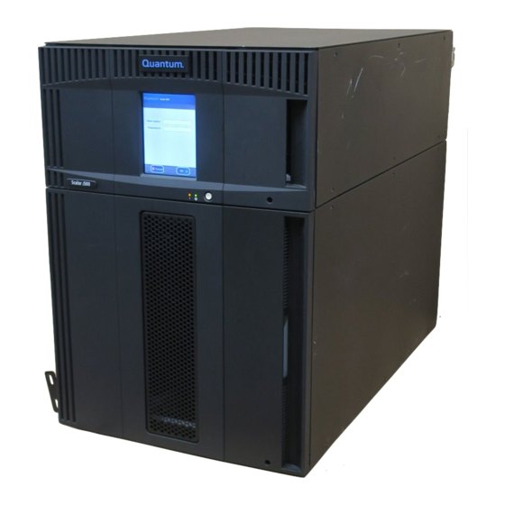
Page 25: Figure 1 5U Library Configuration (Standalone Control Module)
Control Module) Scalar i500 User’s Guide The 5U, 14U, and 23U libraries are the base Scalar i500 systems. By adding 9U expansion modules, you can upgrade a base system to: • A 32U library, consisting of one 5U control module and three 9U expansion modules •... -
Page 26: Figure 2 14U Library Configuration
Figure 2 14U Library Configuration (5U Control Module Plus One 9U Expansion Module) Scalar i500 User’s Guide Control module Expansion module... -
Page 27: Figure 3 23U Library Configuration
Figure 3 23U Library Configuration (5U Control Module Plus Two 9U Expansion Modules) Scalar i500 User’s Guide 5U control module 9U expansion module 9U expansion module... -
Page 28: Description Intelligent Storage
50% and shorten issue resolution times by 30%. Its Capacity on Demand (COD) scalability lets it grow non-disruptively with users’ data. And the Scalar i500 is designed to integrate easily with disk backup, making it the perfect library for next-generation backup architectures. -
Page 29: Modules
Expansion Modules Scalar i500 User’s Guide Scalar i500 libraries are modular, and you can increase the size at any time. The three base systems for the Scalar i500 library are as follows: • The 5U library, consisting of a control module •... -
Page 30: Stackability
(FC) Input/Output (I/O) blades, which provide FC connections for FC drives in the library. If an expansion module is used only for storage and does not contain tape drives or FC I/O blades, it does not need a separate power supply. All power is derived from the control module. -
Page 31: Front Panel Components
Front Panel Components Figure 5 Front Panel Components Access Door Scalar i500 User’s Guide Figure 5 shows the front panel components of the library. The paragraphs following Figure 5 describe the components in detail. Access door Operator panel I/E station Front power switch The access door allows access to the internal components of the library. -
Page 32: I/E Station
A 9U I/E station has a capacity of 12 cartridges within two removable magazines. The I/E stations can also be configured as storage as well as become part of a logical division of library resources known as a partition. The I/E station is shared among all partitions, but the I/E station slots are owned by one partition at a time. -
Page 33: Front Power Switch
Front Power Switch Back Panel Components Scalar i500 User’s Guide through a remote web client. For more information on the library user interfaces, see Chapter 2, Understanding the User Turning off the front power switch turns off the robot and operator panel, but power still runs to the power supplies. -
Page 34: Rear Power Switches
Figure 6 Back Panel Components Rear Power Switches Scalar i500 User’s Guide Library control blade (LCB) FC I/O blade (optional) FC I/O fan blades (required with FC I/O blades) Rear power switch Power supplies Upper and lower Ethernet ports on expansion module Rear power switches are located on each power supply. -
Page 35: Power System
Power System Scalar i500 User’s Guide Turn off the rear power switch whenever you are servicing Warning: the library. In the event of danger to personnel or property, immediately turn off the rear power switch and remove all power cords. -
Page 36: Figure 7 Power Supply Leds
Figure 7 Power Supply LEDs Scalar i500 User’s Guide The power supply has three light-emitting diodes (LEDs) that provide status information. These LED status indicators are green and blue in color. • represents AC OK or DC OK. Green •... -
Page 37: Library Control Blade
Library Control Blade Scalar i500 User’s Guide The library control blade (LCB) manages the entire library, including the operator panel and picker assembly, and is responsible for running system tests to ensure that the library is functioning properly. The LCB also provides internal communication to Fibre Channel (FC) I/O blade slots. -
Page 38: Fibre-Channel Input/Output Blades
Figure 8 Library Control Blade Fibre-Channel Input/Output Blades Scalar i500 User’s Guide LEDs (blue, amber, green) Gigabit Ethernet (external network) port Ethernet I/O blade control ports (inactive if FC I/O blades are not installed) Service Ethernet port Service serial port Expansion modules support optional Fibre Channel (FC) Input/Output (I/O) blades that provide connections for FC tape drives in the library. - Page 39 Scalar i500 User’s Guide Each FC I/O blade has six auto-negotiating, 4 Gb/s FC ports and backplane connections. The FC I/O blade provides two host communication ports and four connection ports to FC drives. Each FC I/O blade is cooled by a fan blade that is installed next to the FC I/O blade in the expansion module.
-
Page 40: Figure 9 Fc I/O Blade
Figure 9 FC I/O Blade Scalar i500 User’s Guide FC ports to host(s) FC ports to drive(s) LEDs (blue, amber, green) Each FC I/O blade is cooled by a fan blade that is installed next to the FC I/O blade in the expansion module. For information on installing the fan... -
Page 41: Robotic System And Barcode Scanner
LED (amber) The robotic system identifies and moves the cartridges between the storage slots, tape drives, and the I/E station. The robotic arm (picker) has picker fingers that enable it to grab tape cartridges and move them into positions along X, Y, and Z motion coordinates. The robotic system and the barcode scanner work together to identify the locations of resources within the library. -
Page 42: Chapter 1 Description Tape Drive Support
• Expansion modules can hold a maximum of four tape drives. Please see Supported Components and media supported by the Scalar i500 library. The library supports mixing different tape drive types within the library and within partitions. For information on how to do this, see With Partitions on page 61. -
Page 43: Library Features
For information on adding tape drives, see page 303. This section describes several features of Scalar i500 libraries. The operator panel is located on the front door of the control module and allows you to work locally on the library via the user interface. The web client allows you to view and perform library functions from remote sites and is accessible through a browser. -
Page 44: Chapter 1 Description Licensable Features
FC I/O blades. For more information, see page 78. Scalar i500 tape libraries support WORM (write once, read many) technology in LTO-3 and LTO-4 tape drives. WORM allows non- rewriteable and non-erasable data to be written and provides extra data security by prohibiting accidental data erasure. -
Page 45: Capacity On Demand (Cod)
Capacity on Demand (COD) Scalar i500 User’s Guide All Scalar i500 library configurations ship with the purchased number of slots pre-activated. The number of available pre-activated slots begins at 41 for all library configurations and increases in 46-slot increments to a maximum of 409 slots in the 41U library configuration. -
Page 46: Quantum Encryption Key Manager (Q-Ekm)
87, 133 87, 133, 179, 225 Quantum Encryption Key Manager (Q-EKM) is a Java software program that generates, protects, stores, and manages encryption keys. These keys are used by the IBM LTO-4 tape drive to encrypt information being written to, and decrypt information being read from, tape media. Q-EKM is installed on a server or servers. -
Page 47: Advanced Reporting
Maximum Number of Drives licensed for Q-EKM Advanced Reporting Scalar i500 User’s Guide The Q-EKM license corresponds to the size of your library. If you purchase Q-EKM for a particular size library and later expand the library, you must purchase an additional Q-EKM license at that time. Your new license key contains the entire license corresponding to your expanded library size. -
Page 48: Chapter 2 Understanding The User Interface
Understanding the User Interface Scalar i500 User’s Guide The user interface of Scalar i500 libraries is available in two formats: the operator panel and the web client. Operations on the library can be performed locally on the control module using the operator panel or remotely on your computer using the web client. -
Page 49: Common User Interface Elements
Common User Interface Elements Scalar i500 User’s Guide The user interface consists of the following areas: • — appears on every screen and contains the company logo, Header product name, and the three main navigation buttons. The main navigation buttons are: •... -
Page 50: Figure 11 Operator Panel User Interface
Chapter 2 Understanding the User Interface Common User Interface Elements Figure 11 Operator Panel User Interface Figure 12 Web Client User Interface Scalar i500 User’s Guide... -
Page 51: System Summary And Subsystem Status
System Summary and Subsystem Status Scalar i500 User’s Guide You can quickly gauge the health of the library by observing the color of the three subsystem status buttons located at the bottom of the home page. These buttons provide quick access to information about the “health”... -
Page 52: Home Page
You can use the Capacity View to see a quick summary of the capacity of the library. You can also see which partitions are online (in the Storage Slots section). The current user’s login privileges determine the information that is displayed in the Capacity View. -
Page 53: Operator Panel
Operator Panel Operator Panel Keypads Web Client Scalar i500 User’s Guide including the order in which the modules are stacked. You will find the same navigation buttons on the Library View as on the Capacity View. The operator panel is physically attached to the front door of the control module. -
Page 54: Chapter 2 Understanding The User Interface Menu Trees
Menu Trees Scalar i500 User’s Guide The following menus organize operations and commands into logical groupings: • The menu consists of commands that users with administrative Setup privileges can use to set up and configure various aspects of the library, including partitions, I/E station slots, cleaning slots, control paths, network settings, drive settings, users, notifications, date and time, licenses, FC I/O blades, library registration, and e-mail. -
Page 55: Table 3 Web Client Menus
Setup Wizard Partitions Cleaning Slots I/E Station Slots Drive Settings Control Path License Notification >Setup >E-mail Account >Contact Information Scalar i500 User’s Guide Operations Menu Tools Menu Media All RAS Tickets >Move >Import >Export Cleaning Media Capture Snapshot >Import >Export... - Page 56 >Data Path Conditioning >Blade Control Encryption >System Configuration >Partition Configuration Date & Time Register Library Administrative users only. Scalar i500 User’s Guide Operations Menu Tools Menu IO Blade Info IO Blade Port Info Update Library Firmware Diagnostics Available only when the library contains I/O blades.
-
Page 57: Table 4 Operator Panel Menus
>Fibre >SCSI > SAS Notification >Email Alerts >Email Account >Customer Contact Licenses Date and Time Scalar i500 User’s Guide Operations Menu Move Media Import Media Export Media Import Cleaning Media Export Cleaning Media Change Partition Mode Tools Menu All RAS Tickets... - Page 58 IO Blades >Port Configuration >Channel Zoning >Host Mapping >Host Management >Host Port Failover >Data Path Conditioning >Blade Control Scalar i500 User’s Guide Operations Menu Load Drive Unload Drive Change Drive Mode Tools Menu Internal Network System Settings >User session timeout (minutes) >Touch screen audio...
-
Page 59: User Privileges
See Working With User Accounts setting user privilege levels. Three types of users are defined in Scalar i500 libraries: • have access to the entire physical library and all Administrative users of its partitions. - Page 60 If you misplace the password for the default administrative account, contact Quantum Technical Support. For contact information, see Getting More Information or Help •...
-
Page 61: User Access
User Access Scalar i500 User’s Guide • When a service user logs in, all other active users are automatically logged out. • For security purposes, an administrative user can prevent a service user from logging on to the library remotely, from either the web client or over the Ethernet service port. -
Page 62: Chapter 3 Configuring Your Library
About the Setup Wizard Scalar i500 User’s Guide Configuring Your Library Once you have installed the hardware as described in the Getting Started Guide, you are ready to configure your library’s settings. A Setup Wizard helps you get started configuring your library, and menu commands on both the operator panel and the web client allow you to reconfigure your library at any time. -
Page 63: Using The Default Administrative User Account
You can, however, change the password. If you misplace the password for the default administrative Note: account, contact Quantum Technical Support. For contact information, see Getting More Information or Help The Setup Wizard is an aid to assist you with the initial configuration of the library. -
Page 64: Using The Setup Wizard
Using the Setup Wizard Scalar i500 User’s Guide appropriate screens on both the operator panel and the web client are given for each task. For the operator panel, the paths refer to the navigation tabs at the top of the home page. For the web client, the paths refer to the menus. - Page 65 Scalar i500 User’s Guide • If you are using IPv6: select the Enable IPv6 IPv6 but you will not be prompted to configure IPv6 settings here. Continue with the Setup Wizard screens. Then, when you are finished using the Setup Wizard, configure the IPv6 network settings by going to Setup >...
-
Page 66: Default Configuration Settings
Default Configuration Settings Setup Wizard Tasks Scalar i500 User’s Guide • You can return to the Setup Wizard • Any administrative users you create will also be able to use the Setup Wizard from the web client as well as commands to reconfigure the library. - Page 67 Scalar i500 User’s Guide • Hardware Installation (operator panel) — Reminds you to install tape drives and the Ethernet cable. • Setting the Date, Time, and Time Zone client) — Allows you to set the date and time on your library.
-
Page 68: Logging On To The Web Client
Logging On to the Web Client Managing the Network Scalar i500 User’s Guide The paths to open the appropriate screens are as follows: • From the web client, select • From the operator panel, the power-on of library. Once you have configured network settings on the operator panel, you can log on to the library’s web client. -
Page 69: Modifying Network Settings
Modifying Network Settings Scalar i500 User’s Guide Security settings must be enabled to allow SNMP, SMI-S, Caution: and IP address access to the library network. After applying any of the settings on the Network Management screens, verify the settings on the Security Settings screen. - Page 70 Scalar i500 User’s Guide Details on network settings include: • is the network name you want to assign to the library. Library Name The library name is limited to 12 lowercase alphanumeric characters and dashes (-). • defaults to enabled. When DHCP is enabled, the library obtains DHCP an IP address automatically.
-
Page 71: Enabling Ssl
Enabling SSL Scalar i500 User’s Guide Modifying network settings will modify network Caution: connectivity parameters, requiring remote communication configuration changes. Your current web client browser session might become invalid, requiring you to close your current browser session. Access the web client using the new network configuration settings and log in again. -
Page 72: Configuring Snmp Settings On The Library
Configuring SNMP Settings on the Library Scalar i500 User’s Guide Before enabling SSL settings, make sure you enter a name for Note: the library in the Library Name text box when configuring network settings ( Setup > Network Mgmt panel). After enabling SSL settings, use that library name to access the library. - Page 73 Scalar i500 User’s Guide • Modify the default Read SNMP community string, which is used as a password to authenticate GET and GET-NEXT SNMP v1 and SNMP v2c messages exchanged between the library and a remote management application. For more information, see Read SNMP Community String •...
- Page 74 Scalar i500 User’s Guide • — Adds the IP address and port number of the external Create application to the list of registered addresses that will be sent SNMP traps. • — Allows you to delete a selected IP address and port number.
- Page 75 Scalar i500 User’s Guide The paths to open the appropriate screens are as follows: • From the web client select • From the operator panel select V1/V2 Modifying the Read SNMP Community String Administrative users can modify the Read SNMP community string. The...
-
Page 76: Working With Partitions
Getting More Information or Help information on integrating MIBs with an SNMP management application, contact your network management application vendor. The SNMP MIB is also available on the Scalar i500 Note: Documentation and Training CD. You cannot download the SNMP MIB from the operator panel. The path to open the appropriate screen is as follows: •... -
Page 77: Table 5 Number Of Partitions Supported
Table 5 Number of Partitions Supported Scalar i500 User’s Guide At any time after the initial configuration of the library, administrative users can create, modify, and delete partitions by selecting on the web client, or create and delete partitions by selecting Partitions on the operator panel. -
Page 78: Automatically Creating Partitions
Automatically Creating Partitions Scalar i500 User’s Guide Details on partitions include: • Administrative users can create, modify, delete, and control access to all partitions. Users can be given access to only certain partitions and denied access to others. • Partition names are limited to 12 lower-case alphanumeric characters and underscores (_). -
Page 79: Manually Creating Partitions
Manually Creating Partitions Scalar i500 User’s Guide The default number of partitions created is the number of distinct tape drive interface/vendor combinations of the tape drives that are not currently assigned to a partition. For example: • If your library contained two tape drives, a FC IBM LTO-3 and a FC IBM LTO-4, one partition would be created since they are the same interface type and vendor. - Page 80 Scalar i500 User’s Guide or delete an existing partition to free up resources. For more information, Modifying Partitions on page 66 and When you manually create partitions, the library creates control paths. Working With Control Paths default control paths and how to change them.
-
Page 81: Modifying Partitions
Modifying Partitions Scalar i500 User’s Guide • — Five to 14 character barcode number followed by Media ID First media ID, for example, “XXXXXXXXXXXXXXL4”. The media ID is reported to the host first. • — (default) Five to 16 characters total, including a Standard barcode number and optional media ID. -
Page 82: Deleting Partitions
Deleting Partitions Scalar i500 User’s Guide When modifying a partition, you may need to provide the following information: • — the type of library that the partition is Emulation Type emulating.See Manually Creating Partitions descriptions of available options. • — limited to a maximum of 12 lower-case Partition Name alphanumeric characters and underscores (_). -
Page 83: Deleting Partitions Before Removing Or Replacing Modules
Deleting Partitions Before Removing or Replacing Modules Scalar i500 User’s Guide Details about deleting partitions include the following: • After a partition is deleted, its resources (for example, tape drives and slots) become available and can be reassigned to new or existing partitions. -
Page 84: Changing Partition Access
Changing Partition Access Changing Partition Modes Scalar i500 User’s Guide • Using your I/E station, export all the tape cartridges from your library. See Exporting Media • Reduce the number of cleaning slots in the library to 0. You can designate new cleaning slots after the module has been removed or replaced. -
Page 85: Disabling/Enabling Manual Cartridge Assignment
Disabling/Enabling Manual Cartridge Assignment Scalar i500 User’s Guide There are two partition modes: online and offline. • — Normal operating condition for the partition. In this mode, Online all host application commands are processed. • — Move commands are not processed. If the partition is taken Offline offline, the physical library and other partitions are not affected. -
Page 86: Configuring Cleaning Slots
Configuring Cleaning Slots Scalar i500 User’s Guide When manual cartridge assignment is disabled, the not appear on the operator panel, and the cartridges in the I/E station are visible to all partitions, as well as the system partition, and can be used by any partition. - Page 87 Scalar i500 User’s Guide you to enter the number of cleaning slots (if any) you want to designate for your library. You can also access the screens directly on the operator panel and web client. default configuration settings include zero dedicated Setup Wizard cleaning slots.
-
Page 88: Configuring I/E Station Slots
If the library consists of a control module, all six I/E station slots must be configured either as storage or as I/E station slots. A 14U library consists of a control module (with six I/E station slots) and an expansion module (with 12 I/E station slots). -
Page 89: Table 6 Number Of I/E Station Slots Available
• If you increase the size of your library by adding expansion modules, the I/E stations in the new modules will be storage slots by default. You can select to reconfigure these slots as I/E slots. -
Page 90: Configuring Zero I/E Station Slots
I/E station may be configured automatically as storage. • If the I/E station is configured as data storage slots, its door is always locked. For information on unlocking I/E stations, see Unlocking the I/E Stations •... -
Page 91: Setting Tape Drive Parameters
Setting Tape Drive Parameters Scalar i500 User’s Guide This operation cannot be performed concurrently by multiple Note: administrative users logged in from different locations. You can access the screen, but you cannot apply changes while another administrative user is performing the same operation. - Page 92 Scalar i500 User’s Guide For FC tape drives: • The loop ID can be set to a value from 0 to 125. A unique loop ID is selected by default for all FC tape drives installed in the library. For example, the tape drive installed in the top drive bay of a control module is assigned a default loop ID of 61.
-
Page 93: Working With Control Paths
One or more No FC tape FC I/O blades drives Scalar i500 User’s Guide The control path tape drive is used to connect partition to a host application. The library automatically assigns control paths when you set up partitions. You can modify the control path at any time. - Page 94 Scalar i500 User’s Guide Only one tape drive in a partition can be selected as the control path per partition. In the event that the control path connection to the host application fails, you can select a new control path for the partition.
-
Page 95: Adding Or Upgrading Licensable Features
Quantum issues you a license key certificate. The license key certificate contains an authorization code that enables you to retrieve your license key from the Quantum web site. Once you install the license key on the library, the feature becomes available. -
Page 96: About License Keys
Web sites listed above. In some cases, factory installed license keys will not be listed on the Web site and you will need to contact Quantum for a replacement. If you cannot retrieve your license keys or need assistance, contact Quantum. -
Page 97: Obtaining A License Key
1 Contact your Quantum technical sales representative to submit your order for the feature or upgrade. For contact information, see More Information or Help 2 Upon receipt of your order, Quantum will ship you a license key certificate containing your authorization code. Note: If you order more than 46 COD slots: COD licenses come in 46-slot increments. -
Page 98: Applying A License Key
Applying a License Key Scalar i500 User’s Guide 6 Click Submit If you have entered a valid serial number, the website displays existing license keys for this feature. Exception: If the license was applied at the factory, the word “... -
Page 99: Configuring Quantum Encryption Key Manager (Q-Ekm)
LTO-4 drive-based data encryption process. Library-managed encryption is an optional, licensed feature that must be enabled from the Scalar i500 library in order to begin encrypting data using the LTO-4 tape drive encryption capabilities. -
Page 100: Step 4: Configure Q-Ekm Server Tcp/Ip Addresses
Q-EKM server to match or Q-EKM will not work properly. See the Quantum Encryption Key Manager User’s Guide for information on setting the port number on the Q-EKM server. -
Page 101: Step 5: Configure Partition Encryption
7 Click Apply Encryption on the Scalar i500 tape library is enabled by partition only. You cannot select individual tape drives for encryption; you must select an entire partition to be encrypted. If you encrypt a partition, all Q-EKM-supported tape drives in that partition are enabled for encryption. - Page 102 Scalar i500 User’s Guide Configuring Quantum Encryption Key Manager (Q-EKM) 3 Select an encryption method from the drop-down menu for each partition. (For tape drives that support encryption, the default is Allow Application Managed. encryption-capable tape drives and media in that partition.
-
Page 103: Setting Customer Contact Information
Setting Customer Contact Information Configuring the Library E-mail Account Scalar i500 User’s Guide Administrative users can use the web client to enter contact information into the library for the person who is the primary customer contact for the library. Keep this information current to expedite the Service process. - Page 104 Scalar i500 User’s Guide Setup > Notification > E-mail Account options: • includes the IP address or host name of the SMTP SMTP Server server. IP addresses must be entered in dot notation (for example, 192.168.0.1) and cannot exceed 255.
-
Page 105: Working With E-Mail Notifications
Working With E-mail Notifications Scalar i500 User’s Guide The paths to open the appropriate screens are as follows: • From the web client, select • From the operator panel, select The library can be configured to automatically send e-mail notifications to specified e-mail addresses whenever an issue of a particular severity level occurs with one of its components. -
Page 106: Creating E-Mail Notifications
Creating E-mail Notifications Modifying E-mail Notifications Scalar i500 User’s Guide You can configure e-mail notifications from the web client only, but you can view them from the operator panel. The paths to open the appropriate screens are as follows: • From the web client, select •... -
Page 107: Deleting E-Mail Notifications
Deleting E-mail Notifications Working With User Accounts Local Authentication vs. Remote Authentication Scalar i500 User’s Guide The default techsup@quantum.com Note: can be modified, but not deleted. The e-mail address, techsup@quantum.com, cannot be modified. The path to open the appropriate screen is as follows: •... -
Page 108: About Local User Accounts
The default administrative user account is used to perform the initial configuration of the library. If you misplace the password for the default administrative account, contact Quantum Technical Support. For contact information, see Getting More Information or Help... -
Page 109: Modifying Local User Accounts
Modifying Local User Accounts Scalar i500 User’s Guide To create local user accounts, you need to provide information for the following fields: • — the login name of the user account you are creating. User Name User names are limited to 1–12 lower-case letters, numbers, and underscores (_). -
Page 110: Deleting Local User Accounts
Deleting Local User Accounts Configuring LDAP Scalar i500 User’s Guide Administrative users can delete other local administrative user and user accounts when they are no longer needed. The default administrative user account cannot be deleted. Note: The paths to open the appropriate screens are as follows: •... - Page 111 Scalar i500 User’s Guide • The library supports user account information in the schema defined by RFC 2307. User password schemes must be encrypted using UNIX crypt. In addition, user names (uid) and passwords (userPassword) must be created using lowercase characters to be compatible with the library.
-
Page 112: Configuring Kerberos
Configuring Kerberos Scalar i500 User’s Guide • — the name of the group you want to associate Library user group with the library. This group is equivalent to the local user privilege level. Any member of this group can manage this library. See Privileges on page 44 for more information on user privilege levels. - Page 113 Scalar i500 User’s Guide Fill in the following Kerberos fields in addition to all the LDAP fields: • — The Kerberos realm name, typed in all uppercase letters. Realm Usually the realm name is the DNS domain name. • — The server on which Kerberos is installed.
- Page 114 Scalar i500 User’s Guide 6 At the command prompt, create the keytab file for the SPN. Use one of the following formats: • For Windows 2003: ktpass -out library.keytab -princ library/<fqdn of library>@<realm> +rndPass -ptype KRB5_NT_SRV_HST -crypto RC4-HMAC-NT - mapUser <realm>/computers/<computer account>...
-
Page 115: Setting The Date, Time, And Time Zone
Setting the Date, Time, and Time Zone Setting the Date and Time Manually Scalar i500 User’s Guide Administrative users can either set the library date, time, and time zone settings manually or configure the Network Time Protocol (NTP). The following operations should not be performed... -
Page 116: Setting The Date And Time Using The Network Time Protocol
Using the Network Time Protocol Setting the Time Zone Scalar i500 User’s Guide The library supports the Network Time Protocol (NTP). NTP allows you to synchronize the library date and time with other components in your IT infrastructure. Administrative users can either modify the date and time zone settings manually or configure NTP. -
Page 117: Setting Daylight Saving Time
Setting Daylight Saving Time Working With FC I/O Blades Scalar i500 User’s Guide If you selected your time zone from the drop-down list (see Time Zone), the library automatically adjusts for daylight saving time. There is no need to manually reset the clock for time changes. -
Page 118: Configuring Fc I/O Blade Ports
Configuring FC I/O Blade Ports Scalar i500 User’s Guide The topics in this chapter cover configuring FC I/O blades. For additional information on FC I/O blades, see: • Fibre-Channel Input/Output Blades • Controlling FC I/O Blade Power • Viewing FC I/O Blade Information •... -
Page 119: Fc I/O Blade Internal Virtual Port For Medium Changers
I/O blade can access all medium changer devices, except those that are defined in association with drive-based access (also known as “LUN-1”). The Scalar i500 library can have up to 18 partitions. These internal virtual ports are not configurable via channel zoning; thus, all medium changer devices are accessible via ports 1 and 2 of each FC I/O blade present within the library. -
Page 120: Configuring Fc I/O Blade Channel Zoning
Configuring FC I/O Blade Channel Zoning Scalar i500 User’s Guide When FC I/O blades are installed in the library, administrative users can configure channel zoning for selected I/O blades. Channel zoning, also called port zoning, configures access to an entire FC and all the LUNs on that channel for the exclusive use of a host or group of hosts on a single port. -
Page 121: Managing Fc Hosts And Host Mapping
• From the web client, select • From the operator panel, select An FC host is the main processing server on a storage area network (SAN) that receives data and initiates communication with other devices. When FC I/O blades are installed in the library, administrative users can access, add, modify, and delete FC hosts and also configure FC host mapping. -
Page 122: Enabling/Disabling Fc Host Mapping
Enabling/Disabling FC Host Mapping Viewing FC Host Information Scalar i500 User’s Guide On the operator panel, the host management screens ( Note: I/O Blades > Host Management mapping is enabled. If both channel zoning and host mapping are enabled, the... -
Page 123: Creating, Modifying, And Deleting An Fc Host Connection
Creating, Modifying, and Deleting an FC Host Connection Scalar i500 User’s Guide The paths to open the appropriate screens are as follows: • From the operator panel, select • From the web client, select Administrative users can manually create a connection to an FC host if the host was not already connected to the library when it was turned on. -
Page 124: Host Mapping - Overview
Host Mapping - Overview Scalar i500 User’s Guide Modifying an FC Host Connection For each FC host connection you want to modify, you can set the following parameters: • — the host device name. Host Name • — the host port number. -
Page 125: Host Mapping Vs. Channel Zoning
Host Mapping Vs. Channel Zoning Scalar i500 User’s Guide to which it is attached. These LUNs can be re-mapped to new LUNs for presentation via ports 1 and 2. Further, custom LUN maps can be simultaneously defined for individual hosts. -
Page 126: Configuring Host Mapping
Configuring Host Mapping Scalar i500 User’s Guide access for all the LUNs, channel zoning might not be necessary or desired. On the operator panel, the host mapping screens ( Note: Blades > Host Mapping mapping is enabled. See Mapping on page 107. - Page 127 Scalar i500 User’s Guide • — Name of the device. Product • — Current logical unit number (LUN) assignment. Assign a new LUN number for the device. The operator panel host mapping configuration screens Note: show less information about each device; however, you still select the host and device(s) and configure the LUN number(s(.)
-
Page 128: Configuring Fc Host Port Failover
Configuring FC Host Port Failover Scalar i500 User’s Guide When I/O blades are installed in the library, administrative users can enable and configure the optional FC host port failover feature. This feature is disabled by default. You can configure the FC host port failover feature so that a “standby”... -
Page 129: Repairing And Enabling A Failed Target Port
Repairing and Enabling a Failed Target Port Scalar i500 User’s Guide Details on configuring host port failover include: • The Setup - Host Port Failover found in the library. I/O blades are listed by the following: location in the library, WWNN (web client only), and status/state. You can select the I/O blade you want to configure for host port failover and proceed to the next screen. - Page 130 Scalar i500 User’s Guide • The Setup - Host Port Failover found in the library. I/O blades are listed by the following: location in the library, WWNN (web client only), and status/state. You can select the I/O blade that had a failed target port and proceed to the next screen.
-
Page 131: Working With Data Path Conditioning
Working With Data Path Conditioning Scalar i500 User’s Guide When I/O blades are installed, administrative users can configure data path conditioning, an automatic means of verifying, monitoring, and protecting data path integrity between FC I/O blades and FC tape drives. -
Page 132: Configuring Library Security Settings
Configuring Library Security Settings Scalar i500 User’s Guide The paths to open the appropriate screens are as follows: • From the web client, select Conditioning • From the operator panel, select Conditioning Administrative users can use the operator panel to change the following security features: •... -
Page 133: Configuring The Internal Network
Configuring the Internal Network Configuring System Settings Scalar i500 User’s Guide Use the Internal Network Configuration internal network setting. The default internal network address is 10.10.10.X The library’s internal network enables communication among library components. While rare, it is possible that the default addressing of the internal network could conflict with your network, potentially causing the library to become confused. - Page 134 Scalar i500 User’s Guide • — Allows you to specify whether the library should Unload Assist automatically eject cartridges from tape drives. When the setting is enabled, the library will assist with tape drive unload operations in the event that a tape drive is not unloaded by a host command. When...
-
Page 135: Configuring Operator Panel Display Settings
Configuring Operator Panel Display Settings Scalar i500 User’s Guide • — Allows you to enable Secure Socket Layer (SSL) for Enable SSL secure data transmission between the library and remote clients. This option is disabled by default. • — Allows you to enable or disable support for Enable SNMP V1/V2 Simple Network Management Protocol (SNMP) V1 and V2c. -
Page 136: Registering The Library
Registering the Library Scalar i500 User’s Guide by tapping the up and down arrows. The brightness and contrast to the default settings. You cannot configure the display settings from the web client. The path to open the appropriate screen is as follows: •... -
Page 137: Chapter 4 Running Your Library
Logging In Scalar i500 User’s Guide Running Your Library This chapter explains how to access and operate your library. Most of the library functions described here can be found on the The information in this chapter assumes you are using the web Note: client. -
Page 138: Logging In When Ldap Or Kerberos Is Enabled
94. If you misplace the password for the default administrative Note: account, contact Quantum Technical Support. For contact information, see Getting More Information or Help When LDAP or Kerberos is enabled, the following items in addition to the User Name and Password text boxes: •... -
Page 139: Understanding The Location Coordinates
Understanding the Location Coordinates Figure 13 Library Location Coordinates Scalar i500 User’s Guide This section describes the numbering system used to identify components of the library. The library location coordinates contain the following digits: [Module],[Column],[Slot]. control module and an expansion modules numbered. -
Page 140: Modules
–1. The expansion module stacked directly below module –1 is number –2, and so on. A storage column is a group of slots arranged vertically in the library. Columns are represented by the second digit of a library coordinate. -
Page 141: Fibre Channel I/O Blades
• Import data cartridges into the library • Export data cartridges from the library • Move data cartridges between tape drives, I/E stations, and storage slots within a partition • Import cleaning cartridges into the library (AutoClean is enabled) •... -
Page 142: Importing Media
For more information, see Disabling/Enabling Manual Cartridge Assignment Before importing cartridges, verify that all tape drives are unloaded and that all cartridges are in their appropriate storage slot locations. Doing this will avoid over-loading the library with cartridges. Performing Media Operations... - Page 143 Scalar i500 User’s Guide If you have AutoClean enabled, you can also import cleaning cartridges into the library. For information, see page 138. In addition, you can bulkload cartridges into the library rather than use the I/E station to import media. For information, see Bulkloading on page 129.
-
Page 144: Bulkloading
Bulkloading Scalar i500 User’s Guide 3 Use the screens on either the operator panel or the web Import Media client to import the cartridges into the partition. Follow the on-screen prompts, or see the library’s online Help for step-by-step procedures. - Page 145 When all I/E station slots are configured as storage, the I/E station door is always locked. You will not be able to open the main access door to bulkload tape cartridges into the library without first unlocking the I/E station door.
-
Page 146: Moving Media
When bulkloading the library, do not insert storage or cleaning tapes into the bottom row of the lowest module in the library configuration. -
Page 147: Exporting Media
The Export Media operation enables you to export data cartridges from storage slots to empty I/E station slots for removal from the library. If your library has zero I/E station slots, you cannot import or Note: export media. - Page 148 Scalar i500 User’s Guide Some host applications may fail import/export operations Caution: when the I/E station contains cartridges that are assigned to another partition. Move cartridges from the I/E station as soon as possible to avoid possible conflicts with the other partitions.
-
Page 149: Loading Tape Drives
The Load Drive operation enables you to load a cartridge from a storage slot into a tape drive. The storage slot and tape drive must be assigned to the same partition. This topic focuses on using the library user interface, not the host application, to load tape drives. -
Page 150: Unloading Tape Drives
The Unload Drive operation allows you to unload a cartridge from a tape drive to a storage slot. The storage slot and tape drive must be assigned to the same partition. This topic focuses on using the library user interface, not the host application, to unload tape drives. -
Page 151: Changing The Tape Drive Mode
Changing the Tape Drive Mode Scalar i500 User’s Guide You can take the tape drive online or offline. When the tape drive mode is online, the tape drive is available for use. When the tape drive mode is offline, the tape drive is offline to the host application and is not available for use. -
Page 152: Chapter 4 Running Your Library About Cleaning Tape Drives
About Cleaning Tape Drives Scalar i500 User’s Guide Library tape drives require occasional cleaning. Cleaning cartridges are used to remove accumulated residue from each tape drive’s read/write head. The library supports two methods for cleaning tape drives with cleaning cartridges: AutoClean and Manual. -
Page 153: Enabling Autoclean
Enabling AutoClean Importing Cleaning Media Scalar i500 User’s Guide Cleaning slots are not visible to the host application. To choose Note: host-based cleaning, do not configure any cleaning slots, and configure your host application to manage cleaning tape drives. Configuring cleaning slots on the library may affect the host application. - Page 154 Scalar i500 User’s Guide Some host applications may fail import/export operations Caution: when the I/E station contains cartridges that are assigned to another partition. Move cartridges from the I/E station as soon as possible to avoid possible conflicts with the other partitions.
-
Page 155: Exporting Cleaning Media
Exporting Cleaning Media Scalar i500 User’s Guide You need to provide the following information in the screens to import media: Media • — the cleaning cartridges that you want to import. Media The screen includes information about the number of empty cleaning slots in the library. -
Page 156: Manually Cleaning Tape Drives
Manually Cleaning Tape Drives Scalar i500 User’s Guide Details on exporting cleaning cartridges include: • You must have access to the library’s I/E station and the operator panel to export cleaning cartridges. • You can only export cartridges if empty I/E station slots are available. -
Page 157: Chapter 4 Running Your Library About Tape Drive Operations
About Tape Drive Operations Scalar i500 User’s Guide topmost I/E station slot. If two or more cleaning slots are configured and have cleaning tapes in them, the library chooses which cleaning tape to use. If you have zero cleaning slots configured, or if you are using the operator panel, you must use a cleaning tape in the topmost I/E station slot. -
Page 158: Chapter 4 Running Your Library
Administrative users can use this operation to lock or unlock the doors for all I/E stations that are configured as I/E station slots. If all I/E station slots are configured as storage, this operation unlocks the control module I/E station only. -
Page 159: Chapter 4 Running Your Library Controlling Fc I/O Blade Power
• A user has requested that the I/E station door be locked. • If the I/E station slots are configured as storage slots, the door is always locked. When all I/E station slots are configured as storage slots, you can use the Locking and Unlocking I/E station operation to unlock the I/E station in the control module. -
Page 160: Shutting Down Or Restarting The Library
Shutting Down or Restarting the Library Scalar i500 User’s Guide On the operator panel, select the option you want: • Power Cycle Blade • Power On Blade • Power Off Blade This operation should not be performed concurrently by Note: multiple administrative users logged in from different locations. -
Page 161: Chapter 4 Running Your Library Shutting Down Or Restarting The Library
Scalar i500 User’s Guide To turn the library back on, turn on the power switch on each power supply, press the front power switch again, and then follow the login procedure. If you do not perform a shutdown before you physically... -
Page 162: Chapter 5 Getting Information
Viewing Information About the Scalar i500 Scalar i500 User’s Guide Getting Information This chapter describes how to find information about your library. From the operator panel, you can find system information in the screen ( Scalar i500 Tools > About Library... -
Page 163: Viewing System Information
Library Partitions encryption method, number of slots, number of media, and number of tape drives. Viewing System Information screen provides the following About screen, you can also navigate to other Reports > About > Scalar i500 Tools > About Library... -
Page 164: Chapter 5 Getting Information Viewing The Library Configuration
Viewing the Library Configuration Scalar i500 User’s Guide • location coordinates, vendor name, model, type, Tape drives — physical serial number (P-SN), logical serial number (L-SN), firmware level, sled boot version, sled application version, encryption method, and whether the tape drive is connected to an I/O blade. -
Page 165: Chapter 5 Getting Information Viewing Network Settings
Viewing Network Settings Scalar i500 User’s Guide • — name, online status, emulation type, barcode policy, Partitions number of total tape drives in the partition, number of active tape drives partition, total media, mounted media, total slots, full slots, total I/E stations, full I/E stations, and encryption method of each partition. -
Page 166: Chapter 5 Getting Information Viewing Logged-In Users
Viewing Logged-in Users Viewing Slot Information Scalar i500 User’s Guide report contains information about the users that are User Login currently logged into the library. The report contains the following information: • — name of logged-in user. User name •... -
Page 167: Chapter 5 Getting Information Viewing, Saving, And E-Mailing Library Logs
Viewing, Saving, and E-mailing Library Logs Scalar i500 User’s Guide • — element address of the slot. Element Address • — the encryption state of the media in the slot. In order for Encryption the library to know the encryption state, the tape must have been placed into an encryption-capable tape drive in the library. - Page 168 The comma-separated values (csv) file provides the following information for each slot: Date and Time, Slot Type (Picker, Drive, Storage, or IE), Object Present? (Y, N), Location Coordinates, X Position, Y Position, Angle Position, X Calibration Offset, Y Calibration Offset.
-
Page 169: Chapter 5 Getting Information Using Advanced Reporting
Using Advanced Reporting Scalar i500 User’s Guide Advanced Reporting provides the following reports that you can configure for viewing and analysis: • Drive Resource Utilization Report information, showing you which tape drives are working at optimum capacity and which are under-utilized. This can help you allocate your tape drive resources properly. -
Page 170: Configuring The Drive Resource Utilization Report
Configuring the Drive Resource Utilization Report Scalar i500 User’s Guide • Information about a tape drive, cartridge, or operation is not recorded in the Drive Resource Utilization log file until after a tape cartridge has been mounted (loaded) and unmounted (unloaded) from the tape drive. - Page 171 Scalar i500 User’s Guide • Attribute — Specifies which values are included in the report. Select one of the following: • Data Written/Read (default) — the amount of data written to and read from each tape drive, shown separately in the chart.
-
Page 172: Configuring The Media Integrity Analysis Report
Configuring the Media Integrity Analysis Report Scalar i500 User’s Guide • Selected Drive by Coordinate — The report chart is based on an individual tape drive location in the library. If more than one tape drive resided in that location during the selected range, then the attribute values for all the tape drives that resided in that location are combined in the chart. - Page 173 Scalar i500 User’s Guide • Attributes—Specifies which values are included in the report, and how they are combined. Select in any combination, including all (default) and none. If you select no attributes, the chart displays the TapeAlert count for the selected Grouping.
-
Page 174: Using Advanced Reporting Templates
Reporting Templates Loading and Reloading Advanced Reporting Data Scalar i500 User’s Guide If you want to use the same configuration repeatedly, you can save it as a template. You can save up to 20 templates for each type of advanced report. -
Page 175: Deleting Advanced Reporting Data
Figure 14 Report Data Buttons Saving and E-mailing Advanced Reporting Data Scalar i500 User’s Guide You can see how many records were loaded from the log files for this report by looking at the Report Data section of the report configuration page. -
Page 176: Figure 15 Saving And E-Mailing The Report Data
Figure 15 Saving and E- mailing the Report Data Viewing FC I/O Blade Information Scalar i500 User’s Guide 4 To e-mail the report data as a .csv file, type the name of a recipient in the empty field next to the Administrative users can view information about all the FC I/O blades installed in the library. -
Page 177: Chapter 5 Getting Information Viewing Fc I/O Blade Port Information
Viewing FC I/O Blade Port Information Scalar i500 User’s Guide Administrative users can view information about all the FC I/O blades installed in the library. The Tools - Blade Port Information following port information for each FC I/O blade: •... -
Page 178: Chapter 6 Updating Library And Tape Drive Firmware
(including drive sled firmware) and tape drive firmware. There may be times when you will need to upgrade your library and tape drive firmware as directed by Quantum Technical Support. You can also regularly monitor the Quantum Service & Support website at www.quantum.com/support need to make sure that the firmware you download is compatible with your library and tape drives. - Page 179 Scalar i500 User’s Guide firmware comes bundled with tape drive firmware, firmware upgrade instructions, and release notes. Verify with the release notes or Quantum Technical Support that you are updating the library with the correct version of firmware. For technical support contact information, see Getting More Information or Help Library firmware version 200G.GSxxx and 210G.GSxxx (SP1) support...
- Page 180 If you are running firmware version 400G or higher and want Note: to downgrade, the following restrictions apply: • If your library is Quantum branded, you can downgrade to version 400G or higher (there is no lower version of Quantum-branded firmware).
-
Page 181: Updating Tape Drive Firmware
Scalar i500 User’s Guide You can use the web client to upgrade one or more tape drives in your library with an image file downloaded from the Quantum Service & Support website. The web client allows you to upgrade tape drive firmware using a firmware image file. -
Page 182: Chapter 6 Updating Library And Tape Drive Firmware Updating Tape Drive Firmware
FIPS-compliant [for example, PGA1 (77BE)]. If you need to downgrade LTO-4 tape drive firmware from level 82FB or higher to level 77BE or lower, contact Quantum Technical Support for instructions and assistance. Updating Tape Drive Firmware Tools >... -
Page 183: Autoleveling Tape Drive Firmware
Before uploading tape drive firmware, verify with published release notes or Quantum Technical Support that you are uploading the correct version of firmware. For technical support contact information, More Information or Help on page 8. -
Page 184: Deleting Tape Drive Firmware Used In Autoleveling
Deleting Tape Drive Firmware Used in Autoleveling Scalar i500 User’s Guide You cannot upload tape drive firmware from the operator panel. The path to the appropriate screen is as follows: • From the web client, select The library allows you to delete a firmware image file if you no longer want to autolevel tape drive firmware. -
Page 185: Chapter 7 Installing, Removing, And Replacing
Scalar i500 User’s Guide Installing, Removing, and This chapter describes how to add, remove, and replace hardware within your library. Adding, removing, or replacing library components may require you to power off the entire library. There are a few components, however, that you can service without powering off the library, such as replacing tape drives. -
Page 186: Taking The Library Online/Offline
Taking the Library Online/Offline Taking a Library Online Scalar i500 User’s Guide Without tape drives, tape cartridges, or power supplies, a Warning: control module weighs approximately 58 lbs. An expansion module, without tape drives, tape cartridges, or power supplies, exceeds 65 lbs. -
Page 187: Taking A Library Offline
Taking a Library Offline Cabling the Library Connecting Library SCSI Cables to Hosts Scalar i500 User’s Guide 1 Using the library’s operator panel, select ; or, using the web client, select Partition Mode > Change Mode 2 For each partition that you want to take offline, click... -
Page 188: Figure 16 Stand-Alone 5U Control Module Scsi Cabling
Figure 16 Stand-Alone 5U Control Module SCSI Cabling Scalar i500 User’s Guide Ethernet cable to customer network GB Ethernet port SCSI terminator Power supply Rear power switch SCSI cable to host Library control blade Module terminators Cabling the Library... -
Page 189: Figure 17 Multi-Module Scsi Cabling
Figure 17 Multi-Module SCSI Cabling Scalar i500 User’s Guide Module-to-module cable Library control blade GB Ethernet port SCSI terminator Power supply Rear power switch Power cords SCSI cables to host Module terminators 10 Ethernet cable to customer network Cabling the Library... - Page 190 Scalar i500 User’s Guide 1 If your library is 14U or larger, install it in a rack. See Library in a Rack on page 284 for instructions. The instructions include procedures for removing and replacing tape drives. 2 Connect the SCSI cables to the tape drives.
-
Page 191: Connecting Library Fc Cables Directly To Host
Connecting Library FC Cables Directly to Host Scalar i500 User’s Guide 7 Power on the library. a Turn on the rear power switch of each of the power supplies. b Turn on the front power switch. c Power up the host system. -
Page 192: Figure 18 Stand-Alone Control Module Fibre Channel Cabling
Figure 18 Stand-Alone Control Module Fibre Channel Cabling Scalar i500 User’s Guide Ethernet cable to customer network GB Ethernet port Power supply Rear power switch Power cord Fibre cable to host Library control blade (LCB) Module terminators Cabling the Library... -
Page 193: Figure 19 Multi-Module Fibre Channel Cabling
Figure 19 Multi-Module Fibre Channel Cabling Scalar i500 User’s Guide Ethernet cable to network GB Ethernet port Power supply Rear power switch Power cords Fibre cables to host Module terminators Library control blade (LCB) Module-to-module cable Cabling the Library... - Page 194 Scalar i500 User’s Guide All libraries taller than 14U must be installed in a rack Warning: having a main protective earthing (grounding) terminal, and power must be supplied via an industrial plug and socket-outlet and/or an appliance coupler complying with...
-
Page 195: Connecting Library Fc Cables To Fc I/O Blades
Connecting Library FC Cables to FC I/O Blades Scalar i500 User’s Guide If your library configuration consists of a single module, place module terminators in the module’s top and bottom module terminator connectors. b If you need to add expansion modules to the control module, remove the module terminator from the control module terminator connection that is closest to the expansion module. - Page 196 Scalar i500 User’s Guide accessible to defined zone. For information on partitioning, configuring FC I/O blade ports, channel zoning, and host mapping, see Your Library on page 47. Details about cabling FC I/O blades include: • Each expansion module can support up to two FC I/O blades. A maximum of four FC I/O blades can be present in any library configuration.
-
Page 197: Figure 20 Fc I/O Blade
Figure 20 FC I/O Blade Scalar i500 User’s Guide Target ports 1 and 2 to host(s) Initiator ports 3 – 6 to drives LEDs (blue, amber, green) Use the following procedure, along with library that includes FC tape drives that are connected to FC I/O blades. -
Page 198: Figure 21 Fc With I/O Blade Cabling
Chapter 7 Installing, Removing, and Replacing Cabling the Library Figure 21 FC With I/O Blade Cabling Scalar i500 User’s Guide... - Page 199 Scalar i500 User’s Guide Library control blade (LCB) GB Ethernet port Power supplies Power cords Ethernet cables from LCB to expansion module FC cable from FC I/O blade to tape drive Module terminator FC cable to host Module-to-module cable 10 Ethernet cable to network...
- Page 200 Scalar i500 User’s Guide 2 For each FC I/O blade installed in an expansion module, connect the expansion module containing the FC I/O blade(s) to a port in the Ethernet hub on the LCB: Without these Ethernet cables connected, the FC I/O Note: blades will not work.
- Page 201 Scalar i500 User’s Guide 9 Install the module terminators. The module terminator is not the same as a SCSI Caution: terminator. Using a SCSI terminator instead of a module terminator will damage the library. a Using the module terminators, terminate the top and bottom modules in the library stack.
-
Page 202: Recommended Library Cabling For Fc I/O Blades
Scalar i500 User’s Guide Fibre optic cables connect Fibre Channel tape drives to FC I/O blades and FC I/O blades to a Storage Area Network (SAN) fabric or host. Correctly managing these cables on the rear of the library can prevent damage to the cables and Fibre Channel ports and ensure optimal data throughput. - Page 203 Recommended Cabling With I/O Blades In Maximum Capacity Library Scalar i500 User’s Guide Tape Drive I/O Blade [1,1] N/A (direct attached) [1,2] N/A (direct attached) [1,3] [1,2] [1,4] [1,2] [0,1] [1,2] [0,2] [1,2] [-1,1] [-1,2] [-1,2] [-1,2] [-1,3] [-1,2] [-1,4]...
-
Page 204: Connecting Library Sas Cables Directly To Host
Connecting Library SAS Cables Directly to Host Scalar i500 User’s Guide Use this procedure, along with cables directly to the host. All libraries taller than 14U must be installed in a rack Warning: having a main protective earthing (grounding) terminal,... -
Page 205: Figure 22 Stand-Alone Control Module Sas Cabling
Figure 22 Stand-Alone Control Module SAS Cabling Scalar i500 User’s Guide Ethernet cable to network GB Ethernet port Power supply Rear power switch Power cord SAS cable to host Library control blade Module terminators Cabling the Library... -
Page 206: Figure 23 Multi-Module Sas Cabling
Figure 23 Multi-Module SAS Cabling Scalar i500 User’s Guide Module-to-module cable Library control blade GB Ethernet port Power supply Rear power switch Power cords SAS cables to host Module terminators Ethernet cable to network Cabling the Library... - Page 207 Scalar i500 User’s Guide 1 If your library is 14U or larger, install it in a rack. See Library in a Rack on page 284 for instructions. The instructions include procedures for removing and replacing tape drives. 2 Connect one end of the SAS cable to the tape drive. Connect the other end of the SAS cable to the host.
-
Page 208: Cable Management Guidelines
You can also order the cable management kit from http://shop.quantum.com. The color of the straps matches the color of the cords they are designed to secure. Cable Management Guidelines Configuring Your Library on page 47. - Page 209 Component Scalar i500 User’s Guide Description Black hook-and-loop fastener — Secures power cords to expansion modules. Blue hook-and-loop fastener —Secures Ethernet cables to expansion modules. Push-in clip — to secure hook-and-loop fasteners to expansion modules. M5 thumbscrew — For older library models without drilled holes for push-in clips.
-
Page 210: Managing Power Cords
Component Managing Power Cords Scalar i500 User’s Guide Description Adhesive-backed wire saddle cable clamp — For older library models without drilled holes for push-in wire saddle clamps. The adhesive-backed wire saddle clamp secures Ethernet cables to the control module. Power cord management is important especially for the larger, expanded library configurations. - Page 211 Scalar i500 User’s Guide 4 Plug the power cord into a power supply unit closest to the hook- and-loop fastener. 5 Determine how much cord length you need to reach and easily plug into the AC power source. Do not plug the cord into power source until you are ready to power on the library.
-
Page 212: Figure 24 Power Cord Management
Chapter 7 Installing, Removing, and Replacing Cable Management Guidelines Figure 24 Power Cord Management Scalar i500 User’s Guide... -
Page 213: Managing Ethernet Cables
Cables Scalar i500 User’s Guide A Scalar i500 library with FC I/O blades uses external Ethernet cables on the rear of the library to provide connectivity between the LCB in the control module and an expansion module. The upper and lower FC I/O blade bays within an expansion module each have a corresponding Ethernet port on the back of the module. - Page 214 Scalar i500 User’s Guide If your module chassis does not have the drilled hole, use Note: an M5 thumbscrew to attach the black hook-and-loop fastener to the nearest available M5 threaded hole on the lower right of any module chassis.
-
Page 215: Figure 25 Ethernet Cable Management
Chapter 7 Installing, Removing, and Replacing Cable Management Guidelines Figure 25 Ethernet Cable Management Scalar i500 User’s Guide... -
Page 216: Figure 26 Cable Management, All Cables
Figure 26 Cable Management, All Cables Scalar i500 User’s Guide Figure 26 shows how a 41U library would appear with power, Ethernet, and fibre cables installed and managed according to these guidelines. Cable Management Guidelines... -
Page 217: Installing A Stand-Alone 5Ucontrol Module
Installing a Stand-Alone 5UControl Module Scalar i500 User’s Guide None Required tools: Use this procedure to install a 5U library configuration: 1 Prepare the rack to hold modules, if you want to install your library in a rack. See Installing the Library in a Rack instructions on installing a rack-mount kit. -
Page 218: Installing A New Multi-Module Library Configuration
Installing a New Multi-Module Library Configuration Scalar i500 User’s Guide Installing a New Multi-Module Library Configuration 14 Add the tape cartridges to the library using the I/E station. 15 If your host application inventories the location of each tape cartridge in the library, open the host application and re-inventory to sync the logical inventory with the physical inventory of the library. -
Page 219: Preparing To Install A Multi-Module Library
Preparing to Install a Multi-Module Library Scalar i500 User’s Guide Installing a New Multi-Module Library Configuration All libraries taller than 14U must be installed in a rack Warning: having a main protective earthing (grounding) terminal, and power must be supplied via an industrial plug and... - Page 220 Scalar i500 User’s Guide Installing a New Multi-Module Library Configuration Support the robot assembly by holding onto the broad Caution: metal X-axis plate. Lifting the robot by the thin metal rod will bend the rod. c After raising the robot assembly to the approximate middle of the...
- Page 221 Scalar i500 User’s Guide Installing a New Multi-Module Library Configuration Parking tab in “parked” position 5 Remove and replace the cover plates, if appropriate. Before removing the control module’s bottom cover Caution: plate, the robot assembly must be parked as described Step 4 above.
-
Page 222: Figure 27 Recommended Module Locations
Module cover plate cover plate Scalar i500 User’s Guide Installing a New Multi-Module Library Configuration a If you plan to stack the control module at the top of the library, and if an expansion module will be located below it, remove the control module’s bottom cover plate and the expansion module’s... -
Page 223: Installing The Expansion Module
Installing the Expansion Module Scalar i500 User’s Guide Installing a New Multi-Module Library Configuration Install the expansion module as follows: 1 Open the expansion module’s access door and raise the guide pin by pulling it up and turning it slightly as if it were a screw. Otherwise, the guide pin may scratch the front doors of the module on which you are stacking. - Page 224 Scalar i500 User’s Guide Installing a New Multi-Module Library Configuration Guide pin Thumbscrew 2 Lift the new expansion module and, from the front of the library, place it in the desired location. 3 If stacking the expansion module on top of another module, secure...
- Page 225 Scalar i500 User’s Guide Installing a New Multi-Module Library Configuration Front Y-rail Rear Y-rail Y-rail (this end up) Squeeze here to release...
-
Page 226: Figure 28 Y-Rail In Unlocked, Functional Position
Figure 28 Y-Rail in Unlocked, Functional Position Scalar i500 User’s Guide Installing a New Multi-Module Library Configuration a From the front of the library, open the I/E station and access doors of the expansion module. Squeeze the handle of the Y-rail release mechanism, lift it out of its locked position, and slide it downward as far as it will go. -
Page 227: Installing The Control Module
Installing the Control Module Preparing to Use the Multi-Module Library Scalar i500 User’s Guide Installing a New Multi-Module Library Configuration Install the 5U control module as follows: 1 Open the control module’s I/E station door and access door. 2 Lift the control module and place it in the desired location. - Page 228 Scalar i500 User’s Guide Installing a New Multi-Module Library Configuration Parking tab in “unparked” position 2 Close the library’s I/E station and access doors. 3 Add the tape drives to the modules. For details, see Removing, and Replacing Tape Drives 4 If your library contains FC I/O blades, install both the I/O blades and the accompanying fan blades in the expansion module.
-
Page 229: Adding Expansion Modules To An Existing Library
Adding Expansion Modules to an Existing Library Scalar i500 User’s Guide Adding Expansion Modules to an Existing Library 5 Add the power supplies. For details, see Replacing Power Supplies 6 Connect all power cords, network data cables, and module-to- module cables. Make sure the module terminators are installed at the top and bottom of the stack of modules. - Page 230 • Modifying partitions can cause the storage slots to be scattered throughout the library. • I/E station slots in the new module(s) are assigned as data storage slots. You can reconfigure these slots as I/E station slots after the expansion module has been added to the library.
-
Page 231: Preparing To Install An Additional Expansion Module
Preparing to Install an Additional Expansion Module Scalar i500 User’s Guide Adding Expansion Modules to an Existing Library All libraries taller than 14U must be installed in a rack Warning: having a main protective earthing (grounding) terminal, and power must be supplied via an industrial plug and... - Page 232 Scalar i500 User’s Guide Adding Expansion Modules to an Existing Library 1 Upgrade the library firmware to a level that can support the number of modules you are adding. See Firmware on page 163 for information on upgrading firmware. 2 Remove all tape cartridges from the library using the import and export commands of the operator panel or web client.
-
Page 233: Unstacking The Existing Modules
Unstacking the Existing Modules Scalar i500 User’s Guide Adding Expansion Modules to an Existing Library Parking tab in “parked” position 6 Remove all power supplies from each module. 7 Remove all tape drives from each module. Unstack the modules as follows: 1 Starting with the topmost module of your library, open the I/E station and access doors. - Page 234 Scalar i500 User’s Guide Adding Expansion Modules to an Existing Library Before unstacking the modules, the robot Caution: assembly must be parked as described in Preparing to Install an Additional Expansion Module above. 2 If your current configuration already uses an expansion module, disengage the Y-rails so the modules can be safely unstacked.
- Page 235 Scalar i500 User’s Guide Adding Expansion Modules to an Existing Library Front Y-rail Rear Y-rail Y-rail (this end up) Squeeze here to release...
- Page 236 Adding Expansion Modules to an Existing Library 3 Remove the rack ears that fasten the module to the rack. 4 Loosen the thumbscrews located at the base of the front and rear of the module. Thumbscrews (behind doors) Scalar i500 User’s Guide...
-
Page 237: Installing The New 9U Expansion Module
Installing the New 9U Expansion Module Scalar i500 User’s Guide Adding Expansion Modules to an Existing Library 5 Open the module’s access door and raise the guide pin by pulling it up and turning it slightly as if it were a screw. Otherwise, the guide pin may scratch the front doors of the module beneath it. - Page 238 Scalar i500 User’s Guide Adding Expansion Modules to an Existing Library 2 Remove and replace the cover plates, if appropriate. Before removing the control module’s bottom cover plate, Caution: the robot assembly must be parked as described in Preparing to Install an Additional Expansion Module above.
- Page 239 Control Module Control NEW Expansion Module Module* cover plate cover plate * Recommended location for adding an expansion module. Scalar i500 User’s Guide Adding Expansion Modules to an Existing Library cover plate cover plate Control Module Control Expansion Module Module...
- Page 240 3 Open the expansion module’s access door and raise the guide pin by pulling it up and turning it slightly as if it were a screw. Otherwise, the guide pin may scratch the front doors of the module on which you are stacking it. Scalar i500 User’s Guide...
- Page 241 Scalar i500 User’s Guide Adding Expansion Modules to an Existing Library Guide pin Thumbscrew 4 Lift the new expansion module and, from the front of the library, place it in the desired location. 5 If there is already a module installed, secure the two modules...
- Page 242 Scalar i500 User’s Guide Adding Expansion Modules to an Existing Library Front Y-rail Rear Y-rail Y-rail (this end up) Squeeze here to release...
- Page 243 Scalar i500 User’s Guide Adding Expansion Modules to an Existing Library a From the front of the library, open the I/E station and access doors of the expansion module. b Squeeze the handle of the Y-rail release mechanism, lift it out of its locked position, and slide it downward as far as it will go.
-
Page 244: Preparing To Use The Library
Preparing to Use the Library Scalar i500 User’s Guide Adding Expansion Modules to an Existing Library Y-rail in unlocked, functional position 9 Repeat these steps for each module you need to re-install in the library configuration. Prepare to use the library as follows: 1 Add the tape drives to the modules. - Page 245 Scalar i500 User’s Guide Adding Expansion Modules to an Existing Library 4 If your library contains FC I/O blades, install both the I/O blades and the accompanying fan blades in the expansion module. For details, see Adding, Removing, and Replacing FC I/O Blades...
- Page 246 Scalar i500 User’s Guide Adding Expansion Modules to an Existing Library Parking tab in “unparked” position 6 Connect all power cords, network data cables, and module-to- module cables. Make sure the module terminators are installed at the top and bottom of the stack of modules. For cabling instructions, see Cabling the Library on page 172.
-
Page 247: Permanently Removing Expansion Modules From An Existing Library232
Permanently Removing Expansion Modules From an Existing Library Scalar i500 User’s Guide Permanently Removing Expansion Modules From an Existing Library 9 Add the tape cartridges to the library’s modules using the I/E station commands from the operator panel or web client. -
Page 248: Preparing To Permanently Remove The 9U Expansion Module
Preparing to Permanently Remove the 9U Expansion Module Scalar i500 User’s Guide Permanently Removing Expansion Modules From an Existing Library All libraries taller than 14U must be installed in a rack Warning: having a main protective earthing (grounding) terminal, and power must be supplied via an industrial plug and... - Page 249 Scalar i500 User’s Guide Permanently Removing Expansion Modules From an Existing Library 5 Park the robot assembly in the control module. Before unstacking the library, the robot assembly must be placed in the control module. a Open the I/E station and access doors of each module.
- Page 250 Scalar i500 User’s Guide Permanently Removing Expansion Modules From an Existing Library Parking tab in “parked” position 6 Remove all power supplies from each module that you intend to remove. For details, see Adding, Removing, and Replacing Power Supplies on page 281.
-
Page 251: Removing The Expansion Module
Removing the Expansion Module Scalar i500 User’s Guide Permanently Removing Expansion Modules From an Existing Library To remove the expansion module: 1 For each module that you plan to remove, open the I/E station and access doors of each module. - Page 252 Scalar i500 User’s Guide Permanently Removing Expansion Modules From an Existing Library Front Y-rail Rear Y-rail Y-rail (this end up) Squeeze here to release...
- Page 253 Scalar i500 User’s Guide Permanently Removing Expansion Modules From an Existing Library a From the front of the library, find the Y-rail release mechanism, which is located on the left side of the control module. Squeeze the handle of the Y-rail release mechanism, lift it, and release it so that it locks into place.
- Page 254 Chapter 7 Installing, Removing, and Replacing Permanently Removing Expansion Modules From an Existing Library Thumbscrews (behind doors) 5 Loosen the two thumbscrews located at the base of the back of the module. Scalar i500 User’s Guide...
- Page 255 Scalar i500 User’s Guide Permanently Removing Expansion Modules From an Existing Library 6 Open the module’s access door and raise the guide pin by pulling it up and turning it slightly as if it were a screw. Otherwise, the guide pin may scratch the front doors of the module beneath it.
-
Page 256: Preparing To Use The New Library Configuration
Control Module Control Expansion Module Module cover plate cover plate Preparing to Use the New Library Configuration Scalar i500 User’s Guide Permanently Removing Expansion Modules From an Existing Library cover plate Control Module Expansion Module Expansion Module cover plate Prepare to use the new library configuration as follows: 1 Ensure that the Y-rails are properly aligned and the thumbscrews are tightened. - Page 257 Scalar i500 User’s Guide Permanently Removing Expansion Modules From an Existing Library Front Y-rail Rear Y-rail Y-rail (this end up) Squeeze here to release...
- Page 258 Scalar i500 User’s Guide Permanently Removing Expansion Modules From an Existing Library a From the front of the library, open the I/E station and access doors of the expansion module. Squeeze the handle of the Y-rail release mechanism, lift it out of its locked position, and slide it downward as far as it will go.
- Page 259 Scalar i500 User’s Guide Permanently Removing Expansion Modules From an Existing Library Y-rail in unlocked, functional position 2 Add the tape drives to the modules. For details, see Removing, and Replacing Tape Drives 3 Add the power supplies. For details, see Replacing Power Supplies 4 Add the LCB to the control module.
- Page 260 Scalar i500 User’s Guide Permanently Removing Expansion Modules From an Existing Library 6 Unpark the robot assembly. a Gently raise the robot assembly so that it no longer rests on the parking tab. Support the robot assembly by holding onto the Caution: broad metal X-axis plate.
- Page 261 Scalar i500 User’s Guide Permanently Removing Expansion Modules From an Existing Library Parking tab in “unparked” position 7 Close the library’s I/E station and access doors. 8 Connect all power cords, network data cables, and module-to- module cables. Make sure the module terminators are installed at the top and bottom of the stack of modules.
-
Page 262: Replacing The Control Module
Replacing the Control Module Scalar i500 User’s Guide 11 Reconfigure the library settings using the operator panel or web client. 12 Open the host application and reinventory in order to synchronize its logical inventory with the physical inventory of the library. -
Page 263: Preparing To Remove The Control Module
Preparing to Remove the Control Module Scalar i500 User’s Guide Before removing the control module, you must first remove all expansion modules (if any) positioned above the control module. Without tape drives, tape cartridges, or power supplies, a Warning: control module weighs approximately 58 lbs. An expansion module, without tape drives, tape cartridges, or power supplies, exceeds 65 lbs. - Page 264 Scalar i500 User’s Guide 5 Remove the tape cartridges from each module that you intend to remove. The library will not be able to locate tape cartridges that Caution: are removed from one partition and returned to a different partition. The tape cartridges must be returned to the same partition they were removed from.
-
Page 265: Removing The Control Module
Removing the Control Module Scalar i500 User’s Guide Parking tab in “parked” position 7 If there are expansion modules stacked above the control module, remove them now. 1 Starting with the topmost module of your library, open the I/E station and access doors of the module. - Page 266 Scalar i500 User’s Guide Before unstacking the modules, the robot Caution: assembly must be parked as described in Preparing to Remove the Control Module 2 Disengage the Y-rails so the modules can be safely unstacked. a From the front of the library, find the Y-rail release mechanism, which is located on the left side of the module.
- Page 267 Scalar i500 User’s Guide Front Y-rail Rear Y-rail Y-rail (this end up) Squeeze here to release 3 Remove the rack ears that fasten the module to the rack. 4 Loosen the thumbscrews located at the base of the front and rear of the module.
- Page 268 Chapter 7 Installing, Removing, and Replacing Replacing the Control Module Scalar i500 User’s Guide...
- Page 269 Scalar i500 User’s Guide Control module (front) Thumbscrews Control module (rear) 5 Open the module’s access door and raise the guide pin by pulling it up and turning it slightly as if it were a screw. Otherwise, the guide pin may scratch the front doors of the module beneath it.
-
Page 270: Replacing The Control Module
Replacing the Control Module Scalar i500 User’s Guide 1 Remove the tape drives from the new control module. 2 Remove the power supplies from the new control module. 3 Using the Phillips #2 screwdriver (for the top cover plate) and the... - Page 271 Scalar i500 User’s Guide Place the control module on top of the expansion module and slide it to the rear of the unit. A small notch on the bottom of the control module aligns it with the top of the 9U expansion module.
- Page 272 Scalar i500 User’s Guide Y-rail in unlocked, functional position b From the back of the library, find the rear Y-rail release mechanism, which is located in the interior of the right side of the module. Squeeze the handle of the Y-rail release mechanism, lift it out of its locked position, and slide it downward as far as it will 11 Unpark the robot assembly.
- Page 273 Gently release the robot assembly. It will lower to the bottom module of the library. Parking tab in “unparked” position Scalar i500 User’s Guide...
-
Page 274: Preparing To Use The Control Module
Preparing to Use the Control Module Replacing an Expansion Module Scalar i500 User’s Guide 1 Close the library’s I/E station and access doors. 2 Add the tape drives to the modules. For details, see Removing, and Replacing Tape Drives 3 Add the power supplies. For details, see Replacing Power Supplies 4 Add the LCB to the control module. - Page 275 Scalar i500 User’s Guide There are some configuration settings to take into account when removing and replacing an expansion module. • COD licenses remain the same. After the expansion module is removed, there may be more slots licensed than are available. Only the available slots appear on the •...
-
Page 276: Preparing To Remove The Expansion Module
Preparing to Remove the Expansion Module Scalar i500 User’s Guide Without tape drives, tape cartridges, or power Warning: supplies, a control module weighs approximately 58 lbs. An expansion module, without tape drives, tape cartridges, or power supplies, exceeds 65 lbs. - Page 277 Scalar i500 User’s Guide The library will not be able to locate tapes that are Caution: removed from one partition and returned to a different partition. The tapes must be returned to the same partition they were removed from. Since the...
- Page 278 Chapter 7 Installing, Removing, and Replacing Replacing an Expansion Module Parking tab in “parked” position Scalar i500 User’s Guide...
-
Page 279: Removing The 9U Expansion Module
Removing the 9U Expansion Module Scalar i500 User’s Guide 1 Starting with the topmost module of your library, open the I/E station and access doors of each module. Before unstacking the modules, the robot assembly Caution: must be parked as described in the Expansion Module 2 Disengage the Y-rails so the modules can be unstacked safely. - Page 280 Scalar i500 User’s Guide Front Y-rail Rear Y-rail Y-rail (this end up) Squeeze here to release Replacing an Expansion Module...
- Page 281 Scalar i500 User’s Guide a From the front of the library, find the Y-rail release mechanism, which is located on the left side of the control module. Squeeze the handle of the Y-rail release mechanism, lift it, and release it so that it locks into place.
- Page 282 Chapter 7 Installing, Removing, and Replacing Replacing an Expansion Module Thumbscrews (behind doors) 5 Loosen the two thumbscrews located at the base of the back of the module. Scalar i500 User’s Guide...
-
Page 283: Replacing The 9U Expansion Module
Replacing the 9U Expansion Module Scalar i500 User’s Guide 6 Open the module’s access door and raise the guide pin by pulling it up and turning it slightly as if it were a screw. Otherwise, the guide pin may scratch the front doors of the module beneath it. - Page 284 Scalar i500 User’s Guide Guide pin Thumbscrew 4 Lift the new expansion module and, from the front of the library, place it in the desired location. Replacing an Expansion Module...
- Page 285 Scalar i500 User’s Guide 5 Fasten the module to the rack with rack ears. 6 Secure the two modules together by tightening the two thumbscrews at the base of the front of the module and the two thumbscrews located at the base of the back of the module. Then lower the module’s guide pin (located at the base of the front of the module) by...
- Page 286 Scalar i500 User’s Guide Front Y-rail Rear Y-rail Y-rail (this end up) Squeeze here to release Replacing an Expansion Module...
- Page 287 Squeeze the handle of the Y-rail release mechanism, lift it out of its locked position, and slide it downward as far as it will Doing this aligns the Y-rails with the Y-rails of the module beneath it. Scalar i500 User’s Guide...
- Page 288 Scalar i500 User’s Guide Check to make sure that there is no gap between the Caution: top and bottom Y-rails on both the front and back of the library. If a gap exists, the library cannot mechanically initialize. 9 Unpark the robot assembly.
-
Page 289: Preparing To Use The 9U Expansion Module
Preparing to Use the 9U Expansion Module Scalar i500 User’s Guide Parking tab in “unparked” position 1 Close the library’s I/E station and access doors. 2 Add the tape drives to the modules. For details, see Removing, and Replacing Tape Drives 3 Add the power supplies. - Page 290 Scalar i500 User’s Guide 4 If your library contains FC I/O blades, install both the I/O blades and the accompanying fan blades in the expansion module. For details, see Adding, Removing, and Replacing FC I/O Blades page 306 and Adding, Removing, and Replacing the I/O Fan Blade on page 317.
-
Page 291: Removing And Replacing The Library Control Blade And Lcb Compact Flash Card
LCB Compact Flash Card Replacing the LCB and LCB Compact Flash Card Scalar i500 User’s Guide Removing and Replacing the Library Control Blade and LCB Compact Flash Card The library control blade (LCB) manages the entire library, including the operator panel and picker assembly, and is responsible for running system tests to ensure that the library is functioning properly. - Page 292 Scalar i500 User’s Guide Removing and Replacing the Library Control Blade and LCB Compact Flash Card LCB compact flash card 6 Insert the new LCB compact flash card into the new LCB. 7 Insert the new LCB into the vacant LCB slot on the back of the library.
- Page 293 A screen appears on the web client with instructions on how to upgrade library firmware. 17 Follow the onscreen instructions to upgrade library firmware to the most recent version. Firmware downloads are available at www.quantum.com/support. to close the admin Apply ”...
-
Page 294: Replacing The Lcb While Retaining The Old Compact Flash Card
Replacing the LCB While Retaining the Old Compact Flash Card Scalar i500 User’s Guide Removing and Replacing the Library Control Blade and LCB Compact Flash Card 18 Restore the library configuration (see Library Configuration on page 329). If you did not save a recent configuration, you may need to manually restore your settings. - Page 295 Scalar i500 User’s Guide Removing and Replacing the Library Control Blade and LCB Compact Flash Card LCB compact flash card 6 Insert the existing LCB compact flash card into the new LCB. 7 Insert the new LCB (with existing LCB compact flash card) into the vacant LCB slot on the back of the library.
-
Page 296: Adding, Removing, And Replacing Power Supplies
Adding, Removing, and Replacing Power Supplies Adding a Redundant Power Supply Scalar i500 User’s Guide Adding, Removing, and Replacing Power Supplies 8 After inserting the new LCB, secure it into the control module by depressing both of the LCB latch hooks into the blade. The LCB will fit snugly into its slot. -
Page 297: Permanently Removing A Redundant Power Supply
Permanently Removing a Redundant Power Supply Scalar i500 User’s Guide Adding, Removing, and Replacing Power Supplies 1 Save the library configuration (see on page 329). 2 Locate the vacant power supply slot and remove the cover plate. Save the cover plate in case the redundant power supply needs to be removed at a later date. -
Page 298: Removing And Replacing A Power Supply
Removing and Replacing a Power Supply Scalar i500 User’s Guide Adding, Removing, and Replacing Power Supplies 6 Remove the power supply by gripping the power supply handle and pulling it toward you. 7 Install a cover plate over the vacant power supply slot. -
Page 299: Installing The Library In A Rack
14 Check the status of the power supply’s LEDs. The two green LEDs should be solidly lit, and the blue LED should be off. All Scalar i500 libraries taller than 14U must be installed in a rack. The rack secures the bottom module, and all other modules are then secured to the bottom module. -
Page 300: Preparing For Installation
Preparing for Installation Table 8 Rackmount Kit Contents Scalar i500 User’s Guide None Required tools: 1 Before beginning installation, verify the contents of the rackmount kit (see Table 8) and the rack ear kit (see • You only need one rackmount kit per library. The rackmount kit allows you to secure the bottom module in the rack. - Page 301 Scalar i500 User’s Guide Component Installing the Library in a Rack Description Quantity Rack ear, left — Holds the modules in the rack Rack ear, right — Holds the modules in the rack Rack shelf, left — Secures the modules in...
-
Page 302: Table 9 Rack Ear Kit Contents
Table 9 Rack Ear Kit Contents Scalar i500 User’s Guide Component Component Installing the Library in a Rack Description Quantity Rack shelf, right— Secures the modules in the rack Quantity Description Required Nut clip — Used in racks with square holes Cage nut —... - Page 303 Scalar i500 User’s Guide Component 2 Remove all rack hardware that may interfere with the installation of the rackmount kit and the modules that you plan to add to the rack. 3 Consider removing the front and back doors of the rack to obtain full access to the mounting holes and other areas of the rack.
-
Page 304: Installing The Rackmount Shelves
Installing the Rackmount Shelves Scalar i500 User’s Guide 4 Determine the type of rack in which you plan to install the rackmount kit. Different racks require different rackmount parts. Although the rackmount kit contains many parts, the parts you use depend on your rack’s mounting holes. - Page 305 Scalar i500 User’s Guide Stud Ferrule 3 Install the rackmount shelves into the rack so that they are level with one another. a Install the shelf’s rear studs in the rack’s rear mounting holes. b Position the shelf to the appropriate side of the rack (right or left) and align the shelf at the desired height.
- Page 306 Scalar i500 User’s Guide d Fasten a thumbnut to the end of each stud. Secure the rack tightly, so that the ferrule fits snugly within the hole in the rack. e Next, install the shelf’s front studs in the rack’s front mounting holes.
-
Page 307: Preparing Your Library For Rack Installation
Preparing Your Library for Rack Installation Scalar i500 User’s Guide 4 Visually make sure that both shelves are level, and that they are aligned properly within the rack. 5 Make sure that all thumbnuts are fastened tightly. Some thumbnuts may have loosened during installation. -
Page 308: Installing The Bottom Module In The Rack
Installing the Bottom Module in the Rack Scalar i500 User’s Guide Rack ears, (4) M5 thumbscrews Required parts: Each rack ear contains two elongated holes, enabling Explanation of parts: you to fasten it to the rack (using the M5 thumbscrews) in the most accessible mounting holes. - Page 309 Scalar i500 User’s Guide b Using two M5 thumbscrews, fasten the rack ear to the rack. The thumbscrews should thread through the holes in the rack shelves and fasten completely and evenly. 4 Install the left rack ear. a With the I/E station door open, open the left door (the access door) of the module and locate the slot in the lower left corner of the module.
-
Page 310: Installing Additional Modules Into The Rack
Installing Additional Modules Into the Rack Scalar i500 User’s Guide 5 Close the module’s doors. 6 Install the remaining modules of your library (if any), following the instructions in Installing Additional Modules Into the Rack page 295. 7 Reinstall the tape drives in the library. - Page 311 Scalar i500 User’s Guide Each rack ear contains two elongated holes, enabling Explanation of parts: you to fasten it to the rack (using the M5 thumbscrews and either the nut clips or cage nuts) using the most accessible mounting holes.
- Page 312 Scalar i500 User’s Guide Next, determine which holes you must use within the 6U and 7U markers. Notice that each rack unit, as delineated by the alignment markers in the rack, contains three mounting holes. If you are adding a module anywhere above the control module, position the nut clip (or cage nut) at the middle hole in that unit.
- Page 313 Scalar i500 User’s Guide Guide pin Thumbscrew 5 Lift the module, align it so that it is parallel with the module below it, and slide it into place. 6 Lower the module’s guide pin by turning it and pushing it down.
- Page 314 Scalar i500 User’s Guide Control module (front) Thumbscrews Control module (rear) Installing the Library in a Rack...
- Page 315 Hinge of rack ears b Using two M5 thumbscrews, fasten the rack ear to the rack. The thumbscrews should thread through the nut clips (or cage nuts) and fasten completely and evenly. Scalar i500 User’s Guide...
- Page 316 Scalar i500 User’s Guide 9 Install the left rack ear. a With the I/E station door open, open the left door (the access door) of the module and pull the door toward you in order to access the slot located in the lower left corner of the module. (The flexible door hinge allows the door to be pulled away from the module, providing access to the slot.)
- Page 317 Installing the Library in a Rack 10 Close the module’s doors. 11 Reinstall the tape drives to the library. 12 Cable your library as necessary, following the instructions provided Cabling the Library on page 172. 13 Power on the library. Scalar i500 User’s Guide...
-
Page 318: Adding, Removing, And Replacing Tape Drives
Adding, Removing, and Replacing Tape Drives Adding a Tape Drive Scalar i500 User’s Guide The tape drive enables you to connect the library to servers within your storage area network (SAN). Newly added tape drives need to be installed and verified one Note: at a time. -
Page 319: Permanently Removing A Tape Drive
Permanently Removing a Tape Drive Scalar i500 User’s Guide library automatically upgrades the UDS firmware if the firmware on the newly inserted UDS is different than the library’s current UDS firmware. Firmware downloads may take about 15 minutes. 7 Check the tape drive’s LEDs to make sure that the drive functions correctly. -
Page 320: Removing And Replacing A Tape Drive
Removing and Replacing a Tape Drive Scalar i500 User’s Guide 5 Disconnect the host interface cables from the tape drive that you want to remove. 6 From the back of the library, loosen the tape drive’s thumbscrews. 7 Remove the tape drive by gripping the tape drive handle and pulling the entire tape drive toward you. -
Page 321: Adding, Removing, And Replacing Fc I/O Blades
Adding, Removing, and Replacing FC I/O Blades Scalar i500 User’s Guide Adding, Removing, and Replacing FC I/O Blades 7 Remove the tape drive by gripping the tape drive handle and pulling the entire tape drive toward you. 8 Add the new tape drive in the vacant slot. Using the guide rails on both the tape drive and the tape drive slot, slowly slide the tape drive into the slot. - Page 322 Scalar i500 User’s Guide Adding, Removing, and Replacing FC I/O Blades If you are adding a new FC I/O blade or completely Caution: removing an FC I/O blade, be sure to read Control Paths on page 78. If you do not configure control...
-
Page 323: Figure 31 Fc I/O Blade And Fan Blade Bays In Expansion Module
Figure 31 FC I/O Blade and Fan Blade Bays in Expansion Module Scalar i500 User’s Guide Adding, Removing, and Replacing FC I/O Blades FC I/O blade Fan blade Expansion module... -
Page 324: Read This First: Complete Installation Steps
Read This First: Complete Installation Steps Scalar i500 User’s Guide Adding, Removing, and Replacing FC I/O Blades When installing an FC I/O blade, you must follow the installation steps in this order or communication with the I/O blade and tape drives in the library will not work properly. - Page 325 Scalar i500 User’s Guide Adding, Removing, and Replacing FC I/O Blades control path will be filtered out by the I/O blade and will not be visible to the host. If a Fibre Channel tape drive is currently serving as the control path for a partition and you plan to connect that tape drive to an FC I/O blade, you must remove the control path from that tape drive.
-
Page 326: Adding An Fc I/O Blade
Adding an FC I/O Blade Scalar i500 User’s Guide Adding, Removing, and Replacing FC I/O Blades mapping so that each host sees each device only once. For more information, see the Host Mapping - Overview Configuring Host Mapping a From the operator panel or web client, select and enable host mapping. - Page 327 Scalar i500 User’s Guide Adding, Removing, and Replacing FC I/O Blades FC I/O blade LEDs Latch hooks, open 4 Carefully align the FC I/O blade with the guide slots in the bay. The status LEDs must be at the bottom.
- Page 328 Scalar i500 User’s Guide Adding, Removing, and Replacing FC I/O Blades blade and into the locked position. You will feel the blade pins connect with the expansion module’s backplane as the blade locks into place. The LEDs for the FC I/O blade are on the bottom of the...
- Page 329 Scalar i500 User’s Guide Adding, Removing, and Replacing FC I/O Blades Latch hooks, locked FC I/O blade Cover plate on empty bay FC I/O blade LEDs...
-
Page 330: Removing An Fc I/O Blade
Removing an FC I/O Blade Scalar i500 User’s Guide Adding, Removing, and Replacing FC I/O Blades 7 Make sure cover plates are installed over any unused bays in the expansion module. Bays that are not populated with blades must Caution: contain a cover plate. -
Page 331: Replacing An Fc I/O Blade
Replacing an FC I/O Blade Scalar i500 User’s Guide Adding, Removing, and Replacing FC I/O Blades 6 Make sure cover plates are installed over any unused bays in the expansion module. 7 If you are permanently removing the FC I/O blade, you will need to... -
Page 332: Adding, Removing, And Replacing The I/O Fan Blade
Adding, Removing, and Replacing the I/O Fan Blade Scalar i500 User’s Guide Adding, Removing, and Replacing the I/O Fan Blade The LEDs for the FC I/O blade are on the bottom of the Note: blade when the blade is correctly installed in the expansion module. -
Page 333: Adding An I/O Fan Blade
Adding an I/O Fan Blade Scalar i500 User’s Guide Adding, Removing, and Replacing the I/O Fan Blade Figure 31 on page 308 shows the FC I/O blade and I/O fan blade installed side-by-side in the expansion module. These instructions explain how to add an I/O fan blade to your library. -
Page 334: Removing An I/O Fan Blade
Removing an I/O Fan Blade Scalar i500 User’s Guide Adding, Removing, and Replacing the I/O Fan Blade I/O Fan blade Latch hooks, open Forcing the blade into the bay can cause the pins to Caution: bend. 4 Evenly apply pressure to both sides of the blade and slide it into the expansion module until the latch hooks begin to move towards the middle of the blade. -
Page 335: Replacing An Fc I/O Fan Blade
Replacing an FC I/O Fan Blade Scalar i500 User’s Guide Adding, Removing, and Replacing the I/O Fan Blade 5 If you are permanently removing the I/O fan blade, place a cover on the empty bay. 6 Save the library configuration (see on page 329). -
Page 336: Preparing The Library For Moving Or Shipping
Preparing the Library for Moving or Shipping Scalar i500 User’s Guide Before you move or ship your library, follow these steps: When moving the library: You must install the orange Caution: robot restraint assembly to protect the robot against damage. It is recommended that you use the original shipping carton and packaging materials to further protect your library. - Page 337 Scalar i500 User’s Guide 9 Remove the tape drives from the library to decrease the weight when lifting the modules. Without tape drives, tape cartridges, or power Warning: supplies, a control module weighs approximately 58 lbs. An expansion module, without tape drives, tape cartridges, or power supplies, exceeds 65 lbs.
-
Page 338: Chapter 8 Troubleshooting
About RAS Tickets Scalar i500 User’s Guide 0 library includes advanced system monitoring and alerting Scalar i50 mechanisms that inform you of library status and issues. It provides you with status information about various library subsystems and components. It also notifies you of issues it detects and guides you through diagnosing and correcting issues before problems interfere with backups. -
Page 339: Viewing Ras Tickets
Viewing RAS Tickets Scalar i500 User’s Guide When possible, the RAS ticket provides instructions for resolving problems. You can view RAS tickets on both the operator panel and the web client. Access the library’s online Help system if you have questions about the instructions provided. -
Page 340: Resolving Ras Tickets
Resolving RAS Tickets Scalar i500 User’s Guide The paths to open the appropriate screens are: • From the web client, select • From the operator panel, select Administrative users can resolve some RAS tickets. Others must be resolved by Service personnel. Only one person at a time can resolve a ticket. -
Page 341: Chapter 8 Troubleshooting Capturing Snapshots Of Library Information
Capturing Snapshots of Library Information Scalar i500 User’s Guide To display all closed tickets, select the Note: check box at the bottom of the screen. The screen refreshes, with the Tickets for all closed RAS tickets. Be careful when pressing the Caution: closes all RAS tickets even if they are not resolved. -
Page 342: Chapter 8 Troubleshooting Saving And E-Mailing The Library Configuration Record
Saving and E-mailing the Library Configuration Record Scalar i500 User’s Guide Saving and E-mailing the Library Configuration Record On the web client, ensure that the library e-mail account is appropriately configured before you perform the Capture Snapshot operation, so that the library can send Capture Snapshot files to the recipient. -
Page 343: E-Mailing The Configuration Record
E-mailing the Configuration Record Saving the Configuration Record Scalar i500 User’s Guide Saving and E-mailing the Library Configuration Record If the FC tape drive is attached to an FC I/O blade, the Note: WWN indicates the WWN of the I/O blade, not the tape drive. -
Page 344: Chapter 8 Troubleshooting Saving And Restoring The Library Configuration
Saving and Restoring the Library Configuration Saving the Library Configuration Scalar i500 User’s Guide You cannot save the library configuration record from the operator panel. The path to open the appropriate screen is as follows: • From the web client, select... -
Page 345: Restoring The Library Configuration And Library Firmware
Configuration and Library Firmware Troubleshooting “Library Not Ready” Messages Scalar i500 User’s Guide You can restore the library’s configurable items to a previous state using a saved configuration file. If you updated the library firmware since last saving the configuration, the library automatically restores the library firmware to the version that was saved with the configuration. -
Page 346: Chapter 8 Troubleshooting Duplicate Devices Discovered
Duplicate Devices Discovered Scalar i500 User’s Guide “Library Not Ready” messages appear in the header in the operator panel and the web client under the following circumstances: • The robot is in the process of calibrating. When the robot has finished calibrating, the “Library Not Ready”... -
Page 347: Duplicate Medium Changers Discovered
Duplicate Medium Changers Discovered Identifying Tape Drives Scalar i500 User’s Guide • If only one host is connected to a target port, you can use channel zoning to tell the target port which devices to see (see I/O Blade Channel Zoning •... -
Page 348: Chapter 8 Troubleshooting Identifying Tape Drives
Scalar i500 User’s Guide • Model • Type • Serial number • Tape drive firmware version • Sled boot version • Sled application version • Mode status — online/offline, ready/not ready • Loaded status — unloaded/loaded • SCSI ID for SCSI tape drives •... - Page 349 Scalar i500 User’s Guide drive for the partition by flashing the green light-emitting diodes (LEDs) on the back of the tape drives. • Use the button to flash the green LEDs on the back of the Identify All tape drives assigned to the partition. The LEDs blink 10 times per second for one minute.
-
Page 350: Chapter 8 Troubleshooting Retrieving Tape Drive Logs
Retrieving Tape Drive Logs Scalar i500 User’s Guide Administrative users can use the web client to retrieve tape drive logs. Tape drive log information can be used to help troubleshoot library and tape drive issues. You can use the appropriate tape drive. -
Page 351: Retrieving Tape Drive Sled Logs
Retrieving Tape Drive Sled Logs Identifying FC I/O Blades Scalar i500 User’s Guide Administrative users can retrieve tape drive sled logs. Tape drive sled log information can be used to help troubleshoot library, tape drive sled, and tape drive issues. You can use the the appropriate tape drive sled. -
Page 352: Chapter 8 Troubleshooting Permanently Removing Fc I/O Blades
Permanently Removing FC I/O Blades Scalar i500 User’s Guide the I/O blade with the rapidly blinking LED at the bottom of the FC I/O blade. The LED will blink for one minute. The paths to open the appropriate screens are as follows: •... -
Page 353: Chapter 8 Troubleshooting Resetting Fc I/O Blade Ports
Resetting FC I/O Blade Ports Scalar i500 User’s Guide This operation should not be performed concurrently by Note: multiple administrative users logged in from different locations. You can access the appropriate screens, but you cannot apply changes while another administrative user is performing the same operation. -
Page 354: Viewing And E-Mailing The Command History Logs
Viewing and E-Mailing the Command History Logs Scalar i500 User’s Guide Viewing and E-Mailing the Command History Logs The paths to open the appropriate screens are as follows: • From the web client, select • From the operator panel, select... -
Page 355: Interpreting Leds
Interpreting LEDs LCB and FC I/O Blade LEDs Scalar i500 User’s Guide LEDs provide a visual indication about the status of certain library components. LEDs can sometimes communicate that a problem exists when RAS tickets cannot. For example, an LED can indicate a firmware problem that prohibits the library from generating RAS tickets. -
Page 356: Table 10 Led Color And Blade Status
Control status Amber LED on the LCB and FC I/O Blade Scalar i500 User’s Guide Blade Status • Solid on/solid off — Library application code not operating. • Solid on for 3 seconds, then blinks twice — Blade firmware is downloading. -
Page 357: Ethernet Hub Port Leds On The Lcb
1 Observe the blinking patterns of the LEDs for at least 30 seconds. 2 Capture a snapshot of the library, and send it to Quantum Technical Support for analysis. A fibre port link LED on a FC I/O blade shows the current state of an FC link and indicates whether or not the link is ready to transmit commands. -
Page 358: Fc I/O Fan Blade Led
LED Color Represents Amber Health of the fan blade Scalar i500 User’s Guide the fibre port above. Black lines on the FC I/O blade faceplate may indicate which LED belongs to which port. Table 13 to interpret Fibre Channel link activity on an FC I/O blade. -
Page 359: Tape Drive Leds
Tape Drive LEDs Figure 32 Location of Tape Drive LEDs Scalar i500 User’s Guide RAS tickets typically report all problems related to tape drives, including error codes and TapeAlerts. By observing the blinking pattern of LEDs on tape drives, however, you can discern which operation the tape drive is currently performing. -
Page 360: Fibre Port Link Led On Tape Drives
Blue Power control status Fibre Port Link LED on Tape Drives Scalar i500 User’s Guide Tape Drive Status • Solid on/solid off— Tape drive’s main processor is not operating. • 1 blink per second — Normal operation. • 2 quick blinks within 1.25 seconds; then on solid for 1.25 seconds;... -
Page 361: Power Supply Leds
Online and light detected No color No activity or no light detected Power Supply LEDs Scalar i500 User’s Guide Fibre Port Link Status • Solid on — Loop initialization protocol (LIP) has occurred. • Blinks at regular intervals — Host command/data activity is occurring. -
Page 362: Table 17 Power Supply Status
(middle) Blue Standby (bottom) Scalar i500 User’s Guide Power Supply Status • Solid on — The power supply’s AC input is above the minimum requirements to operate. • Solid off — The power supply’s AC input is below the minimum requirements to operate. -
Page 363: Chapter 8 Troubleshooting Using The Installation Verification Test
Using the Installation Verification Test Scalar i500 User’s Guide Administrative users may run the Installation Verification Test (IVT) following a library service action to determine if the library is ready for production use. Examples of such library service actions include installing a new library or replacing a FRU or CRU. - Page 364 Drives to complete the Drives test is 15 minutes per drive. • moves a scratch data cartridge through all storage slots in the Tour extreme library locations. It also scans the top and bottom-most slots in the library. Time required to complete the Tour is five minutes per module.
-
Page 365: Viewing The Ivt Logs
Viewing the IVT Logs Saving and E-mailing the IVT Logs Scalar i500 User’s Guide • Once the selected tests are complete, select view the detailed IVT log or e-mail the detailed IVT log. Make your choice and select Next The IVT test cannot be performed from the web client. The path to open the appropriate screen is as follows: •... -
Page 366: Running Library Demo
Details on running Library Demo include: • Media in the storage magazines are not affected by the demonstration. The scratch data cartridge is returned to the I/E station following each cycle of 20 moves or when the demonstration is stopped. -
Page 367: Chapter 8 Troubleshooting Configuring The Internal Network
Configuring the Internal Network Library Diagnostics Scalar i500 User’s Guide When installing your library, you need to make sure that the external network setting is different than the internal network setting on the library. If the external and internal network settings are the same, the web client cannot connect to the library. -
Page 368: Chapter 8 Troubleshooting Q-Ekm Path Diagnostics
Q-EKM Path Diagnostics Scalar i500 User’s Guide Admin level privileges and below will be unable to log in to the library and will get an error message stating that Diagnostics is in progress. • Entering Diagnostics takes all your library partitions offline. Be sure any crucial operations have stopped before you enter Diagnostics. - Page 369 Scalar i500 User’s Guide • Enter library Diagnostics (select select Q-EKM > Q-EKM Path Diagnostics Diagnostics will log off all other users of the same or lower privileges and take your partitions offline. See Diagnostics on page 352 for more information.
-
Page 370: Chapter 8 Troubleshooting Drives Diagnostics
Drives Diagnostics Drive Tests Scalar i500 User’s Guide 6 Do one of the following: • appears in the Progress Window, the diagnostics Completed were performed (this does not mean that the diagnostics passed, just that the diagnostics were performed). Click Progress Window. -
Page 371: Media Tests
Media Tests Scalar i500 User’s Guide This operation should not be performed concurrently by Note: multiple administrative users. You can access the screen, but you cannot apply changes while another administrative user is performing the same operation. The paths to open the appropriate screens are as follows: •... -
Page 372: Chapter 8 Troubleshooting Robotics Diagnostics
Robotics Diagnostics Scalar i500 User’s Guide writes two wraps worth of data on each of the two outside data bands on both edges of the tape for the entire length of the tape. For this test, insert the suspect cartridge in the top I/E station slot. The data will be overwritten on the suspect cartridge. -
Page 373: Chapter 9 Working With Cartridges And Barcodes
Handling Cartridges Properly Scalar i500 User’s Guide Working With Cartridges This chapter describes how to work with cartridges and barcodes. When working with tape cartridges, certain considerations should be taken into account. For example, all tape cartridges in the library must have a barcode label. - Page 374 • Do not stack cartridges more than five high. • The operating temperature range for Linear Tape Open (LTO) cartridges is 10º to 45ºC. The storage temperature range is 16º to 32ºC in a dust-free environment with a relative humidity range between 20% and 80% (noncondensing).
-
Page 375: Chapter 9 Working With Cartridges And Barcodes Write-Protecting Cartridges
Write-Protecting Cartridges Barcode Requirements Scalar i500 User’s Guide All cartridges have a write-protect (write-inhibit) switch to prevent accidental erasure or overwriting of data. Before loading a cartridge into the library, make sure that the write-protect switch is positioned correctly (either on or off). -
Page 376: Chapter 9 Working With Cartridges And Barcodes Barcode Requirements
“XXXXXXXXXXXXXXL3”. If a media ID is not included, the label must have a five to 16 character barcode, for example, “XXXXXXXXXXXXXXXX”. Quantum-supplied barcode labels provide the best results. Barcode labels from other sources can be used, but they must meet the following requirements: •... -
Page 377: Chapter 9 Working With Cartridges And Barcodes Installing Barcode Labels
Installing Barcode Labels Scalar i500 User’s Guide Each cartridge in the library must have an external label that is machine and operator-readable to identify the barcode. Most manufacturers offer cartridges with the labels already applied or with the labels included that you can attach. -
Page 378: Appendix A Library Specifications
• RoHS-compliant HP LTO-4 (Fibre Channel and SAS) • RoHS-compliant IBM Ultrium 4 (SCSI, Fibre Channel, and SAS) Scalar i500 User’s Guide Library Specifications Scalar i500 libraries follow the specifications described in this chapter. The Scalar i500 library supports the following components. drives) read-many (WORM) functionality) -
Page 379: System Requirements
• Web client • SNMP protocol • SMI-S protocol System Requirements Scalar i500 User’s Guide The Scalar i500 web client interface supports the following browsers: • Firefox, version 1.0.6 and above ® • Microsoft Internet Explorer™ version 6.0 and above... -
Page 380: Capacity
Maximum Power Supplies Maximum Partitions Maximum FC I/O Blades Scalar i500 User’s Guide Library capacity is as follows. Slot counts in this User’s Guide do not include five inaccessible Note: slots in the bottom row of any library configuration. For more... -
Page 381: Appendix A Library Specifications Environmental Specifications
50º – 100º F* (10º – 38º C) Relative Humidity 20 – 80%, non-condensing Scalar i500 User’s Guide The environmental specifications of the library are listed below. Temperature ranges apply to product inlet temperatures, not Note: necessarily to ambient room temperatures. Airflow restrictions or other heat-generating equipment within the rack enclosure may cause a rise over ambient room temperatures. -
Page 382: Dimensions
Dimensions Scalar i500 User’s Guide The physical dimensions of the library are listed below in inches (in). Library Configuration 5U control module 5U control module + (1) 9U expansion module 5U control module + (2) 9U expansion modules 5U control module + (3) 9U... -
Page 383: Component Weights
Component Weights Library Power Consumption and Heat Output Scalar i500 User’s Guide The weight of the library hardware components is listed below in pounds (lbs). Component Drive Sled Power Supply Robot 5U Chassis (empty) 9U Chassis (empty) 5U Package Kit... - Page 384 Library Configuration Subassembly Power Consumption: Scalar I500 Library with Robot and LCB (no tape drives installed; robot moving; LCB installed) UDS3 IBM Ultrium 2 Drive Sled Module (SCSI) UDS3 IBM Ultrium 2 Drive Sled Module (Fibre Channel) UDS3 IBM Ultrium 3 Drive Sled Module (SCSI)
-
Page 385: Figure 33 Library Power Consumption And Heat Output
Figure 33 Library Power Consumption and Heat Output Power Consumption (Watts) Typical Power Maximum Power Scalar i500 User’s Guide Library Power Consumption and Heat Output Number of Drives Heat Output (BTU/hr) -
Page 386: Figure 34 Library Current Draw
Figure 34 Library Current Draw Current @110V (Amps) Typical Current Maximum Current Scalar i500 User’s Guide Library Power Consumption and Heat Output Number of Drives Current @220V (Amps) -
Page 387: Tapealert Flag Descriptions
Table 19 TapeAlert Flag Severity Codes Scalar i500 User’s Guide TapeAlert Flag Descriptions TapeAlert is an open industry standard that flags errors and provides possible solutions for storage devices and their media. This section provides information about TapeAlert flags, including the identifying number, severity, recommended message, and probable cause. - Page 388 Read warning Write warning Hard error Media Read failure Write failure Scalar i500 User’s Guide Recommended Application Client Message The tape drive is having problems reading data. No data has been lost, but there has been a reduction in the performance of the tape.
- Page 389 Cleaning media Unsupported format Recoverable mechanical cartridge failure Scalar i500 User’s Guide Recommended Application Client Message The tape cartridge has reached the end of its calculated useful life: 1 Copy any data you need to another tape. 2 Discard the old tape.
- Page 390 Tape directory corrupted on load Nearing media life Scalar i500 User’s Guide Recommended Application Client Message The operation has failed because the tape in the drive has experienced a mechanical failure: 1 Do not attempt to extract the tape cartridge.
- Page 391 Cleaning requested Expired cleaning media Invalid cleaning tape Scalar i500 User’s Guide Recommended Application Client Message The tape drive needs cleaning: 1 If the operation has stopped, eject the tape and clean the drive. 2 If the operation has not stopped, wait for it to finish and then clean the drive.
- Page 392 Power consumption Drive preventive maintenance required Hardware A Scalar i500 User’s Guide Recommended Application Client Message The tape drive has requested a retension operation. A redundant interface port on the tape drive has failed. A tape drive cooling fan has failed.
- Page 393 Drive humidity Drive temperature Drive voltage Predictive failure Scalar i500 User’s Guide Recommended Application Client Message The tape drive has a hardware fault: 1 Turn the tape drive off and then on again. 2 Restart the operation. 3 If the problem persists, call the tape drive supplier help line.
- Page 394 Tape system area read failure No start of data Scalar i500 User’s Guide Recommended Application Client Message The tape drive may have a hardware fault. Run extended diagnostics to verify and diagnose the problem. Check the tape drive user’s manual for device- specific instructions on running extended diagnostic tests.
- Page 395 Microcode failure WORM medium — integrity check failed Scalar i500 User’s Guide Recommended Application Client Message The operation has failed because the media cannot be loaded and threaded: 1 Remove the cartridge, inspect it as specified in the product manual, and retry the operation.
- Page 396 The MRS stripes are read to determine if the media is of data-grade. Data-grade media should be used in SCSI streaming devices since it is of the required quality and consistency to be used to store data (i.e., audio/video grade media should not be used). Scalar i500 User’s Guide Recommended Application Client Message...
- Page 397 Scalar i500 User’s Guide Racks manufactured for mounting computer hardware 1U, 2U, 3U, etc. often define vertical space as “units.” The components that are mounted in the racks are defined by how many units of rack space they require. For example, the height of a unit in a rack is 1.75".
- Page 398 The PCB or system that translates computer data and Controller commands into a form suitable for use by the storage disks. A serial bus network of microcontrollers A tape used to clean recording heads A method of interfacing with a file system...
- Page 399 Scalar i500 User’s Guide CRU (Customer Replaceable Unit) that can be replaced at a customer installation by a customer. A value or setting that is selected by the hardware or software Default unless specified otherwise by the user. DHCP (Dynamic Host Configuration Protocol) dynamic IP addresses to devices on a network.
- Page 400 “fiducial tabs,” allowing reliable identification of cartridge magazines and drive sleds, including both location and media domain information. In the Scalar i500 tape library, a “fiducial tab” refers to the plastic locator tabs which are installed on the media storage columns. The medium changer (robot) determines the location of these tabs to identify media storage locations.
- Page 401 Scalar i500 User’s Guide FRU (Field Replaceable Unit) be replaced at a customer installation by a certified field service representative. Gb E or GigE (Gigabit Ethernet) transmitting data across traditional LANs. GigE is an enhanced version of the Ethernet protocol that has been used for many years as the underlying transport technology in IP networks.
- Page 402 LUN (Logical Unit Number) distinguish between devices that share the same bus. A LUN can be an end user, a file, or an application. In storage technology, a single large storage device might be divided into smaller pieces, either to make the vast storage space more manageable or...
- Page 403 Scalar i500 User’s Guide or applications. When the storage space is divided into smaller parts, each part is configured with its own SCSI unique identifier, or LUN. A container for removable media storage used in tape Magazine libraries. A material that stores data, such as tapes in cartridges or optical Media disks.
- Page 404 RAS tickets identify which library components are most likely causing the issue. When possible, a RAS ticket provides instructions for resolving the issue. A RAS attribute that is designed to prevent failure of a storage Reliability solution. See also RAS.
- Page 405 NNTP and is layered above the connection protocol TCP/IP. An appliance containing data that can be accessed, added Storage device to, changed, or deleted by the user. The storage media types An address on a An industry The protocol governing...
- Page 406 Scalar i500 User’s Guide include tapes and optical disks. A storage device can be a single disk drive, or constitute thousands of tapes in a large tape library. The physical home where a data cartridge resides. Storage slot A feature that provides predictive alerts, warning of...
- Page 407 Scalar i500 User’s Guide WWNN (World Wide Node Name) recognized naming authority. The world wide name is integral to Fibre Channel operations. WWPN (World Wide Port Name) address for each port on an FC-connected device. It is used to identify available SAN devices at end points.
Need help?
Do you have a question about the Scalar i500 and is the answer not in the manual?
Questions and answers