Quantum Scalar i500 User Manual
Tape library
Hide thumbs
Also See for Scalar i500:
- User manual (575 pages) ,
- Reference manual (156 pages) ,
- Getting started manual (148 pages)
Table of Contents
Advertisement
Quick Links
Advertisement
Table of Contents
Troubleshooting

Related Manuals for Quantum Scalar i500


Summary of Contents for Quantum Scalar i500
- Page 2 Quantum Corporation is prohibited by law and constitutes a punishable violation of the law. TRADEMARK STATEMENT Quantum, the Quantum logo, DLT, DLTtape, and the DLTtape logo are registered trademarks of Quantum Corporation in the USA and other countries. The DLT logo, GoVault, DLTSage, Optyon, StorageCare, SiteCare and SuperLoader are trademarks of Quantum Corporation.
-
Page 3: Table Of Contents
System Requirements ............. . 21 Scalar i500 User’s Guide... - Page 4 3 Understanding the User Interface Common User Interface Elements ........... . 23 System Summary and Subsystem Status .
- Page 5 Manually Cleaning Tape Drives........... . 88 Scalar i500 User’s Guide...
- Page 6 Viewing Information About the Scalar i500 ........
- Page 7 Duplicate Media Changers Discovered ..........210 Scalar i500 User’s Guide...
- Page 8 Identifying Tape Drives ............210 Retrieving Tape Drive Logs .
- Page 9 Library Capacity ............228 Scalar i500 User’s Guide...
- Page 10 Table 25 Library Environmental Specification ........228 Table 26 Library Dimensions .
- Page 11 Figure 6 Scalar i500 Back Panel Components ........
- Page 12 Figure 25 Cable Management, All Cables, ......... . . 124 Figure 26 FC I/O Blade and Fan Blade Bays in Expansion Module .
-
Page 13: About This Guide And Your Product
BEFORE OPERATING THIS PRODUCT, READ ALL INSTRUCTIONS AND WARNING WARNINGS IN THIS DOCUMENT AND IN THE SYSTEM, SAFETY, AND REGULATORY GUIDE. Scalar i500 User’s Guide... -
Page 14: Product Model Number
For more information about where you can drop off your waste equipment for recycling, please visit our website at qcare.quantum.com contact your local government authority, your household waste disposal service or the business from which you purchased the product. -
Page 15: Explanation Of Symbols And Notes
CD or at www.quantum.com/support. • Scalar i500 Getting Started Guide (6-01741-xx) • Quantum Intelligent Libraries SMI-S Reference Guide for the Scalar i500 and Scalar i2000 (6- 01317-xx) • Scalar i500 Unpacking Instructions (5U) (6-01385-xx) • Scalar i500 Unpacking Instructions (14U) (6-01524-xx) •... -
Page 16: Getting More Information Or Help
-- Submit online service requests, update contact information, add attachments, and receive status updates via email. Online Service accounts are free from Quantum. That account can also be used to access Quantum's Knowledgebase, a comprehensive repository of product support information. -
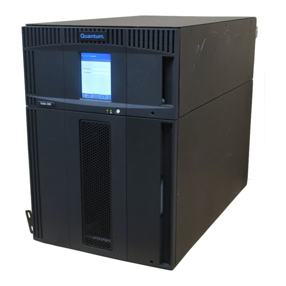
Page 17: Description
The Scalar i500 tape library is different from other tape libraries because it is an intelligent library. The Scalar i500 tape library offers advanced management features and reliability as well as scalable performance and storage capacity. -
Page 18: Figure 2 14U Library Configuration (5U Control Module Plus One 9U Expansion Module)
5U control module Figure 2 14U Library Configuration (5U Control Module Plus One 9U Expansion Module) 5U control module 9U expansion module Description... -
Page 19: Figure 3 23U Library Configuration (5U Control Module Plus Two 9U Expansion Modules)
Figure 3 23U Library Configuration (5U Control Module Plus Two 9U Expansion Modules) 5U control module 9U expansion module 9U expansion module Scalar i500 User’s Guide... -
Page 20: Intelligent Storage
30%. Its capacity-on-demand (COD) scalability lets it grow non-disruptively with users' data. And the Scalar i500 is designed to integrate easily with disk backup, making it the perfect library for next-generation backup architectures. With the Scalar i500, Information Technology managers can be assured they will have reliable, high-performance backup, certain restores, and effective long-term protection for years into the future, no matter how their storage needs evolve. -
Page 21: 5U Control Module
*Including I/E station slots 5U Control Module The 5U control module is required in any Scalar i500 library configuration. The 5U control module contains the robotic controls, library control blade (LCB), and touch screen display. The 5U control module also contains an import/export (I/E) station, fixed storage slots, tape drives, and at least one power supply. -
Page 22: Figure 4 Base Systems Plus 9U Expansion Modules
Figure 4 Base Systems Plus 9U Expansion Modules Description... -
Page 23: Front Panel Components
Front Panel Components The Scalar i500 library is made up of physical hardware components. Figure 5 shows the front panel components of the library. The paragraphs following Figure 5 describe the components in detail. Figure 5 Front Panel Components access door... -
Page 24: I/E Station
CARE SHOULD BE TAKEN TO AVOID OPENING THE ACCESS DOOR CAUTION DURING ROBOTIC OPERATIONS SINCE THE ROBOT WILL STOP IMMEDIATELY AND WILL FAIL TO COMPLETE THE CURRENT OPERATION. I/E Station I/E stations enable importing and exporting cartridges with minimal interruption of normal library operations. I/E stations are located on the front of the control module and on the front of expansion modules. -
Page 25: Back Panel Components
The paragraphs following Figure 6 describe the components in detail. Figure 6 Scalar i500 Back Panel Components library control blade (LCB) Upper and Lower Ethernet ports on expansion module rear power switches... -
Page 26: Rear Power Switches
Rear Power Switches Rear power switches are located on each power supply. Turning off the rear power switch on a power supply removes all power from the library. The rear power switches should be used in all emergency and service situations. -
Page 27: Library Control Blade
Blue represents power-control status. Figure 8 on page 16 shows the location of the LCB components, including LEDs. For more information on the behavior of the LCB LEDs, see LCB and FC I/O Blade LEDs on page 215. Scalar i500 User’s Guide... -
Page 28: Fc Input/Output Blades
Figure 8 Library Control Blade LEDs (blue, amber, green) Service Ethernet port Gigabit Ethernet (external Service serial port network) port Ethernet I/O blade control ports (inactive if I/O blades are not installed) FC Input/Output Blades Expansion modules support optional FC Input/Output (I/O) blades that provide connections for FC tape drives in the library. -
Page 29: Figure 9 Fc I/O Blade
Installing, Removing, and Replacing on page 101 for information on installing and cabling FC I/O blades and FC tape drives. Figure 9 FC I/O Blade FC ports to host(s) FC ports to drives LEDs (blue, amber, green) Scalar i500 User’s Guide... -
Page 30: Robotic System And Barcode Scanner
Each I/O blade is cooled by a fan blade that is installed next to the I/O blade in the expansion module. For information on installing the fan blade, see Adding, Removing, and Replacing the I/O Fan Blade page 201. Figure 10 shows the I/O fan blade, including the LED. -
Page 31: Tape Drive Support
194. Library Features This section describes several features of Scalar i500 libraries. Licensable Features In Scalar i500 libraries, LTO storage slots are licensed for use. The following situations may require you to enter a license key: Scalar i500 User’s Guide... -
Page 32: Capacity-On-Demand (Cod)
Capacity-On-Demand (COD) All Scalar i500 library configurations ship with the purchased number of slots pre-activated. At any time, the COD feature allows you to enable the inactive storage slots within a library by using COD license keys. COD license keys are available in 46-slot increments. For information on obtaining a COD license key, see Obtaining a Capacity-On-Demand License Key on page 53. -
Page 33: User Interface
52. Support for WORM Scalar i500 tape libraries support WORM (write once, read many) technology in LTO-3 and LTO-4 tape drives. WORM allows non-rewriteable and non-erasable data to be written and provides extra data security by prohibiting accidental data erasure. The WORM feature is supported whenever you use WORM cartridges. - Page 34 Description...
-
Page 35: Understanding The User Interface
Understanding the User Interface The user interface of Scalar i500 libraries is available in two formats: the operator panel and the web client. Operations on the Scalar i500 library can be performed locally on the control module using the operator panel or remotely on your computer using the web client. -
Page 36: Figure 11 Operator Panel User Interface
Figure 11 Figure 12 on page 24 show the operator panel and the web client interfaces. Figure 11 Operator Panel User Interface Figure 12 Web Client User Interface Understanding the User Interface... -
Page 37: System Summary And Subsystem Status
For more information about user privileges, see User Privileges on page 29 and Working With User Accounts on page 58. On the web client interface, users can toggle between the Capacity View and the Library View. Scalar i500 User’s Guide... -
Page 38: Library View
Library View Selecting the Library View button on the web client displays the Library View. The Library View provides a graphical representation of the library as well as another mode of navigation. Use the Library View to navigate through the library. The control module is labeled with “hot” areas that can be selected to access the functions for each area of the library. -
Page 39: Table 2 Web Client Menus
Firmware >LDAP IO Blades >Port Configuration >Channel Zoning >Host Mapping >Host Management >Host Port Failover >Data Path Conditioning >Blade Control Date and Time Register Library Administrative users only. Available only when the library contains I/O blades. Scalar i500 User’s Guide... -
Page 40: Table 3 Operator Panel Menus
Table 3 lists the operator panel menus. Some menu commands are available only to users with administrative privileges. I/O blade menu items are available for libraries that contain I/O blades. Table 3 Operator Panel Menus Setup Menu Operations Menu Tools Menu Setup Wizard Move Media All RAS Tickets... -
Page 41: User Privileges
Working With User Accounts on page 58 for more information on setting user privilege levels. Three types of users are defined in Scalar i500 libraries: • Administrative users have access to the entire physical library and all of its partitions. The library ships with a default administrative user account. -
Page 42: User Access
• All users are logged out automatically after a configurable period of inactivity. The default timeout period is 30 minutes, but users with administrative privileges can change this to a value from 15 minutes to 480 minutes (eight hours). See Configuring System Settings on page 72.A screen saver is invoked after 10 minutes of inactivity on the operator panel. -
Page 43: Configuring Your Library
When you power on the library for the first time, you do not need to log in to use the operator panel. You can start using the Setup Wizard immediately. After the initial setup session on the operator panel, however, you will need to log in to the operator panel as well as the web client. Scalar i500 User’s Guide... -
Page 44: Completing The Library Configuration With Menu Commands
The library ships with a default administrative user account. The user name on the account is admin and the password is password. When you see the Login screen on the operator panel or web client, type admin in the User Name text box and password in the Password text box. As soon as the initial setup is complete, you should change the password on the default administrative account. -
Page 45: Setup Wizard Tasks
Setup Wizard. This chapter includes detailed descriptions of the configuration tasks, including how and when to access them through the Setup and Operations menus. • Welcome (operator panel) — Welcomes you to the Setup Wizard. Scalar i500 User’s Guide... -
Page 46: Choosing The Interface: Local Or Remote
• Hardware Installation (operator panel) — Reminds you to install tape drives and the Ethernet cable. • Setting the Date and Time (operator panel and web client) — Allows you to set the date and time on your library. • Managing the Network (operator panel) —... -
Page 47: Remote Configuration
DNS settings are optional. If you modify the IP address, you will need to type the new IP address in the Address field of your Web browser to access the web client. Scalar i500 User’s Guide... - Page 48 Make sure that the library is connected to the network before modifying Note network settings. If the Ethernet cable is not installed properly, you cannot configure the network settings. Install one end of the Ethernet cable in the top Ethernet port located at the back of the library just below the three LEDs. Make sure the other end of the Ethernet cable is installed in the appropriate LAN port on your LAN.
-
Page 49: Enabling Ssl
Registering External Management Applications on page 38. • Enable or disable support for SNMP v1 and v2c. SNMP v3 is enabled by default and cannot be disabled. For more information, see Enabling SNMP Versions on page 39. Scalar i500 User’s Guide... -
Page 50: Registering External Management Applications
• Modify the default Read SNMP community string, which is used as a password to authenticate GET and GET-NEXT SNMP v1 and SNMP v2c messages exchanged between the library and a remote management application. For more information, see Modifying the Read SNMP Community String on page 39. -
Page 51: Enabling Snmp Versions
Getting More Information or Help on page 4. For information on integrating MIBs with an SNMP management application, contact your network management application vendor. The SNMP MIB is also available on the Scalar i500 Documentation and Note Training CD. Scalar i500 User’s Guide... -
Page 52: Working With Partitions
You cannot download the SNMP MIB from the operator panel. The path to open the appropriate screen is as follows: • From the web client select Tools > Download SNMP MIB. Working With Partitions The Setup Wizard: Partitioning screens allow administrative users to select the number of new library partitions to create. -
Page 53: Automatically Creating Partitions
Only FC tape drives and the library The first FC tape drive assigned to a partition is designated and itself does not contain any FC I/O enabled as the control path tape drive by default. blades Scalar i500 User’s Guide... -
Page 54: Manually Creating Partitions
Table 5 Control Path Assignment During Automatic Partitioning If a partition contains... Then control path assignment is as follows... Only FC tape drives and there is at The FC I/O blade is designated as the control path for the least one FC I/O blade installed in the partition, even if the partition has no tape drives connected to library the FC I/O blade. -
Page 55: Table 6 Control Path Assignment During Manual Partitioning
It can also affect what devices are presented to the host application. If a tape drive is seen multiple times by the host, check to see if a control path has been defined for the partition and remove it. See Configuring Host Mapping page 68 for information on host mapping. Scalar i500 User’s Guide... - Page 56 When creating partitions manually, you need to provide the following information: Emulation Type — the type of library that the partition is emulating • • Scalar i500 (default) • Scalar 24 • Scalar 100 • Scalar i2000 • Partition Name — limited to a maximum of 12 lower-case alphanumeric characters and underscores ( _ ) •...
-
Page 57: Modifying Partitions
See Changing Partition Access on page 46. You may need to modify settings in your host application as a result of deleting Note a partition. See your host application documentation. Scalar i500 User’s Guide... -
Page 58: Deleting Partitions Before Removing Or Replacing Modules
This operation cannot be performed concurrently by multiple administrative Note users logged in from different locations. You can access the screen, but you cannot apply changes while another administrative user is performing the same operation. Deleting Partitions Before Removing or Replacing Modules You should delete partitions before: •... -
Page 59: Changing Partition Modes
You can disable manual cartridge assignment by clearing the Manual Cartridge Assignment check box on the operator panel System Settings screen. For more information on system settings, Configuring System Settings on page 72. Scalar i500 User’s Guide... -
Page 60: Understanding Host Application Notification
Understanding Host Application Notification When manual cartridge assignment is enabled, SCSI Unit Attention 6/2801 notifies the host application when the I/E station has been accessed, allowing the host to automatically detect the presence of media in the I/E station and update its I/E station status information. When manual cartridge assignment is disabled, host notification via SCSI Unit Attention 6/2801 depends on the number of configured partitions: •... -
Page 61: Configuring I/E Station Slots
If you increase the size of your library by adding 9U expansion modules, the I/E stations in the new modules will be storage slots by default. You can select to reconfigure these slots as I/E slots. Scalar i500 User’s Guide... -
Page 62: Configuring Zero I/E Station Slots
• Based on the number of I/E slots you configure, the library automatically determines which I/E stations to configure as I/E slots and which to configure as storage. • The library configures I/E slots in the control module I/E station first and then works outward to the I/E stations in the 9U expansion modules. -
Page 63: Setting Tape Drive Parameters
The requested topology connection mode can be set to one of the following: • Auto (LN) — Auto-configure trying L-Port first • Loop (L) — Force L-Port • Point to Point — Force N-Port • Auto (NL) — Auto-configure trying N-Port first (default) Scalar i500 User’s Guide... -
Page 64: Modifying The Control Path
• The requested interface speed can be set to Auto (default), 1 Gb/s, 2 Gb/s, and 4Gb/s. When you set the speed to 4Gb/s using the web client, a caution message appears informing you that the 4Gb/ s speed selection may not be applicable to all FC tape drives installed in the library. Acknowledge the message by clicking OK. -
Page 65: Applying License Keys
From the operator panel, select Setup > Licenses. Obtaining a Capacity-On-Demand License Key All Scalar i500 library configurations ship with the purchased number of slots pre-activated. The number of available pre-activated slots begins at 36 for all library configurations and increases in 46-slot increments to a maximum of 402 slots in the 41U library configuration. -
Page 66: Table 8 Available Slots And Cod Upgrades Per Configuration
When you purchase a COD slot upgrade, Quantum issues you an Authorization Code Certificate containing a code that enables you to retrieve your COD license key from the Quantum Capacity Upgrade website. You can then activate your COD slot upgrade by loading the license key on the library through the operator... -
Page 67: Setting Customer Contact Information
Access the Quantum Scalar i500 Capacity Upgrade website at http://license.quantum.com/quantum. The Quantum Scalar i500 Capacity Upgrade website allows you to enter your authorization code and your library's Serial Number. In the Serial Number box, enter your Serial Number. Click Submit. -
Page 68: Working With E-Mail Notifications
57 for information on setting up additional e-mail notifications. The library supports a maximum of 20 e-mail notification recipients, including the default support e-mail notification. The default techsup@quantum.com e-mail notification settings can be Note modified, but not deleted. The e-mail address, techsup@quantum.com, cannot be modified. Configuring Your Library... -
Page 69: Creating E-Mail Notifications
The default techsup@quantum.com e-mail notification settings can be Note modified, but not deleted. The e-mail address, techsup@quantum.com, cannot be modified. The path to open the appropriate screen is as follows: • From the web client, select Setup > Notification > Setup. -
Page 70: Deleting E-Mail Notifications
The default techsup@quantum.com e-mail notification settings can be Note modified, but not deleted. The e-mail address, techsup@quantum.com, cannot be modified. The path to open the appropriate screen is as follows: • From the web client, select Setup > Notification > Setup. -
Page 71: Modifying Local User Accounts
Once LDAP is enabled, users can log into the library using either LDAP or local authentication. To use LDAP authentication, a user must enter a directory service user name and password and specify an LDAP domain. To use local authentication, a user must enter only a local user name and password. Scalar i500 User’s Guide... - Page 72 Administrative users can add, delete, and modify only local user account information. The library web client and operator panel do not allow you to create, modify, or delete user account information on an LDAP server. This must be done by the directory service provider. For more information on working with local user accounts, see About Local User Accounts on page 58.
-
Page 73: Setting The Date And Time
The library supports the Network Time Protocol (NTP). NTP allows you to synchronize the library date and time with other components in your IT infrastructure. Administrative users can either modify the date and time zone settings manually or configure NTP. Scalar i500 User’s Guide... -
Page 74: Working With Fc I/O Blades
If NTP is enabled, the time zone and IP addresses of at least one NTP server must be configured on the library. Contact your network administrator for NTP server IP address information. You can use the Setup Wizard - Date & Time screen to enable and configure NTP. You can also access the Date &... -
Page 75: Configuring Fc I/O Blade Ports
208. The paths to open the appropriate screens are as follows: • From the web client, Setup > I/O Blades > Port Configuration. • From the operator panel, select Setup > I/O Blades > Port Configuration. Scalar i500 User’s Guide... -
Page 76: I/O Blade Internal Virtual Port For Media Changers
Each I/O blade can access all medium changer devices, except those that are defined in association with drive-based access (aka "LUN-1"). The Scalar i500 library can have up to 18 partitions. These internal virtual ports are not configurable via channel zoning; thus, all medium changer devices are accessible via ports 1 and 2 of each FC I/O blade present within the library. -
Page 77: Managing Fc Hosts And Host Mapping
From the operator panel, select Setup > I/O Blades > Blade Control. Viewing FC Host Information The following information is provided for FC hosts: • Host Name — the host device name • I/O Blade — the location of the FC I/O blade in the library Scalar i500 User’s Guide... -
Page 78: Adding, Modifying, And Deleting An Fc Host Connection
• Status — the online/offine (connectivity) status of the host • Host Port — the host port number WWNN — the World Wide Node Name of the host device • • Type — the operating system of the host device The paths to open the appropriate screens are as follows: •... -
Page 79: Host Mapping
If the host mapping capabilities are used to control visibility and access for all the LUNs, channel zoning might not be necessary or desired. Scalar i500 User’s Guide... - Page 80 On the operator panel, the host mapping screens (Setup > I/O Blades > Host Note Mapping) are not available unless FC host mapping is enabled. See Enabling/ Disabling FC Host Mapping on page 65. Configuring Host Mapping To configure host mapping, you need to select the partition, tape drive, or media changer you want to map and assign a new LUN number for the device.
-
Page 81: Configuring Fc Host Port Failover
This operation should not be performed concurrently by multiple administrative Note users logged in from different locations. You can access the appropriate screens, but you cannot apply changes while another administrative user is performing the same operation. Scalar i500 User’s Guide... -
Page 82: Repairing And Enabling A Failed Target Port
The paths to open the appropriate screens are as follows: From the web client, select Setup > I/O Blades > Host Port Failover. • • From the operator panel, Setup > I/O Blades > Host Port Failover. Repairing and Enabling a Failed Target Port After host port failover occurs, the failed target port must be repaired and enabled before it can be configured as an active or standby port for the host port failover feature. -
Page 83: Working With Data Path Conditioning
• SNMP — enables or disables SNMP traffic (port 161) across the Ethernet port. This setting is enabled by default. • SMI-S — enables or disables SMI-S traffic (port 5988). This setting is enabled by default. Scalar i500 User’s Guide... -
Page 84: Configuring The Internal Network
You cannot configure the security settings from the web client. The path to open the appropriate screen is as follows: • From the operator panel, select Tools > Security Settings. Configuring the Internal Network Use the Internal Network Configuration screen to configure your library’s internal network setting. The default internal network address is 10.10.10.X. -
Page 85: Configuring Operator Panel Display Settings
Setup > Register Library on the web client to access the online product registration form. You cannot register the library from the operator panel. The path to open the appropriate screen is as follows: • From the web client, select Setup > Register Library. Scalar i500 User’s Guide... - Page 86 Configuring Your Library...
-
Page 87: Running Your Library
Use LDAP Authentication — Users can select this option to select or enter a domain and log in using a directory service user name and password. For more information on LDAP, see Configuring LDAP on page 59 in. Scalar i500 User’s Guide... -
Page 88: Logging Out
Logging Out Logging out secures the library from being accessed by unauthorized users. Log out whenever you have finished accessing the library through either the web client or the operator panel. From the web client or the operator panel, you can click the LOGOUT button at the top right of the screen to log out. -
Page 89: Modules
Power Supplies Power supplies are addressed as [module,PS#], where PS# is 1 for the left power supply and 2 for the right power supply. The PS# is also etched on the module chassis, above each power supply. Scalar i500 User’s Guide... -
Page 90: Performing Media Operations
Performing Media Operations Administrative users and users can use commands on the web client and operator panel Operations menu to perform the following media operations: • Import data cartridges into the library • Export data cartridges from the library • Move data cartridges between tape drives, I/E stations, and storage slots within a partition •... - Page 91 The paths to open the appropriate screens are as follows: • From the web client, select Operations > Media > Import. • From the operator panel, select Operations > Import Media. Scalar i500 User’s Guide...
-
Page 92: Bulkloading
For step-by-step procedures, see the library’s online Help. To access the online Help system, click the Help icon at the top right of the web client or operator panel user interface. Bulkloading Bulkloading is another way to load media into the library. If zero I/E station slots have been configured, you will always need to bulkload cartridges into the library. -
Page 93: Moving Media
If the partition is online, it will be taken offline before the move is performed and brought back online after the move is complete. You will be asked to confirm that you want to take the partition offline. Scalar i500 User’s Guide... -
Page 94: Exporting Media
• You can select only the partitions to which you have been given access. • You can only move media within one partition at a time. You need to provide the following information in the user interface to move media: •... -
Page 95: Loading Tape Drives
The paths to open the appropriate screens are as follows: • From the web client, select Operations > Drives > Load. • From the operator panel, select Operations > Load Drive. Scalar i500 User’s Guide... -
Page 96: Unloading Tape Drives
For step-by-step procedures, see the library’s online Help. To access the online Help system, click the Help icon at the top right of the web client or operator panel user interface. Unloading Tape Drives The Unload Drive operation allows you to unload a cartridge from a tape drive to a storage slot. The storage slot and tape drive must be assigned to the same partition. -
Page 97: About Cleaning Tape Drives
(no cleaning slots have been configured), the library generates a RAS ticket informing the user that the tape drive needs cleaning. Administrative users can clean tape drives manually, using commands on the operator panel or web client. For more information, see About Tape Drive Operations page 88. Scalar i500 User’s Guide... -
Page 98: Enabling Autoclean
Enabling AutoClean To enable AutoClean, an administrative user must configure at least one cleaning slot in the library. For information on configuring cleaning slots, see Configuring Cleaning Slots on page 48. For a description of AutoClean, see About Cleaning Tape Drives on page 85. -
Page 99: Exporting Cleaning Media
Use an asterisk (*) to search with wildcards. You can also sort the list by clicking on columns with bold headings. For example, selecting the Location column heading sorts the list by location coordinates Scalar i500 User’s Guide... -
Page 100: About Tape Drive Operations
The paths to open the appropriate screens are as follows: From the web client, select Operations > Cleaning Media > Export. • • From the operator panel, select Operations > Export Cleaning Media. For step-by-step procedures, see the library’s online Help. To access the online Help system, click the Help icon at the top right of the web client or operator panel user interface. -
Page 101: Locking And Unlocking The I/E Stations
The Setup - Blade Control screen allows you to perform the following operations on the selected I/O blades: • Click On to turn on the I/O blade. • Click Off to turn off the I/O blade. Scalar i500 User’s Guide... -
Page 102: Shutting Down Or Restarting The Library
• Click Cycle to power cycle the I/O blade. It takes approximately 3 minutes to power cycle a blade. This operation should not be performed concurrently by multiple administrative Note users logged in from different locations. You can access the appropriate screens, but you cannot apply changes while another administrative user is performing the same operation. -
Page 103: Getting Information
(SN), logical SN, World Wide Node Name (WWNN), World Wide Port Name (WWPN), topology request, speed request, topology actual, speed actual, SCSI or loop ID, firmware level, and control path setting of each tape drive Scalar i500 User’s Guide... -
Page 104: Viewing Network Settings
• Slots — including the type, assigned partition (storage and import/export [I/E] station slots only), location coordinates, barcode (storage and I/E station slots only), cartridge type, cleaning status (cleaning slot only), and element address of each slot • Partitions — including the name, mode status, emulation type, barcode policy, total tape drives, active tape drives, total cartridges, mounted cartridges, total slots, full slots, total I/E stations, full I/ E stations, and AutoClean setting of each partition Modules —... -
Page 105: Viewing I/O Blade Information
The paths to open the appropriate screens are as follows: • From the web clientweb user interface, select Tools > IO Blade Port Info From the operator panel, select Tools > IO Blade Info > Port Info • Scalar i500 User’s Guide... -
Page 106: Viewing Information About The Scalar I500
From the About screen, you can also navigate to other screens for information about the tape drives and partitions. The paths to open the appropriate screens are as follows: • From the web client, select Reports > About Scalar i500. From the operator panel, select Tools > About Library. • Getting Information... -
Page 107: Updating Library And Tape Drive Firmware
There are two types of firmware that can be updated on the library: library firmware (including drive sled firmware) and tape drive firmware. There may be times when you will need to update your library and tape drive firmware as directed by technical support. You can also regularly monitor the Quantum Support website at www.quantum.com/support... -
Page 108: Updating Tape Drive Firmware
You can find instructions on updating library firmware in the library firmware upgrade package you download from the Quantum Support website. You can also find step-by-step instructions in your library's online Help. To access the online Help system, click the Help icon at the top right of the web client or operator panel user interface. -
Page 109: Creating A Fup Tape
You can find detailed instructions on updating library firmware in the firmware upgrade package you download from the Quantum Support website. You can also find step-by-step instructions in your library's online Help. To access the online Help system, click the Help icon at the top right of the web client or operator panel user interface. -
Page 110: Erasing A Fup Tape
You can find detailed instructions on creating FUP tapes and using them to update tape drive firmware in the tape drive firmware upgrade package you download from the Quantum Support website.You can also find step-by-step instructions in your library's online Help. To access the online Help system, click the Help icon at the top right of the web client or operator panel user interface.web client... -
Page 111: Autoleveling Tape Drive Firmware
You can find detailed instructions on creating FUP tapes and using them to update tape drive firmware in the tape drive firmware upgrade package you download from the Quantum Support website.You can also find step-by-step instructions in your library's online Help. To access the online Help system, click the Help icon at the top right of the web client or operator panel user interface.web client... -
Page 112: Uploading Tape Drive Firmware Used In Autoleveling
4. You must have access to a tape drive firmware image file to enable autoleveling. Tape drive firmware is available at the Quantum Support website. Navigate to the appropriate firmware version and download the file to your computer hard drive. -
Page 113: Installing, Removing, And Replacing
REQUIRED TO SAFELY LIFT THE MODULES INTO POSITION. Taking the Library Online/Offline Taking a library online makes it accessible to host applications via the Storage Area Network (SAN). Taking a library offline makes it inaccessible to host applications via the SAN. Scalar i500 User’s Guide... -
Page 114: Taking A Library Online
Taking a Library Online Using the library’s operator panel or the remote web clientinterface, select Operations > Change Partition ModeLogical Library Mode. For each partition that you want to take online, click Online. Click Apply. Taking a Library Offline Using the library’s operator panel or the remote web clientinterface, select Operations > Change Partition ModeLogical Library Mode. -
Page 115: Figure 16 Multi-Module Scsi Cabling
The instructions include procedures for removing and replacing tape drives. Connect the SCSI cables to the tape drives. a. Terminate the SCSI tape drive with an appropriate SCSI terminator. b. Connect the SCSI tape drive to the host. Scalar i500 User’s Guide... - Page 116 Connect the module-to-module cables. The module terminator is not the same as a SCSI terminator. Using a CAUTION SCSI terminator instead of a module terminator will damage the library. a. Using the module terminators, terminate the top and bottom modules in the library stack. Install one module terminator in the top terminator connector on the topmost module and one in the bottom terminator connector on the bottommost module.
-
Page 117: Connecting Library Fc Cables Directly To Host
FC tape drives that are connected directly to a host. Figure 17 Stand-Alone 5U Control Module Fibre Channel Cabling Ethernet cable to customer power cord network fibre cable to host GB Ethernet port library control blade (LCB) power supply module terminators rear power switch Scalar i500 User’s Guide... -
Page 118: Figure 18 Multi-Module Fibre Channel Cabling
Figure 18 Multi-Module Fibre Channel Cabling Ethernet cable to customer power cords network fibre cables to host GB Ethernet port module terminators power supplies library control blade(LCB) rear power switches module-to-module cable ALL LIBRARIES TALLER THAN 14U MUST BE INSTALLED IN A RACK WARNING HAVING A MAIN PROTECTIVE EARTHING (GROUNDING) TERMINAL, AND POWER MUST BE SUPPLIED VIA AN INDUSTRIAL PLUG AND... - Page 119 Turn on the front power switch. c. Power up the host system. Verify communication with all devices on the bus. Configure the library using the commands on the operator panel. See configuration information in Configuring Your Library on page 31. Scalar i500 User’s Guide...
-
Page 120: Connecting Library Fc Cables To Fc I/O Blades
Connecting Library FC Cables to FC I/O Blades These instructions explain how to install the FC cables that connect the FC drives to the FC I/O blades. The FC I/O blades support connections to LTO-2, LTO-3, and LTO-4 drives. For information on installing FC I/O blades, see Adding, Removing, and Replacing FC I/O Blades on page 196. -
Page 121: Figure 19 Fc I/O Blade
Initiator ports 3 – 6 to drives LEDs (blue, amber, green) Use the following procedure, along with Figure 20, if you are installing a library that includes FC tape drives that are connected to FC I/O blades. Scalar i500 User’s Guide... -
Page 122: Figure 20 Fc With I/O Blade Cabling
Figure 20 FC With I/O Blade Cabling Library control blade (LCB) FC cable to tape drive GB Ethernet port Module terminator Power supplies FC cable to host Power cords Module-to-module cable Ethernet cable from LCB to 10 Ethernet cable to customer expansion module network Installing, Removing, and Replacing... - Page 123 Repeat the above steps for each FC drive you want to connect to the I/O blade. Do not connect any of these FC cables to ports 1 or 2 on the FC I/O blade. Connect the host(s) to ports 1 and/or 2 on the FC I/O blade. Scalar i500 User’s Guide...
-
Page 124: Recommended Library Cabling For Fc I/O Blades
Install the module terminators. The module terminator is not the same as a SCSI terminator. Using a CAUTION SCSI terminator instead of a module terminator will damage the library. a. Using the module terminators, terminate the top and bottom modules in the library stack. Install one module terminator in the top terminator connector on the topmost module and one in the bottom terminator connector on the bottommost module. - Page 125 Table 9 provides an example of a 41U library with I/O blade-attached tape drives. The information next to the image shows each tape drive and the I/O blade and port to which each tape drive is connected. Scalar i500 User’s Guide...
-
Page 126: Table 9 Recommended Fibre Channel Cabling With I/O Blades In Maximum Capacity Library
Table 9 Recommended Fibre Channel Cabling With I/O Blades in Maximum Capacity Library Recommended Cabling Tape Drive I/O Blade I/O Blade Port [1,1] N/A (direct attached) [1,2] N/A (direct attached) [1,3] [1,2] Port 3 [1,4] [1,2] Port 4 [0,1] [1,2] Port 5 [0,2] [1,2]... -
Page 127: Connecting Library Sas Cables
(24 INCHES) IN THE FRONT AND BACK OF THE LIBRARY. Figure 21 Stand-Alone 5U Control Module SAS Cabling Ethernet cable to customer power cord network SAS cable to host GB Ethernet port library control blade power supply module terminators rear power switch Scalar i500 User’s Guide... -
Page 128: Figure 22 Multi-Module Sas Cabling
Figure 22 Multi-Module SAS Cabling module-to-module cable power cords library control blade SAS cables to host GB Ethernet port module terminators power supply Ethernet cable to customer network rear power switch If your library is 14U or larger, install it in a rack. See Installing the Rackmount Kit on page 181 for instructions. - Page 129 Turn on the front power switch. c. Power up the host system. Verify communication with all devices on the bus. 10 Configure the library using the commands on the operator panel. See configuration information in Configuring Your Library on page 31. Scalar i500 User’s Guide...
-
Page 130: Cable Management Guidelines
Customers who purchase a Fibre Channel I/O blade will receive a cable management kit with all the equipment necessary to perform these procedures. You can also order the cable management kit from http:/ /shop.quantum.com. The color of the straps matches the color of the cords they are designed to secure. Installing, Removing, and Replacing... -
Page 131: Table 10 Cable Management Kit Contents
Ethernet cables to the control module Adhesive-backed wire saddle cable clamp — for older library models without drilled holes for push-in wire saddle clamps. The adhesive-backed wire saddle clamp secures Ethernet cables to the control module. Scalar i500 User’s Guide... -
Page 132: Managing Power Cords
Managing Power Cords Power cord management is important especially for the larger, expanded library configurations. A 41U library with redundant power, the maximum configuration, may contain as many as 10 power supply units with 10 power cords to manage. To organize power cords on the rear of the library, mount a black hook-and-loop fastener to each module and then secure the power cords with the fastener. -
Page 133: Managing Ethernet Cables
Power Cord Management Managing Ethernet Cables A Scalar i500 library with I/O blades uses external Ethernet cables on the rear of the library to provide connectivity between the LCB in the control module and an expansion module. The upper and lower I/O blade bays within an expansion module each have a corresponding Ethernet port on the back of the module. - Page 134 The LCB provides ports for up to four Ethernet cables on its internal Ethernet hub. This allows the library to support up to four I/O blades. To organize Ethernet cables on the rear of the library, mount two wire saddles on the control module to route the Ethernet cable(s) to the right side of the library.
-
Page 135: Figure 24 Ethernet Cable Management
Figure 24 Ethernet Cable Management The illustration below shows how a 41U library would appear with power, Ethernet, and fibre cables installed and managed according to these guidelines. Scalar i500 User’s Guide... -
Page 136: Figure 25 Cable Management, All Cables
Figure 25 Cable Management, All Cables, Installing, Removing, and Replacing... -
Page 137: Installing A Stand-Alone 5U Control Module
14 Add the tape cartridges to the library using the I/E station. 15 If your host application inventories the location of each tape cartridge in the library, open the host application and re-inventory to sync the logical inventory with the physical inventory of the library. Scalar i500 User’s Guide... -
Page 138: Installing A New Multi-Module Library Configuration
Installing a New Multi-Module Library Configuration Use this procedure for installing a new multi-module library. A multi-module library contains a control module and up to four 9U expansion modules. There are no restrictions on where the control module can be installed in the library configuration. However, the recommended placement of the control module for library configurations up to 32U is on top of all installed 9U expansion modules. - Page 139 The metal parking tab is located at the bottom of column 1. d. Gently release the robot assembly to rest on the parking tab. parking tab in “park” position Scalar i500 User’s Guide...
-
Page 140: Installing The 9U Expansion Module
Remove and replace the cover plates, if appropriate. Before removing the control module’s bottom cover plate, the robot CAUTION assembly must be parked as described in Step 4 on page 127. a. If you plan to stack the control module at the top of the library, and if a 9U expansion module will be located below it, remove the control module’s bottom cover plate and the 9U expansion module’s top plate. - Page 141 Tighten all thumbscrews located at the base of the front and back of the modules. Fasten the module to the rack with rack ears. See Installing the Rackmount Kit on page 181 for information on installing a rackmount kit. Scalar i500 User’s Guide...
- Page 142 If stacking the 9U expansion module on top of another module, engage the Y-rails of the new module in your library configuration. Ensure that the Y-rails are properly aligned and the thumbscrews are tightened. front Y-rail Y-rail (this end up) rear Y-rail squeeze here to release Installing, Removing, and Replacing...
- Page 143 Y-rails on both the front and back of the library. If a gap exists, the library cannot mechanically initialize. Doing this aligns the Y-rails with the Y-rails of the module beneath it. Y-rail in unlocked, functional position Repeat these steps for each expansion module you are installing. Scalar i500 User’s Guide...
-
Page 144: Installing The 5U Control Module
Installing the 5U Control Module Open the control module’s I/E station door and access door. Lift the control module and place it in the desired location. If stacking the control module on top of another module, secure the two modules together by tightening the two thumbscrews at the base of the front of the module and the two thumbscrews located at the base of the back of the module. - Page 145 For cabling instructions, see Cabling the Library on page 102. Power on the library. For libraries larger than a 14U, boot time may take 15-20 minutes. Scalar i500 User’s Guide...
-
Page 146: Adding 9U Expansion Modules To An Existing Library
The latest firmware must be installed on the library if you are upgrading from a 5U or 14U configuration to a larger configuration. The latest firmware can be found at www.quantum.com/ support.See Updating Library and Tape Drive Firmware on page 95 for more information. - Page 147 SUPPLIES, A 5U CONTROL MODULE WEIGHS APPROXIMATELY 58 LBS. A 9U EXPANSION MODULE, WITHOUT TAPE DRIVES, TAPE CARTRIDGES, OR POWER SUPPLIES, EXCEEDS 65 LBS. TO AVOID SERIOUS INJURY, AT LEAST TWO PEOPLE ARE REQUIRED TO SAFELY LIFT THE MODULES INTO POSITION. Scalar i500 User’s Guide...
-
Page 148: Preparing To Install An Additional 9U Expansion Module
Preparing to Install an Additional 9U Expansion Module Required tools: • Phillips #2 screwdriver, for removing and replacing the top cover plate • T10 TORX screwdriver, for removing and replacing the bottom cover plate You need to unstack the library to install the new 9U Expansion Module expansion module at the bottom of the new library configuration. -
Page 149: Unstacking The Existing Modules
Before unstacking the modules, the robot assembly must be parked CAUTION as described in Step 5 on page 136. If your current configuration already uses a 9U expansion module, disengage the Y-rails so the modules can be safely unstacked. Scalar i500 User’s Guide... - Page 150 a. From the front of the library, find the Y-rail release mechanism, which is located on the left side of the module. Squeeze the handle of the Y-rail release mechanism, lift it, and release it so that it locks into place. b.
- Page 151 Loosen the thumbscrews located at the base of the front and rear of the module. Thumbscrews (behind doors) Scalar i500 User’s Guide...
-
Page 152: Installing The New 9U Expansion Module
Open the module’s access door and raise the guide pin by pulling it up and turning it slightly as if it were a screw. Otherwise, the guide pin may scratch the front doors of the module beneath it. guide pin thumbscrew From the front of the library, slide the entire module toward you and lift it off of the module below it. -
Page 153: Table 12 Cover Plate Location After Adding A 9U Expansion Module
5U Control NEW 9U NEW 9U NEW 9U 9U Expansion Module Expansion Expansion Expansion Module Module* Module* Module* cover plate cover plate cover plate cover plate cover plate * Recommended location for adding an expansion module. Scalar i500 User’s Guide... - Page 154 Open the 9U expansion module’s access door and raise the guide pin by pulling it up and turning it slightly as if it were a screw. Otherwise, the guide pin may scratch the front doors of the module on which you are stacking it.
- Page 155 From the front of the library, open the I/E station and access doors of the 9U expansion module. b. Squeeze the handle of the Y-rail release mechanism, lift it out of its locked position, and slide it downward as far as it will go. Scalar i500 User’s Guide...
-
Page 156: Preparing To Use The Library
c. From the back of the library, find the rear Y-rail release mechanism, which is located in the interior of the right side of the module. Squeeze the handle of the Y-rail release mechanism, lift it out of its locked position, and slide it downward as far as it will go. Doing this aligns the Y-rails with the Y-rails of the module beneath it. - Page 157 When replaced correctly, the parking tab will not accidentally swivel into the path of the robot. c. Gently release the robot assembly. It will lower to the bottom module of the library. parking tab in “unpark” position Scalar i500 User’s Guide...
-
Page 158: Removing 9U Expansion Modules From An Existing Library
Connect all power cords, network data cables, and module-to-module cables. Make sure the module terminators are installed at the top and bottom of the stack of modules. For cabling instructions, see Cabling the Library on page 102. Power on the library. Reconfigure the library, including applying the new COD license key, using the operator panel or web client. -
Page 159: Preparing To Permanently Remove The 9U Expansion Module
After raising the robot assembly to the approximate middle of the control module, hold it in place with one hand and, using your other hand, swivel the parking tab toward you. The metal parking tab is located at the bottom of column 1. Scalar i500 User’s Guide... -
Page 160: Removing The 9U Expansion Module
d. Gently release the robot assembly to rest on the parking tab. parking tab in “park” position Remove all power supplies from each module that you intend to remove. For details, see Adding, Removing, and Replacing Power Supplies on page 179. Remove all tape drives from each module that you intend to remove. - Page 161 Disengage the Y-rails so the modules can be unstacked safely. front Y-rail Y-rail (this end up) rear Y-rail squeeze here to release Scalar i500 User’s Guide...
- Page 162 a. From the front of the library, find the Y-rail release mechanism, which is located on the left side of the control module. Squeeze the handle of the Y-rail release mechanism, lift it, and release it so that it locks into place. b.
- Page 163 Otherwise, the guide pin may scratch the front doors of the module beneath it. From the front of the library, slide the entire module toward you and lift it off of the module below it. Repeat these procedures for each module that you intend to remove. Scalar i500 User’s Guide...
-
Page 164: Table 13 Cover Plate Location After Removing A 9U Expansion Module
Remove and replace the cover plates, if appropriate. Before removing the control module’s bottom cover plate, the robot CAUTION assembly must be parked as described in Step 5 on page 147. a. If you plan to stack the control module at the top of the library, and if a 9U expansion module will be located below it, remove the control module’s bottom cover plate and the 9U expansion module’s top plate. -
Page 165: Preparing To Use The New Library Configuration
Preparing to Use the New Library Configuration Ensure that the Y-rails are properly aligned and the thumbscrews are tightened. front Y-rail Y-rail (this end up) rear Y-rail squeeze here to release Scalar i500 User’s Guide... - Page 166 a. From the front of the library, open the I/E station and access doors of the 9U expansion module. Squeeze the handle of the Y-rail release mechanism, lift it out of its locked position, and slide it downward as far as it will go. b.
- Page 167 When replaced correctly, the parking tab will not accidentally swivel into the path of the robot. c. Gently release the robot assembly. It will lower to the bottom module of the library. parking tab in “unpark” position Close the library’s I/E station and access doors. Scalar i500 User’s Guide...
-
Page 168: Replacing The 5U Library Control Module
Connect all power cords, network data cables, and module-to-module cables. Make sure the module terminators are installed at the top and bottom of the stack of modules. For cabling instructions, see Cabling the Library on page 102. Power on the library. 10 Add the tape cartridges to the library’s modules using the I/E station commands from the operator panel or web client. -
Page 169: Preparing To Remove The 5U Control Module
After raising the robot assembly to the approximate middle of the control module, hold it in place with one hand and, using your other hand, swivel the parking tab toward you. The metal parking tab is located at the bottom of column 1. Scalar i500 User’s Guide... -
Page 170: Removing The 5U Control Module
d. Gently release the robot assembly to rest on the parking tab. parking tab in “park” position If there are expansion modules stacked above the control module, remove them now. Removing the 5U Control Module Starting with the topmost module of your library, open the I/E station and access doors of the module. Before unstacking the modules, the robot assembly must be parked CAUTION as described in... - Page 171 The rear Y-rail is impossible to lift up with the tape drives installed. Note front Y-rail Y-rail (this end up) rear Y-rail squeeze here to release Remove the rack ears that fasten the module to the rack. Scalar i500 User’s Guide...
- Page 172 Loosen the thumbscrews located at the base of the front and rear of the module. 5U Library Control Module (front) thumbscrews 5U Library Control Module (rear) Installing, Removing, and Replacing...
-
Page 173: Replacing The 5U Control Module
If you plan to stack the control module in the middle of the library, remove both the top and bottom cover plates. d. If you plan to stack the control module at the bottom of the library, and if a 9U expansion module is located above it, remove the control module’s top cover plate. Scalar i500 User’s Guide... - Page 174 Remove the LCB from the control module and set it aside. The LCB stores information about the library’s contents and configuration, so you will probably want to install this LCB (or possibly just the LCB compact flash card) in the new control module. For details about removing the LCB, see Removing and Replacing the Library Control Blade and LCB Compact Flash Card...
- Page 175 With your free hand, swivel the parking tab away from you until it is removed completely from the interior of the module. When replaced correctly, the parking tab will not accidentally swivel into the path of the robot. Scalar i500 User’s Guide...
-
Page 176: Preparing To Use The 5U Control Module
c. Gently release the robot assembly. It will lower to the bottom module of the library. parking tab in “unpark” position Preparing to Use the 5U Control Module Close the library’s I/E station and access doors. Add the tape drives to the modules. For details, see Adding, Removing, and Replacing Tape Drives page 193. -
Page 177: Replacing A 9U Expansion Module
HAVING A PROTECTIVE EARTH (GROUND) CONDUCTOR WITH A CROSS SECTIONAL AREA OF AT LEAST 1.5 MM (14 AWG). TO ENSURE PROPER AIRFLOW AND ACCESS SPACE, ALLOW 60 CM (24 INCHES) IN THE FRONT AND BACK OF THE LIBRARY. Scalar i500 User’s Guide... -
Page 178: Preparing To Remove The 9U Expansion Module
WITHOUT TAPE DRIVES, TAPE CARTRIDGES, OR POWER WARNING SUPPLIES, A 5U CONTROL MODULE WEIGHS APPROXIMATELY 58 LBS. A 9U EXPANSION MODULE, WITHOUT TAPE DRIVES, TAPE CARTRIDGES, OR POWER SUPPLIES, EXCEEDS 65 LBS. TO AVOID SERIOUS INJURY, AT LEAST TWO PEOPLE ARE REQUIRED TO SAFELY LIFT THE MODULES INTO POSITION. - Page 179 The metal parking tab is located at the bottom of column 1. d. Gently release the robot assembly to rest on the parking tab. parking tab in “park” position Scalar i500 User’s Guide...
-
Page 180: Removing The 9U Expansion Module
Removing the 9U Expansion Module Starting with the topmost module of your library, open the I/E station and access doors of each module. Before unstacking the modules, the robot assembly must be parked CAUTION as described in Step 8 on page 167. Disengage the Y-rails so the modules can be unstacked safely. - Page 181 Remove the rack ears that fasten the module to the rack. See Installing the Rackmount Kit on page 181 for detailed instructions on using the rack ears. Loosen the thumbscrews located at the base of the front of the module. Scalar i500 User’s Guide...
- Page 182 Thumbscrews (behind doors) Loosen the two thumbscrews located at the base of the back of the module. Open the module’s access door and raise the guide pin by pulling it up and turning it slightly as if it were a screw. Otherwise, the guide pin may scratch the front doors of the module beneath it. From the front of the library, slide the entire module toward you and lift it off of the module below it.
-
Page 183: Replacing The 9U Expansion Module
Open the 9U expansion module’s access door and raise the guide pin by pulling it up and turning it slightly as if it were a screw. Otherwise, the guide pin may scratch the front doors of the module on which you are stacking it. Scalar i500 User’s Guide... - Page 184 guide pin thumbscrew Lift the new 9U expansion module and, from the front of the library, place it in the desired location. Fasten the module to the rack with rack ears. Secure the two modules together by tightening the two thumbscrews at the base of the front of the module and the two thumbscrews located at the base of the back of the module.
- Page 185 Engage the Y-rails of each module in your library configuration. Ensure that the Y-rails are properly aligned and the thumbscrews are tightened. front Y-rail Y-rail (this end up) rear Y-rail squeeze here to release Scalar i500 User’s Guide...
- Page 186 a. From the front of the library, open the I/E station and access doors of the 9U expansion module. Squeeze the handle of the Y-rail release mechanism, lift it out of its locked position, and slide it downward as far as it will go. Y-rail in unlocked, functional position b.
-
Page 187: Preparing To Use The 9U Expansion Module
If your library contains FC I/O blades, install both the I/O blades and the accompanying fan blades in the expansion module. For details, see Adding, Removing, and Replacing FC I/O Blades on page 196 Adding, Removing, and Replacing the I/O Fan Blade on page 201. Scalar i500 User’s Guide... -
Page 188: Removing And Replacing The Library Control Blade And Lcb Compact Flash Card
Add the LCB to the control module. For details, see Removing and Replacing the Library Control Blade and LCB Compact Flash Card on page 176. Connect all power cords, network data cables, and module-to-module cables. Make sure the module terminators are installed at the top and bottom of the stack of modules. For cabling instructions, see Cabling the Library on page 102. - Page 189 11 Check the status of the LCB LEDs. All of its LEDs (blue, amber, and green) should be solidly lit for a short period of time. 12 Upgrade your library firmware. a. Log on to the local operator panel as Admin. b. Setup the library network on the Network Configuration screen. Scalar i500 User’s Guide...
-
Page 190: Replacing The Lcb
Log on to the web client as Admin. e. Upgrade to the appropriate level of library firmware. Firmware downloads are available at www.quantum.com/support. Replacing the LCB These instructions explain how to remove the existing LCB and existing LCB compact flash card and replace a new LCB and reuse the existing LCB compact flash card. -
Page 191: Adding, Removing, And Replacing Power Supplies
The power supply must be level to slide in smoothly. Tighten the power supply’s thumbscrews to secure the power supply to the library module. Plug in the power supply cord. Scalar i500 User’s Guide... -
Page 192: Permanently Removing A Redundant Power Supply
Turn on the power supply’s power, using the switch on the rear of the power supply. Check the status of the power supply’s LEDs. The top green LED and the blue LED should be solidly lit. Power on the library. Check the status of the power supply’s LEDs. -
Page 193: Installing The Rackmount Kit
The rackmount kit contains all parts required for installing your library into a rack. Table 14 Rackmount Kit Contents Component Description Quantity Small ferrule — for use in racks with round holes Large ferrule — for use in racks with square holes Scalar i500 User’s Guide... - Page 194 Table 14 Rackmount Kit Contents (Continued) Component Description Quantity Thumbnut M5 thumbscrew Rack ear, left Rack ear, right Installing, Removing, and Replacing...
-
Page 195: Installing The Rackmount Shelves
Extending the shelves can be difficult, but they are designed to be resized Note by hand. Do not use tools to resize the shelves, and never take them apart. Scalar i500 User’s Guide... - Page 196 Place a ferrule on the end of each stud, and screw it on completely. The larger side of the ferrule should face the rack shelf, and the tapered end should face out. Be sure to use the proper size ferrule as described in Preparing Rackmount Kit for Installation on page 181.
-
Page 197: Preparing Your Library For Rack Installation
Power off your library and disconnect all power cords, network data cables, and module-to-module cables. Remove all tape drives from the library modules. The modules are much easier to lift into the rack without the additional weight of the tape drives. Scalar i500 User’s Guide... -
Page 198: Installing Modules In The Rack
WITHOUT TAPE DRIVES, TAPE CARTRIDGES, OR POWER WARNING SUPPLIES, A 5U CONTROL MODULE WEIGHS APPROXIMATELY 58 LBS. A 9U EXPANSION MODULE, WITHOUT TAPE DRIVES, TAPE CARTRIDGES, OR POWER SUPPLIES, EXCEEDS 65 LBS. TO AVOID SERIOUS INJURY, AT LEAST TWO PEOPLE ARE REQUIRED TO SAFELY LIFT THE MODULES INTO POSITION. - Page 199 (The flexible door hinge allows the door to be pulled away from the module, providing access to the slot.) You may need to pull the door toward you in order to access the slot. Note Scalar i500 User’s Guide...
-
Page 200: Installing Additional Modules Into The Rack
b. Using two M5 thumbscrews, fasten the rack ear to the rack. The thumbscrews should fasten completely and evenly. Close the module’s doors. Install the remaining modules of your library (if any). Reinstall the tape drives in the library. Cable your library as necessary, following the instructions provided in Cabling the Library on page 102. - Page 201 Power off the module and disconnect all power cords, network data cables, and module-to- module cables. b. Consider removing all tape drives from the module. Modules are much easier to lift into the rack without the additional weight of the tape drives. Scalar i500 User’s Guide...
- Page 202 c. Open the module’s access door and raise the guide pin by pulling it up and turning it slightly as if it were a screw. Otherwise, the guide pin may scratch the front doors of the module on which you are stacking it. guide pin thumbscrew Lift the module, align it so that it is parallel with the module below it, and slide it into place.
- Page 203 Secure the module to the module beneath it by tightening the thumbscrews located at the base of the front and back of the module. Press down the thumbscrew, and then tighten it. 5U Library Control Module (front) thumbscrews 5U Library Control Module (rear) Scalar i500 User’s Guide...
- Page 204 Install the right rack ear. At the front of the library: a. Open the I/E station door. At the lower right corner of the module is a vertical slot. Insert the hinge of the right rack ear into the slot and then position the holes of the rack ear flush with the rack rail.
-
Page 205: Adding, Removing, And Replacing Tape Drives
Newly added tape drives need to be installed and verified one at a time. Note Alternatively, all of the tape drives can be added to the drive bays at one time with no wait time between adding tape drives. Scalar i500 User’s Guide... -
Page 206: Adding A Tape Drive
Adding a Tape Drive These instructions explain how to add a tape drive to your library. You can add a tape drive while the library is powered on. Required tools: None Save the library configuration. Detach the tape drive slot’s cover plate. Loosen the cover plate’s thumbscrews and remove the plate. Store the cover plate in a separate cabinet. -
Page 207: Removing And Replacing A Tape Drive
Tighten the tape drive’s thumbscrews to secure the tape drive to the module. The thumbscrews must be aligned with the module’s screw holes. If they are not aligned, the tape drive was not inserted correctly. 10 Power on the library (if it’s not powered on already). Scalar i500 User’s Guide... -
Page 208: Adding, Removing, And Replacing Fc I/O Blades
11 Check the tape drive’s LEDs to ensure that it functions correctly. When the tape drive is downloading firmware, the green LED is solidly lit for three seconds and then blinks twice. Firmware begins to download as soon as the library detects a new tape drive. Firmware downloads may take more than 15 minutes. -
Page 209: Adding An Fc I/O Blade
Remove the cover plate from the appropriate I/O blade bay. Press up and out to open the latch hooks on each side of the I/O blade. Scalar i500 User’s Guide... - Page 210 I/O blade LEDs latch hooks, open Carefully align the FC I/O blade with the guide slots in the bay. The status LEDs must be at the bottom. Forcing the blade into the bay can cause the pins to bend. CAUTION Evenly apply pressure to both sides of the blade and slide it into the expansion module until the latch hooks begin to move towards the middle of the blade.
- Page 211 FC I/O blade temperature errors will occur. Cable the library as described in Connecting Library FC Cables to FC I/O Blades on page 108. Save the library configuration. See About Saving and Restoring the Configuration on page 208. Scalar i500 User’s Guide...
-
Page 212: Removing An Fc I/O Blade
Removing an FC I/O Blade These instructions explain how to remove an FC I/O blade from your library. You can remove an FC I/O blade while the library is powered on. The library will generate a RAS ticket when you remove the I/O blade. If you do Note not want the library to generate a RAS ticket, you can power down the I/O blade before removing it. -
Page 213: Adding, Removing, And Replacing The I/O Fan Blade
Press up and out to open the latch hooks on each side of the I/O fan blade. The LED must be at the bottom of the blade. Scalar i500 User’s Guide... -
Page 214: Removing An I/O Fan Blade
I/O Fan blade latch hooks, open Forcing the blade into the bay can cause the pins to bend. CAUTION Evenly apply pressure to both sides of the blade and slide it into the expansion module until the latch hooks begin to move towards the middle of the blade. Push the latch hooks towards the middle of the blade and into the locked position. -
Page 215: Replacing An Fc I/O Fan Blade
As you push in on the blade, you will feel the blade pins connect with the expansion module’s backplane. Push the latch hooks into the locked position. Save the library configuration. See About Saving and Restoring the Configuration on page 208. Scalar i500 User’s Guide... - Page 216 Installing, Removing, and Replacing...
-
Page 217: Troubleshooting
All RAS Tickets screen for a ticket, its status changes to Opened. When the user closes the ticket, its status changes to Closed. You can view Opened and Unopened tickets on both the operator panel and the web client, but you can view Closed tickets only on the web client. Scalar i500 User’s Guide... -
Page 218: Resolving Ras Tickets
The paths to open the appropriate screens are: From the web client, select Tools > All RAS Tickets. • • From the operator panel, select Tools > All RAS Tickets. Resolving RAS Tickets Administrative users can resolve some RAS tickets. Others must be resolved by Service personnel. Only one person at a time can resolve a ticket. -
Page 219: E-Mailing The Library Configuration Record
(WWN) loop ID, topology, speed, and actual speed If the FC tape drive is attached to an FC I/O blade, the WWN indicates the Note WWN of the I/O blade, not the tape drive. Scalar i500 User’s Guide... -
Page 220: About Saving And Restoring The Configuration
• Serial Attached SCSI (SAS) tape drives — partition name, number of tape drives in partition, drive location, SCSI element address, interface type, drive type, ready state, online status, barcode, media type, element address, vendor, model, physical serial number, logical serial number, SCSI ID, firmware level, control path status •... -
Page 221: Troubleshooting "Library Not Ready" Messages
You may not see the “Library Not Ready” message in the web client user Note interface until the browser refreshes. Similarly, even if the problem has been resolved, the “Library Not Ready” message will not disappear from the web client user interface until the browser refreshes. Scalar i500 User’s Guide... -
Page 222: Duplicate Devices Discovered
Duplicate Devices Discovered If both target ports (ports 1 and 2) on an I/O blade are connected to the same host, or if more than one host is connected to a target port, you may see duplicates of all the devices connected to the initiator ports (ports 3 –... - Page 223 The paths to open the appropriate screens are as follows: • From the web client, select Tools > Identify Drives. • From the operator panel, select Tools > Drive Info. Scalar i500 User’s Guide...
-
Page 224: Retrieving Tape Drive Logs
Retrieving Tape Drive Logs Administrative users can use the web client to retrieve tape drive logs. Tape drive log information can be used to help troubleshoot library and tape drive issues. You can use the Retrieve Drive Log screen to select the appropriate tape drive. -
Page 225: Identifying Fc I/O Blades
Resetting an I/O blade port will cause a temporary loss of communication with connected hosts. The screen will display a warning message about the communication loss and ask you to confirm that you want to proceed. Scalar i500 User’s Guide... -
Page 226: Viewing And E-Mailing The Command History Logs
This operation should not be performed concurrently by multiple administrative Note users logged in from different locations. You can access the appropriate screens, but you cannot apply changes while another administrative user is performing the same operation. Before resetting I/O blade ports, verify the location of the I/O blade. See Note Identifying FC I/O Blades on page 213. -
Page 227: Lcb And Fc I/O Blade Leds
1 blink per second Check the firmware for the LCB and make sure that you have the most current firmware available. Do not replace the blade. It is unlikely that the LCB hardware is the source of the problem. Scalar i500 User’s Guide... -
Page 228: Ethernet Hub Port Leds On The Lcb
Ethernet Hub Port LEDs on the LCB The LED for an Ethernet hub port is located above the port. Use Table 17 to interpret Ethernet hub link activity on an LCB. Table 17 Ethernet Hub LED on LCB LED Color Represents Fibre Port Link Status Amber... -
Page 229: Tape Drive Leds
• Solid off — Normal. Blue Power control • Solid on — Swap mode: Ready to be removed or replaced. • 1 blink per 10 seconds — Normal: Drive operational. • Solid off — Drive is not receiving power. Scalar i500 User’s Guide... -
Page 230: Fibre Port Link Led On Tape Drives
Fibre Port Link LED on Tape Drives The fibre port link LED shows the current state of the FC link and indicates whether or not the link is ready to transmit commands. The fibre port link LED on a tape drive is located on the rear of the tape drive, beside the fibre port. -
Page 231: Using The Installation Verification Test
The IVT starts by performing an inventory of the library. The inventory is recorded in the IVT log along with the test results. Select Details on the Library Test Progress screen to see the IVT results. If the IVT is still running, • you will only see results for tests that have completed. Scalar i500 User’s Guide... -
Page 232: Viewing The Ivt Log
• Select Stop on the Library Test Progress screen to cancel the current IVT run between subtests. The last issued commands will complete before library control is returned. • Once the selected tests are complete, select Next. You can choose to view the detailed IVT log or e-mail the detailed IVT log. -
Page 233: Configuring The Internal Network
Configuration screen. Select the new internal IP address from the list on the screen. The screen is only accessible from the operator panel. The path to open the appropriate screen is: • From the operator panel, select Tools > Internal Network. Scalar i500 User’s Guide... - Page 234 Troubleshooting...
-
Page 235: Working With Cartridges And Barcodes
• Place identification labels only in the designated slots on the cartridges. • If you ship cartridges, ship them in their original packaging or something stronger. Scalar i500 User’s Guide... -
Page 236: Write-Protecting Cartridges
14 character barcode followed by a media ID, for example, "XXXXXXXXXXXXXXL3". If a media ID is not included, the label must have a five to 16 character barcode, for example, "XXXXXXXXXXXXXXXX". Quantum-supplied barcode labels provide the best results. Barcode labels from other sources can be used, but they must meet the following requirements: •... -
Page 237: Installing Barcode Labels
Do not place a barcode label or any labels on the top or bottom of a CAUTION cartridge. Doing so can cause the tape cartridge and tape drive operations to fail. Scalar i500 User’s Guide... - Page 238 Working With Cartridges and Barcodes...
-
Page 239: Specifications
Specifications Scalar i500 libraries follow the specifications described in this chapter. Library Specifications Summary Table 23 lists the library components available in Scalar i500 libraries. Table 23 Library Specification Summary Scalar i500 Library Specifications Supported Cartridges • LTO-1 (read-only in LTO-3 and LTO-4 drives) •... -
Page 240: Library Capacity
Library Capacity Table 24 contains information about library capacity. Table 24 Library Capacity Maximum Storage Slots Available* I/E Station Slots 0, 6 0, 6, 12, 18 0, 6, 12, 0, 6, 12, 18, 0, 6, 12, 18, Available 18, 24, 30 24, 30, 42 24, 30, 54 Maximum Drive... -
Page 241: Library Dimensions
Table 27 Library Component Weight Component Weight (lbs) Drive Sled Power Supply Robot 5U Chassis (empty) 47.5 9U Chassis (empty) 65.0 5U Package Kit approx. 20 9U Package Kit approx. 24 14U Package Kit approx. 40 Scalar i500 User’s Guide... -
Page 242: Electrical Specifications
Library Configuration Output Consumption (Watts) (BTU/Hour) Subassembly Power Consumption: SCALAR I500 Library with Robot and LCB UDS3 IBM Ultrium 2 Drive Sled Module (SCSI) UDS3 IBM Ultrium 2 Drive Sled Module (Fiber Channel) UDS3 IBM Ultrium 3 Drive Sled Module (SCSI) -
Page 243: Figure 28 Library Power Consumption And Heat Output
Library Power Consumption and Heat Output Heat Power Output Consumption (BTU/hr) (Watts) Number of Drives Typical Power Maximum Power Figure 29 Library Current Draw Current Current @220V (Amps) @110V (Amps) Number of Drives Typical Current Maximum Current Scalar i500 User’s Guide... - Page 244 Specifications...
-
Page 245: Glossary
The physical home where a cleaning tape or cartridge resides. CLI (Command Line Interface) A method of interfacing with a file system in which the user types commands, using a specific command syntax, from a command line. Scalar i500 User’s Guide... - Page 246 COD (Capacity on Demand) A library feature that allows users to have a large physical library, but only be licensed to use a subset of its total capacity. Users pay only for what they are currently using. License upgrades enable more capacity without causing a system interruption.
- Page 247 Host In general, a host is a computer or program that contains data and provides services to other computers or devices. In Fibre Channel terms, a host is a computer that initiates contact with storage devices. Scalar i500 User’s Guide...
- Page 248 Hot swappable The ability to replace a defective component while the system continues to function normally. HTTP (Hypertext Transfer Protocol) The communication rules by which a Web browser (client) and a server delivering Web pages exchange information. I/E (Import/Export or Insert/Eject) The movement of data or hardware in and out of processing and storage systems.
- Page 249 Picker The robotic hand that handles cartridges. Point to Point A Fibre Channel topology that consists of a dedicated connection between two devices: a sending device and a receiving device. Scalar i500 User’s Guide...
- Page 250 Rackmount An industry standard communication and computer equipment rack cabinet. RAS (Reliability, Availability, and Serviceability) Three key attributes of computing system quality design. See Reliability, Availability, and Serviceability. An infrastructure to support serviceability in order to identify, diagnose, and fix problems within the system. This approach is designed to address the ability of service personnel and customers to diagnose and resolve problems identified within the system.
- Page 251 The WWPN is a 64-bit, hard-coded address for each port on an FC-connected device. It is used to identify available SAN devices at end points. X-axis, X-position The horizontal position of the library’s robotic arm. Y-axis, Y-position The vertical position of the library’s robotic arm. Scalar i500 User’s Guide...
- Page 252 Glossary...
Need help?
Do you have a question about the Scalar i500 and is the answer not in the manual?
Questions and answers