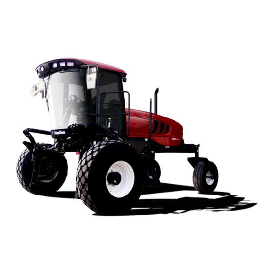
MacDon M105 Operator's Manual
Self-propelled windrower
Hide thumbs
Also See for M105:
- Operator's manual (209 pages) ,
- Assembly instructions manual (54 pages) ,
- Unloading and assembly instructions (53 pages)

Related Manuals for MacDon M105


Summary of Contents for MacDon M105
- Page 1 M105 Self-Propelled Windrower Operator’s Manual 169890 Revision A Original Instruction The harvesting specialists worldwide.
- Page 2 This manual contains instructions for SAFETY, OPERATION, and MAINTENANCE/SERVICE for the MacDon M105 Self-Propelled Windrower. Published July, 2014 California Proposition 65 Warning Diesel engine exhaust and some of its constituents are known to the State of California to cause cancer, birth defects, and other reproductive harm.
- Page 3 Declaration of Conformity Figure 1: Declaration of Conformity Continued on next page. 169890 Revision A...
- Page 4 Whole Body and Hand-Arm Vibration Levels The weighted root mean square acceleration, to which the whole body is subjected, ranges from 0.57 to 1.06 m/s as measured on a representative machine during typical operations and analyzed in accordance with ISO 5008. During the same operations, the weighted root means square hand-arm vibration was less than 1.45 m/s when analyzed in accordance with ISO 5349.
- Page 5 Introduction This manual contains information on the MacDon M105 Self-Propelled Windrower, which is designed to cut and lay in windrows a wide variety of grain, hay, and specialty crops. Windrowing allows starting the harvest earlier, protects the crop from wind damage, and gives you more flexibility in scheduling combine time.
- Page 6 List of Revisions At MacDon, we are continuously making improvements: occasionally these improvements impact product documentation. The following list provides an account of major changes from the previous version of this document. Summary of Change Location Added new safety sign locations.
- Page 7 Serial Number ® If you require MacDon technical assistance, please have the serial number recorded and ready, before you call. Record the model number, model year, and serial number of the windrower and engine on the lines below. The windrower serial number plate (A) is located on the left side of the main frame near the walking beam.
-
Page 9: Table Of Contents
TABLE OF CONTENTS Declaration of Conformity ........................i Whole Body and Hand-Arm Vibration Levels ..................ii Noise Levels ............................ii Introduction ............................. iii List of Revisions ..........................iv Serial Number ..........................v Safety ..............................1 Safety Alert Symbols........................1 Signal Words........................... 2 General Safety ..........................3 Maintenance Safety ......................... - Page 10 TABLE OF CONTENTS 3.14 Horn ............................. 53 3.15 Engine Controls and Gauges......................54 3.16 Windrower Controls ........................55 3.17 Header Controls ..........................56 3.17.1 Header Drive Switch....................... 56 3.17.2 Deck Shift Switch–Draper Header Option................. 56 3.17.3 Ground Speed Lever (GSL) Header Switches ................57 Display Selector Switch....................
- Page 11 TABLE OF CONTENTS Ingress/Egress ....................... 96 Driving Forward ......................97 Driving in Reverse ......................98 Spin Turning ........................98 Stopping ........................99 4.3.7 Adjusting Caster Tread Width....................100 4.3.8 Transporting the Windrower ....................101 Driving on the Road .......................101 Towing Header with Windrower..................104 Towing the Windrower (Emergency) ................
- Page 12 TABLE OF CONTENTS Setting Knife Speed (with Expansion Module MD #4666) ..........175 Setting Knife Speed (without Expansion Module MD #B4666)...........177 4.6.9 Deck Shift Control .........................178 Deck Shift ........................178 Operating with an A-Series Header ....................179 4.7.1 Auger Speed.........................179 Auger Speed on A30-D Headers..................179 Auger Speed on A40-D Headers..................180 4.7.2 Reel Speed...........................181...
- Page 13 TABLE OF CONTENTS Checking Steering Link Pivots ..................214 5.7.5 Neutral Start Switch.......................217 5.7.6 Heating, Ventilating, and Air Conditioning (HVAC) System ............218 Fresh Air Intake Filter.....................218 Return Air Cleaner/Filter....................219 Air Conditioning Condenser ....................221 Air Conditioning Evaporator ....................222 Air Conditioning (A/C) Compressor .................224 5.7.7 Engine..........................225 General Engine Inspection .....................225...
- Page 14 TABLE OF CONTENTS Operator’s Station Troubleshooting ....................335 Options and Attachments ........................337 Available Options and Attachments....................337 7.1.1 AM/FM Radio........................337 7.1.2 Anti-Shimmy Shocks for Casters ....................337 7.1.3 Automated Steering Systems ....................337 7.1.4 Booster Spring Kit (External) ....................337 7.1.5 Booster Spring Kit (Internal) ....................337 7.1.6 Draper Header Case Drain Kit....................338 7.1.7...
-
Page 15: Safety
1 Safety 1.1 Safety Alert Symbols This safety alert symbol indicates important safety messages in this manual and on safety signs on the windrower. This symbol means: • ATTENTION! • BECOME ALERT! • YOUR SAFETY IS INVOLVED! Carefully read follow safety message accompanying this symbol. -
Page 16: Signal Words
SAFETY 1.2 Signal Words Three signal words, DANGER, WARNING, and CAUTION, are used to alert you to hazardous situations. The appropriate signal word for each situation has been selected using the following guidelines: DANGER Indicates an imminently hazardous situation that, if not avoided, will result in death, or serious injury. WARNING Indicates a potentially hazardous situation that, if not avoided, could result in death, or serious injury. -
Page 17: General Safety
SAFETY 1.3 General Safety CAUTION The following are general farm safety precautions that should be part of your operating procedure for all types of machinery. Protect yourself • When assembling, operating, and servicing machinery, wear all the protective clothing and personal safety devices that COULD be necessary for the job at hand. - Page 18 SAFETY • Wear close fitting clothing and cover long hair. Never wear dangling items such as scarves or bracelets. • Keep all shields in place. Never alter or remove safety equipment. Make sure driveline guards can rotate independently of the shaft and can telescope freely. •...
-
Page 19: Maintenance Safety
SAFETY 1.4 Maintenance Safety To ensure your safety while maintaining the machine: • Review the operator’s manual and all safety items before operation and/or maintenance of the machine. • Place all controls in Neutral, stop the engine, set the park brake, remove the ignition key, and wait for all moving parts to stop before servicing, adjusting, and/or repairing. -
Page 20: Hydraulic Safety
SAFETY 1.5 Hydraulic Safety • Always place hydraulic controls Neutral before dismounting. • Make sure that all components in the hydraulic system are kept in good condition and clean. • Replace any worn, cut, abraded, flattened, or crimped hoses and steel lines. •... -
Page 21: Tire Safety
SAFETY 1.6 Tire Safety • Failure to follow proper procedures when mounting a tire on a wheel or rim can produce an explosion that may result in serious injury or death. Figure 1.14: Over-Inflated Tire • Do NOT attempt to mount a tire unless you have the proper training and equipment. -
Page 22: Battery Safety
SAFETY 1.7 Battery Safety WARNING • Keep all sparks and flames away from the batteries, as a gas given off by electrolyte is explosive. • Ventilate when charging in enclosed space. Figure 1.16: Safety around Batteries WARNING • Wear safety glasses when working near batteries. •... -
Page 23: Welding Precaution
High currents and voltage spikes associated with welding can cause damage to electronic components. Before welding on any part of the windrower or an attached header, disconnect all electronic module harness connections as well as the battery cables. Refer to your MacDon Dealer for proper procedures. 169890... -
Page 24: Engine Safety
• Do NOT bypass or disable the automatic shutoff circuits. The circuits are provided in order to help prevent personal injury. The circuits are also provided in order to help prevent engine damage. Refer to your MacDon Dealer for repairs and adjustments. • Inspect the engine for potential hazards. -
Page 25: Engine Electronics
SAFETY 1.9.2 Engine Electronics WARNING Tampering with the electronic system installation or the original equipment manufacturer (OEM) wiring installation can be dangerous and could result in personal injury or death and/or engine damage. WARNING Electrical Shock Hazard. The electronic unit injectors use DC voltage. The engine control module (ECM) sends this voltage to the electronic unit injectors. -
Page 26: Safety Signs
SAFETY 1.10 Safety Signs • Keep safety signs clean and legible at all times. • Replace safety signs that missing become illegible. • If original parts on which a safety sign was installed are replaced, be sure the repair part also bears the current safety sign. -
Page 27: Safety Sign Locations
SAFETY 1.11 Safety Sign Locations Figure 1.20: Safety Sign Locations (LH Side) A - MD #166450 Fan Shroud (Top) A - MD #166451 Fan Shroud (Middle) A - MD #166452 Fan Shroud (Bottom) B - MD #166425 LH of Step B - MD #166440 RH of Step C - MD #166466 LH Frame D - MD #166450 LH, Close to the Exhaust... - Page 28 SAFETY Figure 1.21: Safety Signs (LH Side) 169890 Revision A...
- Page 29 SAFETY Figure 1.22: Safety Sign Locations (RH Side) A - MD #166451 RH, Fan Shroud (Top) A - MD #166452 RH, Fan Shroud (Bottom) B - MD #174436 Center, Hydraulic Reservoir C - MD #166425 Traction Pump Mount D - MD #166457 Interior Post (Above Vent) D - MD #166234 Interior Post (Below Vent) D - MD #166462 Interior Post (Bottom) E - MD #166464 Radio Panel...
- Page 30 SAFETY Figure 1.23: Safety Signs (RH Side) 169890 Revision A...
-
Page 31: Interpreting Safety Signs
SAFETY 1.12 Interpreting Safety Signs In the safety sign explanations below, (a) refers to the top or left position panel, (b) refers to the bottom or right position of the safety decal depending on decal orientation. NOTE: If there are more than two panels in a decal, the lettering will continue downward or to the right, depending on decal orientation. - Page 32 SAFETY 3. MD #166438 a. Crushing hazard. b. DANGER • Rest header on ground or engage safety props before going under unit. Figure 1.26: MD #166438 4. MD #166439 a. Crushing hazard. b. DANGER • Rest header on ground or engage safety props before going under unit.
- Page 33 SAFETY 5. MD #166440 a. Loss of control hazard. b. CAUTION • To prevent machine damage and/or loss of control, it is essential that the machine be equipped such that weights are within the specified limits. Figure 1.28: MD #166440 6.
- Page 34 SAFETY 8. MD #166454 a. General hazard pertaining to machine operation and servicing. b. CAUTION To avoid injury or death from improper or unsafe machine operation: Read the operator’s manual and follow all safety instructions. If you do not have a manual, obtain one from your dealer.
- Page 35 SAFETY 10. MD #166456 a. Battery acid hazard. b. WARNING • Corrosive and poisonous battery acid. Acid can severely burn your body and clothing. Figure 1.33: MD #166456 169890 Revision A...
- Page 36 SAFETY 11. MD #166457 a. General hazard pertaining to machine operation and servicing. b. CAUTION To avoid injury or death from improper or unsafe machine operation: Read the operator’s manual and follow all safety instructions. If you do not have a manual, obtain one from your Dealer.
- Page 37 Figure 1.36: MD #166463 iii. If width of attached header impedes other vehicle traffic, remove header and install MacDon approved weight box. Refer to operator’s manual for safe procedure to tow header. 14. MD #166466 a.
- Page 38 SAFETY 15. MD #174436 a. High pressure oil hazard. b. WARNING Do not go near leaks. • High pressure oil easily punctures skin causing serious injury, gangrene, or death. • If injured, seek emergency medical help. Immediate surgery is required to remove oil. •...
- Page 39 SAFETY 17. MD #190546 a. Slippery surface. b. WARNING Do not place foot. • Do not use this area as a step or platform. • Failure to comply could result in serious injury or death. Figure 1.40: MD #190546 169890 Revision A...
-
Page 41: Description
It is used to change header angle. CGVW Combined vehicle gross weight. D-Series header MacDon rigid draper header. Engine control module. Finger tight is a reference position where sealing surfaces or components are Finger tight making contact with each other and the fitting has been tightened to a point where... - Page 42 DESCRIPTION Term Definition O-ring boss: a style of fitting commonly used in port opening on manifolds, pumps and motors. O-ring face seal: a style of fitting commonly used for connecting hoses and tubes. ORFS This style of fitting is also commonly called ORS, which stands for O-ring seal. Power Take-Off.
-
Page 43: Specifications
DESCRIPTION 2.2 Specifications ENGINE Type Cummins QSB - 4.5L 4 Cylinder Turbo Diesel. B20 Biodiesel Approved. Displacement 275 cu. in. (4.5 L) Rated 110 hp (81 kW) @ 2,500 rpm Power Peak 115 hp (86 kW) @ 2300 rpm Bore 4-21/100 in. - Page 44 DESCRIPTION SYSTEM CAPACITIES Fuel Tank 97 US Gallons (367 L) Cooling 6.6 US Gallons (25 L) Hydraulic Reservoir 11.5 US Gallons (44 L) HEADER DRIVE Single Piston Pump Gear Pump Gear Pump Hydraulic, Type Gear Gear Load Sensing Control Displacement (manually adjusted 0–3 cu.
- Page 45 DESCRIPTION Air Conditioning 28,280 Btu/h (8288 W) Electrical Outlets One Live, One on Ignition, One Live/Keyed Mirrors Two Outside (Field) Radio Two Speakers and Antenna Factory Installed. Radio Dealer Installed SYSTEM MONITORING Ground (mph or km/h), Engine (rpm), Conveyor (Ref. No.), Knife (spm) Speeds (Optional), Reel (rpm or mph/km/h) (Optional) Header...
-
Page 46: Windrower Dimensions
DESCRIPTION 2.3 Windrower Dimensions Figure 2.2: Windrower Dimensions – Forward A - Drive Tire Tread B - Drive Tire Hubs C - Drive Tires F - 45-3/4 in. (1160 mm) G - 133 in. (3378 mm) H - 158-5/16 in. (4022 mm) J - 207-7/8 in. - Page 47 DESCRIPTION Figure 2.3: Windrower Dimensions – Reverse D - Caster Tire Tread E - Caster Tire Casters K - 120-9/16 in. (3064 mm) L - 186-7/8 in. (4747 mm) Table 2.2 Caster Tires Tread (D) Casters (E) Tire Size Wheel Position in.
-
Page 48: Component Location
DESCRIPTION 2.4 Component Location Figure 2.4: Front View A - Header Lift Leg B - Header Float Springs C - Operator’s Station D - Windshield Wiper E - Turn Signal / Hazard Lights F - Field/Road Lights G - Handholds H - Mirror J - Door K - Maintenance Platform... -
Page 49: Operator's Station
3 Operator’s Station The operator’s station is designed to provide access to windrower controls and operator amenities. 3.1 Operator Console The console contains controls to operate the windrower, as well as amenities for the Operator. Figure 3.1: Operator Console A - Ignition B - Engine/Windrower Cab Display Module (CDM) C - Header Controls (GSL, Header Drive Switch, Deck Shift) D - Ground Speed Controls... -
Page 50: Operator Presence System
OPERATOR’S STATION 3.2 Operator Presence System The Operator Presence System is a safety feature designed to deactivate or alarm selected systems when the Operator is not seated at the operator’s station. These systems include: • Header Drive • Engine and Transmission 3.2.1 Header Drive •... -
Page 51: Operator's Seat Adjustments
OPERATOR’S STATION 3.3 Operator’s Seat Adjustments The operator’s seat has several adjustments. Refer to the following for the location and description of each adjustment. A – Armrest Up or Down • Raise armrest (A) for easier access to the seat. •... -
Page 52: Training Seat (Optional)
OPERATOR’S STATION 3.4 Training Seat (Optional) A wall-mounted fold-up training seat complete with seat belt is provided. WARNING • The training seat is provided for an experienced Operator of the machine when a new Operator is being trained. • The training seat is NOT intended as a PASSENGER SEAT or FOR USE BY CHILDREN. USE THE SEAT BELT whenever operating the machine or riding as a Trainer. -
Page 53: Seat Belts
OPERATOR’S STATION 3.5 Seat Belts The windrower is equipped with a seat belt on the operator’s and trainer’s seats. WARNING The seat belt can help ensure your safety if it is used and maintained. • Before starting the engine, securely fasten your seat belt. Ensure that anyone occupying the trainee’s seat is secured by a seat belt as well. -
Page 54: Steering Column Adjustment
OPERATOR’S STATION 3.6 Steering Column Adjustment The steering column can be adjusted to suit each particular Operator and for easier entry to and exit from the seat. To adjust the steering column: 1. Hold onto steering wheel, step on lever (A), and move steering wheel up or down to desired position. -
Page 55: Lighting
OPERATOR’S STATION 3.7 Lighting The field and road light switches are located on a panel in the cab headliner. Figure 3.7: Light Switches A - Field and Road/Transport Lights (FIELD / OFF / ROAD) B - Low or High Beams for Road/Transport Lights (LOW / HIGH) C - Beacons on Cab Roof (If Installed) (OFF / ON) 3.7.1 Field Lighting The following lights are ON/functional when the switch is in... -
Page 56: Road Lighting
OPERATOR’S STATION Figure 3.9: Front View - Field Lights A - Field Lights Figure 3.10: Rear View A - Flood Lights B - Swath Lights - HIGH / LOW 3.7.2 Road Lighting The following lights are ON/functional when the switch is in the ROAD position: •... -
Page 57: Beacon Lighting
OPERATOR’S STATION Figure 3.12: Front View A - Road Lights B - Turn Signals / Hazards - Amber Figure 3.13: Rear View A - Turn Signals / Hazards - Amber B - SMV Sign C - Red Tail Lights 3.7.3 Beacon Lighting MD #B5582 Beacon lighting is an optional feature inside North America but comes standard on windrowers exported outside North America. -
Page 58: Optional Hid Auxiliary Lighting (If Installed)
OPERATOR’S STATION The beacon lights are functional when the ignition and the beacon switches are ON. Figure 3.14: Beacon Light Switch The amber warning beacons (A) MUST be used when driving on the road where required by law. Figure 3.15: Optional Beacon Lights 3.7.4 Optional HID Auxiliary Lighting (If installed) Two optional High Intensity Discharge (HID) lights (MD #B5596) provide additional lighting during field operation. -
Page 59: Windshield Wiper
OPERATOR’S STATION 3.8 Windshield Wiper The ON-OFF windshield wiper control is located in the cab headliner. Figure 3.17: Switch in Cab Headliner Figure 3.18: Wiper in Park Position 169890 Revision A... -
Page 60: Rear View Mirrors
OPERATOR’S STATION 3.9 Rear View Mirrors Two adjustable outside mounted mirrors (A) provide rear view vision. The mirror/light assembly is designed to fold backwards if accidentally struck either during normal operation or by another machine. A detent-type lock keeps it in place. Figure 3.19: Mirrors 169890 Revision A... -
Page 61: Cab Temperature
OPERATOR’S STATION 3.10 Cab Temperature The cab environment is controlled by a climate control system that provides clean air-conditioned or heated air for the Operator. The heater/evaporator/blower assembly is located under the cab floorboard and is accessible from beneath the windrower. 3.10.1 Heater Shut-Off A shut-off valve (A) at the engine allows the cab heater to be isolated from the engine coolant. -
Page 62: Controls
OPERATOR’S STATION 3.10.3 Controls A – Temperature Control Dial controls cab temperature. • Clockwise: Increases temperature. • Counterclockwise: Decreases temperature. B – Blower Switch controls the blower speed. • OFF / LOW / MEDIUM / HIGH C – Air Conditioning Switch controls the A/C system. •... -
Page 63: Interior Lights
OPERATOR’S STATION 3.11 Interior Lights Two interior lights are installed in the cab headliner. A low intensity LED light (A) is located directly overhead to provide ambient lighting if desired, and functions only when the ROAD/FIELD light switch is ON. An ON-OFF switch is located on the light. -
Page 64: Operator Amenities
OPERATOR’S STATION 3.12 Operator Amenities The operator’s station includes the following amenities: Operator’s Console A - Cigarette Lighter B - Ashtray/Cupholders C - Utility Tray D - Auxiliary Power E - Data Link Receptacle F - Live/Switchable/Ground - 20 A G - Manual Storage Case Figure 3.25: Operator Amenities 169890... -
Page 65: Radio
Unloading and Assembly Instruction for North America (MD #169893) for installation procedures Figure 3.27: Antenna Mount Instructions not sold separately. Access unload and assembly instructions on the MacDon corporate website www.macdon.com. Instructions not sold separately. Access unload and assembly instructions on the MacDon corporate website www.macdon.com... - Page 66 OPERATOR’S STATION To make your own mount, refer to dimensions template. Use 11 GA. or 3.0 mm steel sheet. Figure 3.28: Template for Antenna Mount 169890 Revision A...
-
Page 67: Horn
OPERATOR’S STATION 3.14 Horn The horn is activated by pushing button (A) located beside the ignition key. Sound the horn three times prior to starting the engine. Figure 3.29: Operator Console The horn (A) is located outside the cab on the rear right-hand corner of the cab, under the roof. -
Page 68: Engine Controls And Gauges
OPERATOR’S STATION 3.15 Engine Controls and Gauges All engine controls are conveniently located on the operator’s console. Refer to the illustration for the location and the following for a description of each. A – Ignition Switch • ACC: Fully counterclockwise •... -
Page 69: Windrower Controls
OPERATOR’S STATION 3.16 Windrower Controls Console Controls: A – TURN SIGNALS activate turn signals on windrower and header. • Push-ON / Push-OFF B – GROUND SPEED LEVER (GSL) controls speed and direction of movement. • F: Forward • N: NEUTRAL •... -
Page 70: Header Controls
OPERATOR’S STATION 3.17 Header Controls All header controls are conveniently located on the operator’s console and on the ground speed lever (GSL) handle. NOTE: Some controls are optional equipment and may not be present in your unit. Some controls may be installed, but will be nonfunctional for certain headers. -
Page 71: Ground Speed Lever (Gsl) Header Switches
OPERATOR’S STATION 3.17.3 Ground Speed Lever (GSL) Header Switches The GSL (A) contains switches for the header functions that are most often adjusted while in operation to suit changing crop conditions. All are momentary-type switches. Figure 3.36: GSL NOTE: A decal (B) identifying switch functions is located on the cab post above the operator’s console. -
Page 72: Display Selector Switch
OPERATOR’S STATION Display Selector Switch The display selector switch (A) selects and displays the settings in the cab display module (CDM) top line read-out (A) for each of the header controls. Press switch (B) to scroll through settings. Figure 3.38: GSL Reel Position Switches NOTE: Reel position switches work on draper headers only. -
Page 73: Header Position Switches
OPERATOR’S STATION Header Position Switches Press and hold switch at location shown to move header up or down and to change the angle of the header relative to the ground. Release switch at desired position. NOTE: Refer to the section in this manual that is specific to your header for detailed switch operating modes. -
Page 74: Cab Display Module (Cdm)
OPERATOR’S STATION 3.18 Cab Display Module (CDM) 3.18.1 Engine and Windrower Functions Figure 3.42: CDM Engine and Windrower Functions A – Engine rpm. B – Ground Speed: mph or kph. C – DISPLAY: Engine/windrower functions. D – HAZARD WARNING LIGHTS switch: Activates hazard warning lights, cancels turn signal. E –... -
Page 75: Header Functions
OPERATOR’S STATION 3.18.2 Header Functions Figure 3.43: Cab Display Module A - Display B - Select Switch C - Reel/Auger Speed Controls (Auger Header) D - Draper Speed Control (Draper Header) E - Header Index Switch (Options Required) F - Return to Cut Height Switch •... -
Page 76: Operating Screens
OPERATOR’S STATION 3.18.3 Operating Screens The cab display module (CDM) and the windrower control module (WCM) provide information on several functions for the engine, header, and windrower. The information displayed in various operating modes is described in the following sections. Figure 3.44: CDM Operating Screen A - Display Selector for Upper Line B - Display... -
Page 77: Engine Running, Header Disengaged
OPERATOR’S STATION Engine Running, Header Disengaged Scroll through display with cab display module (CDM) switch or ground speed lever (GSL) switch. Display (lower or upper line) Description #####.# ENGINE HRS Total engine operating time. #####.# UNIT HRS Total windrower operating time. #####.# HEADER HRS Total header operating time. -
Page 78: Engine Running, Header Engaged, Draper Header, Index Switch Off
OPERATOR’S STATION Display (Lower or Upper Line) Description ###### TOTAL ACRES Total area cut by machine. ###### TOTAL HECT (if Metric) ##.## REEL RPM Reel rotational speed. Optional ##.## REEL SENSOR (Flashing) Sensor disabled. ##.# AUGER SPEED Auger rotational speed (4.7–9.9). #### KNIFE SPEED Knife speed In strokes per minute. -
Page 79: Engine Running, Header Engaged, Draper Header, Index Switch On
OPERATOR’S STATION Display (lower or upper line) Description #### KNIFE SPEED Knife speed In strokes per minute. Optional. #### KNIFE SENSOR (flashing) Sensor Disabled. ##.# HEADER HEIGHT Distance setting (00.0–10.0) between cutterbar and ground. ##.# HEADER SENSOR (flashing) Sensor Disabled. ##.# HEADER ANGLE Header Angle setting (00.0–10.0) relative to ground. -
Page 80: Miscellaneous Operational Information
OPERATOR’S STATION Display (lower or upper line) Description ##.# HEADER ANGLE Angle setting (00.0–10.0) header relative to ground. Optional ##.# HEADER SENSOR (flashing) Sensor Disabled. Engine electrical system operating voltage. ##.# VOLTS FUEL |■■■■|■■■■| Level of fuel in tank. ENGINE TEMP ### °F Engine coolant temperature. -
Page 81: Cab Display Module (Cdm) Warning/Alarms
OPERATOR’S STATION 3.18.4 Cab Display Module (CDM) Warning/Alarms The CDM displays warnings and sounds alarms to notify of abnormal windrower status at startup when the ignition is turned ON, and at engine operating speeds above 500 rpm. Engine Warning Lights Figure 3.45: CDM Engine Warning Lights A - Engine Pre-Heat B - Water in Fuel... -
Page 82: Display Warnings And Alarms
OPERATOR’S STATION Display Warnings and Alarms Informs Operator of abnormal windrower conditions. Figure 3.46: CDM Display Warnings and Alarms Display (A) Flashing Alarm Tone Description Interlock switch not closed with Beeps at 2 per second until key ON / engine OFF: GSL not in CENTER STEERING corrected N-DETENT or steering wheel not... - Page 83 OPERATOR’S STATION Display (A) Flashing Alarm Tone Description Low hydraulic oil level, header shuts down automatically if Continuous loud tone for 5 seconds: if condition not engaged: HEADER DRIVE switch LOW HYDRAULIC OIL rectified, single loud tone every must be moved to OFF position 5 minutes and then to ON position to restart the header...
-
Page 84: Cab Display Module (Cdm) Programming
OPERATOR’S STATION 3.18.5 Cab Display Module (CDM) Programming Figure 3.47: CDM A - Side Display B - Main Display C - Select Switch D - Menu Item Scroll Forward E - Menu Item Scroll Backward F - Program Switch SIDE DISPLAY: displays software revision status. •... -
Page 85: Programming Guidelines
OPERATOR’S STATION NOTE: Contact your MacDon Dealer for information regarding software updates to the electronic modules. Your Dealer will have the necessary interface tools and access to the latest software upgrades. Proceed as follows to program the CDM: IMPORTANT: Header must be attached to the windrower so that the CDM can detect the type of header (Header ID) and adjust the programming mode accordingly. -
Page 86: Detailed Programming Menu Flow Chart
Detailed Programming Menu Flow Chart, page 72 for each menu item. NOTE: Contact your MacDon dealer for information about software updates to the electronic modules. Your Dealer will have the necessary interface tools and access to the latest software upgrades Detailed Programming Menu Flow Chart The programming menu flow chart is current for cab display module (CDM) software C107 and windrower control... - Page 87 OPERATOR’S STATION 169890 Revision A...
- Page 88 OPERATOR’S STATION 169890 Revision A...
- Page 89 OPERATOR’S STATION 169890 Revision A...
- Page 90 OPERATOR’S STATION 169890 Revision A...
- Page 91 OPERATOR’S STATION 169890 Revision A...
-
Page 92: Operating Information Screens
OPERATOR’S STATION Operating Information Screens 169890 Revision A... -
Page 93: Engine Error Codes
OPERATOR’S STATION 3.18.6 Engine Error Codes The cab display module (CDM) displays error codes when there is a fault with one of the several sensors that monitor and control engine operation, to assist the Operator or Technician in locating a specific problem with engine operation. -
Page 95: Operation
4 Operation 4.1 Owner/Operator Responsibilities CAUTION • It is your responsibility to read and understand this manual completely before operating the windrower. Contact your Dealer if an instruction is not clear to you. • Follow all safety messages in the manual and on safety signs on the machine. •... -
Page 96: Symbol Definitions
OPERATION 4.2 Symbol Definitions The following symbols are used to depict functions or reactions at the various instruments and controls. Learn the meaning of these symbols before operating the windrower. 4.2.1 Engine Functions These are the symbols that are used on the console. Figure 4.1: Engine Function Symbols A - Electrical Power –... -
Page 97: Windrower Operating Symbols
OPERATION 4.2.2 Windrower Operating Symbols These are the symbols used on the console for windrower operation. Figure 4.2: Windrower Operating Symbols A - Turn Signals B - Hazard Warning Lights C - Forward D - Neutral E - Reverse F - Headlights Low Beam / Road Lights G - Headlights High Beam / Road Lights H - Work Light J - Lighter... -
Page 98: Header Functions
OPERATION 4.2.3 Header Functions Figure 4.3: Header Function Symbols A - Program B - Display Select C - Header Index D - Reel Speed E - Return to Cut F - Reel Rearward G - Reel Forward H - Header Tilt Up J - Header Tilt Down K - Conveyor/Auger Speed L - Header Down... -
Page 99: Operating The Windrower
OPERATION 4.3 Operating the Windrower 4.3.1 Operational Safety CAUTION Follow these safety precautions: • Wear close fitting clothing and protective shoes with slip resistant soles. • Remove foreign objects from the machine and surrounding area. • Carry with you any protective clothing and personal safety devices that COULD be necessary through the day. -
Page 100: Break-In Period
OPERATION 4.3.2 Break-In Period The windrower is ready for normal operation. However there are several items to check and watch out for during the first 150 hours. In addition to the following, perform the items specified in Break-In Inspections, page 313. -
Page 101: Air Conditioning Compressor Coolant Cycling
OPERATION d. Adjust tension on air conditioning (A/C) compressor belt. Refer to Tensioning Air Conditioner (A/C) Compressor Belt, page 257. e. Distribute A/C refrigerant by cycling A/C switch. Refer to Air Conditioning Compressor Coolant Cycling, page Check the entire A/C system for leakage at the beginning of each season. 2. -
Page 102: Engine Operation
OPERATION 4.3.5 Engine Operation Starting the Engine DANGER • Avoid possible injury or death from a runaway machine. • This machine has safety devices which allow the engine to start only when the ground speed lever is in N-DETENT, the steering wheel is locked in the NEUTRAL position, and the header drive switch is in the OFF position. - Page 103 OPERATION 2. Move ground speed lever (GSL) into N-DETENT (B). 3. Turn steering wheel until it locks. It may be possible to move the steering wheel slightly in the locked position. IMPORTANT: Do NOT attempt to force the wheel out of locked position as damage to the traction system may occur.
- Page 104 OPERATION Cold Start Engine temperature below 40°F (5°C) WARNING If starter engages with steering wheel unlocked, ground speed lever (GSL) out of NEUTRAL, or header clutch engaged, DO NOT START ENGINE. See your Dealer. 1. Set throttle (A) to START position - fully back (low idle). 2.
-
Page 105: Engine Warm-Up
OPERATION Engine Warm-Up Allow engine to run with throttle lever (A) at or near low idle position until engine temperature reading on display (B) reaches approximately 100°F (40°C). NOTE: Scroll through cab display module (CDM) for engine temperature. Figure 4.11: Operator Console Engine Intermediate Speed Control (ISC) Engine ISC is useful when operating loads are reduced such as in light crop conditions that do not require the maximum engine rpm. -
Page 106: Filling Fuel Tank
OPERATION Filling Fuel Tank Fill fuel tank daily, preferably at the end of the day’s operation to help prevent condensation in the tank. DANGER Stop engine and remove key from ignition before leaving operator's seat for any reason. A child or even a pet could engage an idling machine. -
Page 107: Engine Temperature
OPERATION Engine Temperature The normal engine operating temperature range is 180–225°F (82–107°C). If the temperature exceeds 230°F (110°C), an ongoing intermittent tone will be heard and the cab display module (CDM) (A) will flash “ENGINE TEMP”. Stop the engine immediately and determine cause. The tone will stop and the CDM (A) will return to normal when the temperature drops below 225°F (107°C). -
Page 108: Engine Warning Lights
OPERATION Engine Warning Lights Four engine warning lights indicate abnormal engine conditions. Engine warning lights should NOT be illuminated under normal operating conditions. • ENGINE PRE-HEAT (A) illuminates yellow. Wait to start engine. • WATER IN FUEL (B) illuminates yellow. Service recommended. - Page 109 OPERATION CAUTION • With the engine running, moving the ground speed lever out of N-DETENT unlocks steering. Any movement of steering wheel will then cause the machine to move, even if the ground speed lever has not been moved forward or rearward from the NEUTRAL position. •...
-
Page 110: Ingress/Egress
OPERATION Ingress/Egress CAUTION To provide more secure hand and foot mobility, preventing slipping and possible injury, ALWAYS face the windrower and use the hand rail when dismounting (or mounting). • NEVER attempt to get on or off a moving windrower. Before leaving the operator's seat for any reason: •... -
Page 111: Driving Forward
The windrower can be equipped with an automatic steering system for use in the field. An automated steering system is available as an option and can be installed by a MacDon Dealer. The GSL has been pre-wired at the factory with a switch. Also refer to 7.1.3 Automated Steering Systems, page... -
Page 112: Driving In Reverse
OPERATION Driving in Reverse WARNING Back up slowly. Steering is opposite to normal when reversing. Hold steering wheel at the bottom and turn wheel in direction you want the rear of the machine to travel. 1. Set ground speed range switch (A) to 1 (field speed). 2. -
Page 113: Stopping
OPERATION 1. Move the ground speed lever (GSL) (A) out of N-DETENT towards the seat and hold. 2. Slowly turn the steering wheel in the desired direction of turn. The windrower will pivot between the drive wheels. 3. To increase the turn radius, slowly move the GSL away from NEUTRAL. -
Page 114: Adjusting Caster Tread Width
OPERATION 4.3.7 Adjusting Caster Tread Width The rear casters can be adjusted to a narrow tread width to allow loading and shipping without having to remove them. A narrow tread width also suits smaller headers by allowing more space to the uncut crop and provides more manoeuvrability around poles, irrigation inlets, or other obstacles. -
Page 115: Transporting The Windrower
• Obey all highway traffic regulations in your area. Use pilot vehicles in front and rear of windrower if required by law. • Use slow moving vehicle emblem and flashing warning lights unless prohibited by law. • If width of attached header impedes other vehicle traffic, remove header and install a MacDon approved weight box. 169890... - Page 116 OPERATION WARNING Do NOT drive windrower on a road or highway at night, or in conditions that reduce visibility, such as fog or rain. The width of the windrower may not be apparent under these conditions. CAUTION Operate both steering wheel and ground speed lever slowly for familiarization. Remember that steering is more sensitive when ground speed-range control switch is set to ROAD position - 2.
- Page 117 • Set GROUND SPEED RANGE switch to 1 - field speed. With header removed, steering control is reduced if weight is not added to drive wheels. If you must drive the windrower without header or MacDon weight system: • Operate in 1 – field speed range.
-
Page 118: Towing Header With Windrower
Towing Header with Windrower The windrower can be used to tow a MacDon draper header that has the optional slow speed transport option installed, PROVIDED the optional weight box is installed on the windrower or an approved header transporter with weight transfer to the lift arms. - Page 119 OPERATION Converting from Field to Transport Mode DANGER Stop engine and remove key from ignition before leaving operator's seat for any reason. A child or even a pet could engage an idling machine. DANGER To avoid bodily injury from fall of raised header, always engage safety props when working on or around raised header, and before going under header for any reason.
- Page 120 OPERATION 7. Remove float pin from engaged position (A) and insert in storage location (B). Secure with lynch pin. Figure 4.35: Lift Arms 8. Remove pins (A) from lower end of lift linkages. NOTE: Pins (A) are also used to secure weight box to windrower linkage.
- Page 121 OPERATION Disconnect the center-link as follows: Hydraulic Link 13. If using hydraulic link, disconnect the center-link as follows: a. Pull up on latch (A), and position latch into notch (B) on top of hook. b. Release safety props on the header lift cylinders (4.4.1 Header Safety Props, page 117).
- Page 122 OPERATION 17. Drive windrower so that windrower lift arms are located in the weight box pockets. 18. Raise lift arms slightly. 19. Stop engine, and remove key. 20. Install locking pins (A) into pockets and through windrower header lift linkages. Secure with hairpin. NOTE: Pins (A) were previously removed from the header lift linkage lower end.
- Page 123 OPERATION The optional M105 transport drawbar (MD #B5411) mounts to the walking beam and provides approximately 12 in. (300 mm) of fore-aft movement to ease the attachment of a towed implement. Refer to 7.1.18 Transport Drawbar, page for more information.
- Page 124 OPERATION 27. If the tow-bar (A) is TOO CLOSE to the windrower: a. Remove pin (B), lower the drawbar support (C) until the tow-bar clevis aligns, and then install the drawbar pin (D). b. Start engine, and gently drive the windrower forward until the drawbar support pivots up to transport position.
- Page 125 OPERATION 29. At the drawbar, connect the tow-bar harness plug (A) to the receptacle on the windrower. Figure 4.47: Towing Harness 30. At the LH float spring tower, attach connector (A) on windrower harness to towing harness receptacle (B). Figure 4.48: Towing Harness 31.
- Page 126 OPERATION 2. Disconnect electrical harness at connector (B) from windrower and store harness (A) on weight box. Figure 4.49: Electrical Harness 3. Disconnect electrical harness (A) from windrower, and store harness on tow-bar. Figure 4.50: Electrical Connector 4. Undo lock (A), remove safety chain (B) from drawbar, and remove clevis pin (C).
- Page 127 OPERATION 5. Move tow-bar off drawbar. 6. At rear of windrower, remove pins (A), lift drawbar support (B) to horizontal position, and reinstall pins (a) as shown. 7. Alternative drawbar (C) is used for attaching a tow-bar behind swath roller. IMPORTANT: Do NOT use alternative drawbar for any other purpose.
-
Page 128: Towing The Windrower (Emergency)
OPERATION 9. Remove pins (A) securing lift linkages to weight box, and retain pins for attaching header to windrower. 10. Start engine, lower weight box onto blocks, and back away. 11. Attach header to windrower. Refer to 4.5.1 Attaching a D-Series Header, page 131. -
Page 129: Final Drives
OPERATION WARNING With final drives disengaged, the windrower may roll on a sloped surface. Before disengaging final drives, attach windrower to towing vehicle. After towing, engage drives and ensure ground speed lever (GSL) is in N-DETENT before detaching from towing vehicle. Figure 4.57: Correct Towing Procedure IMPORTANT: •... - Page 130 OPERATION CAUTION Never operate engine in a closed building. Proper ventilation is required to avoid exhaust gas hazards. CAUTION Remember when working around storage batteries that all of the exposed metal parts are live. Never lay a metal object across the terminals because a spark and short circuit will result. 1.
-
Page 131: Operating With A Header
OPERATION 4.4 Operating with a Header The M105 Self-Propelled Windrower is designed to use the MacDon A-Series Auger Header, and D65 Rigid Draper Header (up to 35-foot), with or without a Hay Conditioner. This section describes the attachment and detachment procedures and operating instructions for these header types. - Page 132 OPERATION 3. Pull lever (A) and rotate toward header to lower safety prop (B) onto cylinder. Repeat for opposite cylinder. Figure 4.60: Safety Prop 4. To disengage safety props and for storage, turn lever (A) away from header to raise safety prop until lever locks into vertical position.
-
Page 133: Header Float
OPERATION 4.4.2 Header Float Float is intended for cutting crops that require the cutterbar to be in contact with the ground. Optimum float is for the cutterbar to maintain contact with the ground with minimum bouncing and scooping or pushing soil. The machine will perform best with minimum extra weight on the header. -
Page 134: Checking Float
OPERATION Checking Float Figure 4.62: Cab Display Module (CDM) Float Adjustment A - CDM Display B - Header Tilt Down C - Header Tilt Up D - Header Up E - Header Down Check header float as follows: DANGER Stop engine and remove key from ignition before leaving operator's seat for any reason. A child or even a pet could engage an idling machine. -
Page 135: Levelling The Header
OPERATION Adjusting Float Using Drawbolts Float adjustment uses drawbolts to change the tension on the springs in the lift linkages. If necessary, adjust the float with the drawbolts as follows: CAUTION Check to be sure all bystanders have cleared the area. 1. - Page 136 OPERATION If the header is not level, perform the following checks prior to adjusting the levelling linkages. NOTE: The float springs are NOT used to level the header. • Raise header to full height, and keep HEADER UP switch pressed to ensure lift cylinders are phased. •...
- Page 137 OPERATION 5. Lower header onto blocks so that member (A) lifts off link (B) on both sides. 6. Stop engine and remove key. Figure 4.67: Lift Linkage 7. On high side, remove nut, washer, and bolt (A) that attaches shims (B) to link. 8.
-
Page 138: Header Drive
The header angle can be hydraulically adjusted from the cab without shutting down the windrower. A readout on the cab display module (CDM) allows you to establish settings for each crop condition. This feature requires that the optional expansion module MD #B4666 be installed, either at the factory or at your MacDon Dealer. 169890... - Page 139 OPERATION IMPORTANT: • Changing header angle will affect flotation slightly because it has the effect of making the header lighter or heavier. • To prevent excessive guard breakage when conditions are not suited to heavier float (e.g., rocky or wet), do NOT use the TILT CONTROL “on the go”.
-
Page 140: Checking Self-Locking Center-Link Hook
OPERATION Checking Self-Locking Center-Link Hook Periodically check the operation of the hook locking mechanism and ensure that it is working properly as follows: 1. If header is attached to windrower, disconnect center-link hook from header by pulling up on handle (A) to release the locking device and then lifting the hook off the header pin. -
Page 141: Cutting Height
OPERATION 4.4.6 Cutting Height Figure 4.75: Operator Console A - Display B - Header Up C - Header Down D - Display Selector Cutting height is adjusted by raising or lowering the header with the HEADER UP (B) or HEADER DOWN (C) switches on the ground speed lever (GSL). -
Page 142: Programming Return To Cut Feature
OPERATION Programming Return to Cut Feature Figure 4.76: Operator Console A - Return to Cut B - Header Up C - Header Down D - Display E - Header Tilt Up F - Header Tilt Down Program the RETURN TO CUT (RTC) feature as follows: IMPORTANT: To enable the RTC header tilt feature, the hydraulic center-link and expansion module options must be installed. -
Page 143: Using Return To Cut Feature
OPERATION Using Return to Cut Feature Figure 4.77: Operator Console A - Return to Cut B - Header Up C - Header Down D - Display E - Header Tilt Up F - Header Tilt Down Use the RETURN TO CUT feature as follows: IMPORTANT: Ensure the header is engaged and the RETURN TO CUT switch (A) is illuminated. -
Page 144: Swath Roller Operation
OPERATION 4.4.7 Swath Roller Operation Refer to the operating instructions that are provided with an optional Swath Roller kit. Refer to 7.1.15 Swath Roller, for more information. page 339 169890 Revision A... -
Page 145: Attaching And Detaching Headers
OPERATION 4.5 Attaching and Detaching Headers 4.5.1 Attaching a D-Series Header Refer to the procedure that is appropriate for the center-link installed on the windrower: • Attaching a D-Series Header: Hydraulic Center-Link, page 131 • Attaching a D-Series Header: Mechanical Center-Link, page 136 Attaching a D-Series Header: Hydraulic Center-Link NOTE: This topic assumes that draper header boots have already been attached to the windrower lift linkage. - Page 146 OPERATION 3. If necessary, relocate the pin (A) at the frame linkage as required to raise the center-link (B) so that the hook (B) is above the attachment pin on the header. IMPORTANT: If the center-link is too low, it may contact the header as the windrower approaches the header for hookup.
- Page 147 OPERATION 8. Push down on rod end of link cylinder (B), until hook engages pin on header and is locked. IMPORTANT: Hook release must be down to enable self-locking mechanism. If the release is open (up), manually push it down after hook engages header pin. 9.
- Page 148 OPERATION 11. Engage safety props on both lift cylinders as follows: a. Stop engine and remove key from ignition. b. Pull lever (A) and rotate toward header to release and lower the cylinder stop (B) onto cylinder. c. Repeat for the opposite lift cylinder. Figure 4.85: Cylinder Stop 12.
- Page 149 OPERATION 14. Remove clevis pin from storage position (B) in linkage and insert in hole (A) to engage float springs. Secure with hairpin. Figure 4.87: Header Lift Linkage 15. Disengage safety prop by turning lever (A) downward to release and lower stop until lever locks into vertical position.
-
Page 150: Attaching A D-Series Header: Mechanical Center-Link
OPERATION 19. Connect header drive hoses (A) and electrical harness (B) to header. Refer to the draper header operator’s manual. Figure 4.90: Header Drive Hoses and Harness 20. Connect reel hydraulics (A) at right-hand side of windrower. Refer to the draper header operator’s manual. - Page 151 OPERATION 1. Remove the hairpin (A) from pins (B) and remove the pins from header legs. CAUTION Check to be sure all bystanders have cleared the area. Figure 4.92: Header Leg 2. Start engine and activate HEADER DOWN button (A) on the ground speed lever (GSL) to fully retract header lift cylinders.
- Page 152 OPERATION 6. Loosen nut (A) and rotate barrel (B) to adjust length so that the link lines-up with header bracket. 7. Install clevis pin (C) and secure with cotter pin (D). 8. Adjust link to required length for proper header angle by rotating barrel (B).
- Page 153 OPERATION 10. Engage safety props on both lift cylinders as follows: a. Stop engine and remove key from ignition. b. Pull lever (A) and rotate toward header to release and lower the safety prop (B) onto cylinder. c. Repeat for the opposite lift cylinder. Figure 4.97: Cylinder Stop 11.
- Page 154 OPERATION 13. Remove clevis pin from storage position (B) in linkage and insert in hole (A) to engage float springs. Secure with hairpin. Figure 4.99: Header Lift Linkage 14. Disengage safety prop by turning lever (A) downward to release and lower stop until lever locks into vertical position.
-
Page 155: Detaching A D-Series Header
OPERATION 18. Connect header drive hoses (A) and electrical harness (B) to header. Refer to the draper header operator’s manual. Figure 4.102: Header Drive Hoses and Harness 19. Connect reel hydraulics (A) at right-hand side of windrower. Refer to the draper header operator’s manual. -
Page 156: Detaching A D-Series Header: Hydraulic Center-Link
OPERATION Detaching a D-Series Header: Hydraulic Center-Link To detach a D-Series header from an M-Series windrower equipped with a hydraulic center-link, follow these steps: DANGER Stop engine and remove key from ignition before leaving operator's seat for any reason. A child or even a pet could engage an idling machine. - Page 157 OPERATION 5. Remove the pin (B) by removing the hairpin (A) from header leg on both sides. 6. Lower header stand (D) by pulling spring loaded pin (C). Release spring pin to lock stand. Figure 4.106: Header Stands 7. Remove clevis pin from location (A) to disengage float springs and insert in storage hole (B).
- Page 158 OPERATION 9. Disconnect header drive hydraulics (A) and electrical harness (B) from header and store in support on windrower left cab-forward side. Refer to the draper header operator’s manual for further information. Figure 4.109: Header Drive Hydraulics 10. Disconnect reel hydraulics (A) from header and store on bracket at windrower left cab-forward side.
-
Page 159: Detaching A D-Series Header: Mechanical Center-Link
OPERATION 12. Disconnect center-link by lifting release (B) and lift hook (A) off header. NOTE: If optional center-link self-alignment kit is installed, lift release (B) and then operate the link lift cylinder with REEL UP switch on GSL to disengage the center-link from the header. NOTE: If hay conditioner is installed, watch clearances on both sides. - Page 160 OPERATION 4. To engage the safety props, pull lever (A) and rotate toward header to lower safety prop (B) onto cylinder. Repeat for the opposite cylinder. Figure 4.115: Safety Prop 5. Remove the clevis pin (B) by removing hairpin (A) from header leg on both sides.
- Page 161 OPERATION 7. Remove the clevis pin from location (A) to disengage float springs and insert in storage hole (B). Secure with lynchpin. CAUTION To prevent damage to the lift system when lowering header lift linkages without a header or weight box attached to windrower, ensure that float engagement pin is installed in storage location (B) and NOT installed at hole location (A).
-
Page 162: Attaching An A-Series Header
OPERATION 10. Disconnect reel hydraulics (A) from header and store on bracket at windrower left cab-forward side. Refer to the draper header operator’s manual for further information. Figure 4.120: Reel Hydraulics 11. Loosen nut (A) and rotate barrel (B) to relieve load on link. -
Page 163: Attaching An A-Series Header: Hydraulic Center-Link
OPERATION Attaching an A-Series Header: Hydraulic Center-Link To attach an A-Series header to a windrower equipped with a hydraulic center-link, follow these steps: DANGER Stop engine and remove key from ignition before leaving operator's seat for any reason. A child or even a pet could engage an idling machine. - Page 164 OPERATION 3. If necessary, relocate pin (A) at the frame linkage as required to raise the center-link (B) so that the hook is above the attachment pin on the header. IMPORTANT: If the center-link is too low, it may contact the header as the windrower approaches the header for hookup.
- Page 165 OPERATION 7. Push down on rod end of link cylinder (B), until hook engages pin on header and is locked. IMPORTANT: Hook release must be down to enable self-locking mechanism. If the release is open (up), manually push it down after hook engages header pin. 8.
- Page 166 OPERATION 10. Engage safety props on both lift cylinders as follows: a. Stop engine and remove key from ignition. b. Pull lever (A) and rotate toward header to release and lower the safety prop (B) onto cylinder. c. Repeat for the opposite lift cylinder. Figure 4.131: Cylinder Stop 11.
- Page 167 OPERATION 12. Remove lynch pin from clevis pin (A) in stand (B). 13. Hold stand (B) and remove pin (A). 14. Position stand to storage position by inverting stand and relocating on bracket as shown. Reinsert clevis pin (A) and secure with lynch pin. Figure 4.133: Header Stand 15.
-
Page 168: Attaching An A-Series Header: Mechanical Center-Link
OPERATION CAUTION Check to be sure all bystanders have cleared the area. 18. Start engine and activate HEADER DOWN switch (A) on GSL to lower header fully. Stop engine and remove key. Figure 4.136: GSL 19. Connect header drive hoses (A) and electrical harness (B) to header. - Page 169 OPERATION 1. Remove hairpin (A) from clevis pin (B) and remove pin from left and right header boots (C) on header. Figure 4.138: Header Boot CAUTION To prevent damage to the lift system when lowering header lift linkages without a header or weight box attached to windrower, ensure that float engagement pin is installed in storage location (B) and NOT installed at hole location (A).
- Page 170 OPERATION 3. Slowly drive the windrower forward so the feet (A) on the windrower enter the boots (B) on the header. Continue to drive slowly forward until the feet engage the boots and the header nudges forward. Figure 4.141: Header Boot 4.
- Page 171 OPERATION 9. Engage safety props on both lift cylinders as follows: a. Stop engine and remove key from ignition. b. Pull lever (A) and rotate toward header to release and lower the safety prop (B) onto cylinder. c. Repeat for the opposite lift cylinder. Figure 4.144: Cylinder Stop 10.
- Page 172 OPERATION 11. Remove lynch pin from clevis pin (A) in stand (B). 12. Hold stand (B) and remove pin (A). 13. Position stand to storage position by inverting stand and relocating on bracket as shown. Reinsert clevis pin (A) and secure with lynch pin. Figure 4.146: Header Stand 14.
-
Page 173: Detaching An A-Series Header
OPERATION CAUTION Check to be sure all bystanders have cleared the area. 17. Start engine and activate HEADER DOWN switch (A) on GSL to lower header fully. Stop engine and remove key. Figure 4.149: GSL 18. Connect header drive hoses (A) and electrical harness (B) to header. -
Page 174: Detaching An A-Series Header: Hydraulic Center-Link
OPERATION Detaching an A-Series Header: Hydraulic Center-Link To detach an A-Series header from a windrower with hydraulic center-link, follow these steps: WARNING Stop engine, and remove key before making adjustments to the machine. A child or even a pet could engage the drive. 1. - Page 175 OPERATION 5. Remove hairpin from the clevis pin (A) and remove the clevis pin from left and right header boots (B). Figure 4.153: Header Boot 6. Lower the stand (A) by pulling clevis pin (B), inverting stand, and relocating on bracket. Reinsert pin (B) and secure with hairpin.
- Page 176 OPERATION 8. To disengage safety props and for storage, turn lever (A) away from header to raise safety prop until lever locks into vertical position. Repeat for opposite cylinder. Figure 4.156: Safety Props CAUTION Check to be sure all bystanders have cleared the area. 9.
-
Page 177: Detaching An A-Series Header: Mechanical Center-Link
OPERATION 13. Disconnect header drive hydraulics electrical harness (B). Refer to the auger header operator’s manual. 14. Slowly back windrower away from header. Figure 4.159: Header Drive Hydraulics 15. Reinstall clevis pin (B) and secure with hairpin (A) in header boot (C). 16. - Page 178 OPERATION DANGER To avoid bodily injury from fall of raised header, always engage safety props when working on or around raised header, and before going under header for any reason. 4. Pull lever (A) and rotate toward header to lower safety prop (B) onto cylinder.
- Page 179 OPERATION 6. Lower the header stand (A) by pulling clevis pin (B), inverting stand, and relocating on bracket. Reinsert clevis pin (B) and secure with hairpin. Figure 4.164: Header Stands 7. Remove clevis pin from linkage (A) to disengage float springs and insert in storage hole (B).
- Page 180 OPERATION 11. Loosen nut (A) and rotate barrel (B) to relieve load on link. 12. Remove cotter pin (D) on clevis pin (C) and remove pin to disconnect from header. 13. Reinstall clevis pin in header. Figure 4.167: Mechanical Center-Link 14.
-
Page 181: Operating With A D-Series Header
LH side. Figure 4.170: Draper Header Drive Hydraulics There are also up to five reel drive hoses on the RH side. If necessary, obtain the following kit from your MacDon Dealer. • Base Kit MD #B5577 (Installation instruction MD #169537 is supplied with the kit.) -
Page 182: Attaching Header Boots
OPERATION 4.6.2 Attaching Header Boots Header boots are required to attach a D-Series Draper Header to the windrower. CAUTION To prevent damage to the lift system when lowering header lift linkages without a header or weight box attached to windrower, ensure that float engagement pin is installed in storage location (B) and NOT installed at hole location (A). -
Page 183: Reel Fore-Aft Position
OPERATION 4.6.4 Reel Fore-Aft Position Press and hold the switch for the desired FORWARD (A) or AFT (B) movement of the reel. Figure 4.175: Ground Speed Lever (GSL) 4.6.5 Reel Height Press and hold the switch for the desired movement of the reel REEL UP (A) or REEL DOWN (B) . - Page 184 OPERATION This mode requires setting the MINIMUM REEL SPEED and the REEL INDEX. Figure 4.177: Operator Console A - Display B - Header Index C - Fast D - Slow E - Display Selector IMPORTANT: Windrower can be moving, but must be less than minimum reel speed. 1.
-
Page 185: Draper Speed
OPERATION c. Press FAST (C) or SLOW (D) until desired reel index is displayed. Examples: Windrower is operating at 8 mph with HEADER INDEX ON and set at -1.0. • Display shows 7.0 -1.0 REEL IND where 7.0 (8.0-1.0) is the reel speed in mph and -1.0 is the HEADER INDEX setting. -
Page 186: Setting Draper Minimum Speed
OPERATION Setting Draper Minimum Speed Figure 4.178: Operator Console A - Display B - Header Index C - Draper Fast D - Draper Slow E - Display Selector IMPORTANT: Windrower can be moving, but must be LESS THAN minimum reel speed. Set DRAPER MINIMUM SPEED as follows: 1. -
Page 187: Setting Draper Index
OPERATION Setting Draper Index Figure 4.179: Operator Console A - Display B - Header Index C - Draper Fast D - Draper Slow E - Display Selector Set DRAPER INDEX as follows: IMPORTANT: Windrower can be moving, but must be GREATER THAN minimum reel speed. 1. -
Page 188: Setting Draper Speed Independent Of Ground Speed
OPERATION Examples: • Windrower is operating at 8 mph with HEADER INDEX ON and set at 1.5. Display shows: 9.5 1.5 DRAP INDX where 9.5 (8 + 1.5) is the draper speed in mph and 1.5 is the HEADER INDEX setting. •... -
Page 189: Knife Speed
OPERATION 1. Engage header. 2. Set HEADER INDEX switch (B) to OFF. 3. Press DISPLAY SELECTOR (E) to display at (A) DRAPER SPEED. 4. On cab display module (CDM) press FAST (C) or SLOW (D) until desired draper speed is displayed at (A). Display shows ##.# DRAPER SPEED. - Page 190 OPERATION 1. Start engine. Refer to Starting the Engine, page 2. Move throttle to adjust engine speed to IDLE. 3. Set the intermediate speed control (ISC) to OFF. Refer Engine Intermediate Speed Control (ISC), page 4. Engage header. 5. Run engine at maximum rpm. 6.
-
Page 191: Setting Knife Speed (Without Expansion Module Md #B4666)
OPERATION 12. Loosen jam nut (A). 13. Turn adjuster screw (B) clockwise (screw in) to decrease knife speed, and counterclockwise (screw out) to increase the knife speed. NOTE: One turn of the adjuster screw (B) will change the knife speed by approximately 116 strokes per minute (spm), or the knife drive box pulley speed by 58 revolutions per minute (rpm). -
Page 192: Deck Shift Control
OPERATION 4.6.9 Deck Shift Control When connected to a draper header with the deck shift option, hydraulic deck shift control allows you to select the deck position and draper rotation of the header from the operator’s station. It selects crop delivery from the left side, center, or right side of the header. -
Page 193: Operating With An A-Series Header
OPERATION 4.7 Operating with an A-Series Header The M105 is factory-equipped to run an A-Series Auger Header. 4.7.1 Auger Speed This feature requires that the optional expansion module (MD #B4666) be installed, either at the factory or at your MacDon Dealer. -
Page 194: Auger Speed On A40-D Headers
OPERATION Auger speed NOT to exceed 320 rpm. Auger Speed on A40-D Headers On A40-D double knife headers, the auger speed is interdependent on reel speed, and is controlled by a switch on the ground speed lever (GSL). Figure 4.188: Operator Console A - Display B - Header Index Switch C - Auger Fast... -
Page 195: Reel Speed
OPERATION 4.7.2 Reel Speed Refer to your header operator’s manual for recommended reel speed settings for your particular crop. Reel Speed on A30-D Headers The reel speed is fixed to the auger speed and to the knife speed. Both can be changed by installing alternate drive sprockets. -
Page 196: Knife Speed
OPERATION ##.## REEL RPM, MPH, KPH) NOTE: Auger Speed NOT To Exceed 320 rpm. 4.7.3 Knife Speed The ideal cutting speed of the knife should be such that a clean cut is achieved. Crop types and conditions usually influence the knife and forward speeds. The knife speed is manually set by making adjustments to the knife drive pump, and has been preset at the lowest knife rpm. - Page 197 OPERATION 6. Press SELECTOR button (B) on the ground speed lever (GSL) until the CDM (A) displays the knife speed in SPM (strokes per minute). This indicates that Optional Expansion Module MD #B4666 is installed. 7. If knife speed is NOT displayed, the optional expansion module is not installed, proceed to .
-
Page 198: Setting Knife Speed (Without Expansion Module Md #B4666)
OPERATION 12. Loosen jam nut (A). 13. Turn adjuster screw (B) clockwise (screw in) to decrease knife speed, and counterclockwise (screw out) to increase the knife speed. NOTE: One turn of the adjuster screw (B) will change the knife speed by approximately 116 strokes per minute (spm), or the knife drive box pulley speed by 58 revolutions per minute (rpm). -
Page 199: Maintenance And Servicing
5 Maintenance and Servicing The following section is intended to guide you through some of the windrower’s basic maintenance and service requirements. More detailed maintenance, service, and parts information is available from your MacDon Dealer. 5.1 Preparation For Servicing WARNING To avoid personal injury, before servicing adapter/header or opening drive covers: •... -
Page 200: Torque Specifications
MAINTENANCE AND SERVICING 5.2 Torque Specifications The following tables give correct torque values for various bolts, cap screws, and hydraulic fittings. • Tighten all bolts to the torques specified in chart (unless otherwise noted throughout this manual). • Replace hardware with the same strength and grade bolt. •... - Page 201 MAINTENANCE AND SERVICING Table 5.2 SAE Grade 5 Bolt and Grade 5 Distorted Thread Nut Torque (ft·lbf) Torque (N·m) Nominal (*in·lbf) Size (A) Min. Max. Min. Max. 1/4-20 5/16-18 *149 *164 16.7 18.5 3/8-16 7/16-14 1/2-13 9/16-12 Figure 5.2: Bolt Grades 5/8-11 A - Nominal Size B - SAE-8...
-
Page 202: Metric Bolt Specifications
MAINTENANCE AND SERVICING Table 5.4 SAE Grade 8 Bolt and Grade 8 Free Spinning Nut Torque (ft·lbf) Torque (N·m) Nominal (*in·lbf) Size (A) Min. Max. Min. Max. 1/4-20 *150 *165 16.8 18.6 5/16-18 3/8-16 7/16-14 1/2-13 9/16-12 Figure 5.4: Bolt Grades 5/8-11 A - Nominal Size B - SAE-8... - Page 203 MAINTENANCE AND SERVICING Table 5.6 Metric Class 8.8 Bolts and Class 9 Distorted Thread Nut Torque (ft·lbf) Torque (N·m) Nominal (*in·lbf) Size (A) Min. Max. Min. Max. 3-0.5 3.5-0.6 4-0.7 5-0.8 6-1.0 8-1.25 *167 *185 18.8 20.8 Figure 5.6: Bolt Grades 10-1.5 12-1.75 14-2.0...
- Page 204 MAINTENANCE AND SERVICING Table 5.8 Metric Class 10.9 Bolts and Class 10 Distorted Thread Nut Torque (ft·lbf) Torque (N·m) Nominal (*in·lbf) Size (A) Min. Max. Min. Max. 3-0.5 3.5-0.6 4-0.7 5-0.8 6-1.0 10.7 11.8 *105 8-1.25 Figure 5.8: Bolt Grades 10-1.5 12-1.75 14-2.0...
-
Page 205: Metric Bolt Specifications Bolting Into Cast Aluminum
MAINTENANCE AND SERVICING 5.2.3 Metric Bolt Specifications Bolting into Cast Aluminum Table 5.9 Metric Bolt Bolting into Cast Aluminum Bolt Torque Nominal 10.9 Size (A) (Cast Aluminum) (Cast Aluminum) ft·lbf N·m ft·lbf N·m Figure 5.9: Bolt Grades 5.2.4 Flare-Type Hydraulic Fittings 1. - Page 206 MAINTENANCE AND SERVICING Table 5.10 Flare-Type Hydraulic Tube Fittings Flats from Finger Nut Size Torque Value Tube Size Thread Tight (FFFT) SAE No. across Flats O.D. (in.) Size (in.) (in.) ft·lbf N·m Flats Turns 3/16 7/16 7/16 9/16 5/16 9/16 11/16 1-1/16 1-1/4...
-
Page 207: O-Ring Boss (Orb) Hydraulic Fittings (Adjustable)
MAINTENANCE AND SERVICING 5.2.5 O-Ring Boss (ORB) Hydraulic Fittings (Adjustable) 1. Inspect O-ring (A) and seat (B) for dirt or obvious defects. 2. Back off the lock nut (C) as far as possible. Ensure that washer (D) is not loose and is pushed toward the lock nut (C) as far as possible. - Page 208 MAINTENANCE AND SERVICING Torque Value SAE Dash Size Thread Size (in.) ft·lbf (*in·lbf) N·m 9/16–18 19–21 26–29 3/4–16 34–37 46–50 7/8–14 55–60 75–82 1-1/16-12 88–97 120–132 1-3/8-12 113–124 153–168 1-5/16-12 130–142 176–193 1-5/8-12 163–179 221–243 1-7/8-12 199–220 270–298 169890 Revision A...
-
Page 209: O-Ring Boss (Orb) Hydraulic Fittings (Non-Adjustable)
MAINTENANCE AND SERVICING 5.2.6 O-Ring Boss (ORB) Hydraulic Fittings (Non-Adjustable) 1. Inspect O-ring (A) and seat (B) for dirt or obvious defects. 2. Check that O-ring (A) is NOT on the threads, adjust if necessary. 3. Apply hydraulic system oil to the O-ring. 4. -
Page 210: O-Ring Face Seal (Orfs) Hydraulic Fittings
MAINTENANCE AND SERVICING 5.2.7 O-Ring Face Seal (ORFS) Hydraulic Fittings To tighten O-ring face seal (ORFS) hydraulic fittings, follow these steps: 1. Check components to ensure that the sealing surfaces and fitting threads are free of burrs, nicks, and scratches or any foreign material. Figure 5.14: Hydraulic Fitting 2. - Page 211 MAINTENANCE AND SERVICING Table 5.13 O-Ring Face Seal (ORFS) Hydraulic Fittings Torque Value SAE Dash Thread ft·lbf Size Size (in.) (*in·lbf) N·m Note – – 9/16–18 18–21 25–28 Note – – 11/16-16 29–32 40–44 41–45 55–61 13/16-16 1–14 59–65 80–88 1-3/16-12 85–94 115–127...
-
Page 212: Maintenance Specifications
MAINTENANCE AND SERVICING 5.3 Maintenance Specifications 5.3.1 Recommended Fuel, Fluids, and Lubricants Storing Lubricants and Fluids Your machine can operate at top efficiency only if clean fuel and lubricants are used. • Use clean containers to handle all fuels and lubricants. •... -
Page 213: Lubricants, Fluids, And System Capacities
MAINTENANCE AND SERVICING Lubricants, Fluids, and System Capacities Table 5.15 System Capacities Lubricant/Fluid Location Description Capacity SAE Multi-Purpose. High Temperature Extreme Pressure As required unless Grease (EP2) Performance With 1% otherwise specified Max Molybdenum Disulphide (NLGI Grade 2) Lithium Base. Diesel Grade No.2, or Diesel Grade No.1 97 US gallons Diesel fuel... -
Page 214: Filter Part Numbers
Do NOT use cooling system sealing additives or antifreeze that contains sealing additives. Do NOT mix ethylene glycol and propylene glycol base coolants. Do NOT use coolants that contain nitrites. Filter Part Numbers Table 5.16 M105 Filter Part Numbers Filter Part Number... -
Page 215: Conversion Chart
MAINTENANCE AND SERVICING 5.3.2 Conversion Chart Inch-Pound Units SI Units (Metric) Quantity Factor Unit Name Abbreviation Unit Name Abbreviation Area acres acres x 0.4047 = hectares US gallons per Flow x 3.7854 = liters per minute L/min minute Force x 4.4482 = Newtons pounds force inch... -
Page 216: Engine Compartment Hood
MAINTENANCE AND SERVICING 5.4 Engine Compartment Hood The engine hood has two open positions. The lowest is for general maintenance such as checking and adding fluid, servicing the cooling box, etc. The highest position accommodates full access to the engine bay. 5.4.1 Opening Hood (Lower Position) DANGER Stop engine and remove key from ignition before leaving operator's seat for any reason. -
Page 217: Closing Hood (Lower Position)
MAINTENANCE AND SERVICING 5.4.2 Closing Hood (Lower Position) 1. Grasp the strap at (B) and loop under upper hook (C). IMPORTANT: Failure to hook strap may result in it becoming entangled with the screen cleaners or the latch 2. Pull down on strap (B), grasp the hood when within reach and lower until hood engages latch (A). -
Page 218: Closing Hood (Highest Position)
MAINTENANCE AND SERVICING 2. Locate latch (A) behind grill and lift to release hood. 3. Raise hood until strap (B) (which should be looped under hooks [C] and [(D]) stops it at approximately a 40° angle. 4. Remove strap from hook (C) and allow hood to raise slightly further. -
Page 219: Maintenance Platform
MAINTENANCE AND SERVICING 5.5 Maintenance Platform A swingaway platform/stair is provided for access to the operator’s station and engine bay maintenance. The maintenance platform has two positions: • Standard Position • Major Service Position 5.5.1 Opening Platform (Standard Position) CAUTION Do NOT stand on the platform in the unlocked position. -
Page 220: Closing Platform (Standard Position)
MAINTENANCE AND SERVICING 5.5.2 Closing Platform (Standard Position) CAUTION Do NOT stand on the platform in the unlocked position. It is unstable and may result in a fall. This procedure describes how to close the platform (A). Figure 5.22: Platforms 1. -
Page 221: Opening Platform (Major Service Position)
MAINTENANCE AND SERVICING 5.5.3 Opening Platform (Major Service Position) To improve access to the hydraulics plumbing or battery, the platform can be swung away from the windrower. CAUTION Do NOT stand on the platform in the unlocked position. It is unstable and may result in a fall. 1. -
Page 222: Closing Platform (Major Service Position)
MAINTENANCE AND SERVICING 4. Remove the nut and bolt that secures the link (A) to the frame. Swing link (A) out of the way. 5. Pull the front (cab-forward) end of platform away from frame while moving it towards the walking beam. Aft corner (B) of platform should project slightly into engine bay when optimum opening is reached. -
Page 223: Windrower Lubrication
MAINTENANCE AND SERVICING 5.6 Windrower Lubrication WARNING To avoid personal injury, before servicing windrower or opening drive covers, follow procedures in the SAFETY section. The greasing points are marked on the machine by decals showing a grease gun and grease interval in hours of operation. -
Page 224: Lubrication Points
MAINTENANCE AND SERVICING 5.6.2 Lubrication Points Refer to the following illustrations to identify various locations that require lubrication. Figure 5.30: Lubrication Points A - Forked Caster Wheel Bearing (2 Places) (Outer—Both Wheels) B - Forked/Formed Caster Wheel Bearing (2 Places) C - Top Link (2 Places) (Both Sides) (Inner—Both Wheels) (50 Hrs/250 Hrs) D - Lubrication Decal (MD #183411) -
Page 225: Operator's Station
After header drives are running, stand up out of the seat. In approximately 5 seconds, the header should shut off. b. If NOT, the Operator Presence System requires adjustment. See your MacDon Dealer. NOTE: To restart the header, move the HEADER DRIVE switch to OFF position and back to the ON position again. -
Page 226: Checking Engine Interlock
flash and the engine should NOT turn over. If the engine turns over, the system requires adjustment. See your MacDon Dealer. A properly functioning system should operate as follows. If not, see your MacDon Dealer. • The starter should engage ONLY when the GSL is in N-DETENT, steering wheel locked in the CENTER position and the header drive switch is in the OFF position. -
Page 227: Adjusting Ground Speed Lever (Gsl) Fore-Aft Movement
MAINTENANCE AND SERVICING The tensioner cable (A) should be tight when the GSL is at the right-hand side of the N-DETENT. The NEUTRAL START switch should also be fully compressed. If the cable is too tight, it will prevent the NEUTRAL START switch from fully compressing, and prevent proper engagement of the pintle arm. -
Page 228: Steering Adjustments
MAINTENANCE AND SERVICING 1. Loosen nuts (A) 2. Hold center N-DETENT slot locate support (B). 3. Tighten nuts torque 80–90 lbf·ft (108–122 Nm). Figure 5.35: GSL Adjust Support 5.7.4 Steering Adjustments Checking Steering Link Pivots The following checks should be performed annually: DANGER Stop engine and remove key from ignition before leaving operator's seat for any reason. - Page 229 MAINTENANCE AND SERVICING 2. Beneath the cab, check for evidence of interference of moving parts with hoses, tubes, and other linkages. Figure 5.37: Windrower Underside 3. Check steering rod bolts (A) for looseness and ball joints (B) for any perceptible play or movement. Figure 5.38: Steering Rods 169890 Revision A...
- Page 230 60–70 ft·lbf (81–95 N·m). Figure 5.39: Steering Rod Bolts 5. If steering steering rod ball joints (A) are loose, they should be replaced. See your MacDon Dealer. Figure 5.40: Steering Rod Ball Joints 6. Check steering link bolts (A) for looseness, and ball joint (B) for any perceptible play or movement.
-
Page 231: Neutral Start Switch
Hold inside nut (C), and tighten jam nut (B) to 60–70 lbf·ft (81–95 N·m). 8. If steering link ball joints (D) are loose, they should be replaced. Contact your MacDon Dealer for replacement procedures. Figure 5.42: Steering Link Bolts 9. After replacing parts or making adjustments, perform checks for Neutral Interlock and steering lock. -
Page 232: Heating, Ventilating, And Air Conditioning (Hvac) System
MAINTENANCE AND SERVICING 5.7.6 Heating, Ventilating, and Air Conditioning (HVAC) System Fresh Air Intake Filter The fresh air filter is located under the cab roof, behind the rear window, and should be serviced daily. Figure 5.44: Fresh Air Filter Servicing Fresh Air Intake Filter DANGER Stop engine and remove key from ignition before leaving operator's seat for any reason. -
Page 233: Return Air Cleaner/Filter
MAINTENANCE AND SERVICING 2. Tap filter gently on a flat surface, dirty side down. Do NOT tap on a tire, treads may damage filter pleats. 3. Direct compressed air (100 psi [700 kPa] maximum) through filter in opposite direction of air flow arrows. 4. - Page 234 MAINTENANCE AND SERVICING 1. Unscrew the two knobs (A) attaching cover and filter to cab wall, and remove the cover and filter assembly (B). Figure 5.47: Return Air Filter 2. Separate the filter (B) from the cover (A). 3. Clean or replace filter. If cleaning filter, refer to Cleaning Return Air Cleaner, page 220.
-
Page 235: Air Conditioning Condenser
MAINTENANCE AND SERVICING 1. Mix a solution of warm water and detergent in a suitable container so that the filter (B) can soak for a few minutes. 2. Agitate to flush out the dirt. 3. Rinse with clean water, then with compressed air. -
Page 236: Air Conditioning Evaporator
MAINTENANCE AND SERVICING Air Conditioning Evaporator The air conditioning evaporator should be checked annually for cleanliness. If the air conditioning system produces insufficient cooling, a possible cause is clogged evaporator fins. Fins will clog up from the side opposite the blowers. - Page 237 MAINTENANCE AND SERVICING Cleaning Air Conditioning Evaporator Core WARNING To avoid cuts from evaporator fins, do NOT use bare hands to brush away clogs. 1. Use a vacuum or compressed air to remove dirt from inside the unit. 2. Blow compressed air through the evaporator fins from the blower side (A) first as shown.
-
Page 238: Air Conditioning (A/C) Compressor
These switches do not require any regular servicing or maintenance, so if problems occur and the switches are suspect, contact your MacDon Dealer. • The low pressure switch is normally closed with an A/C charge in the system. It is located at the outlet of the evaporator (under cab in A/C box). -
Page 239: Engine
Refer to for belt replacement procedure. Replacing Air Conditioner A/C Compressor Belt, page 257 See your MacDon Dealer for all other servicing procedures. 5.7.7 Engine CAUTION • NEVER operate engine in a closed building. Proper ventilation is required to avoid exhaust gas hazards. -
Page 240: Turning Engine Manually
MAINTENANCE AND SERVICING Turning Engine Manually To manually turn the engine with the flywheel, an access hole is provided on the left cab-forward side for a barring tool that is available from Cummins. DANGER Stop engine and remove key from ignition before leaving operator's seat for any reason. A child or even a pet could engage an idling machine. -
Page 241: Engine Oil
MAINTENANCE AND SERVICING IMPORTANT: BATTERY IS NEGATIVE GROUNDED. Always connect starter cable to the positive (+) terminal of battery and battery ground cable to negative (-) terminal of battery. Reversed polarity in battery or alternator may result in permanent damage to electrical system. 9. - Page 242 MAINTENANCE AND SERVICING 6. Oil level should be between LOW and HIGH. If level is below LOW mark, 2 US quarts (1.9 liters) will raise the level from LOW to HIGH. NOTE: If you need to add oil, refer to Adding Engine Oil, page 229.
- Page 243 MAINTENANCE AND SERVICING 3. Remove oil drain plug (A) and allow the oil to completely finish draining. 4. Replace drain plug (A). 5. Check the condition of the used oil. If either of the following is evident, have your Dealer correct the problem before starting the engine: •...
-
Page 244: Air Intake System
MAINTENANCE AND SERVICING 3. Remove filler cap (A) by turning it counterclockwise. 4. Carefully pour the oil. A funnel is recommended to avoid spillage. Refer to Lubricants, Fluids, and System for oil specifications. Capacities, page 199 CAUTION Do NOT fill above the HIGH mark. 5. - Page 245 MAINTENANCE AND SERVICING Air Filter Restriction Indicator During engine operation, the indicator shows the vacuum in inches of H O and kPa. As dirt accumulates in the filter, the restriction increases. When indicator gauge (A) shows a restriction of 25 inches of H O (6.20 kPa) and window (B) shows red, the filter requires servicing.
- Page 246 MAINTENANCE AND SERVICING 5. Check the aspirator duct opening (A) for obstructions or damage. Clean if necessary. Figure 5.69: Engine Air Cleaner 6. Pull out the primary filter element (A). IMPORTANT: Be extremely careful with the dirty element, until you get it completely out of the housing.
- Page 247 MAINTENANCE AND SERVICING 7. Clean the inside of the canister housing and end cap carefully. Dirt left in the air cleaner housing may be harmful to your engine. • Remove hardened dirt ridges wherever filter gaskets contact the cleaner housing. •...
- Page 248 MAINTENANCE AND SERVICING 1. Insert new primary filter element (A) into canister over secondary element, and push into place, ensuring that element is firmly seated in canister. Figure 5.72: Engine Air Cleaner 2. Align arrow (A) to UNLOCK position on end cap, and push end cap fully onto housing.
- Page 249 MAINTENANCE AND SERVICING 6. After servicing the filter, you must reset the restriction switch (A) by pushing the button on the end of it to reset it. 7. Close the hood, refer to 5.4.2 Closing Hood (Lower Position), page 203. Figure 5.75: Engine Air Cleaner Cleaning Engine Air Filter Primary Element IMPORTANT:...
- Page 250 MAINTENANCE AND SERVICING Removing and Installing Secondary Air Filter Replace the secondary air filter (A) every year or after every third primary filter change (even if it appears clean). If you’re changing the secondary air filter because it is dirty, inspect the primary filter and the filter canister to determine the reason for contamination.
-
Page 251: Fuel System
MAINTENANCE AND SERVICING Fuel System Removing and Installing Fuel Tank Vent Filter The fuel tank is vented by a hose that is connected to the filler tube. The hose is connected to a filter that should be changed annually. Change the filter as follows: DANGER Stop engine and remove key from ignition before leaving operator's seat for any reason. - Page 252 MAINTENANCE AND SERVICING Maintaining Fuel Filters The windrower fuel system is equipped with primary (A) and secondary (B) screw-on cartridge type filters. The primary filter (A) is equipped with a separator that separates sediment and water from the fuel. Change both filters every 500 hours of operation. Figure 5.79: Fuel System Filters Refer to the following procedures: •...
- Page 253 MAINTENANCE AND SERVICING 3. On the bottom of the fuel tank, locate the fuel supply valve (A) and move it to the closed position. Figure 5.80: Fuel System 4. Locate the primary fuel filter (A) on the right cab-forward side of the windrower. NOTE: Bottom part of the image made transparent to show location of the primary filter.
- Page 254 MAINTENANCE AND SERVICING NOTE: If replacing filter, refer to Filter Part Numbers, page 200. 1. Screw the new filter (A) onto the filter mount until the gasket contacts the filter head. 2. Reconnect water in fuel (WIF) sensor (B). 3. Tighten the filter an additional 1/2 to 3/4 turn by hand. IMPORTANT: Do NOT use a filter wrench to install the filter.
- Page 255 MAINTENANCE AND SERVICING 1. Screw the new secondary filter (A) onto the filter mount until the gasket contacts the filter head. 2. Tighten the filter an additional 1/2 to 3/4 turn by hand. IMPORTANT: Do NOT use a filter wrench to install the filter. Overtightening can damage the gasket and filter.
- Page 256 MAINTENANCE AND SERVICING 3. Close fuel supply valve (A). Located on the bottom of the fuel tank. Figure 5.87: Bottom of Fuel Tank 4. Place a 5 U.S. gallon (20 liter) drain pan under the fuel supply hose (A) at primary filter. 5.
- Page 257 MAINTENANCE AND SERVICING 7. Add some clean fuel to tank to flush out any remaining contaminants. 8. Reattach fuel supply hose (A) to fitting. Install clamp (B) and tighten. NOTE: Do NOT refill the fuel tank if you need to work on the system.
- Page 258 MAINTENANCE AND SERVICING System Priming Controlled venting of air is provided at the injection pump through the fuel drain manifold. Small amounts of air introduced by changing filters or injection pump supply line will be vented automatically, if the fuel filters are changed in accordance with instructions.
-
Page 259: Engine Cooling System
MAINTENANCE AND SERVICING Engine Cooling System The engine cooling system is designed to maintain the engine operating temperature within the specified operating range. NOTE: Antifreeze is essential in any climate. It broadens the operating temperature range by lowering the coolant freezing point, AND by raising its boiling point. - Page 260 MAINTENANCE AND SERVICING 1. Open the hood. Refer to 5.4.3 Opening Hood (Highest Position), page 203. 2. Open the platform. Refer to 5.5.1 Opening Platform (Standard Position), page 205. 3. Remove the radiator cap (A). IMPORTANT: Turn the cap (A) counterclockwise to the first notch to relieve pressure before removing cap completely.
- Page 261 MAINTENANCE AND SERVICING Changing Coolant Coolant should be drained and the system flushed and filled with new coolant every 2000 hours or 2 years. Refer to the following procedures: • Draining Coolant, page 247. • Adding Coolant, page 249. Draining Coolant DANGER Stop engine and remove key from ignition before leaving operator's seat for any reason.
- Page 262 MAINTENANCE AND SERVICING 5. Remove the radiator cap and open radiator drain valve (A) at the bottom of the engine side of the radiator lower tank. IMPORTANT: Place a drain pan (about 8 U.S. gallons [30 liters]) under the engine and radiator and use a deflector or hose to prevent coolant running onto frame.
- Page 263 MAINTENANCE AND SERVICING 11. Open heater shut-off valve. 12. Start engine and turn temperature control knob to HIGH. Run engine until normal operating temperature is reached. 13. Stop the engine and drain water out before rust or sediment settles. Repeat coolant removal procedure. 14.
- Page 264 MAINTENANCE AND SERVICING 3. Remove cap (B) and add coolant until one-half full. NOTE: For coolant specifications, refer to Lubricants, Fluids, and System Capacities, page 199. 4. Replace cap (B). 5. Close the platform. Refer to 5.5.2 Closing Platform (Standard Position), page 206.
- Page 265 MAINTENANCE AND SERVICING Cleaning Screens and Coolers The cooling box screen is equipped with an automatic cleaning device that vacuums the screen by means of two rotors. They only operate when the engine is running. The rotors are electrically driven and the suction is provided by the engine cooling fan.
- Page 266 MAINTENANCE AND SERVICING 8. Move the screen cleaner assembly (C). Secure with bolts and nuts (B). 9. Close the cooler box screen. Refer to Closing Cooler Box Screen, page 255. 10. Close the hood. Refer to 5.4.4 Closing Hood (Highest Position), page 204.
- Page 267 MAINTENANCE AND SERVICING 3. Slide out the oil cooler / air conditioning condenser assembly (A). Figure 5.107: Engine Cooling System 4. Lift latch (A) and open the left hand access door (B). Figure 5.108: Engine Cooling System 5. Loosen wing nut (A) and open access door (B) at top of cooling box.
- Page 268 MAINTENANCE AND SERVICING 6. Clean radiator (D) through access holes in cooling box with compressed air. 7. Clean oil cooler / air conditioning condenser (A), charge air cooler (E), fuel cooler (B), and cooling box (C) with compressed air. 8. Inspect all lines and coolers for evidence of leaks and damage.
-
Page 269: Exhaust System
MAINTENANCE AND SERVICING Closing Cooler Box Screen 1. Unhook the support rod and store it in the screen door. Close screen access door (B) and engage latch (A). 2. Close the hood. Refer to 5.4.4 Closing Hood (Highest Position), page 204. -
Page 270: Belts
MAINTENANCE AND SERVICING Belts Tensioning Alternator/Fan Belt The alternator, water pump, and fan belt are automatically tightened; manual adjustment is NOT required. Replacing Fan Belt DANGER Stop engine and remove key from ignition before leaving operator's seat for any reason. A child or even a pet could engage an idling machine. - Page 271 MAINTENANCE AND SERVICING 13. Install new compressor belt (A). 14. Pry compressor away from engine so that a force of 8–12 ft·lbf (35–55 N·m) deflects the belt (A) 3/16 in. (5 mm) at mid-span. 15. Tighten compressor mounting hardware (B). 16.
-
Page 272: Engine Speed
The throttle lever in the cab should move the throttle sensor the full range between slow speed stop and full rpm stop without contacting the console at either position. If the throttle lever is contacting the console and interferes with specified engine speeds, the sensor position may need adjustment. See your MacDon Dealer. 169890 Revision A... -
Page 273: Electrical System
MAINTENANCE AND SERVICING 5.7.8 Electrical System Batteries The M105 is equipped with two batteries that are located under the engine compartment hood at the left side of the engine compartment. Figure 5.119: Batteries 169890 Revision A... - Page 274 MAINTENANCE AND SERVICING Preventing Electrical System Damage To prevent electrical system damage, take the following precautions: • Carefully observe polarity when attaching booster battery. • Do NOT short across battery or alternator terminals, or allow battery positive (+) cable or alternator wire to become grounded.
- Page 275 MAINTENANCE AND SERVICING Battery Main Disconnect Switch A battery main disconnect switch is located on the battery tray. Ensure switch is switched to POWER OFF position when performing major servicing to electrical components, or for periods of non-use to prevent inadvertent loss of battery charge.
- Page 276 MAINTENANCE AND SERVICING Charging the Battery CAUTION • Ventilate area where batteries being charged. • Do NOT charge a frozen battery. Warm to 60°F (16°C) before charging. • Do NOT connect or disconnect live circuits. To prevent sparks, turn off charger and connect positive cable first.
- Page 277 MAINTENANCE AND SERVICING CAUTION Follow all instructions and precautions furnished by the battery charger manufacturer, including the following: • Charge at recommended rates and times. • Turn off charger prior to hook up to avoid dangerous sparks. Wear proper eye protection. •...
- Page 278 MAINTENANCE AND SERVICING Boosting the Battery A 12 volt battery can be connected in parallel (+ to +) with the windrower battery. Use heavy-duty battery cables. CAUTION • Gas given off by batteries is explosive. Keep sparks and flames away from batteries. •...
- Page 279 MAINTENANCE AND SERVICING Adding Electrolyte to the Battery WARNING • Keep all smoking materials, sparks, and flames away from electrolyte container and battery, as gas given off by electrolyte is explosive. • Battery electrolyte causes severe burns. Avoid contact with skin, eyes or clothing. Wear protective eyewear and heavy gloves.
- Page 280 MAINTENANCE AND SERVICING Removing Battery CAUTION Do not attempt to service battery unless you have the proper equipment and experience to perform the job. Have it done by a qualified Dealer. DANGER Stop engine and remove key from ignition before leaving operator's seat for any reason. A child or even a pet could engage an idling machine.
- Page 281 MAINTENANCE AND SERVICING 6. Lift batteries (A) off the support. Figure 5.131: Electrical System Installing Battery Table 5.18 Battery Specification Rating Group Volt Maximum Dimension Heavy duty, off-road, vibration 13 in. x 7.4 in. x 9.13 in. BCI 29H or 31A resistant (334 x 188 x 232 mm) 1.
- Page 282 MAINTENANCE AND SERVICING IMPORTANT: BATTERY IS NEGATIVE GROUNDED. Always connect starter cable to the positive (+) terminal of battery and battery ground cable to negative (-) terminal of battery. Reversed polarity in battery or alternator may result in permanent damage to electrical system. 3.
-
Page 283: Field Lights
MAINTENANCE AND SERVICING 4. Remove plastic caps from battery posts. 5. Attach positive (red) cable terminals to positive post (A) on batteries and tighten. Reposition plastic covers onto clamps. 6. Attach negative (black) cable terminals to negative post (B) on batteries and tighten clamps. 7. -
Page 284: Flood Lights: Forward
MAINTENANCE AND SERVICING Replacing Field Light Bulb 1. Remove two screws (A), and remove light assembly. 2. Replace bulb as described in Replacing Field Light Bulb, page 270. Figure 5.139: Field Lights Flood Lights: Forward Adjusting Forward Flood Lights The forward flood lights are NOT adjustable. Replacing Bulb in Cab-Forward Flood Light DANGER Stop engine and remove key from ignition before leaving operator's seat for any reason. - Page 285 MAINTENANCE AND SERVICING 2. Hold onto the handholds (A) on the cab front corners and stand on the header anti-slip strips when removing the forward field lights. 3. Remove two screws (B) and remove light bezel (C). 4. Remove light from receptacle. Figure 5.140: Forward Flood Lights 5.
-
Page 286: Hid Auxiliary Lighting (Optional - Md #B5596)
MAINTENANCE AND SERVICING 7. Match slots on new bulb (B) with lugs (D) in optical unit and insert bulb into unit. 8. Secure bulb with wire retainer (A). 9. Push wire into connector (C). Figure 5.142: Flood Light Assembly 10. Position light into light receptacle, ensuring top is up and secure with bezel (C) and screws (B). - Page 287 MAINTENANCE AND SERVICING 1. Shut down engine and remove key. Turn lights ON. 2. Loosen bolt (A) and nut (B) (located inside light / mirror support). 3. Position light to desired position. 4. Tighten bolt (A) and nut (B). Figure 5.144: HID Auxiliary Lights Replacing HID Lamp (if Installed) DANGER Stop engine and remove key from ignition before leaving operator's seat for any reason.
- Page 288 MAINTENANCE AND SERVICING 3. Remove grommet (A) from light support (B). 4. If replacing lamp and bracket assembly, remove nut (C) and spring washer from inside light support (B) and remove light assembly. Figure 5.146: HID Light Assembly 5. If replacing the lamp only, remove the nut, spring washer and bolt (A) securing lamp (B) to lamp bracket (C) and remove lamp (B).
-
Page 289: Swath Lights
MAINTENANCE AND SERVICING 10. Connect lamp plug (A) to main harness connector (B). Figure 5.149: HID Auxiliary Light Harness Swath Lights DANGER Stop engine and remove key from ignition before leaving operator's seat for any reason. A child or even a pet could engage an idling machine. -
Page 290: Amber Lights
MAINTENANCE AND SERVICING 4. Pinch the wire retainer (A), and lift away from hooks. 5. Remove bulb (B) from body, and pull wire from connector (C). IMPORTANT: Do NOT touch the glass of the halogen bulb as the oils or other chemicals from your skin will cause the bulb to fail prematurely. -
Page 291: Red Tail Lights
MAINTENANCE AND SERVICING 1. Shut down engine and remove the key. Turn lights OFF. NOTE: Hold onto handholds (A) on cab front corners and stand on header anti-slip strips, or stand on maintenance platform when accessing the amber lights. 2. Remove two screws (B) from lens, and remove lens. 3. - Page 292 MAINTENANCE AND SERVICING 1. Shut down engine and remove key. Turn beacons OFF. NOTE: Hold onto the handholds (B) on the cab front corners, and stand on the header anti-slip strips, or stand on the maintenance platform when accessing the beacons (A). Figure 5.155: Warning Beacons 2.
- Page 293 MAINTENANCE AND SERVICING 5. Disconnect harness from lamp. IMPORTANT: Do NOT touch the glass of the halogen bulb as the oils or other chemicals from your skin will cause the bulb to fail prematurely. Figure 5.158: Beacon Lamp Assembly 6. Connect harness to new lamp, place lamp in socket, and line up the flat side on lamp with recess in socket.
- Page 294 MAINTENANCE AND SERVICING 7. Place retainer (A) over lamp and pinch tabs to secure retainer to socket. Figure 5.160: Beacon Lamp Assembly 8. Line up the three lugs (one is longer) in the base with slots in lens, and seat the lens against the rubber seal. Figure 5.161: Beacon Lamp Assembly 169890 Revision A...
-
Page 295: Dome Light
MAINTENANCE AND SERVICING 9. Turn the lens clockwise to lock it in place. Figure 5.162: Warning Beacons Dome Light To replace a cabin dome light, follow these steps: 1. Shut down engine. 2. Remove two screws (A) from the dome light assembly and remove the assembly. -
Page 296: Ambient Light
Figure 5.165: Ambient Light Fixture Turn Signal Indicators If the turn signal indicators on the cab display module (CDM) do NOT function, contact your MacDon Dealer. Circuit Breakers and Fuses The circuit breakers and fuses are located inside a fuse box mounted on the right (cab-forward) side of the frame. - Page 297 MAINTENANCE AND SERVICING 2. Remove wing nut (A) and remove fuse box cover (B). 3. Refer to the decal on inside of cover for identification of fuses and circuit breakers. 4. A cover may be installed over the circuit breaker. Remove it to access the breaker.
- Page 298 MAINTENANCE AND SERVICING 2. To replace circuit breaker (A), pull breaker out of receptacle and install new circuit breaker. 3. To replace relay (B), pull relay out of receptacle and install new relay. 4. Reinstall cover and secure with wing nut. Figure 5.168: Breakers and Relays 169890 Revision A...
- Page 299 MAINTENANCE AND SERVICING Fuse Box Decal Figure 5.169: Fuse Decal 169890 Revision A...
- Page 300 MAINTENANCE AND SERVICING Inspecting and Replacing 125A Main Fuses The 125A main fuse holders are located on the frame under the right cab-forward side platform beside the battery. Access the 125A main fuses as follows: DANGER Stop engine and remove key from ignition before leaving operator's seat for any reason. A child or even a pet could engage an idling machine.
-
Page 301: Hydraulic System
7. Close cover (B) and secure with tab (A). Figure 5.172: 125A Main Fuses 5.7.9 Hydraulic System The M105 windrower hydraulic system provides oil pressure for the windrower drive system, the header lift, and drive systems. WARNING • Avoid high pressure fluids. -
Page 302: Checking And Filling Hydraulic Oil
Do NOT attempt to service these components except to maintain proper oil level, change oil and filters, and to adjust relief pressures as described in this manual. See your MacDon Dealer for all other service. Checking and Filling Hydraulic Oil Follow these steps to check and fill the hydraulic oil:... -
Page 303: Hydraulic Oil Cooler
MAINTENANCE AND SERVICING Figure 5.175: Engine Hood 4. If necessary, add oil to maintain a level between the LOW and FULL marks. Refer to Lubricants, Fluids, and System Capacities, for hydraulic oil specifications and quantity. page 199 NOTE: When dipstick is showing LOW, approximately 1 US gallon (4 liters) is required to reach the FULL mark. -
Page 304: Draining Hydraulic Oil
MAINTENANCE AND SERVICING Draining Hydraulic Oil DANGER Stop engine and remove key from ignition before leaving operator's seat for any reason. A child or even a pet could engage an idling machine. NOTE: Change hydraulic oil every 1500 hours or every 2 years. 1. - Page 305 MAINTENANCE AND SERVICING Charge Filter The charge filter filters the oil in the windrower hydraulic charge circuit that supplies make up oil for normal losses at motor and pump case drains and associated circuits. Refer to the following procedures to change the charge filter: •...
- Page 306 MAINTENANCE AND SERVICING Return Filter The return filter filters the oil in the header drive systems and should be changed after the first 50 hours and then at 500 hour intervals. To change the return filter, refer to the following procedures: •...
- Page 307 MAINTENANCE AND SERVICING NOTE: Image showing filter head removed to show component clarity. 7. Remove gasket (C) from groove (B) in filter head (A). Figure 5.182: Hydraulic System Installing Return Filter NOTE: For filter specifications, refer to Filter Part Numbers, page 200.
-
Page 308: Header And Reel Hydraulics
The valve blocks do NOT require any scheduled maintenance other than to check for leaking fittings or loose electrical connections. If service is required, contact your MacDon Dealer. Figure 5.185: Hydraulic Valve Blocks Knife Drive Valve Block The ON/OFF valve on the valve block turns the knife ON. - Page 309 MAINTENANCE AND SERVICING Adjusting Header Drop Rate The header should lower gradually when the lower header switch is pressed. From full height to ground should take approximately 3–4 seconds. If drop rate is too slow, return to cut height or tilt or float presets may time out. This is to keep the hydraulics from being pressurized.
-
Page 310: Traction Drive Hydraulics
2. Check the hoses and lines for leakage. 3. Check the charge pressure relief valve. Refer to Checking Charge Pump Pressure, page 297. 4. If charge pressure still cannot be maintained, do NOT operate the windrower. Contact your MacDon Dealer. 169890 Revision A... - Page 311 100°F (40°C) minimum. 5. Note reading and shut down windrower. 6. If pressure is NOT within this range, contact your MacDon Dealer. 7. Otherwise, remove hose from test port and close the hood. Refer to 5.4.4 Closing Hood (Highest Position), page 204.
-
Page 312: Hoses And Lines
MAINTENANCE AND SERVICING Hoses and Lines Check hydraulic hoses and lines daily for signs of leaks. WARNING • Avoid high-pressure fluids. Escaping fluid can penetrate the skin causing serious injury. • Relieve pressure before disconnecting hydraulic lines. Tighten all connections before applying pressure. - Page 313 MAINTENANCE AND SERVICING DANGER • NEVER use force on an inflated or partially inflated tire. Make sure the tire is correctly seated before inflating to operating pressure. • Do NOT remove, install or make repairs to a tire on a rim, unless you have the proper equipment and experience to perform the job.
- Page 314 MAINTENANCE AND SERVICING 1. Tighten drive wheel nuts (A). Ensure nuts and studs ® are dry with no lubricant or Never-Seez compound. Torque each to 375 lbf ft (510 N·m) using the tightening sequence shown at right. 2. Repeat torque procedure every hour until two consecutive checks produce no movement of the nuts.
- Page 315 MAINTENANCE AND SERVICING NOTE: For lubricant specifications, Refer to Lubricants, Fluids, and System Capacities, page 199. DANGER Stop engine and remove key from ignition before leaving operator's seat for any reason. A child or even a pet could engage an idling machine. 1.
- Page 316 MAINTENANCE AND SERVICING Changing Wheel Drive Lubricant The wheel drive lubricant should be changed after the first 50 hours and then in accordance with the maintenance schedule. Change the lubricant when it is warm. Check the level every 200 hours or annually, and change every 1000 hours.
- Page 317 MAINTENANCE AND SERVICING Servicing Drive Wheel To service a drive wheel, refer to the following procedures: • Raising Drive Wheel, page 303 • Removing Drive Wheel, page 304 • Installing Drive Wheel, page 304 • Lowering Drive Wheel, page 305 Raising Drive Wheel This procedure can be used on both drive wheels.
- Page 318 MAINTENANCE AND SERVICING Removing Drive Wheel CAUTION Use a suitable lifting device capable of supporting a minimum of 2000 lbs (907 kg) to lift the wheel assembly away from the windrower. 1. Raise the windrower drive wheel (A) off the ground. Refer to Raising Drive Wheel, page 303.
-
Page 319: Caster Wheel
MAINTENANCE AND SERVICING Lowering Drive Wheel This procedure can be used on both drive wheels. CAUTION Jack stand must be capable of supporting a minimum of 5000 lb (2268 kg). 1. Place a jack under the leg jack point (A) and raise the drive wheel slightly off the jack stand. - Page 320 MAINTENANCE AND SERVICING Measure tire pressure annually with a gauge. Caster tire pressure should be 10 psi (69 kPa). To maintain pressure, visually check daily that tires have not lost pressure, and adjust pressure as needed. Under-inflation of tires can cause side wall cracks. NOTE: If caster wheels shimmy, a possible cause is over-inflation.
- Page 321 MAINTENANCE AND SERVICING To tighten the caster wheel nuts on either forked or formed caster wheels, follow these steps: 1. Position wheel assembly on hub and install wheel bolts (A). 2. Tighten wheel nuts (A) to 120 ft·lbf (163 N·m) using the tightening sequence suitable for the type of caster wheel shown at right.
- Page 322 MAINTENANCE AND SERVICING Raising Caster Wheel (Formed and Forked) This procedure is the same for forked and formed caster wheels. DANGER Stop engine and remove key from ignition before leaving operator's seat for any reason. A child or even a pet could engage an idling machine.
- Page 323 MAINTENANCE AND SERVICING Lowering Caster Wheel (Formed and Forked) This procedure is the same for forked and formed caster wheels. 1. Raise the end of walking beam (A) slightly, using a suitable lifting device capable of lifting minimum 5000 lb (2268 kg). 2.
- Page 324 MAINTENANCE AND SERVICING Installing Forked Caster Wheel 1. Position wheel assembly (C) on axle assembly (B) and install wheel nuts (A). 2. Torque wheel nuts (A). Refer to Tightening Caster Wheel Nuts, page 306. Figure 5.211: Caster Wheel Assembly 3. Position wheel assembly (D) in forked caster (E). 4.
- Page 325 MAINTENANCE AND SERVICING Installing Formed Caster Wheel 1. Position wheel assembly (B) on hub, and install the six wheel bolts (A). 2. Torque bolts (A). Refer to Tightening Caster Wheel Nuts, page 306. 3. Lower caster wheel. Refer to Lowering Caster Wheel (Formed and Forked), page 309.
- Page 326 MAINTENANCE AND SERVICING Ballast Requirements Fluid ballasting of rear caster tires is recommended to provide adequate machine stability when using large headers on the windrower. Also, the stability of the machine varies with different attachments, windrower options, terrain, and the operator’s driving technique. Ballast capability per tire is at a maximum fill of 75%, or when fluid is level with valve stem when the stem is positioned at 12 o’clock.
-
Page 327: Maintenance Schedule
MAINTENANCE AND SERVICING 5.7.11 Maintenance Schedule The Maintenance Schedule specifies the recommended periodic maintenance procedures and service intervals.Regular maintenance is the best insurance against early wear and untimely breakdowns. Following this schedule will increase machine life. For detailed instructions, refer to the various procedures in this chapter. Use the fluids and lubricants specified in 5.3.1 Recommended Fuel, Fluids, and Lubricants, page 198. -
Page 328: End Of Season Service
8. Check for worn components, and repair as necessary. 9. Check for broken components and order replacements from your MacDon Dealer. Attention to these items right away will save time and effort at beginning of next season. 10. Replace or tighten any missing or loose hardware. -
Page 329: Maintenance Schedule/Record
MAINTENANCE AND SERVICING Maintenance Schedule/Record WINDROWER SERIAL NUMBER: ___________________ Combine this record with the record in the header operator’s manual. Copy this page to continue record. Refer to for details on each maintenance procedure. 5 Maintenance and Servicing, page 185 Maintenance ... - Page 330 MAINTENANCE AND SERVICING Maintenance - Lubricate - Change - Clean - Check - Add Action: Record Caster Pivots Forked Caster Spindle Bearings Top Lift Link Pivots 100 HOURS OR ANNUALLY Cab Air Return Filter 250 HOURS OR ANNUALLY ...
-
Page 331: Troubleshooting
6 Troubleshooting 6.1 Engine Troubleshooting Problem Symptom Solution Section Move GSL to NEUTRAL. Starting the Move steering wheel to locked Engine, page 88 Controls not in NEUTRAL position. 4.4.4 Header Disengage header drive switch. Drive, page 124 NEUTRAL Interlock Contact Dealer. Contact Dealer. - Page 332 TROUBLESHOOTING Symptom Problem Solution Section Engine out of time Contact Dealer. Contact Dealer. Adding Engine Oil, Insufficient oil Add oil. page 229 Low or high coolant Engine knocks Contact Dealer. Contact Dealer. temperature Fuel Improper fuel Use proper fuel. Specifications, page 198 Adding Engine Oil, Low oil level...
- Page 333 TROUBLESHOOTING Symptom Problem Solution Section Incorrect timing Contact Dealer. Contact Dealer. Lubricants, Fluids, and System Engine oil viscosity too high Use recommended oil. Capacities, page Air Intake System, Intake air restriction Service air cleaner. page 230 Replace primary fuel filter, and Maintaining Fuel Clogged fuel filter if necessary, replace secondary...
- Page 334 TROUBLESHOOTING Symptom Problem Solution Section Fill reserve tank to proper level. Low coolant level Engine Cooling Check system for leaks. System, page 245 Water only for coolant Replace with antifreeze. 4.3.6 Windrower Engine overloaded Reduce ground speed. Operation, page Inspecting Defective radiator cap Replace cap.
- Page 335 TROUBLESHOOTING Symptom Problem Solution Section Fuel Consult your fuel supplier, and use Improper type of fuel Specifications, proper type fuel for conditions. page 198 4.3.6 Windrower Reduce ground speed. Engine overloaded Operation, page Engine emits black Air Intake System, Clogged or dirty air cleaner Service air cleaner.
- Page 336 TROUBLESHOOTING Symptom Problem Solution Section Low battery output Check battery charge. Maintaining Batteries, page Loose or corroded battery Clean and tighten loose connections. connections 4.3.6 Windrower Move GSL to NEUTRAL. Operation, page Move steering wheel to CENTER Driving in Reverse, Controls not in NEUTRAL position.
-
Page 337: Electrical Troubleshooting
TROUBLESHOOTING 6.2 Electrical Troubleshooting Symptom Problem Solution Section Batteries, page Defective battery Have battery tested. Maintaining Loose or corroded Clean and tighten battery connections. Batteries, page connections Low voltage and/or Replacing Fan Replace worn belt. battery will not Defective alternator belt Belt, page 256 charge. - Page 338 TROUBLESHOOTING Symptom Problem Solution Section Turn signals or indicators showing Reversed wires Contact Dealer. Contact Dealer. wrong direction. Broken or disconnected wire Contact Dealer. Contact Dealer. — Circuit breaker tripped Breaker automatically resets. No current to cab. Battery Main Battery disconnect switch Turn battery disconnect switch ON.
-
Page 339: Hydraulics Troubleshooting
TROUBLESHOOTING 6.3 Hydraulics Troubleshooting Symptom Problem Solution Section Appropriate solenoids not being Contact Dealer. Contact Dealer. energized by activating switch Header or reel not lifting Clean relief valve at cylinder Contaminant in relief valve control valve. Contact Dealer. Header or reel lifts Relief pressure too low or Check/adjust/clean relief valve at but lacks power... -
Page 340: Header Drive Troubleshooting
TROUBLESHOOTING 6.4 Header Drive Troubleshooting Symptom Problem Solution Section Engaging and Header DRIVE switch in cab Engage HEADER DRIVE switch. Disengaging the not engaged Header, page 124 Header drive not Operator Presence switch not Occupy operator’s seat or replace engaging closed or faulty switch. -
Page 341: Traction Drive Troubleshooting
TROUBLESHOOTING 6.5 Traction Drive Troubleshooting Symptom Problem Solution Section Checking and Stop engine, and add oil to hydraulic Low hydraulic oil level Filling Hydraulic system. Oil, page 288 Warning alarm Low hydraulic pressure sounds and trans oil pressure is Foreign material shorting displayed sender Contact Dealer. - Page 342 TROUBLESHOOTING Symptom Problem Solution Section Pump arms have broken shaft Repair or tighten. or loose hardware Contact Dealer. Brakes binding or not Check pressure on brake release releasing fully valve (min. 200 psi [1379 kPa]). Checking and Low oil level Check oil reservoir level.
- Page 343 TROUBLESHOOTING Symptom Problem Solution Section Final Drives, page One final drive disengaged Engage final drive. 5.7.3 Ground Speed Lever (GSL) Check GSL and steering for loose, Steering controls worn or Adjustments, page worn or damaged ball joints and defective connecting rods. 5.7.4 Steering Adjustments, page One wheel does...
-
Page 344: Steering And Ground Speed Control Troubleshooting
TROUBLESHOOTING 6.6 Steering and Ground Speed Control Troubleshooting Problem Symptom Solution Section 5.7.4 Steering Machine will not Adjust steering chain tension. Linkage worn or loose. Adjustments, page steer straight Replace worn parts. Adjust linkage. Machine moves Neutral interlock misadjusted. on flat ground Parking brake not functioning. -
Page 345: Cab Air Troubleshooting
TROUBLESHOOTING 6.7 Cab Air Troubleshooting Problem Symptom Solution Section Burned out motor. Burned out switch. Motor shaft tight or Blower fan will bearings worn. Contact Dealer. Contact Dealer. not run. Faulty wiring—loose or broken. Blower rotors in contact with housing. Cleaning Engine Dirty fresh air filter. - Page 346 TROUBLESHOOTING Symptom Problem Solution Section Low refrigerant level. Add refrigerant. Contact Dealer. Compressor clutch coil burned out or disconnected. Contact Dealer. Blower motor disconnected or burned out. Contact Dealer. Switch contacts in thermostat burned excessively, or sensing Replace thermostat. element defective. Compressor partially or Remove compressor for service or completely seized.
- Page 347 TROUBLESHOOTING Symptom Problem Solution Section Remove clutch assembly for service Compressor clutch slipping. or replacement. Contact Dealer. Thermostat defective or Replace thermostat. improperly adjusted. Cleaning Engine Air Filter Primary Remove air filters, and clean or Element, page 235 Clogged air filters. replace as necessary.
- Page 348 TROUBLESHOOTING Defective winding or improper connection in compressor clutch coil or relay. Contact Dealer. Contact Dealer. Excessive charge in system. Low charge in system. Excessive moisture in system. Tensioning Air Conditioner (A/C) Compressor Belt, Loose or excessively worn page 257 Tighten or replace as required.
-
Page 349: Operator's Station Troubleshooting
TROUBLESHOOTING 6.8 Operator’s Station Troubleshooting Symptom Problem Solution Section 3.3 Operator’s Seat suspension not adjusted for Seat Adjust seat suspension. operator’s weight Adjustments, page 37 Rough ride Inflating Drive Wheel Tire, page High air pressure in tires Deflate to proper pressure. Inflating Caster Tire, page 169890... -
Page 351: Options And Attachments
(MD #) to determine pricing and availability. 7.1.1 AM/FM Radio The cab is pre-wired for easy installation of a DIN “E”-style audio component available from your MacDon Dealer. Speakers are factory-installed. For installation details, refer to the unloading and assembly instructions supplied with your windrower. -
Page 352: Draper Header Case Drain Kit
7.1.6 Draper Header Case Drain Kit The Draper Header Case Drain kit must be installed when attaching a MacDon D50, D60, or D65 draper header with an upper cross auger (UCA) but without double draper drive. Case Drain Kit (MD #B5842) is NOT required for double draper drive headers equipped with kits (MD #B5606) and (MD #B5653). -
Page 353: Hydraulic Center-Link
An axle-mounted swath roller increases the windrow’s resistance to wind disturbance, especially in canola or similar crops. It can be fitted with a hydraulic lift with in-cab controls. Contact your MacDon Dealer for information. 7.1.16 Towing Harness The towing harness is used together with the weight box when towing a D-Series draper header equipped with slow speed transport option behind the windrower. -
Page 354: Transport Drawbar
OPTIONS AND ATTACHMENTS 7.1.18 Transport Drawbar The transport drawbar mounts to the walking beam and allows the M105 to tow MacDon headers equipped with a slow-speed transport system. This drawbar is to be used for hitching tow-behind swath rollers only. Requires a weight box. -
Page 355: Engine Error Codes
8 Engine Error Codes Example: cab display module (CDM) displays the Error Code 110S 16F 28C 1. 110S - S represents the SPN column. Locate code 110 in that column. 2. 16F - F represents the FMI column. Locate code 16 in that column. 3. - Page 356 ENGINE ERROR CODES J1939 J1939 Lamp Cummins J1939 Cummins CDM Error Category Color Code Description Message Accelerator pedal or lever position sensor circuit - Abnormal frequency, pulse width, or period Accelerator pedal or lever position sensor circuit – Abnormal frequency, pulse width, or period Accelerator pedal or lever Accelerator...
- Page 357 ENGINE ERROR CODES J1939 J1939 Lamp Cummins J1939 Cummins CDM Error Category Color Code Description Message Water in fuel sensor circuit Amber - Voltage above normal, or shorted to high source Water in fuel sensor circuit Amber Water in Fuel Water in Fuel - Voltage below normal, or Indicator...
- Page 358 ENGINE ERROR CODES J1939 J1939 Lamp Cummins J1939 Cummins CDM Error Category Color Code Description Message Intake manifold pressure sensor circuit - Data Amber erratic, intermittent, or incorrect Intake manifold pressure sensor circuit - Voltage Amber above normal, or shorted Boost Boost to high source...
- Page 359 ENGINE ERROR CODES J1939 J1939 Lamp Cummins J1939 Cummins CDM Error Category Color Code Description Message Intake manifold air temperature high - Data valid but above normal operational range - Most severe level Intake manifold air temperature sensor circuit Amber - Voltage above normal, or Intake shorted to high source...
- Page 360 ENGINE ERROR CODES J1939 J1939 Lamp Cummins J1939 Cummins CDM Error Category Color Code Description Message Coolant pressure sensor circuit - Voltage above Amber normal, or shorted to high source Coolant pressure sensor Coolant circuit - Voltage below Coolant Amber Pressure normal, or shorted to low Pressure...
- Page 361 ENGINE ERROR CODES J1939 J1939 Lamp Cummins J1939 Cummins CDM Error Category Color Code Description Message Fuel pressure high - Data valid but above normal operational range - Moderately severe level Injector metering rail 1 pressure - Data valid but Amber 2249 below normal operational...
- Page 362 ENGINE ERROR CODES J1939 J1939 Lamp Cummins J1939 Cummins CDM Error Category Color Code Description Message Electrical charging system Alternate voltage low - Data valid but Potential below normal operational (Voltage) range - Most severe level Electrical charging system voltage high - Alternator Amber Data valid but above...
- Page 363 ENGINE ERROR CODES J1939 J1939 Lamp Cummins J1939 Cummins CDM Error Category Color Code Description Message Engine fuel temperature Fuel sensor 1 circuit - Voltage Amber Temperature above normal, or shorted to high source Engine fuel temperature sensor 1 circuit - Voltage Fuel Amber below normal, or shorted...
- Page 364 ENGINE ERROR CODES J1939 J1939 Lamp Cummins J1939 Cummins CDM Error Category Color Code Description Message Accelerator pedal or lever Accelerator idle validation circuit - Amber Pedal Low Data erratic, intermittent, Idle Switch or incorrect Secondary Throttle Data erratic, intermittent, Position or incorrect Sensor...
- Page 365 ENGINE ERROR CODES J1939 J1939 Lamp Cummins J1939 Cummins CDM Error Category Color Code Description Message Engine control module critical internal failure - Controller #1 Controller #1 bad intelligent device or component Engine control module Calibration Amber data lost - Data erratic, Memory intermittent, or incorrect Electronic calibration code...
- Page 366 ENGINE ERROR CODES J1939 J1939 Lamp Cummins J1939 Cummins CDM Error Category Color Code Description Message Cylinder #1 injector erratic, intermittent or incorrect Injector solenoid cylinder Amber #1 circuit - Current below normal, or open circuit Cylinder #1 Injector Injector Cylinder #01 Injector current high Injector cylinder #1 -...
- Page 367 ENGINE ERROR CODES J1939 J1939 Lamp Cummins J1939 Cummins CDM Error Category Color Code Description Message Cylinder # 5 injector erratic, intermittent or incorrect Injector solenoid cylinder Amber #5 circuit - Current below Cylinder #5 Injector normal, or open circuit Injector Cylinder #05 Injector current high...
- Page 368 ENGINE ERROR CODES J1939 J1939 Lamp Cummins J1939 Cummins CDM Error Category Color Code Description Message Engine speed/position #2 camshaft sync error - Amber Data erratic, intermittent, or incorrect Engine speed/position #2 Engine Speed Mechanical misalignment Sensor #2 Engine between camshaft and Speed Amber crankshaft sensors -...
- Page 369 ENGINE ERROR CODES J1939 J1939 Lamp Cummins J1939 Cummins CDM Error Category Color Code Description Message Sensor supply voltage #1 circuit - Voltage above Amber normal, or shorted to high source 1079 Sensor supply voltage #1 circuit - Voltage below Amber normal, or shorted to low source...
- Page 370 ENGINE ERROR CODES J1939 J1939 Lamp Cummins J1939 Cummins CDM Error Category Color Code Description Message High fuel pressure solenoid valve circuit - Amber Voltage above normal, or Fuel Pump shorted to high source Pressurizing High fuel pressure Assembly #1 solenoid valve circuit - Amber Voltage below normal, or...
- Page 371 ENGINE ERROR CODES J1939 J1939 Lamp Cummins J1939 Cummins CDM Error Category Color Code Description Message Turbocharger compressor outlet temperature System System (calculated) - Data 2629 None 2347 Diagnostic Diagnostic valid but above normal Code #1 Code #1 operational range - Least severe level Turbocharger turbine inlet System...
-
Page 373: Cab Display Module (Cdm) Error Codes
9 Cab Display Module (CDM) Error Codes NOTE: In the case of dual codes being shown for an item (primarily the solenoid valves), the first code indicates a SHORT CIRCUIT condition, while the second code indicates an OPEN CIRCUIT condition. IE. E41 would be a SHORT in the Reel Aft solenoids (P55, P59), while E141 would indicate an OPEN circuit. - Page 374 CAB DISPLAY MODULE (CDM) ERROR CODES Codes CDM Display Description E142 REEL P4D Reel fore / aft solenoid P4D (V4D) fault detected REEL UP/DOWN P4B Reel up / down solenoid P4B (V4B) fault detected E143 SENSOR VOLTS HIGH WCM’s 9V Sensor voltage output high. (wire 5019) SENSOR VOLTS LOW WCM’s 9V Sensor voltage output low.
-
Page 375: Index
......78 hydraulic center-link ........149 programming ..........72 mechanical center-link......... 154 caster wheel, See wheel and tire attaching D-Series header to M105 ....131 center-link ............27 hydraulic center-link ........131 See also hydraulic link mechanical center-link......... 136 See also mechanical link connecting batteries ........ - Page 376 125A main fuse........ 286 header position ........168–169 replacing circuit breaker/relay......283 hydraulic center-link end of season service ........314 attaching to M105 ........131 engine .............. 225 hydraulics configuration - D-Series air intake system ..........230 header ............167 belt..............
- Page 377 INDEX error codes engine error codes ......... 341 glossary .............. 27 gps automated steering systems......337 GSL, See header controls filters air filter header installing primary air filter ......233 definition ............27 removing primary air filter ......231 header angle ............. 124 removing/installing secondary air filter ..
- Page 378 INDEX hood safety ..............6 closing from highest position ......204 traction drive hydraulics ........296 closing from lower position ......203 opening to highest position......203 opening to lowest position ....... 202 horn ..............53 knife speed HVAC system A-Series header ..........
- Page 379 INDEX replacing ............ 257 replacing engine oil filter ......... 229 tensioning........... 257 oil change, See oil (engine) battery ............259 operation............. 85 installing ............. 267 See also engine operation removing ............ 266 See also header operation break-in inspection ......... 313 break-in period ..........
- Page 380 INDEX windshield wiper..........45 reel-to-ground speed.......... 169 options and attachments ........337 relay AM/FM radio ..........337 replacing............283 anti-shimmy shock kit for casters ......311 return to cut feature ........... 127 anti-shimmy shocks for casters ....... 337 programming return to cut....... 128 automated steering.........
- Page 381 INDEX swath roller ............130 truck symbol definition ............27 definition ............82 engine function..........82 header function ..........84 windrower operating ......... 83 ventilating, See HVAC system temperature wheel and tire............ 298 cab..............47 See also drive wheelinstalling engine ............. 93 adjusting caster tread width......
- Page 384 10708 N. Pomona Avenue Kansas City, Missouri United States 64153-1924 t. (816) 891-7313 f. (816) 891-7323 MacDon Australia Pty. Ltd. A.C.N. 079 393 721 P.O. Box 243, Suite 3, 143 Main Street Greensborough, Victoria, Australia 3088 t. 03 9432 9982 f.
Need help?
Do you have a question about the M105 and is the answer not in the manual?
Questions and answers