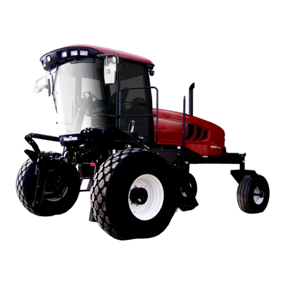
MacDon M105 Operator's Manual
Macdon m105 self-propelled windrower, tractor
Hide thumbs
Also See for M105:
- Operator's manual (384 pages) ,
- Assembly instructions manual (54 pages) ,
- Unloading and assembly instructions (53 pages)
Table of Contents
Advertisement
Quick Links
Advertisement
Table of Contents

Related Manuals for MacDon M105


Summary of Contents for MacDon M105
- Page 1 M105 Self-Propelled Windrower OPERATOR’S MANUAL MD #169552 Rev. C...
- Page 2 This Manual contains instructions for “SAFETY”, “OPERATION”, and “MAINTENANCE/SERVICE” for your new MacDon Model M105 Self-Propelled Windrower. CALIFORNIA Proposition 65 Warning Diesel engine exhaust and some of its constituents are known to the State of California to cause cancer, birth defects, and...
-
Page 3: Introduction
1 INTRODUCTION This manual contains information on the Model M105 Self-Propelled Windrower that is designed to cut and lay in windrows, a wide variety of grain, hay, and specialty crops. Windrowing allows starting the harvest earlier, protects the crop from wind damage, and gives you more flexibility in scheduling combine time. -
Page 4: Model And Serial Number
2 MODEL AND SERIAL NUMBER Record the model number, serial number, and model year of the windrower and engine on the lines below: WINDROWER SERIAL NO._________________YEAR______ Serial Number Plate is located on the left side of the main frame near the walking beam. ENGINE SERIAL NO._____________________YEAR_______ Serial Number Plate is located on top of the engine cylinder head cover. -
Page 5: Table Of Contents
TABLE OF CONTENTS Section/Title Page INTRODUCTION ............................ 1 MODEL AND SERIAL NUMBER ......................2 SAFETY ..............................7 SAFETY ALERT SYMBOL ......................7 SIGNAL WORDS ........................... 7 SAFETY SIGNS ..........................7 ... - Page 6 TABLE OF CONTENTS Section/Title Page 5.18 CAB DISPLAY MODULE (CDM) ....................38 5.18.1 Engine and Windrower Functions ......................38 5.18.2 Header Functions ........................... 38 5.18.3 Operating Screens ..........................39 5.18.4 Cab Display Module (CDM) Programming .....................
- Page 7 TABLE OF CONTENTS Section/Title Page MAINTENANCE SPECIFICATIONS ..................110 7.3.1 Recommended Torques ........................110 7.3.2 Recommended Fuel, Fluids And Lubricants ..................113 7.3.3 Conversion Chart ..........................114 MAINTENANCE REQUIREMENTS ..................115 ...
- Page 8 TABLE OF CONTENTS Section/Title Page 7.11.5 Traction Drive Hydraulics ........................176 7.11.6 Hoses and Lines ..........................177 7.11.7 Hydraulic Oil Cooler ..........................177 7.12 WHEELS AND TIRES ....................... 178 7.12.1 Drive Wheels ............................
-
Page 9: Safety
SAFETY 3 SAFETY WARNING 3.1 SAFETY ALERT SYMBOL Indicates a potentially hazardous situation that, if not avoided, could result in death or serious injury. It is also used to alert against unsafe practices. CAUTION Indicates a potentially hazardous situation that, if not avoided, may result in minor or moderate injury. - Page 10 SAFETY Safety Sign Locations (cont’d) A – LH Fan Shroud E – LH Cab Door MD# 166450 – top part of fan shroud MD# 166454 MD# 166451 – middle part of fan shroud F – LH Lift Linkage MD# 166452 – bottom part of fan shroud MD# 166438 B –...
- Page 11 SAFETY Safety Sign Locations (cont’d) 169552 / 169554 / 169555 Revision C...
- Page 12 SAFETY Safety Sign Locations (cont’d) A – RH Fan Shroud E – Radio Panel MD# 166451 – top MD# 166464 MD# 166452 – bottom F – Front Frame below Cab B – Hydraulic Oil Reservoir MD# 166425 MD# 174436 – center of tank G –...
- Page 13 SAFETY Safety Sign Locations (cont’d) 169552 / 169554 / 169555 Revision C...
-
Page 14: Safety Sign Interpretations
SAFETY 3.3.3 Safety Sign Interpretations In the safety sign explanations below, (a) refers to the top or left position panel, (b) refers to the bottom or right position of the safety decal depending on decal orientation. NOTE If there are more than two panels in a decal, the lettering will continue downward or to the right, depending on decal orientation. - Page 15 SAFETY 6. MD# 166450 a. Hot surface hazard. b. WARNING avoid injury, keep safe distance from hot surface. 4. MD# 166439 a. Crushing hazard. b. DANGER Rest header on ground or engage mechanical locks before going under unit. 7.
- Page 16 SAFETY 10. MD# 166455 9. MD# 166454 a. Explosion hazard. a. General hazard pertaining to machine b. WARNING operation and servicing. Prevent serious bodily injury caused b. CAUTION To avoid injury or death from improper Explosive battery gases. Keep or unsafe machine operation: sparks and flames away from the...
- Page 17 SAFETY vii. Keep all shields in place, and stay clear of moving parts. viii. Disengage header drive, transmission in neutral and wait for all movement to stop before leaving operator’s position. Shut off engine and remove key from ignition before servicing, adjusting, lubricating, cleaning, or unplugging machine.
- Page 18 If width of attached header impedes Do not go near leaks other vehicle traffic, remove header High pressure oil easily punctures skin and install a MacDon approved causing serious injury, gangrene, or weight box. Refer to operator’s death. manual for safe procedure to tow ...
- Page 19 SAFETY 17. MD# 184372 a. General hazard pertaining to machine operation and servicing. b. CAUTION To avoid injury or death from improper or unsafe machine operation: Read the operator’s manual, and follow all safety instructions. If you do not have a manual, obtain one from your dealer.
-
Page 20: General Safety
SAFETY 3.4 GENERAL SAFETY CAUTION following general farm safety precautions that should be part of your Provide a first-aid kit for use in case of operating procedure types machinery. emergencies. Keep a fire extinguisher on the machine. Protect yourself. Be sure the extinguisher is properly maintained, and be familiar with its ... - Page 21 SAFETY Do not modify the machine. Unauthorized modifications may impair the function and/or safety and affect machine life. Stop engine, and remove key from ignition before leaving Operator’s seat for any reason. A child or even a pet could engage an idling machine.
-
Page 22: Description
DESCRIPTION 4 DESCRIPTION 4.1 DEFINITIONS The following terms/abbreviations may be used in this manual: Term Definition American Petroleum Institute Articulating Power Tongue ASTM American Society Of Testing and Materials Windrower operation with the Operator and cab facing in the direction of Cab-Forward travel. -
Page 23: Specifications
SAFETY 4.2 SPECIFICATIONS ENGINE Type Cummins QSB - 4.5L 4 Cylinder Turbo Diesel. Bio-Diesel B20 Approved. Displacement 275 cu. in. (4.5 L) Rated 110 hp (81 kW) @ 2,500 rpm Power Peak 115 hp (86 kW) @ 2,300 rpm Bore 4-21/100 in (107 mm) Stroke 4-22/25 in. - Page 24 DESCRIPTION Pump (C): HEADER LIFT / TILT Hydraulic Double Acting Cylinders. Type Tilt - Optional Hydraulic Positioning, Optional Hydraulic Center-link Displacement 1.02 cu. in. (16.7 cc) Flow 11.5 gpm (44 L/min) Gear Pump System Pressure (Relief/Max) 2,500 psi (172 bar) Function Lift / Tilt / Float HEADER FLOTATION...
-
Page 25: Windrower Dimensions
SAFETY 4.3 WINDROWER DIMENSIONS See Illustration on Next Page. Wheel base Inch/mm Wheel Tread Hubs Casters Tires Shipping position Inch/mm Inch/mm Inch/mm Inch/mm Inch/mm Forward Reverse Drive tires Inner/Outer 123.1/3,127 139.1/3,532 142.2/3,612 18.4 x 26 Bar and Turf Outer/Outer 130.2/3,307 146.1/3,712 149.3/3,792 142.9/3,630... - Page 26 DESCRIPTION WINDROWER DIMENSIONS (cont’d) 133 in. (3,378 mm) 45.7 in. (1,160 mm) TREAD WHEEL BASE HUBS TIRES FORWARD TREAD WHEEL BASE CASTERS REVERSE 169552 / 169554 / 169555 Revision C...
-
Page 27: Component Identification
SAFETY 4.4 COMPONENT IDENTIFICATION MIRROR FIELD / ROAD LIGHTS HAND RAILS TURN SIGNAL/ DOOR HAZARD LIGHTS WINDSHIELD WIPER OPERATOR’S STATION HEADER FLOAT SPRINGS HEADER LIFT LEG CENTER-LINK MAINTENANCE PLATFORM TURN SIGNAL/ HORN FLOOD LIGHTS - REAR HAZARD LIGHTS ENGINE COMPARTMENT HOOD DOOR MIRROR RED TAIL LIGHTS... -
Page 28: Operator's Station
OPERATOR’S STATION 5.2 SEAT ADJUSTMENTS 5 OPERATOR’S STATION The Operator’s seat has several adjustments. Refer to the illustration below for the location The Operator’s station is designed for operating and description of each adjustment. the windrower in a cab-forward mode. 5.1 OPERATOR CONSOLE LUMBAR SUPPORT Adjusts Stiffness of Seat Back... -
Page 29: Training Seat (Optional)
OPERATOR’S STATION 5.3 TRAINING SEAT (OPTIONAL) A wall mounted fold-up training seat complete with seat belt is provided for use as described below. SEAT BELT RELEASE a. To fasten seat belt, pull belt completely across your body. Push the metal eye into the buckle until it locks. -
Page 30: Operator Presence
OPERATOR’S STATION 5.6 OPERATOR PRESENCE The Operator Presence System is a safety feature that is designed to deactivate or alarm selected systems when the Operator is not seated at the Operator’s station. These systems include: Header Drive. Transmission. ... -
Page 31: Lights
OPERATOR’S STATION 5.7.1 Field Lighting 5.7 LIGHTS The field and transport light switches are located on a panel in the cab headliner. For location of lights, refer to illustrations below: LIGHTS SWITCH Controls Field and Transport Lights FIELD ROAD FIELD LIGHTS BEACON Controls Beacons On Cab Standard for Export. -
Page 32: Road Lighting
OPERATOR’S STATION 5.7.2 Road Lighting 5.7.3 Beacon Lighting: Export (N.A. Optional) The following lights are ON/functional when the switch is in the ROAD position. The beacon lights are functional when the ignition and the beacon switches are ON. The hazard lights must be activated with the The beacons must be used when driving on the switch on the Cab Display Module (CDM) when driving on the road. -
Page 33: Windshield Wiper
OPERATOR’S STATION 5.8 WINDSHIELD WIPER 5.9 REAR VIEW MIRRORS WIPER SWITCH REAR VIEW MIRRORS Controls Windshield Wiper ON / OFF The windshield wiper control is located in the cab headliner. Two adjustable outside mounted mirrors provide rear view vision. The mirror/light assembly is designed to fold backwards if accidentally struck either during normal operation, or by another machine. -
Page 34: Cab Temperature
OPERATOR’S STATION 5.10.2 Air Distribution 5.10 CAB TEMPERATURE The cab environment is controlled by a climate-control system that provides clean air-conditioned or heated air for the Operator. OPEN heater/evaporator/blower assembly CLOSE located under the cab floorboard, and is accessible from beneath the windrower. 5.10.1 Controls DIRECTION Refer to the following illustrations for an... -
Page 35: A/C Compressor Protection
OPERATOR’S STATION 5.10.4 A/C Compressor Protection 5.12 OPERATOR AMENITIES The compressor is protected from excessively low and high pressures by two switches that shut down the compressor to prevent damage to the system. The LOW pressure switch opens when the CIGARETTE LIGHTER pressure falls to 2–8 psi (14–55 kPa), and... -
Page 36: Radios
IMPORTANT pre-wired speakers have been Antenna base can only be installed on the factory-installed in the headliner. Refer to M105 LH and RH rear cab roof bolts. Self-Propelled Windrower Unloading Assembly Instruction (MD# 169558) for radio 5.14 HORN installation procedures. -
Page 37: Engine Controls
OPERATOR’S STATION 5.15 ENGINE CONTROLS IGNITION SWITCH ACC - Fully Counter Clockwise OFF - All Electrical Systems OFF RUN - Clockwise START- Fully Clockwise To Crank Engine. Release and Switch Returns to RUN. REMOVE KEY WHEN WINDROWER NOT IN USE. KEY ALSO LOCKS DOORS. -
Page 38: Header Controls
OPERATOR’S STATION 5.17.3 Ground Speed Lever (GSL) Header 5.17 HEADER CONTROLS Switches All header controls are conveniently located on the Operator’s console, and on the Ground Speed Lever (GSL) handle. NOTE Some controls are optional equipment, and may not be present in your unit. Some controls may be installed, but will be non-functional for certain headers. - Page 39 OPERATOR’S STATION 5.17.3.1 Display Selector Switch 5.17.3.3 Header Position Switches DISPLAY DISPLAY HEADER UP HEADER TILT DOWN HEADER HEADER DOWN TILT UP DISPLAY SELECTOR Selects and displays the settings in the Cab Press and hold the switch at location shown Display Module (CDM) display top line read-out to move header.
-
Page 40: Cab Display Module (Cdm)
OPERATOR’S STATION 5.18 CAB DISPLAY MODULE (CDM) 5.18.1 Engine and Windrower Functions HAZARD WARNING LIGHTS SWITCH DISPLAY GROUND SPEED Activates Hazard Warning Lights. mph or kph Engine / Windrower Functions Cancels Turn Signal. ENGINE RPM SELECT SWITCH ENGINE WARNING LIGHTS Allows Operator To Select Display Engine Pre-Heat / Water In Fuel / Item On Lower Line. -
Page 41: Operating Screens
SELECTOR DISPLAY SELECTOR The M105 windrower Cab Display Module (CDM) and the Windrower Control Module (WCM) provide information on several functions for the engine, header, and windrower. The information displayed in various operating modes is described in the following sections: IGNITION ON / ENGINE NOT RUNNING Display (upper line) (2–3 seconds) - Page 42 OPERATOR’S STATION ENGINE RUNNING / HEADER DISENGAGED (Scroll Through Display with Cab Display Module [CDM] Switch or Ground Speed Lever [GSL] Switch) Display (lower or upper line) Description #####.# ENGINE HRS Total Engine Operating Time. #####.# UNIT HRS Total Windrower Operating Time. #####.# HEADER HRS Total Header Operating Time.
- Page 43 OPERATOR’S STATION ENGINE RUNNING / HEADER ENGAGED AUGER HEADER (Scroll Through Display with Cab Display Module [CDM] Switch or Ground Speed Lever [GSL] Switch) Display (lower or upper line) Description #####.# ENGINE HRS Total Engine Operating Time. #####.# UNIT HRS Total Windrower Operating Time.
- Page 44 OPERATOR’S STATION ENGINE RUNNING / HEADER ENGAGED DRAPER HEADER / INDEX SWITCH OFF (Scroll Through Display with Cab Display Module [CDM] Switch or Ground Speed Lever [GSL] Switch) Display (lower or upper line) Description #####.# ENGINE HRS Total Engine Operating Time. #####.# UNIT HRS Total Windrower Operating Time.
- Page 45 OPERATOR’S STATION ENGINE RUNNING / HEADER ENGAGED DRAPER HEADER / INDEX SWITCH ON (Scroll Through Display with Cab Display Module [CDM] Switch or Ground Speed Lever [GSL] Switch) Display (lower or upper line) Description #####.# ENGINE HRS Total Engine Operating Time. #####.# UNIT HRS Total Windrower Operating Time.
- Page 46 OPERATOR’S STATION CAB DISPLAY MODULE (CDM) WARNINGS/ALARMS The CDM displays warnings and sounds alarms to notify the Operator of abnormal windrower status at startup when the ignition is turned ON, and at engine operating speeds above 500 rpm. 5.18.3.1 Engine Warning Lights CAUTION ENGINE PREHEAT Illuminates Yellow...
- Page 47 OPERATOR’S STATION 5.18.3.2 Display Warnings DISPLAY WARNINGS Informs Operator of Abnormal Windrower Conditions See Table Below DISPLAY WARNINGS AND ALARMS - ENGINE/TRANSMISSION Display Alarm tone Description Continuous Loud Tone Until Oil Low Engine Oil Pressure. ENGINE OIL PRESSURE Pressure Is Regained. Accompanied By Warning Lights.
- Page 48 OPERATOR’S STATION DISPLAY WARNINGS AND ALARMS - WINDROWER Display Alarm tone Description Interlock Switch Not Closed With Key ON / Engine OFF. GSL not in CENTER STEERING Beeps At 2 Per Second N-DETENT or steering wheel not centered. Header Switch Is ON When Ignition ...
-
Page 49: Cab Display Module (Cdm) Programming
Most functions have been pre- programmed at the factory, but can be changed NOTE by the Operator if required. Contact your MacDon Dealer information regarding software updates to Proceed as follows to program the CDM: the electronic modules. IMPORTANT... - Page 50 OPERATOR’S STATION DETAILED PROGRAMMING INSTRUCTIONS (Key On / Engine Running or Not / Header Disengaged). (Press PROGRAM and SELECT on Cab Display Module [CDM] to enter Programming Mode). NOTE: ENGINE MUST BE RUNNING TO CALIBRATE SENSORS. Programming Menu Flow Chart for Software version C107 and M102 (or higher) L1 C x x x || W I N D R O W E R S E T U P ? If "NO"...
- Page 51 OPERATOR’S STATION C x x x || S E T C O N T R O L L O C K S ? If “NO” then jump to: M x x x || N O / Y E S V I E W C O N T R O L L O C K S ? C x x x || D R A P E R...
- Page 52 OPERATOR’S STATION C x x x || D I S P L A Y U N I T S ? The “arrow” keys are used to select between M x x x || I M P E R I A L IMPERIAL or METRIC.
- Page 53 OPERATOR’S STATION L1 C x x x || D I A G N O S T I C M O D E ? If “NO” then jump to: L2 M x x x || N O / Y E S W I N D R O W E R S E T U P ? C x x x || V I E W...
- Page 54 OPERATOR’S STATION C x x x || A C T I V A T E F U N C T I O N S ? If “NO” then jump to: M x x x || N O / Y E S E X I T D I A G N O S T I C ? C x x x || A C T I V A T E...
-
Page 55: Engine Error Codes
OPERATOR’S STATION 5.18.5 Engine Error Codes The Cab Display Module (CDM) displays Error Codes when there is a fault with one of the several sensors that monitor and control engine operation, to assist the Operator or Technician in locating a specific problem with engine operation. -
Page 56: Operation
WINDROWER OPERATION 6.2 SYMBOL DEFINITIONS 6 OPERATION The following symbols are used to depict functions or reactions at the various instruments 6.1 OWNER/OPERATOR and controls. RESPONSIBILITIES Learn the meaning of these symbols before operating the windrower. CAUTION 6.2.1 Engine Functions ... -
Page 57: Windrower Operating Symbols
WINDROWER OPERATION 6.2.2 Windrower Operating Symbols 6.2.3 Header Functions Windshield Header Tilt Turn Signals Program Wiper Hazard Seat Height Header Header Index Warning Lights Down Seat Height Forward Return To Cut Header Up Down Seat Fore Conveyor/Auger Header Tilt Neutral and Aft Speed Down... -
Page 58: Windrower Operation
WINDROWER OPERATION Check excessive vibration 6.3 WINDROWER OPERATION unusual noises. If there is any indication of trouble, shut down and inspect the 6.3.1 Operational Safety machine. Follow proper shutdown procedure. Section 6.3.4.3 Follow these safety precautions: Shutdown. CAUTION Operate only in daylight or good artificial light. -
Page 59: Daily Check
WINDROWER OPERATION 6.3.3 Daily Check a. Check the machine for leaks or any parts that are missing, broken, or not working correctly. NOTE: Use proper procedure when searching for pressurized fluid leaks. See Section 7.11.6 Hoses and Lines. b. Clean the windows and mirrors to be sure of good visibility in all directions. -
Page 60: Engine Operation
WINDROWER OPERATION 6.3.4 Engine Operation 6.3.4.1 Starting DANGER Avoid possible injury or death from a runaway machine. This machine has safety devices which allow the engine to start only when the Ground Speed Lever (GSL) N-DETENT, the steering wheel is locked in the NEUTRAL position, and the header drive switch... - Page 61 WINDROWER OPERATION Sound horn (E) three times. CAUTION When grid heater light goes out, turn key to START, and crank engine until it starts. Leave throttle at Be sure the area is clear of other persons, IDLE. pets etc. before proceeding. If engine fails to start, repeat steps 2 to 5.
- Page 62 WINDROWER OPERATION 6.3.4.4 Fueling 6.3.4.2 Engine Intermediate Speed Control (ISC) WARNING This is useful when operating loads are reduced such as in light crop conditions that do not require the maximum engine rpm. Reduced engine speed lowers fuel consumption, noise levels, and exhaust emissions, in addition to reducing engine wear.
- Page 63 WINDROWER OPERATION 6.3.4.5 Engine Temperature 6.3.4.7 Electrical The normal engine operating temperature range Indicated Ignition Engine Reading is 180°–225°F (82°–107°C). condition 13.8–15.0 Normal. ENGINE TEMP XXX°F > 16.0 Regulator Out of Adjustment. See Note. Running Alternator Not < 12.5 Working or Regulator Out of See Note.
-
Page 64: Driving The Windrower
WINDROWER OPERATION 6.3.5 Driving The Windrower CAUTION WARNING With the engine running, moving the Ground Speed Lever (GSL) Before starting engine, securely fasten your N-DETENT unlocks steering. seat belt, and ensure Trainer’s seat belt is movement of steering wheel will then fastened (if occupied). - Page 65 WINDROWER OPERATION Avoid inclines, ditches and fences. Do not rapidly accelerate or decelerate when turning. Reduce speed before turning, crossing slopes, or travelling over rough ground. Do not allow anyone to stand behind the machine while operating. Foreign objects may be forcibly ejected.
- Page 66 WINDROWER OPERATION 6.3.5.2 Operation 6.3.5.2.1 Reverse WARNING Back up slowly. Steering is opposite to normal when reversing. Hold steering wheel at the bottom, and turn wheel in direction you want the rear of the machine to travel. a. Place Ground Speed Lever (GSL) (A) in N-DETENT.
- Page 67 WINDROWER OPERATION 6.3.5.3 Spin Turn 6.3.5.4 Stopping Hydrostatic steering gives Operator WARNING significantly more manoeuvrability than mechanical steering. Do not move ground speed lever rapidly back to NEUTRAL. Operator may be thrown CAUTION forward by sudden stop. Always wear seat belt when operating windrower.
-
Page 68: Adjustable Caster Tread Width
WINDROWER OPERATION 6.3.6 Adjustable Caster Tread Width The rear casters can be adjusted to a narrow tread width to allow loading and shipping without having to remove them. A narrow tread width also suits smaller headers by allowing more space to the uncut crop, and provides more maneuverability around poles, irrigation inlets, or other obstacles. - Page 69 WINDROWER OPERATION d. Position bracket (A), and install bolts (B). The two shorter bolts are installed at the back inboard locations. e. Install bottom bolts (C). Tighten bolts as follows: 1. Snug bottom bolts (C). 2. Tighten and torque back bolts (B) to 330 lb-ft (447 N·m).
-
Page 70: Transporting
If width of attached header impedes other and head lamps, and check that they work vehicle traffic, remove header, and install properly. a MacDon approved weight box. 2. Clean all reflective surfaces and Slow Moving Vehicle (SMV) emblems. CAUTION 3. Adjust interior rear view mirror, and clean windows. - Page 71 With header removed, steering control is reduced if weight is not added to drive wheels. If you must drive the windrower without header or MacDon weight system: Operate in low speed range. Do not exceed 1,500 rpm engine speed.
- Page 72 The windrower can be used to tow a MacDon Harvest Header with the Slow Speed Transport option installed, provided the Weight Box option...
- Page 73 WINDROWER OPERATION 6.3.7.2.1 From Field to Transport Mode a. Set header on the ground. DANGER Stop engine, and remove key from ignition before leaving Operator’s seat for any reason. A child or even a pet could engage an idling machine. b.
- Page 74 WINDROWER OPERATION 2. Release safety lock on the header lift 1. Drive windrower so that windrower lift arms cylinders. are located in the weight box pockets. 3. Lower header down onto the transport 2. Raise lift arms slightly. wheels. 3. Stop engine, and remove key. 4.
- Page 75 WINDROWER OPERATION 3. If the tow-bar (A) is too far from the drawbar m. Attach tow-bar to windrower. (B): M105 transport drawbar provides i. Remove pin (C), lift the drawbar support approximately 12 in. (300 mm) of fore-aft (D) until the tow-bar clevis aligns, and movement to ease the attachment of a towed then install the drawbar pin (E).
- Page 76 WINDROWER OPERATION Before moving the machine: double check that all pins are secure, the drawbar and hitching components are not showing signs of damage, and that all safety equipment is installed and fully functional. n. Connect safety chain (G) through the slot (H) in drawbar support, and securely attach the hook (J) to the chain.
- Page 77 WINDROWER OPERATION 6.3.7.2.2 From Transport Mode To Field Operation DANGER Stop engine, and remove key from ignition before leaving Operator’s seat for any reason. A child or even a pet could engage an idling machine. a. Shut down windrower, and remove key. d.
- Page 78 WINDROWER OPERATION m. Start engine, and lower header to ground. Continue to retract lift cylinders so that member IMPORTANT (N) lifts off link (O). To prevent damage to the lift system when n. Remove temporary lift pins (P) from lift arms, lowering header lift linkages without a and install pins into storage holes in weight box.
-
Page 79: Towing The Windrower
WINDROWER OPERATION 6.3.8 Towing the Windrower IMPORTANT Failure to disengage final drives before In emergency situations (for example, towing out towing will result in serious transmission of a field or into a shop), windrower may be damage. towed without a trailer, providing the following precautions are followed: IMPORTANT Do not exceed 16 mph (26 km/h) when... -
Page 80: Storage
Check for broken components, and order 6.3.9 Storage replacements from your MacDon Dealer. At the end of each operating season: Attention to these items right away will save time and effort at beginning of next season. a. Clean the windrower thoroughly. -
Page 81: Header Operation
HEADER OPERATION - GENERAL 6.4 HEADER OPERATION The M105 Windrower is designed to use the MacDon A-Series Auger Header, and 65 Series Rigid Draper Headers (up to 35 FT) with or without a Hay Conditioner. This section describes the attachment and... -
Page 82: Header Flotation
HEADER OPERATION - GENERAL 6.4.2 Header Flotation 6.4.2.2 Float Adjustment Float is intended for cutting crops that require The float adjustment uses drawbolts to change the cutterbar to be in contact with the ground. the tension on the springs in the lift linkages. Optimum float is for the cutterbar to maintain a. - Page 83 HEADER OPERATION - GENERAL Force to lift cutterbar at ends with lift Header cylinder fully retracted Auger 75–85 lbf (335–380 N) 75–85 lbf (335–380 N) with Draper Stabilizer/Transport Wheels raised (if equipped). b. If necessary, adjust the float with the drawbolts as follows: CAUTION 3.
-
Page 84: Levelling
HEADER OPERATION - GENERAL 4. Place wooden blocks under header 6.4.3 Levelling cutterbar and legs. The windrower linkages are factory-set to provide the proper level for the header, and should not normally require adjustment. If the header is not level, perform the following checks prior to adjusting the leveling linkages. -
Page 85: Header Drive
This feature IMPORTANT requires that an optional module has been Always move throttle lever back to idle installed, either at the factory or at your MacDon before engaging header drive. Do not Dealer. engage header with engine at full rpm. - Page 86 HEADER OPERATION - GENERAL Change header angle as follows: d. Periodically check the operation of the hook locking mechanism, and ensure that it is working HYDRAULIC CENTER-LINK (OPTIONAL) properly as follows: DISPLAY HEADER TILT DOWN 1. If header attached windrower, HEADER TILT UP disconnect center-link hook from header by...
-
Page 87: Cutting Height
HEADER OPERATION - GENERAL 6.4.6.1 Return To Cut (Optional) The monitoring system assists the Operator in maintaining the desired cutting height with the optional RETURN TO CUT feature that can be turned OFF or ON with a switch on the Cab Display Module (CDM). -
Page 88: Swath Roller Operation
HEADER OPERATION - GENERAL b. Use the RETURN TO CUT feature as follows: 3. Press SELECT. TRACTOR SETUP? is displayed on upper line. IMPORTANT 4. Press , then SELECT. SET KNIFE Ensure the header is engaged, and the SPEED? is displayed. RETURN TO CUT switch is illuminated. -
Page 89: D Series Header Operation
RH side. 6.5.1 Configure Hydraulics If necessary, obtain Kit B5577 from your The M105 windrower must be fitted with a MacDon Dealer, and install it in accordance with draper drive basic... -
Page 90: Header Attachment
HEADER OPERATION - D SERIES IMPORTANT For machines equipped with the hydraulic center-link, it may contact the header as the windrower approaches the header for hook-up. b. Locate boot (D) on lift linkage (E), and re-install pin (C). Pin may be installed from either side of b. - Page 91 HEADER OPERATION - D SERIES MECHANICAL LINK Connect center-link: HYDRAULIC LINK WARNING Stop windrower engine, and remove key before making adjustments to machine. A HEADER UP child or even a pet could engage the drive. 1. Stop engine, and remove key from ignition. HEADER HEADER TILT UP TILT DOWN...
- Page 92 HEADER OPERATION - D SERIES DANGER To avoid bodily injury from fall of raised header, always engage header lift cylinder stops when working on or around raised header, and before going under header for any reason. Disengage lift cylinder stop by turning lever (T) h.
-
Page 93: Header Position
HEADER OPERATION - D SERIES 6.5.4 Header Position See Section 6.4 HEADER OPERATION for procedures for controlling header height, header tilt, and float. 6.5.5 Reel Fore-Aft Position REEL FORWARD REEL AFT Press and hold the switch for the desired fore or aft movement of the reel. -
Page 94: Reel Speed
Ground Speed Plus Index your MacDon Dealer. is less than the Minimum Reel Speed Set To use this feature, set the Minimum Reel Point. - Page 95 HEADER OPERATION - D SERIES Example: Windrower is operating at 8 mph with HEADER INDEX ON, and set at -1.0. Display shows: 7.0 -1.0 REEL IND where 7.0 (8.0 - 1.0) is the reel speed in mph, and -1.0 is the HEADER INDEX setting.
-
Page 96: Draper Speed
HEADER OPERATION - D SERIES a. Set Draper Minimum Speed: 6.5.8 Draper Speed IMPORTANT Draper speed affects the orientation of stalks in Windrower can be moving but must be the windrow. Faster draper speeds tend to form less than minimum reel speed. herringbone or dovetail configurations. - Page 97 HEADER OPERATION - D SERIES 6.5.8.2 Draper Speed Independent of Ground Example: Speed Windrower is operating at 8 mph with Set the speed of the draper independently of HEADER INDEX ON, and set at 1.5. ground speed as follows: Display shows: NOTE 9.5 1.5 DRAP INDX...
-
Page 98: Knife Speed
HEADER OPERATION - D SERIES e. Run engine at maximum rpm. 6.5.9 Knife Speed DISPLAY The ideal cutting speed of the knife should be such that a clean cut is achieved. Crop types and conditions usually influence the knife and forward speeds. -
Page 99: Deck Shift (Optional)
HEADER OPERATION - D SERIES NOTE 6.5.10 Deck Shift (Optional) One turn of the adjuster screw (B) will The hydraulic deck shift option allows the change the knife speed by approximately Operator to control deck position and draper 116 Strokes Per Minute, or the sickle drive rotation from the Operator’s station. -
Page 100: Header Detachment
HEADER OPERATION - D SERIES 6.5.11 Header Detachment HEADER UP HEADER HEADER TILT UP TILT DOWN HEADER DOWN e. Remove pin from location (D) to disengage float springs, and insert in storage hole (E). Secure with lynch pin. a. Raise header fully with the HEADER UP switch on the Ground Speed Lever (GSL). - Page 101 HEADER OPERATION - D SERIES MECHANICAL LINK Disconnect header drive hydraulics (F) and 1. Loosen nut (L), and rotate barrel (M), to electrical harness (G) from header. Refer to the relieve load on link. draper header operator’s manual. 2. Remove cotter pin on pin (N), and remove pin to disconnect from windrower.
-
Page 102: A Series Header Operation
HEADER OPERATION - A SERIES IMPORTANT 6.6 A SERIES HEADER OPERATION For machines equipped with the hydraulic center-link, it may contact the header as the windrower approaches the header for hook-up. 6.6.1 Header Attachment b. If necessary, re-locate the pin (E) at the frame linkage as required to raise the center-link (F) so that the hook (G) is above the attachment pin on the header. - Page 103 HEADER OPERATION - A SERIES IMPORTANT Hook release must be down to enable self-locking mechanism. If the release is up, manually push it down after hook engages header pin. 4. Check that center-link is locked onto header by pulling upward on rod end of cylinder. 5.
- Page 104 HEADER OPERATION - A SERIES DANGER To avoid bodily injury from fall of raised header, always engage header lift cylinder stops when working on or around raised header, and before going under the header for any reason. h. Engage lift cylinder stops on both lift cylinders. See Section 6.4.1 Header Lift Cylinder Stops.
-
Page 105: Auger Speed
HEADER OPERATION - A SERIES 6.6.2 Auger Speed 6.6.2.2 A30-S and A30-D Headers On A30 Series auger headers, the auger speed CAUTION is fixed to the knife speed. NOTE Check to be sure all bystanders have cleared The auger speed can be independently the area. -
Page 106: Reel Speed
HEADER OPERATION - A SERIES 6.6.3 Reel Speed ENGAGE HEADER 6.6.3.1 A30-S and A30-D Headers The reel speed is fixed to the auger speed and HEADER INDEX to the knife speed. Both can be changed by SWITCH - OFF installing alternate drive sprockets. Refer to your auger header operator’s manual. -
Page 107: Knife Speed
HEADER OPERATION - A SERIES 6.6.4 Knife Speed e. Run engine at maximum rpm. Press SELECTOR button on the Ground Speed The ideal cutting speed of the knife should be such that a clean cut is achieved. Crop types DISPLAY and conditions usually influence the knife and forward speeds. - Page 108 HEADER OPERATION - A SERIES NOTE One turn of the adjuster screw (B) will change the knife speed by approximately 116 Strokes Per Minute, or the sickle drive box pulley speed by 58 Revolutions Per Minute. 4. Once adjustment has been made, re-torque jam nut (A) as shown on previous page.
-
Page 109: Header Detachment
HEADER OPERATION - A SERIES 6.6.5 Header Detachment HEADER UP HEADER HEADER TILT UP TILT DOWN HEADER DOWN d. Lower stand (C) by pulling pin (D), inverting a. Raise the header fully with the HEADER UP stand, and re-locating on bracket. Re-insert pin switch on the Ground Speed Lever (GSL). - Page 110 HEADER OPERATION - A SERIES MECHANICAL LINK h. Disconnect center-link: HYDRAULIC LINK (OPTIONAL) 1. Stop engine and remove key from ignition. REEL DOWN REEL UP HEADER HEADER TILT UP TILT DOWN 2. Loosen nut (G), and rotate barrel (H) to relieve load on link.
-
Page 111: Maintenance And Servicing
MAINTENANCE AND SERVICING 7 MAINTENANCE AND SERVICING The following instructions are provided to assist the Operator in the use of the M105 Windrower. Detailed maintenance, service, parts information are contained in the technical Wear protective shoes with slip-resistant manual and parts catalog that are available from soles, a hard hat, protective glasses or your MacDon Dealer. -
Page 112: Maintenance Specifications
MAINTENANCE AND SERVICING 7.3.1.2 Metric Bolts 7.3 MAINTENANCE SPECIFICATIONS Std coarse bolt torque* 7.3.1 Recommended Torques Bolt dia. 10.9 “A” The tables shown below give correct torque lb-ft N·m lb-ft N·m values for various bolts and cap screws. Tighten all bolts to the torques specified in chart (unless otherwise noted throughout this manual). - Page 113 MAINTENANCE AND SERVICING 7.3.1.3 Flare Type Hydraulic Fittings 7.3.1.4 O-Ring Boss (ORB) Hydraulic Fittings FITTING LOCKNUT FLARE WASHER O-RING GROOVE SEAT BODY FLARESEAT a. Check flare and flare seat for defects that might cause leakage. b. Align tube with fitting before tightening. a.
- Page 114 MAINTENANCE AND SERVICING a. Check components to ensure that the sealing 7.3.1.5 O-Ring Face Seal (ORFS) Hydraulic surfaces and fitting threads are free of burrs, Fittings nicks, and scratches, or any foreign material. b. Apply lubricant (typically Petroleum Jelly) to O-ring and threads.
-
Page 115: Recommended Fuel, Fluids And Lubricants
MAINTENANCE AND SERVICING 7.3.2.3 Lubricants 7.3.2 Recommended Fuel, Fluids And Lubricants Lubricant Spec / description 7.3.2.1 Fuel SAE Multi-Purpose. As Required High Temperature Extreme Use good quality diesel fuel in your vehicle from Unless Pressure (EP2) Performance Grease Otherwise With 1% Max Molybdenum a reputable supplier. -
Page 116: Conversion Chart
MAINTENANCE AND SERVICING 7.3.3 Conversion Chart Inch-pound units Si units (metric) Quantity Factor Unit name Abbr. Unit name Abbr. Area acres acres x 0.4047 = hectares gallons per minute (US) gpm (US) x 3.7854 = Flow liters per minute L/min gallons per minute (Imp) x 4.5460 = Force... -
Page 117: Maintenance Requirements
MAINTENANCE AND SERVICING 7.4 MAINTENANCE REQUIREMENTS Periodic maintenance requirements organized by service intervals. Regular maintenance is the best insurance against early wear and untimely breakdowns. Following this schedule will increase machine life. For detailed instructions, refer to the specific headings in this section. Use the fluids and lubricants specified Section... -
Page 118: Maintenance Schedule / Record
MAINTENANCE AND SERVICING 7.4.1 Maintenance Schedule / Record M105 Windrower Serial Number: _______________________ Combine this page with the record in the Header Operator’s Manual. Copy this page to continue the record. ACTION: - Change - Check - Lubricate ... - Page 119 MAINTENANCE AND SERVICING ACTION: - Check - Lubricate - Change - Clean + - Add Hour Meter Reading Date Serviced By 250 HOURS OR ANNUALLY * Engine Air Filter Primary Element ** 7.8.5 Engine Oil and Filter 7.8.4 ...
-
Page 120: Break-In Inspections
MAINTENANCE AND SERVICING 7.4.2 Break-In Inspections ITEM SEE SECTION Every 1/4 Hour Road Check Drive Wheel Nut Torque - 220 lb·ft (300 N·m). 7.12.1.2 Repeat Checks Until Torque Stabilizes. 1 Hour Field Check A/C Belt Tension. 7.8.10.1 Check Caster Wheel Nut Torque - 120 lb·ft (163 N·m). 7.12.2.3 Check Caster Wheel Anti-Shimmy Dampener Bolt Torque. -
Page 121: Pre-Season/Annual Service
MAINTENANCE AND SERVICING 7.4.3 Pre-Season/Annual Service 6. Cycle A/C switch to distribute A/C refrigerant oil as follows: a. Perform the following at the beginning of each operating season: IMPORTANT Perform the following steps whenever the CAUTION machine is first started after storage for more than one week: ... -
Page 122: End Of Season Service
Fuel, Fluids and Lubricants. Check for broken components and order replacements from your MacDon Dealer. b. Wipe grease fitting with a clean cloth before Attention to these items right away will save time greasing, to avoid injecting dirt and grit. -
Page 123: Every 50 Hours
MAINTENANCE AND SERVICING EVERY 50 HOURS High Temperature Extreme Pressure (EP2) Performance With 1% Max Molybdenum Disulphide (NLGI Grade 2). Lithium Base. TOP LINK - TWO FITTINGS (BOTH SIDES) WALKING BEAM PIVOT FORKED CASTER SPINDLE BEARINGS TWO PLACES (BOTH WHEELS) CASTER PIVOT (BOTH SIDES) 169552 / 169554 / 169555... - Page 124 MAINTENANCE AND SERVICING EVERY 250 HOURS High Temperature Extreme Pressure (EP2) Performance With 1% Max Molybdenum Disulphide (NLGI Grade 2).Lithium Base. FORMED CASTER WHEEL BEARING 1 PLACE (BOTH WHEELS) 169552 / 169554 / 169555 Revision C...
-
Page 125: Engine Compartment Hood
MAINTENANCE AND SERVICING c. Open the hood at the highest position as 7.5 ENGINE COMPARTMENT HOOD follows: The engine hood has two open positions: 1. Open hood to lowest position. The lowest is for general maintenance such as checking and adding fluid, servicing the cooling box, etc. -
Page 126: Maintenance Platform
MAINTENANCE AND SERVICING 7.6.2 Opening/Closing Platform for Major 7.6 MAINTENANCE PLATFORM Servicing A swing away platform/stair is provided for To improve access to the hydraulics plumbing, access to the Operator’s station and engine bay the platform can be swung away from the maintenance. - Page 127 MAINTENANCE AND SERVICING CAUTION Do not stand on the platform in the unlocked position. It is unstable and may result in a fall. e. Close platform as follows: 1. Swing link (D) all the way forward. 2. Move platform front end inboard while moving it away from the walking beam.
-
Page 128: Operator's Station
MAINTENANCE AND SERVICING d. With the windrower moving at more than 5 mph 7.7 OPERATOR’S STATION (8 km/h): 1. Stand up out of the seat. 7.7.1 Seat Belts 2. The CDM beeps once and displays “NO a. Keep sharp edges and items that can cause OPERATOR”... -
Page 129: Ground Speed Lever (Gsl) Adjustments
MAINTENANCE AND SERVICING The Neutral Start Switch should also be fully 7.7.3 Ground Speed Lever (GSL) compressed. If the cable is too tight, it will Adjustments prevent the Neutral Start Switch from fully compressing, and prevent proper engagement 7.7.3.1 Ground Speed Lever (GSL) Lateral of pintle arm. - Page 130 MAINTENANCE AND SERVICING 7.7.3.3 Ground Speed Lever (GSL) Position The GSL should be centered fore-aft (A) in the N-DETENT slot when the steering wheel is centered and locked. If necessary, adjust as follows: IMPORTANT Neutral Interlock must properly adjusted before adjusting GSL position. a.
-
Page 131: Steering Adjustments
MAINTENANCE AND SERVICING 7.7.4 Steering Adjustments If steering rod bolts (A) are loose: 7.7.4.1 Steering Link Pivots Perform the following checks annually: DANGER Stop engine, and remove key from ignition before leaving Operator’s seat for any reason. A child or even a pet could engage an idling machine. -
Page 132: Neutral Start Switch
MAINTENANCE AND SERVICING g. If steering link bolts (E) are loose: 7.7.5 Neutral Start Switch The Neutral Start Switch (A) must be closed before the engine can be started. The switch is closed when the Neutral Interlock on the pump is activated by positioning the Ground Speed Lever (GSL) into N-DETENT, and locking the steering wheel in CENTER position. -
Page 133: Hvac System
MAINTENANCE AND SERVICING 7.7.6 HVAC System c. Direct compressed air (100 psi [700 kPa] maximum) through filter in opposite direction of 7.7.6.1 Fresh Air Intake Filter air flow arrows. d. Wash filter as required: The fresh air filter is located under the cab roof 1. - Page 134 MAINTENANCE AND SERVICING 7.7.6.2 Return Air Filter 7.7.6.3 A/C Condenser The return air filter is located behind the The air conditioning condenser should be Operator’s seat on the cab wall, and should be cleaned daily with compressed air, and more serviced every 100 hours as follows: frequent cleaning may be necessary in severe conditions.
- Page 135 See Section 7.8.10.2 A/C Compressor Belt WARNING Replacement for belt replacement procedures. b. See your MacDon Dealer or your technical To avoid cuts from evaporator fins, do not manual for all other servicing procedures. use bare hands to brush away clogs.
-
Page 136: Engine
General Engine Inspection cable clamps. Loosen clamps, and remove cable from batteries. Engine inspection should be performed by your MacDon Dealer. Refer to your engine manual for further information. (Owner’s Manual QSB4.5 and QSB6.7 Engine Cummins # 4021531 supplied with your machine). -
Page 137: Oil Level
MAINTENANCE AND SERVICING g. Add oil as follows if level is below the LOW 7.8.3 Oil Level mark: 2 U.S. quarts (1.9 liters) will raise the level Check engine oil level frequently, and watch for from LOW to HIGH. any signs of leakage. CAUTION NOTE During the break-in period, a higher than... -
Page 138: Changing Oil And Oil Filter
MAINTENANCE AND SERVICING Screw the new filter onto the filter mount until 7.8.4 Changing Oil and Oil Filter the gasket contacts the filter head. NOTE k. Tighten the filter an additional 1/2 to 3/4 turn by The engine should be warm prior to hand. -
Page 139: Air Intake System
MAINTENANCE AND SERVICING 7.8.5.1 Air Filter Servicing 7.8.5 Air Intake System IMPORTANT DANGER Do not run engine with air cleaner disconnected or disassembled. Stop engine, and remove key from ignition before leaving Operator’s seat for any reason. A child or even a pet could engage an idling machine. - Page 140 MAINTENANCE AND SERVICING d. If service indicator was red, service filters. IMPORTANT e. Slightly lift catch (G) at side of end cap (F), and Leave safety element (L) in place to rotate end cap counter clockwise until it stops, prevent ingress of dirt into engine intake. and arrow (H) lines-up with UNLOCK symbol on end cap.
- Page 141 MAINTENANCE AND SERVICING p. Inspect the air intake piping for damage, cracked 7.8.5.2 Filter Element Cleaning hoses, loose clamps, etc. Repair or replace damaged parts, and tighten loose clamps. IMPORTANT element filter cleaning recommended possible degradation of the element material. If cleaning is performed, there are several risks involved,...
-
Page 142: Fuel System
Open engine compartment hood to highest position. Section ENGINE COMPARTMENT HOOD. The M105 windrower fuel system is equipped with primary (C) and secondary (D) screw-on cartridge type filters. The primary (C) filter is equipped with a separator that separates sediment and water from the fuel. - Page 143 MAINTENANCE AND SERVICING c. Change secondary filter (D) as follows: Change both filters as follows every 500 hours of operation: a. Close fuel supply valve (E) under fuel tank. b. Change primary filter (C) as follows: 1. Clean around the filter head (J). 2.
- Page 144 MAINTENANCE AND SERVICING 7.8.6.3 Draining Fuel Tank Draining the fuel tank is necessary to remove old or contaminated fuel. DANGER Stop engine, and remove key from ignition before leaving Operator’s seat for any reason. A child or even a pet could engage an idling machine.
- Page 145 MAINTENANCE AND SERVICING WARNING 7.8.6.4 Separator The fuel pump high-pressure fuel lines and fuel rail contain extremely high pressure fuel. Never loosen any fittings. Personal injury and property damage can result. IMPORTANT Bleeding fuel system recommended nor is it required. Manual priming will be required if: ...
-
Page 146: Engine Cooling System
MAINTENANCE AND SERVICING 7.8.7 Engine Cooling System 7.8.7.1 Coolant Level and Concentration The engine cooling system is designed to maintain the engine operating temperature within the specified operating range. NOTE Anti-freeze is essential in any climate. It broadens the operating temperature range by lowering the coolant freezing point, and by raising its boiling point. - Page 147 MAINTENANCE AND SERVICING 7.8.7.2 Radiator Cap 7.8.7.3 Changing Coolant Coolant should be drained, and the system WARNING flushed and filled with new coolant every 2,000 hours, or 2 years. avoid personal injury from Change coolant, and flush the system as coolant, do not turn radiator cap until follows: engine has cooled.
- Page 148 MAINTENANCE AND SERVICING Start engine, turn TEMPERATURE CONTROL knob to HIGH. Run engine until normal operating temperature is reached. m. Stop engine, and drain water out before rust or sediment settles. See steps d. to h. n. Close drain valves, and fill system with a solution of clean water and a heavy duty radiator cleaner.
-
Page 149: Exhaust System
MAINTENANCE AND SERVICING 7.8.8 Exhaust System CAUTION To avoid burns, do not touch muffler when engine running, before allowing sufficient cooling time after shut-down exhaust system requires regular maintenance, should inspected periodically as follows: a. Open engine compartment hood to highest position. -
Page 150: Belts
MAINTENANCE AND SERVICING 7.8.9 Belts 7.8.9.2 A/C Compressor Belt Replacement a. Shut down engine, open engine DANGER compartment access hood to lowest position. Refer to illustration opposite. Stop engine, and remove key from ignition b. Loosen compressor mounting hardware (B), and before leaving Operator’s seat for any push compressor towards engine to release reason. -
Page 151: Engine Speed
MAINTENANCE AND SERVICING g. Remove belt in order 1 - 2 - 3 as shown. Route fan belt around fan, and remove belt. h. Install new belt (D) around fan, and onto pulleys in order 3 - 2 - 1. Insert the drive end of a 1/2 inch drive ratchet wrench into the belt tensioner (C). -
Page 152: Cooling Box
MAINTENANCE AND SERVICING 7.9 COOLING BOX 7.9.1 Cooling Box Screen The cooling box screen is equipped with an automatic cleaning device that vacuums the screen by means of two rotors. They only operate when the engine is running. The rotors are electrically driven, and the suction is provided by the engine cooling fan. -
Page 153: Rotor To Screen Clearance
MAINTENANCE AND SERVICING 7.9.2 Rotor To Screen Clearance 1/25–8/25 in. (1–8 mm) c. Close screen access door (F), and engage latch (G). d. Lower engine compartment hood. a. Check clearance between trailing edge of rotor (A) and the screen. It should be 1/25–8/25 inches (1–8 mm) at all locations when rotating. -
Page 154: Cooling Box Maintenance
MAINTENANCE AND SERVICING 7.9.3 Cooling Box Maintenance The radiator and oil cooler should be cleaned daily with compressed air. More frequent cleaning may be necessary in severe conditions. The charge air cooler and air conditioning condenser may also be cleaned at the same time. - Page 155 MAINTENANCE AND SERVICING h. Clean radiator (O) through access holes in cooling box with compressed air. Lift latch (K), and open access door (L) at left side of cooling box. Clean oil cooler/A/C condenser (P), charge air cooler (Q), and cooling box (S) with compressed air.
- Page 156 MAINTENANCE AND SERVICING o. Close screen door (B) until latch engages pin (A). p. Close engine compartment hood. Close side access door (G), and lock with lever (F). m. Close top door (N), and secure with wing nut (M). n. Unhook support rod (C) in screen door, and store in screen door.
-
Page 157: Electrical System
To avoid shocks, burns or damage to electrical system, disconnect battery The M105 is equipped with two batteries that are ground cable before working in an area located under the engine compartment hood at where you might accidentally contact the left side of the engine compartment. - Page 158 MAINTENANCE AND SERVICING 7.10.1.1 Maintenance CAUTION Do not attempt to service battery unless you have the proper equipment and experience to perform the job. Have it done by a qualified Dealer. a. Check battery charge once a year, and more often if operating in cold weather.
- Page 159 MAINTENANCE AND SERVICING 7.10.1.2 Charging 7.10.1.3 Boosting A twelve volt battery can be connected in CAUTION parallel (+ to +) with the windrower battery. Use heavy-duty battery cables. Ventilate the area where batteries are being charged. CAUTION Do not charge a frozen battery. Warm to 60F (16C) before charging.
- Page 160 MAINTENANCE AND SERVICING 7.10.1.4 Adding Electrolyte WARNING Keep all smoking materials, sparks and flames away from electrolyte container battery, given electrolyte is explosive. c. Attach one end of battery cable to positive terminal (A) of booster battery, and other end to positive terminal (B) of windrower batteries.
- Page 161 MAINTENANCE AND SERVICING c. Remove red plastic cover from positive cable 7.10.1.5 Replacing Battery clamps (A). Loosen clamps, and remove cable from batteries. CAUTION d. Loosen clamps (B) on negative terminals, and remove cable from batteries. Do not attempt to service battery unless you e.
- Page 162 MAINTENANCE AND SERVICING 7.10.1.6 Preventing Electrical System Damage a. Carefully observe polarity when attaching booster battery. b. Do not short across battery or alternator terminals, or allow battery positive (+) cable or alternator wire to become grounded. c. Be sure alternator connections are correct before cables are connected to battery.
-
Page 163: Headlights
MAINTENANCE AND SERVICING 7.10.2 Headlights a. Hold onto hand-holds (A) on the cab front corners, and stand on header anti-slip strips. DANGER b. Adjust lights with screws (B). Stop engine, and remove key from ignition 7.10.2.2 Bulb Replacement before leaving Operator’s seat for any reason. -
Page 164: Field Lights: Forward
MAINTENANCE AND SERVICING 7.10.3 Field Lights: Forward DANGER Stop engine, and remove key from ignition before leaving Operator’s seat for any reason. A child or even a pet could engage an idling machine. 7.10.3.1 Adjustment Field lights are best adjusted with the machine in the field (or equivalent) to suit Operator preference. -
Page 165: Flood Lights: Forward
MAINTENANCE AND SERVICING IMPORTANT 7.10.4 Flood Lights: Forward Do not touch the glass of the halogen The forward floodlights are not adjustable. bulb as the oils or other chemicals from your skin will cause the bulb to fail Replace bulbs as follows: prematurely. -
Page 166: Flood Lights: Rear
MAINTENANCE AND SERVICING 7.10.5 Flood Lights: Rear 7.10.5.2 Bulb Replacement a. Shut down engine, and remove key. Turn lights DANGER OFF. Stop engine, and remove key from ignition before leaving Operator’s seat for any reason. A child or even a pet could engage an idling machine. -
Page 167: Swath Lights
MAINTENANCE AND SERVICING 7.10.6 Swath Lights DANGER Stop engine, and remove key from ignition before leaving Operator’s seat for any reason. A child or even a pet could engage an idling machine. The swath lights are not adjustable. Replace bulbs as follows: c. -
Page 168: Amber Lights
MAINTENANCE AND SERVICING 7.10.7 Amber Lights 7.10.8 Beacons (If Installed) a. Shut down engine, and remove key. Turn lights a. Shut down engine, and remove key. Turn OFF. beacons OFF. NOTE Hold onto hand-holds on cab front corners, and stand on header anti-slip strips, or stand on maintenance platform when accessing the beacons. - Page 169 MAINTENANCE AND SERVICING g. Place retainer over lamp, and pinch tabs to c. Pinch retainer, and remove it from lamp socket. secure retainer to socket. d. Pull lamp out of socket. h. Line-up the three lugs (one is longer) in the base with slots in lens, and seat the lens against the rubber seal.
-
Page 170: Dome Light
MAINTENANCE AND SERVICING 7.10.9 Dome Light 7.10.11 Turn Signal Indicators a. Shut down engine. If the turn signal indicators on the Cab Display Module (CDM) do not function, contact your Windrower Dealer. b. Remove two screws (A) from plastic lens, and remove lens. -
Page 171: Circuit Breakers And Fuses
MAINTENANCE AND SERVICING 7.10.12 Circuit Breakers and Fuses 7.10.12.1 Checking/Replacing Fuses DANGER Stop engine, and remove key from ignition before leaving Operator’s seat for any reason. A child or even a pet could engage an idling machine. The circuit breakers and fuses are located inside the fuse box that is mounted on the frame on the right side of the windrower. - Page 172 MAINTENANCE AND SERVICING 7.10.12.3 Fuse Box Decal 169552 / 169554 / 169555 Revision C...
- Page 173 MAINTENANCE AND SERVICING d. To remove fuse (C), remove two nuts (D), and 7.10.12.4 Main Fuses—125 Amp pull fuse free from holder. Existing wiring may need to be pulled off the stud first. The 125 amp main fuse holders are located e.
-
Page 174: Hydraulic System
MAINTENANCE AND SERVICING 7.11.1 Oil Level 7.11 HYDRAULIC SYSTEM Check hydraulic oil level daily as follows: The M105 Windrower hydraulic system provides DANGER oil for the windrower drive system, the header lift, and the drive systems. Stop engine, and remove key from ignition WARNING before leaving Operator’s seat for any... -
Page 175: Changing Hydraulic Oil
MAINTENANCE AND SERVICING Add oil to the tank to the required level through the filler pipe. 7.11.1 Oil Level. 7.11.3 Changing Hydraulic Oil Filters The supercharge system filter (A) and header drive system filter (B) are located just inside the frame on the left side and are accessible from under the windrower. -
Page 176: Header And Reel Hydraulics
MAINTENANCE AND SERVICING 7.11.4 Header and Reel Hydraulics 7.11.4.3 Knife Drive Valve Block 7.11.4.1 Pressure Compensator Valve If lift and drive capacity problems develop, the pressure compensator valve require adjusting. Contact your Dealer, or refer to the technical manual for your windrower. 7.11.4.2 Reel/Conveyor Flow Control Block Two hydraulic valve blocks control the reel and conveyor functions, and are controlled by the... - Page 177 MAINTENANCE AND SERVICING 7.11.4.4 Header Drop Rate The header should lower gradually when the lower header switch is pressed. From full height ground should take approximately 3.5 seconds. Adjust as follows: DANGER Stop engine, and remove key from ignition before leaving Operator’s seat for any reason.
-
Page 178: Traction Drive Hydraulics
MAINTENANCE AND SERVICING 7.11.5 Traction Drive Hydraulics 7.11.5.2 Charge Pump Pressure 7.11.5.1 Transmission Oil Pressure Incorrect charge pressure settings may result in the inability to build required system pressure The windrower transmission consists of two and/or inadequate loop flushing flows. variable displacement axial piston hydraulic Correct charge pressure must be maintained pumps—one for each drive wheel. -
Page 179: Hoses And Lines
MAINTENANCE AND SERVICING 7.11.7 Hydraulic Oil Cooler 7.11.6 Hoses and Lines The hydraulic oil cooler is located inside the Check hydraulic hoses and lines daily for signs cooling box behind the radiator. It should be of leaks. cleaned daily with compressed air. See Section 7.9.3 Cooling Box Maintenance. -
Page 180: Wheels And Tires
MAINTENANCE AND SERVICING 7.12 WHEELS AND TIRES 7.12.1 Drive Wheels 7.12.1.1 Tire Inflation a. Visually check daily that tires have not lost pressure. Under-inflation of drive tires can cause side wall cracks. DANGER To avoid severe personal injury or death caused by machine runaway, shut off engine, and remove key before performing any of the following checks and/or adjustments. - Page 181 MAINTENANCE AND SERVICING b. Change the lubricant as follows: 7.12.1.3 Lubricant The drive wheel gearbox lubricant should be changed after the first 50 hours. Check the level every 200 hours or annually, and change every 1,000 hours. The windrower should be on level ground when checking lubricant level.
- Page 182 MAINTENANCE AND SERVICING To install new tire, ensure that air valves are on 7.12.1.4 Drive Wheel Removal/Installation the outside, and tire tread points forward. For Turf tires (diamond tread), be sure arrow on DANGER sidewall points in forward rotation. To avoid severe personal injury or death g.
-
Page 183: Caster Wheels
MAINTENANCE AND SERVICING 7.12.2 Caster Wheels 7.12.2.1 Tire Inflation a. Visually check daily that tires have not lost pressure. Under-inflation of drive tires can cause side wall cracks. DANGER To avoid severe personal injury or death caused by machine runaway, shut off engine, and remove key before performing any of the following checks and/or adjustments. - Page 184 MAINTENANCE AND SERVICING Fluid per tire at Total weight of 7.12.2.2 Ballast Requirements Tire size 75% fill both tires U.s. gal. (liters) Lb (kg) * Fluid ballasting rear caster tires recommended to provide adequate machine 7.5X16 10 (38) 200 (91) stability when using large headers on the windrower.
- Page 185 MAINTENANCE AND SERVICING 7.12.2.4 Forked Caster Wheel Removal and 7.12.2.3 Wheel Nut Torque Installation At first use, or when a wheel is removed, check DANGER caster wheel bolt torque as follows after 5 hours, and then at 200 hour intervals: To avoid severe personal injury or death NOTE caused by machine runaway, shut off engine,...
- Page 186 MAINTENANCE AND SERVICING 7.12.2.5 Formed Caster Wheel Removal and 7.12.2.6 Caster Wheels Anti-Shimmy Dampeners Installation DANGER To avoid severe personal injury or death caused by machine runaway, shut off engine, and remove key before performing any of the following checks and/or adjustments. a.
-
Page 187: Troubleshooting
Crankcase oil too light. Use recommended oil. 7.3.2.3 Consumption. Check for leaks around gaskets, seals, and Oil leaks. 7.8.4 drain plugs. (continued next page) * See Your MacDon Dealer ** Refer to Windrower Technical Manual 169552 / 169554 / 169555 Revision C... - Page 188 Check coolant temperature with Defective temperature gauge or sender. thermometer. Replace gauge if necessary. Defective water pump. Contact your Dealer. (continued next page) * See Your MacDon Dealer ** Refer to Windrower Technical Manual Revision C 169552 / 169554 / 169555...
- Page 189 Adjust switch or replace. Aspirator plugged. Clean out aspirator 7.8.5.1 Air Filters Require Frequent Cleaning. Pre-cleaner rotor not turning freely. Repair / replace. 7.9.1 * See Your MacDon Dealer ** Refer to Windrower Technical Manual 169552 / 169554 / 169555 Revision C...
-
Page 190: Electrical
Contact your Dealer. not being energized. Reel and/or Conveyor Turns Relief pressure too low. Check / adjust / clean relief valve. But Lacks Power. * See Your MacDon Dealer ** Refer to Windrower Technical Manual Revision C 169552 / 169554 / 169555... -
Page 191: Header Drive
Brakes binding or not releasing fully. [1,379 kPa]) on brake release valve. Relief valve in tandem pump dirty or Replace relief valve. damaged. (continued next page) * See Your MacDon Dealer ** Refer to Windrower Technical Manual 169552 / 169554 / 169555 Revision C... - Page 192 Not properly tightened. Tighten filter element. Hydraulic Oil Filter 7.11.3 Leaks At Seal. Damaged seal or threads. Replace filter or filter head. * See Your MacDon Dealer ** Refer to Windrower Technical Manual Revision C 169552 / 169554 / 169555...
-
Page 193: Steering And Ground Speed Control
Switch contacts in thermostat burned Replace thermostat. Not Cooling. excessively or sensing element defective. Low refrigerant level. Add refrigerant (continued next page) * See Your MacDon Dealer ** Refer to Windrower Technical Manual 169552 / 169554 / 169555 Revision C... - Page 194 Evaporator fins clogged. Clean evaporator fins (under cab floor). 7.7.6.4 Thermostat defective or improperly Replace thermostat. adjusted. (continued next page) * See Your MacDon Dealer ** Refer to Windrower Technical Manual Revision C 169552 / 169554 / 169555...
-
Page 195: Operator's Station
Seat suspension not adjusted for Adjust seat suspension. Operator’s weight. Rough Ride. 4.2, High air pressure in tires. Deflate to proper pressure. 7.12.1 & 7.12.2 * See Your MacDon Dealer ** Refer to Windrower Technical Manual 169552 / 169554 / 169555 Revision C... -
Page 196: Options / Attachments
Provides additional field lighting. The kit includes 9.15 TRANSPORT DRAWBAR two cab-mounted high intensity discharge lamps and installation instructions. Allows an M105 Windrower to tow MacDon headers equipped with a Slow Speed Transport 9.8 HYDRAULIC CENTER-LINK system. Includes drawbar, related parts, and installation instructions. -
Page 197: Warning Beacons
OPTIONS / ATTACHMENTS 9.16 WARNING BEACONS 9.18 WINDROWER HYDRAULIC COMPLETION FOR DRAPER Two roof mounted rotating warning beacons are HEADER REEL FORE-AFT available for installation into pre-wired cab. The beacons are standard equipment for export Allows reel fore-aft hydraulic adjustment for windrowers, and optional for North America. -
Page 198: Cdm/Wcm Fault Codes
CDM / WCM FAULT CODES R T C H N O T A L L O W E D Return To Cut Height activated with the header off. T E M P G A U G E S H O R T Wiring / connection problem. - Page 199 CDM / WCM FAULT CODES MISC INFORMATION / ERROR CODES E N G I N E O I L P R E S S U R E Engine oil pressure warning. E N G I N E T E M P E R A T U R E Engine coolant temperature warning.
-
Page 200: Engine Error Codes
ENGINE ERROR CODES 110S 16F 28C Example: CDM displays the Error Code 110S - S STEP 1. column, then locate code in that column STEP 2. is the column, then locate code in that column. STEP 3. is occurrences, is the quantity. DESCRIPTION - Coolant Temperature High - Data Valid but Above Normal Operational Range - STEP 4. - Page 201 ENGINE ERROR CODES J1939 J1939 Lamp Cummins J1939 SPN Description Description Color Code Oil Pressure Low - Data Valid but Below Normal Operational Range - Most Severe Level Oil Pressure Sensor Circuit - Data Erratic, Intermittent, or Amber Incorrect Oil Pressure Sensor Circuit - Voltage Above Normal, or Amber Shorted to High Source Engine Oil Pressure...
- Page 202 ENGINE ERROR CODES J1939 J1939 Lamp Cummins J1939 SPN Description Description Color Code Coolant Level Low - Data Valid But Below Normal Operating Range - Most Severe Level Amber Coolant Level - Data erratic, Intermittant or Incorrect Coolant Level Sensor Circuit - Voltage Above Normal or Amber Coolant Level Coolant Level...
- Page 203 ENGINE ERROR CODES J1939 J1939 Lamp Cummins J1939 SPN Description Description Color Code Transmission Output Shaft Speed - Data Valid but Above Amber Normal Operating Range - Moderately Severe Level Transmission Output Shaft Transmission Output Shaft Speed Speed Transmission Output Shaft Speed - Data Valid but Below Amber Normal Operating Range - Moderately Severe Level Real Time Clock Power Interrupt - Data Erratic,...
- Page 204 ENGINE ERROR CODES J1939 J1939 Lamp Cummins J1939 SPN Description Description Color Code Injector Solenoid Cylinder #1 Circuit - Current Below Amber Normal, or Open Circuit Injector Cylinder #01 Injector Cylinder #01 Injector Current High Injector Cylinder #1 - Mechanical System Not Responding Amber 1139 Properly or Out of Adjustment...
- Page 205 ENGINE ERROR CODES J1939 J1939 Lamp Cummins J1939 SPN Description Description Color Code Engine Speed/Position Sensor (Crankshaft) Supply Internal Sensor Voltage Internal Sensor Voltage 1043 Amber Voltage Circuit - Voltage Below Normal, or Shorted to Low Supply Supply Source Engine Brake Actuator Driver 1 Circuit - Voltage Above Amber 2182 Normal or Shorted to High Source...
- Page 206 ENGINE ERROR CODES J1939 J1939 Lamp Cummins J1939 SPN Description Description Color Code Accelerator Pedal or Lever Position Sensor 2 Circuit - Amber 1239 Voltage Above Normal, or Shorted to High Source 2623 Accelerator Pedal Position Accelerator Pedal Position Accelerator Pedal or Lever Position Sensor 2 Circuit - Amber 1241 Voltage Below Normal, or Shorted to Low Source...
-
Page 207: Index
INDEX Abbreviations ..............20 Daily check ..............57 Air Cleaner ..............137 Definitions ............... 20 Air Conditioning Display Warnings ............45 compressor belt ............148 Draper Header compressor protection ........33, 133 deck shift ..............97 compressor servicing ..........133 draper speed .............. - Page 208 INDEX Fan Belt Hydraulic System ............172 replacement ..............148 charge pump pressure ..........176 tension ..............148 fitting types ............... 111 Fault Codes ............. 53, 197 hoses and lines............177 Field Lights ..............161 leaks ................. 177 bulb replacement ............162 oil changing .............. 173 Final Drive ..............
- Page 209 INDEX Relief Valve ..............176 Towing Return to Cut ..............85 electrical ..............74 Rotors ................150 header ................ 70 Safety Towing Windrower ............77 general ............... 18 Traction Drive operation ..............56 neutral start switch ........... 130 procedures ............... 109 Traction Drive System signal words ..............
Need help?
Do you have a question about the M105 and is the answer not in the manual?
Questions and answers
Install header engage switch