
Related Manuals for MacDon M100


Summary of Contents for MacDon M100
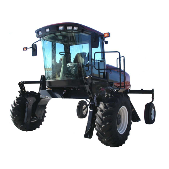
- Page 1 M100 Self-Propelled Windrower UNLOADING & ASSEMBLY INSTRUCTIONS NORTH AMERICAN SHIPMENTS Form # 169390 Model Year - 2010...
- Page 2 MACDON M100 SELF PROPELLED WINDROWER Form # 169390 Model Year - 2010...
-
Page 3: Table Of Contents
INTRODUCTION This instruction describes the unloading, set-up and pre-delivery requirements for the MacDon M100 Self- Propelled Windrower. Use the table of contents to guide you to specific areas. Retain this instruction for future reference. CAREFULLY READ ALL THE MATERIAL PROVIDED BEFORE ATTEMPTING TO UNLOAD, ASSEMBLE, OR USE THE MACHINE. - Page 4 VII. OPERATOR’S PRESENCE SYSTEM CHECKS....................41 VIII. EXTERIOR LIGHTS ............................41 INTERIOR LIGHTS ............................42 A/C AND HEATER ............................43 MANUALS..............................43 CAB INTERIOR ............................43 Form # 169390 Model Year - 2010...
-
Page 5: General Safety
• Provide a first-aid kit for use in case of GENERAL SAFETY emergencies. CAUTION following general farm safety precautions that should be part of your operating procedure types machinery. • Keep a fire extinguisher on the machine. Be sure the extinguisher is properly maintained and be familiar with its proper use. - Page 6 • Stop engine and remove key from ignition before leaving operator's seat for any reason. A child or even a pet could engage an idling machine. • Keep the area used servicing machinery clean and dry. oily floors slippery. spots can be dangerous when working with electrical equipment.
-
Page 7: Recommended Torques
C. METRIC BOLTS RECOMMENDED TORQUES NC BOLT TORQUE* A. GENERAL BOLT 10.9 DIA. "A" The tables shown below give correct torque lbf·ft N·m lbf·ft N·m values for various bolts and capscrews. • Tighten all bolts to the torques specified in chart unless otherwise noted throughout this manual. -
Page 8: Hydraulic Fittings
O-RING TYPE D. HYDRAULIC FITTINGS FITTING LOCKNUT FLARE TYPE WASHER O-RING FLARE GROOVE SEAT BODY FLARESEAT a. Check flare and flare seat for defects that might cause leakage. a. Inspect O-ring and seat for dirt or obvious b. Align tube with fitting before tightening. defects. -
Page 9: Conversion Chart
CONVERSION CHART INCH-POUND UNITS SI UNITS (METRIC) QUANTITY FACTOR UNIT NAME ABBR. UNIT NAME ABBR. Area acres acres x 0.4047 = hectares Flow US gallons per minute (gpm) x 3.7854 = liters per min L/min Force pounds force x 4.4482 = Newtons inch x 25.4 =... -
Page 10: Accronyms And Abbreviations
ACCRONYMS AND ABBREVIATIONS TERM DEFINITION American Petroleum Institute American Society Of Testing And ASTM Materials cubic centimeters Celsius Cab Display Module Fahrenheit ft/min feet per minute ft/s feet per second U.S. gallons per minute Ground Speed Lever horsepower inches cubic inches kilograms kilopascals lbf. -
Page 11: Step 1. Unload Windrower
UNLOADING AND ASSEMBLY STEP 1. UNLOAD WINDROWER CAUTION To avoid injury to bystanders from being struck by machinery, do not allow persons to stand in unloading area. A. TWO FORKLIFT METHOD CAUTION Equipment used for unloading must meet or exceed the requirements specified below. BOLTED FRAME SHOWN Using inadequate equipment may result in FIXED FRAME SIMILAR... -
Page 12: Single Forklift Method
UNLOADING AND ASSEMBLY Chains must be the same length. B. SINGLE FORKLIFT METHOD CAUTION METHOD 1 The front legs rest on the trailer bed on skid shoes. Ensure there are no obstructions to CAUTION prevent rearward sliding of the skid shoes and watch carefully that as unit is dragged, Equipment used for unloading must meet or the skid shoes are not sliding sideways... - Page 13 UNLOADING AND ASSEMBLY BOLTED FRAME SHOWN FIXED FRAME SIMILAR c. Position forklift on left or right side of trailer and position forks under windrower frame. NOTE Windrower center gravity approximately 55 in. (1397 mm) rearward of drive wheel center. WARNING Ensure forks project beyond far side of frame.
-
Page 14: Step 2. Reposition Rh Leg (Bolted Frame)
UNLOADING AND ASSEMBLY STEP 2. REPOSITION RH LEG (BOLTED FRAME) For Fixed Frame windrower, proceed to STEP 3 INSTALL FRONT WHEELS. Only right cab-forward requires repositioning from shipping to field configuration. a. Support the front of the windrower leg off the ground with stand (or equivalent). -
Page 15: Step 3. Install Front Wheels
UNLOADING AND ASSEMBLY STEP 3. INSTALL FRONT WHEELS e. Install wheel nuts and tighten to 175-200 ft·lbf (237-271 N·m) using the tightening sequence as shown. NOTE To avoid damage to wheel disks, do not over-tighten wheel nuts. Repeat sequence three times. a. -
Page 16: Step 4. Install Caster Wheels (Fixed Frame)
UNLOADING AND ASSEMBLY STEP 4. INSTALL CASTER WHEELS (FIXED FRAME) METHOD 1 55-58 in. (1400-1473 mm) FROM GROUND a. Support rear of windrower with a forklift or equivalent. Distance between walking beam and ground should be 55-58 in. (1400-1473 mm). d. -
Page 17: Method 2
UNLOADING AND ASSEMBLY METHOD 2 55-58 in. (1400-1473 mm) FROM GROUND a. Support rear of windrower with jack stands under the rear frame or with a support under the shipping stand. Distance between walking beam and ground should be 55-58 in. (1400- 1473 mm). -
Page 18: Step 5. Reposition Caster Wheels (Bolted Frame)
UNLOADING AND ASSEMBLY STEP 5. REPOSITION CASTER WHEELS (BOLTED FRAME) As an option, the rear casters can be adjusted to a narrow tread width to allow loading and shipping without having to remove them. narrow tread width also suits smaller headers by allowing more space to the uncut crop and provides more maneuverability around poles, irrigation inlets, or other obstacles. -
Page 19: Step 6. Install Steps
UNLOADING AND ASSEMBLY STEP 6. INSTALL STEPS STEP 7. INSTALL CENTER LINK MECHANICAL LINK a. Remove clevis pin from center link. a. Install two ½ in. x 1.0 hex bolts in upper holes in platform. Do not thread in fully. b. -
Page 20: Step 8. Install Battery
UNLOADING AND ASSEMBLY STEP 8. INSTALL BATTERY RATING GROUP CCA VOLT MAX. DIMENSION Heavy Duty, Off-Road, 13x6.81 x9.43 in. BCI 31A Vibration (330x173x240 mm) Resistant a. Open engine compartment hood to highest position. b. Remove cable ties securing battery clamps and cables to frame. -
Page 21: Step 9. Install Am/Fm Radio
UNLOADING AND ASSEMBLY STEP 9. INSTALL AM/FM RADIO e. Locate receptacle (F) (supplied with radio) in opening and secure by bending tabs (G) on Provision has been made for installation of receptacle against panel. AM/FM radio. The mounting is designed to fit a DIN E style radio with a depth X=161 mm and having a 5 mm threaded stud centered on the rear for support. -
Page 22: Step 10. Attach Header
UNLOADING AND ASSEMBLY STEP 10. ATTACH HEADER A. HEADER ATTACHMENT - D SERIES IMPORTANT A light header float kit may need to be installed, depending on the header size and configuration. 2. Locate boot (D) on lift linkage (E) and reinstall pin (C). - Page 23 UNLOADING AND ASSEMBLY MECHANICAL LINK – M150 HEADER UP HEADER HEADER TILT UP TILT DOWN HEADER DOWN 1. Loosen nut (H) and rotate barrel (J) to adjust length so that link lines up with header bracket. c. Start the engine and activate header down 2.
- Page 24 UNLOADING AND ASSEMBLY 3. Push down on rod end of link cylinder (K) Remove pin from storage position (N) in linkage until hook engages pin on header and is and insert in hole (O) to engage float springs. locked. Check that center link is locked onto Secure with hairpin.
- Page 25 UNLOADING AND ASSEMBLY REEL HYDRAULICS q. Connect reel hydraulics (R) at RH side of windrower. Refer Draper Header Operator’s Manual. Form # 169390 Model Year - 2010...
-
Page 26: Header Attachment - A Series
UNLOADING AND ASSEMBLY CAUTION B. HEADER ATTACHMENT – A SERIES Check to be sure all bystanders have cleared the area. HEADER UP HEADER DOWN b. Start the engine and activate header down button on the GSL to fully retract header lift cylinders. - Page 27 UNLOADING AND ASSEMBLY e. Connect center link as follows: MECHANICAL LINK – M150 HEADER UP HEADER HEADER TILT UP TILT DOWN HEADER DOWN 1. Loosen nut (F) and rotate barrel (G) to adjust length so that other end lines up with header bracket.
- Page 28 UNLOADING AND ASSEMBLY m. Disengage lift cylinder stops. n. Start engine, and activate header lift cylinder switch on GSL to lower header fully. Stop engine and remove key. h. Install pin (A) through each boot and foot and secure with hairpin.. IMPORTANT Ensure pin (A) is fully inserted and hairpin is installed behind bracket.
-
Page 29: Step 11. Lubricate Machine
UNLOADING AND ASSEMBLY STEP 11. LUBRICATE MACHINE Recommended Lubricant SPEC DESCRIPTION High Temp. Extreme Pressure As Required (EP2) Performance With SAE Multi- Unless 1% Max Molybdenum Disulphide Purpose. Otherwise (NLGI Grade 2). Specified. Lithium Base DANGER Stop engine and remove key from ignition before leaving operator's seat for any reason. - Page 30 UNLOADING AND ASSEMBLY Lubrication Points (continued) High Temp. Extreme Pressure (EP2) Performance With 1% Max Molybdenum Disulphide (NLGI Grade 2). Lithium Base CASTER PIVOT (BOTH SIDES) TOP LINK – TWO FITTINGS (BOTH SIDES) FORMED CASTER WHEEL BEARING 1 PLACE (BOTH WHEELS) FORKED CASTER SPINDLE BEARINGS TWO PLACES (BOTH WHEELS) WALKING BEAM PIVOT...
-
Page 31: Step 12. Program Cdm
UNLOADING AND ASSEMBLY c. Press SELECT. TRACTOR SETUP? STEP 12. PROGRAM CDM displayed on upper line. The monitoring system requires programming d. Press and then SELECT. for each header and the header must be e. HEADER TYPE? is displayed. DRAPER is attached to the windrower. - Page 32 UNLOADING AND ASSEMBLY DETAILED PROGRAMMING INSTRUCTIONS (Key On / Engine Running or Not / Header Disengaged). (Press PROGRAM and SELECT on CDM to enter programming mode). Programming Menu Flow Chart L1 C x x x || T R A C T O R S E T U P ? If "NO"...
- Page 33 UNLOADING AND ASSEMBLY C x x x || V I E W If "NO" then jump to: C O N T R O L L O C K S ? M x x x || N O / Y E S E X I T T R A C T O R S E T U P ?
- Page 34 UNLOADING AND ASSEMBLY C x x x || T O C A L I B R A T E S E L E C T The menu will display the last item selected when the M x x x || calibration routine is completed.
- Page 35 UNLOADING AND ASSEMBLY C x x x || R E A D If "NO" then jump to: S E N S O R I N P U T S ? M x x x || N O / Y E S A C T I V A T E F U N C T I O N S ? C x x x || S E N S O R...
-
Page 36: Step 13. Set Knife Speed
UNLOADING AND ASSEMBLY 3. Multiply the rpm reading by two for the knife STEP 13. SET KNIFE SPEED speed in strokes per minute. b. Determine the knife speed as follows if the The knife speed is manually set by making machine is equipped with the optional module: adjustments to the knife drive pump and has 1. - Page 37 UNLOADING AND ASSEMBLY 3. Turn adjuster screw (B) clockwise (screw in) to decrease knife speed, and counter- clockwise (screw out) to increase the knife speed. NOTE One turn of the adjuster screw will change knife speed approximately 116 strokes per minute, or the wobble box pulley speed by 58 revolutions per minute.
-
Page 38: Step 14. Perform Pre-Delivery Checks
PRE-DELIVERY CHECKS C. TIRE PRESSURES STEP 14. PERFORM PRE- Measure tire pressure with a gauge. DELIVERY CHECKS Bar – 32 psi (221 kPa) WARNING Turf – 20 psi (138 kPa) Caster - 10 psi (69 kPa) Stop windrower engine and remove key D. -
Page 39: Hydraulic Oil Level
PRE-DELIVERY CHECKS F. HYDRAULIC OIL LEVEL H. A/C COMPRESSOR BELT b. Turn filler cap counterclockwise to loosen bung, and remove dipstick. a. Tension on A/C compressor belt should be such that a force of 8 to 12 lbf (35-55 N) deflects the belt 3/16 in. -
Page 40: Perform Safety System Checks
5. Try to start the engine. The CDM will flash If the system does not function as described “CENTER STEERING”, accompanied by a above, refer to the M100 Operator’s Manual for short beep with each flash, and the engine adjustment procedures. -
Page 41: Operational Checks
Move GSL to neutral. Move steering wheel to locked a. Start engine as follows: position. Disengage header clutch. Neutral interlock Refer to the M100 Operator’s misadjusted. Manual. No fuel to engine. Fill empty fuel tank, replace clogged filter. Old fuel in tank. -
Page 42: Cdm Display
PRE-DELIVERY CHECKS c. Cold Start Engine temperature 20°F NOTE (-7°C) or lower. Throttle is non-responsive during this time as engine is in “warm up” mode. NOTE This mode lasts from 30 seconds to 3 Grid heater will not operate if engine minutes depending on temperature. -
Page 43: Operator's Presence System Checks
In approximately 5 seconds the header should shut off. If not, the operator presence system requires adjustment, refer to the M100 Operator’s Manual for adjustment procedures. NOTE To restart the header, move the header engage switch “OFF”... -
Page 44: Interior Lights
PRE-DELIVERY CHECKS c. Switch on road lights and check that all lights shown are functioning. BEACON LIGHTS - AMBER HI/LO LIGHTS Switch on beacons (if installed) and check that TURN SIGNALS/HAZARDS - AMBER they are functioning. The ignition switch must FRONT be at RUN but the engine does not need to be running. -
Page 45: A/C And Heater
BLOWER SWITCH Controls Blower Speed OFF/LO/MEDIUM/HI a. The following manuals should be stored in the manual storage compartment behind operator’s seat: • M100 Self-Propelled Windrower PARTS CATALOG. See below. • M100 Self-Propelled Windrower OPERATOR’S MANUAL. See below. AIR CONDITIONING SWITCH OPERATOR’S... - Page 46 NOTES Form # 169390 Model Year - 2010...
- Page 47 NOTES Form # 169390 Model Year - 2010...
- Page 48 MacDon Inc. 10708 N. Pomona Avenue Kansas City, Missouri United States, 64153-1924 t. (816) 891-7313 f. (816) 891-7323 MacDon Australia Pty. Ltd. A.C.N. 079 393 721 P.O. Box 243 Suite 3, 143 Main Street Greensborough, Victoria Australia 3088 t. 03 9432 9982 f.
- Page 49 M100 Self-Propelled Windrower Pre-Delivery Checklist – N.A. Perform these checks and adjustments prior to delivery to your customer. The completed checklist should be retained either by the operator or the dealer. CAUTION: Carefully follow the instructions given. Be alert for safety related messages which bring your attention to hazards and unsafe practices.
Need help?
Do you have a question about the M100 and is the answer not in the manual?
Questions and answers