Table of Contents
Advertisement
Quick Links
Advertisement
Table of Contents

Related Manuals for Teledyne CombiFlash Rf


Summary of Contents for Teledyne CombiFlash Rf
- Page 1 CombiFlash ® User Manual For indoor use only COPYRIGHT © 2013 by Teledyne Isco 4700 Superior St. Lincoln, Nebraska, U.S.A. 68504 Phone: (402) 464-0231 Toll Free: (800) 228-4373 FAX: (402) 465-3022 Revision C, May 2015 Part #69-5233-650...
- Page 2 CombiFlash® Rf User Manual...
-
Page 3: Table Of Contents
1.4 Specifications ....... 1-9 1.5 Controls, Indicators, and Features of the CombiFlash Rf . - Page 4 4.4 Connect Solvent Lines ..... . . 4-3 4.4.1 Connecting the CombiFlash Rf with 4x Module . 4.4.2 Connecting the CombiFlash Rf with 4x Module and PurIon .
- Page 5 Table of Contents 4.8 Remove Shipping Hardware ....4-13 4.9 Turn on Power ......4-14 4.10 Prime the Solvent Lines .
- Page 6 6.4.10 Viewing runs ......6-58 6.4.11 Manual Control of the CombiFlash Rf ..6-61 6.4.12 Setting the Vapor Limit.
- Page 7 Table of Contents 8.6.7 ESI and APCI Replacement from PurIon S and PurIon L ......8-15 8.6.8 Cleaning the Ionization Source Capillary .
- Page 8 CombiFlash® Rf User Manual viii...
-
Page 9: Introduction
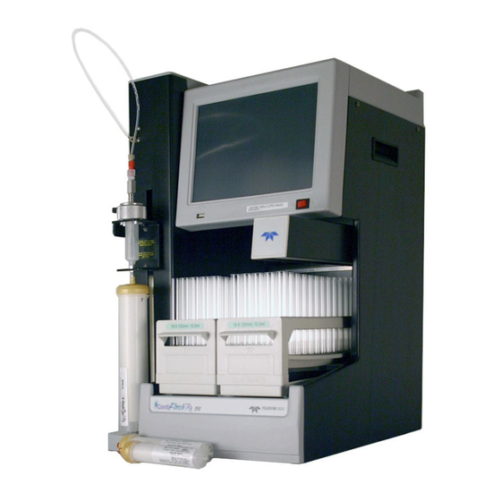
• Installation instructions, including connections with Windows and iOS operating systems • Certification and warranty information Once you are operating the CombiFlash Rf, you may refer to the Help menu for operating instructions. Note This Installation Guide will use the term “CombiFlash Rf” when the context applies to all systems (including the EZ Prep systems which are based in the Rf platform). - Page 10 User Manual The CombiFlash Rf system is available in different configurations: Figure 1-1 CombiFlash Rf 150 system, 10–100 mL/min, 150 psi (without injection valve) CombiFlash Rf 150 – For general purpose Flash chromatog- raphy needs, the CombiFlash Rf is a 10–100 mL/min, 150 psi system that pumps two solvents to form a binary gradi- ent.
- Page 11 Section 1 Introduction Figure 1-2 CombiFlash Rf system, 1–200 mL/min, 200 psi (with automatic injection valve) CombiFlash Rf – For more advanced needs, the Combi- Flash Rf is a 1–200 mL/min (delivery flow rate), 200 psi system that forms a binary gradient by automatically selecting two solvents from four inlets.
- Page 12 CombiFlash® Rf User Manual Figure 1-3 CombiFlash Rf Lumen system, with evaporative light scattering and UV (or UV-vis) detection CombiFlash Rf Lumen – This system has the same high performance features as the Rf system, but includes an internal evaporative light scattering detector (ELSD). Dur- ing operation, this detector can be combined with the UV (200–400 nm) or UV-vis (200–800 nm) detection to isolate...
- Page 13 Section 1 Introduction Figure 1-4 CombiFlash Rf PurIon CombiFlash PurIon – This system has the same features as the Rf but includes a mass spectrometer with a detection range of 50 to 1200 Daltons (Da) (PurIon, PurIon S) or 50-2000 Da (PurIon L systems). During purification, this...
- Page 14 CombiFlash® Rf User Manual Figure 1-5 CombiFlash EZ Prep system CombiFlash EZ Prep – This system takes the Rf system to the next level of performance by including the capability to perform Preparative HPLC separations on the same sys- tem used for flash chromatography. It is available with all the detector combinations of the Rf including UV, UV-Vis, Evaporative Light Scattering, and the PurIon mass spec-...
- Page 15 Rf or Rf Lumen system. This configura- tion is known as the CombiFlash Rf 4x system, a fully auto- mated four channel Flash chromatography system. The four channels are independent—including separate waste containers with full bottle detection.
-
Page 16: Operating Overview
CombiFlash® Rf User Manual 1.3 Operating Overview The CombiFlash Rf system is equipped with a touch screen display for local control. The system supports TCP/IP communication. This allows direct control of the system by a Windows computer via a cross-over cable between Ethernet ports of the CombiFlash Rf system and the computer. -
Page 17: Specifications
Section 1 Introduction 1.4 Specifications Table 1-1 CombiFlash Rf 150 and Rf System Specifications Rf 150 Systems Systems (Without Inject Valve) (With Inject Valve) Overall Dimensions 61 x 36 x 43 cm (24 x 14.1 x 17") (HWD) Weight 22.3 kg (49.2 lbs) 24.5 kg (54 lbs) - Page 18 CombiFlash® Rf User Manual Table 1-1 CombiFlash Rf 150 and Rf System Specifications (Continued) UV Detection 200 to 400 nm, optional 200 to 800 nm UV-Vis Wavelength Monitor Wavelength Optional 200 to 400 nm, optional with Purity Ratio 200 to 800 nm UV-Vis Wavelength Accuracy ±5 nm...
- Page 19 Section 1 Introduction Table 1-2 CombiFlash Rf Lumen Specifications Dimensions 61 cm (24")36 cm (14.1")43 cm (17") (HWD) Weight 30.75 kg (67.8 lbs) Input voltage range from 100 to 240 VAC, 50/60 Hz, Power Options 2.0 Amps system maximum. Line cord is the disconnect device.
- Page 20 CombiFlash® Rf User Manual Table 1-2 CombiFlash Rf Lumen Specifications (Continued) Split Flow Rate 0.75 mL/min, ±10% ±[2mL (flow rate 60)] Fraction Accuracy Electrical Safety per EN 61010-1 Pollution Degree Installation Category Maximum Altitude 2000 meters Note 1. All specifications are subject to change.
- Page 21 System Specifications Dimensions (H x W x D) CombiFlash Rf: 24 x 14 x 17 in (60 x 36 x 43 cm) Mass Spectrometer 26 x 11 x 22 in (66 x 28 x 56 cm) Roughing Pump 10 x 9 x 18 in (26 x 23 x 46 cm)
- Page 22 CombiFlash® Rf User Manual Table 1-4 CombiFlash Rf + 4x System Specifications (Continued) Input voltage range from 100 to 240 VAC, 50/60 Hz, Power Options 2.5 Amps system maximum, 0.5 amps module maximum. Line cord is the disconnect device. Line Frequency...
- Page 23 Section 1 Introduction Table 1-4 CombiFlash Rf + 4x System Specifications (Continued) Electrical Safety per EN 61010-1 Pollution Degree Installation Category Maximum Altitude 2000 meters Note 1. All specifications are subject to change. Note 2. For columns undetected by RFID, the max pressure is limited to 50 psi.
- Page 24 CombiFlash® Rf User Manual Table 1-5 CombiFlash EZ Prep Specifications (Continued) Peak Detection Modes Slope, Threshold, or Time Windows Flow Cell Path Length .1 mm, ±.025mm. Optional .2mm, .3mm, .5mm, 1mm, and 2mm. UV Detection and Selectable from 200 to 400 nm range. Optional 200 to Monitor Wavelength 800 nm UV-Vis detector.
- Page 25 Section 1 Introduction Table 1-6 Component Materials List Component Materials Teledyne Isco RediSep Virgin Polypropylene, silica-based media (alumina Rf Cartridge columns also available), polyethylene (HDPE) frits Process Tubing Fluoropolymer, Carbon impregnated fluoropolymer tubing and 316 stainless steel tubing Drain Tubing...
-
Page 26: Controls, Indicators, And Features Of The Combiflash Rf
1.5 Controls, Indicators, and Features of the CombiFlash Rf Figures 1-7 through 1-9 illustrate the controls on the CombiFlash Rf (including the EZ Prep). Figure 1-7 CombiFlash Rf Features (Front) 1. Touch Panel LCD display – Large 10.5 inch display for system monitoring and control. - Page 27 (shown) or a liquid injection using a syringe or similar device. 8. Injection Valve – This six-way valve is automatically positioned by the CombiFlash Rf according to its current mode of operation. Modes include column equilibration, sample injection, elution, column flushing, valve cleaning, and system purging.
- Page 28 CombiFlash® Rf User Manual Figure 1-8 CombiFlash Rf Features (Side) Figure 1-9 CombiFlash Rf Features (Back) 13. Upper Drain Tube – Liquids spilled on the top shelf are carried away through this tube to a user-supplied container. 14. External Detector (All systems except the Rf 150 and Lumen) –...
- Page 29 Section 1 Introduction 15. Ethernet Port – An 8P8C jack for a network connection using a standard CAT5 cable, or for a direct connection to a computer using a cross-over cable. 16. USB Port – For control of peripheral equipment such as the Rf 4x or PurIon mass spectrometer detector.
- Page 30 Refer to Fig. 1-9 for other back panel features. Figure 1-10 CombiFlash Rf Lumen ELSD Features (Back) 26. Nitrogen Inlet – (Rf Lumen only) Connects to the carrier gas supply (60 to 70 psig). 27.External Detector – (Rf Lumen only) Reserved for future use.
- Page 31 CAUTION Discontinue use of the CombiFlash Rf Lumen if liquid is present at the Pump Drain. Contact Teledyne Isco technical service for assistance with correcting the leak. Figure 1-11 Optional CombiFlash Rf 4x Module Features (Back) 30. Waste Level Sense – The system uses air or user-supplied gas to measure the hydrostatic pressure of the waste above the level sense line end.
- Page 32 CombiFlash® Rf User Manual 33. Valve Waste Out – The injection valves on channels 2 through 4 are cleaned after each run. The system directs fluids from this automatic cleaning routine to this shared port. 34. A B – Reserved for future use. 35.
-
Page 33: Safety
OSHA Guide 1910.1000. To reduce those levels to a safe exposure, Teledyne Isco recommends that you place the system in a laboratory hood designed for the purpose of ventilation. This hood should be constructed and operated in accordance with federal state and local regulations. -
Page 34: Hazard Severity Levels
CombiFlash® Rf User Manual 100 g meet Pressure Vessel Directive 97/23/EC. Teledyne Isco strongly recommends against the use of columns rated less than 210 psi (1448 kPa). 1.6.1 Hazard Severity Levels This manual applies Hazard Severity Levels to the safety alerts. - Page 35 Section 1 Introduction Table 1-7 Hazard Symbols Warnings and Cautions The exclamation point within the triangle is a warning sign alerting you of important instructions in the instrument’s technical reference manual. The lightning flash and arrowhead within the triangle is a warning sign alerting you of “dangerous voltage”...
-
Page 36: For Additional Information
Punto del machacamiento. Sus dedos o manos seriusly serán dañados si usted los coloca entre las piezas móviles cerca de estos símbolos. 1.7 For Additional Information Technical assistance for the CombiFlash Rf system can be obtained from: Teledyne Isco 4700 Superior St. -
Page 37: Preparation
User Manual Section 2 Preparation: Rf + , Rf + Lumen, Rf + PurIon, and EZ Prep Systems This section provides instructions for unpacking and installing the CombiFlash Rf , Rf Lumen, Rf PurIon, and EZ Prep systems. The Rf PurIon has supplementary instructions for installation of the PurIon Mass Spectrometer. - Page 38 WARNING If there is any evidence that the system has been damaged in shipping, do not plug it into AC power. Contact Teledyne Isco or its authorized representative for advice. Compare the contents of the boxes with the enclosed packing slips.
-
Page 39: Instrument Location
WARNING The system is heavy. Use a two-person lift to prevent injury. Before making any connections to the CombiFlash Rf system, place it on the bench or in the fume hood where it will be operated. Temporarily position the system so you can access the back panels to complete the connections. -
Page 40: Connect Solvent Lines (Excludes Ez Prep)
CombiFlash® Rf User Manual 2.4 Connect Solvent Lines (Excludes EZ Prep) WARNING Risk of fire ignited by electrostatic discharge. Never substitute the black tubing on CombiFlash systems. The black tubing (P/N 023-0503-06) is conductive. This tubing is required to dissipate static electricity. To Solvent Supply To Solvent Level Sensing Connection... - Page 41 Containers should be thoroughly cleaned before each refill. Failure to clean the containers may result in damage to the solvent selection valve and internal components. The CombiFlash Rf and Rf Lumen systems have four solvent inlet ports on the back panel, labeled 1-4.
-
Page 42: Connect Waste Lines (Excludes Ez Prep)
When using higher-density solvents such as dichloromethane (DCM), place the solvent container level with or above the CombiFlash Rf system. Placing solvent containers below the level of the system can contribute to decreased flow due to the high vapor pressure of DCM. This problem becomes more pronounced as the ambient temperature increases. - Page 43 Section 2 Preparation: Rf + , Rf + Lumen, Rf+ PurIon, and EZ Prep Systems To Diverter Valve Waste Connection To Waste Level To Inject Valve Waste Sense Connection Connection 60-0923-017 Ferrule 60-0923-015 Compression Fitting Nut 60-5234-143 Waste Tubing Assembly Ventilation Hole (Luer fitting) If necessary, connect...
- Page 44 CombiFlash® Rf User Manual The accessory package includes parts to complete the waste connections. Figure 2-3 shows the recommended connections for user-supplied waste containers with either a 38 or 45 mm opening (GL 38 or GL 45). Refer to the steps in section 2.4 to connect the tubing to the system using the compression fittings.
-
Page 45: Ez Prep Plumbing Connections
Section 2 Preparation: Rf + , Rf + Lumen, Rf+ PurIon, and EZ Prep Systems 2.6 EZ Prep Plumbing Connections The EZ Prep comes with the solvent inlet lines and waste lines pre-assembled to the instrument. To install the EZ Prep: 1. -
Page 46: External Gas
When using higher-density solvents such as dichloromethane (DCM), place the solvent container level with or above the CombiFlash Rf system. Placing solvent containers below the level of the system can contribute to decreased flow due to the high vapor pressure of DCM. This problem becomes more pronounced as the ambient temperature increases. -
Page 47: Combiflash Rf
Improper draining may damage the instrument’s internal components. The CombiFlash Rf system has drain tubes extending from its back panel. The tubes drain away any liquid spilled on the top shelf (Rf only) and the tray beneath the fraction collection racks. - Page 48 CombiFlash® Rf User Manual Vacuum or pressurized air applied to the outlet end of the drain tube must exist at the collection tray drain hole. Figure 2-5 Fraction Collector Drain only –Vacuum or pressurized air applied to the outlet end of the drain tube must exist at the top shelf drain hole.
- Page 49 Route this extension tubing to the waste collection vessel. (CombiFlash Rf Lumen and EZ Prep with optional ELSD only) The CombiFlash Rf Lumen system has additional drains that must be connected: ...
-
Page 50: Position The System
CAUTION Discontinue use of the CombiFlash Rf Lumen if liquid is present at the Pump Drain. Contact Teledyne Isco technical service for assistance with correcting the leak. 2.9 Position the System After completing the various connections, the system can be moved to its operating position. -
Page 51: Install Collection Tube Racks
Section 2 Preparation: Rf + , Rf + Lumen, Rf+ PurIon, and EZ Prep Systems 2.10 Install Collection Tube Racks Before beginning a run, you must load collection racks with tubes onto the system’s fraction collector tray. Your system was shipped with two collection tube racks. The following tube rack sets are available: •... - Page 52 CombiFlash® Rf User Manual Figure 2-7 Loading test tubes 2-16...
-
Page 53: External Detector (Optional)
–1.2 to +1.2 volts, although custom interface cables may convert other analog signals to this range. Contact the factory for interface and fluid path options. Note The external detector option is not supported on CombiFlash Rf Lumen systems. 2-17... -
Page 54: Turn On Power
CombiFlash® Rf User Manual 2.12 Turn on Power The system’s power switch is located just below the touch screen panel. 1. Turn the switch to the ON position. The system will begin its startup routine which includes self diagnostics. 2. Monitor the movement of the fraction collector arm. The arm should move to the left rear corner of the fraction collector area. -
Page 55: Enable Automatic Phase Change (Ez Prep Only)
Section 2 Preparation: Rf + , Rf + Lumen, Rf+ PurIon, and EZ Prep Systems Note The system is shipped with common solvent names already loaded. If your solvent names are listed in the solvent drop-down list boxes, skip steps 1 through 3. 1. -
Page 56: General Settings
4 is the strong reverse phase solvent (such as methanol or acetonitrile). 2.13.3 General Settings CombiFlash Rf Name (optional) – Use this option to name your system. The name will appear in operational displays and run summaries. This feature is useful when your laboratory has more than one CombiFlash Rf system. -
Page 57: Set Default Tube Volumes
Section 2 Preparation: Rf + , Rf + Lumen, Rf+ PurIon, and EZ Prep Systems • Ensure that there is no visible solvent leakage from the system. If PeakTrak continues to display the Vapor Limit alarm after you have made these checks and corrected any problems found, it is likely that organic vapors are present in the ambi- ent environment of your laboratory. - Page 58 CombiFlash® Rf User Manual settings are discussed in Section 7, R . Do not EMOTE NTERFACES select this option for these initial installation steps. Default Run Units – Run units are displayed along the X-axis of the chromatogram. Select Time (in minutes) or Column Volumes.
- Page 59 Section 2 Preparation: Rf + , Rf + Lumen, Rf+ PurIon, and EZ Prep Systems a peak after an extension, the system will add another, up to a maximum of three extensions. Occasionally, compounds might come off the column once the %B returns to the minimum value at the end of a run.
-
Page 60: Prep Hplc Tab
CombiFlash® Rf User Manual Use ELSD by Default - causes all runs to use the ELSD detector unless disabled in the run requirement screen TARTING A RUN USING DEFAULT SETTINGS [6.4.1] 2.13.8 Prep HPLC Tab allows selection of the most commonly DEFAULT COLUMN used Preparative HPLC column. -
Page 61: Restart The System
Section 2 Preparation: Rf + , Rf + Lumen, Rf+ PurIon, and EZ Prep Systems box. The column definition can be saved with a new name using S . The newly created column definition can be edited in the same manner as when creating a new column. -
Page 62: Prime The Solvent Lines
CombiFlash® Rf User Manual 2.14 Prime the Solvent Lines Before the first use, the system should be primed. Ensure that the solvent containers are filled, then: 1. Select the “Tools>Auto prime” menu command. 2. There are 4 solvent selection lists labeled from 1st solvent through 4th solvent, describing the order in which solvents will be pumped. -
Page 63: System Verification
This tests all EZ Prep system functions also. To do so, use a pre-packaged CombiFlash Rf test kit: • Part number 60-5237-050 Test kit containing five of the 5 gram size solid load cartridges pre-filled with 0.5 grams of test sample... -
Page 64: Installation Qualification Checklist
CombiFlash® Rf User Manual 2.16 Installation Qualification Checklist Table 2-1 may be completed to verify and document the installation procedures contained in Section 2 of this guide. See following page: 2-28... - Page 65 Section 2 Preparation: Rf + , Rf + Lumen, Rf+ PurIon, and EZ Prep Systems Table 2-1 Installation Qualification Checklist Installer Operator Step Description Initials Initials NPACKING THE NSTRUMENT OCATION ONNECT OWER ONNECT OLVENT INES EZ P XCLUDES ONNECT ASTE INES EZ P XCLUDES...
-
Page 66: Preparation: Rf 150 Systems
3.1 Unpacking the Unit The CombiFlash Rf 150 system is shipped in a single carton. Carefully unpack the shipment and inspect the contents. WARNING The system is heavy. Use a two-person lift to prevent injury. - Page 67 WARNING If there is any evidence that the system has been damaged in shipping, do not plug it into AC power. Contact Teledyne Isco or its authorized representative for advice. Compare the contents of the box with the enclosed packing slips.
-
Page 68: Instrument Location
1550 square centimeters (240 in ) of level bench space. Ensure that the CombiFlash Rf has at least 3 cm (1.25") of air space behind it for ventilation. Additional space may be required for solvent and waste containers. -
Page 69: Connect Solvent Lines
To prevent damage or premature wear to the pump and internal valves, clean solvent should be used. The solvent should not contain any dissolved solids. The CombiFlash Rf 150 system has two solvent inlet ports on the back panel: one A solvent and one B solvent (Figure 3-2). Solvent... - Page 70 When using higher-density solvents such as dichloromethane (DCM), place the solvent container level with or above the CombiFlash Rf system. Placing solvent containers below the level of the system can contribute to decreased flow due to the high vapor pressure of DCM. This problem becomes more pronounced...
-
Page 71: Connect Waste Lines
CombiFlash® Rf User Manual 3.5 Connect Waste Lines WARNING Risk of fire or equipment damage. Failure to connect Waste Port tubing may allow organic solvents to pool in unsafe areas, possibly creating dangerous levels of flammable vapors. WARNING Risk of fire ignited by electrostatic discharges. Never substitute the black tubing on CombiFlash systems. -
Page 72: Connect And Route Drain Lines
Section 3 Preparation: Rf 150 Systems Figure 3-3 Preparing a bulkhead fitting connection b. Fully insert the tubing into the threaded bulkhead fitting on the back panel of the system. c. Finger-tighten the nut onto the threaded bulkhead fitting. This will seat the ferrule in the fitting. 2. - Page 73 CombiFlash® Rf User Manual The CombiFlash Rf 150 system has drain tubes extending from its top shelf and back panel. The tubes drain away any liquid spilled on the top shelf and the tray beneath the fraction collection racks. 1. Test the fraction collector drain by connecting a vacuum or air supply source to the outlet end of the drain tube.
-
Page 74: Position The System
(Figure 1-7). Use care not to damage the connections, tubing, and cables while moving the system. CAUTION Ensure that the CombiFlash Rf has at least 3 cm (1.25") of air space behind it for ventilation. Position the solvent and waste containers as necessary. -
Page 75: Install Collection Tube Racks
CombiFlash® Rf User Manual 3.8 Install Collection Tube Racks Before beginning a run, you must load collection racks with tubes onto the system’s fraction collector tray. Your system was shipped with two collection tube racks. The following tube rack sets are available: •... - Page 76 Section 3 Preparation: Rf 150 Systems To load the racks: 1. Insert test tubes, vials, or bottles into the rack (Fig. 3-6). Figure 3-6 Loading test tubes CAUTION Risk of broken glass or equipment damage. Do not load test tubes longer than the length listed on the rack label.
-
Page 77: Turn On Power
CombiFlash® Rf User Manual CAUTION An incorrectly installed rack will cause the rack to be misaligned under the fraction collector arm. Misaligned racks might cause fractions to miss the tube opening or deposit in the wrong tube. Always ensure the tube size label is visible (that is, facing outward) and the rack is pushed in until it is seated. -
Page 78: Solvents
3. Repeat steps 1 and 2 for both solvents. 3.10.2 General Settings CombiFlash Rf Name (optional) – Use this option to name your system. The name will appear in operational displays and run summaries. This feature is useful when your laboratory has more than one CombiFlash Rf system. -
Page 79: Set Default Tube Volumes
CombiFlash® Rf User Manual alarm while the Vapor Limit is set at 25, perform the following checks on your laboratory and the instrument: • Ensure that no open containers or spills of organic solvent are in close proximity to the system. •... - Page 80 Section 3 Preparation: Rf 150 Systems Automatically Print Report at End of Run – if this option is enabled, the system will print a report at the end of each run. Note This option requires the system to be configured for network operation and a connection to a printer on the network.
- Page 81 CombiFlash® Rf User Manual Enable Run Length Extension – When enabled, this option automatically extends the run if a peak is eluting at the end of the maximum %B gradient. This ensures that a late-eluting peak fully comes off the column and is collected. An automatic run extension is a five-minute isocratic hold added to the end of the run’s maximum %B gradient profile.
-
Page 82: Restart The System
Section 3 Preparation: Rf 150 Systems Enable rapid equilibration – select this option to equilibrate the column at a high flow rate. Note Due to the high pressure that is possible during rapid equilibration, this option may not be desirable for some column media or purification methods. -
Page 83: Prime The Solvent Lines
3.12 System Verification It is recommended that the system operation be verified. To do so, use a pre-packaged CombiFlash Rf test kit: • Part number 60-5237-050 — Test kit containing five of the 5 gram size solid load cartridges pre-filled with 0.5 grams of test sample NPHE, five 4 gram RediSep Rf silica gel columns, and instructions. -
Page 84: Installation Qualification Checklist
Section 3 Preparation: Rf 150 Systems 3.13 Installation Qualification Checklist Table 3-1 Installation Qualification Checklist Installer Operator Step Description Initials Initials NPACKING THE NSTRUMENT OCATION ONNECT OWER ONNECT OLVENT INES ONNECT ASTE INES ONNECT AND OUTE RAIN INES OSITION THE YSTEM NSTALL OLLECTION... - Page 85 CombiFlash® Rf User Manual 3-20...
-
Page 86: Preparation: Optional 4X Module
The optional 4x module is not compatible with the CombiFlash Rf 75 system. 4.1 Unpacking the Unit The CombiFlash Rf 4x module is shipped in a single carton. Carefully unpack the shipment and inspect the contents. If there is any damage to the shipping carton or any components, contact the shipping agent and Teledyne Isco (or its authorized representative) immediately. -
Page 87: Instrument Location
The CombiFlash Rf system requires approximately 1550 square centimeters (240 in ) of level bench space. Ensure that the CombiFlash Rf has at least 3 cm (1.25") of air space behind it for ventilation. Additional space may be required for solvent and waste containers. -
Page 88: Connect Solvent Lines
To prevent damage or premature wear to the pump and internal valves, clean solvent should be used. The solvent should not contain any dissolved solids. The CombiFlash Rf system has four solvent ports on the left side panel. To complete the solvent connections: Front Figure 4-1 Labeled ports on CombiFlash Rf system side panel 4.4.1 Connecting the CombiFlash Rf with 4x Module... -
Page 89: And Purion
CombiFlash® Rf User Manual 4.4.2 Connecting the CombiFlash Rf with 4x Module and PurIon 1. Place the PurIon next to the Rf system, opposite the 4x module. See Figure 4-2. The Rf system is used as an example only. 4x module... -
Page 90: Connect Waste Lines
Section 4 Preparation: Optional 4x Module PurIon 4x module Figure 4-3 Coupler for connecting 4x tubing 4. Connect the other end of the shorter tubing assembly to the tee fitting on the back of the PurIon. 5. Connect the longer tubing assembly to the “D” port on the Rf and to the other side of the tee fitting on the back of the PurIon. - Page 91 CombiFlash® Rf User Manual • one inlet to receive diverter valve waste from the CombiFlash Rf system labeled Column Waste, From RF. • four waste outlets —one for each column channel, labeled Column Waste 1, 2, 3, and 4. • one Valve Waste outlet shared by channels 2 through 4 for automatic injection valve cleaning.
- Page 92 7) and complete step 8 to route the Valve Waste Out from the Rf 4x module to the common container. The waste tubing assembly connected to the back panel of the CombiFlash Rf system will route all waste fluids to the common collection container and sense the level.
- Page 93 (60-0923-017), connect this tubing between the CombiFlash Rf system’s Level Sense port and the Rf 4x module’s Waste Level Sense From Rf port. Level Sense (air) Waste Solvent Figure 4-6 CombiFlash Rf system to Rf 4x waste tubing connections (all other connections not shown)
- Page 94 Section 4 Preparation: Optional 4x Module To Rf 4x module To Rf 4x Module Column Waste connections Waste Level Sense 1, 2, 3, or 4 connections 1, 2, 3, or 4 Channel 1 Only: 60-0923-017 Ferrule To Rf system Inject Valve Waste 60-0923-015 See step 8 for details on Compression Fitting...
- Page 95 Waste Level Sense port labeled “1.” c. At the CombiFlash Rf system back panel, the black tubing should still be connected to the Inject Valve Waste port (from step 1). If not, reconnect the tubing.
- Page 96 Section 4 Preparation: Optional 4x Module (All other connections not shown) To Waste Bottle 1 Figure 4-8 Channel 1 waste tubing connections (All other connections not shown) Waste Bottle 2 Waste Waste Bottle 3 Bottle 4 Figure 4-9 Channels 2 through 4 waste tubing connections 8.
- Page 97 CombiFlash® Rf User Manual To Waste Bottle 2 Figure 4-10 Valve Waste Out routed to Channel 2 Note When using higher-density solvents such as dichloromethane (DCM), ensure that waste containers are no more than 3 feet below the supply solvent levels. Placing solvent containers above the system and waste containers on the floor may cause the internal check valves to open and allow solvent to flow through the system when in the standby state.
-
Page 98: Control Connection
CAUTION Use care not to damage the connections, tubing, and cables while moving the system. 1. Turn the CombiFlash Rf system so that the operator can access all of the front view features and controls (Figure 1-7). 2. Position the Rf 4x module along the left side of the CombiFlash Rf system. -
Page 99: Turn On Power
(one of three) Figure 4-11 Remove thumbscrews 4.9 Turn on Power Turn the CombiFlash Rf system switch to the ON position. The system will begin its startup routine which includes self diagnostics. During the startup routine, the system will detect the connected Rf 4x module and automatically configure the user interface to access the additional channels. -
Page 100: Prime The Solvent Lines
Section 4 Preparation: Optional 4x Module 4.10 Prime the Solvent Lines The Rf 4x module was factory tested with 1:1 water/isopropyl alcohol and subsequently purged with air. If residual fluids would affect your chromatography, prime all channels on the system. Channel 1 should have been primed during the installation steps in Section 2.14 (page 2-25). -
Page 101: System Verification
User Manual 4.11 System Verification It is recommended that the system operation be verified for each channel. To do so, use a pre-packaged CombiFlash Rf test kit: • Part number 60-5237-050 Test kit containing five of the 5 gram size solid load cartridges pre-filled with 0.5 grams of test sample... -
Page 102: Installation Qualification Checklist
Section 4 Preparation: Optional 4x Module 4.12 Installation Qualification Checklist Table 4-1 Installation Qualification Checklist Installer Operator Step Description Initials Initials NPACKING THE NSTRUMENT OCATION ONNECT OWER ONNECT OLVENT INES ONNECT ASTE INES ONTROL ONNECTION OSITION THE YSTEM EMOVE HIPPING ARDWARE URN ON OWER... - Page 103 CombiFlash® Rf User Manual 4-18...
-
Page 104: Operation
User Manual Section 5 Operation This section provides abbreviated operating instructions for the CombiFlash Rf systems. For complete instructions, refer to Help menu option from PeakTrak’s main menu. 5.1 Flash Sample Preparation Before starting a run, consider how the sample will be introduced to the column media. - Page 105 CombiFlash® Rf User Manual To prepare an empty solid sample cartridge: 1. Ensure the empty cartridge has a bottom frit. CAUTION Missing frits may cause equipment damage, UV detection problems, or increased maintenance. Frits prevent solids from entering the fluid path. 2.
- Page 106 Section 5 Operation After you have prepared the pre-filled or empty cartridge, place the solid sample cartridge on the system: 1. Attach the desired adjustable cartridge cap: • 60-5237-047, fits 2.5 and 5 gram solid load cartridges. • 60-5237-048, fits 12 and 20 gram solid load cartridges.
- Page 107 CombiFlash® Rf User Manual Figure 5-2 Insert the plunger to the bed Figure 5-3 Align and push cartridge into the cap, and then rotate the cartridge to secure it.
-
Page 108: Pre-Loading On Column
210 psi (1448 kPa). RediSep columns smaller than 100 g are CE certified using standard IEC61010-1 for use on the CombiFlash Rf. RediSep columns larger than 100 g meet Pressure Vessel Directive 97/23/EC. Teledyne Isco strongly recommends against the use of columns rated less than 210 psi (1448 kPa). -
Page 109: Start A Default Method
CombiFlash® Rf User Manual 4. To seal the column fittings, give the column a slight twist turn). Note After loading a RediSep Rf column, the system (with the exception of the Rf 150) will use RFID technology to automatically detect the media type and column size. - Page 110 Section 5 Operation have not yet prepared the sample. You must also specify the cartridge type and size (Column plan subscribers only). When you click the run button, the system will perform a column equilibration and then wait while you prepare the cartridge. After you have placed the cartridge on the system, click OK to continue with the run.
- Page 111 CombiFlash® Rf User Manual estimate during operation. Solvent level sensing is not available on the Rf 150 system. Note If the waste level sensing tube is inserted correctly into the waste container, Rf systems, including those equipped with 4x, will automatically suspend operation before an overflow condition might exist.
- Page 112 Section 5 Operation 8. Click OK and the run begins. The system responds according to the sample Loading Type selected in step 4. systems, including those equipped with 4x — • If you selected Solid (Pause), the system equilibrates the column with the starting %B and then waits while you prepare the solid sample load cartridge.
-
Page 113: During The Run
CombiFlash® Rf User Manual • ELSD- click this button to enable the evaporative light scattering detector (Lumen systems only) Rf 150 systems — • If you selected Equilibration, ensure that the solvent delivery tubing is connected to the injection port above the column. When you click the OK button, the system equilibrates the column and then waits. - Page 114 Section 5 Operation called an isocratic hold). Note that pausing the run extends the run length. While in the Paused state, you can resume the run by clicking the Play button, or stop the run by clicking the Stop button. If you resume the run, the system continues with the gradient curve at the %B when the system was paused.
- Page 115 CombiFlash® Rf User Manual • Liquid sample loaded onto column with air purge NOT enabled: If you suspend the run with the Stop button, remove the column and install the Prime Tube in its place. Manually purge the liquid lines by pressing Tools -> Manual Control ->...
-
Page 116: Bypassing The Solid Load Cartridge
Section 5 Operation 5.4.2 Bypassing the Solid Load Cartridge systems, including those equipped with 4x) Occasionally, impurities precipitate in the solid load cartridge as compounds are purified. This may cause high back pressures resulting in reduced flow rates and long run times. Clicking this button changes the injection valve position, which removes the cartridge from the solvent path and relieves the back pressure. -
Page 117: About Solvent Level Detection
5.4.3 About Solvent Level Detection When enabled in the T >Configuration window, OOLS CombiFlash Rf , Rf Lumen and Rf 4x systems will estimate the solvent volume usage by measuring the solvent level in the container and the monitoring the usage rate. The system continues to refine this estimate of available solvent during operation. - Page 118 Section 5 Operation The options available on the alert message will vary depending on when the condition occurs (before or during a run) and which method (measured level or estimated usage rate) indicated the condition. To clear the alert message, the user must select one of the options below.
-
Page 119: Ez Prep Operation
CombiFlash® Rf User Manual 5.5 EZ Prep Operation Flash separations on the EZ Prep system are identical to those performed on the Rf . Preparative HPLC separations have the same control capabilities as the flash separations with a few minor differences. 5.5.1 Column Mounting Note HPLC columns that have less than 100 psi back pressure may not... -
Page 120: Sample Preparation
To maximize sample recovery, a small amount of suitable solvent should be used to push the sample into the injection loop. An alternative injection port fitting is available from Teledyne Isco. This alternative port 5-17... -
Page 121: Starting The Separation
CombiFlash® Rf User Manual requires an injection syringe to use a 22 gauge blunt needle for injection. he adapter can be obtained as Teledyne Isco PN/29-9125-060. 5.5.3 Starting the Separation 1. On the main screen, press the RediSep drop down. -
Page 122: User Help Reference
® User Manual Section 6 User Help Reference The CombiFlash Rf system includes User Help topics that are available from the PeakTrak touchscreen or remote browser window. This section contains many of these topics that describe the PeakTrak interface and its use. -
Page 123: Method File
With the exception of the Rf 150, when PeakTrak is started, and every time a RediSep Rf column is inserted, the system loads a default method. A default method contains Teledyne Isco’s recommended basic and advanced settings for the use of... -
Page 124: Run File
Run files use an *.run filename extension. 6.1.4 How to get PeakTrak help PeakTrak help can be displayed by selecting Help>Help from PeakTrak’s menu. If you need additional help, refer to Teledyne Isco’s C ONTACT NFORMATION [ LINE 6.2 PeakTrak Menu Options... - Page 125 CombiFlash® Rf User Manual 6.2.1.1 New Select the New command to open a new method file. Rf150 The main window opens using the default method for the currently selected column. Rf+ systems PeakTrak will open the main window using the default program settings for the detected column size.
- Page 126 Section 6 User Help Reference Note Note: D are an exception and cannot be EFAULT ETHODS [6.1.2.1] overwritten by the Save Method command. If a default method is open and you attempt to save any modifications to that method, the F window appears so you can rename the method ILES [6.3.6] file.
- Page 127 CombiFlash® Rf User Manual (You can open, edit, and print TXT files with text editing or word processing software.) 6.2.1.9 Import Method Choose this command to load a Method file from an external source (see E ) onto the system’s XPORT ETHOD [6.2.1.10] internal storage.
-
Page 128: Method Editor
Section 6 User Help Reference 6.2.1.13 Logout Choose this command to logout of the system. After logging out, the system displays a login screen and waits for the next user to log in. 6.2.2 Method Editor Selecting the Method Editor menu command will open the window. -
Page 129: Tools
PeakTrak’s Tools menu has the following options: 6.2.4.1 Auto Prime/Valve Wash Choose this command to automatically prime the solvent pumps. On CombiFlash Rf+ systems, this feature will also wash the injection valve. When you select this command, the system opens the A window. - Page 130 Section 6 User Help Reference 6.2.4.4 Edit Defaults Choose this command to open the M ETHOD DITOR [6.3.2] window from which you can modify the default method files. To prevent tampering with the default column programs, access to this function can be password protected using the menu command.
-
Page 131: Help
6.2.5.4 Export Log Files During operation, the system writes operating data to a log file. Teledyne Isco service personnel can interpret this data to optimize system performance or to troubleshoot difficulties. Teledyne Isco recommends that you use the menu command only when advised by a qualified service technician. -
Page 132: Main Window
6.2.5.6 About PeakTrak Choose this command to view information about PeakTrak. 6.2.5.7 About Isco Choose this command to view contact information for Teledyne Isco. 6.3 PeakTrak Windows This section contains descriptions of the windows used for most PeakTrak tasks. - Page 133 OLLECTION pane. [6.3.1.5] Note Note: The main window is expanded for CombiFlash Rf 4x systems. The main window the displays the settings and views in four tabs, one for each column channel. A fifth tab — B ATCH [6.3.5] — contains the controls to run sequential separations.
- Page 134 Section 6 User Help Reference points to change the shape of the curve and use the buttons at the bottom of the plot area to insert and delete points. For complete instructions on defining gradient curves, see EFINING A RADIENT [6.4.5] To zoom in on part of the plot area, click the Zoom In button to enable the zoom action and then drag across the area of interest.
- Page 135 CombiFlash® Rf User Manual column media and size. The column should match the one that will be used for the run. You may override the detected column size by selecting a different size or media. See also: R OLUMN ELECTION UIDE and A BOUT...
- Page 136 Section 6 User Help Reference the run, the system continues the gradient curve from the %B when the system was paused. • Stop — This button suspends the entire run. Unlike the Paused state, the pump, peak detection, and fraction collection will not operate.
- Page 137 CombiFlash® Rf User Manual • All — Click this button to collect all fluids in the fraction collection tubes. • Peaks — Click this button to collect only eluted peaks in the fraction collection tubes. • None — Click this button to divert all fluids to the waste port.
-
Page 138: Method Editor
Section 6 User Help Reference 6.3.2 Method Editor The Method Editor window has several sections. The B UTTON at the top of the window gives you quick access to BAR [6.3.2.1] file operations, a G , and C RADIENT PTIMIZER [6.3.3] OLUMN (Rf+ systems, including those equipped with 4x). - Page 139 CombiFlash® Rf User Manual • Time to CV / CV to Time — Click this button to toggle the Run Length (X-axis) units between minutes and . You can configure OLUMN OLUMES [ LINE PeakTrak’s default Run Length units by changing the settings.
- Page 140 Section 6 User Help Reference from a previous run and to conserve collection tubes by diverting all fluids until the first peak is expected. Time Windows can limit the fraction collection to specific time durations of the run. To use time windows, first enter a start time and an end time (column volumes may also be used).
- Page 141 CombiFlash® Rf User Manual point to any desired position. Click the insert button once for each gradient point that must be added to the plot area. • Delete —Click this button to enable the gradient point delete mode. When this mode is active, the system will delete the point nearest the next click on the gradient curve.
- Page 142 Section 6 User Help Reference of points, first highlight a table cell or row. Then click the appropriate Gradient Button for the action you desire. • Insert Point — This command or button will insert a row below the selected point. •...
- Page 143 CombiFlash® Rf User Manual 6.3.2.6 Peak Detection This section of the window contains option buttons to enable and disable various peak detection options. When an option is enabled, the window also allows you to modify the setting details for that peak detection option. All enabled options will be displayed on the chromatogram.
- Page 144 Section 6 User Help Reference • Threshold — Type or select the Absorbance Units value to be used for Threshold detection. Note Note: If both Slope and Threshold peak detection methods are checked, the system considers a peak to be present when any one condition is met.
- Page 145 CombiFlash® Rf User Manual On PURION S and PURION L systems, detected ions may be a mixture of positive and negative ions. Ion Settings – set ionization parameters to enhance detection of molecular ion peaks. • External Detector — Enable this option to use a 0 to 1 volt analog signal from an external detector.
-
Page 146: Gradient Optimizer
Section 6 User Help Reference button allows fractionation based on spectral purity. Refer to the MONITORING THE PURITY MEASURE topic for more details of these features. Rf150 systems have a fixed UV detection wavelength of 254 nm. The peak detection settings for these systems include slope-based and peak width options. -
Page 147: Batch
CombiFlash® Rf User Manual 6.3.5 Batch The Batch tab contains the controls to stage and run sequential separations on systems with a 4x Module. 6.3.5.1 Queue The Queue section of this tab lets you enable column positions and specify operating parameters. •... -
Page 148: Files
Section 6 User Help Reference 6.3.6 Files The Files window is modal. That is, its function and features change according to the command used to open the window. Menu commands such as F >O and S PEN [6.2.1.2] … , or clicking Open and Save As buttons ETHOD [6.2.1.6] will open this window. -
Page 149: Set Data Path
CombiFlash® Rf User Manual • File Type — This option is shown when you can limit the display to certain types of files. Select the desired file type from the list. • File Name — This text entry box is used to identify the currently selected (highlighted) file or folder when browsing and opening files. -
Page 150: Ms Method Development
Section 6 User Help Reference • Current Data Path — The top-left corner of the window displays the path (current folder). As you browse through the files, the path will update as you go. • New — Click this button to add and name a subfolder within the currently selected folder. - Page 151 CombiFlash® Rf User Manual • DETECTION IONS—After a spectrum is collected, clicking on a peak adds that ion to this control. Alternately, masses can be entered using a keypad control. • CLEAR ION—clears the last value entered into the DETECTION IONS control. •...
-
Page 152: Ms Manual Control
Section 6 User Help Reference download window so you can select a location and change the file name. • Fluid Interface Pressure - The carrier solvent pressure is displayed in a ribbon gauge. If the pressure approaches the level of the red line, the system is clogged and should be cleaned to allow proper operation. - Page 153 CombiFlash® Rf User Manual particular compound by reducing fragmentation or adduct formation. • Mass Spectrum Graph - this displays the mass spectrum. There are two mass spectra displayed. Blue displays the maximum of the current injection. Red displays the maximum of the previous injection for comparison.
- Page 154 Section 6 User Help Reference for those compounds that are delicate or easily fragment. User-defined settings may also be loaded. • MAKE CHANGES- Pressing this button allows a user to change the settings to improve the intensity of an ion. •...
-
Page 155: Auto Prime/Valve Wash
CombiFlash® Rf User Manual • SPAN - Span voltage defines an increased voltage applied as the mass increases. As with the offset, larger values increase fragmentation. • CLOSE - Closes the window. 6.3.11 Auto Prime/Valve Wash The Auto Prime feature is a convenient way to prime the pumps with solvent. - Page 156 Section 6 User Help Reference troubleshooting. The Manual Control window can be opened by selecting T >M from the OOLS ANUAL ONTROL [6.2.4.2] PeakTrak menu. The Manual Control Window has several controls: • Channel – Select the channel for manual control. (Rf4x systems only.) •...
-
Page 157: Configuration
F [6.4.11] 6.3.13 Configuration The Configuration window allows you to define the operating characteristics of your CombiFlash Rf system. It also allows you to configure the system for network connections for remote access and printing. Open the Configuration window by selecting the T >M... - Page 158 2 cm above the weighted filter. CombiFlash Rf Name Enter a name for the system. This name will appear in the title bar of the Main window. The name will also appear in run summaries. Unique names are helpful when operating more than one system.
- Page 159 ACK [ LINE Enable Automatic Column Purchase This feature requires a current subscription in a Teledyne Isco Column Plan. Contact your sales representative for more information on this feature. The certificate issued with the column plan includes instructions for activating this feature. TEST CONNECTION is used if a column plan is enabled and the system reports column usage via an internet connection.
- Page 160 Section 6 User Help Reference The "Static IP" option will require an IP address, Net mask, and Gateway provided by you network administrator. The DHCP option will request these parameters when the CombiFlash system is rebooted. • IP Address — Enter the static IP Address for the system.
- Page 161 CombiFlash® Rf User Manual settings necessary for network access. Your network administrator will be able to provide the required settings. Note Note: All server and domain names must be fully qualified. That is, entries must include the full name (server name.domain.domain…).
-
Page 162: Set Administrator Password
Section 6 User Help Reference Enable Rapid Equilibration Select this option to turn on rapid equilibration. When enabled, this time-saving feature pumps solvent at the maximum flow rate during column equilibration. Note that some column sizes and types might be adversely affected by high flow rates. -
Page 163: Calibrate Touchscreen
CombiFlash® Rf User Manual management, in conjunction with this data path feature, conveniently lets you store your working files apart from other system users. To add a user, click the Add New button and enter the user name in the window that appears. Another window will appear to enter a password for the new user. -
Page 164: Starting A Run Using Default Settings
• S ETTING THE APOR IMIT [6.4.12] 6.4.1 Starting a run using default settings After the CombiFlash Rf system has been set up and automatically primed (See A RIME ALVE ASH [6.3.11] the system is ready to perform a run using the default settings. - Page 165 CombiFlash® Rf User Manual load cartridge, and loaded the cartridge on the system. You must also specify the cartridge type and size (Column plan subscribers only). The system will automatically proceed until the end of the programmed run length. • Liquid – Select this option if you have prepared a liquid sample and plan to manually inject it into the injection port after column equilibration.
- Page 166 Section 6 User Help Reference 7.(Rf+ Lumen only) If the ELSD will be used for the run, ensure that the ELSD option is selected. Otherwise, you may disable the ELSD. The Rf+ Lumen system will automatically check this option if the previous run used the ELSD.
-
Page 167: Editing A Method
ARTRIDGE [6.4.7] 6.4.2 Editing a method Editing a method allows you to tailor the operation of the CombiFlash Rf system to best separate or purify the compounds of interest. PeakTrak has two types of method settings — basic and advanced. - Page 168 Section 6 User Help Reference The %B gradient mix and run length are shown on the plot area. Refer to the D topic for more EFINING A RADIENT [6.4.5] details. The other settings are: • Flow Rate — When using the Isco default column methods, the flow rate is automatically set to the optimum flow rate of the column.
- Page 169 CombiFlash® Rf User Manual As an example, consider a RediSep Rf 4 g column and a 3 column volumes setting. Before instructing you to inject the sample, the system will pump 14.4 mL of solvent A through the column and out the waste port. Initial Waste &...
- Page 170 Section 6 User Help Reference mode by collecting large volumes of non-peak fluid while creating more, smaller fraction volumes of fluids of interest. The fraction collector will advance to the next tube whenever a peak is detected. Also note that the system will advance to the next tube if a new peak is detected before completing the last one (sometimes called a double advance).
- Page 171 CombiFlash® Rf User Manual from about 0.2 to 2 times the peak width setting. For example, if you entered a peak width of 1 minute, the range would be 12 seconds to 2 minutes. For best operation, the peak width should be set to just over the average peak width being separated.
- Page 172 Section 6 User Help Reference peak width options described in 1 and 2 above. The system will use its internal algorithms to cut detect and cut peaks based on the analog input signal. Refer to the External Detector instruction sheet for cable and plumbing requirements.
-
Page 173: Alternative Ways To Create Method Files
Click the Save As button, give the method file a descriptive name, then click the Save button. The method file will be stored by the CombiFlash Rf system and will be available for future runs. 6.4.3 Alternative Ways to Create Method Files Other than editing a method file on the CombiFlash Rf system, there are more ways to create method files. -
Page 174: Editing A Default Method
Default Methods allow you to quickly recall standard method settings. There are standard methods for each size and type of RediSep column. When shipped from the factory, the Default Methods were set to the settings recommended by Teledyne Isco. The Default Method settings can be tailored to your application. -
Page 175: Defining A Gradient
5.Click the Save button to replace the default method settings. You can reset the method to Teledyne Isco-recommended defaults. While viewing the default method file for a selected column size and type, click the “Reset file to Isco defaults”... -
Page 176: Bypassing The Solid Load Cartridge
Section 6 User Help Reference clicking the Insert or Delete point buttons. The Insert button allows you to add a single point when you click on the gradient profile. Repeat this action to add more points. The Delete button allows you to remove a single point when you click on Note that only the portion of the gradient that has not yet occurred during the run can be modified. -
Page 177: Bypassing The Injection Loop
CombiFlash® Rf User Manual 3.Run the sample and observe the flow rate from the Status Bar in the upper right corner of the main window. As long as the system is delivering the programmed flow rate, there is no need to bypass the cartridge. 4.If the flow rate is slower than that programmed, note the slowest displayed flow rate. -
Page 178: Monitoring The Purity Measure
Section 6 User Help Reference isocratic separation. It will require the user to perform sufficient method development to know when all of the compounds elute from the column. As a simple example, assume that a separation is developed with 2 compounds that elute at 5 and 10 minutes. At the 5 minute point of the separation, the sample loop can be removed from the flow path and loaded with another sample of the same materials. -
Page 179: Viewing Runs
CombiFlash® Rf User Manual possible that the detection absorbance trace alone would indicate a single, valid chromatographic peak. In reality, it is a combination of two peaks. By monitoring a second wavelength, it may be possible to reveal the second compound. Because of the slight shift in time and the different absorbance properties of the two compounds, the changing ratio during the detected peak would reveal the impurity. - Page 180 Section 6 User Help Reference • Method parameters — Click the DISPLAY METHOD button to view a summary of the peak detection and collection settings for the run. • Chromatogram — The right side of the window displays the chromatogram, identified by the Sample Name in the title bar of the window.
- Page 181 CombiFlash® Rf User Manual detectors except the mass spectrometer. The threshold levels are color-coded to the detector trace. • MS - Click this button to display a mass spectrum (PurIon systems only). Clicking in the Chromatogram window displays a mass spectrum at that point during the run.
-
Page 182: Manual Control Of The Combiflash Rf
To prevent the plot area from being obscured by tube change marks, PeakTrak may limit the number of marks. 6.4.11 Manual Control of the CombiFlash Rf Manual Control can assist with method development, maintenance of the system plumbing, and system troubleshooting. -
Page 183: Setting The Vapor Limit
CombiFlash® Rf User Manual 6.4.11.2 Air Purging On CombiFlash Rf+ systems, including those equipped with 4x, you can purge the solid sample cartridge and column path with air. To air purge a path, click the Air Purge Solid Sample or Air Purge Column buttons. Click the Stop button to halt the air purge. - Page 184 Section 6 User Help Reference the immediate atmosphere. When the limit is exceeded, the CombiFlash Rf will shut down to avoid a hazardous condition. Teledyne Isco recommends using the default setting of 25. This value represents an organic vapor level slightly above the ambient vapor level of a well-ventilated laboratory.
- Page 185 CombiFlash® Rf User Manual 6-64...
-
Page 186: Remote Interfaces
User Manual Section 7 Remote Interfaces This section provides instructions for controlling the CombiFlash Rf system through a remote interface. The system can be accessed by several personal computers through a corporate network, or by a single personal computer (PC) through a direct connection. -
Page 187: Network Pc Access
Connect the other end of the cable to your network access port. You should be able to connect to the CombiFlash Rf from a PC on the network (Section 7.1.1) and configure other network features such as network printing (Section 7.1.2) and network file saving (Section 7.1.3). -
Page 188: Network Printing
PeakTrak after you enter the address. 7.1.2 Network Printing The CombiFlash Rf system can print to a network printer and supports both JetDirect and line printer (LPR) queues. Consult with your network administrator to determine the IP address of selected printer. -
Page 189: Apple Mobile Digital Devices
CombiFlash® Rf User Manual 7.1.4 Apple Mobile Digital Devices You can wirelessly monitor and control CombiFlash Rf 75, Rf Lumen and CombiFlash Torrent systems using the PeakTrak app, which is available for download from the App Store. The app is designed for a mobile digital device (iPod Touch, iPhone, and iPads) running iOS 4.2 or later and is... -
Page 190: Windows 7 Settings
CAT5 network cables will not work. You can purchase a crossover cable locally or ask your Information Technology department to assemble one. You can also order a crossover cable (part number 480-6545-02) from Teledyne Isco. Note These instructions assume that the system is using the factory-set IP address of 192.168.1.51. - Page 191 8. Click the OK button to close the Internet Protocol Version 4 (TCP/IPv4) Properties window. Click the OK button to close the Local Area Connection properties window. 9. Shut down the PC and place the CombiFlash Rf system in Standby. Figure 7-1 Local Area Connection Properties...
-
Page 192: Windows Vista Settings
Section 7 Remote Interfaces Figure 7-2 Internet Protocol Version 4 (TCP/IPv4) Properties 7.2.2 Windows Vista Settings 1. From the Windows Start menu, right-click on Network, then select the Properties menu option. The PC displays the Network and Sharing Center. 2. Under Tasks, select Manage Network Connections. 3. - Page 193 8. Click the OK button to close the Internet Protocol Version 4 (TCP/IPv4) Properties window. Click the OK button to close the Local Area Connection properties window. 9. Shut down the PC and place the CombiFlash Rf system in Standby.
-
Page 194: Windows Xp Settings
8. Click the OK button to close the Internet Protocol properties window. Click the Close button to close the Local Area Connection properties window. 9. Shut down the PC and place the CombiFlash Rf system in Standby. Figure 7-3 LAN or High-speed Internet Connection... - Page 195 CombiFlash® Rf User Manual Figure 7-4 Local Area Connection Properties Figure 7-5 Alternate Configuration Settings 7-10...
-
Page 196: Windows 2000 Settings
7. Enter the default Subnet Mask “255.255.255.0.” 8. Click the OK button to close the Internet Protocol properties window. Then, click the OK button to close the Local Area Connection properties window. 9. Shut down the PC and place the CombiFlash Rf system in Standby. 7-11... - Page 197 CombiFlash® Rf User Manual Figure 7-6 Local Area Connection Properties Window Figure 7-7 Internet Protocol Properties Window 7-12...
-
Page 198: Completing The Direct Connection
Section 7 Remote Interfaces 7.2.5 Completing the Direct Connection 1. Connect the PC to the CombiFlash Rf system using the cross-over cable. 2. Turn the system’s On/Standby switch to ON. Wait for the PeakTrak operating screen to appear on the CombiFlash Rf system, then start the PC. - Page 199 CombiFlash® Rf User Manual 7-14...
-
Page 200: Maintenance
As long as the AC mains power cord is connected, power is inside the unit. The mains power cord is the disconnect device. Position the CombiFlash Rf system so that the power cord can be unplugged, or use a power strip where the plug can quickly be removed from the outlet in the event of an emergency. -
Page 201: Preventive Maintenance
CombiFlash® Rf User Manual 8.2 Preventive Maintenance The system requires preventive maintenance for safe and reliable operation. Refer to the schedule below for the minimum periodic maintenance requirements. As Needed – Perform these tasks as conditions require: • Cleaning (section 8.3). •... - Page 202 Section 8 Maintenance CAUTION Do not immerse the instrument in a water bath or subject it to a liquid spray. The instrument is not watertight and these actions could damage the internal electronics.
-
Page 203: Collection Rack And Tray Cleaning
CombiFlash® Rf User Manual 8.3.1 Collection Rack and Tray Cleaning WARNING Risk of fire or equipment damage. Unclean collection racks and tray might inhibit their conductive properties. The racks and tray must be kept clean to dissipate static electricity. The collection tube racks and tray are made of conductive plastic. - Page 204 Section 8 Maintenance Vacuum or pressurized air applied to the outlet end of the drain tube must exist at the collection tray drain hole. Figure 8-1 Collector tray drain hole Vacuum or pressurized air applied to the outlet end of the drain tube must exist at the top shelf drain hole.
-
Page 205: Flow Cell Cleaning
CombiFlash® Rf User Manual 8.5 Flow Cell Cleaning 8.5.1 Post Separation As a preventive measure, all default column methods finish the separation run with a high percentage of solvent B (Figure 8-3). This brief time (two to three column volumes) of strong solvent flushes residual compounds from the column, flow cell, and internal tubing. -
Page 206: Quick Cleaning When Recommended
Section 8 Maintenance flush, or run a high percentage of %B solvent through the system for a few minutes at the end of each day. If the separation runs always continue through the flush and the conditions still occur frequently, edit the default column methods to extend the flush duration. - Page 207 CombiFlash® Rf User Manual 1. After clicking the Cancel Run button, select the Tools>Manual Control menu option. 2. From the Manual Control window (Figure 8-5), note the Raw Lamp Energy level at 254 nm. The Raw Lamp Energy gauge has three ranges: red, yellow, and green. Figure 8-5 Raw Lamp Energy Gauge •...
- Page 208 Section 8 Maintenance Figure 8-6 Manual Control Settings - Quick Cleaning 5. Select Through column for the Valve Position option. 6. Select Next for the Pump into Tube # option. By pumping into a collection tube, the diverter valve is also cleaned of any residue during this operation.
- Page 209 User Manual Note If the numerical values of the Raw Lamp Energy (Figure 8-5) do not change, or if the first number remains at zero, contact Teledyne Isco’s Technical Service department. Table 8-1 Suggested Flow Cell Cleaning Solvents Solvent Description Methanol Miscible with most LC solvents.
-
Page 210: Monthly Flow Cell Cleaning
Raw Lamp Energy. If the lamp energy is in the green or yellow range, return the system to operation. If the lamp energy is red, contact Teledyne Isco’s Technical Service department for assis- tance. 8.6 PurIon Maintenance 8.6.1 Removing ESI Probe Refer to Figure 8-7 for procedure illustration. -
Page 211: Esi Probe Replacement
CombiFlash® Rf User Manual 3. Unscrew the 10-32 PEEK fitting from the probe. 4. Disconnect the 1/8" PTFE nebulization gas tubing from the push-to-connect fitting. 5. Loosen the thumb screw on the ion source block. 6. Pull out the ESI Probe directly up and out of the ion source chamber. -
Page 212: Apci Probe Removal
Section 8 Maintenance 3. Connect the 1/8" PTFE tubing into the push-to-connect fitting labeled as 'Neb Gas'. 4. Finger-tighten the 10-32 PEEK fitting. 5. Connect the high voltage connector. 8.6.3 APCI Probe Removal Refer to Figure 8-8 for procedure illustration. 1. -
Page 213: Apci Probe Replacement
CombiFlash® Rf User Manual 8.6.4 APCI Probe Replacement 1. Remove the ion source housing and install the corona discharge pin. The pin should not be placed over the cone inlet hole, but rather at the "9:00" position. 2. Insert the APCI probe into the source chamber. 3. -
Page 214: Esi And Apci Replacement From Purion S And Purion L
Section 8 Maintenance 8.6.6 ESI and APCI Removal from PurIon S and PurIon L Refer to Figure 8-9 for procedure illustration. 1. Place the mass spectrometer Standby mode. 2. Unscrew the ¼-28 PEEK fitting at the top of the ion source housing. -
Page 215: Replacement Of Ion Source Housing
CombiFlash® Rf User Manual 1. Complete the appropriate procedure to remove the probe from your system. 2. Using a 1 ml syringe, with Luer-Loc and adaptors, connected to ESI or APCI capillary and push fluid through to remove plug. If this procedure does not resolve the issue, an HPLC pump can be connected to the inlet fitting. -
Page 216: Check Valve Cleaning
Section 8 Maintenance plug is within the probe capillary. The occurrence of plugs can be reduced by using a 0.45 µ syringe filter when injecting samples for Method Development and Ionization Settings. To troubleshoot an over pressure error, complete the following: •... -
Page 217: Replacing Check Valves
CombiFlash® Rf User Manual Figure 8-11 Check valve holders 2. Remove check valves from pump head and place in a beaker of methanol. Sonicate check valves for 15 to 20 minutes. 3. Reinstall check valves into pump head making sure that the ends of the check valves (with multiple holes) are facing up towards the outlet of the pump. -
Page 218: Injection Valve Maintenance
If maintenance is required, refer to Instruction Sheet 60-5232-475, CombiFlash Rf Injection Valve Replacement. 8.8 Electrical Troubleshooting If your instrument stops working and the touch panel display is off, check the line cord connection. - Page 219 CombiFlash® Rf User Manual CAUTION Always replace fuses with the same type and rating. Note The CombiFlash Rf 4x module does not have a user accessible fuse. Table 8-2 Common PurIon Error Codes and Resolutions Error/Symptom Solution The PurIon has several areas with heaters.The...
- Page 220 Section 8 Maintenance Table 8-2 Common PurIon Error Codes and Resolutions The splitter valve The splitter valve supplier has stated that typical seals have exceeded valve life exceeds their recommended 1,000,000 actuations. After that time, there is no life. The PurIon will continue to operate, method of deter- mining when it will leak.
- Page 221 CombiFlash® Rf User Manual Table 8-2 Common PurIon Error Codes and Resolutions A plug has occurred in This error occurs if the tubing is plugged while the the PurIon fluid lines. method development screen is in use. See cleaning The plug must be the probe capillary.
- Page 222 Section 8 Maintenance Table 8-3 General Troubleshooting Delayed signal • Verify nitrogen pressure. Sample may drip during run through the cone and still be detected later. • Check priming valve tightness. A slight leak will delay sample. • Verify the splitting valve is not leaking. •...
- Page 223 CombiFlash® Rf User Manual 8-24...
- Page 224 Certificate of Compliance Certificate: Master Contract: Project: Date Issued: Issued to: Teledyne Isco, a business unit of Teledyne Instruments Inc. 4700 Superior St PO Box 82531 Lincoln, NE 68501-2531 Attention: Harold Hostetter The products listed below are eligible to bear the CSA...
- Page 226 The EMC Directive 2006/95/EEC The Low Voltage Directive 2012/19/EC WEEE Directive Manufacturer's Name: Teledyne Isco Manufacturer's Address: 4700 Superior, Lincoln, Nebraska 68504 USA Mailing Address: P.O. Box 82531, Lincoln, NE 68501 Equipment Type/Environment: Laboratory Equipment for Light Industrial/Commercial Environments Trade Name/Model No:...
- Page 228 Application of Council Directive: 2004/108/EC-The EMC Directive 2006/95/EC- The Low Voltage Directive 2002/96/EC – The WEEE Directive Manufacturer's Name: Teledyne Isco, Inc. Manufacturer's Address: 4700 Superior, Lincoln, Nebraska 68504 USA P.O. Box 82531, Lincoln, NE 68501 Phone: 1+ (402) 464-0231...
- Page 230 2004/108/EC -The EMC Directive 2002/96/EC The WEEE Directive 2006/95/EC The Low Voltage Directive Manufacturer's Name: Teledyne Isco Manufacturer's Address: 4700 Superior, Lincoln, Nebraska 68504 USA Mailing Address: P.O. Box 82531, Lincoln, NE 68501 Phone: +1 (402) 464-0231 FAX: +1 (402) 465-3799...
- Page 232 Since Teledyne Isco has no control over how this information may be ultimately used, all liability is expressly disclaimed and Teledyne Isco assumes no obligation or liability thereof. Therefore, no warranty, expressed or...
- Page 234 Name and amount of Hazardous Substances or Elements in the product Hazardous Substances or Elements Component Name (Pb) (Hg) (Cd) (Cr(VI)) (PBB) (PBDE) LCD Display (none on RF4X) Circuit boards Wiring Internal Cables Line Cord Stepper Motor Deuterium lamp Valve Body Name and amount of Hazardous Substances or Elements in the product O: Represent the concentration of the hazardous substance in this component’s any homogeneous pieces is lower than the ST/ standard limitation.
- Page 236 NE 68504, U.S.A. * This warranty applies to the USA and countries where Teledyne Isco does not have an authorized dealer. Customers in countries outside the USA, where Teledyne Isco has an authorized dealer, should contact their Teledyne Isco dealer for warranty service.
- Page 238 Symbols .mtd files 2 .run files 3 absorbance trace during run 46 reading the chromatogram 60 add gradient point 20 advance, collection tube 48 advanced method settings 17 archive 4 archive, how to 27 auto reports tools menu command 8 backup 4 backup, how to 27 basic method settings...
- Page 239 48 rack 38 column size, RediSep Rf edit method window 18 main window 13 column volumes equilibration 47 CombiFlash Rf names 37 configuration settings window 36 tools menu command 8 control - manual 61 default method description of 2...
- Page 240 50 gradient defining 54 linear or step method 40 plot area 12 plot area, batch 26 real-time editing 54 table 20 gradient optimizer 25 help contacting Teledyne Isco 3 menu command 10 hysteresis - threshold detection 48...
- Page 241 initial waste described 48 edit method window 18 inlet solvent assignment 36 insert gradient point 20 isocratic hold 14 language 40 linear gradient method 40 main window 11 manual control how to 61 menu command 8 window 34 marks - tube change 61 menu edit method 7 file 3...
- Page 242 14 naming your CombiFlash Rf 37 next rack button 60 next tube button 15 opening a file 3 overview - PeakTrak 1 password protection menu command 9 pause button 14 peak collection mode described 48 edit method window 21...
- Page 243 how to 61 manual control window 34 printing menu command 3 pump, priming how to 61 manual control window 34 rack previous and next buttons 60 specify type 38 recommended method settings 2 RediSep Rf columns equilibration volumes 47 size, edit method window 18 size, main window 13 resetting column programs 8 rewind button 15...
- Page 244 equilibration volume 18 flow rate 18 initial waste 18 password 8 peak detection 49 run length 20 time windows 18 slope 49 slope based peak detection 22 solid sample cartridge bypass 12 cartridge bypass, how to 55 solvent management module inlet solvent assignment 36 solvent level monitoring controls 36 spray chamber temperature (ELSD) 24...
- Page 245 vapor limit 37 viewing a run 58 volume equilibrating RediSep columns 47 tube 38 wavelength detection 14 monitoring 23 monitoring, how to 50 width - peak 22 window configuration 36 gradient optimizer 25 main 11 manual control 34...
Need help?
Do you have a question about the CombiFlash Rf and is the answer not in the manual?
Questions and answers