
Related Manuals for Teledyne AutoInjector Module


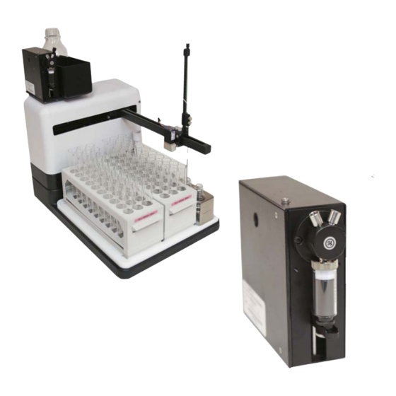
Summary of Contents for Teledyne AutoInjector Module
- Page 1 Automation Modules Installation and Operation Guide 69-5233-772 Copyright © 2016 Teledyne Technologies Incorporated. All rights reserved. Released: July 2016...
- Page 3 OSHA Guide 1910.1000. To reduce those levels to a safe exposure, Teledyne Isco recommends that you place the system in a laboratory hood designed for the purpose of ventilation. This hood should be constructed and operated in accordance with federal state and local regulations.
- Page 4 Automation Modules Installation and Operation Guide Safety Warnings DANGER DANGER – limited to the most extreme situations to identify an imminent hazard, which if not avoided, will result in death or serious injury. Hazard Symbols The equipment and this manual use symbols used to warn of hazards.
- Page 5 Automation Modules Installation and Operation Guide Safety Warnings For Additional Technical assistance for the Teledyne Isco Automation Modules Information can be obtained from: Teledyne Isco 4700 Superior St. Lincoln NE 68504 Phone: (800) 775-2965 or (402) 464-0231 Fax: (402) 465-3001...
- Page 6 Automation Modules Installation and Operation Guide Safety Warnings...
-
Page 7: Table Of Contents
A.1 AutoInjector Module Specifications ........ - Page 8 Automation Modules Table of Contents...
-
Page 9: Section 1 Introduction
Automation Modules Section 1 Introduction 1.1 Overview The AutoInjector Module, AutoSampler Module, and Column Selector Module allow you to increase the productivity of the ® CombiFlash EZ Prep by automating a number of tasks involved with high-performance liquid chromatography (HPLC). These ®... - Page 10 Automation Modules Section 1 Introduction...
-
Page 11: Section 2 The Autoinjector Module
CombiFlash EZ Prep software must be version 3.1.0 or higher to support the automation capabilities. Note If the AutoInjector Module is used in conjunction with the Col- umn Selector Module, the standard prep column mount can be removed to keep the overall system width minimized. In... - Page 12 Figure 2-3 Removing the waste line from the EZ Prep inject valve 5. Install the AutoInjector Module by placing it on top of the prep column mount and pressing downwards. The tab on the bottom of the AutoInjector Module will snap into the...
- Page 13 Section 2 The AutoInjector Module Figure 2-4 AutoInjector Module attached to the EZ Prep column mount 6. Connect the USB cable from the AutoInjector Module to the USB port on the rear of the EZ Prep. If you have a CombiFlash Rf+ PurIon...
- Page 14 Automation Section 2 The AutoInjector Module Figure 2-5 Waste tubing fitting attached to the EZ Prep inject valve 11. Turn the plastic ferrule until it is attached hand tight to the valve. 12. Turn the steel fitting turn tighter. 13. Remove the plastic ferrule while leaving the fitting attached.
- Page 15 15. Connect the opposite end of this tubing to the left port of the AutoInjector Module. Figure 2-8 Connection of the waste tubing from the EZ Prep inject valve to the left AutoInjector Module port 16. Connect the supplied waste line ( 60-5234-654) to the right port of the AutoInjector Module.
- Page 16 Figure 2-9 Waste line connected to the right AutoInjector Module port 17. Connect the check valve removed in Step 4 to the waste line from the AutoInjector Module. Ensure that the arrow on the check valve points away from the AutoInjector Mod- ule as shown in Figure 2-10.
- Page 17 Automation Section 2 The AutoInjector Module Figure 2-11 Sample tube fitting attached to the EZ Prep inject valve 21. Turn the plastic ferrule until it is attached hand tight to the valve. 22. Turn the steel fitting turn tighter. 23. Remove the plastic ferrule while leaving the fitting attached.
-
Page 18: Autoinjector Module Operation
This warning can be ignored at the discretion of the user. 2.2 AutoInjector Module Operation 2.2.1 Setup Before using the AutoInjector Module for the first time, the EZ Prep should be configured for the proper injection loop volume. 1. Begin by going to T HPLC. OOLS ONFIG 2. -
Page 19: Operation
This warning can be ignored at the discretion of the user. 2.2.2 Operation To use the AutoInjector Module, follow the steps below: 1. Place the sample probe into your sample container. 2. Press P to start a separation as you would for an indi- vidual separation. - Page 20 Automation Section 2 The AutoInjector Module Figure 2-15 Selecting for multiple injections 5. In the dialogue box, enter the total sample volume and the number of injections as show in Figure 2-16. Figure 2-16 Selecting the sample volume and number of...
- Page 21 Automation Section 2 The AutoInjector Module PeakTrak will divide the total volume by the number of injec- tions to determine the injection volume for each separation. If this volume exceeds 50% of the loop volume, a warning message will appear recommending a change in the parameters. This message can be ignored at the discretion of the user.
- Page 22 Automation Section 2 The AutoInjector Module 10. The remaining injections can be immediately viewed by pressing the left or right arrows at the lower left and right of the file viewer screen (Figure 2-17). This function can also be used to immediately view files before or after the currently viewed file even if they are not part of the same injection sequence.
-
Page 23: Section 3 The Autosampler Module
EZ Prep. You will be prompted to place the AutoSam- pler Module on the right side of the EZ Prep in 3.1.2 Estab- lishing Connections. The AutoSampler Module includes the AutoInjector Module to perform its automated functions. To install the AutoSampler Module, follow the steps below: 3.1.1 Installing the... - Page 24 Automation Section 3 The AutoSampler Module Figure 3-2 AutoSampler Module wash station with tubing attached 2. Route the bottom section of tubing (labeled “3”) from the rinse station to the matching fitting (labeled “3”) at the bottom of the AutoSampler Module’s peristaltic pump. Be sure to select the fitting furthest from the back of the mod- ule.
- Page 25 Automation Section 3 The AutoSampler Module Figure 3-4 Routing the top section of wash station tubing 4. Assemble two wash solution input tubing sections by inserting the smaller piece of tubing directly into the larger piece of tubing. Figure 3-5 Sample input tubing section assembly 5.
- Page 26 Automation Section 3 The AutoSampler Module Note The smaller piece of tubing from Step 4 is resistant to chemical corrosion, but the larger piece is not. When inserting the tubing into the wash solution, be sure only the smaller piece of tubing is resting inside the solution.
- Page 27 Automation Section 3 The AutoSampler Module Figure 3-7 Z-Drive mounted on the Y-axis carriage 9. Secure the Z-Drive to the carriage using the two thumb- screws. Tighten the thumbscrews with your fingers. Figure 3-8 Z-Drive secured to the Y-axis carriage 10.
- Page 28 Z-Drive, and then tighten the probe clamps with your hands. Mounting the AutoInjector 14. Install the AutoInjector Module onto the AutoSampler Module Module by removing the upper-left and lower-right mount- ing screws on the AutoSampler Module back panel.
- Page 29 Section 3 The AutoSampler Module Figure 3-11 AutoSampler Module back panel with AutoInjector Module mounting screws removed 15. Place the AutoInjector Module on top of the AutoSampler Module and fasten them together with the mounting screws removed in Step 14.
- Page 30 Automation Section 3 The AutoSampler Module Figure 3-13 Cables fed through the AutoInjector guide block Connecting the Z-Drive 17. Turn the rotor on the back of the AutoSampler Module clockwise as far as it will go. 18. Slide the green probe cable through the rear guide block and into the rotor until it completes the route.
- Page 31 Automation Section 3 The AutoSampler Module Note Be sure to route the probe cable through the proper receptacle on the rotor. The probe cable should follow the groove as shown in Figure 3-15. Figure 3-15 Illustration of the proper probe cable route through the rotor 19.
- Page 32 Automation Section 3 The AutoSampler Module Figure 3-16 Gap between the Z-axis slider and the cap at the top of the Z-Drive 21. Hold the cable flat against the rotor and secure the cable by tightening the thumbscrew on the rotor. The thumb- screw should be as tight as possible using just your fingers.
-
Page 33: Establishing Connections
Automation Section 3 The AutoSampler Module 3.1.2 Establishing To establish the necessary connections, follow the steps below: Connections 1. Place the AutoSampler Module on the right side of the EZ Prep. 2. Remove the Luer fitting from the EZ Prep inject valve. Figure 3-18 Removing the default EZ Prep injector port 3. - Page 34 Automation Section 3 The AutoSampler Module 8. Remove the plastic ferrule while leaving the fitting attached. Figure 3-20 Sample probe tube fitting with the plastic ferrule removed 9. Attach the supplied sample probe tubing from this package to the secured fitting by screwing the new plastic ferrule into the fitting.
- Page 35 Automation Section 3 The AutoSampler Module Figure 3-22 Sample probe tubing secured to the EZ Prep Note The tubing bracket should be affixed to the EZ Prep so that the probe tubing threads vertically through the bracket. This ensures that the probe tubing will not be obstructed by other tubing.
- Page 36 Automation Section 3 The AutoSampler Module Figure 3-24 Diverter Valve Waste port with AutoSampler Module tubing connection 13. Connect the remaining tubing from the AutoSampler to the tubing removed in Step 11. Figure 3-25 Connecting AutoSampler waste tubing to EZ Prep waste tubing 14.
- Page 37 Automation Section 3 The AutoSampler Module 15. Connect the provided USB cable from the USB-A port on the back of the EZ Prep to the USB-B port on the back of the AutoSampler Module. Figure 3-27 EZ Prep USB-A connection Figure 3-28 AutoSampler Module USB-B connection 16.
- Page 38 Automation Section 3 The AutoSampler Module Figure 3-30 AutoSampler Module USB-A connection (center) 17. Connect the Z-Drive power cable to the port on the back of the AutoSampler Module. Figure 3-31 Z-Drive power cable connected to the AutoSampler Module 18. Locate the AutoSampler Module’s power supply bracket as show in Figure 3-32.
- Page 39 Automation Section 3 The AutoSampler Module Figure 3-32 AutoSampler Module power supply bracket 19. Remove the two bottom screws from the AutoSampler Module’s rotor. Figure 3-33 AutoSampler Module rotor before removing the bottom screws 3-17...
- Page 40 Automation Section 3 The AutoSampler Module Figure 3-34 AutoSampler Module rotor before after the bottom screws 20. Place the power supply bracket so the two holes in the bracket align with the two holes on the AutoSampler Mod- ule’s rotor. Secure the bracket with the provided screws. Figure 3-35 Power supply bracket secured to the AutoSampler Module 21.
-
Page 41: Installing The Autosampler Module With The Column Selector Module
Automation Section 3 The AutoSampler Module Figure 3-36 Inserting the power supply into the power supply bracket 22. Plug the power supply into the respective port and then connect the power supply to a suitable power source. Figure 3-37 AutoSampler Module with power connection made 3.2 Installing the Using the AutoSampler Module in conjunction with the Column... -
Page 42: Autosampler Module Operation
Automation Section 3 The AutoSampler Module 3.3 AutoSampler Module The AutoSampler Module increases the fraction collection capacity of the CombiFlash EZ Prep by two racks. The RFID Operation capabilities of these additional racks are supported in the same way as the racks for the EZ Prep. When a rack is full, the system will automatically advance to the next available rack. -
Page 43: Operation
Automation Section 3 The AutoSampler Module The system software assumes the loop should only be 50% filled for maximum compound recovery. If the parameters entered for the individual injection exceed a 50% loop fill, a warning message will appear recommending a change in the parameters. This advice can be ignored at the discretion of the user. - Page 44 Automation Section 3 The AutoSampler Module Table 3-1 Queue Tab Columns Column Description Allows the user to remove a single row of an existing queue, clear all rows of the queue, or R Sample Name Allows the user to name each sam- ple.
- Page 45 Automation Section 3 The AutoSampler Module Table 3-1 Queue Tab Columns Number of Injections Used in conjunction with the S AMPLE column to determine the OLUMES size of each injection. Start Tube Allows the user to optimize rack usage by sharing the racks for multi- ple samples or placing each sam- ple’s result into individual racks to support multiple users.
- Page 46 Automation Section 3 The AutoSampler Module 3-24...
-
Page 47: Section 4 The Column Selector Module
Automation Section 4 The Column Selector Module 4.1 Column Selector Module Installation Note CombiFlash EZ Prep software must be version 3.1.0 or higher to support the automation capabilities. The Column Selector Module can be laid flat horizontally or stood on an edge vertically for installation. If you are installing the Column Selector Module horizontally, it is recommended that you install the columns prior to continuing with the Column Selector Module installation is recommended. - Page 48 Automation Section 4 The Column Selector Module 2. Use a 1/4” nut driver to remove the nut from the bottom section of the housing. Figure 4-2 Removing the bottom section housing nut 3. Use a 5/16” wrench to remove the nut located inside the EZ Prep column housing.
- Page 49 Automation Section 4 The Column Selector Module Figure 4-4 Location of the two EZ Prep mounting rail securing nuts Mounting the Column 1. Remove the three thumbscrews from the housing of the Selector Module Column Selector Module by hand. Figure 4-5 Location of the three Column Selector Module housing thumbscrews 2.
- Page 50 Automation Section 4 The Column Selector Module 3. When the Column Selector Module is set vertically along- side the EZ Prep, you will find two screws on the top of the module. Remove these two screws with a screwdriver. Figure 4-6 Two screws on top of the Column Selector Modules 4.
- Page 51 Automation Section 4 The Column Selector Module 6. Replace the cover plate and screw it into place. 7. Connect the Column Selector Module mounting rail attach- ment to the EZ Prep using the provided thumbscrew. Figure 4-8 Location of the Column Selector Module mounting rail attachment thumbscrew 8.
-
Page 52: Establishing Column Selector Module Connections
Automation Section 4 The Column Selector Module 4.1.2 Establishing Column 1. Connect the Column Selector Module to the EZ Prep using Selector Module the provided USB-to-RS232 cable. Connections Figure 4-10 Connected USB-to-RS232 cable 2. Remove the stainless steel tubing which connects the EZ Prep inject valve to the column inlet. - Page 53 Automation Section 4 The Column Selector Module 6. Connect the outlet port from the Column Selector Module outlet port to the outlet port on the EZ Prep using the pro- vided tubing and hardware. Figure 4-12 Proper outlet port tubing configuration Figure 4-13 Connected Column Selector Module outlet port tubing Note...
-
Page 54: Mounting The Autoinjector Module To The Column Selector Module
The Column Selector Module can be used in conjunction with the AutoInjector Module to AutoInjector Module. Begin by installing the Column Selector the Column Selector Module, and then install the AutoInjector Module using the steps Module below: 1. Remove the cover plate from the top of the Column Selec-... - Page 55 Automation Section 4 The Column Selector Module 2. Attach the AutoInjector Module to the top of the Column Selector Module using the two screws supplied with the module. Figure 4-15 Column Selector Module with attached AutoInjector Module 3. Remove the Luer fitting from the EZ Prep inject valve.
- Page 56 Figure 4-17 Removing the waste line from the EZ Prep inject valve 5. Install the AutoInjector Module by placing it on top of the prep column mount and pressing downwards. The tab on the bottom of the AutoInjector Module will snap into the receptacle on the top of the prep column mount.
- Page 57 Automation Section 4 The Column Selector Module in a location that minimizes the possibility of a chemical spill damaging the power supply. 8. Locate the supplied waste tubing and fitting package ( 60-5234-653). 9. Unscrew the attached plastic ferrule in this fitting package until the plastic ferrule is almost completely detached from the steel fitting.
- Page 58 Tighten the ferrule finger tight with the supplied tool. Ensure the tubing and fitting are snug in the EZ Prep inject valve. Figure 4-21 Waste fitting with tubing attached 15. Connect the opposite end of this tubing to the left port of the AutoInjector Module. 4-12...
- Page 59 Figure 4-23 Waste line connected to the right AutoInjector Module port 17. Connect the check valve removed in Step 4 to the waste line from the AutoInjector Module. Ensure that the arrow on the check valve points away from the AutoInjector Mod- ule as shown in Figure 4-24.
- Page 60 Automation Section 4 The Column Selector Module Figure 4-24 Check valve connected to the waste line of the AutoInjector Module 18. Locate the supplied sample probe tubing and fitting pack- age ( 60-5234-657). 19. Unscrew the attached plastic ferrule in this fitting package until the plastic ferrule is almost completely detached from the steel fitting.
- Page 61 Automation Section 4 The Column Selector Module Figure 4-26 Sample tube fitting with the plastic ferrule removed 24. Attach the supplied tubing from this package to the secured fitting by screwing the new plastic ferrule into the fitting. Tighten the ferrule finger tight with the supplied tool.
-
Page 62: Establishing Autoinjector Module Connections
Plug one end of the power cable into the Column Selector Module, and plug the other end into the AutoInjector Module. Then, plug the power cord into a suitable power supply. 4.2 Installing the Column... - Page 63 Automation Section 4 The Column Selector Module along with the diameter is used to estimate a column’s volume and suggest a default gradient duration. This parameter can also be overridden to decrease run time. 3. The debubbler automatically operates if one of the names of the solvents contains the words “water”, “H2O”, “was- ser”, “eau”, or “agua”.
- Page 64 Automation Section 4 The Column Selector Module 4-18...
-
Page 65: Appendix A Specifications
Automation Appendix A Specifications A.1 AutoInjector Module Specifications Dimensions 5.0 x 1.9 x 6.3 inches 12.7 x 4.8 x 16.0 cm Weight 4 lb 1.8 kg Temperature 20 - 40 °C Maximum Humidity 95% relative humidity Input Voltage 100 - 240 VAC; 50/60 Hz... -
Page 66: Autosampler Module Specifications
Automation Appendix A Specifications A.2 AutoSampler Module Specifications Dimensions 18.9 x 14.0 x 19.3 inches 48.0 x 35.6 x 49.0 cm Weight 31 lbs 14.1 kg Temperature 20 - 40 °C Maximum Humidity 95% relative humidity Input Voltage 100 - 240 VAC; 50/60 Hz Amps Disconnect Device Line cord... -
Page 67: Column Selector Module Specifications
Automation Appendix A Specifications A.3 Column Selector Module Specifications Dimensions (vertical setup) 14.5 x 4.6 x 16.1 inches 36.8 x 11.7 x 40.9 cm Dimensions (horizontal setup) 4.6 x 14.5 x 16.1inches 11.7 x 36.8 x 40.9 cm Weight 12.9 lb 5.9 kg Temperature 20 - 40 °C... - Page 68 Automation Appendix A Specifications...
- Page 69 Compliance Statements...
- Page 71 Name and amount of Hazardous Substances or Elements in the product Hazardous Substances or Elements Component Name (Pb) (Hg) (Cd) (Cr(VI)) (PBB) (PBDE) LCD Display (none on RF4X) Circuit boards Wiring Internal Cables Line Cord Stepper Motor Deuterium lamp Valve Body Name and amount of Hazardous Substances or Elements in the product O: Represent the concentration of the hazardous substance in this component’s any homogeneous pieces is lower than the ST/ standard limitation.
- Page 73 The warrantor is Teledyne Isco, 4700 Superior, Lincoln, NE 68504, U.S.A. *This warranty applies to the USA and countries where Teledyne Isco does not have an authorized dealer. Customers in countries outside the USA, where Teledyne Isco has an authorized dealer, should contact their Teledyne Isco dealer for warranty service.
Need help?
Do you have a question about the AutoInjector Module and is the answer not in the manual?
Questions and answers