
Related Manuals for Teledyne Foxy R1


Summary of Contents for Teledyne Foxy R1
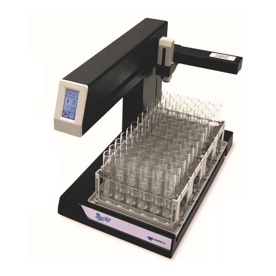
- Page 1 ® ® Foxy R1 and Foxy Fraction Collectors Foxy R1 Foxy R2 Part #69-2133-667 Copyright © 2008. All rights reserved, Teledyne Isco Revision K: April 2020...
- Page 3 Teledyne Isco recommends that you read this manual completely before placing the equipment in service. Although Teledyne Isco designs reliability into all equipment, there is always the possibility of a malfunction. This manual may help in diagnosing and repairing the malfunction.
-
Page 5: Table Of Contents
® ® Foxy R1 and Foxy Fraction Collectors Table of Contents Section 1 Introduction 1.1 Collection Schemes ..........1-2 1.2 Racks and Vessels . - Page 6 ® ® Foxy R1 and Foxy R2 Fraction Collectors Table of Contents 4.4 General Command Information ........4-1 4.4.1 Character Format .
- Page 7 1-1 Foxy R1 and Foxy R2 fraction collectors ....... . .
- Page 8 ® ® Foxy R1 and Foxy R2 Fraction Collectors Table of Contents List of Tables 1-3 Rear Panel Connectors ..........1-8 1-4 Ethernet Connector Pins .
- Page 9 OSHA Guide 1910.1000. To reduce those levels to a safe exposure, Teledyne Isco recommends that you place the system in a laboratory hood designed for the purpose of ventilation. This hood should be constructed and operated in accordance with federal state and local regulations.
- Page 10 ® ® Foxy R1 and Foxy R2 Fraction Collectors Safety This manual applies Hazard Severity Levels to the safety alerts, Hazard Severity Levels These three levels are described in the sample alerts below. CAUTION Cautions identify a potential hazard, which if not avoided, may result in minor or moderate injury.
- Page 11 ® ® Foxy R1 and Foxy R2 Fraction Collectors Safety The equipment and this manual use symbols used to warn of Hazard Symbols hazards. The symbols are explained below. Hazard Symbols Warnings and Cautions The exclamation point within the triangle is a warning sign alerting you of important instructions in the instrument’s technical reference manual.
- Page 12 ® ® Foxy R1 and Foxy R2 Fraction Collectors Safety...
- Page 13 R1 and Foxy Fraction Collectors Section 1 Introduction The Foxy R1 and R2 fraction collectors are liquid distribution instruments for indoor laboratory applications. The fraction col- lectors have the ability to divide the liquid into multiple col- lection vessels, switching vessels on time, drops, volume, peaks, or a combination of these parameters.
-
Page 14: Collection Schemes
® ® Foxy R1 and Foxy R2 Fraction Collectors Section 1 Introduction 1.1 Collection Schemes The fraction collector supports several types of collection schemes. Basic collection schemes collect uniform volumes (frac- tionation). These uniform modes for tube advances include: Drop Counting – The fraction collector counts the drops from the drop former. -
Page 15: Racks And Vessels
60-2137-062 Case of 40 glass 480 mL bottles for 60-5247-004 on the Foxy R2. On the Foxy R1, nine of these bottles may be placed directly on the drip tray—no rack is required. These racks are chemically resistant, made from stainless steel and polypropylene. -
Page 16: Features
All racks and funnels include RFID tags for automatic detection by the Foxy R2 fraction collector. 1.3 Features Figure 1-2 and Table 1-1 identify key features on the Foxy R1 and Foxy R2 fraction collectors. Table 1-1 Fraction collector features... -
Page 17: Fraction Collector Features
® ® Foxy R1 and Foxy R2 Fraction Collectors Section 1 Introduction Figure 1-2 Fraction collector features... -
Page 18: Technical Specifications
96-well microplates (R1 rack holds 2 plates; R2 rack holds 6 plates) 480 mL bottles Funnel racks for fractions larger than 480 mL Maximum Tube Height: Foxy R1: 160 mm Foxy R2: 196 mm Foxy R2 High Flow: 180 mm Maximum Flow Rate:... - Page 19 2000 meters Pollution Degree: Installation Category a. Teledyne Isco is continually improving its products therefore specifications are subject to change. b. No rack is required for R1 which holds 9 bottles on the drip tray. R2 re- quires a set of two racks which hold a total of 18 bottles.
-
Page 20: Rear Panel Connectors
® ® Foxy R1 and Foxy R2 Fraction Collectors Section 1 Introduction 1.5 Rear Panel Connectors The rear panel connectors are used to power the fraction collector and connect it to other devices. Table 1-3 Rear Panel Connectors Connectors Item Number Description Ethernet 1 Connector (See Table 1-4) Ethernet 2 Connector (Table 1-4) -
Page 21: Detector Connector Pins
® ® Foxy R1 and Foxy R2 Fraction Collectors Section 1 Introduction Table 1-5 Pump Connector Pins Connector Type Description Input Count: pump volume signal Output Pump pause: stops pump between tubes and at end of run Output Valve output: control signal for optional high flow diverter valve Common Circuit common... -
Page 22: Accessory Cable Specifications
® ® Foxy R1 and Foxy R2 Fraction Collectors Section 1 Introduction Table 1-7 RS-232 Serial Communication Connector Pins Connector Type Description Not used Output TxD RS-232 serial data out Input RxD RS-232 serial data in Reserved Common Circuit common Reserved Not used Not used... -
Page 23: Cable For Non-Isco Detectors
® ® Foxy R1 and Foxy R2 Fraction Collectors Section 1 Introduction Table 1-8 Non-Isco Pump Cable, P/N 69-2134-170 Connector Color Type Description Input Count: pump volume signal Output Pump pause: stops pump between tubes and at end of run Output Valve output: control signal for optional high flow diverter valve... - Page 24 ® ® Foxy R1 and Foxy R2 Fraction Collectors Section 1 Introduction 1-12...
-
Page 25: Section 2 Preparation For Use
® ® Foxy R1 and Foxy Fraction Collectors Section 2 Preparation for Use This section describes the setup procedures for the fraction col- lector and its optional accessories. Note Section 2.5 contains an Installation Qualification checklist. If required, sign off the checklist entries as you successfully complete the following sections. - Page 26 ® ® Foxy R1 and Foxy R2 Fraction Collectors Section 2 Preparation for Use Note To perform the preliminary checkout you will need to power the fraction collector. The fraction collector is shipped with either a North American IEC320C13 to NEMA 5-15P power cord or a European IEC320C13 to CEE7/VII power cord.
-
Page 27: Main Menu
® ® Foxy R1 and Foxy R2 Fraction Collectors Section 2 Preparation for Use Figure 2-2 Main menu Note Appendix A contains an icon glossary for complete descrip- tions of the icons used in the preliminary checkout procedure. 6. Touch the Folder icon twice to open a list of collection methods. -
Page 28: Time-Based Fractions Screen
® ® Foxy R1 and Foxy R2 Fraction Collectors Section 2 Preparation for Use Figure 2-4 Edit Method Settings screen 8. Touch the Time icon to display a screen at which you can modify the fraction collection based on time. 9. -
Page 29: Fluid Connections
® ® Foxy R1 and Foxy R2 Fraction Collectors Section 2 Preparation for Use 2.2 Fluid Connections There are three points for fluid connections on the fraction col- lector. Two are on the diverter valve — In and Waste. The third point is found on the drip tray which you can route to a waste container. -
Page 30: Tubing Preparation
® ® Foxy R1 and Foxy R2 Fraction Collectors Section 2 Preparation for Use 4. The accessory package includes a 10 ft length (3 m) of tub- ing. Cut a length of tubing to connect between the In port and the source. Note Cut the tubing with a tubing cutter to ensure that the end is cut cleanly and free from any deformation. -
Page 31: High Flow Diverter Valve Connections
® ® Foxy R1 and Foxy R2 Fraction Collectors Section 2 Preparation for Use 11. Connect the Waste line to the right-side port (when viewed from the back of the diverter valve). Route the other end to a waste collection container. The completed connections should appear as shown in Figure 2-8. -
Page 32: High Flow Diverter Valve Ports (Front View)
® ® Foxy R1 and Foxy R2 Fraction Collectors Section 2 Preparation for Use Waste (NO) (Common) Drop Former (NC) Figure 2-9 High flow diverter valve ports (front view) CAUTION Risk of fire or equipment damage caused by electrostatic dis- charge. -
Page 33: Drip Tray Drain Connection
® ® Foxy R1 and Foxy R2 Fraction Collectors Section 2 Preparation for Use CAUTION Plastic valve body damage possible. While swaging the tubing connections, always use two wrenches to prevent turning the metal fittings in the plastic valve body. Use one wrench to hold the inside nut to keep it from turning. -
Page 34: Rack Installation
Note Collection tube height must not exceed 150 mm for use with the Foxy R1 fraction collector. Tube height must not exceed 180 mm for use with the Foxy R2 fraction collector. 2. Ensure that the tops of the collection tubes are even. Tubes that do not drop fully into the rack might obstruct arm movement. - Page 35 ® ® Foxy R1 and Foxy R2 Fraction Collectors Section 2 Preparation for Use Guide Pins Ridges Figure 2-12 Rack guide pins and bottle location ridges CAUTION Risk of fire or explosion. Nonconductive, nonpolar liquids at lin- ear velocities greater than 40 cm/sec will develop an electro- static charge.
-
Page 36: Diverter Valve Adjustment
® ® Foxy R1 and Foxy R2 Fraction Collectors Section 2 Preparation for Use 2.4 Diverter Valve The height of the diverter valve should be adjusted to minimize the distance above the collection tubes. Adjustment This vertical adjustment should be performed whenever different types of racks or collection tubes are installed. -
Page 37: Installation Qualification Checklist
® ® Foxy R1 and Foxy R2 Fraction Collectors Section 2 Preparation for Use 2.5 Installation Table 5-1 Installation Qualification Checklist Qualification Installer Operator Checklist Step Description Initials Initials Preliminary Checkout 2.2.1/ Standard Diverter Valve 2.2.2 Connections or High Flow Diverter Valve Connections 2.2.3 Drip Tray Drain Connection... - Page 38 ® ® Foxy R1 and Foxy R2 Fraction Collectors Section 2 Preparation for Use 2-14...
-
Page 39: Section 3 Programming
® ® Foxy R1 and Foxy Fraction Collectors Section 3 Programming This section contains an overview of fraction collection pro- gramming via the touch screen interface. Programming via the touch screen supports basic collection applications where the fraction collector is one of several discrete components with or without a main controller. -
Page 40: Main Menu
® ® Foxy R1 and Foxy R2 Fraction Collectors Section 3 Programming 3.1 Main Menu All programming via the touch screen begins at the Main Menu (Figure 3-1). Configuration Tools Method Settings Collect in Tubes Divert to Waste Tube Position Tube Advance Play (start method) Standby... -
Page 41: Configuration Settings
® ® Foxy R1 and Foxy R2 Fraction Collectors Section 3 Programming 3.2 Configuration Settings Configuration settings define the overall fraction collector oper- ation. That is, these global settings are applicable regardless of whichever collection Method is selected. The fraction collector displays the Configuration menu (Figure 3-2) when you touch the Configuration Tools icon. - Page 42 ® ® Foxy R1 and Foxy R2 Fraction Collectors Section 3 Programming Note Rack 1 and Rack 2 The two-rack Foxy R2 fraction collector uses radio frequency identification (RFID) technology to automatically detect the rack types. The Rack options menu displays the detected rack types.
-
Page 43: Serial Settings
® ® Foxy R1 and Foxy R2 Fraction Collectors Section 3 Programming Calibrate The factory calibration positions the drop former over the col- lection tubes for all available rack types. Calibration is not nec- essary for most applications and commercially-available collection vessels. -
Page 44: Tcp/Ip Settings
® ® Foxy R1 and Foxy R2 Fraction Collectors Section 3 Programming The user-configurable parameter is the baud rate. To set the baud rate: 1. Touch the RS-232 Serial settings icon. 2. Select the desired baud rate from the list using the Up and Down Arrow buttons. -
Page 45: Inject Options Timing Diagram
® ® Foxy R1 and Foxy R2 Fraction Collectors Section 3 Programming Play/ Play Inject Samples … Pauses Pause Inject Signal Start of Restart Restart Restart Figure 3-4 Inject options timing diagram When first started (Figure 3-4, Start of Run) using one of the Inject options, the fraction collector pauses so that the sample can be injected, as indicated by the Play icon alternating with the Inject icon. - Page 46 ® ® Foxy R1 and Foxy R2 Fraction Collectors Section 3 Programming To set the time restart interval: 1. Touch the Arrow buttons to select a Timed option. A Folder icon appears at the top of the display. 2. Touch the Folder icon to open the Timed interval settings. 3.
-
Page 47: Pump Control Settings
® ® Foxy R1 and Foxy R2 Fraction Collectors Section 3 Programming One example of this tube-conserving option’s usefulness is to collect like eluate from multiple, identical samples while repeating the same liquid chromatography method. Because the peaks elute the same each time, greater volumes of pure com- pound can be collected in a tube. -
Page 48: Method Settings
® ® Foxy R1 and Foxy R2 Fraction Collectors Section 3 Programming 3.3 Method Settings Method settings define the fraction collector operation for a run. The fraction collector displays the Method Settings menu (Figure 3-7) when you touch the folder icon on Main menu. Use this menu to program the current method or select another of the eight stored methods. -
Page 49: Drop Counts
® ® Foxy R1 and Foxy R2 Fraction Collectors Section 3 Programming Method A Figure 3-9 Rename Method display 3.3.2 Drop Counts Drop counting creates fractions by advancing the drop former at a fixed number of drops. This option uses a photosensor device positioned just below the drop former. - Page 50 ® ® Foxy R1 and Foxy R2 Fraction Collectors Section 3 Programming Use this display to set the fraction volume—expressed as a number of drops, and the flow delay volume—expressed as time. 2. Ensure that the fraction volume setting is active as indi- cated by the Volume Select icon.
-
Page 51: Time Intervals
® ® Foxy R1 and Foxy R2 Fraction Collectors Section 3 Programming 3.3.3 Time Intervals Time intervals create fractions by advancing the drop former at a fixed time intervals. This option uses an internal clock. Note Time intervals can create widely varying collection tube vol- umes if the delivered flow rate is variable. -
Page 52: Volume
® ® Foxy R1 and Foxy R2 Fraction Collectors Section 3 Programming 3.3.4 Volume The Volume option creates fractions by advancing the drop former at a fixed number of pump counts. This option relies on a pump count signal delivered by an external device to pin 1 of the fraction collector’s Pump connector. -
Page 53: Threshold Detection
® ® Foxy R1 and Foxy R2 Fraction Collectors Section 3 Programming 5. Enter the Flow Delay volume as 1 to 999 counts using the arrow icons. The Up and Down Arrows increment or decre- ment the numbers, the Left and Right Arrows move the cursor position. - Page 54 ® ® Foxy R1 and Foxy R2 Fraction Collectors Section 3 Programming To program the fraction collector for Threshold peak detection: 1. Touch the Threshold Detection icon from the Method Set- tings menu to open the threshold menu (Figure 3-14). _10% Figure 3-14 Threshold Settings menu 2.
-
Page 55: Peak Width Detection
® ® Foxy R1 and Foxy R2 Fraction Collectors Section 3 Programming Note If you are using only threshold detection, select either the Union (OR) or Intersection (AND) option. Ensure that the peak width detection is set to None. 5. Touch the Enter icon to return to the Method Settings menu. - Page 56 ® ® Foxy R1 and Foxy R2 Fraction Collectors Section 3 Programming Figure 3-16 Peak Width Settings menu 2. Enter the average peak width using the Up and Down Arrow icons. The Up and Down Arrows scroll through the available Peak Width settings. Enter the average time duration of the expected peak, as measured at the baseline.
- Page 57 ® ® Foxy R1 and Foxy R2 Fraction Collectors Section 3 Programming using only peak width detection, select this Union option. Touch the icon to toggle the selection. Note If you are using only peak width detection, select either the Union (OR) or Intersection (AND) option.
-
Page 58: Time Windows
® ® Foxy R1 and Foxy R2 Fraction Collectors Section 3 Programming 3.3.7 Time Windows The Time Windows function allows the selection of up to four durations of the running time of which the fraction collector should enable collection. A time window may be used for several applications. - Page 59 ® ® Foxy R1 and Foxy R2 Fraction Collectors Section 3 Programming Figure 3-18 Time Windows Settings menu 2. Time Windows are either Off or combined with the selected peak detection where all conditions must be true. Touch the icon in the upper right corner to select the intersection (AND) option.
- Page 60 ® ® Foxy R1 and Foxy R2 Fraction Collectors Section 3 Programming 3-22...
-
Page 61: Section 4 Serial Command Control
® ® Foxy R1 and Foxy Fraction Collectors Section 4 Serial Command Control 4.1 Introduction The fraction collector has built-in RS-232 and Ethernet inter- faces that allow it to be remotely controlled. Remote control is typically done using a computer running a terminal program to send commands and receive data. -
Page 62: Command Syntax
® ® Foxy R1 and Foxy R2 Fraction Collectors Section 4 Serial Command Control 4.4.2 Command Syntax Commands consist of single keywords, possibly followed by an operand separated by a “=”, for example: BAUD or TUBE=42. Commands may be abbreviated to as few as three characters. Spaces are ignored. - Page 63 ® ® Foxy R1 and Foxy R2 Fraction Collectors Section 4 Serial Command Control Example: Command: CUE=1 Response: > CUE without an operand returns the current setting. Example: Command: Response: CUE=1 ECHO=n This command enables or disables echoing of char- acters received.
- Page 64 ® ® Foxy R1 and Foxy R2 Fraction Collectors Section 4 Serial Command Control LINEFEED This command enables (LINEFEED=1) or disables (LINEFEED=0) the sending of a linefeed character each time a carriage return is sent. LINEFEED=0 is set when unit is switched to OPERATE.
- Page 65 ® ® Foxy R1 and Foxy R2 Fraction Collectors Section 4 Serial Command Control RSVP This command instructs the unit to indicate completion of the preceding commands that take some time to perform. The response from the unit will be READY when the task is complete. For example, if you have sent RACK=1;RSVP, the unit moves the drop former over the rack and then responds: READY.
-
Page 66: Immediate Control Commands
Foxy R1 and R2 fraction collector. • DISPLAY • KEY=keys These commands were available for earlier fraction collector models. Do not use them with the Foxy R1 and R2 fraction col- lectors. 4.5.2 Immediate Control COLLECT The unit resumes collecting fractions after a Commands DRAIN command if this command is given during a run. - Page 67 ® ® Foxy R1 and Foxy R2 Fraction Collectors Section 4 Serial Command Control PUMP=n This command sets the pump controlled by the fraction collector on (PUMP=1) or off (PUMP=0). Example: Command: PUMP=1 Response: (none) A PUMP command without an operand returns the current setting.
- Page 68 ® ® Foxy R1 and Foxy R2 Fraction Collectors Section 4 Serial Command Control The fraction collector starts, continues, or restarts a run. Example: Command: Response: (none) R1DETECT or R2DETECT (Foxy R2 only) These commands query the two rack RFID readers that are connected to the circuit board.
- Page 69 ® ® Foxy R1 and Foxy R2 Fraction Collectors Section 4 Serial Command Control VALVE=n This command turns the valve on or off. Setting VALVE=0 will cause the flow to the drop former to be diverted to waste with a three-way valve. Setting VALVE=1 will allow flow to the drop former.
- Page 70 ® ® Foxy R1 and Foxy R2 Fraction Collectors Section 4 Serial Command Control Example: Command: DELAY Response: DELAY=102 FSIZE=n This command sets the fraction size for the current program. If FTYPE=1 (fraction by time), n=1 to 359999 seconds; if FTYPE=2 or 3 (fraction by drops or external counts), n=0 to 999999.
- Page 71 ® ® Foxy R1 and Foxy R2 Fraction Collectors Section 4 Serial Command Control NONPEAK=n This command sets the non-peak/window action of the current program. Choices are Collect (n=1), Divert (n=2), or Drain (n=3). Example: Command: NONPEAK=3 Response: (none) The NONPEAK command without an operand returns the current setting.
- Page 72 ® ® Foxy R1 and Foxy R2 Fraction Collectors Section 4 Serial Command Control RANGE=n This command sets the detector signal voltage range of the current program. The choices are: • n=1 1 Volt • n=2 100 mV • n=3 10 mV •...
- Page 73 ® ® Foxy R1 and Foxy R2 Fraction Collectors Section 4 Serial Command Control The RSTIME command without an operand returns the current setting. Example: Command: RSTIME Response: RSTIME=5000 R1LAST=n or R2LAST=n These commands set the last tube for Rack1 or Rack2. Choices are n=1 to n=maximum number of tubes for programmed rack type.
- Page 74 ® ® Foxy R1 and Foxy R2 Fraction Collectors Section 4 Serial Command Control THRESHOLD=n This command sets the peak threshold (n=0 [none] to 100)% of the current program. Example: Command: THRESHOLD=10 Response: (none) The THRESHOLD command without an operand returns the current setting.
- Page 75 ® ® Foxy R1 and Foxy R2 Fraction Collectors Section 4 Serial Command Control The WINDOW command without an operand returns the current setting. Example: Command: WINDOW Response: WINDOW=1 WSTART=n This command sets the window start time (n=0 to 359999 seconds) of the currently selected window. Example: Command: WSTART=36000...
-
Page 76: Programming Commands
The following serial commands are not supported by the fraction collector. • ESTATE=n • ETIME=n • ETYPE=n • EVENT=n • LIST • PTYPE These commands were available for earlier fraction collector models. Do not use them with the Foxy R1 and R2 fraction col- lectors. 4-16... -
Page 77: Problem Responses
® ® Foxy R1 and Foxy R2 Fraction Collectors Section 4 Serial Command Control 4.5.4 Problem Responses The fraction collector will respond with a PROBLEM=<type> message should the command fail. The following types may be reported. IMPROPER MODE The program values cannot be changed while a run is in progress. - Page 78 ® ® Foxy R1 and Foxy R2 Fraction Collectors Section 4 Serial Command Control 4-18...
-
Page 79: Section 5 Maintenance
® ® Foxy R1 and Foxy Fraction Collectors Section 5 Maintenance 5.1 Introduction The fraction collector is designed for years of use in typical labo- ratory applications. The recommended maintenance tasks pri- marily address the fluid path, drains, and the fraction collector exterior. -
Page 80: Collection Rack And Drip Tray Cleaning
® ® Foxy R1 and Foxy R2 Fraction Collectors Section 5 Maintenance Correct any deficiencies before returning the instrument to oper- ation. 5.2.2 Collection Rack and Drip Tray Cleaning WARNING Risk of fire or equipment damage. Dirty collection racks and drip tray might inhibit their conductive properties. -
Page 81: Drop Counter Cleaning
® ® Foxy R1 and Foxy R2 Fraction Collectors Section 5 Maintenance If problems occur frequently, consider pumping a cleaning fluid through the path as final step in each collection routine. 5.2.5 Drop Counter Cleaning The drop counter is a photosensor device at the outlet of the standard flow rate diverter valve. -
Page 82: Service
Customers outside of the US should contact their Teledyne Isco dealer for service support. Customers can find their regional dealer by visiting the Teledyne Isco Web site: http://www.isco.com/lccontact... -
Page 83: Appendix A Icon Glossary And Menu Charts
® ® Foxy R1 and Foxy Fraction Collectors Appendix A Icon Glossary and Menu Charts A.1 Touch Screen Icon Table A-1 describes the fraction collector display icons. Glossary Table A-1 Touch screen display icons Icon Description Select the Configuration Tools icon to configure the collection racks, communication settings, and injection overlay settings. - Page 84 ® ® Foxy R1 and Foxy R2 Fraction Collectors Appendix A Icon Glossary and Menu Charts Table A-1 Touch screen display icons (Continued) Icon Description Touch the Rack icon to open a screen from which you can select the rack type and collection pat- tern, and calibrate the drop former position.
- Page 85 ® ® Foxy R1 and Foxy R2 Fraction Collectors Appendix A Icon Glossary and Menu Charts Table A-1 Touch screen display icons (Continued) Icon Description Touch the Ethernet Port icon to open a screen from which you can configure TCP/IP communi- cation settings and view the MAC address.
- Page 86 ® ® Foxy R1 and Foxy R2 Fraction Collectors Appendix A Icon Glossary and Menu Charts Table A-1 Touch screen display icons (Continued) Icon Description Touch the Volume icon to collect fractions based on an external pump volume count. Touching this icon opens a screen from which you can set the fraction and delay volumes as a number of pump counts.
- Page 87 ® ® Foxy R1 and Foxy R2 Fraction Collectors Appendix A Icon Glossary and Menu Charts Table A-1 Touch screen display icons (Continued) Icon Description Touch the Peak Width Detection Options icons to toggle through the detection modes. The top icon indicates that peak width detection is OFF.
-
Page 88: Touch Screen Menu Flow Charts
® ® Foxy R1 and Foxy R2 Fraction Collectors Appendix A Icon Glossary and Menu Charts A.2 Touch Screen Menu Figures A-1 through A-4 illustrate the fraction collector menus. Flow Charts 1200 2400 4800 9600 19200 38400 57600 115200 None 99 h 1000 mV. -
Page 89: Configuration Settings, Continued
® ® Foxy R1 and Foxy R2 Fraction Collectors Appendix A Icon Glossary and Menu Charts none None 12mmx144 13mmx144 16mmx100 18mm x72 13mmx144 MiniVial 25mm x36 28mm x36 192.168. 1.202 IP MASK 255.255. 255. 00:17:8b 00:00:00 MASK SERIES: 255.255. 3870-010 192.168. - Page 90 ® ® Foxy R1 and Foxy R2 Fraction Collectors Appendix A Icon Glossary and Menu Charts To Fig. A-4 _10% Figure A-3 Programming displays for the current method...
- Page 91 ® ® Foxy R1 and Foxy R2 Fraction Collectors Appendix A Icon Glossary and Menu Charts From Fig. A-3 Method A Method A Method B 16mmTube Method D DefaultE DefaultF DefaultG DefaultH Figure A-4 Saved method recall and method name editing...
- Page 92 ® ® Foxy R1 and Foxy R2 Fraction Collectors Appendix A Icon Glossary and Menu Charts A-10...
- Page 93 ® ® Foxy R1 and Foxy Fraction Collectors Index connectors AC mains power, 1-8 AC power cord, 2-2 detector, 1-9 addresses, IP and MAC, 3-6 ethernet, 1-8 AND, combined peak detection, 3-16, 3-18, pump, 1-9 3-19 rear panel diagram, 1-8 applications, typical, 1-7 serial (RS232), 1-10 cables...
-
Page 94: Foxy R1 And Foxy R2 Fraction Collectors
Foxy® R1 and Foxy® R2 Fraction Collectors Index flow delays, 3-12 method flow rate, maximum, 1-6 selection menu, 2-3, 3-10 fluid path cleaning, 5-2 settings, 3-10 fluids, collect or divert, 3-16, 3-18 mode funnel racks, 1-4 computer icon, 3-1 local, 4-4 remote, 4-2, 4-4 glass sleeve, 5-3 next tube option, injection or timed restarts, 3-9... - Page 95 Foxy® R1 and Foxy® R2 Fraction Collectors Index renaming a method, 3-11 replacement parts, B-1 union (Venn diagram symbol), 3-19 restarts, 3-6 unpacking, 2-1 returns, 5-4 RFID, 2-10 defined, 1-1 Venn diagrams, 3-16, 3-18, 3-19 racks and funnels, 1-4 volume (pump count) RS232 serial general, 1-2 communications, 4-1...
- Page 96 Foxy® R1 and Foxy® R2 Fraction Collectors Index Index-4...
- Page 97 +1 (402) 464-0231 Facsimile: +1 (402) 465-3799 Equipment Type/Environment: Laboratory Equipment for Light Industrial/Commercial Environments Trade Name/Model No: Foxy R1, R2 Year of Issue: 2016 Standards to which Conformity is Declared: EN 61010-1 3 edition Safety Requirements for Electrical Equipment for...
- Page 99 RoHS Compliance Statements Name and amount of Hazardous Substances or Elements in the product Hazardous Substances or Elements Component Name (Pb) (Hg) (Cd) (Cr(VI)) (PBB) (PBDE) Circuit Board LCD Display Wiring Internal Cables Line Cord Transformer DC Motor Keypad Name and amount of Hazardous Substances or Elements in the product O: Represent the concentration of the hazardous substance in this component’s any homogeneous pieces is lower than the ST/ standard limitation.
- Page 101 FOR WARRANTY: Please consult our website at www.teledyneisco.com to download a digital copy of the Warranty for your Foxy Fraction Collector. Before returning any instrument for repair, please call, fax, or e-mail the Teledyne Isco Service Department for instructions. Many problems can often be diagnosed and corrected over the phone, or by e-mail, without returning the instrument to the factory.
Need help?
Do you have a question about the Foxy R1 and is the answer not in the manual?
Questions and answers