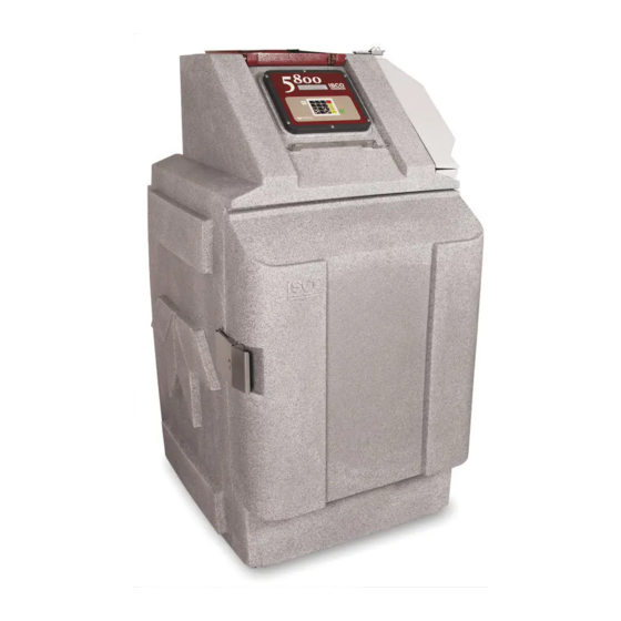
Teledyne 5800 Instruction Sheet
Hide thumbs
Also See for 5800:
- Installation and operation manual (153 pages) ,
- Removal and replacement (9 pages) ,
- Instruction sheet (7 pages)
Table of Contents
Advertisement
Quick Links
Pressurized Line Liquid
Sampling System
For the Isco 5800 Refrigerated Sampler
Overview
The pressurized line sampling system for the Isco
5800 sampler consists of the sampler, a relay alarm box,
a 3-way actuated ball valve, an aluminum mounting
plate, and, if pressures will be in excess of 15 psi, a pres-
sure reduction valve. The system supports sampling
from pipes with pressures up to 300 psi. This is also
compatible with the 4700 Sampler.
Operation
A normal sample routine consists of the sampler
pumping first in reverse (pre-purge), then forward
(bottle fill), and reverse again (post-purge).
When the sampler runs forward, it sends a signal to
the relay alarm box (see the instructions under
Programming to activate this function). The alarm box
alerts the 3-way valve to allow pumping of the sample
liquid. During pre-purge and post-purge, the valve
causes the remaining liquid between itself and the sam-
pler to be discharged through the third port into the
user-supplied drain.
Pressures exceeding 15 psi must be reduced prior to
reaching the 3-way valve to maintain accurate sample
volumes and avoid damage to the system. Isco offers a
stainless-steel pressure reduction valve with
fittings.
Site Requirements
The discharge drain must be routed to a point at or
near zero pressure for complete purging and prevention
of cross-contamination between samples.
The Isco pressure reduction valve is not recom-
mended for sample sources containing solids, or with
viscosities higher than that of no. 2 oil. The user is
responsible for any pre-filtering required.
The Isco relay alarm box is an essential component
of this system. It is equipped with specific hardware, cir-
cuitry, and weatherproof enclosure not feasibly
duplicated in the field.
The system must be positioned near a mains outlet
that is easily accessible, so that power can be quickly
removed in the event of an emergency.
The line cord is the only disconnect device. Mains
power is applied to the system continually.
WARNING
If this equipment is used in a manner not specified
in the instructions, safety may be compromised.
Setup and Installation
Programming
When enabled, a software option causes the sampler
to delay the bottle fill and post-purge pumping steps by
10 seconds to allow the 3-way valve to fully open. This
option must be enabled for proper filling and purging
during pressurized sampling.
To enable the pump valve option:
1. Turn the sampler controller on. From the main
menu, select CONFIGURE.
2. At SELECT OPTION, arrow to OUTPUT PINS and
select.
3. Under SET OUTPUT 1, arrow to 3-WAY VALVE
CONTROL and select.
1
/
" NPT
2
4. Continue programming output pins as needed,
and then select EXIT CONFIGURATION.
Instruction Sheet #60-5304-479
Revision B, December 5, 2012
PROGRAM
VIEW LOG
SELECT OPTION (<- ->)
OUTPUT PINS
SET OUTPUT 1: (<- ->)
3-WAY VALVE CONTROL
SELECT OPTION (<- ->)
EXIT CONFIGURATION
CONFIGURE
Advertisement
Table of Contents

Summary of Contents for Teledyne 5800
- Page 1 Overview The pressurized line sampling system for the Isco Setup and Installation 5800 sampler consists of the sampler, a relay alarm box, a 3-way actuated ball valve, an aluminum mounting Programming plate, and, if pressures will be in excess of 15 psi, a pres- When enabled, a software option causes the sampler sure reduction valve.
- Page 2 Revision B, December 5, 2012 #10 Mounting 3-way ball valve hardware assembly Mounting plate Liquid source Relay alarm box (10-300 PSI) Accessory con- nector (see sampler manual) To drain Pressure reduction valve 10ft sampler 6ft line cord connect cable Output to sampler Figure 1: System Components Ensure that the sampler outlet is positioned higher than its connection to the 3-way valve to ensure com-...
- Page 3 P.O. Box 82531, Lincoln, Nebraska, 68501 USA Toll-free: (800) 775-2965 • Phone: (402) 464-0231 • Fax: (402) 465-3001 E-mail: IscoService@teledyne.com Teledyne Isco is continually improving its products and reserves the right to change product specifications, replacement parts, schematics, and instructions without notice.
- Page 4 DECLARATION OF CONFORMITY Application of Council Directive: 2004/108/EC -The EMC Directive 2002/96/EC – The WEEE Directive 2006/95/EC– The Low Voltage Directive Manufacturer's Name: Teledyne Isco, Inc. Manufacturer's Address: 4700 Superior Lincoln, Nebraska 68504-1398 USA P.O. Box 82531, Lincoln, NE 68501-2531 Phone:...


Need help?
Do you have a question about the 5800 and is the answer not in the manual?
Questions and answers