Table of Contents
Advertisement
Quick Links
CombiFlash
NextGen
®
Installation and Operation Guide
Part Number 69-5253-032
© 2020 Teledyne Technologies Incorporated. All rights reserved.
Rev. F, December 2023
Software version 5.0.89
Use and Disclosure of Data: Information contained herein is classified as EAR99 under the U.S. Export Administration Regulations.
Export, reexport or diversion contrary to U.S. law is prohibited.
Advertisement
Table of Contents

Related Manuals for Teledyne CombiFlash NextGen


Summary of Contents for Teledyne CombiFlash NextGen
- Page 1 ® Installation and Operation Guide Part Number 69-5253-032 © 2020 Teledyne Technologies Incorporated. All rights reserved. Rev. F, December 2023 Software version 5.0.89 Use and Disclosure of Data: Information contained herein is classified as EAR99 under the U.S. Export Administration Regulations.
- Page 3 Safety hazards and preventive measures must be fully understood. Refer to Section1.6 Safety in this Operation Guide for general warnings about safety that pertain to the CombiFlash NextGen system. While specific hazards may vary according to location and appli- cation, heed the following general warning:...
- Page 4 CombiFlash NextGen Installation and Operation Guide Safety Warnings Hazard Severity Levels This manual applies Hazard Severity Levels to the safety alerts. These three levels are described in the sample alerts below. CAUTION Cautions identify a potential hazard, which if not avoided, may result in minor or moderate injury.
- Page 5 CombiFlash NextGen Installation and Operation Guide Safety Warnings Hazard Symbols The equipment and this manual use symbols used to warn of hazards. The symbols are explained in the table below. Hazard Symbols Warnings and Cautions The exclamation point within the triangle is a warning sign alerting you of important instructions in the instrument’s technical reference manual.
- Page 6 CombiFlash NextGen Installation and Operation Guide Safety Warnings For Additional Technical assistance for the Teledyne ISCO CombiFlash Information NextGen can be obtained from: Teledyne ISCO 4700 Superior St. Lincoln NE 68504 Phone: (800) 775-2965 or (402) 853-5340 Fax: (402) 465-3001 E-mail: IscoService@teledyne.com...
-
Page 7: Table Of Contents
2.5 External Gas ............2-5 2.5.1 CombiFlash NextGen Equipped with Optional ELSD ....2-5 2.6 Connect and Route Drain Lines . - Page 8 CombiFlash NextGen Systems Table of Contents 3.2 Loading a RediSep Column ......... . . 3-2 3.3 Starting a Separation .
- Page 9 CombiFlash NextGen Systems Table of Contents 5.7.8 PurIon Cone Cleaning ......... 5-13 5.7.9 Capillary Inlet Cone Removal .
- Page 10 CombiFlash NextGen Systems Table of Contents...
-
Page 11: Section 1 Introduction
Windows and iOS operating systems • Basic user operation • Software overview 1.2 Product Overview The Teledyne ISCO CombiFlash NextGen flash chromatography system gives you high-productivity automation, programmable gradients, UV detection and peak separation, and automatic detection of columns and collection tube racks (system dependent). - Page 12 PDA UV detector with optional UV-vis, Evaporative Light Scat- tering Detection (ELSD) or PurIon Mass Spectrometer detection. Figure 1-1 CombiFlash NextGen 100 with 12 inch display, 1-100 mL/min, 150 psi (without solid load injection valve) EAR99 Technology Technology Subject to Restrictions Contained on the Cover Page...
- Page 13 • a choice of either a 12 inch or 15 inch touchscreen display Figure 1-2 CombiFlash NextGen 300 system with 12-inch display, 1–300 mL/min, 300 psi (with automatic injection valve) EAR99 Technology Technology Subject to Restrictions Contained on the Cover Page...
- Page 14 ELSD or PurIon Mass Spectrometer detection, • a choice of either a 12 inch or 15 inch touchscreen display. Figure 1-3 CombiFlash NextGen 300+ system with 15-inch display, 1–300 mL/min, 300 psi EAR99 Technology Technology Subject to Restrictions Contained on the Cover Page...
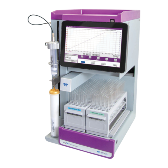
- Page 15 Applications include purification of organic compounds for drug discovery, as well as research in agrochemicals, petrochemicals, natural products, polymers, and catalysts. Figure 1-4 CombiFlash NextGen 300+ with 15-inch display and PurIon EAR99 Technology Technology Subject to Restrictions Contained on the Cover Page...
-
Page 16: Operating Overview
CombiFlash NextGen Systems Section 1 Introduction 1.3 Operating Overview The CombiFlash NextGen system is equipped with a capacitive 1.3.1 System Control touch screen display for local control. Possibilities The system also supports TCP/IP communication to allow direct or network control of the system by a computer using a modern web browser such as Microsoft Edge, Google Chrome, or Mozilla Firefox. - Page 17 Section 1.6.5. Maximum pressure limit is also set at 200 psi for methods using a solid-load cartridge. Solvent supply containers can be located up to 0.9 m below CombiFlash NextGen systems except when using dichloromethane. Dichloromethane containers must be at the same level as the NextGen or above.
- Page 18 All specifications are subject to change. b. CombiFlash NextGen 300 or 300+ systems with PurIon detector are not be capable of operation at flow rates greater than 200 ml/min with some solvent systems due to excessive back pressure in the flow splitter valve.
-
Page 19: Controls, Indicators, And Features Of Combiflash Nextgen Systems
Features of CombiFlash NextGen Systems Figure 1-5 CombiFlash NextGen features (front) 1. Touch Panel LCD display – Large 12 or 15 inch diagonal High Definition display for system monitoring and control. 2. USB Port – Convenient, front panel port that accepts USB flash memory drive. - Page 20 12. Vapor Enclosure – Encloses the fraction collection area, allowing for hook up to external exhaust for use outside of hood (optional). Figure 1-6 CombiFlash NextGen features (sides) 1-10 EAR99 Technology Technology Subject to Restrictions Contained on the Cover Page...
- Page 21 CombiFlash NextGen Systems Section 1 Introduction Figure 1-7 CombiFlash NextGen features (back) 13. Upper Drain Tube – Liquids spilled on the top shelf are carried away through this tube to a user-supplied container. 14. Ethernet Port – An 8P8C jack for a network connection using a standard CAT5 cable, or for a direct connection to a computer.
- Page 22 25. Cooling Fan – (ELSD equipped models only) Cools the internal ELSD components. Figure 1-8 CombiFlash NextGen ELSD (back) and P-Trap Drain Vent Assembly 26. ELSD Exhaust Port – (ELSD equipped models only) Vents the carrier gas and vaporized solvents.
-
Page 23: Safety
CombiFlash NextGen Systems Section 1 Introduction CAUTION Discontinue use of the CombiFlash NextGen system if liquid is present at the Pump Drain. Contact Teledyne ISCO technical service for assistance with correcting the leak. 1.6 Safety Before installing, operating, or maintaining this equipment, it is imperative that all hazards and preventive measures are fully understood. -
Page 24: Hazard Severity Levels
CombiFlash NextGen Systems Section 1 Introduction This manual applies Hazard Severity Levels to the safety alerts. 1.6.1 Hazard Severity Levels These three levels are described in the sample alerts below. CAUTION Cautions identify a potential hazard which, if not avoided, may result in minor or moderate injury. -
Page 25: Additional Information
Punto del machacamiento. Sus dedos o manos seriusly serán dañados si usted los coloca entre las piezas móviles cerca de estos símbolos. Technical assistance for the CombiFlash NextGen system can be 1.6.3 Additional obtained from: Information Teledyne ISCO 4700 Superior St. -
Page 26: Pressure Limits
The encoded pressure limit is half the average burst pressure for the column size in use. This infor- mation is read by the CombiFlash NextGen system (if equipped with the RFID option) and used to establish the maximum oper- ating conditions for the separation. -
Page 27: Overpressure Conditions
CombiFlash NextGen Systems Section 1 Introduction Note The pressure limit is 200 psi, if using the solid-load car- tridge loading method. If the pressure transducers are properly functioning and an over- 1.6.6 Overpressure pressure condition is detected, the system will respond Conditions depending on the severity of overpressure. - Page 28 CombiFlash NextGen Systems Section 1 Introduction 1-18 EAR99 Technology Technology Subject to Restrictions Contained on the Cover Page...
-
Page 29: Section 2 Preparation
2.1 Unpacking the System The CombiFlash NextGen system is shipped in a single carton. Carefully unpack the shipment and inspect the contents. WARNING The system is heavy. Use a two-person lift to prevent injury. - Page 30 CombiFlash NextGen Systems Section 2 Preparation Compare the contents of the boxes with the enclosed packing slips. If there are any shortages, contact Teledyne ISCO immedi- ately. The fraction collector arm is stowed to prevent damage during shipping. Perform the following steps to release the arm after shipment.
-
Page 31: Instrument Location
CombiFlash NextGen Systems Section 2 Preparation 2.2 Instrument Location The CombiFlash NextGen systems have a relatively small foot- print, requiring about 1550 square centimeters (240 in ) of level bench space. Ensure that the system has at least 3 cm (1.25 in) of air space behind it for ventilation. - Page 32 The CombiFlash NextGen instrument comes with the solvent inlet lines and waste lines pre-assembled to it. To install the unit: 1. Remove the 2 screws and shipping clamps identified in Figure 2-3.
-
Page 33: External Gas
Note Teledyne ISCO recommends >99% pure nitrogen from a source that can deliver 2.5 SLPM at 60 to 70 psi. EAR99 Technology Technology Subject to Restrictions Contained on the Cover Page... -
Page 34: Connect And Route Drain Lines
Improper draining may damage the instrument’s internal components. The CombiFlash NextGen system has drain tubes extending from its back panel. The tubes drain away any liquid spilled on the top shelf and the tray beneath the fraction collection racks. - Page 35 CombiFlash NextGen Systems Section 2 Preparation Vacuum or pressurized air applied to the outlet end of the drain tube must exist at the collection tray drain hole. Figure 2-5 Fraction collection tray drain hole Vacuum or pressurized air applied to the outlet end of the drain tube must exist at the top shelf drain hole.
- Page 36 CombiFlash NextGen Systems Section 2 Preparation Note It may be necessary to extend the drain tube. If so, splice the tubing with user-supplied tubing. The user-supplied tubing should have an inside diameter no smaller than the existing drain tubing, and must be compatible with the solvents used by the system.
- Page 37 CombiFlash NextGen Systems Section 2 Preparation P-trap drain vent assembly drain line Figure 2-7 Keep liquid level lower than the top of the system 7. Route the end of the P-trap drain tube to a suitable waste fluid collection container. Be aware that as the tubing is lowered, several mL of isopropyl alcohol will run out of the tubing.
-
Page 38: Vapor Enclosure (Optional)
CombiFlash NextGen Systems Section 2 Preparation CAUTION Discontinue use of the CombiFlash NextGen system if liquid is present at the Pump Drain. Contact Teledyne ISCO technical service for assistance with correcting the leak. 2.7 Vapor Enclosure 1. Secure the Vapor Enclosure with the three provided screws to the holes in the instrument (Figure 2-8). -
Page 39: Install Solid Load Cartridge Cap Ring Support And Slcc Storage Bracket (Optional)
CombiFlash NextGen Systems Section 2 Preparation 2.8 Install Solid Load 1. Secure the solid load cartridge cap (SLCC) storage bracket to the left side of the instrument with the screws provided Cartridge Cap Ring (Figure 2-10). Support and SLCC Storage Bracket... -
Page 40: Position The System
(Figure 1-5). Use care not to damage the connections, tubing, and cables while moving the system. CAUTION Ensure that the CombiFlash NextGen system has at least 3 cm (1.25 inch) of air space behind it for ventilation. Position the solvent and waste containers as necessary. -
Page 41: Install Collection Tube Racks
CombiFlash NextGen Systems Section 2 Preparation 2.10 Install Collection Tube Before beginning a run, you must load collection racks with tubes onto the system’s fraction collector tray. Racks Your system was shipped with two collection tube racks. The following tube rack sets are available: •... - Page 42 CombiFlash NextGen Systems Section 2 Preparation Figure 2-13 Loading test tubes 2. While holding the rack with the tube size label visible (Fig- ure 2-14), insert the racks into the system. Slide the rack in until it stops. You can feel it drop into its seated position when it is properly loaded.
-
Page 43: Powering On The System
CombiFlash NextGen Systems Section 2 Preparation 2.11 Powering on the System The system’s power switch is located on the lower right side panel, near the front of the instrument. 1. Switch the rear panel circuit breaker to O 2. Press the switch to turn the system on. The system will begin its startup routine, which includes self- diagnostics. -
Page 44: Solvents
CombiFlash NextGen Name (optional) – Use this option to 2.12.2 General Settings name your system. The name will appear in operational displays and separation reports. -
Page 45: Vapor Limit (If Equipped)
This allows us to supply columns as needed without need for inventory management at the customer’s site. 2.13 Vapor Limit (if The CombiFlash NextGen system has an internal vapor sensor that detects vapors present inside the system. This sensor mon- equipped) itors the system for premature pump seal failure or leaks of the internal plumbing connections. - Page 46 CombiFlash NextGen Systems Section 2 Preparation Table 2-1 Vapor Limits Percentage Sensitivity (relative to the LEL Setting of hexane) Medium High Medium and High sensitivity settings may result in false alarms (i.e., no internal leak in the system) when the ambient vapor level in the area is high.
-
Page 47: Set Default Tube Volumes
CombiFlash NextGen Systems Section 2 Preparation assumes any additional risk and has taken any additional steps to mitigate the increased risk of disabling or lowering the Vapor Limit sensitivity level. Click this button to set the default volume of the collection tubes. - Page 48 CombiFlash NextGen Systems Section 2 Preparation Note This option requires the system to be configured for network operation and a connection to a printer on the network. Net- work settings are discussed in Section 4. Do not select this option for these initial installation steps.
-
Page 49: User Management
CombiFlash NextGen Systems Section 2 Preparation zero. Before the final minute elapsed, more compound was detected, causing the system to extend the run for a final five minutes at the minimum %B. Enable rapid equilibration – Select this option to equilibrate the column at a higher flow rate. -
Page 50: Restart The System
CombiFlash NextGen Systems Section 2 Preparation Figure 2-20 User Management guide Some configuration settings do not take effect until the system is 2.13.4 Restart the System restarted. After completing the configuration, restart the system: 1. If the C window is not closed already, click... - Page 51 CombiFlash NextGen Systems Section 2 Preparation Figure 2-21 Auto Prime screen 2-23 EAR99 Technology Technology Subject to Restrictions Contained on the Cover Page...
- Page 52 CombiFlash NextGen Systems Section 2 Preparation 2. There are 4 solvent selection lists labeled from first solvent through fourth solvent, describing the order in which sol- vents will be pumped. The solvent choices for each list are those defined by the C window.
-
Page 53: System Verification
Section 2 Preparation 2.15 System Verification It is recommended that the system operation be verified using the CombiFlash Universal verification kit, Teledyne ISCO P/N 60-523-4317: • The instructions for Universal Verification Mix can be found in Instruction Sheet P/N 69-5233-870. -
Page 54: Installation Qualification Checklist
CombiFlash NextGen Systems Section 2 Preparation 2.16 Installation Table 2-1 may be completed to verify and document the instal- lation procedures contained in Section 2 of this guide: Qualification Checklist Table 2-2 Installation Qualification Checklist Installer Operator Step Section Description... -
Page 55: Section 3 Operation
Sample loading is covered in the included CombiFlash NextGen Quick Start Guide. If the sample is soluble in the starting mobile phase or a solvent 3.1.1 Liquid Sample strength that doesn’t significantly impact the separation, it can... -
Page 56: Loading A Redisep Column
3.3 Starting a Separation After completing the system installation steps, preparing the sample (See the CombiFlash NextGen Quick Start Guide for sample loading procedures), and inserting the column, you are ready to perform a run. The system will assume a default method based on the column size placed in the system. - Page 57 CombiFlash NextGen Systems Section 3 Operation The default settings include: • Pre-configured equilibration settings based upon column size and type. • Flow rate and separation length settings suitable for the column loaded. • A setting to collect all fluid in the fraction collector rack to ensure peaks without UV absorbance are collected.
- Page 58 CombiFlash NextGen Systems Section 3 Operation • Solid (Pause) – Select this option if you will place the sample into a solid sample load cartridge, but have not yet prepared the sample. (Column plan subscribers must also specify the cartridge type and size).
- Page 59 CombiFlash NextGen Systems Section 3 Operation Note If equipped with solvent level sensing and the waste level sensing tube is inserted correctly into the waste container, the systems will automatically suspend operation before an over- flow condition might exist. To prevent the run from being sus- pended before completing the run, ensure that the container will hold the expected waste volume.
-
Page 60: During The Separation
CombiFlash NextGen Systems Section 3 Operation • Select H for lightly loaded columns or samples with weak detection on the mass spectrometer. • For situations in-between, select M EDIUM Detection Ions – Enter up to 4 ions, or a range and up to 3 ions. -
Page 61: Bypassing The Solid Load Cartridge (Injection Valve Equipped Systems Only)
CombiFlash NextGen Systems Section 3 Operation Isocratic Hold – The I button holds the %B at SOCRATIC the current value while the system continues to operate. Note that holding the run extends the separation length. While in the isocratic hold state,... -
Page 62: Software Reference
CombiFlash NextGen Systems Section 3 Operation insufficient solvent. Note that isocratic holds and automatic run extensions during a run will increase the required solvent volume. The options available on the alert message will vary depending on when the condition occurs (before or during a run) and which method (measured level or estimated usage rate) indicated the condition. -
Page 63: Main Separation Screen
CombiFlash NextGen Systems Section 3 Operation The CombiFlash NextGen system comes configured as an open access system with all work done in a single common area. If so configured, the screen above is not shown at startup. In addition, it can be configured for multiple, individual users who can be assigned individual passwords. - Page 64 CombiFlash NextGen Systems Section 3 Operation top left of the screen allows for further method adjustment. • Z and P can be performed by using a two-finger pinch zoom (like many cell phones or tablets) or a two-finger pan. A single-finger touch or drag is inter- preted as a gradient edit, not a pan function.
-
Page 65: Method Editor Screen
CombiFlash NextGen Systems Section 3 Operation The M screen (Figure 3-4) allows control of less 3.5.2 Method Editor Screen ETHOD DITOR commonly used parameters that aren’t available on the M screen. EPARATION Figure 3-4 M screen ETHOD DITOR New (icon) – Opens a new method file using the default method 3.5.3 The Method Editor... -
Page 66: Method Editor Run Settings
CombiFlash NextGen Systems Section 3 Operation Time to CV or CV to Time – Toggles the units used for the hor- izontal axis during the separation from the configured units. • CV causes the E . and the R QUILIBR to be expressed in CV. -
Page 67: Edit Gradient Options
CombiFlash NextGen Systems Section 3 Operation • I – Entering a volume sends fluid to waste NITIAL ASTE before the first peak of interest, along with the antici- pated volume of fluid that will pass through the column before a compound of interest will elute. -
Page 68: Tube Volume
CombiFlash NextGen Systems Section 3 Operation • A - Collects all fluid during the time window. Detected peaks will still trigger tube advances. • N - Diverts all fluid to waste. Tube Volume – Sets the capacity for collected fluids. This 3.5.7 Tube Volume... - Page 69 CombiFlash NextGen Systems Section 3 Operation · Select the average peak width for your chromatog- raphy. Peak widths are measured at the baseline. The slope detector will detect peak widths ranging from about 0.2 to 2 times the peak width setting for a moderately sized peak.
- Page 70 CombiFlash NextGen Systems Section 3 Operation Figure 3-8 All Wavelength Detection Options window Detection Options (All Wavelength ) – The S IGNAL LOPE ASED HRESHOLD ONITOR ASELINE options on this window are similar as for UV ORRECTION and UV-vis detection (λ).
- Page 71 CombiFlash NextGen Systems Section 3 Operation solvents such as heptane, or reverse phase solvents such as water, methanol, or acetonitrile. • Spray Chamber Temperature – The default settings are 30 °C (normal phase default methods) and 15 °C (reverse phase).
- Page 72 CombiFlash NextGen Systems Section 3 Operation ratio remains steady while the concentration changes from the beginning to the end of the peak. During the duration of the peak, this constant value is displayed as a horizontal line. Now assume that there is a second compound eluting, only slightly shifted in time from the original compound.
-
Page 73: Manual Control
CombiFlash NextGen Systems Section 3 Operation > M 3.5.9 Manual Control OOLS ANUAL ONTROL Figure 3-11 Manual Control window Manual Control – This window allows control of the solvent pump, which allows the washing of individual flow paths. This is useful for troubleshooting and for cleaning flow paths of potential obstructions. -
Page 74: Results Screen
CombiFlash NextGen Systems Section 3 Operation 3.5.10 Results Screen Figure 3-12 Results screen At the end of a separation, the final chromatogram report is shown. At this point, the user can: print the report; customize the displayed report by adding multiple UV absorbance or mass... -
Page 75: Purion Operation
CombiFlash NextGen Systems Section 3 Operation Figure 3-14 Files screen The PurIon functions like another detector in the system. In 3.5.11 PurIon Operation addition, operation of the Mass Detector has been integrated into the PeakTrak control software. To use the PurIon, turn the PurIon power O (if not already on). - Page 76 CombiFlash NextGen Systems Section 3 Operation and enter your desired mass, it will compare INDER the 10 most intense ions with a list of common adducts or fragments to determine if your desired mass was detected as one of the peaks. If it was, you can select the peak for detection in your separation.
-
Page 77: The Focus Gradient Generator
CombiFlash NextGen Systems Section 3 Operation PurIon S and PurIon L systems will display a single temperature for both positive and negative ionization.) • Voltage (Current) – This displays a voltage setting (ESI probes) or current value (APCI probes). Lower values are used for more delicate compounds. -
Page 78: Focused Gradients For Flash Columns
CombiFlash NextGen Systems Section 3 Operation conditions for your separation. Focused gradients offer a quick way greatly improve resolution around the peaks of interest, decrease overall solvent usage, and generate less waste solvent. The Focus Gradient Generator is included in PeakTrak versions 5.1.7 and greater. - Page 79 CombiFlash NextGen Systems Section 3 Operation Figure 3-18 Detection Options window 4. When finished, close the D window and ETECTION PTIONS then the M to return to the Main Screen ETHOD DITOR showing the scouting gradient. 5. Press the S...
-
Page 80: Generating A Focused Gradient Method
CombiFlash NextGen Systems Section 3 Operation Figure 3-19 The end-of-run window Note Hint: pressing the Reset button closes the run, but you may calculate a focused gradient later by opening the file in the run viewer (F > O > select a .run file). -
Page 81: Focused Gradients From Analytical Hplc
CombiFlash NextGen Systems Section 3 Operation 4. Choose the S . Select either the amount OLID MOUNT of silica used in the solid load cartridge or choose L IQUID if you are doing a liquid injection. OADING 5. Press F . -
Page 82: Calculating The Focused Gradients
1. Run the scouting run on the analytical system 2. Note the retention time for the peak that needs to be puri- fied. 3. Load a column on the CombiFlash NextGen system. 4. From the M screen, select the C... - Page 83 CombiFlash NextGen Systems Section 3 Operation the same way and retention time data from scouting gradients will accurately calculate focused gradients. 3-29 EAR99 Technology Technology Subject to Restrictions Contained on the Cover Page...
- Page 84 CombiFlash NextGen Systems Section 3 Operation 3-30 EAR99 Technology Technology Subject to Restrictions Contained on the Cover Page...
-
Page 85: Section 4 Network Configuration
Connect the other end of the cable to your network access port. You should be able to connect to the CombiFlash NextGen system from a PC on the network (Section 4.1.1) and configure other network features such as network printing (Section 4.1.2) and network file saving (Section 4.1.3). -
Page 86: Network Pc Access
4.2 Direct Connection A direct connection supports communication between the CombiFlash NextGen system and a single PC that meets the rec- ommendations in Table 4-1. EAR99 Technology Technology Subject to Restrictions Contained on the Cover Page... - Page 87 CombiFlash NextGen Systems Section 4 Network Configuration EAR99 Technology Technology Subject to Restrictions Contained on the Cover Page...
- Page 88 CombiFlash NextGen Systems Section 4 Network Configuration EAR99 Technology Technology Subject to Restrictions Contained on the Cover Page...
-
Page 89: Section 5 Maintenance
As long as the AC mains power cord is connected, power is inside the unit. The mains power cord is the disconnect device. Position the CombiFlash NextGen system so that the power cord can be unplugged, or use a power strip where the plug can quickly be removed from the outlet in the event of an emergency. -
Page 90: Cleaning
CombiFlash NextGen Systems Section 5 Maintenance Every Run – Perform these tasks for each run: • Inspect Solid Load Cartridge Cap (Section 5.4.1). • Allow the separation run to finish with a high percentage of solvent B to flush residual compounds from the column, internal tubing, and flow cell (Section 5.5). -
Page 91: Inspection
CombiFlash NextGen Systems Section 5 Maintenance 5.4 Inspection WARNING Risk of fire or equipment damage. Faulty or worn seals, tubing, fittings, and drains may allow organic solvents to pool in unsafe areas, creating a potential for dangerous levels of flammable vapors. Improper draining may damage the instrument’s internal components. -
Page 92: Flow Cell Cleaning
CombiFlash NextGen Systems Section 5 Maintenance Vacuum or pressurized air applied to the outlet end of the drain tube must exist at the top self drain hole. Figure 5-2 Top shelf drain hole 5.5 Flow Cell Cleaning As a preventive measure, all default column methods finish the 5.5.1 Post Separation... -
Page 93: Quick Cleaning When Recommended
CombiFlash NextGen Systems Section 5 Maintenance Typically, chemists S and then T the run after the ERMINATE last compound elutes. This action skips the post-separation flush. If any of the above conditions appear, consider allowing some of the runs to continue through the flush, or run a high percentage of %B solvent through the system for a few minutes at the end of each day. - Page 94 CombiFlash NextGen Systems Section 5 Maintenance Figure 5-5 Raw lamp energy gauge • Red – Lamp energy is obstructed to a degree that the system might not reliably detect peaks. If you attempt to operate the system, peak collection will be forced to collect all.
-
Page 95: Monthly Flow Cell Cleaning
EQUIRED and monitor the Raw Lamp Energy. (Figure 5-5) If the lamp energy is in the green range, return the system to operation. If the lamp energy is red, contact Teledyne ISCO’s Technical Service department for assistance. 5.6 ELSD Maintenance Periodic cleaning of the spray chamber will keep the NextGen operating at maximum performance. - Page 96 CombiFlash NextGen Systems Section 5 Maintenance 4. Exit the Edit Method screen and accept the changes, then allow approximately 5 minutes for the chamber to reach the set temperature. Figure 5-7 Detection Options screens 5. Lift the P-trap drain tubing up to approximately case top level.
- Page 97 CombiFlash NextGen Systems Section 5 Maintenance Figure 5-8 Line filled with 40 ml of acetone 6. Place the open end of the P-trap drain line in a 100 mL (or greater) beaker. Figure 5-9 Draining the acetone into a 100 mL beaker 7.
-
Page 98: Purion Maintenance
CombiFlash NextGen Systems Section 5 Maintenance 12. Fill the P-trap with up to 40 mL of isopropyl alcohol as before, and drape the P-trap drain line of the top of the unit, then let it set for at least 20 minutes. -
Page 99: Esi And Apci Replacement Purion S And Purion L
CombiFlash NextGen Systems Section 5 Maintenance Figure 5-11 ESI and APCI removal from PurIon S and PurIon L 1. Carefully place the ion source housing on top of the base 5.7.2 ESI and APCI plate and line up with the rear electrical connection. Push... -
Page 100: Check Valve Cleaning
CombiFlash NextGen Systems Section 5 Maintenance PurIon source sprayer. The most common location for a plug is within the probe capillary. The occurrence of plugs can be reduced by using a 0.45 µ syringe filter when injecting samples for Method Development and Ionization Settings. To trouble- shoot an overpressure error, complete the following: •... -
Page 101: Replacing Check Valves
Even with the easy cleaning capability, Teledyne ISCO recommends keeping a spare capillary inlet cone assembly (Teledyne ISCO P/N 25-0000-085) to allow rapid replacement to minimize downtime while cleaning the plugged capillary. - Page 102 CombiFlash NextGen Systems Section 5 Maintenance 5. Remove the O-rings from the capillary inlet cone. 1. Remove the O-ring under the capillary base, then sonicate 5.7.10 Capillary Inlet Cone the capillary in a methonal:water (50:50) mixture for Cleaning 30 minutes (Figure 5-14).
- Page 103 CombiFlash NextGen Systems Section 5 Maintenance Table 5-1 Common PurIon Error Codes and Resolutions PurIon temperatures are stabilizing. The PurIon has several areas with heaters. The software has a set timer to allow temperatures to come up to oper- [r] seconds remain. (where [r] is a number) ating conditions.
- Page 104 CombiFlash NextGen Systems Section 5 Maintenance Table 5-2 General PurIon Troubleshooting Error/Symptom Solution • Verify nitrogen pressure. Nitrogen is required to nebulize the No signal on any mass, or very weak sample. signal • Check carrier solvent level, refill carrier solvent and re-prime the carrier solvent pump.
Need help?
Do you have a question about the CombiFlash NextGen and is the answer not in the manual?
Questions and answers