Canon imageRUNNER ADVANCE C2030 Service Manual
Hide thumbs
Also See for imageRUNNER ADVANCE C2030:
- Operating manual (49 pages) ,
- Service manual (24 pages) ,
- Manual (14 pages)
Table of Contents
Advertisement
Quick Links
Advertisement
Table of Contents
Troubleshooting

Related Manuals for Canon imageRUNNER ADVANCE C2030


Summary of Contents for Canon imageRUNNER ADVANCE C2030
- Page 1 December 23, 2014 Revision 9 imageRUNNER ADVANCE C2030/C2020 Service Manual Features/Specifications Process/Operation Consumable Parts and Cleaning Parts Parts Replacement and Cleaning Adjustment Troubleshooting Error Code Service Mode Installation Appendix...
- Page 2 This manual is copyrighted with all rights reserved. Under the copyright laws, this manual may changes in the contents of this manual over a long or short period, Canon will issue a new not be copied, reproduced or translated into another language, in whole or in part, without the edition of this manual.
- Page 3 Explanation of Symbols The following rules apply throughout this Service Manual: The following symbols are used throughout this Service Manual. Each chapter contains sections explaining the purpose of specific functions and the relationship between electrical and mechanical systems with reference to the timing of Symbols Explanation Symbols...
-
Page 4: Table Of Contents
Contents Safety Precautions Process/Operation Laser Safety --------------------------------------------------------------------0-2 Basic Configuration -----------------------------------------------------------2-2 Handling of Laser System --------------------------------------------------0-2 Functional Configuration --------------------------------------------------------- 2-2 Turn power switch ON -------------------------------------------------------0-3 Basic Sequence -------------------------------------------------------------------- 2-3 Safety of Toner -----------------------------------------------------------------0-3 Main Controller ----------------------------------------------------------------2-6 About Toner ------------------------------------------------------------------------- 0-3 Overview ----------------------------------------------------------------------------- 2-6 Toner on Clothing or Skin -------------------------------------------------------- 0-3 Controls -----------------------------------------------------------------------------2-14 Notes When Handling a Lithium Battery --------------------------------0-3... - Page 5 Checking the Operating Environment ------------------------------------- 2-112 Updater ---------------------------------------------------------------------- 2-191 Setting Up the Network -------------------------------------------------------- 2-115 Functional Overview ----------------------------------------------------------- 2-191 Login to SMS --------------------------------------------------------------------- 2-116 Limitations and Cautions ------------------------------------------------------ 2-195 Setting the method to login to SMS ---------------------------------------- 2-119 Preparation ----------------------------------------------------------------------- 2-196 Checking MEAP Application Management Page ----------------------- 2-122 System Management Operations ------------------------------------------- 2-202 Starting and Stopping a MEAP Application ------------------------------- 2-123...
- Page 6 Troubleshooting Removing the Hopper Unit (Bk) -----------------------------------------------4-67 Removing the Waste Toner Feed Assembly -------------------------------4-68 Initial Check --------------------------------------------------------------------6-2 Removing the Registration Patch Sensor ----------------------------------4-69 Initial check items list ------------------------------------------------------------- 6-2 Disassembly/Assembly - Fixing System - ----------------------------- 4-71 Test Print ------------------------------------------------------------------------6-3 Removing the Fixing Assembly ------------------------------------------------4-71 Overview ----------------------------------------------------------------------------- 6-3 Removing the Fixing Gear Assembly ----------------------------------------4-73 Steps to select the test print TYPE -------------------------------------------- 6-3...
- Page 7 Scope of Application ----------------------------------------------------------- 6-117 Display of Error Code/Alarm Code description ----------------------------- 8-4 Overview -------------------------------------------------------------------------- 6-117 COPIER > OPTION > BODY, Item Segmentation ------------------------- 8-4 Storing System Information -------------------------------------------------- 6-118 Security features ------------------------------------------------------------------- 8-5 Collecting System Information ----------------------------------------------- 6-120 Switching Screen (Level 1 < - > 2) -------------------------------------------- 8-6 Collecting Debug Log (USB memory device) ---------------------------- 6-120 Language switch ------------------------------------------------------------------- 8-6 DBG-LOG Screen -------------------------------------------------------------- 6-122...
- Page 8 Combination of the Options installing to the Right Side of the Check Items when Turning OFF the Main Power-------------------------9-43 Host Machine ----------------------------------------------------------------------- 9-4 Installation Outline Drawing ----------------------------------------------------9-43 Checking the Contents ------------------------------------------------------9-5 Installation procedure ------------------------------------------------------------9-44 Unpacking -----------------------------------------------------------------------9-7 Checking after Installation ------------------------------------------------------9-46 Installation Procedure --------------------------------------------------------9-9 Copy Tray-J1 ----------------------------------------------------------------- 9-47 Installing the Toner Container -------------------------------------------------- 9-9...
- Page 9 Checking the Contents ----------------------------------------------------------9-67 Points to note before installation -------------------------------------------- 9-107 Check Items when Turning OFF the Main Power-------------------------9-68 Checking the Contents [2.5inch/80GB HDD-E1]------------------------ 9-107 Installation Outline Drawing ----------------------------------------------------9-68 Check Items when Turning OFF the Main Power----------------------- 9-108 Installation Procedure ------------------------------------------------------------9-68 Installation Outline Drawing -------------------------------------------------- 9-108 Checking after Installation ------------------------------------------------------9-74 Installation Procedure ---------------------------------------------------------- 9-109...
- Page 10 0-10 Appendix Points to Note at Installation ------------------------------------------------- 9-141 Points to Note when Unpacking HDD Data Encryption & Service Tools ----------------------------------------------------------------- 10-2 Mirroring Kit ---------------------------------------------------------------------- 9-141 Special Tools -----------------------------------------------------------------------10-2 Checking the Contents [Removable HDD Kit-AE1] -------------------- 9-142 Solvents and Oils -----------------------------------------------------------------10-3 Checking the Contents [HDD Data Encryption Kit-C3] ---------------- 9-142 General Timing Chart ------------------------------------------------------ 10-4 Check Items when Turning OFF the Main Power----------------------- 9-143...
-
Page 11: Safety Precautions
Safety Precautions ■ Laser Safety ■ Handling of Laser System ■ Turn power switch ON ■ Safety of Toner ■ Notes When Handling a Lithium Battery ■ Notes Before it Works imageRUNNER ADVANCE Serving C2030/C2020 ■ Points to Note at Cleaning... -
Page 12: Laser Safety
Laser Safety Since radiation emitted inside the machine is completely confined within protective housings, external covers and interlock switches, the laser beam cannot escape from the machine during any phase of user operation. Therefore this machine is classified in Class 1 laser products that are regarded as safe during normal use according to International Standard IEC60825-1. -
Page 13: Turn Power Switch
Turn power switch ON Notes When Handling a Lithium Battery The machine is equipped with 2 power switches: main power switch and control panel power switch. CAUTION: The machine goes on when the main power switch is turned on (i.e., other than in low power RISK OF EXPLOSION IF BATTERY IS REPLACED BY AN INCORRECT TYPE. -
Page 14: Features/Specifications
Features/ Specifications ■ Product Lineup ■ Features ■ Specifications ■ Parts Name Features/Specifications Features/Specifications... -
Page 15: Host Machine
Features/Specifications Features/Specifications > Product Lineup > Host Machine > Model Type Product Lineup ■ Model Type C2030 C2025 C2020 Print speed 30ppm 25ppm 20ppm Host Machine (BW/Color) Positioning Cost-prioritized Standard-office model Target mode: iRC3380/2880 series, iRC3100 series For USA and Australia T-1-1 <HDD model>... -
Page 16: Options
Features/Specifications Features/Specifications > Product Lineup > Options > Pickup/Delivery/Image Reading System Options Options name Condition [1] imageRUNNER ADVANCE C2030/2025/2020 FLASH model ■ Pickup/Delivery/Image Reading System Options [2] imageRUNNER ADVANCE C2030/2025/2020 HDD model [3] imageRUNNER ADVANCE C2030/2025/2020 For Europe [4] DADF-AC1... - Page 17 Features/Specifications Features/Specifications > Product Lineup > Options > Function Expansion System Options ■ Function Expansion System Options name Condition [1] Utility Tray-A2 [2] Card Reader-C1/Copy Card Reader-F1 Copy Card Reader Attachment Kit-B2 [3] Super G3 FAX Board-AH1/AH2 1-line Fax Board is required. [4] Super G3 2nd Line FAX Board-AH1 1-line Fax Board is required.
-
Page 18: Features
Features/Specifications Features/Specifications > Features > Service Features > Applying New Connectors Features Service Features ■ Improved Upgrading Operability Product Features The options can be upgraded through the host machine. The version upgrading can be executed by any of the three methods; by using SST (Service Support Tool), via a USB memory using SST, and via Internet using CDS (Contents Display - Easy replacement with screw-less operation... - Page 19 Features/Specifications Features/Specifications > Features > Service Features > Realization of Breaker-less Machine ■ Realization of Breaker-less Machine - Conventional model To reduce costs, a breaker is discontinued. At the same time, the following two measures are Breaker AC Driver PCB executed to prevent leakage of electricity.
- Page 20 Features/Specifications Features/Specifications > Features > Service Features > Realization of Breaker-less Machine To replace major parts, a simple replacement procedure in which fixing screws do not have to be removed is introduced. This improved serviceability and enabled a user to execute replacement, which reduced a number of service calls.
-
Page 21: Specifications
Features/Specifications Features/Specifications > Specifications > Specifications Specifications Paper type (Cassette Thin paper (60 to 64g/m ), Plain paper 1 (65 to 82g/m ), Plain paper 2 (83 to 99g/m ), Plain paper 3 (100 to 105g/m ), Heavy paper 1 (106 to 120g/ ), Heavy paper 2 (121 to 163g/m ), Transparency, Envelope, Bond paper, Recycled paper, Pre-punched paper... -
Page 22: Weight And Size
Features/Specifications Features/Specifications > Specifications > Paper Type Weight and Size Paper Type Following shows the types of usable papers. Width Depth Height Weight: Product name See the table below for the custom paper size. (mm) (mm) (mm) Approx. (kg) iR ADVANCE C2030/C2025/C2020 (Flash Model) Type Feeding direction (mm) Width direction (mm) - Page 23 Features/Specifications Features/Specifications > Specifications > Paper Type > Pickup 1-10 ■ Pickup Host Host Host Machine Type Machine Machine Cassette Size Multi- (g/m Cassette Cassette Pedestal purpose Tray • Plain paper A3, B4, A4, A4R, A5R, B5, B5R, LDR, ○ ○...
-
Page 24: Parts Name
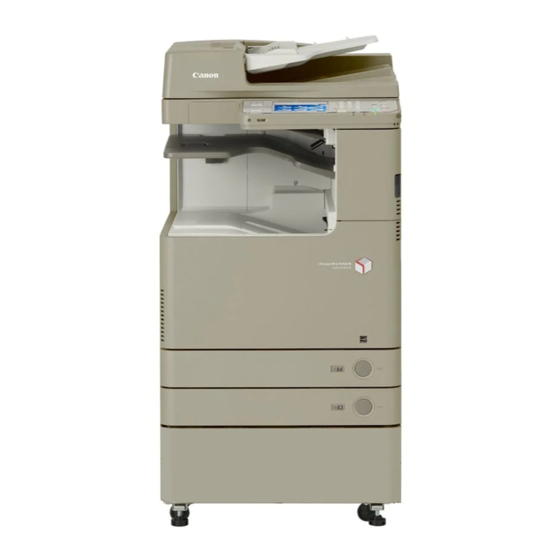
Features/Specifications Features/Specifications > Parts Name > External View 1-11 Parts Name External View [10] [11] [12] F-1-8 DADF Cassette 1 Main Power Switch Front Cover Multi-purpose Tray First Delivery Tray Cassette 4 [10] Control Panel Cassette 3 [11] Rear Upper Cover Cassette 2 [12] Rear Cover 1-11... -
Page 25: Cross Section View
Features/Specifications Features/Specifications > Parts Name > Cross Section View 1-12 Cross Section View Reverse Roller [16] Secondary Transfer Inner [31] Drum Unit (Bk) Roller Duplex/Delivery Unit [17] Secondary Transfer Outer [32] Toner Container (C) Roller Second Delivery Roller [18] Registration Roller [33] Drum Unit (C) Third Delivery Flapper [19] Registration Unit... -
Page 26: Operation
Features/Specifications Features/Specifications > Operation > Power Switch > Points to Note on Turning ON/OFF the Power Switch 1-13 Operation ■ Points to Note on Turning ON/OFF the Power Switch • Be sure to turn OFF the Main Power Switch when turning off the power. Power Switch (There is no need to perform the shutdown sequence which has been performed with the conventional machines.) -
Page 27: Control Panel
Features/Specifications Features/Specifications > Operation > Control Panel > Main Menu 1-14 Control Panel ■ Main Menu iR ADVANCE C2030/2025/2020 series ■ Control Panel iR ADVANCE C2030/2025/2020 series Main Menu Select a function. Show All [15] [14] Scan and Copy Send Fax/I-Fax Secured Tutorial... - Page 28 Features/Specifications Features/Specifications > Operation > Control Panel > Settings/Registration Menu 1-15 ■ Difference of Main Menu ■ Settings/Registration Menu iR ADVANCE iR ADVANCE C2030/2025/2020 series iRC 3380/2880 series C2030/2025/2020 series Copy Copy Select an item to set. Send/Fax Scan and Send/Fax Mail Box Scan and Save Access Stored Files...
-
Page 29: Service Mode
Features/Specifications Features/Specifications > Operation > Service mode > Service Mode Menu 1-16 Service mode Preferences Set Destination Adjustment/Maintenance Management Settings It is possible to see each item of service mode so that those who access to service mode can Function Settings understand how to use them. - Page 30 Features/Specifications Features/Specifications > Operation > Service mode > Enhanced I/O Information 1-17 ■ Description of Service Mode Items ■ Enhanced I/O Information The description of the initial screen, the main items, the intermediate items and the sub items This is the mode to check signal's input/output state of electrical parts (e.g. sensor, motor, can be displayed.
- Page 31 Features/Specifications Features/Specifications > Operation > Service mode > The description of error code/alarm code is displayed 1-18 ■ The description of error code/alarm code is displayed Alarm Code: COPIER > DISPLAY > ALARM-2 Description of each code is available on the error code/alarm code log screen. Error Code: COPIER >...
- Page 32 Features/Specifications Features/Specifications > Operation > Service mode > Security Support 1-19 ■ Classification of COPIER > OPTION > BODY ■ Security Support It has been difficult to find target item because the existing machine has so many items in A password can be specified to prevent an unauthorized access to the service mode. COPIER >...
- Page 33 Features/Specifications Features/Specifications > Operation > Service mode > Specifications of User Messages Related to Consumable Parts 1-20 ■ Switching the Screen Display (Level 1 <->2) ■ Specifications of User Messages Related to Consumable Parts Switching of screens between Level 1 and Level 2 becomes easier. This machine displays life warning messages, which prompt a user to replace consumable By pressing <LEVEL 1>...
- Page 34 Features/Specifications Features/Specifications > Operation > Service mode > Specifications of User Messages Related to Consumable Parts 1-21 Life Parts Method to display the part warning Place of menu on UI Points to note name counter initialization menu message Pickup None Set the service mode Adjustment/ Roller/...
-
Page 35: Process/Operation
Process/Operation ■ Basic Configuration ■ Main Controller ■ Laser Exposure System ■ Image Formation System ■ Fixing System ■ Pickup Feed System ■ External Auxiliary System ■ MEAP ■ Embedded RDS ■ Updater Process/Operation... -
Page 36: Functional Configuration
Process/Operation > Basic Configuration > Functional Configuration Basic Configuration Functional Configuration The machine may broadly be divided into the following functional system blocks; document exposure system block, controller system block, laser exposure system block, image formation system block, fixing system block and pickup/feed system block. Document exposure system Reader relay PCB Exposure lamp... -
Page 37: Basic Sequence
Process/Operation > Basic Configuration > Basic Sequence > A4 single-sided 2 prints full color Basic Sequence ■ A4 single-sided 2 prints full color Start key ON Imaging ready timing Printer unit PSTBY PINTR PRINT LSTR Drum motor (YMC) ITB motor (Bk drum, Developing) Primary charging AC bias (Y) Neutralizes electric charge on the Drum... - Page 38 Process/Operation > Basic Configuration > Basic Sequence > A4 single-sided 2 prints full color Start key ON Imaging ready timing Printer unit PSTBY PINTR PRINT LSTR Developing motor(YMC) Primary transfer bias(Y) Drum cleaning Primary transfer bias(M) Drum cleaning Primary transfer bias(C) Drum cleaning Primary transfer bias(Bk) Drum cleaning...
- Page 39 Process/Operation > Basic Configuration > Basic Sequence > A4 single-sided 2 prints Bk color ■ A4 single-sided 2 prints Bk color Start key ON Imaging ready timing Printer unit PSTBY PINTR PRINT LSTR Drum motor (YMC) ITB motor (Bk drum, Developing) Primary charging AC bias (Bk) Neutralizes electric charge on the Drum Primary charging DC bias (Bk)
-
Page 40: Main Controller
Process/Operation > Main Controller > Overview > Specifications/ Configuration Main Controller ■ Specifications/ Configuration ● PCBs Overview ■ Features Introduction of the new controller enables high speed PDL processing, high image quality and high functionality. TPM PCB Flash PCB F-2-6 Main controller PCB 1 Main controller PCB 2 F-2-5... - Page 41 Process/Operation > Main Controller > Overview > Specifications/ Configuration ● Memory Devices Parts name Functions, specifications and features Main Controller PCB 1 CPU: 1.2 GHz, Controls the entire system. Main Controller PCB 1 Various controls (memory, Control Panel, electric power, voice), I/F DDR2-SDRAM 512MB Backup Battery Boards (PCI, USB (host)), RTC...
- Page 42 Process/Operation > Main Controller > Overview > Specifications/ Configuration Main Controller PCB 2 ● I/F, Connector Main Controller PCB 1 SRAM Backup Battery External I/F Voice guide Internal I/F J1002 DDR2-SDRAM 1GB SRAM J1003 Control Panel J1007 Mini-USB J1015 J1017 J1019 J1018 Main controller PCB 2...
- Page 43 Process/Operation > Main Controller > Overview > Specifications/ Configuration Main Controller PCB 2 Functions and specifications DC Controller PCB Power supply control / Main Controller PCB 1 I/F Power Supply Fan I/F External I/F Reader Reader Internal I/F HDD signal J8113 J8141 Memory PCB...
- Page 44 Process/Operation > Main Controller > Overview > Specifications/ Configuration 2-10 ● Function Expansion Options Main Controller PCB 2 Main Controller PCB 1 Voice Guidance PCB Image Data Analyzer PCB F-2-12 Name Functions, specifications and features Image Data Analyzer Product name: Image Data Analyzer PCB-A1 PCI Expansion PCB IPSec PCB Wireless LAN PCB...
- Page 45 Process/Operation > Main Controller > Overview > Flash model and HDD model 2-11 ■ Flash model and HDD model HDD model The 80GB HDD is used together with the 4GB flash memory. The system data is stored in the The partition and usage pattern differ between the flash memory model and the HDD model. flash memory while the image/other data is stored in the HDD.
- Page 46 Process/Operation > Main Controller > Overview > Flash model and HDD model 2-12 Difference in specifications of respective applications when installing the HDD option The following table shows the applications to which the specification is changed when installing the HDD option. Those without change of specifications are indicated with “-“while those with change of specifications are indicated with the “description of changed specifications”.
- Page 47 Process/Operation > Main Controller > Overview > Shutdown Sequence 2-13 ■ Boot Sequence Related error codes (major error codes): Error codes Error description E602 HDD error Power Supply Switch ON 0001 HDD detection error Unable to find the startup partition (BOOTDEV) at startup. [ ] : Program storage location 0002 File system error on the HDD...
-
Page 48: Controls
Process/Operation > Main Controller > Controls > Flow of Image Data 2-14 Controls ● SEND ■ Flow of Image Data Network Reader Red line..If there is HDD, the data goes in HDD. If there is not HDD, the data goes in Flash memory. - Page 49 Process/Operation > Main Controller > Controls > Flow of Image Data 2-15 ● Fax SEND Reader Image Processing Flash Resolution Conversion JBIG・MMR/MH Image rotation Conversion Image Level Cell HDD Writing/ Reading Image Data Buffer (Memory) Main Controller Main Controller PCB1 PCB2 F-2-19 ●...
-
Page 50: Security
Process/Operation > Main Controller > Security > Setting the Management on the Hard Disk 2-16 Security ● Initializing All Data/Settings ■ Setting the Management on the Hard Disk Initializing the saved file and the registration information This function enables to delete (initialize) the data such as the file saved in the host machine, In addition to the document data to be accumulated by FAX function, the registration the registration information of the Address Book and the job log information* information of the Address Book and the password information of the System Box and the... - Page 51 Process/Operation > Main Controller > Security > The procedure to disable the HDD license transfer 2-17 ■ Installation procedure of the HDD ■ The procedure to disable the HDD license transfer The iR-ADV C2020 series has the flash memory model and the HDD model respectively. For transferring the HDD license in the case of replacing a device, this function is used to To upgrade a flash memory model to a HDD model, the license registration is required in disable the license and move the HDD option to the other device.
- Page 52 Process/Operation > Main Controller > Security > Delete Old Data 2-18 • Before disabling the HDD license transfer, the license depending on HDD such as Secure • Program and library at the time of factory shipment print or PS must be disabled. •...
- Page 53 Process/Operation > Main Controller > Security > Delete Old Data 2-19 Basic concept for “Delete Old Data” 4.Using the HDD 1.Using the flash memory F-2-29 F-2-26 2.At the time of increasing a HDD or license registration F-2-27 3.”Delete Old Data” in user mode F-2-28 2-19 Process/Operation >...
- Page 54 Process/Operation > Main Controller > Security > Security features(encryption key and certificate, password protection) 2-20 ■ Security features(encryption key and certificate, password protection) On the Main Controller PCB 1 of the main body, “TPM PCB” is equipped. TPM stands for Trusted Plattform Module, and is the chip name which generates and stores the encryption key and has the encryption calculation function for the public key.
- Page 55 Process/Operation > Main Controller > Security > Security features(encryption key and certificate, password protection) 2-21 ● Configuration of Security Information information in the SRAM even after the password information is initialized. The security functionality behaves differently depending on the TPM setting on the UI.This machine provides the two types of TPM settings.
- Page 56 Process/Operation > Main Controller > Security > Security features(encryption key and certificate, password protection) 2-22 ● Preparation before Installing TPM ● Before / after introduction Before installing TPM, ask the user to back up data.Follow the steps below to back up data. The setting neeeds to be specified in Settings / Registration mode (“TPM setting”...
- Page 57 Process/Operation > Main Controller > Security > Security features(encryption key and certificate, password protection) 2-23 1. Enable the feature 2) Click “Yes”, and then reboot this machine. Setting of “system management encryption number” Recommend the user (administrator) to set up the system management encryption number in advance.
- Page 58 Process/Operation > Main Controller > Security > Security features(encryption key and certificate, password protection) 2-24 2. Backup of TPM key 3) Click [Password] to enter the password (4 to 12-digit), and then enter the password to Only the USB memory (supported system file: FAT32) can be used as the device for saving confirm the entry.
- Page 59 Process/Operation > Main Controller > Security > Security features(encryption key and certificate, password protection) 2-25 3. Restore of TPM Key Caution: Procedure is about the same as the backup work. Cause of backup failure Difference between restore work and backup work: In the case of the following, a message is shown indicating backup failure and its cause.
- Page 60 Process/Operation > Main Controller > Security > Security features(encryption key and certificate, password protection) 2-26 Caution: Caution: Points to note when disabling functionality Cause of restore failure To disable the use of TPM, all data and settings should be initialized. If this is executed, user information saved in the HDD/ SRAM is totally cleared.
- Page 61 Process/Operation > Main Controller > Security > Security features(encryption key and certificate, password protection) 2-27 ● Related Error Code ● Data to be encrypted / decoded(reference) Error Code Error title, description, remedy Flash model E746 Error in encryption 0031 Engine ID error Type Application/feature Security information...
- Page 62 Process/Operation > Main Controller > Security > Security features(encryption key and certificate, password protection) 2-28 HDD model Type Application/feature Security information Saving destination Password/encryption FAX Box Password for FAX Box number Send Password for File destination in Address Book Password of LDAP server SRAM Password of POP3 server SRAM...
- Page 63 Mirroring function is built in the HDD Encryption Kit - C3, however, the HDD for mirroring than E602-2000 error) cannot be installed with the imageRUNNER ADVANCE C2030/C2025/C2020 series. Since Case 3: E602-2000 is triggered by failure in mutual authentication mirroring is not available, the following explains the encryption function of the HDD.
- Page 64 Process/Operation > Main Controller > Security > HDD Encryption Kit (Optional) 2-30 Servicing User data Recovery Action Main controller clear Information After MN-CON clear MN-CON clear does not clear held in SRAM process is done authentication information; no work cleared is required specifically for HDD encryption kit T-2-13...
-
Page 65: Service Tasks
Process/Operation > Main Controller > Service Tasks > Service Notes 2-31 Service Tasks ■ Actions at Parts Replacement Reference to the section 5. ■ Periodically Replaced Parts None. ■ Consumable Parts None. ■ Service Notes None. 2-31 Process/Operation > Main Controller > Service Tasks > Service Notes... -
Page 66: Laser Exposure System
Process/Operation > Laser Exposure System > Overview > Overview 2-32 Laser Exposure System Main Controller Overview ■ Overview DC Controller Laser exposure system forms the electrostatic latent image on the photosensitive drum by the laser exposure. [ 8] [ 9] This system is composed of the laser assembly and the scanner motor assembly that are unified as the laser scanner unit. - Page 67 Process/Operation > Laser Exposure System > Overview > 1-Polygon 4-Laser Method 2-33 ■ 1-Polygon 4-Laser Method drum drum drum drum This method uses 1 scanner motor (polygon motor) and 4 laser diodes to execute laser scanning. This method allows to emit the 4 lasers on the multi-facet mirror on one scanner motor contributing to space-saving.
- Page 68 780 to 800nm Laser type Red color laser (non-visible light) Laser output Number of laser scanner unit 1 Number of laser light imageRUNNER ADVANCE C2030/C2025/C2020 : 1 beam for each color Resolution 600dpi/1200dpi Motor type Brushless motor Number of motor rotation imageRUNNER ADVANCE C2030/C2025/C2020 Approx.38268rpm(1/1-speed,1/2-speed)
-
Page 69: Various Controls
Process/Operation > Laser Exposure System > Various Controls > Laser ON/OFF control 2-35 ■ Laser ON/OFF control Various Controls ● Purpose ■ Overview Laser light is turned ON / OFF according to the combination of laser control signal. Item Operation description Laser ON / OFF control Laser light is turned ON / OFF according to the combination of laser ●... - Page 70 Process/Operation > Laser Exposure System > Various Controls > Horizontal scanning synchronous control 2-36 ■ Horizontal scanning synchronous control Main Controller ● Purpose To align the writing start position in horizontal scanning direction. ● Execution timing DC Controller Per 1 line ●...
- Page 71 Process/Operation > Laser Exposure System > Various Controls > Vertical Scanning Synchronous Control 2-37 ■ Vertical Scanning Synchronous Control Main Controller ● Purpose This is to align the writing start position in vertical scanning direction. ● Execution timing DC Controller Per color, Per printing ●...
- Page 72 Process/Operation > Laser Exposure System > Various Controls > Laser scanner motor control 2-38 ■ Image Mask Control ■ Laser scanner motor control ● Purpose ● Purpose This control prevents the laser beam from being emitted in non-image area to avoid the This is to rotate the scanner mirror by the specified speed.
- Page 73 Process/Operation > Laser Exposure System > Various Controls > Dustproof shutter control 2-39 ■ APC(Auto Power Control) Control ■ Dustproof shutter control ● Purpose ● Purpose This is to make the laser light for 1 line consistent amount. This is to prevent the residue toner from sticking to the dust-prevention glass. Or to prevent the laser light from emitting to the machine inside when the front cover / right cover is opened.
- Page 74 Process/Operation > Laser Exposure System > Various Controls > Dustproof shutter control 2-40 <Shutter: close> <Shutter: open> Shutter Lever Shutter Cam Dustproof Shutter Shutter Cam Drive Shaft Shutter Motor (M5) Dustproof Shutter Sensor (PS5) Front Cover Sensor (PS34) Controller(UN9) Right Cover Sensor (PS35) F-2-55 2-40...
-
Page 75: Servicing
Process/Operation > Laser Exposure System > Servicing > Actions at Parts Replacement 2-41 Servicing ■ Periodically Replaced Parts There is no part that required periodical replacement. ■ Consumable Parts There is no consumable part. ■ List of Periodical Service Works Part name: Dustproof Glass Estimated life: every 50000 sheets Actions:... -
Page 76: Overview
30mm dia. Cleaning Cleaner-less method ■ Overview Process speed imageRUNNER ADVANCE C2030 = 135mm/s imageRUNNER ADVANCE C2020 = 135mm/s Image formation system of this machine uses the non-magnetic 2-component AC developing Drum Heater None method for developing and the intermediate transfer method for transferring to form toner... - Page 77 Process/Operation > Image Formation System > Overview > Print Process 2-43 ■ Parts Configuration ■ Print Process ● Major Parts ● Overview Drum Unit ITB cleaning block Delivery 8.ITB cleaning Transfer Fixing block Unit 7.Fixing 4.Primary transfer 3.Development 4.Primary transfer Transfer block Developing Photosensitive...
- Page 78 Process/Operation > Image Formation System > Overview > Print Process 2-44 ● Bias Types Static latent image 1 Primary The surface of the Photosensitive Drum is charged to make a formation block charging uniform negative potential. The following 9 types of bias are used with this machine. 2 Laser Emission of the laser light forms a static latent image on the Bias value...
-
Page 79: Controls
Process/Operation > Image Formation System > Controls > Primary Charging 2-45 Controls ■ Primary Charging ■ Overview ● Overview This machine uses the roller charging method for primary charging. Primary charging Image stabilization control Primary charging bias control D-max control Discharge current control PASCAL control Photosensitive Drum... - Page 80 Process/Operation > Image Formation System > Controls > Primary Charging 2-46 ● Primary Charging Bias Control ● Discharge Current Control/Simple Discharge Current Control The surface of the Photosensitive Drum is charged to make a uniform negative potential. Optimal primary charging bias is applied according to the environment change or use of the The primary charging bias (AC + DC negative), which has been generated by the Primary Photosensitive Drum.
- Page 81 Process/Operation > Image Formation System > Controls > Drum Unit (Developing/Drum) 2-47 ■ Drum Unit (Developing/Drum) ● Developing Overview/ Drive Configuration ● Drum Unit Overview Developing Cylinder Toner Feed Screw B The Drum Unit consists of the Developing Assembly and the Drum Assembly. Drum Assembly Developing Assembly ATR Sensor...
- Page 82 Process/Operation > Image Formation System > Controls > Drum Unit (Developing/Drum) 2-48 ● Developing bias control ● Drum Overview A toner image is formed on the Photosensitive Drum by attaching toner to the Developing Photosensitive Drum Upstream Brush Cylinder. Control description The developing bias (AC, DC negative), which has been generated on the Develop High Voltage PCB (UN9), is applied to the Developing Cylinder.
- Page 83 Process/Operation > Image Formation System > Controls > Drum Unit (Developing/Drum) 2-49 ● Drive Configuration ● Drum Unit Detection Whether the Drum Unit is installed or not is detected. Drum Motor(M4) Photosensitive ITB Motor(M2) Drum Detection timing 1) At power-on, at recovery from sleep mode, when the Front Door is opened/closed. Upstream Brush Detection description 1) The memory tag of the Drum Unit is detected.
- Page 84 Process/Operation > Image Formation System > Controls > Drum Unit (Developing/Drum) 2-50 ● Drum Unit Life Detection ● Drum Phase Control Life of the Drum Unit (Photosensitive Drum) is detected. Overview There can be uneven rotation speed of the Drum because the shapes of the Drive Gears Detection timing (that rotate the Drum) slightly differ with each other.
- Page 85 Process/Operation > Image Formation System > Controls > Transfer/Separation 2-51 ■ Transfer/Separation ● Drive Configuration ● Overview Drum Motor Fixing Motor Primary Transfer The ITB Unit transfers a toner image on the Photosensitive Drum onto the ITB. Then, the Disengagement Solenoid toner image is transferred on the paper.
- Page 86 Process/Operation > Image Formation System > Controls > Transfer/Separation 2-52 ● Primary Transfer Roller Disengagement Control ● Primary Transfer Bias Control The Primary Transfer Roller is usually engaged. The Primary Transfer Roller needs to be The primary transfer bias is divided into each color (Y, M, C, Bk) to be generated on the disengaged when a part is replaced;...
- Page 87 Process/Operation > Image Formation System > Controls > Transfer/Separation 2-53 ● Secondary Transfer Bias Control ● ITB Displacement Correction Control Toner on the ITB is transferred to a paper. The ITB displacement correction control corrects displacement of the ITB to prevent tear of The secondary transfer bias (TR2), which has been generated on the secondary transfer bias the ITB (caused by displacement of the ITB).
- Page 88 Process/Operation > Image Formation System > Controls > Transfer/Separation 2-54 ● ITB Cleaning Control ● Secondary Transfer Outer Roller Cleaning Control Residual toner on the ITB is removed. Soiling at the back of the sheet caused by soiling of the Secondary Transfer Outer Roller can be prevented.
- Page 89 Process/Operation > Image Formation System > Controls > Drum Cleaning 2-55 ● Separation ■ Drum Cleaning This control separates paper from the ITB by elastic force of the paper (curvature separation ● Overview method). There is no Drum Cleaner with this machine. In the case of thin paper which has low elastic force, the Static Eliminator removes positive This machine uses the 2 Auxiliary Brushes to control polar character of residual toner and the potential at the back of the paper.
- Page 90 Process/Operation > Image Formation System > Controls > Drum Cleaning 2-56 ● Auxiliary Brush Control ● Brush Discharge Control By controlling the polar character of the transfer-residual toner on the surface of the Toner accumulated with the Auxiliary Brush is discharged to maintain performance of the Photosensitive Drum, attachment of the toner to the Primary Charging Roller is prevented Auxiliary Brush.
- Page 91 Process/Operation > Image Formation System > Controls > Image Stabilization Control 2-57 ■ Image Stabilization Control ● Control timing Execution items for image stabilization control differ according to the environment and ● Overview condition of image formation parts. Image failure due to change of the environment or deterioration of the Photosensitive Drum is Following shows the control items at each sequence and estimated downtime.
- Page 92 Process/Operation > Image Formation System > Controls > Image Stabilization Control 2-58 ● D-max Control Control type The optimal developing DC bias, primary charging bias and laser output are determined Control timing 1) When replacing the Drum Unit 2) At last rotation on a specified print basis Conditions for execution 3) At power-on in H/H environment 4) At recovery from sleep mode...
- Page 93 Process/Operation > Image Formation System > Controls > Image Stabilization Control 2-59 ● PASCAL control Gradation density characteristics on the image are stabilized. Start This control is executed when the following is selected in user mode: Auto Adjust Gradation > Full Adjust.
- Page 94 Process/Operation > Image Formation System > Controls > Image Stabilization Control 2-60 NOTE: Start The following 3 types of patch patterns are formed with this control: • A pattern for copy (64 patches for each color) Main controller 2 • A pattern for text (64 patches for each color) •...
- Page 95 Process/Operation > Image Formation System > Controls > Image Stabilization Control 2-61 ● D-half Control Optimal image gradation is determined. Control timing 1) When replacing the Drum Unit 2) At last rotation on a specified print basis 3) When executing PASCAL control 4) At recovery from sleep mode Control description 1) Main Controller PCB 2 outputs patch data in each color (Y, M, C, and Bk) to the DC...
- Page 96 Process/Operation > Image Formation System > Controls > Image Stabilization Control 2-62 The flow to calculate correction value for ARCDAT control Start Start Main controller 2 Main controller 2 (UN12) Output of patch pattern data Patch pattern is created DC controller (UN9) DC controller (UN9) Patch pattern is created Reference data for...
- Page 97 Process/Operation > Image Formation System > Controls > Image Stabilization Control 2-63 ● ARCDAT Control (Automatic and Reciprocal Color Density Adjustment Technology) While reducing downtime, the ideal gradation characteristics are realized. Control timing 1) When replacing the Drum Unit 2) At power-on 3) At paper interval on a specified print basis or at last rotation 4) At recovery from sleep mode Control description...
- Page 98 Process/Operation > Image Formation System > Controls > Image Stabilization Control 2-64 ● Color Displacement Correction Control Start Uneven exposure of the Laser Scanner Unit and color displacement caused by uneven rotation of the drum or the ITB is corrected. Main Controller 2 (UN12) Output of patch pattern data ITB Unit...
- Page 99 Process/Operation > Image Formation System > Controls > Image Stabilization Control 2-65 temperature). Drum Unit Toner Feed Screw C 2) Exposure timing for YMC is adjusted with reference to Bk. 3) When the log for color displacement becomes large, the color displacement correction is performed with the patch pattern above.
- Page 100 Process/Operation > Image Formation System > Controls > Image Stabilization Control 2-66 ● ATVC Control Related error codes Transfer failure due to environmental change or deterioration of the Primary Transfer Roller or X indicates the target color (1=Y, 2=M, 3=C, 4=Bk) E020-0XB0: The TD ration detected by ATR Sensor is higher than the specified value the Secondary Transfer Roller can be prevented.
- Page 101 Process/Operation > Image Formation System > Controls > Toner Supply Assembly 2-67 ■ Toner Supply Assembly ● Toner Cap Opening A cap of the Toner Container is opened/closed in conjunction with opening and closing the ● Overview Toner Container Cover. Toner is supplied from the Toner Container to the Developing Assembly.
- Page 102 Process/Operation > Image Formation System > Controls > Toner Supply Assembly 2-68 ● Toner Supply Control/Toner Level Detection Toner Level Detection Toner is supplied from the Toner Container to the Developing Assembly. At the same time, Detection Detection timing Detecting to Message toner level in the Hopper Unit is detected.
- Page 103 Process/Operation > Image Formation System > Controls > Waste Toner Feeding Area 2-69 ■ Waste Toner Feeding Area ● Waste Toner Container Full Level Detection Toner level accumulated in the Waste Toner Container is detected. ● Overview This machine uses a weight-based detection mechanism. When waste toner is accumulated, Waste toner in the ITB Cleaning Unit is fed to the Waste Toner Container.
- Page 104 Process/Operation > Image Formation System > Controls > Waste Toner Feeding Area 2-70 Before Cont v35.02, Dcon v62.02 ● Adjustment mode of Waste Toner Container preparation warning timing (Setting of service mode > COPIER > OPTION > CUSTOM > Detection Warning for full level of waste toner Full level of waste toner (approx.
- Page 105 Process/Operation > Image Formation System > Controls > Waste Toner Feeding Area 2-71 B: Varies according to the EXT-TBOX value Service mode Display timing of Waste Toner Container preparation warning Embossed line setting value "0" (Default When Waste Toner Full Sensor is turned ON setting) Line above label "1"...
- Page 106 Process/Operation > Image Formation System > Controls > Waste Toner Feeding Area 2-72 ● Adjustment mode of Waste Toner Container preparation warning C: Varies according to the EXT-TBOX value timing (Setting of service mode > COPIER > OPTION > CUSTOM > Service mode Display timing of Waste Toner Container preparation warning setting value...
- Page 107 Process/Operation > Image Formation System > Controls > Other Controls 2-73 ● Waste Toner Container Detection ■ Other Controls Presence/absence of the Waste Toner Container is detected. ● Special Controls This machine has the following sequences as the special sequence. Detection timing Image Smear Prevention Developing Discharge...
-
Page 108: Service Tasks
Process/Operation > Image Formation System > Service Tasks > List of Periodical Service Works 2-74 Service Tasks ■ Periodically Replaced Parts None ■ Consumable Parts Parts name Parts Quantity Estimated life Remarks number ITB Unit FM3-8240 150,000 images Old Type : FM3-8240 FM1-F555 New Type : FM1-F555 Secondary Transfer... -
Page 109: Fixing System
Process/Operation > Fixing System > Overview > Features 2-75 Fixing System 1. Applying a "service-less" Fixing Assembly To replace the Fixing Assembly, a simple replacement procedure in which fixing screws do Overview not have to be removed is realized for improving the serviceability. ■... - Page 110 Process/Operation > Fixing System > Overview > Major Components 2-76 ■ Specifications ■ Major Components Item Function/method Fixing method On-demand fixing Fixing Film Fixing speed 135 mm/s (1/1 speed, plain paper) 67.5 mm/s (1/2 speed, heavy paper, long length heavy paper: SRA3, 12"×18") Heater Aluminum Heater...
-
Page 111: Controls
Process/Operation > Fixing System > Controls > Standby Temperature Control 2-77 Controls ■ Standby Temperature Control ■ Overview of Fixing Temperature Control Fixing temperature STBY INTR PRNT Fixing temperature STBY INTR PRNT Flaying start control Flying start Startup During-print Sheet-t temperature control (warm-up... - Page 112 Process/Operation > Fixing System > Controls > Print Temperature Control 2-78 ■ Print Temperature Control ● Print temperature control An appropriate target temperature is set according to the number of sheets, paper type, and Fixing environment at continuous printing. temperature A temperature of the Fixing Heater is controlled according to the result of detection by the STBY INTR...
- Page 113 Process/Operation > Fixing System > Controls > Down Sequence Control 2-79 ● Paper interval temperature control ■ Down Sequence Control A paper interval temperature is decreased to prevent temperature increase when the paper ● Down sequence when small-size paper is fed interval became wider than a normal condition Heater drive signal (FSRD1, 2) Paper Interval Temperature = Target temperature during printing - (15 to 30 deg C)
- Page 114 Process/Operation > Fixing System > Controls > Down Sequence Control 2-80 Operation: ● Down sequence when the paper size is switched A temperature is decreased by increasing a paper interval, and the temperature is Purpose: controlled at a slightly lower level than the target temperature at normal printing During continuous printing, when a succeeding sheet with a wider width than a preceding Target Print...
- Page 115 Process/Operation > Fixing System > Controls > Film Unit Engagement/Disengagement Control 2-81 ■ Film Unit Engagement/Disengagement Control Execution condition/timing of engagement Execution condition/timing of disengagement operation: operation: The Fixing Film Unit is disengaged from the Pressure Roller under a specific condition •...
- Page 116 Process/Operation > Fixing System > Controls > Fixing Arch Control 2-82 ■ Fixing Arch Control DC Controller This machine executes fixing loop control to prevent image and feeding failures. Loop Sensor 2 Flag Fixing loop control is executed to prevent image and feeding failures by keeping the slack of for papers other than paper between the Secondary Transfer Outer Roller and Pressure Roller to a specified level.
- Page 117 Process/Operation > Fixing System > Controls > Fixing Assembly Detection 2-83 <A> <B> <C> ■ Fixing Assembly Detection Slack of paper is small. Slack of paper is large. Slack of paper is large. (Heavy paper) (Other than heavy paper) Presence of the Fixing Assembly is judged by a Fixing Assembly detection signal (/FSR_ OPEN), which is input to the DC Controller at warm-up rotation (power-on, opening the PS22 cover).
- Page 118 Process/Operation > Fixing System > Controls > Protection function 2-84 ■ Protection function Clearing Code Description of error Clearing Code Description E004 Detection of a failure in fixing heater drive circuit of error 0001 Fixing Relay welding detection error E001 Detection of abnormal high temperature needed.
-
Page 119: Service Tasks
Process/Operation > Fixing System > Service Tasks > Actions at Parts Replacement 2-85 Service Tasks ■ Periodically Replaced Parts None. ■ Consumable Parts Estimated Parts Counter Parts name Quantity life Adjustment Remarks number (DRBL-1) (sheets) 1 Fixing Assembly FM1-B289 150000 FX-UNIT None 100V... -
Page 120: Pickup Feed System
Process/Operation > Pickup Feed System > Overview > Specification 2-86 Pickup Feed System ■ Specification Item Description Paper storage method Front loading method Overview Pickup Cassette 1 Simple Separation Roller method (Pickup Roller + Separation Roller) method Cassette 2 Separation Roller method (Pickup Roller + Delivery Roller + Separation ■... - Page 121 Process/Operation > Pickup Feed System > Overview > Parts Configuration 2-87 ■ Parts Configuration Reverse Roller [11] Merging Roller Second Delivery Roller [12] Cassette 1 Vertical Path Roller ● Roller Layout Drowing Third Delivery Roller [13] Cassette 1 Pickup Roller Second / Third Delivery Inlet Roller [14] Cassette 1 Separation Roller...
- Page 122 Process/Operation > Pickup Feed System > Overview > Parts Configuration 2-88 ● Sensor/Switch Layout Drawing PS10 Multi-purpose Tray Paper Sensor PS25 First Delivery Tray Paper Full Sensor PS11 Multi-purpose Tray Last Paper Sensor PS27 Second Delivery Sensor PS12 Cassette Lifter Sensor PS28 Second Delivery Tray Full Sensor PS13...
- Page 123 Process/Operation > Pickup Feed System > Overview > Parts Configuration 2-89 ● Load Driving Drawing Cassette 1 Pickup Motor Multi-purpose Tray Pickup Solenoid Cassette 2 Pickup Motor Cassette 1 Pickup Solenoid Fixing Motor Cassette 2 Pickup Solenoid Fixing Outlet Motor First Delivery Flapper Solenoid Duplex Feed Motor Second Delivery Flapper Solenoid...
- Page 124 Process/Operation > Pickup Feed System > Overview > Paper path 2-90 ■ Paper path Reverse Mouth Third Delivery Second Delivery First Delivery Multi-purpose Tray Pickup Cassette 1 Pickup Cassette 2 Pickup F-2-120 To feed heavy paper, the feed path in the Duplex Feed Assembly is made gently curved to minimize damage to the paper.
-
Page 125: Various Controls
Process/Operation > Pickup Feed System > Various Controls > Cassette Pickup Assembly 2-91 Various Controls Area Detection,Control JAM Detection JAM Detection ■ Overview T-2-52 ■ Cassette Pickup Assembly ● Parts Configuration Duplex/Delivery Cassette 1 Pickup Motor (M15) Cassette 1 Cassette 1 Pickup Solenoid Vertical path Roller (SL4) - Page 126 Process/Operation > Pickup Feed System > Various Controls > Paper Size Detection / Cassette Presence Detection 2-92 ■ Paper Size Detection / Cassette Presence Detection Cassette 1 Size Switch A Cassette 1 Size Switch B ● Cassette 1 The Cassette 1 Size Switch A/B detects the size of the paper set in the cassette. Length and width are detected according to the ON / OFF combination of switches.
- Page 127 Process/Operation > Pickup Feed System > Various Controls > Paper Size Detection / Cassette Presence Detection 2-93 Cassette Size Switch B Size switch A Trailing Edge Guide Plate A-① Size switch B A-② A-③ B-① B-② Detection Dial Trailing Edge Guide Plate B-③...
- Page 128 Process/Operation > Pickup Feed System > Various Controls > Paper Size Detection / Cassette Presence Detection 2-94 ● Cassette 2 NOTE: Paper size of the cassette can be automatically detected by adjusting the position of the • A5R/STMTR Original Selection guide plate.
- Page 129 Process/Operation > Pickup Feed System > Various Controls > Paper Size Detection / Cassette Presence Detection 2-95 Cassette size Size switch B switch A B-① Rear detection B-② rink B-③ B-④ Rear guide plate Size switch A A-① A-② A-③ A-④...
- Page 130 Process/Operation > Pickup Feed System > Various Controls > Paper Level /Presence Detection 2-96 ● Method of Setting Special Paper ■ Paper Level /Presence Detection • Service mode ● Cassette 1 COPIER > OPTION > CST > CSTX-UY > Setting number There are 2 sensors to detect the paper level and paper presence in the cassette.
- Page 131 Overall Cassette paper level sensor B Labels Overall Tub paper Overall Pre-punched paper Overall Canon Europe Canon Recycled 80 Overall (Vision Classic White) Canon Europe Canon High Grade Especially heavy paper 220/250 OFFON (Mondi Business Papar) gsm etc. Canon Digital Office Colour...
- Page 132 Process/Operation > Pickup Feed System > Various Controls > Multi-Purpose Tray Pickup Assembly 2-98 ■ Multi-Purpose Tray Pickup Assembly ● Drive Configuration ● Parts Configuration Multi-purpose Tray Multi-purpose Tray Paper sensor (PS10) Cassette 1 Cassette 1 Pickup Motor Pickup Solenoid Manual feed (SL4) Pickup Solenoid...
- Page 133 Process/Operation > Pickup Feed System > Various Controls > Fixing/Registration Assembly 2-99 ● Multi-Porpose Tray Last Paper Detection ■ Fixing/Registration Assembly This Host Machine detects whether the paper picked up from the Multi-purpose Tray is the ● Parts/Drive Configuration last paper. When pickup is performed from the Multi-purpose Tray, the feed distance from the Multi- purpose Tray Paper Presence Sensor to the Registration Roller is short, hence before the no-paper in the Multi-purpose Tray is detected, the next image is started to be formed.
- Page 134 Process/Operation > Pickup Feed System > Various Controls > Duplex / Delivery Assembly 2-100 ● Skew Correction Mechanism ■ Duplex / Delivery Assembly This Host Machine can correct the skew of the paper without dropping the throughput. ● Parts / Drive Configuration The following figure shows the skew correction mechanism.
- Page 135 Process/Operation > Pickup Feed System > Various Controls > Duplex / Delivery Assembly 2-101 ● Duplex Wait Control Larger than LTR To realize 5-sheet circulation, there are 2 duplex wait positions. Following is the duplex wait position for small paper. LTR or smaller Duplex standby position 73.4mm...
- Page 136 Process/Operation > Pickup Feed System > Various Controls > JAM Detection 2-102 ■ JAM Detection Sensor Name Code 01:Delay 02:Stationary 07:Wrap 0A:Power ON Code Cassette 2 Vertical Path xx02 PS17 ○ × × ○ Sensor xx05 Registration Sensor PS20 ○ ○...
-
Page 137: Service Tasks
Process/Operation > Pickup Feed System > Service Tasks > Periodically Service 2-103 Service Tasks ■ Periodically replacement parts ■ Consumables Number of Replacement Parts Name Parts Number Remarks used part timing Multi-purpose Tray Pickup Roller RM1-6177 150k Multi-purpose Tray Separation Pad RM1-6178 150k Cassette 1 Pickup Roller... -
Page 138: External Auxiliary System
Process/Operation > External Auxiliary System > Controls > Fan 2-104 External Auxiliary System ■ Fan ● Location of Fans Controls Controller Fan(FM3) ■ Software counter Count-up timing differs depending on the following conditions: • Print mode (1-sided/ 2nd side of 2-sided/ 1st side of 2-sided) •... - Page 139 Process/Operation > External Auxiliary System > Controls > Fan 2-105 ● Airflow ● Speed Control Controller Fan(FM3) Among the fans installed with this equipment, the Power Supply Cooling Fan (FM1), the Controller Fan (FM3) and the Delivery Cooling Fan (FM4) execute speed control. Rotation speed is switched by the Power Voltage Switch Circuit of the Controller Fan to switch voltage.
- Page 140 Process/Operation > External Auxiliary System > Controls > Fan 2-106 ● Operation Sequence At printing Sleep Others 3 Way 1-sided 2-sided Reader Fan type Standby Unit-C1 2nd/3rd delivery, 2nd/3rd delivery, Sleep1 Deep Sleep ERR / JAM 1st delivery 1st delivery operation Finisher Finisher...
-
Page 141: Power Supply Control
Process/Operation > External Auxiliary System > Power Supply Control > Power supply connection with the options 2-107 Power Supply Control ■ Power supply connection with the options ■ Power supply distribution inside the printer Reader / ADF Unit Power Supply Switch AC Driver PCB 3.3V FU101... - Page 142 Process/Operation > External Auxiliary System > Power Supply Control > Energy Saving Function 2-108 ■ Energy Saving Function Sleep 1 In the case of the following: The power supply mode of this equipment is divided into the “Standby” mode and the “Sleep” User Mode >...
- Page 143 Process/Operation > External Auxiliary System > Power Supply Control > Energy Saving Function 2-109 The following descriptions are conditions for not entering DEEP SLEEP. Hardware status • The Serial Coin Vendor is connected. • The EFI (Video Option Board) is installed. Software status •...
- Page 144 Process/Operation > External Auxiliary System > Power Supply Control > Energy Saving Function 2-110 The Alarm Service is set to within 12 minutes. • * When one of the following is being executed, the Alarm Service (Time) is set. • - Time setting for ON/OFF of the Memory Lock •...
-
Page 145: Service Tasks
Process/Operation > External Auxiliary System > Service Tasks > Service Notes 2-111 Service Tasks ■ Actions at Parts Replacement None. ■ Periodically Replaced Parts None. ■ Consumable Parts None. ■ Service Notes None. 2-111 Process/Operation > External Auxiliary System > Service Tasks > Service Notes... -
Page 146: Meap
Process/Operation > MEAP > Checking the Operating Environment > SMS 2-112 MEAP Checking the Operating Environment ■ Outline Changes This section lists the requirements on the operating environment for the maintenance. ■ Control Panel Display Specifications Note: • The control panel display specifications were changed in iR-ADV C2030/C2025/C2020 •... - Page 147 Process/Operation > MEAP > Checking the Operating Environment > SSO-H Management 2-113 ■ SSO-H Management System environments for administrator and ordinary user Java Runtime When using SSO-H for the login service, required system environments are different in Operating System Supported browser Environment domain authentication or local device authentication.
- Page 148 Windows Server 2003 R2 SP2 Windows Internet Explorer 7 • The user who belongs to the group named "Canon Peripheral Admins" on Active Directory is authenticated as a manager by the domain authentication. Create the group named Windows Server 2008 SP2 Windows Internet Explorer 8 "Canon Peripheral Admins"...
-
Page 149: Setting Up The Network
Process/Operation > MEAP > Setting Up the Network > Network configuration process 2-115 Setting Up the Network Note: When using SSL, press [Settings/ Registration] button, select [Management ■ Network configuration process Settings]>[License / Other] > [MEAP Settings] > [SSL Settings] and press [On] button. (This setting is applied to SSL setting on RUI. -
Page 150: Login To Sms
Process/Operation > MEAP > Login to SMS > Login by Password Authentication 2-116 Login to SMS ■ Login by Password Authentication In the SMS login window, enter the password for authentication. Only one password can be ■ Outline registered with SMS. The login procedures are as follows. SMS login may be done by entering a password for authentication, or by authentication via the Remote Login Service (RLS) login window (RLS authentication). - Page 151 Process/Operation > MEAP > Login to SMS > Login by RLS Authentication 2-117 2) If the wrong password is entered, the following window is displayed. The user's system ■ Login by RLS Authentication administrator may have changed the password, so confirm the password with the system Login without using the SMS login window but by entering the user ID and password for administrator.
- Page 152 In case that the login method to a device is set to SSO-H, if you log in SMS with RLS • In the case of domain authentication, users belonging to the Canon Peripheral Admins authentication, no selection is displayed although it is the screen to change the login Group.
-
Page 153: Setting The Method To Login To Sms
Process/Operation > MEAP > Setting the method to login to SMS > Outline 2-119 Setting the method to login to SMS ■ Initial Display Languages of SMS SMS supports English and Japanese. Display language can be changed with selecting by the ■... - Page 154 Process/Operation > MEAP > Setting the method to login to SMS > Setting for login by Password Authentication 2-120 ■ Setting for login by Password Authentication 3) Click [Start] or [Stop] button shown in Status field of SMS Installer Service (Password Authentication) to check if the status is changed.
- Page 155 Process/Operation > MEAP > Setting the method to login to SMS > Setting for login by RLS Authentication 2-121 ■ Setting for login by RLS Authentication 3) Click on [Start] or [Stop] button shown on Status field of SMS Installer Service (Remote Login Service Authentication) to check if the status is changed.
-
Page 156: Checking Meap Application Management Page
Process/Operation > MEAP > Checking MEAP Application Management Page > About MEAP Application Management Page 2-122 Checking MEAP Application Management Page CAUTION: ■ About MEAP Application Management Page In case that the login method to a device is set to SSO-H, if you log in SMS with RLS authentication, no selection is displayed although it is the screen to change the login Application Management page shows [resource information] for information of the whole method. -
Page 157: Starting And Stopping A Meap Application
Process/Operation > MEAP > Starting and Stopping a MEAP Application > Procedure to start and stop a MEAP application 2-123 Starting and Stopping a MEAP Application 3) Check [Resource Information] for information of the whole device resources. • Amount Used ■... -
Page 158: Checking The Platform Information
Process/Operation > MEAP > MEAP Specifications > What is MEAP Specifications (MEAP Spec Version)? 2-124 Checking the Platform Information MEAP Specifications ■ The check procedure of the platform information ■ What is MEAP Specifications (MEAP Spec Version)? This screen allows users to check MEAP-Contents versions, MEAP Specifications for the MEAP Specifications is one of the information required to judge whether MEAP applications device and others. - Page 159 Process/Operation > MEAP > MEAP Specifications > What is MEAP Specifications (MEAP Spec Version)? 2-125 application rejects installation of such an application. MEAP Specifications List Description MEAP Specifications for each model MEAP basic function MEAP Spec Version 1 function and SSL/TSL + Proxy Product Name Initial MEAP SpecVer Remarks...
-
Page 160: Meap Application System Information
Process/Operation > MEAP > MEAP Application System Information > Checking the System Information of a MEAP Application with SMS 2-126 MEAP Application System Information Description 48 ID expressing the scan function for iR-ADV C2030/C2025/C2020 series ■ Outline 49 Reserved 50 SecurityOptionalPackage Information about an application installed in the device is called MEAP application system 51 IMI function expansion of iR-ADV C5051 series (Ver.50.xx or later) or later 52 (iR-ADV C5051 series (Ver.50.xx or later)) Addition of registered API to enable SSL... - Page 161 1) Select [ Settings/ Registration] > [ Management Settings] > [ License/ Other] > [MEAP Status: Resolved Settings] > [ Print System Information] . Installed on: Tue Oct 21 14:00:11 GMT+09:00 2003 Vendor : Canon Inc. License Status : Installed Note: Maximum Memory Usage : 1024...
-
Page 162: Installing An Application
In doing so, he/she needs to register the license access number of the application and the serial number of the device. http://www.canon.com/lms/license/ 2-128 Process/Operation > MEAP > Installing an Application > Resource... - Page 163 Process/Operation > MEAP > Installing an Application > Procedure to install applications 2-129 ■ Procedure to install applications CAUTION: 1) Long on to SMS. • You cannot install only the license. 2) Click [Install MEAP Application] on the menu. • You will not be able to install the application without using the appropriate license. Be sure to select its license file.
-
Page 164: Adding A License File
Process/Operation > MEAP > Adding a License File > Procedure adding a license file 2-130 Adding a License File 8) Upon installation completed, click [To MEAP Application Management] button shown on the screen to view MEAP Application Management page. ■ Procedure adding a license file 1) Log on to SMS. - Page 165 Process/Operation > MEAP > Adding a License File > Procedure adding a license file 2-131 3) In [Application / License Information] page shown on the screen, click [License 5) Click [ Install ] button. Management ] button. F-2-181 6) Check the content of the confirmation page, and click [OK] button F-2-179 4) Click [ Browse ] button, and select the license file you want to install.
-
Page 166: Disabling A License File
Process/Operation > MEAP > Disabling a License File > Procedure disabling a license file (suspending a license) 2-132 Disabling a License File 2) Click the name of the application that you want to disable. ■ Procedure disabling a license file (suspending a license) CAUTION: •... -
Page 167: Downloading / Removing An Invalidated License File
Process/Operation > MEAP > Downloading / Removing an Invalidated License File > Procedure downloading / removing an invalidated license file 2-133 Downloading / Removing an Invalidated License File 4) License Management page appears. Click [Disable] button. ■ Outline You must remove the invalidated license file before uninstalling an application. If reinstallation is a possibility, you may download the license file to a PC for storage. - Page 168 Process/Operation > MEAP > Downloading / Removing an Invalidated License File > Procedure downloading / removing an invalidated license file 2-134 4) On Application / License Information page, click [License Management] button. 7) To delete, click [Delete] button. F-2-188 5) License Management page appears. To download, click [Download] button. F-2-190 8) When the dialog to confirm deletion is shown, click [Yes] button.
-
Page 169: Reusable License
Process/Operation > MEAP > License for forwarding > Procedure to create license for forwarding 2-135 Reusable license License for forwarding ■ Outline ■ Outline When reinstalling, Disable License file should be downloaded (see "Disabling a License File" When the device is replaced due to lease up or trouble, it is possible to continue using the and see "Downloading / Removing an Invalidated License File"... - Page 170 Process/Operation > MEAP > License for forwarding > Procedure to create license for forwarding 2-136 3) Specify the application to be forwarded. 6) Icon of license file for forwarding is displayed in the box of license file downloading. Click [Download]. F-2-194 4) Click [Create] at Create Transfer License File.
-
Page 171: Uninstalling An Application
Process/Operation > MEAP > Uninstalling an Application > Procedure to uninstall an application 2-137 Uninstalling an Application 8) Specify the download destination, click [Save]. ■ Procedure to uninstall an application CAUTION: • To uninstall a MEAP application, the license status should be set to “Not Installed” (to be deleted). -
Page 172: Login Service
Process/Operation > MEAP > Login Service > About Login Service 2-138 Login Service 3) Click [Uninstall] button for the application to be uninstalled. ■ About Login Service The login service is started up to authenticate the user when MEAP-enabled device is booted up. - Page 173 Process/Operation > MEAP > Login Service > Authentication methods of SSO-H 2-139 ■ Default Authentication overview CAUTION: This login service is selected when the department ID management is enabled or no The factory shipment setting is ‘Domain authentication + local device authentication’. authentication function is set.
- Page 174 Process/Operation > MEAP > Login Service > Authentication methods of SSO-H 2-140 Differences from conventional SSO CAUTION: Domain B Domain C Domain B Domain C • To run domain authentication and Department ID management at the same time, the options Net Spot Accountant, iW Accounting Manager or iW EMC Accounting Management Plug-in are required.
- Page 175 System Manager by allocating IDs set on SA to domain authentication managers • If there is no Active Directory with the same subnet as the device, Active Directories (users belonging to Canon Peripheral Admins group). However, SSO-H does not support this belonging to different subnets than the device are listed. •...
- Page 176 Process/Operation > MEAP > Login Service > Access Mode in Sites 2-142 ● Settings for access mode in sites 1) SSO-Tokyo acquires site lists from Active Directories. Note, however, that the Active Directories accessed in order to acquire site lists are in the Switching between site internal access mode/ non site internal access mode, as well as order in which they were returned by DNS, so there is no guarantee that the same Active detailed mode settings, are done via DMS or iWEMC.
-
Page 177: Changing Login Services
Process/Operation > MEAP > Changing Login Services > Steps to Change Login Services 2-143 Changing Login Services ■ Environment confirmation Refer to the section of “Checking the Operating Environment” of this manual for system ■ Steps to Change Login Services requirements needed in each login service. -
Page 178: Initializing The Password
■ Procedure to initialize the SMS login password 1) Get the switch license for initializing the password. Request the support of the regional headquarters of the Canon for switch license for initializing the password presenting the device serial number. 2) Click [Login] button leaving Password field blank or entering incorrect password. The Return to install Password Settings area appears. -
Page 179: Backup Of The Meap Application Area And Recovery Of The Backup Data Using Sst
Process/Operation > MEAP > Backup of the MEAP Application Area and Recovery of the Backup Data Using SST > HDD model and Flash model 2-145 Backup of the MEAP Application Area and Recovery of ■ HDD model and Flash model the Backup Data Using SST ●... - Page 180 Process/Operation > MEAP > Backup of the MEAP Application Area and Recovery of the Backup Data Using SST > Backup Item Automatically Copied 2-146 ■ Backup Item Automatically Copied ● Data backed up using SST in the case of iR-ADV devices In the case of iR-ADV devices, menus are implemented as MEAP application.
- Page 181 Process/Operation > MEAP > Backup of the MEAP Application Area and Recovery of the Backup Data Using SST > Procedure for backing up the MEAP application area using SST 2-147 ■ Requirements for Backup Using the SST ■ Procedure for backing up the MEAP application area using SST The following conditions must be met for use of the function: 1) Switching Login Service / Backup of Login User Information If SSO-H is used for the login service, switch to default authentication before backing...
- Page 182 Process/Operation > MEAP > Backup of the MEAP Application Area and Recovery of the Backup Data Using SST > Procedure for backing up the MEAP application area using SST 2-148 4) Connecting the device using SST 6) Saving backup data When starting SST, select the target device type as Single and click [Start] button.
- Page 183 Process/Operation > MEAP > Backup of the MEAP Application Area and Recovery of the Backup Data Using SST > Procedures to Restore Backup Data 2-149 ■ Procedures to Restore Backup Data CAUTION: 1) Connecting to the device Do not execute [Initialize All Data/Settings] in user mode during the period from backup Connect the device using SST by following step 1 to step 4 of the Procedure for backing up using SST to recovery of the data.
-
Page 184: Formatting And Replacing The Hdd/Flash Pcb
CAUTION: Flash PCBs rarely need to be replaced because they are more impervious to vibration In the support departments of regional headquarters of Canon, all license files of the and shock than hard disks. applications that have been issued are filed according to device serial numbers, enabling you Flash PCBs are critical control parts. - Page 185 Process/Operation > MEAP > Formatting and Replacing the HDD/Flash PCB > HDD/ Flash PCB replacement procedure 2-151 ■ HDD/ Flash PCB replacement procedure Note: When you replace the HDD without uninstalling MEAP applications, make sure to ● Outline reinstall the previously installed applications. Unless reinstalling them, MEAP counter The procedure for replacing the HDD or the Flash PCB differs according to whether the HDD will not be released and the message “The number of applications that can be installed has exceeded the limit.
-
Page 186: Meap Safe Mode (Level 2)
Process/Operation > MEAP > MEAP Safe Mode (level 2) > Starting in Safe Mode 2-152 MEAP Safe Mode (level 2) 3) Press button for several times until [MEAPSAFE] button is shown. Click [MEAPSAFE] button. ■ Outline Use safe mode if you need to start up the system without worrying about extra applications. It will start up only those system software files (including SMS) that normally start up as default files while preventing MEAP applications and the like from starting up. - Page 187 Process/Operation > MEAP > MEAP Safe Mode (level 2) > How to cancel MEAP SAFE mode 2-153 ■ How to cancel MEAP SAFE mode Note: If accessed to SMS in MEAP SAFE mode, the device started mode is shown on the title 1) Startup level 2 of [ SERVICE MODE ].
-
Page 188: Collection Of Meap Console Logs
Process/Operation > MEAP > Collection of MEAP Console Logs > Work Procedure 2-154 Collection of MEAP Console Logs 4) Press the 0 key on the control panel keypad to change the setting to '0'; then, click [ OK ] button. ■... - Page 189 Process/Operation > MEAP > Collection of MEAP Console Logs > Work Procedure 2-155 3) Press [ RMT-CNSL] button. ● PC setting procedure (when Tera Term is used) 1) Install the terminal software on the PC. 2) Start the terminal software, make the following settings, and then click the "OK" button. F-2-234 4) Press either 1 (activate remote console function) on control panel (the numerical value input in the field is displayed), and press [ OK ] button.
- Page 190 Process/Operation > MEAP > Collection of MEAP Console Logs > Work Procedure 2-156 4) The terminal setting screen will appear. Make the following settings, and then click the 6) The dialog for specifying the save destination of the log file will appear. Set the save "OK"...
- Page 191 Process/Operation > MEAP > Collection of MEAP Console Logs > Work Procedure 2-157 9) Open the file saved in the save destination, and check that the logs are stored correctly. Note: While collecting logs, the following operations are available from the [File] menu. Comment to Log...
- Page 192 Process/Operation > MEAP > Collection of MEAP Console Logs > Work Procedure 2-158 ● PC setting procedure (when Hyper Terminal is used) 4) Click the "Properties" icon on the Hyper Terminal screen. 1) Start Hyper Terminal, set the connection name in the [Connect Description] dialog that appears on the screen, and then click the OK button.
-
Page 193: Setting Http Port For Meap Application (Level 2)
Process/Operation > MEAP > Setting HTTP port for MEAP application (level 2) > Outline 2-159 Setting HTTP port for MEAP application (level 2) 8) Perform the operation whose log you want to collect. ■ Outline For the ports in which the MEAP application uses, the default is 8000 for the port on HTTP server, and 8443 for the port on HTTPS server. - Page 194 Process/Operation > MEAP > Setting HTTP port for MEAP application (level 2) > Port setup procedure of HTTP Server 2-160 ■ Port setup procedure of HTTP Server 4) Press the port number to specify on the control panel (the numerical value input in the field is displayed), and press [OK] button.
- Page 195 Process/Operation > MEAP > Setting HTTP port for MEAP application (level 2) > Port setup procedure of HTTPS Server 2-161 ■ Port setup procedure of HTTPS Server 5) Check to see that it is reflected in setting field, and turn off the main power, and then, restart the device.
-
Page 196: Using Usb Devices
Process/Operation > MEAP > Using USB Devices > USB Driver 2-162 Using USB Devices Operating mode Software keyboard Conventional USB System driver settings [Use MEAP application keyboard enabled MEAP supported MEAP ■ USB Driver driver as USB input (System Driver/ application application device]... - Page 197 Process/Operation > MEAP > Using USB Devices > USB Driver 2-163 ● Specifications for the use of USB keyboards Note: Characters that could be entered on the software keyboard displayed on the conventional You can display/check the used driver setting at “USB device report print” described below regardless of whether it is registered from a manifest file or is registered from control panel can be entered using a USB connected keyboard.
- Page 198 Process/Operation > MEAP > Using USB Devices > USB Device report print 2-164 ■ Initialization of MEAP driver priority registration 4) Press [OK] button to restart this device. When any trouble occurs regarding USB driver settings and it is necessary to reset the setting information, you can reset the MEAP driver preference registration by using service mode.
- Page 199 Process/Operation > MEAP > Using USB Devices > USB Device report print 2-165 3) Press button for several times until [USBH-PRT] is shown. Press [USBH-PRT] Example of output result button. ******************************** *** USB Device report print *** ******************************** USB device information T: Bus=05 Lev=01 Prnt=01 Port=01 Cnt=01 Dev#= 4 Spd=480 MxCh= 0 D: Ver=2.00 Cls=00(>ifc) Sub=00 Prot=00 MxPS=64 #Cfgs= 1 P: Vendor=04bb ProdID=0c2a Rev=bb.03...
- Page 200 Process/Operation > MEAP > Using USB Devices > USB Device report print 2-166 P : Product Right or wrong of report output Product information of USB devices is shown. Vendor ID and Product ID can be recognized Connecting device User installation Report printing here.
-
Page 201: Reference Material
Local UI or Web. Esplet is a coined (License Management device. LMS is the server issuing [License Files] as well as license access Application) word created by Canon, consisting of [Espresso] or Italian coffee and [let] System) numbers. derived from Applet/Service. - Page 202 Process/Operation > MEAP > Reference material > Glossary 2-168 Terms & Acronyms Definitions and Explanations Terms & Acronyms Definitions and Explanations MEAP Specifications MEAP Spec Version, the term used for the SDK. The version number that The kit containing information and tools required for software development. (MEAP Spec Version) shows the APIs of the MEAP platform other than CPCA, such as network (Software...
-
Page 203: Option For Exclusive Individual Measure
Process/Operation > MEAP > Option for exclusive individual measure > Display Setting of Copy Icon (level2) 2-169 Option for exclusive individual measure 4) Press either 0 (hide) or 1 (display) on control panel (the numerical value input in the field is displayed), and press [OK] button. - Page 204 Process/Operation > MEAP > Option for exclusive individual measure > Error at starting up the MEAP application/Setting to hide JAM screen (level 2) 2-170 ■ Error at starting up the MEAP application/Setting to hide JAM 3) Press [ANIM-SW] button. screen (level 2) In the case that operation is restricted by MEAP application, hide the warning screen of error/ JAM (such as JAM screen, door opening, no-toner).
-
Page 205: Embedded Rds
Process/Operation > Embedded RDS > Product Overview > Major Functions 2-171 Embedded RDS ■ Features and benefits E-RDS embedded with a network module in advance can realize a front-end processing Product Overview of e-Maintenance/ imageWARE Remote system without attaching any extra hardware equipment. -
Page 206: Limitations
Process/Operation > Embedded RDS > Limitations > Service Mode Menu Transmission Function 2-172 Limitations Transmission timing Transmitting data Error retry When the following service call error is detected. COPIER Display ANALOG ■ Service Mode Menu Transmission Function HV-STS Error codes for transmission: E000 - E00F, // Fixing 1) At the time of transmission when an alarm/ service call error is detected, even if the alarm DPOT... -
Page 207: Service Cautions
Process/Operation > Embedded RDS > E-RDS Setup > Confirmation and preparation in advance 2-173 Service cautions E-RDS Setup ■ Confirmation and preparation in advance 1) After performing the following service actions, it is necessary to perform initializing E-RDS settings (ERDS-DAT) and communication test (COM-TEST). To monitor a device with e-Maintenance/ imageWARE Remote, the following settings are Failure to do so will result that the counter transmitting value to the UGW may become required. - Page 208 Process/Operation > Embedded RDS > E-RDS Setup > Confirmation and preparation in advance 2-174 (3) Network settings 3. When DNS settings and proxy settings are not made, touch the [Close] button to Based on the results of the information obtained in (2) Advance preparations, make the reboot the device.
- Page 209 Process/Operation > Embedded RDS > E-RDS Setup > Confirmation and preparation in advance 2-175 3. Set the DNS server address based on the result obtained in “(2) Advance preparations 4) Proxy Settings - Information item 2” and touch the [OK] button. 1.
- Page 210 Process/Operation > Embedded RDS > E-RDS Setup > Confirmation and preparation in advance 2-176 e) Set the following items based on the result obtained in “(2) Advance preparations 4. Touch the [Close] button. - Information item 4”. • Set Use Proxy Authentication to [On]. •...
- Page 211 Process/Operation > Embedded RDS > E-RDS Setup > E-RDS-related setting items (service mode) 2-177 ■ E-RDS-related setting items (service mode) ● SERVICE CALL BUTTON setting items Item Description ● E-RDS setting items SCALL-SW Display/ hide of Service Call button Item Description ([Lv.1] COPIER >...
- Page 212 Process/Operation > Embedded RDS > E-RDS Setup > Steps to E-RDS settings 2-178 ■ Steps to E-RDS settings “OK!” is displayed if the CA certificate is initialized. When “NG!” is displayed, see the section of “Troubleshooting” to execute the remedy, and then perform initialization of 1.
- Page 213 Process/Operation > Embedded RDS > E-RDS Setup > Steps to E-RDS settings 2-179 6. Touch the numeric button [1] on the control panel (the setting value is changed to 1) and 7. Select [COM-TEST] and then touch [OK]. touch the [OK] button. (The data is reflected to the setting value field.) NOTE: This initiates the communication test between the device and the UGW.
- Page 214 Process/Operation > Embedded RDS > E-RDS Setup > Steps to Service Call button settings 2-180 ■ Steps to Service Call button settings NOTE: When the function is enabled, the [Service Call] button is displayed on the bottom of the ● Steps for settings to display the service call button counter check screen (displayed by touching the counter check button).
- Page 215 Process/Operation > Embedded RDS > E-RDS Setup > Steps to Service Call button settings 2-181 3. Touch the numeric button [1] or [0] on the control panel (the setting value is changed to 1 2. Touch the [Select/ Request] button. or 0) and touch the [OK] button.
- Page 216 Process/Operation > Embedded RDS > E-RDS Setup > Steps to Service Browser settings 2-182 ● Steps for service call cancellation ■ Steps to Service Browser settings To cancel the service call, follow the instructions as described below. 1. Start [Service Mode] at Level 1. 2.
- Page 217 Process/Operation > Embedded RDS > E-RDS Setup > Initializing E-RDS settings 2-183 3. Reboot the device. ■ Initializing E-RDS settings It is possible to return E-RDS Settings to factory-shipments value. 4. Make sure that "1 (: ACTIVE)" is set under [COPIER] > [Display] > [USER] > [BRWS-STS]. ●...
-
Page 218: Faq
Process/Operation > Embedded RDS > FAQ 2-184 another browser information is obtained to be sent. No.1 NOTE: The retry data will be sent at interval of 5*n minutes. (n: retries, 5, 10, 15 minutes…up Q: In what case does a communication test with UGW fail? to 30 minutes) A: The following cases can be considered in the becoming “NG!“... -
Page 219: Troubleshooting
Process/Operation > Embedded RDS > Troubleshooting 2-185 Troubleshooting No.9 Q: Is E-RDS compatible with Section counter (Department counter)? No.1 A: No, E-RDS does not support Section counter. Symptom: A communication test (COM-TEST) results NG! No.10 Cause: Initial settings or network conditions is incomplete. Q: Is there any setting to be made on the device side to enable the service mode menu Remedy 1: Check and take actions mentioned below. - Page 220 Process/Operation > Embedded RDS > Troubleshooting 2-186 (b) Touch the [Up] button. F-2-314 F-2-316 3) Confirmation from another PC connected to same network. Request the user to ping the main unit from a PC connected to same network. (c) Select [IPv4 Settings] > [PING Command], enter the primary DNS server noted down Does the main unit respond? in step a) as the IP address, and touch the [Start] button.
- Page 221 Process/Operation > Embedded RDS > Troubleshooting 2-187 Remedy 2: Troubleshooting using communication log (COM-LOG) 3) When each line is selected, the communication log detailed screen is displayed as shown 1) Start [Service Mode] at Level 1. in the figure below. (Example: No. 05) 2) Select [COPIER] >...
- Page 222 Process/Operation > Embedded RDS > Troubleshooting 2-188 No.3 No.7 Symptom: Registration information of an E-RDS is once deleted from the UGW server, and is Symptom: I cannot make a service call request. Cause: There has been already a service call request. re-registered after that.
-
Page 223: Error Code And Strings
Process/Operation > Embedded RDS > Error code and strings 2-189 Error code and strings Code Error strings Cause Remedy 8300 0306 SRAM version Improper value is written in at Turn the device OFF/ ON. unmatch! the head of the Main Controller The following error information is output in the communication error log details display screen. - Page 224 Process/Operation > Embedded RDS > Error code and strings 2-190 Code Error strings Cause Remedy Code Error strings Cause Remedy 19 8xxx 2003 Network is not Communication attempted Check the network 28 8xxx 2046 Server certificate • The route certificate Check that the device time ready, try later without confirming network...
-
Page 225: Updater
Firmware Upload Updater Firmware • MEAP Application/System Option Installation Canon Inc. By linking devices to CDS and License Management System (providing the function to imageRUNNER 5) Writing process is manage licenses; hereinafter LMS), applications can be installed in devices via Updater,... - Page 226 PCs. User 1) Manually execute 2) License 5) Manuals, etc. Updater. Authentication MEAP Application Firmware Upload Updater Firmware Canon Inc. Manual 3) Create LF Upload 1) Enter LAN imageRUNNER ADVANCE Application Service 2) Firmware distribution Technician Canon Inc.
- Page 227 Firmware Confirming and downloading firmware Firmware Service Command for Firmware Distribution Updating downloaded firmware Technician Cancelling downloaded Canon Inc. firmware Acquiring firmware distribution F-2-324 information registered from Notifying firmware version information Inquiring license for MEAP application/system option MEAP application/...
- Page 228 Process/Operation > Updater > Functional Overview > Distribution Flow 2-194 ■ Distribution Flow ● MEAP Application/System Option Installation Flow MEAP application/system option installation method using service mode is not provided. ● Firmware Installation Flow Be sure to use the user mode to install. Service technicians provide firmware install services in the following 3 methods.
-
Page 229: Limitations And Cautions
Process/Operation > Updater > Limitations and Cautions > Cautions 2-195 Limitations and Cautions Wait for EOJ (end of job) Function Firmware update will be triggered only after the following jobs are completed. ■ Limitations This is the Updater-specific specification. Job/Function Receiving Printing Queued print... -
Page 230: Preparation
Process/Operation > Updater > Preparation > Setting Sales Company’s HQ 2-196 Preparation ■ Setting Sales Company’s HQ When using devices input in the markets listed below, the default setting of Sales Company’s ■ Overview of Preparation HQ should be changed before obtaining firmware distributed from CDS. Unless the setting is The following should be prepared before using Updater. - Page 231 Process/Operation > Updater > Preparation > Network Settings 2-197 ■ Network Settings ● Confirming URL Setting of Distribution Server This section describes how to confirm the URL setting of the distribution server. ● Connecting to External Network The method of connecting to external network is similar to a normal network connection 1.
- Page 232 Process/Operation > Updater > Preparation > Network Settings 2-198 4. Press [Settings] button. ● Communication Test This section describes how to check if the communication is normally done to the distribution server and/or the file server. NOTE: Carry out the communication test with both Embedded RDS and CDS. 1.
- Page 233 Process/Operation > Updater > Preparation > Network Settings 2-199 3. Press [Software Management Settings] button. 5. Press [Yes] button. F-2-332 F-2-334 4. Press [Test Communication] button. Obtain the download file information for communication test from the distribution server (to execute the communication test to the distribution server). Using the download file information for communication test, the contents for test are downloaded from the file server (for the communication test to the file server).
- Page 234 Process/Operation > Updater > Preparation > Enabling [Update Firmware] Button of User Mode 2-200 ■ Enabling UGW Link ■ Enabling [Update Firmware] Button of User Mode When installing the firmware in the method of “UGW-linked Download and Update” or “UGW- To allow users to install firmware using Updater, the setting of firmware installation should be linked Download”, the following should be set before actually using UGW link.
- Page 235 Process/Operation > Updater > Preparation > Enabling [Manual Update] Button of User Mode (Remote UI) 2-201 ■ Enabling [Install Application/Options] Button of User Mode ■ Enabling [Manual Update] Button of User Mode (Remote UI) To allow users to install applications using Updater, the setting of application installation To allow users to install firmware from Updater using the file on Local PCs, the setting of should be set to ON for users in advance.
-
Page 236: System Management Operations
Process/Operation > Updater > System Management Operations > Various Setting 2-202 System Management Operations 5. Press [Delivery Server URL] to show the virtual keypad. Enter the URL. ■ Various Setting ● Setting URL of Distribution Server This section describes how to set URL of the distribution server. 1. - Page 237 Process/Operation > Updater > System Management Operations > Various Setting 2-203 ● Setting Log Level 5. Select a log level from [Log Level] dropdown list. This section describes how to set system log levels. 1. Start [Service Mode] at Level 1. 2.
- Page 238 Process/Operation > Updater > System Management Operations > Displaying Logs 2-204 ■ Displaying Logs 5. Press [Display Update Logs] button. ● Update Logs This section describes how to confirm System Option/MEAP Application Installation Logs and Firmware Update Logs. 1. Start [Service Mode] at Level 1. 2.
- Page 239 Process/Operation > Updater > System Management Operations > Displaying Logs 2-205 ● System Logs 5. Press [Display System Logs] button. This section describes how to confirm System Logs. 1. Start [Service Mode] at Level 1. 2. Press [Updater] button. 3. Press [Software Management Settings] button. F-2-354 Updater internal logs are displayed.
- Page 240 Process/Operation > Updater > System Management Operations > Displaying Logs 2-206 ● Communication Test 5. Press [Yes] button. This section describes how to check if the communication is normally done to the distribution server and/or the file server. 1. Start [Service Mode] at Level 1. 2.
-
Page 241: Maintenance
Process/Operation > Updater > Maintenance > How to Replace Devices 2-207 Maintenance ■ Upgrading Updater The firmware installed in the device should be also upgraded when upgrading Updater. See the section of “Version Upgrade” , Chapter 6 “Troubleshooting” of this manual for more detailed information. -
Page 242: Faq
Process/Operation > Updater > FAQ > FAQ on Installing Firmware 2-208 No.4 Q: In the course of “UGW-linked download”, what will happen if the user downloads the ■ FAQ on Installing Firmware firmware before the service technician update the firmware downloaded with “UGW-linked download”... - Page 243 Process/Operation > Updater > FAQ > FAQ on Installing MEAP Application/System Option 2-209 No.9 ■ FAQ on Installing MEAP Application/System Option Q: Can we cancel the operation during firmware download? No.1 A: Yes. [Cancel] button is shown. Q: What happens if a MEAP application is installed in the system with insufficient HDD free space? A: An error message is shown.
- Page 244 Process/Operation > Updater > FAQ > FAQ on General Matters of Updater 2-210 ■ FAQ on General Matters of Updater No.2 Q: How can operations using Updater be masked on the users' side? No.1 A: Be sure to perform the following from the service mode. Q: What preparation is needed in each installation method? •...
-
Page 245: Consumable Parts And Cleaning Parts
Consumable Parts and Cleaning Parts ■ Consumable Parts and Cleaning Parts ■ Cleaning Parts Consumable Parts and Cleaning Parts... - Page 246 Consumable Parts and Cleaning Parts > Consumable Parts and Cleaning Parts Consumable Parts and Cleaning Parts ●: Replacement (Consumable parts) Δ: Cleaning ■: Inspection Interval Adjustment No. Category Part Name Part No Number Counter Remark At installation 50K 150K 500K Other (Yes/No) Body Dust-blocking glass...
- Page 247 Consumable Parts and Cleaning Parts > Consumable Parts and Cleaning Parts ■ Drum Unit Model Drum Life iR ADVANCE C2020 Europe Other area iR ADVANCE C2025 Other area iR ADVANCE C2030 Europe Other area T-3-2 Consumable Parts and Cleaning Parts > Consumable Parts and Cleaning Parts...
-
Page 248: Cleaning Parts
Consumable Parts and Cleaning Parts > Cleaning Parts Cleaning Parts Pre-Secondary Transfer Outer Guide Pre-registration Guide Registration Roller Dust-blocking Glass Registration Patch Sensor Consumable Parts and Cleaning Parts > Cleaning Parts... -
Page 249: Parts Replacement And Cleaning
Parts Replacement and Cleaning ■ List of Parts ■ Disassembly/Assembly- Main Controller system - ■ Disassembly/Assembly - Laser Control System - ■ Disassembly/Assembly - Image Formation System - ■ Disassembly/Assembly - Fixing System - ■ Disassembly/Assembly - Pickup Feed System - ■... -
Page 250: List Of Cover
Parts Replacement and Cleaning > List of Parts > List of Cover List of Parts Name Service Parts No. Reference Reader Front Sub Cover FC9-7301 Reader Front Cover FC9-7299 List of Cover Control Panel Upper Cover FC9-5283 Control Panel Lower Cover FC9-5304 Front Upper Cover FC8-8188... - Page 251 Parts Replacement and Cleaning > List of Parts > List of Cover [47] Name Service Parts No. Reference [22] [22] Reader Rear Sub Cover FC9-7550 [46] [23] Rear Upper Cover 3 FC8-8286 [24] Rear Upper Cover 1 FC8-8192 [23] [25] Rear Upper Cover 2 FC8-8631 [45]...
- Page 252 Parts Replacement and Cleaning > List of Parts > List of Cover [56] [48] [55] [49] [50] [54] [51] [53] [52] F-4-3 Name Service Parts No. Reference [48] Second Delivery Outlet Cover FC8-8544 [49] Second Delivery Cover FC8-8543 [50] First Delivery Cover FC8-8187 [51] Inner Sub Cover 1...
-
Page 253: List Of Main Unit
Parts Replacement and Cleaning > List of Parts > List of Main Unit > Unit Layout List of Main Unit ■ Unit Layout Regostratopm patch sensor Cassette 1 pickup Unit Cassette 1 Size detection Unit Cassette 2 pickup Unit Cassette 2 Size detection Unit Cassette F-4-4 Parts Replacement and Cleaning >... - Page 254 Parts Replacement and Cleaning > List of Parts > List of Main Unit > Unit Layout Control Panel ITB Unit Drum Unit Buffer Unit Laser Scanner Unit Toner Container[Bk] Waste toner Container Toner Container[C] Toner Container[M] Toner Container[Y] F-4-5 Parts Replacement and Cleaning > List of Parts > List of Main Unit > Unit Layout...
- Page 255 Parts Replacement and Cleaning > List of Parts > List of Main Unit > Unit Layout 3 Way Unit Multi-porpose pickup Unit Right door Unit Fixing outlet drive Unit Fixing assembly Main drive Unit Duplex feed Unit F-4-6 Parts Replacement and Cleaning > List of Parts > List of Main Unit > Unit Layout...
- Page 256 Parts Replacement and Cleaning > List of Parts > List of Main Unit > Unit Layout Name Service Parts No. Refarence Registration Patch Sensor FM3-8117 Cassette 1 Pickup Unit RM1-6106 Cassette 2 Pickup Unit FM3-8255 Cassette 1 Size Detection Unit FM3-8034 Cassette 2 Size Detection Unit FM3-5933...
- Page 257 Parts Replacement and Cleaning > List of Parts > List of Main Unit > Solenoid ■ Solenoid [ A ] [ B ] [ A ] [ B ] First Delivery flapper Primary transfer solenoid(SL6) disengagement solenoid(SL1) [ C ] Registration shutter solenoid(SL2) [ C ] [ E ]...
- Page 258 Parts Replacement and Cleaning > List of Parts > List of Main Unit > Solenoid 4-10 Name Main Unit Service Parts No. Refarence Primary Transfer Disengagement ITB Unit FM3-8240 Solenoid Registration Shutter Solenoid Registration Patch Sensor FM3-8117 Cassette 1 Pickup Solenoid Cassette 1 Pickup Unit RM1-6789 Cassette 2 Pickup Solenoid...
- Page 259 Parts Replacement and Cleaning > List of Parts > List of Main Unit > Solenoid 4-11 [ A ] Third Delivery flapper solenoid(SL8) [ A ] [ B ] Second Delivery flapper solenoid(SL7) Multi-purpose pickup solenoid(SL3) [ B ] F-4-8 Name Main Unit Service Parts No.
- Page 260 Parts Replacement and Cleaning > List of Parts > List of Main Unit > Motor 4-12 ■ Motor Name Main Unit Service Parts No. Refarence Reverse motor(M21) Scanner Motor Laser Scanner Unit FM3-8074 ITB Motor Main Drive Unit FM4-7716 Third delivery Second delivery motor(M22) Developing Motor...
- Page 261 Parts Replacement and Cleaning > List of Parts > List of Main Unit > Motor 4-13 Name Main Unit Service Parts No. Refarence Toner Supply Motor (Y) Toner Buffer Unit FM3-8085 Toner Container Motor (Y) Toner Buffer Unit FM3-8085 Toner Supply Motor (M) Toner Buffer Unit FM3-8085 Toner Container Motor (M) Toner Buffer Unit...
- Page 262 Parts Replacement and Cleaning > List of Parts > List of Main Unit > Motor 4-14 Name Main Unit Service Parts No. Refarence Cassette 1 Lifter Motor Cassette 1 Pickup Unit RM4-1915 Fixing Outlet Motor Fixing Outlet Drive RM1-6005 Motor Duplexing Feed Motor Duplexing Drive Motor RK2-3298...
- Page 263 Parts Replacement and Cleaning > List of Parts > List of Main Unit > Fan 4-15 ■ Fan Controller Fan (FM3) 3 Way Unit Cooling Fan(FM4) Drum Unit cooling fan(FM7) Power supply fan(FM1) F-4-11 Name Main Unit Service Parts No. Refarence Power Supply Fan FK2-0360...
- Page 264 Parts Replacement and Cleaning > List of Parts > List of Main Unit > Sensor 4-16 ■ Sensor Third delivery sensor(PS30) Second delivery tray full sensor(PS28) Reverse sensor(PS29) [ A ] [ A ] [ B ] [ C ] Second delivery sensor(PS27) Duples sensor(PS31) [ D ]...
- Page 265 Parts Replacement and Cleaning > List of Parts > List of Main Unit > Sensor 4-17 Name Main Unit Service Parts No. Refarence Toner Supply Sensor (Y) Toner Buffer Unit FM3-8085 Toner Supply Sensor (M) Toner Buffer Unit FM3-8085 Toner Supply Sensor (C) Toner Buffer Unit FM3-8085 Toner Supply Sensor (Bk)
- Page 266 Parts Replacement and Cleaning > List of Parts > List of Main Unit > Sensor 4-18 Arch sensor 2(PS23) Arch sensor 1(PS22) First Delivery tray First delivery paper full sensor(PS25) sensor(PS21) Fixing pressure [ A ] release sensor(PS24) [ A ] [ B ] [ B ] [ F ]...
- Page 267 Parts Replacement and Cleaning > List of Parts > List of Main Unit > Sensor 4-19 Name Main Unit Service Parts No. Refarence Color Drum HP Sensor Main Drive Unit FM4-7716 Bk Drum HP Sensor Main Drive Unit FM4-7716 Dustproof Shutter Sensor Main Drive Unit FM4-7716 PS12 Cassette 1 Lifter Sensor...
- Page 268 Parts Replacement and Cleaning > List of Parts > List of Main Unit > Sensor 4-20 Right lower cover sensor(PS35) Environment sensor(UN45) Cassette 1 paper sensor(PS13) Cassette 1 paper Front cover sensor(PS34) level sensor(PS14) Cassette 1 sensor PCB(UN56) F-4-14 Name Main Unit Service Parts No.
- Page 269 Parts Replacement and Cleaning > List of Parts > List of Main Unit > Heater / Other 4-21 ■ Heater / Other Name Main Unit Service Parts No. Refarence Fixing Heater Fixing Assembly RM4-6226(100V) RM4-6227(120V) RM4-6228(230V) Main Thermistor Fixing Assembly RM4-6226(100V) RM4-6227(120V) RM4-6228(230V)
- Page 270 Parts Replacement and Cleaning > List of Parts > List of Main Unit > Switch 4-22 ■ Switch Primary transfer disengagement switch(SW1) [ A ] [ B ] [ A ] Cassette 1 size switch A(UN46) [ E ] [ C ] [ B ] Cassette 1 size switch B(UN47) [ D ]...
- Page 271 Parts Replacement and Cleaning > List of Parts > List of Main Unit > Switch 4-23 Main power supply switch(SW6) Interlock switch 2(SW5) [ A ] Interlock switch 1(SW4) Toner container switch (C)(SW10) Toner container switch (Bk)(SW11) [ A ] Toner container switch (Y)(SW8) Environment switch (SW17) Toner container switch (M)(SW9)
- Page 272 Parts Replacement and Cleaning > List of Parts > List of Main Unit > Switch 4-24 Name Main Unit Service Parts No. Refarence Primary Transfer Disengagement Main Drive Unit FM4-7716 Switch Waste toner container switch FM4-1894 Interlock Switch 1 Electric FM4-1895 Interlock switch 2 Electric...
- Page 273 Parts Replacement and Cleaning > List of Parts > List of Main Unit > PCBs 4-25 ■ PCBs [ A ] [ A ] 3 Way Unit driver PCB (UN10) [ B ] [ C ] [ B ] [ C ] Fixing relay PCB 2 (UN37) Fixing relay PCB 1...
- Page 274 Parts Replacement and Cleaning > List of Parts > List of Main Unit > PCBs 4-26 Name Main Unit Service Parts No. Refarence UN10 3 Way Unit Driver PCB 3 Way Unit FM3-8601 UN15 Y/M Laser Driver PCB Laser Scanner Unit FM3-8074 UN16 C/Bk Laser Driver PCB Laser Scanner Unit...
- Page 275 Parts Replacement and Cleaning > List of Parts > List of Main Unit > PCBs 4-27 [ A ] [ A ] [ B ] Drum Unit memory PCB (Bk)(UN33) Drum Unit memory Drum Unit memory Toner level PCB (Y)(UN30) PCB (C)(UN32) Toner level PCB (M)(UN24)
- Page 276 Parts Replacement and Cleaning > List of Parts > List of Main Unit > PCBs 4-28 Name Main Unit Service Parts No. Refarence UN18 Toner Level LED PCB (Bk) Hopper Unit FM3-8084 UN19 Toner Level LED PCB (Y) Hopper Unit FM3-8085 UN20 Toner Level LED PCB (M)
- Page 277 Parts Replacement and Cleaning > List of Parts > List of Main Unit > PCBs 4-29 Name Main Unit Service Parts Refarence UN1 Low-voltage Power Supply Unit Electric FM3-8179 UN4 Primary Transfer High-voltage Electric FM3-8599 UN5 Secondary Transfer High-voltage Electric FM3-8610 UN6 Primary Charging PCB Electric...
-
Page 278: Conector
Parts Replacement and Cleaning > List of Parts > Conector 4-30 Conector J No. Symbol Parts Name Intermediate J No. Symbol Parts Name Connector UN01 Low-voltage Power 14 J102 UN14 AC driver PCB Supply Unit UN01 Low-voltage Power 15 J110 UN14 AC driver PCB Supply Unit... - Page 279 Parts Replacement and Cleaning > List of Parts > Conector 4-31 J No. Symbol Parts Name Intermediate J No. Symbol Parts Name Connector UN09 DC controller J821 J6004 PS05 Laser Shutter Sensor UN09 DC controller J822 J6005 PS04 Bk drum HP sensor UN09 DC controller J822 J6006...
- Page 280 Parts Replacement and Cleaning > List of Parts > Conector 4-32 J No. Symbol Parts Name Intermediate J No. Symbol Parts Name Connector UN09 DC controller PCB J840 J6020 PS12 Cassette 1 lifter sensor UN09 DC controller PCB J840 J6018 UN46 Cassette 1 size switch A UN09 DC controller PCB J840...
- Page 281 Parts Replacement and Cleaning > List of Parts > Conector 4-33 J No. Symbol Parts Name Intermediate J No. Symbol Parts Name Connector UN09 DC controller J853 SW08 Toner container switch(Y) VIEW A UN09 DC controller J852 UN19 Toner level LED PCB(Y) UN09 DC controller J852 UN23...
- Page 282 Parts Replacement and Cleaning > List of Parts > Conector 4-34 J No. Symbol Parts Name Intermediate J No. Symbol Parts Name Connector UN09 DC controller J816 J883 SW11 Toner container switch(Bk) UN09 DC controller J816 J882 UN18 Toner level LED PCB(Bk) VIEW A UN09 DC controller J816 J882...
- Page 283 Parts Replacement and Cleaning > List of Parts > Conector 4-35 J No. Symbol Parts Name Intermediate J No. Symbol Parts Name J No. Symbol Parts Name Intermediate J No. Symbol Parts Name Connector Connector 16 J1021 UN11 Main Controller USB(H) J212 UN10...
- Page 284 Parts Replacement and Cleaning > List of Parts > Conector 4-36 J No. Symbol Parts Name Intermediate J No. Symbol Parts Name Connector UN12 Main Controller J113 UN14 AC driver PCB PCB 2 UN12 Main Controller DEBUG SRAM PCB 2 UN12 Main Controller DDR2 DIMM...
- Page 285 Parts Replacement and Cleaning > List of Parts > Conector 4-37 J No. Symbol Parts Name Intermediate J No. Symbol Parts Name Connector J105 UN14 AC driver PCB UN54 Environment heater control 20 J105B UN14 AC driver PCB UN54 Environment heater control J107 UN14...
-
Page 286: Disassembly/Assembly- Main Controller System
Parts Replacement and Cleaning > Disassembly/Assembly- Main Controller system - > Removing the Controller Cover 4-38 Disassembly/Assembly- Main Controller system - 2) Remove the Controller Cover in the direction of the arrow. • 1 Screw Removing the Controller Cover Preparation 1) Remove the Rear Upper Cover. -
Page 287: Removing The Main Controller Pcb 1
Parts Replacement and Cleaning > Disassembly/Assembly- Main Controller system - > Removing the Main Controller 2 4-39 Removing the Main Controller PCB 1 Removing the Main Controller 2 Preparation Preparation 1) Remove the Rear Upper Cover. 1) Remove the Rear Upper Cover. 2) Remove the Right Upper Sub Cover. -
Page 288: Removing The Dc Controller Pcb
Parts Replacement and Cleaning > Disassembly/Assembly- Main Controller system - > Removing the DC Controller PCB 4-40 Removing the DC Controller PCB 2) Remove the Harness. • Wire Saddle Preparation At replacement: Before replacing the DC Controller PCB, execute the following service mode to perform backup of the DC Controller PCB SRAM: COPIER >... -
Page 289: Removing The Controller Box
Parts Replacement and Cleaning > Disassembly/Assembly- Main Controller system - > Removing the Controller Box 4-41 Removing the Controller Box 2) Remove the DC Controller PCB. • 6 Screws Preparation 1) Remove the Rear Upper Cover. 2) Remove the Right Upper Sub Cover. 3) Remove the Controller Cover. - Page 290 Parts Replacement and Cleaning > Disassembly/Assembly- Main Controller system - > Removing the Controller Box 4-42 3) Remove the Cover. 4) Disconnect the 2 Flat Cables. • 1 Claw • 1 Hook F-4-38 NOTE: When installing the Flat Cable, it makes no difference if you install the Flat Cable to the left connector or the right connector.
- Page 291 Parts Replacement and Cleaning > Disassembly/Assembly- Main Controller system - > Removing the Controller Box 4-43 6) Disconnect the Control Panel Communication Cable. 7) Remove the Controller Box in the direction of the arrow. • 3 Screws • 2 Hooks Hook Hook F-4-40...
-
Page 292: Disassembly/Assembly - Laser Control System
Parts Replacement and Cleaning > Disassembly/Assembly - Laser Control System - > Cleaning the Dustproof Glass 4-44 Disassembly/Assembly - Laser Control System - 2) Insert the Dustproof Glass cleaning tool into the groove, and clean the Dustproof Glass. Groove Cleaning the Dustproof Glass Preparation 1) Open the shutter of the Dustproof Glass. -
Page 293: Removing The Laser Scanner Unit
Parts Replacement and Cleaning > Disassembly/Assembly - Laser Control System - > Removing the Laser Scanner Unit 4-45 Removing the Laser Scanner Unit 3) Remove the Scanner Retaining Spring. Preparation 1) Remove the Left Cover. Procedure 1) Remove the Fan Duct in the direction of the arrow. •... - Page 294 Parts Replacement and Cleaning > Disassembly/Assembly - Laser Control System - > Removing the Laser Scanner Unit 4-46 5) Lift the grip, and pull out the Laser Scanner Unit. Points to Note at Installation: When installing, be sure to fit the protrusion of the Laser Scanner Unit with a hole on the plate.
-
Page 295: Removing The Main Drive Unit
Parts Replacement and Cleaning > Disassembly/Assembly - Laser Control System - > Removing the Main Drive Unit 4-47 Removing the Main Drive Unit 3) Remove the Developing High Voltage Box. • 6 Connectors Preparation • 3 Screws 1) Remove the all Drum Units. 2) Remove the ITB Unit. - Page 296 Parts Replacement and Cleaning > Disassembly/Assembly - Laser Control System - > Removing the Main Drive Unit 4-48 5) Remove the Secondary Transfer High-voltage Power Supply PCB. 7) Disconnect the connector from the Primary Transfer High-voltage Power Supply PCB. • 1 Connector •...
- Page 297 Parts Replacement and Cleaning > Disassembly/Assembly - Laser Control System - > Removing the Main Drive Unit 4-49 8) Remove the Harness Cover. Disconnect the harness connected to the Main Drive Assembly. • 18 Connectors F-4-59 9) Remove the guide from the Main Drive Assembly. F-4-61 •...
- Page 298 Parts Replacement and Cleaning > Disassembly/Assembly - Laser Control System - > Removing the Main Drive Unit > Installing the Main Drive Unit 4-50 Remove the Main Drive Unit. ■ Installing the Main Drive Unit • 6 Screws • 1 Hook CAUTION •...
- Page 299 Parts Replacement and Cleaning > Disassembly/Assembly - Laser Control System - > Removing the Main Drive Unit > Installing the Main Drive Unit 4-51 2) Turn the gear [D] by hand, and move the hole [B] to align with [C]. CAUTION: Check that the Right Lower Cover is closed.
- Page 300 Parts Replacement and Cleaning > Disassembly/Assembly - Laser Control System - > Removing the Main Drive Unit > Installing the Main Drive Unit 4-52 CAUTION: NOTE: When installing a new Main Drive Unit, be sure to remove the 4 Fixation Members 2. •...
-
Page 301: Disassembly/Assembly - Image Formation System
Parts Replacement and Cleaning > Disassembly/Assembly - Image Formation System - > Removing the Drum Unit 4-53 Disassembly/Assembly - Image Formation System - Removing the Drum Unit Procedure Removing the Waste Toner Container NOTE: Procedure In this procedure, procedure for (Bk) is described. Be sure to perform the same procedure for (C), (M), and (Y). - Page 302 Parts Replacement and Cleaning > Disassembly/Assembly - Image Formation System - > Removing the Drum Unit 4-54 5) Block light with paper etc. to the removed Drum Unit. CAUTION: Do not touch the surface of the Photosensitive Drum. F-4-75 CAUTION: Be sure to insert the Drum Unit until it stops before closing the Retaining Cover.
-
Page 303: Removing The Itb Unit
Parts Replacement and Cleaning > Disassembly/Assembly - Image Formation System - > Removing the ITB Unit 4-55 Removing the ITB Unit 4) Open the Registration Patch Sensor. Preparation 1) Remove the Drum Unit. Procedure 1) Turn OFF the power. 2) Open the Right Lower Cover. 3) Release the lock by pushing the [1] part to open fully. -
Page 304: Installing The Itb Unit
Parts Replacement and Cleaning > Disassembly/Assembly - Image Formation System - > Installing the ITB Unit 4-56 Installing the ITB Unit 3) Update the firmware according to the type of the ITB as needed basis. ITB type Model Firmware version New type iR-ADV C2000 MNCONT : v39.01 DCONT : v65.08 or later... -
Page 305: Removing The Front Cover
Parts Replacement and Cleaning > Disassembly/Assembly - Image Formation System - > Removing the Front Cover 4-57 Removing the Front Cover 3) Remove the Stopper. Preparation 1) Remove the Cassette 1. Procedure 1) Open the Front Cover. 2) Remove the 2 link arms. F-4-82 4) Remove the Front Cover in the direction of the arrow. -
Page 306: Removing The Toner Bottle Mount
Parts Replacement and Cleaning > Disassembly/Assembly - Image Formation System - > Removing the Toner Bottle Mount (CL) 4-58 Removing the Toner Bottle Mount (CL) 1) Remove the Toner Cartridge. 2) Remove the Fan Holder Cover. Preparation • 1 Claw 1) Remove the all Drum Units. - Page 307 Parts Replacement and Cleaning > Disassembly/Assembly - Image Formation System - > Removing the Toner Bottle Mount (CL) 4-59 4) Put the cover of Drum Unit back and remove the spring. NOTE: 1) In the case of the Toner Bottle Mount (Y), remove the Fan Duct 1 in the direction of the arrow.
- Page 308 Parts Replacement and Cleaning > Disassembly/Assembly - Image Formation System - > Removing the Toner Bottle Mount (CL) 4-60 6) Remove the Toner Guide Rail. 9) Remove the Link Lever. • 3 Protrusions • 1 Claw Protrusion Protrusion Claw Protrusion F-4-90 F-4-92 7) Remove the Toner Guide Rail Reinforcing Member.
- Page 309 Parts Replacement and Cleaning > Disassembly/Assembly - Image Formation System - > Removing the Toner Bottle Mount (CL) 4-61 Disconnect the 4 connectors. Remove the Toner Bottle Mount in the direction of the arrow. F-4-94 F-4-96 Free the harness from the Upper Guide of the Toner Bottle Mount. Points to Note at Installation: 1) Be sure to check the position of the Toggle Lever when installing the Toner Bottle Mount.
-
Page 310: Removing The Toner Bottle Mount
Parts Replacement and Cleaning > Disassembly/Assembly - Image Formation System - > Removing the Toner Bottle Mount (Bk) 4-62 Removing the Toner Bottle Mount (Bk) 3) Put the cover of Drum Unit back and remove the spring. Preparation 1) Remove the all Drum Units. 2) Remove the ITB Unit. - Page 311 Parts Replacement and Cleaning > Disassembly/Assembly - Image Formation System - > Removing the Toner Bottle Mount (Bk) 4-63 5) Remove the Toner Guide Rail. 7) Remove the Link Lever. • 1 Screw • 1 Claw • 3 Protrusions Protrusion Protrusion Claw Protrusion...
- Page 312 Parts Replacement and Cleaning > Disassembly/Assembly - Image Formation System - > Removing the Toner Bottle Mount (Bk) 4-64 9) Disconnect the 4connectors. 11)Remove the Toner Bottle Mount in the direction of the arrow. F-4-107 F-4-105 10)Free the Harness from the Guide of the Toner Bottle Mount. F-4-106 4-64 Parts Replacement and Cleaning >...
-
Page 313: Removing The Hopper Unit
Parts Replacement and Cleaning > Disassembly/Assembly - Image Formation System - > Removing the Hopper Unit (CL) 4-65 Removing the Hopper Unit (CL) Points to Note at Installation: 1) Be sure to check the position of the Toggle Lever when installing the Toner Bottle Preparation Mount. - Page 314 Parts Replacement and Cleaning > Disassembly/Assembly - Image Formation System - > Removing the Hopper Unit (CL) 4-66 2) Remove the Reinforcing Member. Points to Note at Installation: • 2 Screws 1) Fit the hook [A] to [C] part and also fit the boss [B] to [E] part to adjust the position so •...
-
Page 315: Removing The Hopper Unit
Parts Replacement and Cleaning > Disassembly/Assembly - Image Formation System - > Removing the Hopper Unit (Bk) 4-67 Removing the Hopper Unit (Bk) 2) Remove the Reinforcing Member. • 2 Screws Preparation • 1 Claw 1) Remove the all Drum Units. 2) Remove the ITB Unit. -
Page 316: Removing The Waste Toner Feed Assembly
Parts Replacement and Cleaning > Disassembly/Assembly - Image Formation System - > Removing the Waste Toner Feed Assembly 4-68 Removing the Waste Toner Feed Assembly Points to Note at Installation: 1) Fit the hook [A] to [C] part and also fit the boss [B] to [E] part to adjust the position so Preparation that the Toner Supply Assembly is installed while fitting into the screw hole [D]. -
Page 317: Removing The Registration Patch Sensor
Parts Replacement and Cleaning > Disassembly/Assembly - Image Formation System - > Removing the Registration Patch Sensor 4-69 Removing the Registration Patch Sensor 2) Remove the Waste Toner Feed Unit. • 2 Screws Preparation 1) Remove the all Drum Units. 2) Remove the ITB Unit. - Page 318 Parts Replacement and Cleaning > Disassembly/Assembly - Image Formation System - > Removing the Registration Patch Sensor 4-70 2) Disconnect the 2 connectors. 4) Remove the Left Shaft in the direction of the arrow to remove the Registration Patch Sensor. F-4-120 3) Remove the 2 springs (right and left).
-
Page 319: Disassembly/Assembly - Fixing System
Parts Replacement and Cleaning > Disassembly/Assembly - Fixing System - > Removing the Fixing Assembly 4-71 Disassembly/Assembly - Fixing System - 3) Remove the 2 screws securing the Fixing Delivery Upper Guide. Removing the Fixing Assembly Procedure 1) Open the Right Lower Cover. 2) Hold the right and left grips and pull out the Fixing Assembly to the direction of the arrow. - Page 320 Parts Replacement and Cleaning > Disassembly/Assembly - Fixing System - > Removing the Fixing Assembly 4-72 4) Lift the tab, push the claw to free the boss, and remove the Fixing Delivery Upper Guide. CAUTION: 1) When attaching a new Fixing Assembly, remove the fixation member. Claw Boss 2) After installing the Fixing Delivery Guide, check that [A] moves.
-
Page 321: Removing The Fixing Gear Assembly
Parts Replacement and Cleaning > Disassembly/Assembly - Fixing System - > Removing the Fixing Gear Assembly 4-73 Removing the Fixing Gear Assembly Procedure 1) Remove the Primary Transfer High-voltage Power Supply PCB. Preparation • 1 Screw 1) Remove the Rear Upper Cover. •... - Page 322 Parts Replacement and Cleaning > Disassembly/Assembly - Fixing System - > Removing the Fixing Gear Assembly 4-74 3) Remove the Harness Cover. 6) Remove the Right Rear Sub Cover. • 1 Claw • 1 Screw F-4-131 4) Disconnect the connectors. F-4-133 7) Remove the Inner Guide 1.
- Page 323 Parts Replacement and Cleaning > Disassembly/Assembly - Fixing System - > Removing the Fixing Gear Assembly 4-75 Remove the Fixing Motor. 8) Remove the Inner Guide 2. • 1 Screw • 4 Screws F-4-135 F-4-137 9) Remove the Fixing Drive Unit. CAUTION: •...
- Page 324 Parts Replacement and Cleaning > Disassembly/Assembly - Fixing System - > Removing the Fixing Gear Assembly 4-76 Points to Note at Installation: 1) Be sure to pay attention to the positional relation of the plate in the figure when assembling. Be sure that the plate in the Fixing Drive side is located inside the frame body of the host machine.
-
Page 325: Disassembly/Assembly - Pickup Feed System
Parts Replacement and Cleaning > Disassembly/Assembly - Pickup Feed System - > Cleaning the Pre-registration Guide 4-77 Disassembly/Assembly - Pickup Feed System - Cleaning the Pre-registration Guide Procedure Opening the Right Lower Cover Fully 1) Open the Right Lower Cover fully. 2) Clean the Pre-registration Guide area [A] with lint-free paper moistened with alcohol. -
Page 326: Cleaning The Registration Roller
Parts Replacement and Cleaning > Disassembly/Assembly - Pickup Feed System - > Cleaning the Pre-secondary Transfer Outer Guide 4-78 Cleaning the Registration Roller Cleaning the Pre-secondary Transfer Outer Guide Procedure Procedure 1) Open the Right Lower Cover fully. 1) Open the Right Lower Cover fully. 2) Clean a whole circumference of the Registration Roller with lint-free paper moistened with 2) Clean the Pre-secondary Transfer Outer Guide area [A] with lint-free paper moistened with alcohol. -
Page 327: Cleaning Duplex Feed Lower Roller
Parts Replacement and Cleaning > Disassembly/Assembly - Pickup Feed System - > Removing the Cassette 1 Separation Roller Unit 4-79 Cleaning Duplex Feed Lower Roller Removing the Cassette 1 Separation Roller Unit Procedure CAUTION: 1) Open the Right Lower Cover fully. 2) Clean a whole circumference of the Duplex Feed Lower Roller with lint-free paper Do not touch the roller surface of the Cassette 1 Separation Roller Unit, Secondary Transfer Outer Roller, and the Registration Roller. - Page 328 Parts Replacement and Cleaning > Disassembly/Assembly - Pickup Feed System - > Removing the Cassette 1 Separation Roller Unit 4-80 7) Lock the Lock Lever in the direction of the arrow. CAUTION: When installing the Cassette 1 Separation Roller Unit, be sure that the Lock Lever is released.
-
Page 329: Removing The Cassette 1 Pickup Roller
Parts Replacement and Cleaning > Disassembly/Assembly - Pickup Feed System - > Removing the Cassette 1 Pickup Roller 4-81 Removing the Cassette 1 Pickup Roller CAUTION: Be sure that there is no gap at [A] part of the Cassette 1 Pickup Roller after installation. CAUTION: By turning [B] part, the roller is fit into the installation position. -
Page 330: Removing The Cassette 1 Pickup Unit
Parts Replacement and Cleaning > Disassembly/Assembly - Pickup Feed System - > Removing the Cassette 1 Pickup Unit 4-82 Removing the Cassette 1 Pickup Unit 3) Remove the Pickup Guide in the direction of the arrow. • 1 Boss • 2 Claws CAUTION: Do not touch the roller surface of the Cassette 1 Separation Roller Unit, Secondary Transfer Outer Roller, and the Registration Roller. - Page 331 Parts Replacement and Cleaning > Disassembly/Assembly - Pickup Feed System - > Removing the Cassette 1 Pickup Unit 4-83 6) Disconnect the 3connectors. 8) While lifting up the Sensor Lever, pull out the Cassette 1 Pickup Unit toward the front. Sensor Lever F-4-157 F-4-155...
-
Page 332: Removing The Cassette 2 Pickup Unit
Parts Replacement and Cleaning > Disassembly/Assembly - Pickup Feed System - > Removing the Cassette 2 Pickup Unit 4-84 Removing the Cassette 2 Pickup Unit 5) Remove the Cassette Right Upper Sub Cover 2. • 1 Claw • 1 Hook CAUTION: Do not touch the roller surface of the Cassette 1 Separation Roller Unit, Secondary Transfer Outer Roller, and the Registration Roller. -
Page 333: Removing The Cassette 2 Pickup Roller
Parts Replacement and Cleaning > Disassembly/Assembly - Pickup Feed System - > Removing the Cassette 2 Pickup Roller 4-85 Removing the Cassette 2 Pickup Roller 7) Remove the Cassette 2 Pickup Unit. • 4 Screw CAUTION: Do not touch the roller surface of the Pickup Roller, Feed Roller, and Separation Roller. Preparation •... -
Page 334: Removing The Cassette 2 Feed Roller
Parts Replacement and Cleaning > Disassembly/Assembly - Pickup Feed System - > Removing the Cassette 2 Separation Roller 4-86 Removing the Cassette 2 Feed Roller Removing the Cassette 2 Separation Roller CAUTION: CAUTION: Do not touch the roller surface of the Pickup Roller, Feed Roller, and Separation Roller. Do not touch the roller surface of the Pickup Roller, Feed Roller, and Separation Roller. -
Page 335: Removing The Pickup Assembly Idler Gear
Parts Replacement and Cleaning > Disassembly/Assembly - Pickup Feed System - > Removing the Multi-purpose Tray Pickup Roller 4-87 Removing the Pickup Assembly Idler Gear Removing the Multi-purpose Tray Pickup Roller CAUTION: CAUTION: Do not touch the roller surface of the Pickup Roller, Feed Roller, and Separation Roller. Do not touch the surface of the Multi-purpose Tray Pickup Roller. - Page 336 Parts Replacement and Cleaning > Disassembly/Assembly - Pickup Feed System - > Removing the Multi-purpose Tray Pickup Roller 4-88 3) Open the Pickup Roller Retainer to right and left, and remove it in the direction of the arrow. 5) Place a paper onto the Multi-purpose Tray Pickup Roller, and install the roller by pushing it Pickup Roller Retainer Pickup Roller Unit...
-
Page 337: Removing The Multi-Purpose Tray Separation Pad
Parts Replacement and Cleaning > Disassembly/Assembly - Pickup Feed System - > Removing the Multi-purpose Tray Separation Pad 4-89 Removing the Multi-purpose Tray Separation Pad 4) Move the tool for installing in the direction of the arrow to remove the Multi-purpose Tray Separation Pad. -
Page 338: Removing The Secondary Transfer Outer Roller
Parts Replacement and Cleaning > Disassembly/Assembly - Pickup Feed System - > Removing the Secondary Transfer Outer Roller 4-90 Removing the Secondary Transfer Outer Roller 6) Push the Multi-purpose Tray Separation Pad in the direction of the arrow to secure it. CAUTION: Do not touch the surface of the Secondary Transfer Outer Roller. -
Page 339: Removing The Right Door Unit
Parts Replacement and Cleaning > Disassembly/Assembly - Pickup Feed System - > Removing the Right Door Unit 4-91 Removing the Right Door Unit 3) Hold the both edges of the Secondary Transfer Outer Roller, and install it by pushing the shafts at right and left sides. - Page 340 Parts Replacement and Cleaning > Disassembly/Assembly - Pickup Feed System - > Removing the Right Door Unit 4-92 3) Remove the Right Lower Sub Cover 2. 5) Open the Multi-purpose Tray. • 1 Screw 6) Release the Stopper Retainer, remove the Stopper. •...
- Page 341 Parts Replacement and Cleaning > Disassembly/Assembly - Pickup Feed System - > Removing the Right Door Unit 4-93 9) Remove the Link Arms at right and left sides. Remove the hinge at front side. • 2 Screws • 2 Screws CAUTION: When removing the Link Arms, be sure to support the Right Door Unit.
-
Page 342: Disassembly/Assembly - External Auxiliary System
Parts Replacement and Cleaning > Disassembly/Assembly - External Auxiliary System - > Removing the Low-voltage Power Supply Unit 4-94 Disassembly/Assembly - External Auxiliary System - Removing the Low-voltage Power Supply Unit Preparation 1) Open the Left Cover Procedure 1) Disconnect the 3connectors. F-4-189 2) Pull out the Low-voltage Power Supply Unit. -
Page 343: Adjustment
Adjustment ■ Main Controller ■ Pickup Feed System Adjustment... -
Page 344: Hdd
Adjustment > Main Controller > Main controller PCB 1 Main Controller Main controller PCB 1 Operation at Transferring the parts from old PCB to new PCB Replacement • DDR2-SDRAM (2 pc.) • Flash PCB • TPM PCB Before 1) Backup of the set/registered data Replacing Use the Remote UI. -
Page 345: Main Controller Pcb 2
Adjustment > Main Controller > DC controller PCB Main controller PCB 2 DC controller PCB Before 1) Backup of the set/registered data Before Execute the following Service Mode to backup the DC Controller PCB SRAM. Replacing Use the Remote UI. Replacing Execute COPIER >... -
Page 346: Pickup Feed System
Adjustment > Pickup Feed System > Method of Setting 8K and 16K (Chinese Paper) Pickup Feed System Method of Setting 8K and 16K (Chinese Paper) 1) Set the original detection size to AB configuration.r Method of Setting Special Paper (Lv.1) COPIER > OPTION > FNC-SW > MODEL-SZ = 0 2) Enable detection and display of Chinese paper (K size paper: 8K and 16K). -
Page 347: Troubleshooting
Troubleshooting ■ Initial Check ■ Test Print ■ Troubleshooting Items ■ Startup System Failure Diagnosis ■ Controller Self Diagnosis ■ Debug log ■ Version upgrade Troubleshooting... -
Page 348: Initial Check Items List
Troubleshooting > Initial Check > Initial check items list Initial Check Initial check items list Item Detail Check Site Environment The voltage of the power supply is as rated (±10%). The site is not a high temperature / humidity environment (near a water faucet, water boiler, humidifi er), and it is not in a cold place. The machine is not near a source of fi re or dust. -
Page 349: Test Print
Troubleshooting > Test Print > Steps to select the test print TYPE Test Print Overview This machine have the following test print TYPE and you can judge the image failure that is checked as “Yes” in the following image check items with each test print. If the image failure occurred on normal output does not reappear on the test print, it may be caused by the PDL input or reader side. -
Page 350: How To Use The Test Print
Troubleshooting > Test Print > How to use the test print > 16 gradations (TYPE=4) How to use the test print ■ 16 gradations (TYPE=4) This test print is for mainly checking the gradation, fogging, white line and uneven density at front & rear. F-6-1 Check item Check method... - Page 351 Troubleshooting > Test Print > How to use the test print > Full half tone (TYPE=5) ■ Full half tone (TYPE=5) This test print is for mainly checking the black line, white line and uneven density. F-6-2 MEMO: 1. Select: service mode > COPIER > TEST > PG and specify developing color “COLOR-Y/M/C/K” to output the print by developing color.
- Page 352 Troubleshooting > Test Print > How to use the test print > Grid (TYPE=6) ■ Grid (TYPE=6) This test print is for mainly checking the color displacement, right angle accuracy and straight line accuracy. F-6-3 Check items Check method Assumed cause Uneven density Check that uneven density does not appear on solid area of Failure of Laser Scanner Unit...
- Page 353 Troubleshooting > Test Print > How to use the test print > MCYBk horizontal stripe (TYPE=10) ■ MCYBk horizontal stripe (TYPE=10) 4.0+1.5/-1.0mm 2.5 +1.5mm/-1.5mm This test print is for mainly checking the dark area density of each color, each color balance and white line on development. F-6-4 Check items Check method...
- Page 354 Troubleshooting > Test Print > How to use the test print > 64-gradations (TYPE=12) ■ 64-gradations (TYPE=12) This test print is for mainly checking the gradations of YMCBk single color at one time. F-6-5 Check item Check method Assumed cause Gradation Check that 64 gradations density is properly reproduced.
- Page 355 Troubleshooting > Test Print > How to use the test print > Full color 16-gradations (TYPE=14) ■ Full color 16-gradations (TYPE=14) Light areas White White This test print is for mainly checking the gray balance, gradations of YMCBk singe color and fogging. F-6-6 Check item Check method...
-
Page 356: Troubleshooting Items
Troubleshooting > Troubleshooting Items > Image Failure > Dots image in whole 6-10 Troubleshooting Items Image Failure ■ Dots image in whole Troubleshooting Items List Feed direction Category Item Reference Image failure Soil/spots Dots image in whole 6-10 White dots/spots image in whole 6-11 Solid image on the 2nd side and magenta spots 6-12... - Page 357 Troubleshooting > Troubleshooting Items > Image Failure > White dots/spots image in whole 6-11 ■ White dots/spots image in whole When this failure occurs with high CV environment Execute the following service mode to eject the deteriorated toner. COPIER > FUNCTION > CLEANING > TBLT-CLN <LEVEL1> Feed direction This failure can be prevented by checking the frequency of user usage and then changing the following service mode to change the interval of brush discharge control.
- Page 358 Troubleshooting > Troubleshooting Items > Image Failure > Solid image on the 2nd side and magenta spots on the trailing edge of paper 6-12 ■ Solid image on the 2nd side and magenta spots on the trailing (As this service mode is increased by 1, the margin on the trailing edge of paper changes by 0.0423mm.
- Page 359 Troubleshooting > Troubleshooting Items > Image Failure > Trace of Upstream Brush 6-13 ■ Trace of Upstream Brush [Field Remedy] Perform the field remedy by referring to the following flow chart. Feed direction Trace of Upstream Brush occurs. Specif y the color with which ghost occurs by visual check.
- Page 360 Troubleshooting > Troubleshooting Items > Image Failure > Drum Ghost 6-14 ■ Drum Ghost [Field Remedy] Perform the field remedy by referring to the following flow chart. Feed direction Drum Ghost occurs. Specify the color with which ghost occurs by visual check. Decrease the level of Upstream DC Increase the level of Upstream bias by 1.
- Page 361 Troubleshooting > Troubleshooting Items > Image Failure > Fogging on Bk-color 6-15 ■ Fogging on Bk-color [Field Remedy] Perform the field remedy by referring to the following flow chart. Feed direction Fogging on Bk-color occurs. Decrease the level of primary transfer current by 1.
- Page 362 Troubleshooting > Troubleshooting Items > Image Failure > Actions to be taken when water drop marks appear on the 2nd side 6-16 ■ Actions to be taken when water drop marks appear on the 2nd FAN-POST Downtime at execution Effect None side Approx.
- Page 363 Troubleshooting > Troubleshooting Items > Image Failure > Roller trace on transparency 6-17 ■ Actions to be taken when image smear due to condensation ■ Roller trace on transparency occurred [Location] First Delivery Roller [Cause] Image smear occurs because of water drops attached to the Drum due to condensation in the [Cause] machine caused by abrupt change in temperature and humidity.
- Page 364 Troubleshooting > Troubleshooting Items > Image Failure > Image distortion 6-18 ■ Image distortion 6) Vertically adjust the Adjustment Plate, using the marking line as a target for adjustment. • 2 screws [Field Remedy] In case that distortion occurs on the trailing edge of image as shown below, execute Alignment Adjustment Plate procedure A and B, Only if it is not solved with these measures, execute procedure C.
-
Page 365: Operation Failure
Troubleshooting > Troubleshooting Items > Operation failure > Second Delivery Tray full detection error 6-19 Operation failure ■ Second Delivery Tray full detection error [Location] ■ Abnormal noise during pickup from Cassette 2 Second Delivery Tray (when installing the 3 Way Unit) [Location] [Cause] Cassette 2 Pickup Unit... - Page 366 Troubleshooting > Troubleshooting Items > Operation failure > Frequent occurrence of E040-0002 6-20 ■ Document falling from Inner Finisher ■ Frequent occurrence of E040-0002 [Cause] The error occurs because the position of the Cassette 1 is displaced so that the sensor does not work properly.
- Page 367 Troubleshooting > Troubleshooting Items > Operation failure > Waste toner leak 6-21 ■ Waste toner leak B: Varies according to the EXT-TBOX value Service mode Display timing of Waste Toner Container preparation warning ● Adjustment mode of Waste Toner Container preparation warning setting value timing (Setting of service mode >...
- Page 368 Troubleshooting > Troubleshooting Items > Operation failure > Waste toner leak 6-22 ● Adjustment mode of Waste Toner Container preparation warning timing (Setting of service mode > COPIER > OPTION > CUSTOM > Embossed line EXT-TBOX : Cont v35.02, Dcon v62.02 and later). By setting this service mode, the number of pages from when the full level switch is turned on Line above label until the machine stops can be set.
- Page 369 Troubleshooting > Troubleshooting Items > Operation failure > JAM ”0d91”during the PG print 6-23 C: Varies according to the EXT-TBOX value ■ Alignment error in Inner Finisher Service mode Display timing of Waste Toner Container preparation warning [Location] setting value Delivery Outlet of Inner Finisher "0"...
-
Page 370: Version Upgrade
Troubleshooting > Version upgrade > Overview > Overview of Version Upgrade 6-24 Version upgrade Overview ■ Overview of Version Upgrade The system software version is upgraded in 2 steps, downloading and writing the new version of the system software. ● Downloading System Software This machine supports the following 3 downloading methods. - Page 371 Troubleshooting > Version upgrade > Overview > System Software Configuration 6-25 ■ Download mode When upgrading the version using SST or USB memory storage device, it is necessary to enter download mode. ● Starting the download mode Enter download mode by selecting Copier > FUNCTION > SYSTEM > DOWNLOAD in service mode (recommended). Press and hold 2 and 8 keys simultaneously on the numeric keypad, and turn ON the power switch.
-
Page 372: Version Upgrade Via Sst
Troubleshooting > Version upgrade > Version Upgrade via SST > Overview 6-26 Version Upgrade via SST ■ Note on download process ■ Overview CAUTION: Never turn OFF the power during the download/ writing process The system software can be downloaded via SST in either of the two modes below. Turning OFF the power during the download/ writing process of the system software •... - Page 373 Troubleshooting > Version upgrade > Version Upgrade via SST > Registering System Software 6-27 ● Downloading System Software ■ Registering System Software The system software is stored in the temporary storage space of the FLASH PCB immediately ● System file storage folder to SST after downloading from the PC.
- Page 374 Troubleshooting > Version upgrade > Version Upgrade via SST > Connection 6-28 4) Select the folder containing the system software and click the “Search” button. ■ Connection The following IP address is automatically assigned for this machine at startup in download mode.
- Page 375 Troubleshooting > Version upgrade > Version Upgrade via SST > Connection 6-29 4) Check the IP address of the PC. Go to Start menu to select the following: Program > Accessory > Command Prompt. Type IPCONFIG and press the [Return] key to see the network settings of the PC. If any discrepancies from the description in the figure below are found, change the network settings of the PC.
- Page 376 Troubleshooting > Version upgrade > Version Upgrade via SST > Downloading System Software (Assist mode) 6-30 ■ Downloading System Software (Assist mode) 4) Click the “Start” button. 1) Start this machine and enter download mode. (COPIER > FUNCTION > SYSTEM > DOWNLOAD) 2) Connect the PC to this machine and start SST.
- Page 377 Troubleshooting > Version upgrade > Version Upgrade via SST > Downloading System Software (in single mode) 6-31 5) Click the “Next” button. ■ Downloading System Software (in single mode) The following is the sample steps to download the DCON (the other components of the system software can be downloaded similarly) 1) Start the machine in download mode.
- Page 378 Troubleshooting > Version upgrade > Version Upgrade via SST > Downloading System Software (in single mode) 6-32 NOTE: NOTE: Download confirmation modes The following device information is shown at the right top of SST screen. Download is confirmed in any of the following 2 modes: •...
- Page 379 Troubleshooting > Version upgrade > Version Upgrade via SST > Formatting HDD 6-33 ■ Formatting HDD ● Steps of Formatting 1) Enter download mode. 2) Connect the PC to the machine and start SST. NOTE: This function can be selected only when the HDD is installed to the machine. 3) Select the model to be connected and “Single”.
- Page 380 Troubleshooting > Version upgrade > Version Upgrade via SST > Backup 6-34 5) Click the “Execute Format” button. ■ Backup ● Overview When replacing the Controller PCB, the data stored in the PCB can be temporary saved and migrated to the new PCB by using the backup function. •...
- Page 381 Troubleshooting > Version upgrade > Version Upgrade via SST > Backup 6-35 ● Steps to Upload Data 3) Select the model to be connected and “Single”. Check the network settings and click the “Start” button. CAUTION: Do not select Sublog.bin The backup data can be downloaded only on the machine from which the data was uploaded.
- Page 382 Troubleshooting > Version upgrade > Version Upgrade via SST > Backup 6-36 5) Select “MeapBack.bin” and click the “Start” button. ● Steps to Download Data CAUTION: The backup data can be downloaded to the machine from which the data was uploaded. Listed below are the sample steps to download MeapBack.
- Page 383 Troubleshooting > Version upgrade > Version Upgrade via SST > Optional language support 6-37 4) Click the “Download Data” button. ■ Optional language support This is the explanation on how to download optional language firmware prepared locally by sales company. The following basic languages and a normal languages are installed in this machine at the time of factory shipment.
- Page 384 Troubleshooting > Version upgrade > Version Upgrade via SST > Optional language support 6-38 The elimination of normal languages and optional languages ● Optional language selection There are 2 kinds of language modules. One is the basic module which saved in system area, the other is the indication module which saved in other area.
- Page 385 Troubleshooting > Version upgrade > Version Upgrade via SST > Optional language support 6-39 The number of the selectable optional languages in the "Optional Language Setting" is ● Firmware to be exported to USB memory equivalent to the maximum number of optional languages. The number of the optional languages to be added to the machine is equivalent to the When the firmware of the selected optional language in "Optional Language Setting"...
-
Page 386: Version Upgrade Using Usb Memory Storage Device
Troubleshooting > Version upgrade > Version Upgrade using USB Memory Storage Device > Relation between SST and USB memory storage device 6-40 Version Upgrade using USB Memory Storage Device ● Downloading System Software The system software is updated according to the set of versions selected from the USB ■... - Page 387 Troubleshooting > Version upgrade > Version Upgrade using USB Memory Storage Device > Registering System Software 6-41 ■ Registering System Software 4) Select the folder in which the system software is saved and click the “Search” button. ● System software storage folder to SST Register the system software stored in the folder to SST.
- Page 388 Troubleshooting > Version upgrade > Version Upgrade using USB Memory Storage Device > Registering System Software 6-42 6) Click the “OK” button when the message telling completion of system software registration ● SST to USB memory storage device is displayed. Register the system software registered in SST to the USB memory storage device.
- Page 389 Troubleshooting > Version upgrade > Version Upgrade using USB Memory Storage Device > Registering System Software 6-43 4) Click the USB icon shown in “Select the target” screen. 6) Select the “Series” (iRAC2030). F-6-62 F-6-64 5) Select the drive (removable disk) where the USB memory storage device is inserted. 7) Select the version to register.
- Page 390 Troubleshooting > Version upgrade > Version Upgrade using USB Memory Storage Device > Connection 6-44 8) Wait for approx. 1 minute so the firmware to be written is displayed. When the following ■ Connection screen is displayed, click start button. CAUTION: This machine does not communicate with SST once it recognizes a USB memory storage device.
- Page 391 Troubleshooting > Version upgrade > Version Upgrade using USB Memory Storage Device > Connection 6-45 4) Connect the USB memory storage device to the USB port. 5) When the machine recognizes the USB memory storage device, the following menu is displayed on the control panel.
- Page 392 Troubleshooting > Version upgrade > Version Upgrade using USB Memory Storage Device > Upgrading System Software 6-46 ■ Upgrading System Software ● Points to Note When Operating/ Using System Software ● Menu/ Function Overview NOTE: For normal download of system software, it is recommended to execute from the download menu --- [1]: Upgrade (Auto).
- Page 393 Troubleshooting > Version upgrade > Version Upgrade using USB Memory Storage Device > Downloading/ Writing System Software (Automatic) 6-47 ■ Selecting System Software ■ Downloading/ Writing System Software (Automatic) ● [1]: Select Version ● [1]: Upgrade (Auto) Select the version to be used (from the system software versions saved in the USB memory). The versions are compared among the host machine, options and the system software in the USB memory storage device, and only the newest version of the system software in the USB memory is downloaded to the temporary storage space in the FLASH PCB.
- Page 394 Troubleshooting > Version upgrade > Version Upgrade using USB Memory Storage Device > Downloading/ Writing System Software (Automatic) 6-48 During the download process, download status is displayed on the control panel. ● [2]: Upgrade (w Confirmation) The versions are compared among the host machine, options and system software in the Writing to the system software area on the FLASH PCB is started once download is USB memory storage device, and newest version of the system software is downloaded to completed.
- Page 395 Troubleshooting > Version upgrade > Version Upgrade using USB Memory Storage Device > Formatting FLASH PCB or HDD 6-49 ● [3]: Upgrade (Overwrite all) ■ Formatting FLASH PCB or HDD Regardless of the system software version in the machine, all the system software in the USB ●...
- Page 396 Troubleshooting > Version upgrade > Version Upgrade using USB Memory Storage Device > Formatting FLASH PCB or HDD 6-50 ● [1]: Disk Format Operation Procedure 1) Enter download mode. To format the entire HDD 2) Connect the USB memory storage device to the USB port. Executing format on the machine in use deletes all the user data in the HDD as well as the 3) Press the key on the control panel.
- Page 397 Troubleshooting > Version upgrade > Version Upgrade using USB Memory Storage Device > Backup/ Restore 6-51 ● [2]: FLASH Format ■ Backup/ Restore To clear all the user data in the FLASH PCB ● [5]: Backup/Restore Executing format with the machine in use deletes all the user data in the FLASH PCB as well Backup/Restoration of SRAM can be executed as the MEAP application (note);...
- Page 398 Troubleshooting > Version upgrade > Version Upgrade using USB Memory Storage Device > Other menus 6-52 The following message is displayed when the backup process is completed. F-6-79 4) The restoration process follows the same procedure as the backup procedure. NOTE: If there is no advance data backup, restoration is not available.
-
Page 399: Version Upgrade Via Cds
Troubleshooting > Version upgrade > Version Upgrade via CDS > Overview 6-53 Version Upgrade via CDS ■ Overview Among the 4 methods in which service technicians provide firmware install services, the following 3 methods are available using Updater functions. a. UGW-linked Download and Update (Full-remote Update) b. - Page 400 Troubleshooting > Version upgrade > Version Upgrade via CDS > Preparation 6-54 ■ Preparation ● Setting Sales Company’s HQ When using devices input in the markets listed below, the default setting of Sales Company’s ● Overview of Preparation HQ should be changed before obtaining firmware distributed from CDS. Unless the setting is The following should be prepared before using Updater.
- Page 401 Troubleshooting > Version upgrade > Version Upgrade via CDS > Preparation 6-55 ● Network Settings 2. Confirming URL Setting of Distribution Server This section describes how to confirm the URL setting of the distribution server. 1. Connecting to External Network The method of connecting to external network is similar to a normal network connection 1.
- Page 402 Troubleshooting > Version upgrade > Version Upgrade via CDS > Preparation 6-56 4. Press [Settings] button. 3. Communication Test This section describes how to check if the communication is normally done to the distribution server and/or the file server. 1. Start [Service Mode] at Level 1. 2.
- Page 403 Troubleshooting > Version upgrade > Version Upgrade via CDS > Preparation 6-57 4. Press [Test Communication] button. 6. Upon the communication test completed, the communication test result screen is shown. Press [OK] button to exit this operation. F-6-87 5. Press [Yes] button. F-6-89 NOTE: Carry out the communication test with both Embedded RDS and CDS.
- Page 404 Troubleshooting > Version upgrade > Version Upgrade via CDS > Preparation 6-58 ● Enabling UGW Link When installing the firmware in the method of “UGW-linked Download and Update” or “UGW- linked Download”, the following should be set before actually using UGW link. Setting of Device COPIER >OPTION >FNC-SW >CDS-UGW Service Mode...
- Page 405 Troubleshooting > Version upgrade > Version Upgrade via CDS > b. UGW-linked Download (Remote Distribution Update) 6-59 ■ a. UGW-linked Download and Update (Full-remote Update) ■ b. UGW-linked Download (Remote Distribution Update) See the figure below for the operational flow of “UGW-linked Download and Update”. See the figure below for the operational flow of “UGW-linked download”.
- Page 406 Troubleshooting > Version upgrade > Version Upgrade via CDS > b. UGW-linked Download (Remote Distribution Update) 6-60 2. Press [Updater] button. 5. Confirm the downloaded firmware and press [Yes] button. F-6-92 F-6-95 3. Press [Update Firmware] button. 6. The firmware is applied to the device. The device is automatically restarted when the firmware is successfully applied.
- Page 407 Troubleshooting > Version upgrade > Version Upgrade via CDS > c. Manual Download and Update (On-site Update from Service Mode) 6-61 ■ c. Manual Download and Update (On-site Update from Service 3. Press [Update Firmware] button. Mode) The figure below shows the operational flow of “Manual Download and Update”. STEP 1 STEP 2 Download using...
- Page 408 Troubleshooting > Version upgrade > Version Upgrade via CDS > c. Manual Download and Update (On-site Update from Service Mode) 6-62 5. [Special Firmware] screen is shown as below. Enter the fields and press [OK] button. 6. [New Firmware] screen is shown as below. Check the contents and press [Next] button. F-6-101 •...
- Page 409 Troubleshooting > Version upgrade > Version Upgrade via CDS > c. Manual Download and Update (On-site Update from Service Mode) 6-63 7. [Delivery Settings] screen is shown as below. Enter the fields and press [OK] button. • [E-mail]: E-mails concerning update statuses are sent from the device to the contact registered here. Enter the E-mail address of the service technician in charge.
- Page 410 Troubleshooting > Version upgrade > Version Upgrade via CDS > c. Manual Download and Update (On-site Update from Service Mode) 6-64 8. Confirm Export Criteria screen is shown as below. Check the contents and press [Accept] • When Distribution Time and Timing to Apply of Distribution Setting are set to [Now] and button.
- Page 411 Troubleshooting > Version upgrade > Version Upgrade via CDS > c. Manual Download and Update (On-site Update from Service Mode) 6-65 STEP 2: Update using Updater 4. Press [Apply Firmware] button. The firmware downloaded to the device can be updated using Updater functions. When Timing to Apply is set to [Auto] in Distribution Setting in STEP 1, the firmware is updated automatically.
- Page 412 Troubleshooting > Version upgrade > Version Upgrade via CDS > Deleting Firmware Distribution Schedule 6-66 7. When the device is restarted, confirm the version of the firmware. ■ Deleting Firmware Distribution Schedule 1). Press [Check Counter Key] button on the control panel. This section describes how to delete firmware distribution schedule set by Updater.
- Page 413 Troubleshooting > Version upgrade > Version Upgrade via CDS > Updating Downloaded Firmware (Applying Firmware) 6-67 5. Confirm the contents of the distribution schedule and press [Yes] button. ■ Updating Downloaded Firmware (Applying Firmware) This section describes how to update the downloaded firmware. 1.
- Page 414 Troubleshooting > Version upgrade > Version Upgrade via CDS > Deleting Downloaded Firmware 6-68 5. Confirm the downloaded firmware and press [Yes] button. ■ Deleting Downloaded Firmware This section describes how to delete the downloaded firmware using Updater. 1. Start [Service Mode] at Level 1. 2.
- Page 415 Troubleshooting > Version upgrade > Version Upgrade via CDS > Deleting Downloaded Firmware 6-69 5. Confirm the downloaded firmware to be deleted and press [Yes] button. F-6-119 6. Confirm the result of deletion and press [OK] button. Now the downloaded firmware is successfully deleted.
- Page 416 Troubleshooting > Version upgrade > Version Upgrade via CDS > Troubleshooting on Firmware Installation 6-70 ■ Troubleshooting on Firmware Installation <User Mode> <Service Mode> No.1 Symptom: I can’t find the firmware to be updated using Updater. Cause: Preparation has not been properly done. Action: Confirm the setting of Sales Company’s HQ bellow.
- Page 417 Troubleshooting > Version upgrade > Version Upgrade via CDS > Information required for Reports 6-71 No.4 ■ Information required for Reports Symptom: Firmware has not been downloaded according to the distribution schedule. ● Information required for Service Technicians to Obtain on Site Cause: Other firmware distribution schedule is set.Since only 1 distribution schedule is held, •...
- Page 418 Troubleshooting > Version upgrade > Version Upgrade via CDS > Debug Logs 6-72 ■ Debug Logs NOTE: • See the section of "Setting Log Level" under “Various Setting”, “System Management ● Obtaining Log Files Operations” of “Updater” of Chapter 2 “Technology” of this manual for more details of Updater log files can be obtained by copy &...
- Page 419 Troubleshooting > Version upgrade > Version Upgrade via CDS > Error Messages 6-73 ■ Error Messages Error messages displayed in LUI on a device are shown below. As to error codes, see the next list. Messages Timing of display Cause Remedy An error occurred with the delivery In communicating with the...
- Page 420 Troubleshooting > Version upgrade > Version Upgrade via CDS > Error Messages 6-74 Messages Timing of display Cause Remedy Delivery Server : Connect Failed Communication test, etc. The access to the network is limited. Set the user environment to make the access to the following domain available. File Server : Retrieve Failed (communication test result https://device.cdsknn.net/...
- Page 421 Troubleshooting > Version upgrade > Version Upgrade via CDS > Error Messages 6-75 Messages Timing of display Cause Remedy At the time of notifying version information, failed to Check if the network environment is correct to solve the cause of the error occurrence. connect to the delivery server.
- Page 422 Troubleshooting > Version upgrade > Version Upgrade via CDS > Error Messages 6-76 Messages Timing of display Cause Remedy At the end of receipt, an internal error occurred. Re-execute the job. If it recurs, obtain the log etc. (Refer to "Information required for Reports" under “Version Upgrade via CDS”, “Version Upgrade”...
- Page 423 Troubleshooting > Version upgrade > Version Upgrade via CDS > Error Messages 6-77 Messages Timing of display Cause Remedy After the update, the network cable was Re-connect the network cable and re-execute the job. disconnected. If it recurs, obtain the log etc. (Refer to "Information required for Reports" under “Version Upgrade via CDS”, “Version Upgrade”...
- Page 424 Troubleshooting > Version upgrade > Version Upgrade via CDS > Error Codes 6-78 ■ Error Codes Error Codes displayed on LUI in a device and how to read them. ● How to read an error code 8 40142 06 Code Value Contents The first digit...
- Page 425 Troubleshooting > Version upgrade > Version Upgrade via CDS > Error Codes 6-79 Error Code (hex number) Description Remedy Cause of error The first The second The 3rd - 4th The 5th digit The 6 - 8th digits CDS file Network digit Error digit...
- Page 426 Troubleshooting > Version upgrade > Version Upgrade via CDS > Error Codes 6-80 Error Code (hex number) Description Remedy Cause of error The first The second The 3rd - 4th The 5th digit The 6 - 8th digits CDS file Network digit Error digit...
- Page 427 Troubleshooting > Version upgrade > Version Upgrade via CDS > Error Codes 6-81 Error Code (hex number) Description Remedy Cause of error The first The second The 3rd - 4th The 5th digit The 6 - 8th digits CDS file Network digit Error digit...
- Page 428 Troubleshooting > Version upgrade > Version Upgrade via CDS > Error Codes 6-82 Error Code (hex number) Description Remedy Cause of error The first The second The 3rd - 4th The 5th digit The 6 - 8th digits CDS file Network digit Error digit...
- Page 429 Troubleshooting > Version upgrade > Version Upgrade via CDS > Error Codes 6-83 Error Code (hex number) Description Remedy Cause of error The first The second The 3rd - 4th The 5th digit The 6 - 8th digits CDS file Network digit Error digit...
-
Page 430: Startup System Failure Diagnosis
Troubleshooting > Startup System Failure Diagnosis > The viewpoint of this Startup System Failure Diagnosis > Useful Operations 6-84 Startup System Failure Diagnosis The viewpoint of this Startup System Failure Diagnosis The goal of the startup system failure diagnosis is to be able to solve troubles associated with a Control Panel display failure by performing the following steps. -
Page 431: Startup Failure Analysis Policy
Troubleshooting > Startup System Failure Diagnosis > Startup Failure Analysis Policy 6-85 Startup Failure Analysis Policy Memo • The DIMMs may have failed if symptoms change when the host machine is restarted after Startup Failure Analysis Policy describes troubleshooting related to "Execution Flow for completing "interchange of the DIMMs"... - Page 432 Troubleshooting > Startup System Failure Diagnosis > Startup Failure Analysis Policy 6-86 Reference: Structure overview of each flow Interchange of the DIMMs Flow A: Execution Flow for Control Panel Startup Failure Flow E: Flow D: Turn OFF the power Low-voltage Power Supply Low-voltage Power Supply ↓...
-
Page 433: Flow A: Execution Flow For Control Panel Startup Failure
Troubleshooting > Startup System Failure Diagnosis > Flow A: Execution Flow for Control Panel Startup Failure > Status Check 6-87 Flow A: Execution Flow for Control Panel Startup The Control Panel does not display Failure 1.Turn OFF the main power switch of the host machine. ■... - Page 434 Troubleshooting > Startup System Failure Diagnosis > Flow A: Execution Flow for Control Panel Startup Failure > Status Check 6-88 ● Check item Item Check item Location AC driver PCB Item Check item Location J113 Control Panel J113 Main Controller PCB1: LED8 AC driver PCB J113...
- Page 435 Troubleshooting > Startup System Failure Diagnosis > Flow A: Execution Flow for Control Panel Startup Failure > Status Check 6-89 Item Check item Location Item Check item Location Main Controller AC driver PCB PCB2: LED5 J113 J113 LED5 AC driver PCB J113 Check the pin 3(12V) and pin...
-
Page 436: Flow B: Control Panel 12V Check Flow
Troubleshooting > Startup System Failure Diagnosis > Flow B: Control Panel 12V Check Flow 6-90 Flow B: Control Panel 12V Check Flow ● Check item Item Check item Location ● Control Panel 12V Check Flow Control Panel CPU PCB Start C1005 (12V) Has only the backlight gone off? - Page 437 Troubleshooting > Startup System Failure Diagnosis > Flow B: Control Panel 12V Check Flow 6-91 Item Check item Location Item Check item Location Control Panel AC driver PCB CPU PCB J116 J116 Control Panel CPU PCB (Note that an open circuit is likely to occur when the cable is being disconnected and then connected) AC driver PCB J116...
- Page 438 Troubleshooting > Startup System Failure Diagnosis > Flow B: Control Panel 12V Check Flow 6-92 Item Check item Location Control Panel CPU PCB J1002 J1002(pin 2, 3) AC driver PCB J116(pin 3, 4) Check the following resistance: • Between J1002(2 pin) and J116(3 pin) •...
-
Page 439: Flow C: Main Controller Analysis Flow
Troubleshooting > Startup System Failure Diagnosis > Flow C: Main Controller Analysis Flow > Status Check 6-93 Flow C: Main Controller Analysis Flow - Check whether the Main Controller 1 and Main Controller 2 are connected properly. - Disconnect and then connect the DIMMs on the Main ■... - Page 440 Troubleshooting > Startup System Failure Diagnosis > Flow C: Main Controller Analysis Flow > Status Check 6-94 ● Check item Item Check item Location Check the Main Controller 2 LED 5 activation LED5 Check the Main Controller 1 LED 8 activation LED8 T-6-29...
-
Page 441: Flow D: Low-Voltage Power Supply (3.3V) System Flow
Troubleshooting > Startup System Failure Diagnosis > Flow D: Low-voltage Power Supply (3.3V) System Flow > Status Check 6-95 Flow D: Low-voltage Power Supply (3.3V) System Flow Identify the cause in the following flow: The Low-voltage Power Supply(3.3V) is ■ Status Check not supplied to the Main Controllers. - Page 442 Troubleshooting > Startup System Failure Diagnosis > Flow D: Low-voltage Power Supply (3.3V) System Flow > Status Check 6-96 ● Check item Item Check item Location AC driver PCB Item Check item Location J110 AC driver PCB J113 J110 J113 AC driver PCB J110 Check the pin...
- Page 443 Troubleshooting > Startup System Failure Diagnosis > Flow D: Low-voltage Power Supply (3.3V) System Flow > Status Check 6-97 Item Check item Location Item Check item Location Low-voltage Power Low-voltage Power Supply PCB Supply PCB Low-voltage Power Supply PCB Low-voltage Power Supply PCB Check the following on the PCB side,...
- Page 444 Troubleshooting > Startup System Failure Diagnosis > Flow D: Low-voltage Power Supply (3.3V) System Flow > Status Check 6-98 Item Check item Location Item Check item Location AC driver PCB AC driver PCB J102 J101 J101 J102 AC driver PCB AC driver PCB J102 J101...
- Page 445 Troubleshooting > Startup System Failure Diagnosis > Flow D: Low-voltage Power Supply (3.3V) System Flow > Status Check 6-99 Item Check item Location Item Check item Location AC driver PCB AC driver PCB fuse: FU101,FU201 J102 J102 FU201 FU101 Low-voltage Power Supply PCB 1.
-
Page 446: Flow E: Low-Voltage Power Supply (12V) System Flow
Troubleshooting > Startup System Failure Diagnosis > Flow E: Low-voltage Power Supply (12V) System Flow > Flow for narrowing down troubles 6-100 Flow E: Low-voltage Power Supply (12V) System Flow ● Low-voltage Power Supply(12V) Flow ■ Status Check 12V is not supplied to the Main Controllers. - Check the connection of the AC driver PCB connectors. - Page 447 Troubleshooting > Startup System Failure Diagnosis > Flow E: Low-voltage Power Supply (12V) System Flow > Flow for narrowing down troubles 6-101 ● Check item Item Check item Location Main Controller 2 Item Check item Location AC driver PCB J113 J113 AC driver PCB J113...
- Page 448 Troubleshooting > Startup System Failure Diagnosis > Flow E: Low-voltage Power Supply (12V) System Flow > Flow for narrowing down troubles 6-102 Item Check item Location Item Check item Location AC driver PCB Low-voltage Power J110 Supply PCB J110 Low-voltage Power AC driver PCB Supply PCB J110...
- Page 449 Troubleshooting > Startup System Failure Diagnosis > Flow E: Low-voltage Power Supply (12V) System Flow > Flow for narrowing down troubles 6-103 Item Check item Location Item Check item Location Low-voltage Power AC driver PCB Supply PCB J102 J102 Low-voltage Power Supply PCB Check the following AC driver PCB...
- Page 450 Troubleshooting > Startup System Failure Diagnosis > Flow E: Low-voltage Power Supply (12V) System Flow > Flow for narrowing down troubles 6-104 Item Check item Location Item Check item Location AC driver PCB AC driver PCB J101 J1010(pin 3, 4) Reference: When the CHECK J101...
- Page 451 Troubleshooting > Startup System Failure Diagnosis > Flow E: Low-voltage Power Supply (12V) System Flow > Flow for narrowing down troubles 6-105 Item Check item Location Item Check item Location AC driver PCB (10) Main Controller 2 J102 J16(pin 4, 5) Reference: When the CHECK J102...
-
Page 452: Flow F: Connector Disconnection Flow
Troubleshooting > Startup System Failure Diagnosis > Flow F: Connector Disconnection Flow > Status Check 6-106 Flow F: Connector Disconnection Flow ● Check item 1. If the problem remains unsolved even after checking the short circuit of the harnesses, ■ Status Check disconnect the following connector one by one and repeat the following procedure to check whether the symptoms change. -
Page 453: Reference: Activation Conditions Of The Control Panel Backlight
Troubleshooting > Startup System Failure Diagnosis > Reference: Activation conditions of the Control Panel Backlight 6-107 Reference: Activation conditions of the Control Panel Backlight ● Description Following are the details of conditions when the Control Panel Backlight is activated: ● Field Remedy The Control Panel Backlight is turned ON when Low-voltage Power Supply(12V) is supplied from the AC driver PCB. -
Page 454: Flow G: Execution Flow Of Startup System Failure Diagnosis
Troubleshooting > Startup System Failure Diagnosis > Flow G: Execution Flow of Startup System Failure Diagnosis > Check item 6-108 Flow G: Execution Flow of Startup System Failure ■ Check item Diagnosis Startup Method 1. Turn ON the Main Power Supply Switch while pressing the numeric keys '2' and '4' ■... -
Page 455: Procedure A: Detailed Procedure Of Startup System Failure Diagnosis
Troubleshooting > Startup System Failure Diagnosis > Procedure A: Detailed Procedure of Startup System Failure Diagnosis 6-109 Procedure A: Detailed Procedure of Startup System Failure Diagnosis 1. Perform the following checks if the failure diagnosis does not start. If it starts, proceed to the next step. -
Page 456: Controller Self Diagnosis
Troubleshooting > Controller Self Diagnosis > Overview 6-110 Controller Self Diagnosis Overview Error diagnosis tool is installed in this machine, and stored in the locations shown below. Introduction DC Controler PCB Operation of the error diagnosis tools added to the main body and remedy for errors are described. - Page 457 Troubleshooting > Controller Self Diagnosis > Overview > Layout Drawing 6-111 ■ Layout Drawing Main Controller PCB 1 (Upper side=outside, Layout Drawing of PCBs Subject to Diagnosis lower side=inside) DDR2-SDRAM 512MB Backup Battery Main Controller PCB 1 Main Controller PCB 2 TPM PCB Flash PCB TPM PCB...
- Page 458 Troubleshooting > Controller Self Diagnosis > Overview > Layout Drawing 6-112 Main Controller PCB 2 SRAM Backup Battery DDR2-SDRAM 1GB SRAM Memory PCB PCI Expansion PCB F-6-145 PCI Expansion PCB F-6-144 6-112 Troubleshooting > Controller Self Diagnosis > Overview > Layout Drawing...
-
Page 459: Basic Flowchart
Troubleshooting > Controller Self Diagnosis > Basic Flowchart > Prerequisite 6-113 Basic Flowchart ■ Basic Check Items 1. Check if the Power Supply Plug is disconnected. Basic Check Items 2. Check if the Connection Cable between the Main Controller PCB 1 and Control Panel is Check all of the items shown below. -
Page 460: Operation
Troubleshooting > Controller Self Diagnosis > Operation > Controller System Error Diagnosis 6-114 Operation 2) Keep pressing the numeric keys (for approx. 20 seconds) until the following screen appears on the Control Panel. ■ Controller System Error Diagnosis ● Boot Method 1) Turn ON the Main Power Supply Switch while pressing the numeric keys ‘2’... - Page 461 Troubleshooting > Controller Self Diagnosis > Operation > Controller System Error Diagnosis 6-115 <When an error is detected by diagnosis> <Controller System Error Diagnosis Table> Detailed information is displayed under the judgment result. In detailed information, the name The error locations are identified according to the following table. of the test where an error was detected is indicated.
- Page 462 Troubleshooting > Controller Self Diagnosis > Operation > Controller System Error Diagnosis 6-116 Test Description Assumed Error Remedy Error Test Description Assumed Error Remedy Error Name Location Code Name Location Code SN-8 PCI Check a PCI bus Main Controller 1. Check the installation between the SN-16 Check ROM Main Controller...
-
Page 463: Debug Log
* Collection of Sublog is not necessary when the reproduction procedure is identified When only the service mode is available, the service technician performs the work. and the error can be reproduced by the sales company HQ or the Canon staff who is in Lev2 COPIER > FUNCTION > DBG-LOG > LOG2USB charge of quality follow-up. -
Page 464: Storing System Information
Troubleshooting > Debug log > Storing System Information > Operation to Save System Information 6-118 Storing System Information ■ Storage Method of System Information ● Automatic Storage At the time of shipment, 101 is specified in service mode Lev2: COPIER > FUNCTION > DBG-LOG >... - Page 465 Troubleshooting > Debug log > Storing System Information > Operation to Save System Information 6-119 Workflow to Start the Machine with the 2 and 8 Keys Reacquiring Debug Log F-6-154 F-6-155 6-119 Troubleshooting > Debug log > Storing System Information > Operation to Save System Information...
-
Page 466: Collecting System Information
3. Press 1 on the numeric keypad. ・ Store the setting file, which was sent from the Canon field support department through 4. Press 2 on the numeric keypad. the sales company HQ, into a USB memory device. Select the following in service 5. - Page 467 Troubleshooting > Debug log > Collecting Debug Log (USB memory device) > Manual Saving by Holding Down the Counter + 1.2.3 6-121 7. Note that the screen is locked while the data is transferred to the USB memory device; ● Status Display on the Control Panel therefore, the screen does not change even though you press any key on the Control During a log collection processing, "Storing system information..."...
-
Page 468: Dbg-Log Screen
Troubleshooting > Debug log > LOG2USB > Function 6-122 DBG-LOG Screen ● Operation Procedure a) Insert a USB memory device for log collection to the machine. ■ Function Note: ● Service mode LEVEL 2 When inserting a USB memory device, wait for 10 seconds or so because it takes several seconds for the machine to recognize the USB memory device after it was inserted. -
Page 469: Log2Srvr
First, go through the following steps to set the address of the FTP server: for removing memory media on the screen. a) Save the log setting file (e.g. "800.conf") provided by the Canon quality-appointed staff Remarks:) into a USB memory device. -
Page 470: Log-Trig
Troubleshooting > Debug log > LOG-TRIG > Function 6-124 LOG-TRIG ・ Do not use number 0 to 99 for system reservation. ・ When changing the setting value or executing DEFAULT, the latest setting value will not be displayed unless the DBG-LOG screen is displayed again. Therefore, exit the DBG- ■... -
Page 471: Hit-Sts
HIT-STS SYSLOG The status shows OK when there is any log. When a Canon quality-appointed staff determines the need to use this function, the setting file for SYSLOG is provided through the sales company HQ. Note: The setting file may be provided when a large volume of logs are determined necessary by The status shows "OK"... - Page 472 Troubleshooting > Debug log > An Example of Automatic Log Collection Setting 6-126 This is a log collection example when a jam occurs in the Delivery Assembly during a copy operation. 1. Connect a USB memory to an available machine. 2.
-
Page 473: Uploading Data By Sst
Troubleshooting > Debug log > Uploading Data by SST > Preconditions: 6-127 Uploading Data by SST 2. Press the Upload Data button. The following shows a method to collect a log by connecting a PC with SST (Ver. 4.41 or later) running to the machine. - Page 474 Troubleshooting > Debug log > Uploading Data by SST > Preconditions: 6-128 4. Select "Upload Log file and LogList file". 6. Check that the data storage is completed and click the "OK" button. F-6-168 F-6-170 The list of logs stored in the log file of the machine (description of LogList files) is displayed.
-
Page 475: Error Code Overview
Error Code ■ Overview ■ Error Code ■ Jam Code ■ Alarm Code Error Code... -
Page 476: Outline
Display Paper Size In the jam display screen, the "L" row corresponds to the location code LEDGER Device ALARM LDRFB LEDGERFULLBLEED imageRUNNER ADVANCE C2030/C2025/C2020 Main Controller = 00 Others of LEGAL Printer engine = 05 listed below LETTER A3FB A3FULLBLEED... - Page 477 Error Code > Overview > Outline > Points to Note When Clearing HDD ■ Points to Note When Clearing MN-CON Display Paper Size Display Paper Size I-C2 ISOC2 M-OFI Mexico-OFICIO • Execution of clearing MN-COM deletes all data in Address Book, Forwarding Settings, I-C3 ISOC3 KLGL...
-
Page 478: Error Code
Error Code > Error Code > Error Code Details Error Code Detail Location Item Description Code Code E001 0003 05 Title Edge Thermistor high temperature detection Error Code Details Detection Sub Thermistor 1 detected a temperature of 283 deg C or higher for 0.1 sec or longer. - Page 479 Error Code > Error Code > Error Code Details Detail Location Item Description Detail Location Item Description Code Code Code Code E001 0005 05 Title Center Thermistor high temperature detection E001 0007 05 Title Edge Thermistor high temperature detection Detection Main Thermistor 1 hardware signal is continued for 1 sec or Detection Sub Thermistor 2 hardware error detection signal is continued for longer.
- Page 480 Error Code > Error Code > Error Code Details Detail Location Item Description Detail Location Item Description Code Code Code Code E002 0006 05 Title Detection of abnormal temperature increase E003 0003 05 Title Thermistor open circuit detection Detection Fixing Assembly error, Fixing temperature detection error Detection In the period from initial rotation to printing, Sub Thermistor 1 detected a temperature of 40 deg C or lower for more than 3 Remedy 1.
- Page 481 Error Code > Error Code > Error Code Details Detail Location Item Description Detail Location Item Description Code Code Code Code E003 0006 05 Title Center Thermistor low temperature detection at printing E004 0005 05 Title Failure in electrical current detection circuit (abnormal small current) Detection In the period from printing to last rotation, Main Thermistor 2 detected a temperature of 80 deg C or lower for more than 1...
- Page 482 Error Code > Error Code > Error Code Details Detail Location Item Description Detail Location Item Description Code Code Code Code E010 0001 05 Title ITB Motor startup error E010 0003 05 Title ITB Motor lock detection Detection Within a specified period of time from the startup, the speed fails Detection Within a specified period of time from the startup, signal is not to be OK.
- Page 483 Error Code > Error Code > Error Code Details Detail Location Item Description Detail Location Item Description Code Code Code Code E012 0002 05 Title CL Drum Motor speed error E014 0001 05 Title Fixing Motor startup error Detection CL Drum Motor speed error Detection Within a specified period of time from the startup, the speed fails to be OK.
- Page 484 Error Code > Error Code > Error Code Details 7-10 Detail Location Item Description Detail Location Item Description Code Code Code Code E020 0020 05 Title ATR Sensor (Y) error or toner supply error E020 0050 05 Title ATR patch failed to be created correctly or Patch Sensor error Detection Error in detected delta T/D ratio Detection High density for the target at patch detection At Y inductance initialization, the average inductance reference...
- Page 485 Error Code > Error Code > Error Code Details 7-11 Detail Location Item Description Detail Location Item Description Code Code Code Code E020 0060 05 Title ATR patch failed to be created correctly or Patch Sensor error E020 0090 05 Title ATR Sensor (Y) error or toner supply error Detection High density for the target at patch detection...
- Page 486 Error Code > Error Code > Error Code Details 7-12 Detail Location Item Description Detail Location Item Description Code Code Code Code E020 00B1 05 Title ATR Sensor (Y) error or toner supply error E020 0141 05 Title ATR Sensor (M) error or toner supply error Detection Error in detected delta T/D ratio Detection Unable to adjust the control voltage at M inductance initialization T/D ratio detected by the ATR Sensor (Y) (UN39) is equal to or...
- Page 487 Error Code > Error Code > Error Code Details 7-13 Detail Location Item Description Detail Location Item Description Code Code Code Code E020 0160 05 Title ATR patch failed to be created correctly or Patch Sensor error E020 0190 05 Title ATR Sensor (M) error or toner supply error Detection High density for the target at patch detection...
- Page 488 Error Code > Error Code > Error Code Details 7-14 Detail Location Item Description Detail Location Item Description Code Code Code Code E020 01B1 05 Title ATR Sensor (M) error or toner supply error E020 0241 05 Title ATR Sensor (C) error or toner supply error Detection Error in detected delta T/D ratio Detection Unable to adjust the control voltage at C inductance initialization The T/D ratio detected by the ATR Sensor (M) (UN40) is equal to...
- Page 489 Error Code > Error Code > Error Code Details 7-15 Detail Location Item Description Detail Location Item Description Code Code Code Code E020 0260 05 Title ATR patch failed to be created correctly or Patch Sensor error E020 0291 05 Title ATR Sensor (C) error or toner supply error Detection High density for the target at patch detection...
- Page 490 Error Code > Error Code > Error Code Details 7-16 Detail Location Item Description Detail Location Item Description Code Code Code Code E020 0320 05 Title ATR Sensor (Bk) error or toner supply error E020 0350 05 Title ATR patch failed to be created correctly or Patch Sensor error Detection Error in detected delta T/D ratio Detection High density for the target at patch detection At Bk inductance initialization, the average inductance reference...
- Page 491 Error Code > Error Code > Error Code Details 7-17 Detail Location Item Description Detail Location Item Description Code Code Code Code E020 0360 05 Title ATR patch failed to be created correctly or Patch Sensor error E020 0391 05 Title ATR Sensor (Bk) error or toner supply error Detection High density for the target at patch detection...
- Page 492 Error Code > Error Code > Error Code Details 7-18 Detail Location Item Description Detail Location Item Description Code Code Code Code E020 1050 05 Title Abnormal detected patch reading value E020 1060 05 Title Abnormal detected patch reading value Detection Dark patch although setting 0 for the patch level (unable to fit in Detection Light patch although setting 7 for patch level (unable to fit in the the target between 550 and 640)
- Page 493 Error Code > Error Code > Error Code Details 7-19 Detail Location Item Description Detail Location Item Description Code Code Code Code E020 1150 05 Title Abnormal detected patch reading value E020 1160 05 Title Abnormal detected patch reading value Detection Dark patch although setting 0 for the patch level (unable to fit in Detection Light patch although setting 7 for patch level (unable to fit in the the target between 550 and 640)
- Page 494 Error Code > Error Code > Error Code Details 7-20 Detail Location Item Description Detail Location Item Description Code Code Code Code E020 1250 05 Title Abnormal detected patch reading value E020 1260 05 Title Abnormal detected patch reading value Detection Dark patch although setting 0 for the patch level (unable to fit in Detection Light patch although setting 7 for patch level (unable to fit in the the target between 550 and 640)
- Page 495 Error Code > Error Code > Error Code Details 7-21 Detail Location Item Description Detail Location Item Description Code Code Code Code E020 1350 05 Title Abnormal detected patch reading value E020 1360 05 Title Abnormal detected patch reading value Detection Dark patch although setting 0 for the patch level (unable to fit in Detection Light patch although setting 7 for patch level (unable to fit in the the target between 550 and 640)
- Page 496 Error Code > Error Code > Error Code Details 7-22 Detail Location Item Description Detail Location Item Description Code Code Code Code E021 0001 05 Title CL Developing Motor startup error E021 0003 05 Title CL Developing Motor lock detection Detection After 700 msec since the startup, the speed failed to be OK for Detection Since the startup, the FG signal failed to be turned ON for 500 consecutive msec.
- Page 497 Error Code > Error Code > Error Code Details 7-23 Detail Location Item Description Detail Location Item Description Code Code Code Code E021 0120 05 Title Developing screw rotation detection E021 0320 05 Title Developing screw rotation detection Detection The difference between the maximum and the minimum of Detection The difference between the maximum and the minimum of detected inductance sampling values is equal to or lower than detected inductance sampling values is equal to or lower than...
- Page 498 Error Code > Error Code > Error Code Details 7-24 Detail Location Item Description Detail Location Item Description Code Code Code Code E025 0000 05 Title Toner Supply Motor (Y) lock detection E025 0100 05 Title Toner Supply Motor (M) lock detection Detection The Rotation Sensor does not detect rotation although 5 sec has Detection The Rotation Sensor does not detect rotation although 5 sec has passed since the motor was turned ON...
- Page 499 Error Code > Error Code > Error Code Details 7-25 Detail Location Item Description Detail Location Item Description Code Code Code Code E025 0200 05 Title Toner Supply Motor (C) lock detection E025 0300 05 Title Toner Supply Motor (Bk) lock detection Detection After turning ON the motor, the rotation sensor does not detect Detection The Rotation Sensor does not detect rotation although 5 sec has although a specified period of time has passed.
- Page 500 Error Code > Error Code > Error Code Details 7-26 Detail Location Item Description Detail Location Item Description Code Code Code Code E040 0002 05 Title Cassette 1 Lifter error E065 0001 05 Title Error in detection of abnormal M charging AC current value Description Unable to detect the lift-up completion position within 4.5 sec Description During the paper interval simple discharge current control, a after lift-up was started...
- Page 501 Error Code > Error Code > Error Code Details 7-27 Detail Location Item Description Detail Location Item Description Code Code Code Code E065 0003 05 Title Error in detection of abnormal Bk charging AC current value E067 0000 05 Title Error in Y primary transfer abnormal detection Description During the paper interval simple discharge current control, a Description When trying to apply the specified voltage of 1500 [V] or higher...
- Page 502 Error Code > Error Code > Error Code Details 7-28 Detail Location Item Description Detail Location Item Description Code Code Code Code E067 0002 05 Title Error in C primary transfer abnormal detection E069 0001 05 Title Abnormal current is detected at the secondary transfer Description When trying to apply the specified voltage of 1500 [V] or higher Description When 5 [uA] or smaller is detected at the secondary transfer * It occurs only in the case of Cont v28.30/Dcon v54.02 or...
- Page 503 Error Code > Error Code > Error Code Details 7-29 Detail Location Item Description Detail Location Item Description Code Code Code Code E074 FFFF 05 Title ITB rotation detection error E100 0002 05 Title BD error Description The sensor fails to detect although it passes through the mark Description Unable to complete in 5 sec since the facet correction was on the ITB for the specified time (ITB is detected as not rotating) started...
- Page 504 Error Code > Error Code > Error Code Details 7-30 Detail Location Item Description Detail Location Item Description Code Code Code Code E194 0000 05 Title Registration detection error E194 0001 05 Title Registration detection error Description When the number of reading patterns fails to be the specified Description When there is a gap of 3.25[mm] or larger value Remedy...
- Page 505 Error Code > Error Code > Error Code Details 7-31 Detail Location Item Description Detail Location Item Description Code Code Code Code E194 FFFF 05 Title Registration detection error E196 1B00 05 Title E2PROM communication error Description There has been no command from CONT although 1 min has Description Command error passed since the start of retry operation Remedy...
- Page 506 Error Code > Error Code > Error Code Details 7-32 Detail Location Item Description Detail Location Item Description Code Code Code Code E202 0001 04 Title There is an error in the detection of the CCD home position. E227 0004 05 Title The reader unit power supply (24V) is faulty.
- Page 507 Error Code > Error Code > Error Code Details 7-33 Detail Location Item Description Detail Location Item Description Code Code Code Code E240 0005 05 Title Communication data error E247 0004 00 Title System error Description 60 sec has passed while waiting for the start of auto adjustment Description System error at warm-up rotation Remedy...
- Page 508 Error Code > Error Code > Error Code Details 7-34 Detail Location Item Description Detail Location Item Description Code Code Code Code E280 0003 04 Title Readingunit communication error E315 0035 00 Title Image process device error Description Communication error at J507 and J508 conectors of the Relay Description MemFill timeout error PBC(PCB1).
- Page 509 Error Code > Error Code > Error Code Details 7-35 Detail Location Item Description Detail Location Item Description Code Code Code Code E315 0520 00 Title Device timeout E315 0541 00 Title Device abnormal completion Description An image synchronous signal from the Main Controller PCB 2 to Description An abnormal signal from the Main Controller PCB 2 to the the Reader is not received within 30 seconds.
- Page 510 Error Code > Error Code > Error Code Details 7-36 Detail Location Item Description Detail Location Item Description Code Code Code Code E354 0002 00 Title System error E520 0002 05 Title Shift Motor fails to return to HP Description System error Description At initial rotation, when the Motor rotates for specified period of time and cannot return to HP, it is detected as an error if the Remedy...
- Page 511 Error Code > Error Code > Error Code Details 7-37 Detail Location Item Description Detail Location Item Description Code Code Code Code E532 0002 05 Title STP Move Motor fails to return to HP E542 0005 05 Title Additional Tray Lift Motor clock error Description At initial rotation, when the Motor rotates for specified period Description At initial rotation, when the Tray Lift Motor rotates and clock of time and cannot return to HP, it is detected as an error if the...
- Page 512 Error Code > Error Code > Error Code Details 7-38 Detail Location Item Description Detail Location Item Description Code Code Code Code E56F 0001 05 Title Shift Roller Release Motor fails to move from HP E575 0002 05 Title Gripper Unit Move Motor fails to return to HP Description At initial rotation, when the Motor rotates for specified period of Description At initial rotation, when the Motor rotates for specified period time and cannot move from HP, it is detected as an error if the...
- Page 513 Error Code > Error Code > Error Code Details 7-39 Detail Location Item Description Detail Location Item Description Code Code Code Code E602 0001 Title HDD detection error E602 0003 Title File system error on the HDD Description HDD fails to be Ready. HDD is not formatted. Description I/O error occurred in the file system at startup Remedy 1.
- Page 514 Error Code > Error Code > Error Code Details 7-40 Detail Location Item Description Detail Location Item Description Code Code Code Code E602 0013 Title File system error on the HDD E602 0113 Title File system error on the HDD Description I/O error occurred in the file system after startup Description I/O error occurred in the file system after startup Remedy...
- Page 515 Error Code > Error Code > Error Code Details 7-41 Detail Location Item Description Detail Location Item Description Code Code Code Code E602 0302 Title File system error on the HDD E602 0312 Title File system error on the HDD Description The file system failed to be initialized properly at startup Description Error in file system writing after startup Remedy...
- Page 516 Error Code > Error Code > Error Code Details 7-42 Detail Location Item Description Detail Location Item Description Code Code Code Code E602 0502 Title File system error on the HDD E602 0512 Title File system error on the HDD Description The file system failed to be initialized properly at startup Description Error in file system writing after startup Remedy...
- Page 517 Error Code > Error Code > Error Code Details 7-43 Detail Location Item Description Detail Location Item Description Code Code Code Code E602 0602 Title File system error on the HDD E602 0612 Title File system error on the HDD Description The file system failed to be initialized properly at startup Description Error in file system writing after startup Remedy...
- Page 518 Error Code > Error Code > Error Code Details 7-44 Detail Location Item Description Detail Location Item Description Code Code Code Code E602 0702 Title File system error on the HDD E602 0712 Title File system error on the HDD Description The file system failed to be initialized properly at startup Description Error in file system writing after startup Remedy...
- Page 519 Error Code > Error Code > Error Code Details 7-45 Detail Location Item Description Detail Location Item Description Code Code Code Code E602 0802 Title File system error on the HDD E602 0812 Title File system error on the HDD Description The file system failed to be initialized properly at startup Description Error in file system writing after startup Remedy...
- Page 520 Error Code > Error Code > Error Code Details 7-46 Detail Location Item Description Detail Location Item Description Code Code Code Code E602 0902 Title File system error on the HDD E602 0912 Title File system error on the HDD Description The file system failed to be initialized properly at startup Description Error in file system writing after startup Remedy...
- Page 521 Error Code > Error Code > Error Code Details 7-47 Detail Location Item Description Detail Location Item Description Code Code Code Code E602 1002 Title File system error on the HDD E602 1102 Title File system error on the HDD Description The file system failed to be initialized properly at startup Description The file system failed to be initialized properly at startup Remedy...
- Page 522 Error Code > Error Code > Error Code Details 7-48 Detail Location Item Description Detail Location Item Description Code Code Code Code E602 1112 Title File system error on the HDD E602 1202 Title File system error on the HDD Description Error in file system writing after startup Description The file system failed to be initialized properly at startup Remedy...
- Page 523 Error Code > Error Code > Error Code Details 7-49 Detail Location Item Description Detail Location Item Description Code Code Code Code E602 1212 Title File system error on the HDD E602 1302 Title File system error on the HDD Description Error in file system writing after startup Description The file system failed to be initialized properly at startup Remedy...
- Page 524 Error Code > Error Code > Error Code Details 7-50 Detail Location Item Description Detail Location Item Description Code Code Code Code E602 1402 Title File system error on the HDD E602 1412 Title File system error on the HDD Description The file system failed to be initialized properly at startup Description Error in file system writing after startup Remedy...
- Page 525 Error Code > Error Code > Error Code Details 7-51 Detail Location Item Description Code Code E602 2000 Title Error in authentication between the host machine and the Encryption Board Description I/O error occurred in the file system after startup Remedy 1.
- Page 526 Error Code > Error Code > Error Code Details 7-52 Detail Location Item Description Detail Location Item Description Code Code Code Code E614 0001 00 Title Flash PCB detection error E614 0004 00 Title Error in file system on the Flash PCB Description Unable to recognize the Flash PCB.
- Page 527 Error Code > Error Code > Error Code Details 7-53 Detail Location Item Description Detail Location Item Description Code Code Code Code E614 0007 00 Title Error in file system on the Flash PCB E614 0010 00 Title Error in file system on the Flash PCB Description The ICC Profile is not found on the Flash PCB.
- Page 528 Error Code > Error Code > Error Code Details 7-54 Detail Location Item Description Detail Location Item Description Code Code Code Code E614 0013 00 Title Error in file system on the Flash PCB E614 0113 00 Title Error in file system on the Flash PCB Description Error in file system writing after startup Description Error in file system writing after startup Remedy...
- Page 529 Error Code > Error Code > Error Code Details 7-55 Detail Location Item Description Detail Location Item Description Code Code Code Code E614 0302 00 Title Error in file system on the Flash PCB E614 0502 00 Title Error in file system on the Flash PCB Description The file system failed to be initialized properly at startup Description The file system failed to be initialized properly at startup Remedy...
- Page 530 Error Code > Error Code > Error Code Details 7-56 Detail Location Item Description Detail Location Item Description Code Code Code Code E614 0512 00 Title Error in file system on the Flash PCB E614 0602 00 Title Error in file system on the Flash PCB Description The file system failed to be initialized properly at startup Description The file system failed to be initialized properly at startup Remedy...
- Page 531 Error Code > Error Code > Error Code Details 7-57 Detail Location Item Description Detail Location Item Description Code Code Code Code E614 0612 00 Title Error in file system on the Flash PCB E614 0702 00 Title Error in file system on the Flash PCB Description The file system failed to be initialized properly at startup Description The file system failed to be initialized properly at startup Remedy...
- Page 532 Error Code > Error Code > Error Code Details 7-58 Detail Location Item Description Detail Location Item Description Code Code Code Code E614 0712 00 Title Error in file system on the Flash PCB E614 0802 00 Title Error in file system on the Flash PCB Description The file system failed to be initialized properly at startup Description The file system failed to be initialized properly at startup Remedy...
- Page 533 Error Code > Error Code > Error Code Details 7-59 Detail Location Item Description Detail Location Item Description Code Code Code Code E614 0812 00 Title Error in file system on the Flash PCB E614 0902 00 Title Error in file system on the Flash PCB Description The file system failed to be initialized properly at startup Description The file system failed to be initialized properly at startup Remedy...
- Page 534 Error Code > Error Code > Error Code Details 7-60 Detail Location Item Description Detail Location Item Description Code Code Code Code E614 1002 00 Title Error in file system on the Flash PCB E614 1012 00 Title Error in file system on the Flash PCB Description The file system failed to be initialized properly at startup Description The file system failed to be initialized properly at startup Remedy...
- Page 535 Error Code > Error Code > Error Code Details 7-61 Detail Location Item Description Detail Location Item Description Code Code Code Code E614 1102 00 Title Error in file system on the Flash PCB E614 1202 00 Title Error in file system on the Flash PCB Description The file system failed to be initialized properly at startup Description The file system failed to be initialized properly at startup Remedy...
- Page 536 Error Code > Error Code > Error Code Details 7-62 Detail Location Item Description Detail Location Item Description Code Code Code Code E614 1212 00 Title Error in file system on the Flash PCB E614 4001 00 Title Error in file system on the Flash PCB Description The file system failed to be initialized properly at startup Description Error in file system writing after startup Remedy...
- Page 537 Error Code > Error Code > Error Code Details 7-63 Detail Location Item Description Detail Location Item Description Code Code Code Code E614 4012 00 Title Error in file system on the Flash PCB E614 9004 00 Title Error in file system on the Flash PCB Description The file system failed to be initialized properly at startup Description Startup error Remedy...
- Page 538 Error Code > Error Code > Error Code Details 7-64 Detail Location Item Description Detail Location Item Description Code Code Code Code E674 000C 07 Title FAX Board communication error E677 0003 00 Title Print server error Description An error was detected in access of the modem IC or port IC Description Error is detected by checking of the mother board at startup of used by Fax the print server...
- Page 539 Error Code > Error Code > Error Code Details 7-65 Detail Location Item Description Detail Location Item Description Code Code Code Code E713 0008 05 Title Removing the Finisher E719 0011 00 Title Coin vendor error Description Removal of the Finisher from the host machine was detected. Description Error when the NewCardReader is started - The NewCardReader, which must have been connected Remedy...
- Page 540 Error Code > Error Code > Error Code Details 7-66 Detail Location Item Description Detail Location Item Description Code Code Code Code E730 100A 00 Title PDL software error E731 3002 00 Title Error in Main Controller PCB 2 Description Systematic fatal error occurs Description Failure in Surf initialization Remedy 1.
- Page 541 Error Code > Error Code > Error Code Details 7-67 Detail Location Item Description Detail Location Item Description Code Code Code Code E733 0001 00 Title Printer communication error E733 F000 00 Title Printer communication error Description A communication error between the DC Controller PCB and the Description A communication error between the DC Controller PCB and the Main Controller PCB 2 is detected at startup.
- Page 542 Error Code > Error Code > Error Code Details 7-68 Detail Location Item Description Detail Location Item Description Code Code Code Code E746 0021 00 Title Engine ID error E746 0033 00 Title Engine ID error Description Self-check error of Image Analysis Board (HW board used for Description Mismatched data in the TPM PCAM) Remedy...
- Page 543 Error Code > Error Code > Error Code Details 7-69 Detail Location Item Description Detail Location Item Description Code Code Code Code E748 2023 00 Title Main Controller PCB 2 access error E753 0001 00 Title Downloading error Description Unable to initialize memory DDR2-SDRAM at the Main Description Firmware update error Controller PCB 2 side This symptom occurs when trying to update the firmware of an...
- Page 544 Error Code > Error Code > Error Code Details 7-70 Detail Location Item Description Detail Location Item Description Code Code Code Code E807 0001 05 Title Error detection of Drum Unit Cooling Fan E808 0002 05 Title Zero cross signal detection error Description Lock of the Drum Unit Cooling Fan was detected out for 15 sec Description Unable to detect 43 to 57Hz for 500 msec or longer after confirmation of a zero cross cycle...
-
Page 545: Jam Code
Error Code > Jam Code > Jam screen display specification 7-71 Jam Code Jam screen display specification Due to one jam code being used for multiple options, the illustration for the different option may be displayed on the jam screen. In this case, "1/2"... - Page 546 Error Code > Jam Code > image RUNNER ADVANCE C2030/C2025/C2020 7-72 image RUNNER ADVANCE C2030/C2025/C2020 Type Sensor Name Sensor ID ACC ID Jam Code 0102 Delay Cassette 2 Vertical Path Sensor PS17 0103 Delay Cassette 3 Vertical Path Sensor PS108 0104 Delay Cassette 4 Vertical Path Sensor...
-
Page 547: Color Image Reader Unit-D1/D2
Error Code > Jam Code > Color Image Reader Unit-D1/D2 7-73 Color Image Reader Unit-D1/D2 Jam Code Type Sensor Name Sensor ID 0003 Delay Registration sensor SR11 SR1 SR6 0004 Stationary Registration sensor 0005 Delay Read sensor 0006 Stationary Read sensor 0007 Delay Delivery reversal sensor... -
Page 548: Inner Finisher-C1
Error Code > Jam Code > Inner Finisher-C1 7-74 Inner Finisher-C1 F-7-6 Type Sensor Name Sensor ID Jam Code Delay Entrance Sensor 1001 1101 Stationary Entrance Sensor 1102 Stationary Processing Tray Sensor 1300 Power ON Entrance Sensor / Processing Tray Sensor S1/S6 1400 Door open... -
Page 549: Alarm Code
Error Code > Alarm Code > Alarm Code 7-75 Alarm Code Location Alarm Description Details of Trouble Code 0024 Bk Toner level detection error - Display: Toner replacement screen is Alarm Code alarm 2 displayed. - Cause: Estimation of Bk toner-out was performed because toner-out could not be Location Alarm... - Page 550 Error Code > Alarm Code > Alarm Code 7-76 Location Alarm Description Details Location Alarm Description Details of Trouble Code of Trouble Code 2001 Toner supply error (Y) (1) Symptom at occurrence of alarm 0025 Tried to apply abnormally great Error in the Primary Transfer High Voltage Since toner supply amount for the image primary transfer voltage at...
- Page 551 Error Code > Alarm Code > Alarm Code 7-77 Location Alarm Description Details Location Alarm Description Details of Trouble Code of Trouble Code 0003 Font Fails to access the file that stores the font. 0010 Successive occurrence of Condition unable to separate 1st sheet of 0004 Font Fails to allocate the FM work memory.
- Page 552 Error Code > Alarm Code > Alarm Code 7-78 Location Alarm Description Details of Trouble Code 0001 XPS memory full error 0002 XPS spool full error 0003 XPS print range error 0004 XPS document data error 0005 XPS page data error 0006 XPS image data error 0007 XPS font data error 0008 XPS non-support image error...
-
Page 553: Service Mode
Service Mode ■ Overview ■ COPIER ■ FEEDER ■ SORTER ■ BOARD Service Mode... -
Page 554: Points To Note When Using Service Mode
Service Mode > Overview > Service Mode Menu Overview Service Mode Menu TOP Screen Instructions on how to use service mode items can be found within the service mode itself. The information explains what items have been added or changed from previous models. Points to note when using Service Mode •... -
Page 555: Service Mode Item Explanations
Service Mode > Overview > I/O information enhancement Service mode item explanations I/O information enhancement Explanatory texts for the initial window, main items, sub items and minor items can be On the COPIER > I/O, the mode to confirm input output signal of electrical parts used (sensor, displayed. -
Page 556: Display Of Error Code/Alarm Code Description
Service Mode > Overview > COPIER > OPTION > BODY, Item Segmentation Display of Error Code/Alarm Code description COPIER > OPTION > BODY, Item Segmentation The detail description of each code can be viewed on the error code and alarm code On the current machine, there are extremely many items in the COPIER >... -
Page 557: Security Features
Service Mode > Overview > Security features > Related service modes Security features 1) Additional Functions > System Settings > System Manager Settings > enter System Manager ID > enter System Password Settings > press OK button. To prevent unauthorized access to Service Mode, Password set is enabled. ■... -
Page 558: Switching Screen (Level 1 < - > 2)
Service Mode > Overview > Language switch Switching Screen (Level 1 < - > 2) Language switch Switching screens between level 1 and 2 has been made easier. The language of the explanatory text displayed in the Service Mode can be switched by When level 1 screen is displayed, press <LEVEL 1>... -
Page 559: Back-Up Of Service Mode
Service Mode > Overview > Back-up of service mode Back-up of service mode In factory setting, adjustments are made for each machine, and adjustment values are written in the service label. When you replaced the DC controller PCB, or executed the RAM clear function, adjustment values for ADJUST or OPTION return to default. -
Page 560: Copier
Service Mode > COPIER > DISPLAY > VERSION COPIER COPIER > DISPLAY > VERSION LANG-IT Display of Italian language file version Lv.1 Details To display the version of Italian language file. DISPLAY Use case When upgrading the firmware Display/adj/set range 00.01 to 99.99 ■... - Page 561 Service Mode > COPIER > DISPLAY > VERSION COPIER > DISPLAY > VERSION COPIER > DISPLAY > VERSION LANG-NO Display of Norwegian language file ver LANG-SK Display of Slovak language file version Lv.2 Details To display the version of Norwegian language file. Lv.2 Details To display the version of Slovak language file.
- Page 562 Service Mode > COPIER > DISPLAY > VERSION 8-10 COPIER > DISPLAY > VERSION COPIER > DISPLAY > VERSION COPY-ES Display of COPY appli Spanish file version COPY-HU Display of COPY appli Hungarian file version Lv.1 Details To display the Spanish language file version of COPY application (JAVA Lv.2 Details To display the Hungarian language file version of COPY application UI).
- Page 563 Service Mode > COPIER > DISPLAY > VERSION 8-11 COPIER > DISPLAY > VERSION COPIER > DISPLAY > VERSION COPY-BU Display of COPY appli Bulgarian file version SEND-IT Display of SEND appli Italian file version Lv.2 Details To display the Bulgarian language file version of COPY application (JAVA Lv.1 Details To display the Italian language file version of SEND application (JAVA UI).
- Page 564 Service Mode > COPIER > DISPLAY > VERSION 8-12 COPIER > DISPLAY > VERSION COPIER > DISPLAY > VERSION SEND-ET Display of SEND appli Estonian file version SEND-SV Display of SEND appli Swedish file version Lv.2 Details To display the Estonian language file version of SEND application (JAVA Lv.2 Details To display the Swedish language file version of SEND application (JAVA UI).
- Page 565 Service Mode > COPIER > DISPLAY > VERSION 8-13 COPIER > DISPLAY > VERSION COPIER > DISPLAY > VERSION SEND-VN Display of SEND appli Vietnamese file ver INTRO-DA Display of useful func intro Danish file ver Lv.2 Details To display the Vietnamese language file version of SEND application Lv.2 Details To display the version of Danish language file of Introduction to Useful (JAVA UI).
- Page 566 Service Mode > COPIER > DISPLAY > VERSION 8-14 COPIER > DISPLAY > VERSION COPIER > DISPLAY > VERSION INTRO-RU Display useful func intro Russian file ver INTRO-CA Display useful func intro Catalan file ver Lv.2 Details To display the version of Russian language file of Introduction to Useful Lv.2 Details To display the version of Catalan language file of Introduction to Useful Features application.
- Page 567 Service Mode > COPIER > DISPLAY > VERSION 8-15 COPIER > DISPLAY > VERSION COPIER > DISPLAY > VERSION CSTMN-KO Display of custom menu Korean file version CSTMN-PL Display of custom menu Polish file version Lv.2 Details To display the version of Korean language file for custom menu Lv.2 Details To display the version of Polish language file for custom menu application.
- Page 568 Service Mode > COPIER > DISPLAY > VERSION 8-16 COPIER > DISPLAY > VERSION COPIER > DISPLAY > VERSION CSTMN-SK Display of custom menu Slovak file version ACSBT-ZH Display Accessibility Chinese file ver: smpl Lv.2 Details To display the version of Slovak language file for custom menu Lv.2 Details To display the version of simplified Chinese language file for application.
- Page 569 Service Mode > COPIER > DISPLAY > VERSION 8-17 COPIER > DISPLAY > VERSION COPIER > DISPLAY > VERSION ACSBT-NL Display of accessibility Dutch file version ACSBT-CR Display of accessibility Croatian file ver Lv.2 Details To display the version of Croatian language file for Accessibility Lv.2 Details To display the version of Dutch language file for Accessibility application.
- Page 570 Service Mode > COPIER > DISPLAY > VERSION 8-18 COPIER > DISPLAY > VERSION COPIER > DISPLAY > VERSION ERS-DE Display of ERS German file version ERS-ET Display of ERS Estonian file version Lv.1 Details To display the version of German language file for ERS application. Lv.2 Details To display the version of Estonian language file for ERS application.
- Page 571 Service Mode > COPIER > DISPLAY > VERSION 8-19 COPIER > DISPLAY > VERSION COPIER > DISPLAY > VERSION ERS-SV Display of ERS Swedish file version ERS-VN Display of ERS Vietnamese file version Lv.2 Details To display the version of Swedish language file for ERS application. Lv.2 Details To display the version of Vietnamese language file for ERS application.
- Page 572 Service Mode > COPIER > DISPLAY > VERSION 8-20 COPIER > DISPLAY > VERSION COPIER > DISPLAY > VERSION BOX-TW Display of BOX appli Chinese file ver:trad BOX-NO Display of BOX appli Norwegian file version Lv.2 Details To display the version of traditional Chinese language file for BOX Lv.2 Details To display the version of Norwegian language file for BOX application application (JAVA UI).
- Page 573 Service Mode > COPIER > DISPLAY > VERSION 8-21 COPIER > DISPLAY > VERSION COPIER > DISPLAY > VERSION BOX-RM Display of BOX appli Romanian file version SC-ES Display of SC appli Spanish file version Lv.2 Details To display the version of Romanian language file for BOX application Lv.1 Details To display the version of Spanish language file for Self Copy application (JAVA UI).
- Page 574 Service Mode > COPIER > DISPLAY > VERSION 8-22 COPIER > DISPLAY > VERSION COPIER > DISPLAY > VERSION SC-HU Display of SC appli Hungarian file version SC-BU Display of SC appli Bulgarian file version Lv.2 Details To display the version of Hungarian language file for Self Copy Lv.2 Details To display the version of Bulgarian language file for Self Copy application (JAVA UI).
- Page 575 Service Mode > COPIER > DISPLAY > ACC-STS 8-23 ■ USER ■ ACC-STS COPIER > DISPLAY > USER COPIER > DISPLAY > ACC-STS SPDTYPE Display of Ctrollr Board engine speed type FEEDER Display of DADF connection state Lv.1 Details To display the engine speed type (ppm) of Controller Board. Lv.1 Details To display the connecting state of DADF.
- Page 576 Service Mode > COPIER > DISPLAY > ANALOG 8-24 COPIER > DISPLAY > ACC-STS COPIER > DISPLAY > ACC-STS Display of Network PCB connection state PCI3 Display of PCI3-connected PCB name Lv.1 Details To display the connecting state of the Network PCB. Lv.1 Details To display the name of the PCB that is connected to PCI3.
- Page 577 Service Mode > COPIER > DISPLAY > HV-STS 8-25 ■ HV-STS COPIER > DISPLAY > ANALOG FIX-C Display of Fixing Sleeve center temperature COPIER > DISPLAY > HV-STS Lv.1 Details To display the temperature of the Fixing Sleeve detected by the Main 1ATVC-Y Display pry trns paper interval current (Y) Thermistor 2.
- Page 578 Service Mode > COPIER > DISPLAY > CCD 8-26 COPIER > DISPLAY > HV-STS COPIER > DISPLAY > HV-STS 2ATVC Display of secondary transfer ATVC current 2-ATVC Display of sec transfer ATVC base voltage Lv.2 Details To display the current lastly flown on the Secondary Transfer Outer Lv.1 Details To display the base voltage (Vb) derived from secondary transfer Roller by the secondary transfer ATVC control.
- Page 579 Service Mode > COPIER > DISPLAY > DPOT 8-27 ■ DPOT COPIER > DISPLAY > CCD TARGET-R Shading target value (R) COPIER > DISPLAY > DPOT Lv.2 Details To display the shading target value of Red. 1TR-DC-Y Display of primary transfer DC voltage (Y) Continuous display of 0 (minimum) or FFFF (maximum) is considered Lv.2 Details To display the DC voltage lastly applied to the Primary Transfer...
- Page 580 Service Mode > COPIER > DISPLAY > DENS 8-28 ■ DENS COPIER > DISPLAY > DPOT CHG-AC-C Display of primary charging AC bias (C) COPIER > DISPLAY > DENS Lv.2 Details To display the primary charging AC bias lastly applied to the Primary DENS-Y Display of Y developer density TD ratio Charging Roller (C).
- Page 581 Service Mode > COPIER > DISPLAY > DENS 8-29 COPIER > DISPLAY > DENS COPIER > DISPLAY > DENS DENS-S-C Display differ from C patch density tgt VL REF-K Display of Bk developer density target value Lv.2 Details To display difference between the C-color target patch density at ATR Lv.2 Details To display the developer density target value for the ATR Sensor (Bk).
- Page 582 Service Mode > COPIER > DISPLAY > DENS 8-30 COPIER > DISPLAY > DENS COPIER > DISPLAY > DENS CHG-DC-M Display of primary charging DC voltage (M) P-B-P-Y Display Y drum base intnsty:ATR ctrl(P-wave) Lv.2 Details To display the latest primary charging DC voltage of M color. Lv.2 Details To display the Photosensitive Drum (Y/M) background light intensity (P-wave) detected by the Patch Sensor (Rear) at ATR control.
- Page 583 Service Mode > COPIER > DISPLAY > DENS 8-31 COPIER > DISPLAY > DENS COPIER > DISPLAY > DENS P-D-S-C Display of ATR ctrl C dark current (S-wave) TNSNS-Y Display of Toner Supply Sensor (Y) voltg VL Lv.2 Details To display the C/Bk color dark current (S-wave) detected by the Lv.1 Details To display the voltage value detected by the Toner Supply Sensor (Y).
- Page 584 Service Mode > COPIER > DISPLAY > MISC 8-32 ■ MISC COPIER > DISPLAY > DENS D-Y-LVL Display of ATR patch form level (Y) COPIER > DISPLAY > MISC Lv.2 Details To display the ATR patch form level of Y color. When numbers other ENV-TR Display of internal environment than 1 to 7 are displayed, this is particularly caused by patch error.
- Page 585 Service Mode > COPIER > DISPLAY > HT-C 8-33 COPIER > DISPLAY > MISC COPIER > DISPLAY > HT-C LPOWER-M Display of laser power (M) TGT-A-K Display of ARCDAT screen A Bk-clr target VL Lv.2 Details To display the M laser power at the latest output. Lv.2 Details To display the Bk-patch target value of screen A in ARCDAT control.
- Page 586 Service Mode > COPIER > DISPLAY > HT-C 8-34 COPIER > DISPLAY > HT-C COPIER > DISPLAY > HT-C TGT-C-Y Display of ARCDAT screen C Y-color target VL SUM-A-M Display ARCDAT screen A M-color ctrl differ Lv.2 Details To display the Y-patch target value of screen C in ARCDAT control. Lv.2 Details To display M-patch control difference of screen A in ARCDAT control.
- Page 587 Service Mode > COPIER > DISPLAY > HT-C 8-35 COPIER > DISPLAY > HT-C COPIER > DISPLAY > HT-C SUM-B-C Display ARCDAT screen B C-color ctrl differ SUM-C-K Display ARCDAT screen C Bk-color ctrl differ Lv.2 Details To display C-patch control difference of screen B in ARCDAT control. Lv.2 Details To display Bk-patch control difference of screen C in ARCDAT When hue variation occurs and the displayed value is not in the...
- Page 588 Service Mode > COPIER > DISPLAY > HT-C 8-36 COPIER > DISPLAY > HT-C COPIER > DISPLAY > HT-C SGNL-B-M Display ARCDAT screen B M-patch current VL SGNL-C-C Display ARCDAT screen C C-patch current VL Lv.2 Details To display the current M-patch value of screen B in ARCDAT control. Lv.2 Details To display the current C-patch value of screen C in ARCDAT control.
- Page 589 Service Mode > COPIER > DISPLAY > HT-C 8-37 COPIER > DISPLAY > HT-C COPIER > DISPLAY > HT-C DLTA-B-Y Display of ARCDAT screen B Y-density differ DLTA-C-Y Display of ARCDAT screen C Y-density differ Lv.2 Details To display the difference between the Y-patch target value and the Lv.2 Details To display the difference between the Y-patch target value and the current value of screen B in ARCDAT control.
- Page 590 Service Mode > COPIER > DISPLAY > HT-C 8-38 COPIER > DISPLAY > HT-C TGT-B-C2 [Not used] TGT-B-K2 [Not used] TGT-C-Y2 [Not used] TGT-C-M2 [Not used] TGT-C-C2 [Not used] TGT-C-K2 [Not used] SUM-A-Y2 [Not used] SUM-A-M2 [Not used] SUM-A-C2 [Not used] SUM-A-K2 [Not used] SUM-B-Y2...
- Page 591 Service Mode > COPIER > IO > Main Device (DCON > P001 to P016) 8-39 Address bit Name Mark P003 Zerox signal ■ Main Device (DCON > P001 to P016) (I2C) I2C Communication Line (Data) (I2C) I2C Communication Line (Clock) Address bit Name Mark...
- Page 592 Service Mode > COPIER > IO > Main Device (DCON > P001 to P016) 8-40 Address bit Name Mark Address bit Name Mark P005 Dustproof Shutter Motor standby P007 CST 1 Lifter Sensor PS12 detect ITB Motor CST 1 Paper Level Sensor PS14 detect Fixing Motor...
- Page 593 Service Mode > COPIER > IO > Main Device (DCON > P001 to P016) 8-41 Address bit Name Mark Address bit Name Mark P009 LIVEWAKE signal P011 Toner Supply Motor (Y) Controller reset signal Toner Bottle Motor (Y) P0 signal Toner Supply Motor (M) CST 1 Paper Sensor PS13...
- Page 594 Service Mode > COPIER > IO > Main Device (DCON > P001 to P016) 8-42 Address bit Name Mark Address bit Name Mark P013 CST 2 Size Switch 0 UN49 P015 Cassette Pedestal PCB version CST 2 Size Switch 1 UN49 Cassette Pedestal PCB version CST 2 Size Switch 2...
- Page 595 Service Mode > COPIER > IO > Inner Finisher-C1(SORTER>P001 to P012) 8-43 ■ Color Image Reader Unit (RCON > P001) ■ Inner Finisher-C1(SORTER>P001 to P012) Adress name Mark Adress name Mark P001 Original size sensor 1 Document present P001 Entrance sensor Original size sensor 0 Document present Gripper arm sensor...
- Page 596 Service Mode > COPIER > IO > Inner Finisher-C1(SORTER>P001 to P012) 8-44 Adress name Mark Adress name Mark P006 Additional tray upper/ Lower limit sensor P011 Processing tray sensor no paper paper Stapler safety switch Front fan motor/ Rear fan motor M8/M9 OFF P007 P012...
-
Page 597: Adjust
Service Mode > COPIER > ADJUST > ADJ-XY 8-45 ADJUST COPIER > ADJUST > ADJ-XY ADJ-S Adj image read start position: horz scan ■ ADJ-XY Lv.1 Details To adjust the image reading start position in horizontal scanning direction when black line/white line occurs. COPIER >... - Page 598 Service Mode > COPIER > ADJUST > CCD 8-46 COPIER > ADJUST > ADJ-XY COPIER > ADJUST > CCD ADJ-X-MG Adj img ratio in book mod:vert scan[frt] W-PLT-Y White level data(Y) entry of white plate Lv.1 Details To make a fine adjustment of image magnification in vertical Lv.1 Details When clearing the RAM data of the Reader Unit, enter the value of scanning direction at copyboard reading.
- Page 599 Service Mode > COPIER > ADJUST > CCD 8-47 COPIER > ADJUST > CCD COPIER > ADJUST > CCD 50-RG RG clr displc crrct:50% book mod[front] 100-RG RG clr displc crrct:100% book mod[front] Lv.1 Details To correct the color displacement (R and G lines) in vertical scanning Lv.1 Details To correct the color displacement (R and G lines) in vertical scanning direction due to the Scanner Unit (paper front) occurs at 50% Book...
- Page 600 Service Mode > COPIER > ADJUST > CCD 8-48 COPIER > ADJUST > CCD COPIER > ADJUST > CCD 50DF-RG RG clr displc crrct:50% DADF mode[front] 100DF-RG RG clr displc crrct:100% DADF mod[front] Lv.1 Details To correct the color displacement (R and G lines) in vertical scanning Lv.1 Details To correct the color displacement (R and G lines) in vertical scanning direction due to the Scanner Unit (paper front) occurs at 50% DADF...
- Page 601 Service Mode > COPIER > ADJUST > CCD 8-49 COPIER > ADJUST > CCD COPIER > ADJUST > CCD DFTAR-G Shading target value (G) [Front side] MTF3-M1 MTF value 1 setting: horz scan [Front] Lv.1 Details When replacing the CCD Unit/clearing the RAM data of the Reader Lv.1 Details Setting value for MTF filter coefficient calculation.
- Page 602 Service Mode > COPIER > ADJUST > CCD 8-50 COPIER > ADJUST > CCD COPIER > ADJUST > CCD MTF3-M5 MTF value 5 setting: horz scan [Front] MTF3-M9 MTF value 9 setting: horz scan [Front] Lv.1 Details Setting value for MTF filter coefficient calculation. Lv.1 Details Setting value for MTF filter coefficient calculation.
- Page 603 Service Mode > COPIER > ADJUST > CCD 8-51 COPIER > ADJUST > CCD COPIER > ADJUST > CCD MTF3-S1 MTF value 1 setting: vert scan [Front] MTF3-S6 MTF value 6 setting: vert scan [Front] Lv.1 Details Setting value for MTF filter coefficient calculation. Lv.1 Details Setting value for MTF filter coefficient calculation.
- Page 604 Service Mode > COPIER > ADJUST > CCD 8-52 COPIER > ADJUST > CCD COPIER > ADJUST > CCD MTF3-S11 MTF value 11 setting: vert scan [Front] MTF4-M4 MTF value 4 setting: horz scan [Back] Lv.1 Details Setting value for MTF filter coefficient calculation. Lv.1 Details Setting value for MTF filter coefficient calculation.
- Page 605 Service Mode > COPIER > ADJUST > CCD 8-53 COPIER > ADJUST > CCD COPIER > ADJUST > CCD MTF4-M9 MTF value 9 setting: horz scan [Back] MTF4-S2 MTF value 2 setting: vert scan [Back] Lv.1 Details Setting value for MTF filter coefficient calculation. Lv.1 Details Setting value for MTF filter coefficient calculation.
- Page 606 Service Mode > COPIER > ADJUST > IMG-REG 8-54 COPIER > ADJUST > CCD COPIER > ADJUST > CCD MTF4-S7 MTF value 7 setting: vert scan [Back] MTF4-S12 MTF value 12 setting: vert scan [Back] Lv.1 Details Setting value for MTF filter coefficient calculation. Lv.1 Details Setting value for MTF filter coefficient calculation.
- Page 607 Service Mode > COPIER > ADJUST > IMG-REG 8-55 COPIER > ADJUST > IMG-REG COPIER > ADJUST > IMG-REG REG-HS-Y Adj Y color write start pstn: horz scan REG-V-C Adj C color write start pstn: vert scan Lv.1 Details To adjust the write start position of yellow color image in the Lv.1 Details To adjust the write start position of cyan color image in the vertical horizontal scanning direction in smaller increments than 1 pixel.
- Page 608 Service Mode > COPIER > ADJUST > DENS 8-56 COPIER > ADJUST > IMG-REG COPIER > ADJUST > DENS REG-HS-M Fine adj M write start pstn: horz scan SGNL-C Adj C toner dens tgt VL: initialization Lv.1 Details To adjust the write start position of magenta color image in the Lv.1 Details To adjust the offset of the C-toner density target value to calculate horizontal scanning direction in smaller increments than 1 pixel.
- Page 609 Service Mode > COPIER > ADJUST > DENS 8-57 COPIER > ADJUST > DENS COPIER > ADJUST > DENS HLMT-PTM Adj Toner Sensor(M) dens crrct upr limit LLMT-PTM Adj Toner Sensor(M)dens crrct lowr limit Lv.2 Details To adjust the upper limit of the target density correction (lower limit of Lv.2 Details To adjust the lower limit of the target density correction (upper limit of TD ratio) of the Toner Sensor (M).
- Page 610 Service Mode > COPIER > ADJUST > DENS 8-58 COPIER > ADJUST > DENS COPIER > ADJUST > DENS T-SPLY-M Adjustment of M toner supply amount DMAX-M Adj D-max ctrl M color dens target VL Lv.2 Details [Not used] To adjust the offset value of M toner supply amount. Lv.2 Details An image failure might occur because the density target value of the When replacing the DC Controller PCB/clearing RAM data, enter the...
- Page 611 Service Mode > COPIER > ADJUST > DENS 8-59 COPIER > ADJUST > DENS COPIER > ADJUST > DENS P-TG-M Adj of ATR control M-color target value P-TG-K Adj of ATR control Bk-color target value Lv.2 Details To adjust the offset of the ATR patch target value for M. Lv.2 Details To adjust the offset of the ATR patch target value for Bk.
- Page 612 Service Mode > COPIER > ADJUST > BLANK 8-60 COPIER > ADJUST > DENS COPIER > ADJUST > BLANK LLMT-PTK Adj Toner Sensor(Bk)dens crrct low limit BLANK-R Adjustment of right edge margin Lv.2 Details To adjust the lower limit of the target density correction (upper limit of Lv.1 Details To adjust the margin on the right edge of paper.
- Page 613 Service Mode > COPIER > ADJUST > V-CONT 8-61 ■ V-CONT COPIER > ADJUST > V-CONT VCONT-M Adj of M color contrast potential COPIER > ADJUST > V-CONT Lv.2 Details To adjust the contrast potential for M. VCONT-Y Adj of Y color contrast potential As the value is incremented by 1, the contrast potential changes by Lv.2 Details To adjust the contrast potential for Y.
- Page 614 Service Mode > COPIER > ADJUST > V-CONT 8-62 COPIER > ADJUST > V-CONT COPIER > ADJUST > V-CONT VCONT-C Adj of C color contrast potential VCONT-K Adj of Bk color contrast potential Lv.2 Details To adjust the contrast potential for C. Lv.2 Details To adjust the offset of the contrast potential Vcont for Bk.
- Page 615 Service Mode > COPIER > ADJUST > PASCAL 8-63 COPIER > ADJUST > V-CONT COPIER > ADJUST > V-CONT VBACK-M Adj M color fogging removal potential VBACK-K Adj Bk color fogging removal potential Lv.2 Details To adjust the offset of the fogging removal potential Vback for M. Lv.2 Details To adjust the offset of the fogging removal potential Vback for Bk.
- Page 616 Service Mode > COPIER > ADJUST > COLOR 8-64 ■ COLOR COPIER > ADJUST > PASCAL OFST-P-M M density adj at test print reading COPIER > ADJUST > COLOR Lv.1 Details To adjust the offset of M color test print reading signal at Auto Adjust ADJ-Y Y color balance adjustment Gradation (Full Adjust).
- Page 617 Service Mode > COPIER > ADJUST > COLOR 8-65 COPIER > ADJUST > COLOR COPIER > ADJUST > COLOR ADJ-K Bk color balance adjustment OFST-M Adj of M bright area dens&color balance Lv.1 Details To adjust the default value of the color balance for Bk when the Lv.1 Details density of Bk varies between machines.
- Page 618 Service Mode > COPIER > ADJUST > COLOR 8-66 COPIER > ADJUST > COLOR COPIER > ADJUST > COLOR OFST-K Adj Bk bright area dens&color balance LD-OFS-C Color balance adj of C low dens area Lv.1 Details To adjust the bright area density and color balance of Bk. Lv.2 Details To adjust the color balance of the low density area of C.
- Page 619 Service Mode > COPIER > ADJUST > COLOR 8-67 COPIER > ADJUST > COLOR COPIER > ADJUST > COLOR MD-OFS-M Color balance adj of M mid dens area HD-OFS-Y Color balance adj of Y high dens area Lv.2 Details To adjust the color balance of the intermediate density area of M. Lv.2 Details To adjust the color balance of the high density area of Y.
- Page 620 Service Mode > COPIER > ADJUST > COLOR 8-68 COPIER > ADJUST > COLOR COPIER > ADJUST > COLOR HD-OFS-K Color balance adj of Bk high dens area PL-OFS-K Clr blnce adj of Bk low dens area:PDL Lv.2 Details To adjust the color balance of the high density area of Bk. Lv.2 Details To adjust the color balance of the low density area of Bk at PDL print.
- Page 621 Service Mode > COPIER > ADJUST > HV-PRI 8-69 ■ HV-PRI COPIER > ADJUST > COLOR PM-OFS-K Clr blnce adj of Bk mid dens area:PDL COPIER > ADJUST > HV-PRI Lv.2 Details To adjust the color balance of the intermediate density area of Bk at LSUB-YDC Y Dwnstream Auxiliary Brush DC bias ofst PDL print.
- Page 622 Service Mode > COPIER > ADJUST > HV-PRI 8-70 COPIER > ADJUST > HV-PRI COPIER > ADJUST > HV-PRI USUB-YAC Adj Y/M/C Upstream Auxlry Brush AC bias DIS-TGY Dischg crrnt ctrl Y tgt crrnt adj:1/1SPD Lv.2 Details To adjust the AC bias applied to the Y/M/C-color Upstream Auxiliary Lv.2 Details To adjust the offset of the Y target current at discharge current Brush.
- Page 623 Service Mode > COPIER > ADJUST > HV-PRI 8-71 COPIER > ADJUST > HV-PRI COPIER > ADJUST > HV-PRI DIS-TGK Dischg crrnt ctrl Bktgt crrnt adj:1/1SPD DIS-TGC2 Dischg crrnt ctrl C tgt crrnt adj:1/2SPD Lv.2 Details To adjust the offset of the Bk target current at discharge current Lv.2 Details To adjust the offset of the C target current at discharge current control in plain paper (1/1 speed).
- Page 624 Service Mode > COPIER > ADJUST > HV-TR 8-72 ■ HV-TR COPIER > ADJUST > HV-TR 2TR-TGT2 Sec trns indiv set target currnt: set 2 COPIER > ADJUST > HV-TR Lv.2 Details To adjust the target current of secondary transfer for setting 2. 2TR-TGT1 Sec trns indiv set tgt crrnt adj: set 1 Setting 2 is the combination condition of environment, paper type...
- Page 625 Service Mode > COPIER > ADJUST > HV-TR 8-73 COPIER > ADJUST > HV-TR COPIER > ADJUST > HV-TR 2TR-TGT3 Sec trns indiv set target currnt: set 3 2TR-TGT4 Sec trns indiv set target currnt: set 4 Lv.2 Details To adjust the target current of secondary transfer for setting 3. Lv.2 Details To adjust the target current of secondary transfer for setting 4.
- Page 626 Service Mode > COPIER > ADJUST > HV-TR 8-74 COPIER > ADJUST > HV-TR COPIER > ADJUST > HV-TR 2TR-TGT5 Sec trns indiv set tgt crrnt adj: set 5 2TR-TGT6 Sec trns indiv set target currnt: set 6 Lv.2 Details To adjust the target current of secondary transfer for setting 5.
- Page 627 Service Mode > COPIER > ADJUST > HV-TR 8-75 COPIER > ADJUST > HV-TR COPIER > ADJUST > HV-TR 2TR-TGT7 Sec trns indiv set target currnt: set 7 2TR-TGT8 Sec trns indiv set target currnt: set 8 Lv.2 Details To adjust the target current of secondary transfer for setting 7. Lv.2 Details To adjust the target current of secondary transfer for setting 8.
- Page 628 Service Mode > COPIER > ADJUST > HV-TR 8-76 COPIER > ADJUST > HV-TR COPIER > ADJUST > HV-TR TR-PPR1 Sec trns indiv setting paper type: set 1 TR-PPR2 Sec trns indiv setting paper type: set 2 Lv.2 Details To set the paper type (paper weight) for setting 1. Lv.2 Details To set the paper type (paper weight) for setting 2.
- Page 629 Service Mode > COPIER > ADJUST > HV-TR 8-77 COPIER > ADJUST > HV-TR COPIER > ADJUST > HV-TR TR-PPR3 Sec trns indiv setting paper type: set 3 TR-PPR4 Sec trns indiv setting paper type: set 4 Lv.2 Details To set the paper type (paper weight) for setting 3. Lv.2 Details To set the paper type (paper weight) for setting 4.
- Page 630 Service Mode > COPIER > ADJUST > HV-TR 8-78 COPIER > ADJUST > HV-TR COPIER > ADJUST > HV-TR TR-PPR5 Sec trns indiv setting paper type: set 5 TR-PPR6 Sec trns indiv setting paper type: set 6 Lv.2 Details To set the paper type (paper weight) for setting 5. Lv.2 Details To set the paper type (paper weight) for setting 6.
- Page 631 Service Mode > COPIER > ADJUST > HV-TR 8-79 COPIER > ADJUST > HV-TR COPIER > ADJUST > HV-TR TR-PPR7 Sec trns indiv setting paper type: set 7 TR-PPR8 Sec trns indiv setting paper type: set 8 Lv.2 Details To set the paper type (paper weight) for setting 7. Lv.2 Details To set the paper type (paper weight) for setting 8.
- Page 632 Service Mode > COPIER > ADJUST > HV-TR 8-80 COPIER > ADJUST > HV-TR COPIER > ADJUST > HV-TR TR-ENV2 Sec trns indiv setting environment:set 2 TR-ENV4 Sec trns indiv setting environment:set 4 Lv.2 Details To set the environment (absolute moisture content) for setting 2. Lv.2 Details To set the environment (absolute moisture content) for setting 4.
- Page 633 Service Mode > COPIER > ADJUST > HV-TR 8-81 COPIER > ADJUST > HV-TR COPIER > ADJUST > HV-TR TR-ENV6 Sec trns indiv setting environment:set 6 TR-ENV8 Sec trns indiv setting environment:set 8 Lv.2 Details To set the environment (absolute moisture content) for setting 6. Lv.2 Details To set the environment (absolute moisture content) for setting 8.
- Page 634 Service Mode > COPIER > ADJUST > HV-TR 8-82 COPIER > ADJUST > HV-TR COPIER > ADJUST > HV-TR TR-CLR2 Sec trns indiv setting color mode: set 2 TR-CLR4 Sec trns indiv setting color mode: set 4 Lv.2 Details To set B&W/color for setting 2. Lv.2 Details To set B&W/color for setting 4.
- Page 635 Service Mode > COPIER > ADJUST > HV-TR 8-83 COPIER > ADJUST > HV-TR COPIER > ADJUST > HV-TR TR-CLR6 Sec trns indiv setting color mode: set 6 TR-CLR8 Sec trns indiv setting color mode: set 8 Lv.2 Details To set B&W/color for setting 6. Lv.2 Details To set B&W/color for setting 8.
- Page 636 Service Mode > COPIER > ADJUST > HV-TR 8-84 COPIER > ADJUST > HV-TR COPIER > ADJUST > HV-TR TR-DUP2 Sec trns indiv setting feed side: set 2 TR-DUP4 Sec trns indiv setting feed side: set 4 Lv.2 Details To set the feed side for setting 2. Lv.2 Details To set the feed side for setting 4.
- Page 637 Service Mode > COPIER > ADJUST > HV-TR 8-85 COPIER > ADJUST > HV-TR COPIER > ADJUST > HV-TR TR-DUP6 Sec trns indiv setting feed side: set 6 TR-DUP8 Sec trns indiv setting feed side: set 8 Lv.2 Details To set the feed side for setting 6. Lv.2 Details To set the feed side for setting 8.
- Page 638 Service Mode > COPIER > ADJUST > HV-TR 8-86 COPIER > ADJUST > HV-TR COPIER > ADJUST > HV-TR 1TR-TGC Adj of prmry trns ATVC C target current TR-COEF Ppr type for sec trns low limit bias adj Lv.2 Details To adjust the offset of the target current for C upon primary transfer Lv.1 Details To set paper type to which the offset of secondary transfer lower limit...
- Page 639 Service Mode > COPIER > ADJUST > FEED-ADJ 8-87 COPIER > ADJUST > HV-TR COPIER > ADJUST > FEED-ADJ TR-MLT Adj secondary transfer lower limit bias ADJ-C2 Cassette2 write start pstn in horz scan Lv.1 Details To adjust the offset value of secondary transfer lower limit bias Lv.1 Details To adjust the image write start position in the horizontal scanning applied to the specified paper type.
- Page 640 Service Mode > COPIER > ADJUST > FEED-ADJ 8-88 COPIER > ADJUST > FEED-ADJ COPIER > ADJUST > FEED-ADJ ADJ-MF Write start pstn in horz scan: MP tray ADJ-C3RE Write start pstn in horz scan:Cst3 2nd Lv.1 Details To adjust the image write start position in the horizontal scanning Lv.1 Details To adjust the image write start position in the horizontal scanning direction when feeding paper from the Multi-purpose Tray.
- Page 641 Service Mode > COPIER > ADJUST > FEED-ADJ 8-89 COPIER > ADJUST > FEED-ADJ COPIER > ADJUST > FEED-ADJ REG-THCK Register start timing adj: 1/2 speed REG-SPD Speed adjustment of Registration Motor Lv.1 Details To adjust the top margin by changing the timing to turn ON the Lv.1 Details To adjust the 1/1 speed of the Registration Motor.
- Page 642 Service Mode > COPIER > ADJUST > MISC 8-90 ■ MISC COPIER > ADJUST > MISC ACS-CNT Set jdgmt pixel count area in ACS:front COPIER > ADJUST > MISC Lv.2 Details To set the area which counts the pixel to judge the color presence in SEG-ADJ Set criteria for text/photo: front side ACS mode.
- Page 643 Service Mode > COPIER > ADJUST > MISC 8-91 COPIER > ADJUST > MISC SH-ADJ Adjustment of sharpness Lv.1 Details To adjust the sharpness of the following images which are set in the user mode: - Image to be read in the copyboard reading mode - Image on the first side of a document to be read in the reverse- path duplex stream reading mode - Image on the first side of a document to be read in the 1-path...
-
Page 644: Function
Service Mode > COPIER > FUNCTION > INSTALL 8-92 FUNCTION COPIER > FUNCTION > INSTALL SPLY-H-K Toner initial supply to Bk Hopper Unit ■ INSTALL Lv.1 Details To automatically supply toner to the Bk-Hopper Unit. After execution, the operation is performed by opening and closing COPIER >... - Page 645 Service Mode > COPIER > FUNCTION > INSTALL 8-93 COPIER > FUNCTION > INSTALL COPIER > FUNCTION > INSTALL AINR-OFF ON/OFF warm-up rotn deact:dor open/close COM-TEST Dis connect result w/ Sales Co’s server Lv.1 Details To set whether to disable the warm-up rotation when opening and Lv.1 Details To display the result of the connection test with the sales company’s closing the door.
- Page 646 Service Mode > COPIER > FUNCTION > CCD 8-94 COPIER > FUNCTION > INSTALL COPIER > FUNCTION > INSTALL CNT-DATE Set counter send start date to SC server BRWS-ACT ON/OFF of service browser Lv.1 Details To set the year, month, date, hour and minute to send counter Lv.1 Details To set ON/OFF of service browser.
- Page 647 Service Mode > COPIER > FUNCTION > CLEANING 8-95 COPIER > FUNCTION > CCD COPIER > FUNCTION > CCD DF-WLVL1 White level adj in book mode: color DF-WLVL4 White level adj in DADF mode (B&W) Lv.1 Details To adjust the white level for copyboard scanning automatically by Lv.1 Details To adjust the white level for DADF scanning automatically by setting setting the paper which is usually used by the user on the Copyboard...
- Page 648 Service Mode > COPIER > FUNCTION > PART-CHK 8-96 ■ PANEL ■ PART-CHK COPIER > FUNCTION > PANEL COPIER > FUNCTION > PART-CHK LCD-CHK Check of LCD Panel dot missing Specification of operation Fan Lv.1 Details To check whether there is a missing dot on the LCD Panel of the Lv.1 Details To specify the Fan to operate.
- Page 649 Service Mode > COPIER > FUNCTION > CLEAR 8-97 ■ CLEAR COPIER > FUNCTION > PART-CHK MTR-ON Operation check of Motor COPIER > FUNCTION > CLEAR Lv.1 Details To start operation check of the Motor specified by MTR. Clear of error code The operation automatically stops after operation of 5 seconds.
- Page 650 Service Mode > COPIER > FUNCTION > CLEAR 8-98 COPIER > FUNCTION > CLEAR COPIER > FUNCTION > CLEAR ADRS-BK Clear of address book MN-CON RAM clear of MNCON PCB SRAM Board Lv.1 Details To clear the address book data. Lv.1 Details To clear the RAM data of the Main Controller PCB SRAM Board.
- Page 651 Service Mode > COPIER > FUNCTION > CLEAR 8-99 COPIER > FUNCTION > CLEAR COPIER > FUNCTION > CLEAR CA-KEY Deletion of CA certificate and key pair KEY-CLR Encrypt key clear of HDD Encrypt Board Lv.2 Details To simultaneously delete the CA certificate and key pair which are Lv.2 Details To clear the encryption key of the HDD Encryption Board (Security additionally registered by the user.
- Page 652 Service Mode > COPIER > FUNCTION > MISC-P 8-100 COPIER > FUNCTION > CLEAR COPIER > FUNCTION > MISC-P LNG-CLR Uninstallation of language files TRS-DATA Moving memory reception data to Inbox Lv.2 Details To uninstall the language files other than Japanese and English files. Lv.2 Details To move the data received in memory to Inbox.
- Page 653 Service Mode > COPIER > FUNCTION > SYSTEM 8-101 ■ SYSTEM COPIER > FUNCTION > MISC-P PJH-P-2 Detail info of print job history:all job COPIER > FUNCTION > SYSTEM Lv.1 Details To print the history of all print jobs stored in the machine with detailed DOWNLOAD Shift to download mode information (for maximum 5000 jobs).
- Page 654 Service Mode > COPIER > FUNCTION > SYSTEM 8-102 COPIER > FUNCTION > SYSTEM COPIER > FUNCTION > SYSTEM HD-CLEAR Initialization of specified partition DSRAMBUP Backup of DC Controller PCB SRAM Lv.1 Details To initialize the partition specified by CHK-TYPE at next startup. Lv.2 Details To back up the setting data in SRAM of the DC Controller PCB.
- Page 655 Service Mode > COPIER > FUNCTION > DBG-LOG 8-103 ■ DBG-LOG COPIER > FUNCTION > DBG-LOG LOG-TRIG Set of debug log storage condition COPIER > FUNCTION > DBG-LOG Lv.1 Details To set the conditions (timing, types, etc.) to automatically store the LOG2USB Storage of debug log to USB memory debug logs (stored as an archive file).
- Page 656 Service Mode > COPIER > FUNCTION > DBG-LOG 8-104 COPIER > FUNCTION > DBG-LOG DEFAULT Reset of debug log setting Lv.1 Details To clear all debug log settings, log files, etc. and return to the state before debug log collection operation. Use case - When returning the device in which analyzing the cause of a problem was completed...
- Page 657 Service Mode > COPIER > OPTION > FNC-SW 8-105 OPTION COPIER > OPTION > FNC-SW DH-SW ON/OFF of auto D-half control ■ FNC-SW Lv.2 Details To set ON/OFF of auto D-half control. When 0 (D-half control is OFF.) is set, ARCDT-SW becomes 1 COPIER >...
- Page 658 VE: Venezuela, VN: Vietnam 0: LETTER, 1: EXECUTIVE, 2: Argentine LETTER, 3: Government YY: Language (fixed, e.g. ja: Japanese) LETTER ZZ: Location (fixed, e.g. 00: CANON) Default value AA: Paper size configuration (00: AB configuration, 01: Inch ORG-LTRR Spcl ppr size set in DADF: LTRR: Reader configuration, 02: A configuration, 03: Inch/AB configuration) Lv.2 Details...
- Page 659 Service Mode > COPIER > OPTION > FNC-SW 8-107 COPIER > OPTION > FNC-SW COPIER > OPTION > FNC-SW ORG-B5 Special paper size set in DADF mode: B5 INTROT-2 Set of auto adjustment execute interval Lv.2 Details To set the size of special paper (B5) that cannot be recognized in Lv.1 Details To set the paper interval to execute auto adjustment (D-max control, DADF stream reading mode.
- Page 660 Service Mode > COPIER > OPTION > FNC-SW 8-108 COPIER > OPTION > FNC-SW COPIER > OPTION > FNC-SW SZDT-SW ON/OFF of photo size detection KSIZE-SW Set of Chinese paper (K-size) support Lv.2 Details To set to change the copyboard original size detection from CCD size Lv.2 Details To set to detect/display the Chinese paper (K size paper: 8K, 16K).
- Page 661 Service Mode > COPIER > OPTION > FNC-SW 8-109 COPIER > OPTION > FNC-SW COPIER > OPTION > FNC-SW CARD-RNG Card number setting (department number) USB-RCNT Auto connect set at USB device disconnct Lv.2 Details To set the number of cards (departments) that can be used with the Lv.2 Details To set to enable/disable automatic connection when the USB device is Card Reader.
- Page 662 Service Mode > COPIER > OPTION > FNC-SW 8-110 COPIER > OPTION > FNC-SW COPIER > OPTION > FNC-SW CNTR-SW Init of parts counter replacement timing BRWS-FAV Set of service browser favorite register Lv.1 Details To return the estimated life of parts counter to the initial value. Lv.2 Details To set whether to allow registration of favorites in the browser for service.
- Page 663 Service Mode > COPIER > OPTION > FNC-SW 8-111 COPIER > OPTION > FNC-SW COPIER > OPTION > FNC-SW CDS-FIRM Set to allow firmware update by admin LOCLFIRM Set to allow firmware update by file Lv.1 Details To set whether to permit update of the firmware by user (administrator). Lv.1 Details To set whether to permit the user (administrator) to update the When “1: Enabled”...
- Page 664 Service Mode > COPIER > OPTION > FNC-SW 8-112 COPIER > OPTION > FNC-SW COPIER > OPTION > FNC-SW AUTO-OUT ON/OFF of jammed ppr auto ejctn function PDL-Z-LG Setting of draw algorithm Lv.1 Details To set ON/OFF of jammed paper auto ejection function. Lv.1 Details To switch the draw algorithm of the iR C Series and the iR-ADV C When 1 is set, jammed paper is not delivered to the ejection position,...
- Page 665 Service Mode > COPIER > OPTION > FNC-SW 8-113 COPIER > OPTION > FNC-SW COPIER > OPTION > FNC-SW CPR-SW Clr displc crrct frqcy adj:temp chng JM-ERR-D Handling 0CAx jam as an error: DCON Lv.1 Details If a specific temperature change is seen from the previous control, the Lv.2 Details To display 0CAx jam as the error E996-0CAx.
- Page 666 Service Mode > COPIER > OPTION > DSPLY-SW 8-114 ■ DSPLY-SW COPIER > OPTION > DSPLY-SW T-LW-LVL Display timing of toner level warning mssg COPIER > OPTION > DSPLY-SW Lv.2 Details To set the threshold value of residual toner in the toner bottle. UI-COPY Display/hide of copy screen When the residual toner level becomes lower than the threshold, a...
- Page 667 Service Mode > COPIER > OPTION > DSPLY-SW 8-115 COPIER > OPTION > DSPLY-SW COPIER > OPTION > DSPLY-SW ANIM-SW Screen switch set from MEAP to warning HPFL-DSP Set hvy, prntr 1200dpi dedicated mod display Lv.2 Details To set to enable/disable switching from MEAP screen to the error/jam Lv.1 Details To set whether to display heavy paper and printer 1200dpi dedicated screen.
- Page 668 Service Mode > COPIER > OPTION > DSPLY-SW 8-116 COPIER > OPTION > DSPLY-SW COPIER > OPTION > DSPLY-SW UI-NAVI Display/hide of introduce to useful features PUMF-DSP Init aftr MP Tray Pckup Rol rplce:usemod Lv.2 Details To set whether to display or hide “Introduction to Useful Features” in Lv.1 Details To set whether to display “Ppr.
- Page 669 Service Mode > COPIER > OPTION > DSPLY-SW 8-117 COPIER > OPTION > DSPLY-SW COPIER > OPTION > DSPLY-SW PUC3-DSP Init aftr Casstt3 Pckup Rol rplce:usemod CLN-SEL Set of condensation prev main unit clean Lv.1 Details To set whether to display “Paper Feed Rollers (x 2) of Drawer 3” on Lv.1 Details To set the effect of cleaning inside the main unit for condensation Initialization screen after replacing parts in user mode.
- Page 670 Service Mode > COPIER > OPTION > IMG-FIX 8-118 ■ IMG-FIX COPIER > OPTION > IMG-FIX TMP-TBL4 Fixing control temp: plain ppr, 1/2 SPD COPIER > OPTION > IMG-FIX Lv.1 Details To set the offset of fixing control temperature for plain paper (including NEGA-GST ON/OFF of pre-exposure operation thin paper, plain paper 2, plain paper 3) at 1/2 speed.
- Page 671 Service Mode > COPIER > OPTION > IMG-FIX 8-119 COPIER > OPTION > IMG-FIX COPIER > OPTION > IMG-FIX FXS-TMP2 Img form start temp: heavy ppr, 1/2 SPD FXS-TMP6 Image formation start temp: envelope Lv.1 Details To set the offset of image formation start temperature and 2-step Lv.1 Details To set the offset of image formation start temperature for envelope at startup judgment temperature for heavy paper/extra-long heavy paper...
- Page 672 Service Mode > COPIER > OPTION > IMG-FIX 8-120 COPIER > OPTION > IMG-FIX COPIER > OPTION > IMG-FIX DMX-OF-M Adjustment of M-color D-max target density FIXMIXBD Setting of media mixed mode Lv.2 Details To adjust the target density of D-max control in case that density of Lv.1 Details To set whether image quality or productivity to be prioritized when solid area on M-color image is not appropriate even performing auto...
- Page 673 Service Mode > COPIER > OPTION > IMG-TR 8-121 ■ IMG-TR COPIER > OPTION > IMG-FIX FXS-TM11 Image formation start temp: recycled ppr COPIER > OPTION > IMG-TR Lv.1 Details To set the offset of image formation start temperature for recycled ITB-TYPE Setting of ITB type paper (64 to 82 g/m2).
- Page 674 Service Mode > COPIER > OPTION > IMG-TR 8-122 COPIER > OPTION > IMG-TR COPIER > OPTION > IMG-TR TRDAYCNT Pry trn tgt crrnt crrct fed sht set:R&D T2TOPDIV Ppr lead edge V:thin ppr sprtn error Lv.1 Details To set the number of sheets to be fed for executing the primary Lv.1 Details When the second side of the thin paper winds around the ITB, transfer target current correction.
- Page 675 Service Mode > COPIER > OPTION > IMG-DEV 8-123 ■ IMG-DEV COPIER > OPTION > IMG-DEV ADJ-VPP Adj of dev AC bias Vpp: 1/1 SPD COPIER > OPTION > IMG-DEV Lv.2 Details To adjust Vpp of the developing AC bias at 1/1 speed. DEVL-VTH Set toner ejectn image duty threshold VL As the value is incremented by 1, Vpp changes by 0.5 kV.
- Page 676 Service Mode > COPIER > OPTION > IMG-RDR 8-124 ■ IMG-LSR ■ IMG-RDR COPIER > OPTION > IMG-LSR COPIER > OPTION > IMG-RDR PR-SUBRL ON/OFF of Auxiliary Roller ejectn ctrl DFDST-L1 DADF mode dust dtct level adj: ppr intvl Lv.2 Details To set ON/OFF of Auxiliary Roller ejection control.
- Page 677 Service Mode > COPIER > OPTION > IMG-MCON 8-125 ■ IMG-MCON COPIER > OPTION > IMG-MCON PRN-FLG Select of image area flag (PDL image) COPIER > OPTION > IMG-MCON Lv.2 Details To set the image area flag for the image processing which is PASCAL Use/no use of auto gradation adj data performed when a PDL image fails to be compressed at a specified...
- Page 678 Service Mode > COPIER > OPTION > IMG-MCON 8-126 COPIER > OPTION > IMG-MCON COPIER > OPTION > IMG-MCON TNR-DWN Setting of toner deposit amount REPORT-Z Set of report print image processing Lv.2 Details To set the toner deposit amount on the gradation area and text area. Lv.1 Details To set the image processing which is performed when printing a By reducing the toner deposit amount when toner scatters or paper...
- Page 679 Service Mode > COPIER > OPTION > IMG-MCON 8-127 COPIER > OPTION > IMG-MCON COPIER > OPTION > IMG-MCON BMLNKS-Z Set BMLinkS reception print img process VP-ART Setting of line art processing Lv.1 Details To set the image processing which is performed when printing Lv.2 Details To make a setting for outline processing for line art on scalable PDF.
- Page 680 Service Mode > COPIER > OPTION > IMG-MCON 8-128 COPIER > OPTION > IMG-MCON COPIER > OPTION > IMG-MCON PASCL-TY Paper setting for auto gradation adj SCR-SW Set of low screen ruling dither Lv.2 Details Auto gradation adjustment is normally executed with the Lv.1 Details To set the dithering method for low screen ruling.
- Page 681 Service Mode > COPIER > OPTION > IMG-SPD 8-129 ■ IMG-SPD COPIER > OPTION > IMG-SPD ARC-INT1 Set of ARCDAT interruption interval COPIER > OPTION > IMG-SPD Lv.2 Details To set the number of sheets as the intervals at which ARCDAT FX-D-TMP Set small ppr down sequence start temp control is executed.
- Page 682 Service Mode > COPIER > OPTION > ENV-SET 8-130 ■ CLEANING ■ ENV-SET COPIER > OPTION > CLEANING COPIER > OPTION > ENV-SET OHP-PTH Set of ITB clean transp threshold value ENVP-INT Temp, humid &Fix Film temp log get cycle Lv.2 Details To set the number of sheets for ITB cleaning interval to be executed Lv.1 Details...
- Page 683 Service Mode > COPIER > OPTION > FEED-SW 8-131 ■ FEED-SW COPIER > OPTION > FEED-SW OUT-SPD Delivery trailing edge acceleration mode COPIER > OPTION > FEED-SW Lv.1 Details When ejecting heavy paper 1/2/3 and coated paper 1/2 to the Inner EVLP-SPD Envelope feeding speed setting 2-way Tray, the trailing edge of paper is not delivered to the tray...
- Page 684 T.O.T: TUIF over TCP. Communication protocol to be used for 0: E-mail text not printed, 999: Unlimited communication with the built-in application (UI) and the internal Default value application such as COPY/ SEND/ BOX, etc. (Canon’s own protocol). SMTPTXPN Setting of SMTP TX port number CMD-PORT ON/OFF TOTasync command comctn port Lv.2 Details...
- Page 685 Service Mode > COPIER > OPTION > NETWORK 8-133 COPIER > OPTION > NETWORK COPIER > OPTION > NETWORK NS-CMD5 Limit CRAM-MD5 auth method at SMTP auth NS-PLNWS Limit clear text auth at SMTP auth encry Lv.2 Details To restrict use of CRAM-MD5 authentication method at the time of Lv.2 Details To restrict use of PLAIN/LOGIN authentication, which is clear text, at SMTP authentication.
- Page 686 Service Mode > COPIER > OPTION > NETWORK 8-134 COPIER > OPTION > NETWORK COPIER > OPTION > NETWORK MEAP-PN HTTP port No.setting of MEAP application WUEV-SW Setting of sleep notification execution Lv.2 Details To set HTTP port number of MEAP application. Lv.2 Details To set whether to notify the sleep mode to the application (imageWARE, etc) on the network when shifting to/recovering from the sleep mode.
- Page 687 Service Mode > COPIER > OPTION > NETWORK 8-135 COPIER > OPTION > NETWORK COPIER > OPTION > NETWORK WUEN-LIV Recovery time setting after sleep notice IFX-CHIG Set operation by IFAX recv mail content Lv.2 Details To set the time from the sleep start from network without job Lv.1 Details To set the number of characters for the IFAX received mail content, so assignment until the mode is shifted to the sleep mode.
- Page 688 Service Mode > COPIER > OPTION > NETWORK 8-136 COPIER > OPTION > NETWORK COPIER > OPTION > NETWORK PROXYRES Setting of proxy response to Windows SPDALDEL Initialization of SPD value Lv.2 Details To set whether to provide proxy response or return the device status Lv.2 Details To initialize all the SPD values that is under management.
- Page 689 Service Mode > COPIER > OPTION > NETWORK 8-137 COPIER > OPTION > NETWORK COPIER > OPTION > NETWORK SP-LINK Mode setting at 1W sleep ILOGMODE Setting of IP address block mode Lv.1 Details Switch to execute 10base-T standby as default to realize the standby Lv.1 Details To set all protocols or TCP/UDP/ICMP unicast as the target of IP power 1W in sleep mode.
- Page 690 Service Mode > COPIER > OPTION > NETWORK 8-138 COPIER > OPTION > NETWORK COPIER > OPTION > NETWORK PFWFTPRT Set of RST reply at IP filter FTP SEND IPMTU Setting of MTU size of network packet Lv.1 Details When FTP SEND is executed using an IP filter by which packets from Lv.1 Details To change MTU size of network packet.
- Page 691 Service Mode > COPIER > OPTION > CUSTOM 8-139 ■ CUSTOM COPIER > OPTION > CUSTOM FAN-ROT Setting of fan control at condensation COPIER > OPTION > CUSTOM Lv.2 Details To set fan control when condensation occurs. TEMP-TBL Fixing control temp: plain ppr, 1/1 SPD When 1 is set, fan control is switched according to the temperature.
- Page 692 Service Mode > COPIER > OPTION > CUSTOM 8-140 COPIER > OPTION > CUSTOM COPIER > OPTION > CUSTOM USEUPTNR Set Toner Container use-up mode TNSNS-CL Set Tonr Supply Sensr(Y/M/C)threshold VL Lv.1 Details When empty toner in the Hopper Unit is detected at the toner level Lv.2 Details To set the threshold value when the Toner Supply Sensor (Y/M/C) of detection, the Toner Container Motor is driven to supply toner from the...
- Page 693 Service Mode > COPIER > OPTION > USER 8-141 ■ USER COPIER > OPTION > CUSTOM ATR12-SW ON/OFF of ppr intvl ATVC ctrl: 1/2 speed COPIER > OPTION > USER Lv.2 Details To set whether to execute the ATR control between papers at 1/2 COPY-LIM Setting of upper limit for copy speed.
- Page 694 Lv.1 Details To set charge count transmission of PDL job to the connecting Adj/set/operate method 1) Enter the setting value, and then press OK key. charging management device (coin manager or non-Canon-made control card). 2) Turn OFF/ON the main power switch.
- Page 695 Function Settings > Common > Paper Output Settings > Output Tray Lv.2 Details To set the binder control method of COPIES command with PCL. Settings Select whether to use the control method of Canon-made PCL or use the same control method of non-Canon-made PCL. CNT-DISP Display/hide of serial No.
- Page 696 Adj/set/operate method 1) Enter the setting value, and then press OK key. Default value 2) Turn OFF/ON the main power switch. Supplement/memo Charging management device: Coin manager, Non-Canon-made Display/adj/set range 0 to 1 control card 0: Department ID only, 1: 7-digit (password) entry...
- Page 697 Service Mode > COPIER > OPTION > USER 8-145 COPIER > OPTION > USER COPIER > OPTION > USER CTM-S06 Set of password delete from export file IFAX-PGD Set page split TX at IFAX Simple mode TX Lv.2 Details To set to delete password for file transmission address from export Lv.2 Details To set to enable/disable split-data transmission on a page basis in file.
- Page 698 Service Mode > COPIER > OPTION > USER 8-146 COPIER > OPTION > USER COPIER > OPTION > USER AFN-PSWD Access limit setting to user mode CNCT-RLZ Setting of connection serialize function Lv.2 Details To set to restrict password entry when accessing to the user mode. Lv.2 Details Connection serialize is a function to assure job grouping function of With this setting is enabled, password entry of system administrator is...
- Page 699 Service Mode > COPIER > OPTION > USER 8-147 COPIER > OPTION > USER COPIER > OPTION > USER JA-FUNC ON/OFF of job archive function LDAP-SW Retrieval condition set for LDAP server Lv.2 Details To set ON/OFF of job archive function. Lv.1 Details To set the condition to search e-mail address, etc.
- Page 700 Service Mode > COPIER > OPTION > USER 8-148 COPIER > OPTION > USER COPIER > OPTION > USER FILE-OF File send prohibition to entered address LDAP-DEF Initial condtn set of LDAP server search Lv.1 Details To set to prohibit address entry at the time of file transmission. Lv.1 Details To set initial condition for search target attribute that is specified at the File transmission is not available by entering the address because of...
- Page 701 SNMP community name that is specified in process, causing overload to CPU and HDD access. user mode. Canon-made utility software, such as NetSpot, uses this Selecting 1 improves the job processing speed because the process community name.
- Page 702 Service Mode > COPIER > OPTION > USER 8-150 COPIER > OPTION > USER COPIER > OPTION > USER SCALL-SW Display/hide of repair request button USBM-DSP Display/hide of USB ex-memory device driver Lv.1 Details [Not used] (For expansion) Lv.2 Details To set whether to display “Preferences >...
- Page 703 Service Mode > COPIER > OPTION > USER 8-151 COPIER > OPTION > USER COPIER > OPTION > USER USBR-DSP Display/hide of USB infrared device driver EZY-SCRP ON/OFF of secure print simple auth Lv.2 Details To set whether to display “Preferences > External Interface > USB Lv.1 Details To set whether to conduct secure print by simple authentication.
- Page 704 Service Mode > COPIER > OPTION > CST 8-152 ■ CST COPIER > OPTION > CST CST2-P2 Setting of Cassette 2 paper size COPIER > OPTION > CST Lv.1 Details To set the paper size used in Cassette 2. U1-NAME Display/hide of ppr name in ppr size groupU1 Adj/set/operate method Enter the setting value, and then press OK key.
- Page 705 Service Mode > COPIER > OPTION > CST 8-153 COPIER > OPTION > CST COPIER > OPTION > CST CST1-U2 Set cst 1 oversea special ppr category 2 CST3-U1 Set cst 3 oversea special ppr category 1 Lv.1 Details To set the overseas special paper category 2 used in Cassette 1. Lv.1 Details To set the overseas special paper category 1 used in Cassette 3.
- Page 706 Service Mode > COPIER > OPTION > ACC 8-154 ■ ACC COPIER > OPTION > CST CST4-U4 Set cst4 overseas special ppr category 4 COPIER > OPTION > ACC Lv.1 Details To set the overseas special paper category 4 used in Cassette 4. COIN Setting of charge management Adj/set/operate method Enter the setting value, and then press OK key.
- Page 707 Service Mode > COPIER > OPTION > ACC 8-155 COPIER > OPTION > ACC COPIER > OPTION > ACC Related user mode Function Settings > Send > E-Mail/I-Fax Settings > Communication UNIT-PRC Setting of Coin Manager currency unit Settings Lv.2 Details To set currency unit to be handled with Coin Manager Preferences>...
- Page 708 Service Mode > COPIER > OPTION > ACC 8-156 COPIER > OPTION > ACC COPIER > OPTION > ACC MAX-PRC Set of Coin Manager maximum price SRL-SPSW Setting of Serial I/F Kit support Lv.1 Details To set the maximum amount to be handled with Coin Manager. Lv.1 Details To set the support level of the Serial Interface Kit.
- Page 709 Service Mode > COPIER > OPTION > LCNS-TR 8-157 ■ LCNS-TR COPIER > OPTION > ACC C2-EXIST Presence/absence of 2nd Cst Pedestal COPIER > OPTION > LCNS-TR Lv.1 Details To set whether the 2nd Cassette Pedestal is installed or not. ST-SEND Installation state dis of SEND function If the Cassette Pedestal is added to the model without the 2nd...
- Page 710 Service Mode > COPIER > OPTION > LCNS-TR 8-158 COPIER > OPTION > LCNS-TR COPIER > OPTION > LCNS-TR ST-SPDF Installation state dis of Searchable PDF ST-PDFDR Install state dis of Direct Print PDF Lv.2 Details To display installation state of Searchable PDF when transfer is Lv.2 Details To display installation state of Direct Print PDF when transfer is disabled.
- Page 711 Service Mode > COPIER > OPTION > LCNS-TR 8-159 COPIER > OPTION > LCNS-TR COPIER > OPTION > LCNS-TR ST-BRDIM Install state dis: PCL Barcode Printing ST-WEB Install state dis of Web Access Software Lv.2 Details To display installation state of Barcode Printing for PCL when transfer Lv.2 Details To display installation state of Web Access Software when transfer is is disabled.
- Page 712 Service Mode > COPIER > OPTION > LCNS-TR 8-160 COPIER > OPTION > LCNS-TR COPIER > OPTION > LCNS-TR ST-TRSND Install state dis of Trial SEND function ST-TSPDF Install state dis of Time Stamp PDF: JP Lv.2 Details To display installation state of Trial SEND function when transfer is Lv.2 Details To display installation state of Time Stamp PDF (JP only) when disabled.
- Page 713 Service Mode > COPIER > OPTION > LCNS-TR 8-161 COPIER > OPTION > LCNS-TR COPIER > OPTION > LCNS-TR ST-DVPDF Install state dis of Device Sign PDF ST-AMS Install state dis of Access Management System Lv.2 Details To display installation state of Device Signature PDF when transfer is Lv.2 Details To display installation state of Access Management System when disabled.
- Page 714 Service Mode > COPIER > OPTION > LCNS-TR 8-162 COPIER > OPTION > LCNS-TR COPIER > OPTION > LCNS-TR ST-PS Install state display of PS function ST-PSLI5 Install state dis:PS/LIPS4/LIPS LX: JP Lv.2 Details To display installation state of PS function when transfer is disabled. Lv.2 Details To display installation state of PS/LIPS4/LIPS LX function (JP only) when transfer is disabled.
- Page 715 Service Mode > COPIER > OPTION > LCNS-TR 8-163 COPIER > OPTION > LCNS-TR COPIER > OPTION > LCNS-TR ST-LIPS4 Install state display of LIPS4 func: JP ST-PCLUF Install state dis of PCL/UFR II function Lv.2 Details To display installation state of LIPS4 function (JP only) when transfer Lv.2 Details To display installation state of PCL/UFR II function when transfer is is disabled.
- Page 716 Service Mode > COPIER > OPTION > LCNS-TR 8-164 COPIER > OPTION > LCNS-TR COPIER > OPTION > LCNS-TR ST-PSPCU Install state dis of PS/PCL/UFR II func ST-HDCR2 Install state dis:HDD Init All Data/Set Lv.2 Details To display installation state of PS/PCL/UFR II function when transfer Lv.2 Details To display installation state of HDD Initialize All Data/Settings when is disabled.
- Page 717 Service Mode > COPIER > OPTION > LCNS-TR 8-165 COPIER > OPTION > LCNS-TR COPIER > OPTION > LCNS-TR ST-JBLK Install state dis of Document Scan Lock ST-REPDF Install state dis:Reader Extensions PDF Lv.2 Details To display installation state of Document Scan Lock when transfer is Lv.2 Details To display installation state of Reader Extensions PDF when transfer disabled.
- Page 718 Service Mode > COPIER > OPTION > LCNS-TR 8-166 COPIER > OPTION > LCNS-TR ST-XPS Install state dis of Direct Print XPS Lv.2 Details To display installation state of Direct Print XPS when transfer is disabled. Use case When checking whether Direct Print XPS is installed Adj/set/operate method 1) Select ST-XPS.
-
Page 719: Test
Service Mode > COPIER > TEST > PG 8-167 TEST COPIER > TEST > PG THRU Image correction table use at test print ■ PG Lv.1 Details To set whether to use the image correction table at the time of test print output. - Page 720 Service Mode > COPIER > TEST > PG 8-168 COPIER > TEST > PG COPIER > TEST > PG COLOR-M M color output setting at test print PG-PICK Setting of test print pickup cassette Lv.1 Details To make a setting of M color output for test print. Lv.1 Details To set the pickup cassette for test print output.
- Page 721 Service Mode > COPIER > TEST > NETWORK 8-169 ■ NETWORK COPIER > TEST > NETWORK BML-DISP Set System Monitor scrn: BMlinks support COPIER > TEST > NETWORK Lv.2 Details To set whether to only display the device configuration in the System PING Network connection check Monitor screen when supporting BMlinks.
-
Page 722: Counter
Service Mode > COPIER > COUNTER > FEEDER 8-170 COUNTER COPIER > COUNTER > TOTAL SCAN Scan counter ■ TOTAL Lv.1 Details To count the number of scan operations according to the charge counter when the scanning operation is complete. COPIER >... - Page 723 Service Mode > COPIER > COUNTER > JOB 8-171 ■ JAM COPIER > COUNTER > MISC T-SPLY-C C toner supply counter COPIER > COUNTER > JAM Lv.1 Details Number of C color toner supply blocks. TOTAL Printer total jam counter Counted for every one rotation of Toner Stirring Screw.
- Page 724 Service Mode > COPIER > COUNTER > DRBL-1 8-172 ■ DRBL-1 COPIER > COUNTER > DRBL-1 C1-SP-RL Cassette1 Separation Roller prts counter COPIER > COUNTER > DRBL-1 Lv.1 Details 1st line: Total counter value from the previous replacement TR-BLT ITB parts counter 2nd line: Estimated life Lv.1 Details 1st line: Total counter value from the previous replacement...
- Page 725 Service Mode > COPIER > COUNTER > DRBL-1 8-173 COPIER > COUNTER > DRBL-1 COPIER > COUNTER > DRBL-1 M-PU-RL Multi-purpose Tray Pickup Roll prts cntr FX-UNIT Fixing Assembly parts counter Lv.1 Details Multi-purpose Tray Pickup Roller Lv.1 Details 1st line: Total counter value from the previous replacement 1st line: Total counter value from the previous replacement 2nd line: Estimated life 2nd line: Estimated life...
- Page 726 Service Mode > COPIER > COUNTER > DRBL-2 8-174 ■ DRBL-2 COPIER > COUNTER > DRBL-1 PT-DR-C Drum Unit (C) parts counter COPIER > COUNTER > DRBL-2 Lv.1 Details 1st line: Total counter value from the previous replacement DF-PU-RL Pickup Roller Unit prts cntr: DADF 2nd line: Estimated life Lv.1 Details 1st line: Total counter value from the previous replacement...
- Page 727 Service Mode > COPIER > COUNTER > T-CNTR 8-175 COPIER > COUNTER > DRBL-2 COPIER > COUNTER > DRBL-2 STAMP Stamp parts counter: DADF C4-FD-RL Cassette4 Feed Roller parts counter Lv.1 Details 1st line: Total counter value from the previous replacement Lv.1 Details 1st line: Total counter value from the previous replacement 2nd line: Estimated life...
- Page 728 Service Mode > COPIER > COUNTER > V2-CNTR 8-176 ■ V-CNTR ■ V2-CNTR COPIER > COUNTER > V-CNTR COPIER > COUNTER > V2-CNTR TOTAL Video count total counter TOTAL Video count total counter Lv.1 Details To display the total of video count values (YELLOW + MAGENTA + Lv.1 Details To display the total of video count values (YELLOW + MAGENTA + CYAN + BLACK).
- Page 729 Service Mode > COPIER > COUNTER > LF 8-177 ■ LF COPIER > COUNTER > LF Y-DRM-LF Display of Drum Unit (Y) life Lv.1 Details To display how much the Drum Unit (Y) is close to the end of life in % (percentage).
-
Page 730: Feeder
Service Mode > FEEDER > FUNCTION 8-178 FEEDER FEEDER > ADJUST LA-SPEED Fine adj of DADF image magnifictn: front Lv.1 Details To adjust the image magnification in vertical scanning direction for DISPLAY DADF scanning. As the value is incremented by 1, the image is reduced by 0.1% in vertical scanning direction. - Page 731 Service Mode > FEEDER > FUNCTION 8-179 FEEDER > FUNCTION FEEDER > FUNCTION FEED-CHK Specifying DADF individual feed mode FAN-ON Operation check of DADF Fan Lv.1 Details To specify the feed mode for DADF. Lv.1 Details To start operation check for the fan specified by FAN-CHK. Feed operation is activated by FEED-ON.
- Page 732 Service Mode > FEEDER > FUNCTION 8-180 FEEDER > FUNCTION MTR-ON Operation check of motor Lv.1 Details To start operation check for the motor specified by MTR-CHK. Use case At operation check Adj/set/operate method 1) Select the item, and then press OK key. The unit operates for approximately 5 seconds and automatically stops.
-
Page 733: Sorter
Service Mode > SORTER > FUNCTION 8-181 SORTER SORTER >ADJUST STP-NTN Adj of Staple Needle pitch (A4) Lv.1 Details To adjust the pitch between needles for 2-point stapling. ADJUST As the value is incremented by 1, the pitch between needles becomes wider by 0.27 mm. - Page 734 Service Mode > SORTER > OPTION 8-182 SORTER > FUNCTION FIN-CON Controller PCB RAM clear Lv.1 Details To execute the RAM clear of Finisher Controller PCB to delete all the adjustment contents and counter information. Use case When E505-0001 (EEPROM error) occurs Adj/set/operate method 1) Select the item, and then press OK key.
- Page 735 The toner reduction function is constantly enabled as default. Toner Adj/set/operate method 1) Enter the setting value, and then press OK key. color is limited to 2.1 colors when genuine Canon profile is used, but 2) Turn OFF/ON the main power switch.
-
Page 736: Installation
Installation ■ How to Check this Installation Procedure ■ Checking before Installation: ■ Table of Options Combination: ■ Checking the Contents ■ Unpacking ■ Installation Procedure Installation... - Page 737 Installation > Checking before Installation: > Checking the Installation Environment How to Check this Installation Procedure Checking before Installation: Following shows requirements for the installation site. When Using the Parts Included in the Package Therefore, it is desirable to see the installation site in advance before bringing in the machine to the user's site.
- Page 738 Installation > Checking before Installation: > Checking Installation Space Checking Installation Space NOTE: Europe 1) The foot of this equipment should be in contact with the floor. This equipment should be • When imageRUNNER ADVANCE C2030L/C2020L is used and Color Image Reader kept on the level.
- Page 739 Installation > Table of Options Combination: > Combination of the Options installing to the Right Side of the Host Machine Points to Note Before Installation Table of Options Combination: Take note of the following points when installing the host machine. Combination of the Options installing to the Right Side 1) Moving the host machine from a cool place to a warm place can generate condensation, causing moisture beads on the metal surface.
- Page 740 Installation > Checking the Contents Checking the Contents [1] Handle Covers X 4 [2] Right Lower Cover X 1 [3] Reverse Trailing Edge Guide X 1 [4] Service Book Holder x 1 Use only when the Included in the model Cassette Pedestal is not installed with 3 Way Unit only [5] Size Plates X 2...
- Page 741 Installation > Checking the Contents The numbers of labels differ from location to location. <CD/Guides> See the following table. Check the contents against the following North Singapore/ Singapore/ Australia Korea Taiwan North America Australia Korea Taiwan America Latin America Latin America Cleaning Position Label e-Manual Copy Prohibition Label...
- Page 742 Installation > Unpacking Unpacking 3) Remove the tapes on the exterior of the host machine. CAUTION: 1) Unpack the host machine. • Be sure to remove the tapes on the Cassette and Reader in later step. NOTE: • Be sure not to remove the Scanner System Fixation Screw until installation of the When installing the host machine and the options at the same time, install the options scanner.
- Page 743 Installation > Unpacking 6) Open the Front Cover, and remove the Drum Unit Protection Member. 11) Press the Cassette Release button, pull out the Cassette 2, and remove the tapes material from the cassette. 12)Return the Cassette 2 to its original position. F-9-9 7) Close the Front Cover.
-
Page 744: Installing The Toner Container
Installation > Installation Procedure > Installing the Toner Container Installation Procedure 5) Remove the Protection Cap of the Toner Container while rotating it in the direction of the arrow. Installing the Toner Container 1) Open the Front Cover. 2) Open the Toner Replacement Cover. F-9-13 6) Align the arrow marked on the ring near the end of the Toner Container with the arrow marked at the Toner Container Inlet of the host machine as shown in the figure. -
Page 745: Scanner Installation
Installation > Installation Procedure > Turning OFF the Main Power 9-10 Scanner Installation Turning ON the Power 1) Remove the 2 Scanner System Fixation Screws. 1) Connect the power plug to the outlet. 2) Remove the Protection Sheet on the Control Panel. NOTE: 3) Turn ON the main power switch. -
Page 746: Installing The Others
Installation > Installation Procedure > Securing the Host Machine 9-11 Installing the Others Securing the Host Machine <In the Case of the Machine with Cassette Pedestal> 1) In the case of not installing the Cassette Pedestal, install the Right Lower Cover. 1) Move the main body to the installation position, and secure it in place by turning the 4 adjusters of the Cassette Pedestal with a screwdriver. -
Page 747: Setting The Cassette
Installation > Installation Procedure > Setting the Cassette 9-12 Setting the Cassette 5) Cut the 2 places of the Size Plates with nippers. NOTE: The illustrations show the case of the Cassette 2 as an example. The Cassette 1 can be set in the same way. -
Page 748: Auto Gradation Adjustment
Installation > Installation Procedure > Image Position Adjustment > Margin Adjustment (1st side;) 9-13 Auto Gradation Adjustment Image Position Adjustment NOTE: 1) Clean the Copyboard Glass surface of the main body. The second side of the 2-sided copy mentioned later means the second side in the 2) Place A3, A4, 11x17, or LTR size paper in the cassette.(Refer to the cassette setting.) image formation order. - Page 749 Installation > Installation Procedure > Image Position Adjustment > Margin Adjustment (1st side;) 9-14 Cassette 2 5) Move the Adjustment Plates back and forth according to the scale values checked in step 3. As the Adjustment Plate is moved toward the rear by 1 scale, the left edge margin is 2) Pull out the cassette2.
-
Page 750: Margin Adjustment (2Nd Side)
Installation > Installation Procedure > Margin Adjustment (2nd side) 9-15 Margin Adjustment (2nd side) 1) Execute duplex printing from the Cassette 1, and check that the left edge margin is within 2.5 +/- 2.0mm. Feeding direction of paper image F-9-29 2) If the margin is not within the range, change the left edge margin adjustment value for the 2nd side of the Cassette 1. - Page 751 Installation > Installation Procedure > Margin Adjustment (2nd side) > Multi-purpose Tray Margin Adjustment (2nd side) 9-16 ■ Multi-purpose Tray Margin Adjustment (1st side: mechanical ■ Multi-purpose Tray Margin Adjustment (2nd side) adjustment) 1) Execute duplex printing from the Multi-purpose Tray, and check that the left edge margin for the 2nd side is within L1 = 2.5 +/- 2.0mm.
- Page 752 Installation > Installation Procedure > Margin Adjustment (2nd side) > Leading Edge Margin Adjustment (2nd side) 9-17 ■ Leading Edge Margin Adjustment (1st side) ■ Leading Edge Margin Adjustment (2nd side) 1) Print from the Cassette 1, and check that the leading edge margin is L1=4.0 +1.5/-1.0mm. 1) Execute duplex printing from the Cassette 1, and check that the leading edge margin for If the margin is not within the range, execute the adjustment by following the procedure the 2nd side is L1=4.0 +1.5/-1.0mm.
-
Page 753: Installing Others
Installation > Installation Procedure > Affixing the Label 9-18 Installing Others Affixing the Label <Service Book Holder> 1) IAffix the Cleaning Position Label of the appropriate language to the place shown in the 1) Install the Service Book Holder. figure. •... -
Page 754: Checking The Network Connection
Installation > Installation Procedure > Checking the Network Connection > Checking the Network Connection 9-19 Checking the Network Connection 3) Affix the Hinge Caution Label 1 of the appropriate language to the place shown in the ■ Overview figure. If the user's network environment is TCP/IP, use the Ping function to check that the network setting is properly performed. -
Page 755: Network Troubleshooting
Installation > Installation Procedure > Network Troubleshooting > Checking the Network Setting of the Host Machine 9-20 Network Troubleshooting ■ Operation Procedure Using Ping ■ Checking Connection of the Network Cable CAUTION: To execute Ping command with the Windows Vista-installed PC, set OFF the firewall, or To check whether the network cable is properly connected to the Ethernet Port. - Page 756 Installation > Installation Procedure > Network Troubleshooting > Checking Network Function on the Main Controller 9-21 ■ Checking Network Function on the Main Controller Check with the loopback address. 1) Select Settings/Registration > Preferences > Network > TCP/IP Settings > IPv4 Settings > PING command, enter the IP address “127.0.0.1”...
-
Page 757: Printer Model (For Europe) Installation Procedure
Installation > Printer Model (for Europe) Installation Procedure > Checking the Contents > Host machine. 9-22 Printer Model (for Europe) Installation Procedure Points to Note at Installation If the machine is used as a copier model, follow the Installation Procedure included in the package of the Reader Unit to install it, and then install the Toner Container. If the machine is used as a copier model, “Printer Cover-D1”... - Page 758 Installation > Printer Model (for Europe) Installation Procedure > Checking the Contents > Host machine. 9-23 <CD/Guides> Check the contents against the following imageRUNNER ADVANCE imageRUNNER ADVANCE C2030L/ C2020L C2030i/ C2020i e-Manual Users Guide UFR II User Software PCL User Software iW MC CD-ROM Setup Guide Basic Operation Guide...
- Page 759 Installation > Unpacking 9-24 Unpacking ■ Contents of Printer Cover-D2 [1] Printer Top Cover X 1 [2] Printer Top Front [3] Reader Left Cover X 1 Cover X 1 1) Unpack the host machine. NOTE: When installing the host machine and the options at the same time, install the options first by following the procedure below for better workability.
- Page 760 Installation > Unpacking 9-25 3) Remove the tapes on the exterior of the host machine. 6) Press the Cassette Release button, and pull out the Cassette 1. 7) Remove the Lifter Retainer Member while rotating it in the direction of the arrow. CAUTION: •...
-
Page 761: Installing The Printer Cover-D2
Installation > Installing the Printer Cover-D2 9-26 Installing the Printer Cover-D2 3) Affix the USB port seal on the USB slot. 1) Remove tapes on the Printer Cover. CAUTION: • The Printer Top Cover and the Printer Top Front Cover are secured with tapes. •... - Page 762 Installation > Installing the Printer Cover-D2 9-27 5) Install the Printer Top Cover. 7) Fix the Printer Top Cover while pushing it from above. • 1 Boss • 1 Boss 6) Push the claw against the main body to install the Printer Top Cover. 8) Secure the Printer Top Cover.
- Page 763 Installation > Installing the Printer Cover-D2 9-28 Install the Fixation Plate Left (packed with the machine). Open the Right Lower Cover and remove the Right Upper Cover. • 2 Hooks • 2 Screws • 2 Bosses • 2 Hook • 4 Screws (TP; M4x6) (packed with the host machine) Hook Boss Boss...
- Page 764 Installation > Installing the Printer Cover-D2 9-29 Place the Control Panel temporarily in the position shown in the figure. Hold the Control Panel Cable and turn over the Control Panel. CAUTION: • When installing the Control Panel, be careful not to hit it against the plate. •...
- Page 765 Installation > Installing the Printer Cover-D2 9-30 Install the Control Panel by pushing the [A] part of the Control Panel onto the Fixation Secure the Control Panel. Plate Left and sliding it in the direction of the arrow. • 4 Screws (TP; M4x6) (packed with the host machine) •...
- Page 766 Installation > Installing the Printer Cover-D2 9-31 Install the Reader Right Cover with the Printer Upper Cover slightly lifted. Install the Reader Left Cover with the Printer Upper Cover slightly lifted. • 3 Claws • 3 Claws • 2 Screws (RS Tightening; M3x8.5) (packed with the Printer Cover) •...
-
Page 767: Expansion Bus-F2/ Ipsec Board-B2/ Wireless Lan Board-B2
Installation > Expansion Bus-F2/ IPSec Board-B2/ Wireless LAN Board-B2 > Checking the contents [Expansion Bus-F2] 9-32 Expansion Bus-F2/ IPSec Board-B2/ Wireless LAN Checking the contents [Expansion Bus-F2] Board-B2 [1] PCI Bus Expansion PCB X 1 PCI Riser Support Plate Points to Note at Installation CAUTION: •... -
Page 768: Checking The Contents [Ipsec Board-B2]
Installation > Expansion Bus-F2/ IPSec Board-B2/ Wireless LAN Board-B2 > Checking the contents [Wireless LAN Board-B2] 9-33 Checking the contents [IPSec Board-B2] Checking the contents [Wireless LAN Board-B2] [1] IPSec Security PCB X 1 [2] Screw(TP; M3x6) X 2 [1] Wireless LAN Board X 1 [2] Bulk Head Unit X 1 [3] Wireless LAN Auxiliary Plate x 1 Wireless LAN Board... -
Page 769: Check Items When Turning Off The Main Power
Installation > Expansion Bus-F2/ IPSec Board-B2/ Wireless LAN Board-B2 > Installation Outline Drawing 9-34 F-9-66 [7] Cord Guide(L90) X 3 [8] Screw (TP; M3x6) X 5 NOTE: *1 Be sure to keep the remaining of the 3 sheets of tape, as it might be needed for later use. -
Page 770: Installation Procedure
Installation > Expansion Bus-F2/ IPSec Board-B2/ Wireless LAN Board-B2 > Installation Procedure > Removing the Covers 9-35 Installation Procedure 5) Remove the Controller Box Cover. ■ Removing the Covers • 2 Connector (Only when an HDD is installed) • 1 Screw 1) Remove the Right Upper Sub Cover. - Page 771 Installation > Expansion Bus-F2/ IPSec Board-B2/ Wireless LAN Board-B2 > Installation Procedure > [Installing the IPSec Board-B2] 9-36 Combination Pattern 1: Installing the Expansion Bus-F2 and the IPSec Board-B2 Simultaneously 3) Install the PCI Bus Expansion PCB. • 1 Connector ■...
- Page 772 Installation > Expansion Bus-F2/ IPSec Board-B2/ Wireless LAN Board-B2 > Installation Procedure > [Checking after Installation] 9-37 ■ [Installing the Covers] Combination Pattern 2: Installing the Expansion Bus-F2 and the Wireless LAN Board-B2 Simultaneously 1) Install the Controller Box Cover. •...
- Page 773 Installation > Expansion Bus-F2/ IPSec Board-B2/ Wireless LAN Board-B2 > Installation Procedure > [Checking after Installation] 9-38 CAUTION: Point to Note at Installation 2) Remove the Wireless LAN Auxiliary Plate. (The removed Wireless LAN Auxiliary Plate will Be sure to install the Bulkhead Unit with the flat side of the terminal up. not be used.) •...
- Page 774 Installation > Expansion Bus-F2/ IPSec Board-B2/ Wireless LAN Board-B2 > Installation Procedure > [Checking after Installation] 9-39 6) Connect the Wireless LAN Board to the connector of the PCI Bus Expansion PCB. 4) Connect the terminal of the Bulkhead Unit to the position shown in the figure. NOTE: Check that the terminal is connected properly.
- Page 775 Installation > Expansion Bus-F2/ IPSec Board-B2/ Wireless LAN Board-B2 > Installation Procedure > Installing the Covers 9-40 NOTE: 9) Install the PCI Expansion Support Plate assembled in step 6 to the Main Controller PCB. In the case of installing the IPSec Security Board (Combination Pattern 3), be sure to •...
- Page 776 Installation > Expansion Bus-F2/ IPSec Board-B2/ Wireless LAN Board-B2 > Installation Procedure > Installing the MFP Antenna 9-41 ■ Installing the MFP Antenna 3) Remove the release paper, and affix the 3 Cord Guides. 4) Connect the terminal of the MFP Antenna. 5) Put the MFP Antenna Cable through the Cord Guides, and attach the Cord Guide Covers.
- Page 777 Installation > Expansion Bus-F2/ IPSec Board-B2/ Wireless LAN Board-B2 > Installation Procedure > Checking after installation 9-42 ■ Checking after installation NOTE: • In the case of installing the Card Reader simultaneously with the Wireless LAN, attach the MFP Antenna to the Copy Card Reader Installation Kit, and fix the cable with the Wire NOTE: Saddle (included in the Card Reader-C1) and a Cord Guide (one of those included in the When changing the settings upon user’s request, it is required to log in as a system...
-
Page 778: Inner 2Way Tray-F1
Installation > Inner 2way Tray-F1 > Installation Outline Drawing 9-43 Inner 2way Tray-F1 Check Items when Turning OFF the Main Power Chek that the main power switch is OFF Points to Note at Installation 1) Turn OFF the main power switch. 2) Be sure that display in the Control Panel and the lamp of the main power supply are turned Be sure to install this equipment after installing the 3 Way Unit. -
Page 779: Installation Procedure
Installation > Inner 2way Tray-F1 > Installation procedure 9-44 Installation procedure 3) Open the Right Lower Cover and the Right Upper Cover. NOTE: When installing the 3 Way Unit simultaneously, skip steps 1 and steps 2. 1) Remove the Reverse Trailing Edge Guide. •... - Page 780 Installation > Inner 2way Tray-F1 > Installation procedure 9-45 5) Close the Right Upper Cover and the Right Lower Cover. 7) Remove the one claw of the Inner 2-way Tray Support Member from the equipment using a flat-blade screwdriver. 6) Install the Reverse Trailing Edge Guide removed in step 1. 8) Turn over and install the Inner 2-way Tray Support Member.
-
Page 781: Checking After Installation
Installation > Inner 2way Tray-F1 > Checking after Installation 9-46 9) Insert the Inner 2-way Tray into the 2 slots of the Delivery Assembly. Hook it to the slots of 10) Install the Inner 2-way Tray to the Inner 2-way Tray Support Member by inserting the the Inner 2-way Tray Support Member. -
Page 782: Copy Tray-J1
Installation > Copy Tray-J1 > Check Items when Turning OFF the Main Power 9-47 Copy Tray-J1 Check Items when Turning OFF the Main Power Chek that the main power switch is OFF Points to Note at Installation 1) Turn OFF the main power switch. 2) Be sure that display in the Control Panel and the lamp of the main power supply are turned Be sure to install this equipment after installing the 3 Way Unit. -
Page 783: Installation Procedure
Installation > Copy Tray-J1 > Installation procedure 9-48 Installation procedure 1) Service Mode. 2) Select: [COPIER] > [OPTION] > [ACC] > [OUT-TRAY] and register ”1”. 1) Remove the Right Delivery Frame Cover with flat-blade screwdriver. 3) Turn OFF/ON the main power switch. •... -
Page 784: Copy Card Reader-F1
Installation > Copy Card Reader-F1 > Checking the Contents > Copy Card Reader Mounting Kit-B2 9-49 Copy Card Reader-F1 ■ Copy Card Reader Mounting Kit-B2 [1] Card Reader Mounting [2] Card Reader Mounting [3] Card Reader Mounting Points to Note at Installation Plate (front) Unit X 1 Plate (rear) Unit X 1 Plate (lower) Unit X 1... -
Page 785: Check Items When Turning Off The Main Power
Installation > Copy Card Reader-F1 > Installation Procedure > Removing the Covers 9-50 Check Items when Turning OFF the Main Power Installation Procedure ■ Removing the Covers Check that the main power is OFF. 1) Turn OFF the main power switch. 2) Be sure that display in the Control Panel and the lamp of the main power supply are turned 1) Remove the Right Upper Sub Cover. - Page 786 Installation > Copy Card Reader-F1 > Installation Procedure > Installing the Card Reader 9-51 ■ Installing the Card Reader 3) Remove the Controller Cover by holding [A] part. • 1 Screw (The removed screw will be used in “Installing the Card Reader” step 4.) 1) Remove the Face Plate.
- Page 787 Installation > Copy Card Reader-F1 > Installation Procedure > Installing the Card Reader 9-52 3) Install the Card Reader Reply Unit. 6) Remove the Lower Cover of the Card Reader Unit, and change the position of the cable. • 3 Screws (Use the screws removed in step 1.) (Copy Card Reader-F1 only) •...
- Page 788 Installation > Copy Card Reader-F1 > Installation Procedure > Installing the Card Reader 9-53 9) Install the Card Reader Unit to the Card Reader Mounting Plate (Front). Install the Card Reader Mounting Plate (Rear) to the Card Reader Mounting Plate •...
- Page 789 Installation > Copy Card Reader-F1 > Installation Procedure > Installing the Card Reader 9-54 Install the Card Reader to the host machine. Remove the Face Seal from the Reader Rear Cover, and install the Wire Saddle. • 2 Screws (Binding; M4x6) •...
-
Page 790: Checking After Installation
Installation > Copy Card Reader-F1 > Checking after Installation 9-55 Checking after Installation emove the release paper from the Cord Guides, and affix the guides to the 2 areas indicated in the figure. Enter Service Mode, and set the model of the Card Reader. Put the Card Reader External Relay Harness through the Cord Guides, and install •... -
Page 791: Reader Heater Unit-H1 Installation Procedure
Installation > Reader Heater Unit-H1 Installation Procedure > Points to Note Before Installation > Confirmation of Heater Driver PCB 9-56 Reader Heater Unit-H1 Installation Procedure Checking the Contents <For 230V model> Note: Confirm the following components with correct quantities are contained in Heater harnese and Wire the carton. -
Page 792: Installation Procedure
Installation > Reader Heater Unit-H1 Installation Procedure > Installation Procedure 9-57 Installation Procedure 1)Open the ADF (or platen Cover). 4)Move the drive belt in the arrow direction to shift the D unit to the center. 2)Remove 2 screws to detach the right glass retainer. 3)Remove the platen glass. - Page 793 Installation > Reader Heater Unit-H1 Installation Procedure > Installation Procedure 9-58 8)Restore the following parts: 9)Turn the switch of the heater power ON. Platen glass Right glass retainer 2 screws 9-58 Installation > Reader Heater Unit-H1 Installation Procedure > Installation Procedure...
-
Page 794: Utility Tray-A2
Installation > Utility Tray-A2 > Checking the Contents 9-59 Utility Tray-A2 Checking the Contents Points to Note at Installation [1] Utility Tray Unit X 1 [2] Keyboard Table Plate X 1 Refer to "Table of Options Combination" when installing this equipment before operation. Table of Options Combination Voice Guidance Kit Voice Operation Kit... -
Page 795: Installation Procedure
Installation > Utility Tray-A2 > Installation Procedure 9-60 Installation Procedure 4) Open the ADF, and remove the 2 Face Seals from the Reader Front Cover. Then, remove the Reader Front Cover while pushing the claw under the cover. (Removed Face Seals will 1) Remove packing tapes. - Page 796 Installation > Utility Tray-A2 > Installation Procedure 9-61 5) Install the Keyboard Table Plate. 8) Install the Utility Tray Mounting Plate. • 2 Screws (TP; M4x8 Black) • 6 Screws (TP; M4x8 Black) • 2 Bosses CAUTION: Points to Note at Installation If the holes are marked as shown below, align the holes marked with A, E, H, K, N and Q with the holes in the host machine.
-
Page 797: When Installing The Usb Keyboard
Installation > Utility Tray-A2 > When Installing the USB Keyboard 9-62 When Installing the USB Keyboard 9) Install the Utility Tray. • 2 Screws (TP; M4x8 Black) 1) Remove the 2 Cap Covers, and install the 5 Wire Saddles. (Removed Cap Covers will not •... -
Page 798: Stamp Unit-B1
Installation > Stamp Unit-B1 > Checking the contents 9-63 Stamp Unit-B1 Checking the contents Points to Note at Installation [1] Stamp Solenoid X 1 [2] Stamp Ink Cartridge X 1 CAUTION: In order to enable the stamp function, it is necessary to install the FAX Board or enable the SEND function (Color Universal Send Kit). -
Page 799: Installation Outline Drawing
Installation > Stamp Unit-B1 > IInstallation procedure 9-64 Check Items when Turning OFF the Main Power IInstallation procedure Chek that the main power switch is OFF 1) Turn OFF the main power switch. 1) Open the Feeder Cover and the Middle Cover. 2) Be sure that display in the Control Panel and the lamp of the main power supply are turned off, then disconnect the power plug. - Page 800 Installation > Stamp Unit-B1 > IInstallation procedure 9-65 3) Remove the Stamp Cover. 5) After installing the Stamp Solenoid, connect the connector on the Stamp Solenoid side to • 1 Screw the connector on the host machine side. • 1 Screw (P Tightening; M3x12) CAUTION: •...
-
Page 801: Operation Check
Installation > Stamp Unit-B1 > Operation Check 9-66 Operation Check Be sure to perform the following procedure for operation check of the Stamp Unit. 1) Turn ON the main power switch. 2) Press “Finished Stamp” key. • [Scan and Send] or [Fax] > [Other Function] > [Finished Stamp] 3)Put an original in the Feeder, perform a send test, and check that a stamp is printed on the original. -
Page 802: Voice Operation Kit-C2
Installation > Voice Operation Kit-C2 > Checking the Contents 9-67 Voice Operation Kit-C2 Checking the Contents Pre-check [1] Speaker Unit X 1 [2] Voice Operation Board [3] Support Plate X 1 Unit X 1 Check the firmware version6 of host nachine before installing this eqipment and if the version is old, upgrade it with using the Service Support Tool. -
Page 803: Check Items When Turning Off The Main Power
Installation > Voice Operation Kit-C2 > Installation Procedure 9-68 Installation Procedure <CD/Guides> • Voice Guidance Kit Users Guide • Voice Operation Kit Users Guide 1) Remove the Right Upper Sub Cover. • Voice Operation Quick Reference Guide • 2 Screws (The removed screws will be used in step 18.) •... - Page 804 Installation > Voice Operation Kit-C2 > Installation Procedure 9-69 2) Remove the 2 screws on the Rear Upper Cover 1 and the HDD Cover, and remove the 3) Remove the Controller Cover by holding [A] part. covers by opening the Waste Toner Cover. •...
- Page 805 Installation > Voice Operation Kit-C2 > Installation Procedure 9-70 4) Remove the Support Plate and the Spacer from the Voice Operation Board Unit. 6) Remove the Face Plate. • 2 Hexagon Screws (The removed screws will be used in step 7.) •...
- Page 806 Installation > Voice Operation Kit-C2 > Installation Procedure 9-71 8) Install the Voice Operation Board Unit. Remove the Speaker Unit (Lower) from the Speaker Unit. • 2 Screws (Use the screws removed in step 4.) • 2 Screws (The removed screws will be used in step 13.) •...
- Page 807 Installation > Voice Operation Kit-C2 > Installation Procedure 9-72 Install the Speaker Unit (Lower). Affix the Cable Face Seal. • 2 Screws (Binding; M4x14) F-9-162 Install the Ring Cores to both ends of the DVI Cable, and remove the cap. F-9-160 Install the Speaker Unit (Upper).
- Page 808 Installation > Voice Operation Kit-C2 > Installation Procedure 9-73 Connect the DVI Cable to 2 points. Put the DVI Cable through the cut-off of the Right Upper Sub Cover, and install the cover. • 2 Screws (Use the screws removed in step 1.) •...
-
Page 809: Checking After Installation
Installation > Voice Operation Kit-C2 > Operation Check > When Stopping to Use 9-74 Checking after Installation Remove the release paper from the Cord Guides, and affix the guides to the 6 areas indicated in the figure. NOTE: Put the DVI Cable through the Cord Guides, and install the covers of the guides. When changing the settings upon user’s request, it is required to log in as a system manager in accordance with instructions from the user administrator. -
Page 810: Multimedia Reader/Writer-A2/A3
Installation > Multimedia Reader/Writer-A2/A3 > Installation Outline Drawing 9-75 Multimedia Reader/Writer-A2/A3 Check Items when Turning OFF the Main Power Check that the main power is OFF. Points to Note at Installation 1) Turn OFF the main power switch. 2) Be sure that display in the Control Panel and the lamp of the main power supply are turned •... -
Page 811: Installation Procedure
Installation > Multimedia Reader/Writer-A2/A3 > Installation Procedure 9-76 Installation Procedure 2) Remove the Right Upper Sub Cover.(If a 3 Way Unit is installed, skip this step.) • 2 Screws (The removed screws will be used in step 14.) 1) Open the ADF and remove the Reader Front Cover while pushing the claw at the bottom of •... - Page 812 Installation > Multimedia Reader/Writer-A2/A3 > Installation Procedure 9-77 Boss 4) Remove the screws securing the Control Panel, and shift it for the work. • 4 Screws (The removed screws will be used in step 13.) • 2 Bosses • 1 Claw •...
- Page 813 Installation > Multimedia Reader/Writer-A2/A3 > Installation Procedure 9-78 5) Remove the DP Upper Cover. 7) Connect the USB Cable. • 1 Screw (The removed screw will be used in step 12.) • 1 Claw Claw F-9-178 8) Remove the Transparent Cover and the DP Sheet of the DP Upper Cover Unit. •...
- Page 814 Installation > Multimedia Reader/Writer-A2/A3 > Installation Procedure 9-79 9) Affix the Multimedia Label to the DP Sheet. Remove the Card Slot (closed) from the DP Upper Cover Unit and attach the Card Insertion Slot. SD Card Slot (close) Card Slot Mutimedia Label F-9-182...
-
Page 815: Operation Check
Installation > Multimedia Reader/Writer-A2/A3 > Operation Check 9-80 Operation Check NOTE • To the Multimedia Reader/Writer, Memory Media of the SC Card, Memory Stick, and CF Card can be connected. • With one of the 3 types of Memory Media, perform the oepration check 1 through 3. •... - Page 816 Installation > Multimedia Reader/Writer-A2/A3 > Operation Check 9-81 5) Set originals to ADF (or Copyboard), and press the [Scan] button. Then, press the Start button on the Control Panel. F-9-185 6) After the completion of original reading, check that the data is stored in the media. After that, press the [Main Menu] button on the Control Panel.
- Page 817 Installation > Multimedia Reader/Writer-A2/A3 > Operation Check 9-82 2.Reading Check 7) Make the following selection from Main Menu: [Access Stored Files] > [Memory Media] > [Memory Media(A:)] F-9-187 8) Select the files stored in step 7) and 8), and then press the [Print] button. F-9-188 9) Press the [Start Printing] button, and print the file.
- Page 818 Installation > Multimedia Reader/Writer-A2/A3 > Operation Check 9-83 3.Memory Media Removal 11) Press the [Mount Mark ] in the bottom right.Then, select the memory media to be removed, and press the [Remove] button. F-9-191 12) ress the [OK] button. Then, check that the Mount Mark is not indicated in the bottom right on the Main Menu screen. F-9-192 9-83 Installation >...
-
Page 819: Voice Guidance Kit-F2
Installation > Voice Guidance Kit-F2 > Checking the Contents 9-84 Voice Guidance Kit-F2 Checking the Contents Pre-check [1] Speaker Unit [2] Speaker Unit [3] Voice Guidance Board (Upper) X 1 (Lower) X 1 Unit X 1 Check the firmware version6 of host nachine before installing this eqipment and if the version is old, upgrade it with using the Service Support Tool. -
Page 820: Check Items When Turning Off The Main Power
Installation > Voice Guidance Kit-F2 > Installation Procedure 9-85 Installation Procedure <CD/Guide> • Voice Guidance Kit Users Guide • Voice Guidance Guide CD 1) Remove the Right Upper Sub Cover. Check Items when Turning OFF the Main Power • 2 Screws (The removed screws will be used in step 17.) •... - Page 821 Installation > Voice Guidance Kit-F2 > Installation Procedure 9-86 3) Remove the Controller Cover by holding [A] part. 4) Remove the Face Plate. (The removed Face Cover and screw will not be used.) • 1 Screw (The removed screws will be used in step 9.) •...
- Page 822 Installation > Voice Guidance Kit-F2 > Installation Procedure 9-87 6) Remove the Support Plate and the Spacer from the Voice Guidance Board Unit. 8) Install the Voice Guidance Board Unit. • 4 Screws (The removed 2 screws will be used in step 7, and the other 2 screws will be •...
- Page 823 Installation > Voice Guidance Kit-F2 > Installation Procedure 9-88 10) Remove the screw and the Face Seal from the Reader Right Cover. 12) Install the Speaker Unit (Upper). • 1 Screw (The removed screw will not be used.) • 1 Screw (Binding; M4x6) •...
- Page 824 Installation > Voice Guidance Kit-F2 > Installation Procedure 9-89 14) Install the Ring Cores to both ends of the Speaker Cable. 16) Cut off [A] part of the Right Upper Sub Cover with nippers. NOTE: When cutting off the part, be sure not to make burrs. 50mm F-9-207 15) Connect the Speaker Cable to 2 points.
- Page 825 Installation > Voice Guidance Kit-F2 > Installation Procedure 9-90 NOTE: 18) Remove the covers of 4 Cord Guides. In the case of simultaneous installation with the Card Reader-C1, do not install the Cord Guide to the [A] part because the Wire Saddle (included in the package of the Card Reader) needs to be installed.
-
Page 826: Checking The Settings
Installation > Voice Guidance Kit-F2 > Operation Check > When Stopping to Use 9-91 Checking the Settings NOTE: When changing the settings upon user’s request, it is required to log in as a system manager in accordance with instructions from the user administrator. 1) Connect the power plug of the host machine to the outlet. -
Page 827: Cassette Heater Unit
Installation > Cassette Heater unit > Checking the Contents > Cassette Heater Unit-37 9-92 Cassette Heater unit Checking the Contents ■ Cassette Heater Unit-37 NOTE: • When installing the Cassette Heater Unit 37, Heater Kit-L1 is required. [1] Cassette Heater X 1 [2] Screw •... -
Page 828: Check Items When Turning Off The Main Power
Installation > Cassette Heater unit > Installation Procedure > Installing the Heater PCB 9-93 Installation Outline Drawing ■ Heater Kit-L1 [1] Heater Connector Cover X 1 [2] Heater PCB Unit X 1 only for the Cassette of the host machine [3] Screw (D Tightening;... - Page 829 Installation > Cassette Heater unit > Installation Procedure > Installing the Heater PCB 9-94 3) Remove the 2 screws on the Rear Upper Cover 1 and the HDD Cover, and remove the 5) Remove the Rear Cover. covers by opening the Waste Toner Cover. •...
- Page 830 Installation > Cassette Heater unit > Installation Procedure > Installing the Heater PCB 9-95 7) Slightly remove the Face Seal by pushing it with the end of a screwdriver from the rear side 8) Install the Heater PCB. of the host machine. Then, remove the Face Seal from the front side of the host machine. •...
- Page 831 Installation > Cassette Heater unit > Installation Procedure > Installing the Heater PCB 9-96 10) Free the 3 unconnected connectors. 12) Secure the harness coming from the Heater PCB using the Wire Saddle and pass the harness through the Harness Guide. Then, connect the connectors. F-9-225 11) Connect the 3 connectors.
- Page 832 Installation > Cassette Heater unit > Installation Procedure > Installing the Cassette Heater Unit 9-97 ■ Installing the Cassette Heater Unit 3) Remove the Heater Connector Cover. (Remove it only in the case of the Cassette Pedestal.) NOTE: • 2 Protrusions The Cassette Heater is installed to the host machine and the Cassette Pedestal by the same procedure.
- Page 833 Installation > Cassette Heater unit > Installation Procedure > Installing the Cassette Heater Unit 9-98 4) Fit the 3 claws of the Cassette Heater into the holes on the base plate. Then, move the 5) Tighten the screw (W Sems Round End; M3x6) with a stubby driver, and connect the Cassette Heater toward the front.
- Page 834 Installation > Cassette Heater unit > Installation Procedure > Installing the Cassette Heater Unit 9-99 6) Install the Heater Connector Cover. 7) Only in the case of the host machine, reinstall the removed cover. (For the Cassette Pedestal, install the Heater Connector Cover removed in step 3.) MEMO : •...
-
Page 835: When Relocating The Machine
Installation > When Relocating the Machine 9-100 When Relocating the Machine 6) After turning ON the power, make a copy. If dots image in whole or white dots image in whole occurs, refer to Troubleshooting in chapter 6 and perform a remedy. When relocating this machine by truck or by other means for some reasons after installing the machine, perform the following procedure. -
Page 836: Combination Of Hdd Options
Installation > Combination of HDD Options How to check this Installation procedure > Symbols in the illustration 9-101 Combination of HDD Options The combinations of installation are shown below. TYPE 2.5inch 80GB Removable HDD Data Reference for installation How to check this Installation procedure HDD-E1 HDD Kit-AE1 Encryption... -
Page 837: Points To Note Regarding Data Backup/Export
Installation > Combination of HDD Options How to check this Installation procedure > Points to Note Regarding Data Backup/Export: 9-102 Points to Note Regarding Data Backup/Export: List of Data to be Deleted Data to be Deleted Availability of Before performing work that will result in the loss of data, inform the system administrator of Backup the inevitable loss, asking him to make a backup or export of important data items. -
Page 838: Making A Backup Of The Data (Reference Only)
Installation > Combination of HDD Options How to check this Installation procedure > Making a Backup of the Data (reference only) 9-103 Making a Backup of the Data (reference only) List of Data that can be backed up Data that can be backed up Reference The data items that have been backed up may be restored when the HDD Data Encryption &... - Page 839 Installation > Combination of HDD Options How to check this Installation procedure > Making a Backup of the Data (reference only) 9-104 3. Settings/Registration Export Procedure 6. Backup of MEAP Application 1) Access the URL given below, and then access Remote UI. When a MEAP application has been installed, the data and license that the MEAP application retains will be deleted.
- Page 840 Installation > Combination of HDD Options How to check this Installation procedure > Making a Backup of the Data (reference only) 9-105 2) Click [MEAP Application Management]. 9. Backup of User inbox/Advanced Box document data 3) Click [Stop] button of the application you want to stop on the MEAP Application NOTE: Management page.
- Page 841 Installation > Combination of HDD Options How to check this Installation procedure > Making a Backup of the Data (reference only) 9-106 CAUTION: CAUTION: • Regarding the method of inputting characters, see 'Basic Operations' in the • If you want to restore encrypted backup data, enter the same password used when e-Manual.
-
Page 842: Type1:2.5Inch/80Gb Hdd-E11 Installation Procedure
Installation > TYPE1:2.5inch/80GB HDD-E11 Installation Procedure > Checking the Contents [2.5inch/80GB HDD-E1] 9-107 TYPE1:2.5inch/80GB HDD-E11 Installation Checking the Contents [2.5inch/80GB HDD-E1] Procedure [1] HARD DISC X 1 [2] Expansion HDD Unit X 1 Points to note before installation CAUTION: • When handling the HDD, be careful not to vibrate or drop it. •... -
Page 843: Check Items When Turning Off The Main Power
Installation > TYPE1:2.5inch/80GB HDD-E11 Installation Procedure > Installation Outline Drawing 9-108 Check Items when Turning OFF the Main Power [8] Screw (W Sems ; M3x4 ) X 4 [9] Screw (TP ; M3x6 ) X 4 Check that the main power is OFF. 1) Turn OFF the main power switch. -
Page 844: Installation Procedure
Installation > TYPE1:2.5inch/80GB HDD-E11 Installation Procedure > Installation Procedure > Removing the Covers 9-109 Installation Procedure 4) Remove the small cover of the Controller Box Cover. (The removed small cover and ■ Removing the Covers screws will not be used.) •... - Page 845 Installation > TYPE1:2.5inch/80GB HDD-E11 Installation Procedure > Installation Procedure > Installing the HDD 9-110 ■ Installing the HDD 2) Install the Expansion HDD Unit. • 4 Claws 1) Install the HDD to the Expansion HDD Unit. • 2 Screws (TP; M3x6) •...
- Page 846 Installation > TYPE1:2.5inch/80GB HDD-E11 Installation Procedure > Installation Procedure > Installing the Shield Cover 9-111 ■ Installing the Shield Cover 4) Secure the Signal Cable and the Power Cable with the HDD Cable Holder. • 2 Connector each 1) Install the HDD Shield Cover. •...
- Page 847 Installation > TYPE1:2.5inch/80GB HDD-E11 Installation Procedure > Installation Procedure > Installing the Covers 9-112 ■ Installing the Covers 1) Separate the Rear Upper Cover 1 and the Rear Upper Cover 2 by bending them to release the 5 bosses. (The separated Rear Upper Cover 2 will not be used.) F-9-247 F-9-246 9-112...
- Page 848 Installation > TYPE1:2.5inch/80GB HDD-E11 Installation Procedure > Installation Procedure > Installing the Covers 9-113 2) Replace the separated Rear Upper Cover 2 with the HDD Cover and join the HDD Cover and the Rear Upper Cover 1. • 5 bosses NOTE: •...
-
Page 849: Setting After Installation
Installation > TYPE1:2.5inch/80GB HDD-E11 Installation Procedure > Checking after Installation 9-114 Setting after Installation 1) Connect the power plug to the outlet. 2) Open the Switch Cover and turn ON the main power switch. 3) Perform license registration. In the case of LMS (License Management System) •... -
Page 850: Type2:2.5Inch/80Gb Hdd-E1/Hdd Data Encryption Kit-C3 Installation Procedure
Installation > TYPE2:2.5inch/80GB HDD-E1/HDD Data Encryption Kit-C3 Installation Procedure: > Points to Note when Unpacking HDD Data Enc 9-115 TYPE2:2.5inch/80GB HDD-E1/HDD Data Encryption Points to Note when Unpacking HDD Data Encryption & Mirroring Kit Kit-C3 Installation Procedure: Points to Note at Installation CAUTION: A security sticker is attached to the kit package to indicate that the package has not been opened. -
Page 851: Checking The Contents [2.5Inch/80Gb Hdd-E1]
Installation > TYPE2:2.5inch/80GB HDD-E1/HDD Data Encryption Kit-C3 Installation Procedure: > Checking the Contents [2.5inch/80GB HDD-E1 9-116 Checking the Contents [2.5inch/80GB HDD-E1] [8] Screw (W Sems ; M3x4 ) X 4 [9] Screw (TP ; M3x6 ) X 4 [1] HARD DISC X 1 [2] Expansion HDD Unit X 1 [10] HDD Shield Cover X 1 [3] Signal Cable X 1... -
Page 852: Checking The Contents [Hdd Data Encryption Kit-C3]
Installation > TYPE2:2.5inch/80GB HDD-E1/HDD Data Encryption Kit-C3 Installation Procedure: > Installation Outline Drawing 9-117 Checking the Contents [HDD Data Encryption Kit-C3] Check Items when Turning OFF the Main Power Check that the main power is OFF. [1] Cable Unit X 1 [2] HDD Encryption Board X 1 1) Turn OFF the main power switch. -
Page 853: Installation Procedure
Installation > TYPE2:2.5inch/80GB HDD-E1/HDD Data Encryption Kit-C3 Installation Procedure: > Installation Procedure > Removing the Covers 9-118 Installation Procedure 4) Remove the small cover of the Controller Box Cover. (The removed small cover and ■ Removing the Covers screws will not be used.) •... - Page 854 Installation > TYPE2:2.5inch/80GB HDD-E1/HDD Data Encryption Kit-C3 Installation Procedure: > Installation Procedure > Installing the HDD 9-119 ■ Installing the HDD 2) Install the Expansion HDD Unit. 4 Claws 1) Install the HDD to the Expansion HDD Unit. • 2 Screws (TP; M3x6) •...
- Page 855 Installation > TYPE2:2.5inch/80GB HDD-E1/HDD Data Encryption Kit-C3 Installation Procedure: > Installation Procedure > Installing the HDD 9-120 4) Connect the Signal Cable and the Power Cable. 6) Secure the 2 cables of the Cable Unit with the HDD Cable Holder. •...
- Page 856 Installation > TYPE2:2.5inch/80GB HDD-E1/HDD Data Encryption Kit-C3 Installation Procedure: > Installation Procedure > Installing the HDD 9-121 9) Secure the other end of the Signal Cable installed in step 4 with the HDD Cable Holder. 10) Secure the other end of the Power Cable installed in step 4 with the HDD Cable Holder. •...
- Page 857 Installation > TYPE2:2.5inch/80GB HDD-E1/HDD Data Encryption Kit-C3 Installation Procedure: > Installation Procedure > Installing the Covers 9-122 ■ Installing the Shield Cover ■ Installing the Covers NOTE: 1) Separate the Rear Upper Cover 1 and the Rear Upper Cover 2 by bending them to release In the case of a machine with HDD Data Encryption Kit-C3, install the HDD Shield the 5 bosses.
- Page 858 Installation > TYPE2:2.5inch/80GB HDD-E1/HDD Data Encryption Kit-C3 Installation Procedure: > Installation Procedure > Installing the Covers 9-123 2) Replace the separated Rear Upper Cover 2 with the HDD Cover and join the HDD Cover and the Rear Upper Cover 1. •...
- Page 859 Installation > TYPE2:2.5inch/80GB HDD-E1/HDD Data Encryption Kit-C3 Installation Procedure: > Installation Procedure > Installing the Covers 9-124 F-9-272 F-9-271 3) Install the Rear Upper Cover (Rear Upper Cover 1 and HDD Cover). 4) Close the Waste Toner Cover. 5) Tighten the screws securing the Rear Upper Cover 1 and HDD Cover. (Use the 2 screws removed in “Removing the Covers”...
-
Page 860: Setting After Installation
• A key mark should be displayed at the lower left of the Touch Panel Display. 4) Check the version of the HDD Data Encryption Kit. • Select Check Counter > Check Device Configuration, and check that “Canon MFP Security Chip '2.00' or '2.01' ” is displayed. -
Page 861: Type3:Removable Hdd Kit-Ae1 Installation Procedure
Installation > TYPE3:Removable HDD Kit-AE1 Installation Procedure: > Checking the Contents [Removable HDD Kit-AE1] 9-126 TYPE3:Removable HDD Kit-AE1 Installation Checking the Contents [Removable HDD Kit-AE1] Procedure: [1] HDD Slot Unit X 1 [2] Screw ( TP ; M3x6) X 2 Points to Note at Installation CAUTION: •... -
Page 862: Check Items When Turning Off The Main Power
Installation > TYPE3:Removable HDD Kit-AE1 Installation Procedure: > Installation Procedure > Removing the Covers 9-127 Check Items when Turning OFF the Main Power Installation Procedure ■ Removing the Covers Check that the main power is OFF. 1) Turn OFF the main power switch. 2) Be sure that display in the Control Panel and the lamp of the main power supply are turned 1) Remove the 2 screws securing the Rear Upper Cover 1 and the HDD Cover. - Page 863 Installation > TYPE3:Removable HDD Kit-AE1 Installation Procedure: > Installation Procedure > Installing the Removable HDD Kit 9-128 ■ Removing the Shield Covers ■ Installing the Removable HDD Kit 1) Remove the HDD Shield Cover. (The removed parts will not be used.) 1) Free the Power Cable and the Signal Cable from the HDD Cable Holder.
- Page 864 Installation > TYPE3:Removable HDD Kit-AE1 Installation Procedure: > Installation Procedure > Installing the Removable HDD Kit 9-129 3) Remove the 2 HDD Holders and 2 cables from the HDD Unit. (The removed parts will not 5) Install the HDD Unit to the HDD Case. be used.) •...
- Page 865 Installation > TYPE3:Removable HDD Kit-AE1 Installation Procedure: > Installation Procedure > Installing the Removable HDD Kit 9-130 7) Affix the HDD Warning Label in the appropriate language, aligning the label with the 9) Install the HDD Slot Unit. groove. • 1 Hook •...
- Page 866 Installation > TYPE3:Removable HDD Kit-AE1 Installation Procedure: > Installation Procedure > Installing the Removable HDD Kit 9-131 CAUTION: 10) Secure the Signal Cable and the Power Cable with the HDD Cable Holder. Set the HDD Toggle Lever in the correct position as shown in the figure, and check that •...
-
Page 867: Checking After Installation
Installation > TYPE3:Removable HDD Kit-AE1 Installation Procedure: > Checking after Installation 9-132 ■ Installing the Covers ■ Installing the Removable HDD 1) Remove the Slot Cover from the HDD Cover. (The removed Slot Cover will not be used.) 1) Install the HDD Case to the HDD Slot Unit. •... -
Page 868: Type4:Removable Hdd Kit-Ae1 Installation Procedure
Installation > TYPE4:Removable HDD Kit-AE1 Installation Procedure > Checking the Contents [Removable HDD Kit-AE1] 9-133 TYPE4:Removable HDD Kit-AE1 Installation Checking the Contents [Removable HDD Kit-AE1] Procedure [1] HDD Slot Unit X 1 [2] Screw ( TP ; M3x6) X 2 [If HDD Data Encryption Kit-C3 is installed] Points to Note at Installation CAUTION:... -
Page 869: Check Items When Turning Off The Main Power
Installation > TYPE4:Removable HDD Kit-AE1 Installation Procedure > Installation Procedure > Removing the Covers 9-134 Check Items when Turning OFF the Main Power Installation Procedure ■ Removing the Covers Check that the main power is OFF. 1) Turn OFF the main power switch. 2) Be sure that display in the Control Panel and the lamp of the main power supply are turned 1) Remove the 2 screws securing the Rear Upper Cover 1 and the HDD Cover. - Page 870 Installation > TYPE4:Removable HDD Kit-AE1 Installation Procedure > Installation Procedure > Installing the Removable HDD Kit 9-135 ■ Removing the Shield Covers ■ Installing the Removable HDD Kit 1) Remove the Encryption Shield Cover. 1) Free the Power Cable and the Signal Cable connected with the HDD from the HDD Cable •...
- Page 871 Installation > TYPE4:Removable HDD Kit-AE1 Installation Procedure > Installation Procedure > Installing the Removable HDD Kit 9-136 3) Remove the 2 HDD Holders and 2 cables from the HDD Unit. (The removed parts will not 5) Install the HDD Unit to the HDD Case. be used.) •...
- Page 872 Installation > TYPE4:Removable HDD Kit-AE1 Installation Procedure > Installation Procedure > Installing the Removable HDD Kit 9-137 7) Affix the HDD Warning Label in the appropriate language, aligning the label with the 9) Install the HDD Slot Unit. groove. • 1 Hook •...
- Page 873 Installation > TYPE4:Removable HDD Kit-AE1 Installation Procedure > Installation Procedure > Installing the Removable HDD Kit 9-138 CAUTION: 10) Secure the Signal Cable of the HDD Slot Unit with the HDD Cable Holder. Set the HDD Toggle Lever in the correct position as shown in the figure, and check that •...
- Page 874 Installation > TYPE4:Removable HDD Kit-AE1 Installation Procedure > Installation Procedure > Installing the Shield Cover 9-139 ■ Installing the Shield Cover 11) Secure the Power Cable of the HDD Slot Unit with the HDD Cable Holder. • 1 Connector 1) Install the Encryption Shield Cover. •...
-
Page 875: Checking After Installation
• A key mark should be displayed at the lower left of the Touch Panel Display. 6) Check the version of the HDD Data Encryption Kit. • Select Check Counter > Check Device Configuration, and check that “Canon MFP Security Chip '2.00' or '2.01' ” is displayed. -
Page 876: Type5:Removable Hdd Kit-Ae1/Hdd Data Encryption Kit-C3 Installation Procedure
Installation > TYPE5:Removable HDD Kit-AE1/HDD Data Encryption Kit-C3 Installation Procedure > Points to Note when Unpacking HDD Data E 9-141 TYPE5:Removable HDD Kit-AE1/HDD Data Points to Note when Unpacking HDD Data Encryption & Mirroring Kit Encryption Kit-C3 Installation Procedure Points to Note at Installation CAUTION: A security sticker is attached to the kit package to indicate that the package has not been opened. -
Page 877: Checking The Contents [Removable Hdd Kit-Ae1]
Installation > TYPE5:Removable HDD Kit-AE1/HDD Data Encryption Kit-C3 Installation Procedure > Checking the Contents [HDD Data Encryptio 9-142 Checking the Contents [Removable HDD Kit-AE1] Checking the Contents [HDD Data Encryption Kit-C3] [1] HDD Slot Unit X 1 [2] Screw ( TP ; M3x6) X 2 [1] Cable Unit X 1 [2] HDD Encryption Board X 1 [3] Plug_Connector X 1... -
Page 878: Check Items When Turning Off The Main Power
Installation > TYPE5:Removable HDD Kit-AE1/HDD Data Encryption Kit-C3 Installation Procedure > Installation Procedure > Removing the Cover 9-143 Check Items when Turning OFF the Main Power Installation Procedure ■ Removing the Covers Check that the main power is OFF. 1) Turn OFF the main power switch. 2) Be sure that display in the Control Panel and the lamp of the main power supply are turned 1) Remove the 2 screws securing the Rear Upper Cover 1 and the HDD Cover. - Page 879 Installation > TYPE5:Removable HDD Kit-AE1/HDD Data Encryption Kit-C3 Installation Procedure > Installation Procedure > Installing the Remov 9-144 ■ Remove the Encryption Shield Cover. ■ Installing the Removable HDD Kit 1) Remove the HDD Shield Cover. (TThe removed parts will not be used.) 1) Free the Power Cable and the Signal Cable from the HDD Cable Holder.
- Page 880 Installation > TYPE5:Removable HDD Kit-AE1/HDD Data Encryption Kit-C3 Installation Procedure > Installation Procedure > Installing the Remov 9-145 3) Remove the 2 HDD Holders and 2 cables from the HDD Unit. (The removed parts will not 5) Install the HDD Unit to the HDD Case. be used.) •...
- Page 881 Installation > TYPE5:Removable HDD Kit-AE1/HDD Data Encryption Kit-C3 Installation Procedure > Installation Procedure > Installing the Remov 9-146 7) Affix the HDD Warning Label in the appropriate language, aligning the label with the 9) Install the HDD Slot Unit. groove. •...
- Page 882 Installation > TYPE5:Removable HDD Kit-AE1/HDD Data Encryption Kit-C3 Installation Procedure > Installation Procedure > Installing the Remov 9-147 CAUTION: 10) Install the Cable Unit. Set the HDD Toggle Lever in the correct position as shown in the figure, and check that •...
- Page 883 Installation > TYPE5:Removable HDD Kit-AE1/HDD Data Encryption Kit-C3 Installation Procedure > Installation Procedure > Installing the Remov 9-148 11) Secure the 2 cables of the Cable Unit with the HDD Cable Holder. 14) Secure the Signal Cable of the HDD Slot Unit with the HDD Cable Holder. •...
- Page 884 Installation > TYPE5:Removable HDD Kit-AE1/HDD Data Encryption Kit-C3 Installation Procedure > Installation Procedure > Installing the Shield 9-149 ■ Installing the Shield Cover 15) Secure the Power Cable of the HDD Slot Unit with the HDD Cable Holder. • 1 Connector 1) Install the Encryption Shield Cover.
- Page 885 Installation > TYPE5:Removable HDD Kit-AE1/HDD Data Encryption Kit-C3 Installation Procedure > Installation Procedure > Installing the Remov 9-150 ■ Installing the Covers ■ Installing the Removable HDD 1) Remove the Slot Cover from the HDD Cover. (The removed Slot Cover will not be used.) 1) Install the HDD Case to the HDD Slot Unit.
-
Page 886: Setting After Installation/After Installing The Encryption Kit
• A key mark should be displayed at the lower left of the Touch Panel Display. 4) Check the version of the HDD Data Encryption Kit. • Select Check Counter > Check Device Configuration, and check that “Canon MFP Security Chip '2.00' or '2.01' ” is displayed. -
Page 887: Type6:2.5Inch/80Gb Hdd-E1/Removable Hdd Kit-Ae1 Installation Procedure
Installation > TYPE6:2.5inch/80GB HDD-E1/Removable HDD Kit-AE1 Installation Procedure > Checking the Contents [2.5inch/80GB HDD-E1] 9-152 TYPE6:2.5inch/80GB HDD-E1/Removable HDD Kit- Checking the Contents [2.5inch/80GB HDD-E1] AE1 Installation Procedure [1] HARD DISC X 1 [2] Expansion HDD Unit X 1 Points to Note at Installation CAUTION: •... -
Page 888: Checking The Contents [Removable Hdd Kit-Ae1]
Installation > TYPE6:2.5inch/80GB HDD-E1/Removable HDD Kit-AE1 Installation Procedure > Checking the Contents [Removable HDD Kit-AE1] 9-153 Checking the Contents [Removable HDD Kit-AE1] [8] Screw (W Sems ; M3x4 ) X 4 [9] Screw (TP ; M3x6 ) X 4 Use 2 of them [1] HDD Slot Unit X 1 [2] Screw ( TP ;... -
Page 889: Check Items When Turning Off The Main Power
Installation > TYPE6:2.5inch/80GB HDD-E1/Removable HDD Kit-AE1 Installation Procedure > Installation Procedure > Removing the Covers 9-154 Check Items when Turning OFF the Main Power Installation Procedure ■ Removing the Covers Check that the main power is OFF. 1) Turn OFF the main power switch. 2) Be sure that display in the Control Panel and the lamp of the main power supply are turned 1) Remove the 2 screws securing the Rear Upper Cover 1 and the Rear Upper Cover 2. - Page 890 Installation > TYPE6:2.5inch/80GB HDD-E1/Removable HDD Kit-AE1 Installation Procedure > Installation Procedure > Installing the Removable 9-155 ■ Installing the Removable HDD Kit 4) Remove the small cover of the Controller Box Cover. (The removed small cover and screws will not be used.) 1) Remove the 2 HDD Holders and the HDD Mount from the Expansion HDD Unit (included •...
- Page 891 Installation > TYPE6:2.5inch/80GB HDD-E1/Removable HDD Kit-AE1 Installation Procedure > Installation Procedure > Installing the Removable 9-156 3) Install the HDD to the HDD Mount removed in step 1. 4) Install the HDD to the HDD Case. • 4 Screws (W Sems; M3x4) (included with the HDD) •...
- Page 892 Installation > TYPE6:2.5inch/80GB HDD-E1/Removable HDD Kit-AE1 Installation Procedure > Installation Procedure > Installing the Removable 9-157 6) Affix the HDD Warning Label in the appropriate language, aligning the label with the 8) Install the remaining HDD Mount Frame separated in step 1 to the host machine. groove.
- Page 893 Installation > TYPE6:2.5inch/80GB HDD-E1/Removable HDD Kit-AE1 Installation Procedure > Installation Procedure > Installing the Removable 9-158 CAUTION: 9) Install the HDD Cable Holder. Set the HDD Toggle Lever in the correct position as shown in the figure, and check that •...
- Page 894 Installation > TYPE6:2.5inch/80GB HDD-E1/Removable HDD Kit-AE1 Installation Procedure > Installation Procedure > Installing the Covers 9-159 ■ Installing the Covers 11) Secure the Signal Cable and the Power Cable with the HDD Cable Holder. • 1 Connector each 1) Separate the Rear Upper Cover 1 and the Rear Upper Cover 2 by bending them to release the 5 bosses.
- Page 895 Installation > TYPE6:2.5inch/80GB HDD-E1/Removable HDD Kit-AE1 Installation Procedure > Installation Procedure > Installing the Covers 9-160 2) Replace the separated Rear Upper Cover 2 with the HDD Cover and join the HDD Cover and the Rear Upper Cover 1. • 5 Bosses NOTE: •...
- Page 896 Installation > TYPE6:2.5inch/80GB HDD-E1/Removable HDD Kit-AE1 Installation Procedure > Installation Procedure > Installing the Covers 9-161 F-9-351 F-9-350 3) Remove the Slot Cover from the HDD Cover. (The removed Slot Cover will not be used.) • 2 Claws F-9-352 9-161 Installation >...
-
Page 897: Setting After Installation
Installation > TYPE6:2.5inch/80GB HDD-E1/Removable HDD Kit-AE1 Installation Procedure > Checking after Installation 9-162 Setting after Installation 4) Install the Rear Upper Cover (Rear Upper Cover 1 and HDD Cover). 5) Close the Waste Toner Cover. 1) Connect the power plug to the outlet. 6) Tighten the screws securing the Rear Upper Cover 1 and HDD Cover. -
Page 898: Type7
Installation > 2.5inch/80GB HDD-E1/Removable HDD Kit-AE1/HDD Data Encryption Kit-C3 Installation Procedure > Points to Note when Unpacki 9-163 TYPE7: 2.5inch/80GB HDD-E1/Removable HDD Points to Note when Unpacking HDD Data Encryption & Mirroring Kit Kit-AE1/HDD Data Encryption Kit-C3 Installation Procedure CAUTION: A security sticker is attached to the kit package to indicate that the package has not Points to Note at Installation been opened. -
Page 899: Checking The Contents [2.5Inch/80Gb Hdd-E1]
Installation > 2.5inch/80GB HDD-E1/Removable HDD Kit-AE1/HDD Data Encryption Kit-C3 Installation Procedure > Checking the Contents [2.5in 9-164 Checking the Contents [2.5inch/80GB HDD-E1] [8] Screw (W Sems ; M3x4 ) X 4 [9] Screw (TP ; M3x6 ) X 4 Use 2 of them [1] HARD DISC X 1 [2] Expansion HDD Unit X 1 [10] HDD Shield Cover X 1... -
Page 900: Checking The Contents [Removable Hdd Kit-Ae1]
Installation > 2.5inch/80GB HDD-E1/Removable HDD Kit-AE1/HDD Data Encryption Kit-C3 Installation Procedure > Checking the Contents [HDD 9-165 Checking the Contents [Removable HDD Kit-AE1] Checking the Contents [HDD Data Encryption Kit-C3] [1] HDD Slot Unit X 1 [2] Screw ( TP ; M3x6) X 2 [1] Cable Unit X 1 [2] HDD Encryption Board X 1 [3] Plug_Connector X 1... -
Page 901: Check Items When Turning Off The Main Power
Installation > 2.5inch/80GB HDD-E1/Removable HDD Kit-AE1/HDD Data Encryption Kit-C3 Installation Procedure > Installation Procedure > Rem 9-166 Check Items when Turning OFF the Main Power Installation Procedure ■ Removing the Covers Check that the main power is OFF. 1) Turn OFF the main power switch. 2) Be sure that display in the Control Panel and the lamp of the main power supply are turned 1) Remove the 2 screws securing the Rear Upper Cover 1 and the Rear Upper Cover 2. - Page 902 Installation > 2.5inch/80GB HDD-E1/Removable HDD Kit-AE1/HDD Data Encryption Kit-C3 Installation Procedure > Installation Procedure > Insta 9-167 ■ Installing the Removable HDD Kit 4) Remove the small cover of the Controller Box Cover. (The removed small cover and screws will not be used.) 1) Remove the 2 HDD Holders and the HDD Mount from the Expansion HDD Unit (included •...
- Page 903 Installation > 2.5inch/80GB HDD-E1/Removable HDD Kit-AE1/HDD Data Encryption Kit-C3 Installation Procedure > Installation Procedure > Insta 9-168 3) Install the HDD to the HDD Mount removed in step 1. 4) Install the HDD to the HDD Case. • 4 Screws (W Sems; M3x4) (included with the HDD) •...
- Page 904 Installation > 2.5inch/80GB HDD-E1/Removable HDD Kit-AE1/HDD Data Encryption Kit-C3 Installation Procedure > Installation Procedure > Insta 9-169 6) Affix the HDD Warning Label in the appropriate language, aligning the label with the 8) Install the remaining HDD Mount Frame separated in step 1 to the host machine. groove.
- Page 905 Installation > 2.5inch/80GB HDD-E1/Removable HDD Kit-AE1/HDD Data Encryption Kit-C3 Installation Procedure > Installation Procedure > Insta 9-170 CAUTION: 10) Install the HDD Slot Unit. Set the HDD Toggle Lever in the correct position as shown in the figure, and check that •...
- Page 906 Installation > 2.5inch/80GB HDD-E1/Removable HDD Kit-AE1/HDD Data Encryption Kit-C3 Installation Procedure > Installation Procedure > Insta 9-171 11) Install the Cable Unit. 12) Secure the 2 cables of the Cable Unit with the HDD Cable Holder. • 2 Claws of the Cable Unit •...
- Page 907 Installation > 2.5inch/80GB HDD-E1/Removable HDD Kit-AE1/HDD Data Encryption Kit-C3 Installation Procedure > Installation Procedure > Insta 9-172 15) Secure the Signal Cable of the HDD Slot Unit with the HDD Cable Holder. 16) Secure the Power Cable of the HDD Slot Unit with the HDD Cable Holder. •...
- Page 908 Installation > 2.5inch/80GB HDD-E1/Removable HDD Kit-AE1/HDD Data Encryption Kit-C3 Installation Procedure > Installation Procedure > Insta 9-173 ■ Installing the Shield Cover ■ Installing the Covers 1) Install the Encryption Shield Cover. 1) Separate the Rear Upper Cover 1 and the Rear Upper Cover 2 by bending them to release •...
- Page 909 Installation > 2.5inch/80GB HDD-E1/Removable HDD Kit-AE1/HDD Data Encryption Kit-C3 Installation Procedure > Installation Procedure > Insta 9-174 2) Replace the separated Rear Upper Cover 2 with the HDD Cover and join the HDD Cover and the Rear Upper Cover 1. •...
- Page 910 Installation > 2.5inch/80GB HDD-E1/Removable HDD Kit-AE1/HDD Data Encryption Kit-C3 Installation Procedure > Installation Procedure > Insta 9-175 F-9-381 F-9-380 3) Remove the Slot Cover from the HDD Cover. (The removed Slot Cover will not be used.) • 2 Claws F-9-382 9-175 Installation >...
-
Page 911: Setting After Installation
• A key mark should be displayed at the lower left of the Touch Panel Display. 4) Check the version of the HDD Data Encryption Kit. • Select Check Counter > Check Device Configuration, and check that “Canon MFP Security Chip '2.00' or '2.01' ” is displayed. -
Page 912: Appendix
Appendix ■ Service Tools ■ General Timing Chart ■ General Circuit Diagram Signal Input/Output List ■ General Circuit Diagram ■ List of User Mode ■ Backup Data ■ Detail of HDD partition ■ Soft counter specifications... -
Page 913: Special Tools
Appendix > Service Tools > Special Tools 10-2 Service Tools Special Tools In addition to the standard tools set, the following special tools are required when servicing the machine: Tool name Tool No. Ctgr Appearance Remarks Digital multimeter FY9-2002 Used as a probe extension when making electrical checks. Tester extension pin FY9-3038 Tester extension pin... -
Page 914: Solvents And Oils
Appendix > Service Tools > Solvents and Oils 10-3 Tool name Tool No. Ctgr Appearance Remarks Loupe CK-0056 Used for checking images. Reference: Category T-10-1 A: Must be kept by each service engineer. B: Must be kept by each group of about five engineers. C: Must be kept by each warkshop Solvents and Oils Item... -
Page 915: General Timing Chart
10-4 General Timing Chart General Timing Chart ■ A4 single-sided 2 prints full color Start key ON Imaging ready timing Printer unit PSTBY PINTR PRINT LSTR Drum motor (YMC) ITB motor (Bk drum, Developing) Primary charging AC bias (Y) Neutralizes electric charge on the Drum Primary charging AC bias (M) Neutralizes electric charge on the Drum Primary charging AC bias (C) - Page 916 10-5 ■ A4 single-sided 2 prints Bk color Start key ON Imaging ready timing Printer unit PSTBY PINTR PRINT LSTR Drum motor (YMC) ITB motor (Bk drum, Developing) Primary charging AC bias (Bk) Neutralizes electric charge on the Drum Primary charging DC bias (Bk) Reference signal PVREQ signal Laser(Bk)
-
Page 917: General Circuit Diagram Signal Input/Output List
10-6 General Circuit Diagram Signal Input/Output List Jack Abbreviated Signal Name Signal Name SCN_MTR_ACC* Laser Scanner Motor ACC Signal SCN_MTR__DEC* Laser Scanner Motor DEC Signal Jack Abbreviated Signal Name Signal Name SUB_UP_DOWN_ANALOG Upstream Auxiliary High Voltage Detection Signal HV_SEL2_MUX_0 High Voltage Detection Value Selection Signal 0 LVT_RLD2_NTL Fixing Relay Drive Signal N_Side HV_SEL2_MUX_1... - Page 918 10-7 Jack Abbreviated Signal Name Signal Name Jack Abbreviated Signal Name Signal Name Y_HPR_SCRW_HP_SNS Y Toner Supply Sensor Signal EXIT1_FLAP_SL_PWM First Delivery Flapper Solenoid ON Signal Y_HPR_TBTL_MTR_ON Y Bottle Motor VCC EXIT1_OUT_/B Fixing Outlet Motor B* Y_HPR_TBTL_I_DETECT Y Bottle Motor Current Detection Signal EXIT1_OUT_B Fixing Outlet Motor B Y_HPR_SCRW_MTR_ON...
- Page 919 10-8 Jack Abbreviated Signal Name Signal Name Jack Abbreviated Signal Name Signal Name DDIL_FFC_IN DDIL Connection Detection Signal IN J205 HV_TR1_S_K Primary Transfer High Voltage Current Detection Signal VDO_K_P Video Data Bk Signal (Differential +) HV_TR1_S_C Primary Transfer High Voltage Current Detection Signal VDO_K_N Video Data Bk Signal (Differential -) VDO_C_P...
-
Page 920: General Circuit Diagram
10-9 General Circuit Diagram General Circuit Diagram(1/14) PLG1A PLG1 PLG1B Power supply cord Power supply cord UN01 Power supply cord Cassette 120V-US 100V-JP Low-voltage Power Supply Unit pedestal 230V-EU J300 J301 J302 J4005 (J1) CORE1 MT101B MT101A CORE2 CORE4 CORE3 J101B J101A J101... -
Page 921: General Circuit Diagram(2/14)
10-10 General Circuit Diagram(2/14) UN14 UN09 DC controller PCB AC driver PCB J12WH J103 J103B A20 B20 J12A J12B J12A_BUS[0:20] J12B_BUS[0:20] J738D J743D J131AD J738DH J743DH J109M J109BM J131ADH 14 13 12 11 10 9 J738L J743L J109F J131AL J813D 18 17 16 15 14 13 12 11 10 9 J813LH J813L... -
Page 922: General Circuit Diagram(3/14)
10-11 General Circuit Diagram(3/14) UN14 UN09 AC driver PCB DC controller PCB (J121) J113 J1010 J107 FFC07 J51_BUS[0:27] J1012F To_FAX J940_BUS[0:27] J940 J910 J9920 J909 (J1) (J22) (J4) (J16) UN12 Main conttoller PCB 2 (J18) J8113 J8141 J1025(J2083) J1001(J20) J921 To_L1FAX(J1) To_FAX(J2) To_L2FAX(J403) -
Page 923: General Circuit Diagram(4/14)
10-12 General Circuit Diagram(4/14) UN09 DC controller PCB J205 9 10 11 12 13 14 15 13 12 11 10 9 12 11 10 9 15 14 13 12 11 10 9 11 10 9 12 11 10 9 J441 J442 J461 J462... -
Page 924: General Circuit Diagram(5/14)
10-13 General Circuit Diagram(5/14) UN09 DC controller PCB 9 10 11 12 13 14 15 9 10 11 12 13 14 15 16 17 18 19 20 21 22 23 24 25 26 27 28 29 J815D J815LH J815L 1 2 3 SW08 UN19 UN23... -
Page 925: General Circuit Diagram(6/14)
10-14 General Circuit Diagram(6/14) UN09 DC controller PCB J206 9 10 11 12 13 14 15 16 17 18 19 20 21 22 23 24 25 9 10 12 13 14 15 16 17 18 19 20 J816D J817D 15 14 13 12 11 10 9 11 10 9 J6002D J819D... -
Page 926: General Circuit Diagram(7/14)
10-15 General Circuit Diagram(7/14) UN09 DC controller PCB J11WH 9 10 12 13 14 15 16 17 18 19 20 21 22 23 24 25 26 27 J11A J11B A11 B11 J11A_BUS[0:11] J11B_BUS[0:11] J820DH J820D J820L 9 10 12 13 14 15 16 17 18 19 20 21 22 23 24 25 26 27 SW01 PS05 PS04... -
Page 927: General Circuit Diagram(8/14)
10-16 General Circuit Diagram(8/14) UN09 DC controller PCB J13WH J13A J13B A17 B17 J13B_BUS[0:17] J13A_BUS[0:17] J736D J840D J736DH 17 16 15 14 13 12 11 10 9 J736L J840LH J840L J825D J527 15 14 13 12 11 10 9 J825DH J825L J4023D 9 10 11 12 13 14 15... -
Page 928: General Circuit Diagram(9/14)
10-17 General Circuit Diagram(9/14) UN09 DC controller PCB J210WH 9 10 12 13 14 15 16 17 18 19 20 21 22 23 J210B J210A J210A_BUS[0:16] J210B_BUS[0:16] J833D J833DH J833L J6025 J6026 J6027 J6028 J6021D J552D J834D J535D J6021DH J552DH J834DH J535DH Drum motor... -
Page 929: General Circuit Diagram(10/14)
10-18 General Circuit Diagram(10/14) UN12 UN09 Main conttoller PCB 2 DC controller PCB FFC3 FFC4 J745 9 10 12 13 14 15 16 17 To FAX J841L J835D J837D 17 16 15 14 13 12 11 10 9 17 16 15 14 13 12 11 10 9 J835LH 9 10 11 12 13 14 15 16 17 J831... -
Page 930: General Circuit Diagram(11/14)
10-19 General Circuit Diagram(11/14) UN09 DC controller PCB 9 10 11 12 13 14 15 16 17 18 19 20 21 22 23 24 25 26 27 28 29 30 31 J839D J839DH J839L 9 10 11 12 13 14 15 16 17 18 19 20 21 22 23 24 25 26 27 28 29 30 31 To P.1 J212 (J211) -
Page 931: General Circuit Diagram(12/14)
10-20 General Circuit Diagram(12/14) CARD READER J5504 IPC/SCI J5505D J5505DH RS-CONV J5503L J5505L USA ONLY J5503LH CARD READER J5503D SERIAL-RS CC-VI I/F KIT CONV_BOARD COINVENDER CMJ ONLY J5502B FM03 J5500 11 10 9 Controller fan J5502L COIN VENDER W-LAN IPSEC J5502H 3 2 1 J5502C... -
Page 932: General Circuit Diagram(13/14)
10-21 General Circuit Diagram(13/14) HDD (Default) DEBUG SRAM J2026 (DEBUG ONLY) DDR2 DIMM HDD + Encrypt Kit HERMITAGE2 (HDD ENCRYPTION) FRAM COUNTER NO USE MINERVA J2017 (MDS) NO USE UN12 Main conttoller PCB 2 Removable HDD iVDR Connector Removable HDD + Encrypt Kit NO USE iVDR Connector NO USE... -
Page 933: General Circuit Diagram(14/14)
10-22 General Circuit Diagram(14/14) Control Panel CPU PCB assembly J5606 J5603 J5604 J5610 J5606 FOOT SW J5608 J5607 J5605 J5601 J5602 NO USE USB Mini B (J1001) (J1002) (J1009) (J1008) (J1007) (J1005) (J1003) (J1004) (J1010) (J1006) 17 18 19 20 To P.1 To P.12 17 18 19 20... -
Page 934: List Of User Mode
Appendix > List of User Mode > Preferences > Display Settings 10-23 List of User Mode Preferences ■ Paper Settings * Default Settings *1 Indicates items that appear only when the appropriate optional equipment is available for use. Can be set in Device Information Item Setting Description... - Page 935 Appendix > List of User Mode > Preferences > Timer/Energy Settings 10-24 Can be set in Device Information Item Setting Description Remote UI Delivery Available Display Remaining Paper Message On*, Off No. of Copies/Job Duration Status On*, Off Display Original Scanning Cleaning Area On*, Off Select Paper Screen Priority Simple*, Detailed...
- Page 936 Primary DNS Server (IPv6 Address) (39 characters maximum) Secondary DNS Server (IPv6 Address) (39 characters maximum) DNS Host/Domain Name Settings IPv4 Host Name:Canon****** ("******" represents the last six digits of a MAC address.)* Domain Name:(NULL)* IPv6 Use Same Host Name/Domain Name as IPv4: On, Off* Host Name:Canon****** ("******"...
- Page 937 Appendix > List of User Mode > Preferences > Network 10-26 Can be set in Device Information Item Setting Description Remote UI Delivery Available DNS Dynamic Update Settings IPv4 DNS Dynamic Update: On, Off* IPv6 DNS Dynamic Update: On, Off* Register Stateless Address: On, Off* Register Manual Address: On, Off* Register Stateful Address: On, Off*...
- Page 938 Appendix > List of User Mode > Preferences > Network 10-27 Can be set in Device Information Item Setting Description Remote UI Delivery Available Proxy Settings Use Proxy On, Off* Server Address (IP address or FQDN) (NULL)* Port Number 1 to 65535 (80*) Use Proxy within the Same Domain On, Off* Set Authentication...
- Page 939 Appendix > List of User Mode > Preferences > Network 10-28 Can be set in Device Information Item Setting Description Remote UI Delivery Available Auth./Encryption Algorithm Auto*, Manual Settings Manual Settings : • Authentication SHA1: On*, Off MD5: On*, Off •...
- Page 940 Print Mode Both*, Spool, Direct SMB Server Settings Use SMB Server On, Off* Server Name Server Name: Canon****** ("******" represents the last six digits of a MAC address.)* Workgroup Name Workgroup Name: WORKGROUP* Comment Comment: (NULL)* LM Announce On, Off* 10-29 Appendix >...
- Page 941 Appendix > List of User Mode > Preferences > Network 10-30 Can be set in Device Information Item Setting Description Remote UI Delivery Available Set SMB Printer Use SMB On, Off* Printer Name PRINTER* SNMP Settings Use SNMP v. 1 On*, Off Set Community Name 1 Community Name 1...
- Page 942 Appendix > List of User Mode > Preferences > Network 10-31 Can be set in Device Information Item Setting Description Remote UI Delivery Available Key and Certificate Set as the Default Key Certificate Details Version, Serial Number, Signature Algorithm, Issue Destination, Validity Start Date, Validity End Date, Issuer, Public Key, Cert.
- Page 943 Appendix > List of User Mode > Preferences > Accessibility 10-32 Can be set in Device Information Item Setting Description Remote UI Delivery Available MAC Address Filter TX Filter Use Filter On, Off* Default Policy Allow*, Reject Mac Address Register (Up to 100 Mac addresses), Edit, Delete RX Filter Use Filter On, Off*...
-
Page 944: Adjustment/Maintenance
Appendix > List of User Mode > Adjustment/Maintenance > Maintenance 10-33 Adjustment/Maintenance ■ Adjust Image Quality * Default Settings Can be set in Device Information Item Setting Description Remote UI Delivery Available Auto Adjust Gradation Full Adjust: (Automatic after the machine prints and scans three sets of test pages): Press [Start Printing] Quick Adjust: Press [Start] Correct Density... -
Page 945: Function Settings
*2 Sends if the number of output trays is the same for the machine that is sending device information and the device receiving the information. *3 Indicates items that cannot be used with the default setting. Also, the Adobe LiveCycle Rights Management ES is necessary. Contact your local authorized Canon dealer. - Page 946 Appendix > List of User Mode > Function Settings > Common 10-35 Can be set in Device Information Item Setting Description Remote UI Delivery Available Print Settings Print Priority Copy 1*, 2, 3 Printer 1, 2*, 3 Access Strd Files, Receive/ Fax , Other 1, 2, 3* Text/Photo Priority When ACS Is Set to Black...
- Page 947 Appendix > List of User Mode > Function Settings > Common 10-36 Can be set in Device Information Item Setting Description Remote UI Delivery Available Printer Driver Secure Watermark Set, Do Not Set* Select Type : Watermark (COPY, INVALID, CONFIDENTIAL*, FILE COPY, TOP SECRET, Custom), Date (yyyy/mmdd, mm/dd/yyyy*, dd/mm/yyyy, yyyy.mm.dd, mm.dd.yyyy, dd.mm.yyyy), Copy Set Numbering (Starting Number (1 to 9999)), Serial Number (display only), ID/User Name (display only)
- Page 948 Appendix > List of User Mode > Function Settings > Copy 10-37 Can be set in Device Information Item Setting Description Remote UI Delivery Available Trace & Smooth Settings Outline Graphics On*, Off Graphics Recognition Level Normal*, Moderate, High Background Image Level Data Size Priority, Normal*, Quality Priority Format PDF to PDF/A On, Off*...
- Page 949 Appendix > List of User Mode > Function Settings > Send 10-38 ■ Printer * Default Settings *1 Indicates items that appear only when the appropriate optional equipment is available for use. Can be set in Device Information Item Setting Description Remote UI Delivery Available Output Report...
- Page 950 Appendix > List of User Mode > Function Settings > Send 10-39 Can be set in Device Information Item Setting Description Remote UI Delivery Available Register Options Shortcuts Shortcut 1 Each mode, Unassigned: 2-Sided Original* Shortcut 2 Each mode, Unassigned: Different Size Originals* TX Report For Error Only*, On, Off Report with TX Image...
- Page 951 Appendix > List of User Mode > Function Settings > Send 10-40 Can be set in Device Information Item Setting Description Remote UI Delivery Available Authentication Settings POP AUTH Method Standard*/APOP/POP AUTH SMTP Authentication (SMTP AUTH) On, Off* User Name (NULL)* Password (NULL)*...
- Page 952 Appendix > List of User Mode > Function Settings > Send 10-41 Can be set in Device Information Item Setting Description Remote UI Delivery Available Fax Activity Report Auto Print (40 Transmissions) On*, Off Specify Print Time On, Off* Timer Setting 00:00* to 23:59 Send/Receive Separate On, Off*...
- Page 953 Appendix > List of User Mode > Function Settings > Receive/Forward 10-42 ■ Receive/Forward * Default Settings *1 Indicates items that appear only when the appropriate optional equipment is available for use. *5 Indicates item that is not delivered as device information. Receive Type, Details/Edit, Delete, Print List, E-Mail Priority Can be set in Device Information Item...
- Page 954 Appendix > List of User Mode > Function Settings > Encrypted Secure Print *1 10-43 Can be set in Device Information Item Setting Description Remote UI Delivery Available Fax Settings ECM RX On*, Off Fax RX Report For Error Only, On, Off* Confidential Fax Inbox RX Report On*, Off RX Start Speed...
-
Page 955: Set Destination
Appendix > List of User Mode > Set Destination > Set Destination 10-44 Set Destination ■ Set Destination * Default Settings *1 Indicates items that appear only when the appropriate optional equipment is available for use. *7 Indicates item that is not delivered as device information. Details/Edit, Delete, Refining the destination, Search by Name *8 Indicates item that is not delivered as device information. -
Page 956: Management Settings
Appendix > List of User Mode > Management Settings > User Management 10-45 Management Settings ■ User Management * Default Settings *1 Indicates items that appear only when the appropriate optional equipment is available for use. Can be set in Device Information Item Setting Description... - Page 957 Appendix > List of User Mode > Management Settings > Device Management 10-46 Can be set in Device Information Item Setting Description Remote UI Delivery Available Set Print Limit Details Color Print Limit On, Off* Black Print Limit On, Off* Set Page Limits 0* to 999999 Page Totals...
- Page 958 Appendix > List of User Mode > Management Settings > Device Management 10-47 Can be set in Device Information Item Setting Description Remote UI Delivery Available Restore Data Settings/Reg. Value, Dept. ID, Address Book, Web Access Favorites , Printer Settings, Paper Information : Off* Restrict Receiving for Each Function Settings/Registration Value...
- Page 959 Appendix > List of User Mode > Management Settings > Device Management 10-48 Can be set in Device Information Item Setting Description Remote UI Delivery Available Key and Certificate List for Users Certificate Details Version, Serial Number, Signature Algorithm, Issue Destination, Validity Start Date, Validity End Date, Issuer, Public Key, Cert.
- Page 960 Appendix > List of User Mode > Management Settings > Data Management 10-49 ■ License/Other * Default Settings *1 Indicates items that appear only when the appropriate optional equipment is available for use. Can be set in Device Information Item Setting Description Remote UI Delivery Available...
-
Page 961: Backup Data
10-50 Backup Data Data to Be Stored Data Whether to Delete or Not upon Execution Backup Remarks Location When When Main PCB Main PCB When User Function Function Function Function Function Function Method Location Replacing Replacing When When Replacing mode >... - Page 962 10-51 Data to Be Stored Data Whether to Delete or Not upon Execution Backup Remarks When When Main PCB Main PCB When User Function Function Function Function Function Function Method Location Location Replacing Replacing When When Replacing mode > > >...
-
Page 963: Detail Of Hdd Partition
10-52 Detail of HDD partition Flash model Partition name CHK-TYPE Description Format Whole Flash memory Whole Flash memory CHK-TYPE=”1”,”2”,”3”,”5” are formatted at same time flFSTDEV Image data storage area, Unsent document (which is set timer transmission or reservation transmission) Enabled flAPL_GEN Storage area of universal data (Note: For details, see the following.) Enabled... -
Page 964: Soft Counter Specifications
Appendix > Soft counter specifications > Soft counter specifications 10-53 Soft counter specifications Counter Details Remote copy (full color 1) Remote copy (full color 2) Soft counter specifications Remote copy (mono color 1) Remote copy (mono color 2) The numbers entered for software counters are classified as follows: Remote copy (black and white 1) Remote copy (black and white 2) Counter Details... - Page 965 Appendix > Soft counter specifications > Soft counter specifications 10-54 Counter Details Counter Details Total (black and white /small) Total B (mono color /large) Total 1(double sided) Total B (mono color /small) Total 2(double sided) Total B (black and white /large) large (double sided) Total B (black and white /small) small (double sided)
- Page 966 Appendix > Soft counter specifications > Soft counter specifications 10-55 Counter Details Counter Details Copy (full color +mono color /small) Local copy (full color +mono color 2) Copy (full color +mono color /2) Local copy (full color +mono color 1) Copy (full color +mono color /1) Local copy (full color /large/double sided ) Copy (full color /large/double sided )
- Page 967 Appendix > Soft counter specifications > Soft counter specifications 10-56 Counter Details Counter Details PDLPrint (black and white 2) Box print (large) PDLPrint (full color /large ) Box print (small) PDLPrint (full color /small) Box print (full color 1) PDLPrint (black and white /large ) Box print (full color 2) PDLPrint (black and white /small) Box print (mono color 1)
- Page 968 Appendix > Soft counter specifications > Soft counter specifications 10-57 Counter Details Counter Details Network Print(full color 2) Transmission scan total 3(color ) Network Print(black and white 1) Transmission scan total 3(black and white) Network Print(black and white 2) Transmission scan total 5(color ) Network Print(full color/large) Transmission scan total 5(black and white) Network Print(full color/small)
Need help?
Do you have a question about the imageRUNNER ADVANCE C2030 and is the answer not in the manual?
Questions and answers