Table of Contents
Advertisement
Quick Links
Advertisement
Table of Contents
Troubleshooting

Summary of Contents for K&R GT600-4T132G
- Page 1 GT600 AC Drive...
-
Page 2: Please Read This Important Information
Please Read This Important Information K&R Technology designs and manufactures the GT600 Series of AC Drives for the industrial automation market and is committed to a policy of continuous product development and improvement. The product is supplied with the latest version software and the contents of this manual are correct at the time of printing. -
Page 3: Table Of Contents
Contents Please Read This Important Information ..................1 Safety Information and Precautions ....................4 Chapter 1 Product Information ....................... 8 1.1 Product Type Identification ....................... 8 1.3 Ratings ........................... 13 1.4 Technical Specifications ......................14 1.5 De-rating ..........................18 Chapter 2 Mechanical Installation ....................20 2.1 Installation Environment ...................... - Page 4 Chapter 7 Interfaces and Communication .................. 220 7.1 About Use of GT600 Terminals ..................... 220 7.2 Serial Communication ......................223 7.3 About Multi-functional Extension Interfaces ................. 224 7.4 Definition of Communication Data Address ................. 225 7.5 Modbus Communication Protocol ..................228 Chapter 8 Peripherals and Options ....................
-
Page 6: Safety Information And Precautions
Safety Information and Precautions Safety Information and Precautions Warnings, Cautions and Notes WARNING A Warning contains information, which is essential for avoiding a safety hazard. CAUTION A Caution contains information, which is necessary for avoiding a risk of damage to the product or other machine. - Page 7 Safety Information and Precautions Working Environment and Handling Matters related to transport, storage, installation, IP rating, working environment and AC Drive tolerance limits (temperature, ambient, voltage, pollution, vibration etc) can be found within this manual. The guidelines and recommendations should be followed in order to gain long term trouble free operation as the lifetime of the AC Drive is dependent on the working environment and correct handling of the product in the initial installation stage.
- Page 8 Safety Information and Precautions Certification Mark Directives Standard EMC directives 2014/30/EU EN 61800-3 LVD directives 2014/35/EU EN 61800-5-1 RoHS directives 2011/65/EU EN 50581 • The above EMC directives are complied with only when the EMC electric installation requirements Note are strictly observed. •...
- Page 9 1. Product Information 1.1 Product Type Identification ................. 8 1.2 Internal View of GT600 ..................9 1.3 Ratings ......................13 1.4 Technical Specifications ..................14 1.5 De-rating ......................18 - 5 -...
-
Page 10: Chapter 1 Product Information
1. Product Information Chapter 1 Product Information Safety Information ● Do not lift/carry the drive by carrying the front cover. Failure to comply may result in CAUTION personal injury. ● Follow proper electrostatic discharge (ESD) procedures when operating the drive. Failure to comply will risk damaging the internal circuit of the drive. -
Page 11: Internal View Of Gt600
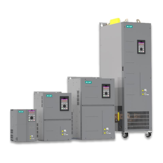
1. Product Information 1.2 Internal View of GT600 The drive can have either a plastic housing or a sheet metal housing, depending on the power rating. Figure 1-2 Internal view GT600-4T18.5GB to GT600-4T37GB (plastic housing) Fan cover Live indicator Cooling fan Never remove, install or wire the For replacement, see section 10.3. - Page 12 1. Product Information Figure 1-3 Internal view of GT600-4T45GB to GT600-4T160G (sheet metal housing) Cooling fan For replacement, see section 10.3. Barcode View the serial number and model of the drive here. Fixing pin of extension PG card See section 8.4.3. Cabling tray and fixing pin of ground cable of control board...
- Page 13 1. Product Information Figure 1-4 Internal view of GT600-4T200G to GT600-4T450G Protective cover of DC bus terminals Top hoist rings DC bus terminals Barcode View the serial number and model of the drive here. Nameplate Fixing pin of extension PG card See section 8.4.3.
- Page 14 1. Product Information Figure 1-5 Internal view of GT600-4T200G(-L) to GT600-4T450G(-L) Protective cover of DC bus terminals Top hoist rings DC bus terminals Barcode View the serial number and model of the drive here. Nameplate Fixing pin of extension PG card See section 8.4.3.
-
Page 15: Ratings
1. Product Information 1.3 Ratings Table 1-1 Ratings of GT600-4T18.5GB to Ratings of GT600-4T160G Voltage Class 380 to 480 VAC Model: GT600-4TxxxG(B 18.5 Frame Size [H1]: 915 Height [H] : 350 mm [H]: 400 mm [H1]: 540 mm [H1]: 576 mm Dimension Width [W]: 210 mm... - Page 16 1. Product Information GT600-4T200G(-L) to GT600-4T450G(-L) Table 1-2 Ratings of Voltage Class 380 to 480 VAC Model: GT600-4TxxxG(-L) Frame size Height [H1]: 1134 mm [H1]: 1284 mm [H1]: 1405 mm Dimension Width [W]: 300 mm [W]: 330 mm [W]: 340 mm (GT600- 4TxxxG) Depth...
-
Page 17: Technical Specifications
1. Product Information 1.4 Technical Specifications Table 1-3 Technical specifications of GT600 Item Description Standard Input frequency resolution Digital setting: 0.01 Hz functions Analog setting: Max. frequency x 0.025% Control mode Sensorless vector control (SVC) Feedback vector control (FVC) Voltage/Frequency (V/F) control Startup torque 0.25 Hz/150% (SVC) 0 Hz/180% (FVC) - Page 18 1. Product Information Item Description Virtual I/O Five groups of virtual digital input/outputs (DI/DO) support simple logic control. Timing control Time range: 0.0 to 6500.0 minutes Dual-motor switchover The drive have two groups of motor parameters and can control up to two motors. Multiple field buses The drive supports four field buses: Modbus-RTU...
- Page 19 1. Product Information Item Description Output terminals Standard Single high-speed pulse output terminal (open-collector) for a square-wave signal output in the frequency range 0 to 100 kHz Single digital output (DO) terminal Single relay output terminal Single analog output (AO) terminal that supports either a current output in the range 0 to 20 mA or a voltage output in the range 0 to 10 V.
-
Page 20: Rating
1. Product Information 1.5 De-rating The drive can be operated at above rated ambient temperature, altitude and default carrier frequency by de-rating drive capacity. ■ Carrier Frequency De-rating When carrier frequency of the drive is increased above default setting, you need to de-rate rated drive output current according to the following table: Power Carrier Frequency... - Page 21 1. Product Information 2. Mechanical Installation 2.1 Installation Environment .................. 20 2.2 Mounting Orientation and Clearance ............... 21 2.3 Mounting Dimensions ..................23 2.4 Installation Method and Procedures ..............26 2.5 Remove and Refit the Front Cover ..............40 - 19 -...
-
Page 22: Chapter 2 Mechanical Installation
2. Mechanical Installation Chapter 2 Mechanical Installation 2.1 Installation Environment Item Requirements Install the AC drive on a backplate, and ensure there is sufficient space around Cooling and ventilation the enclosure to allow for efficient heat dissipation. For details, see. Mounting Ensure the mounting location is: location... -
Page 23: Mounting Orientation And Clearance
2. Mechanical Installation 2.2 Mounting Orientation and Clearance ■ Mounting Orientation Always mount the AC drive in an upright position. ■ Mounting Clearance The mechanical clearance varies with the power ratings of the AC drive. Figure 2-1 Correct mounting clearance (Front view) (Side View) Clearance Requirements... - Page 24 2. Mechanical Installation The AC drive is designed with the cooling air flow direction from bottom to top. When installing several AC drives within a cabinet, it is necessary to line up the tops of the drives and allow cooling air clearance "A" as shown in Figure 2-3. Figure 2-3 Clearance for multi-drive installation Power Rating Clearance Requirements A ≥...
-
Page 25: Mounting Dimensions
Dimensions (mm) Weight Housing (kg) Type GT600-4T18.5GB Plastic Ø7 housing GT600-4T22GB GT600-4T30GB Plastic Ø7 17.5 housing GT600-4T37GB GT600-4T45GB Sheet metal Ø10 housing GT600 4T55GB GT600-4T75GB Sheet metal housing GT600-4T90G Ø10 51.5 GT600-4T110G GT600-4T132G Sheet metal Ø10 housing GT600-4T160G - 23 -... - Page 26 2. Mechanical Installation Figure 2-7 Overall dimensions of GT600-4T200G to GT600-4T400G 18.5GB to GT600-4T160G Table 2-2 Mounting dimensions of GT600 GT600 Model Dimensions (mm) Weight Housing (kg) Type GT600-4T200G Sheet metal 150 1035 1086 1134 300 360 500 Ø13 housing GT600-4T220G GT600-4T250G Sheet metal...
- Page 27 2. Mechanical Installation Figure 2-8 Overall dimensions of GT600-4T200G-L to GT600-4T450G-L GT600-4T200G-L to GT600-4T450G-L Table 2-3 Mounting dimensions of GT600 Model Dimensions (mm) Weight Housing (Kg) Type Sheet GT600-4T200G-L Φ13 metal 240 150 1035 424 1424 1472 300 GT600-4T220G-L housing Sheet GT600-4T250G-L Φ13...
-
Page 28: Installation Method And Procedures
2. Mechanical Installation 2.4 Installation Method and Procedures ■ Installation Method The drive units enclosed in a sheet-metal housing have weights of 35 kg or more. CAUTION These units have eye bolts that allow a mechanical hoist to support the weight of the unit during installation. - Page 29 2. Mechanical Installation Figure 2-9 Backplate-mounted installation of a plastic housing Figure 2-10 Backplate-mounted installation of a sheet metal housing Eye bolt Mounting holes 2.4.2 Through Hole Mounting There are three steps in process of preparing a through hole mounting for the AC drive. ■...
- Page 30 2. Mechanical Installation ● The AC drive enclosed in a sheet-metal housing have weights of CAUTION 35 kg or more. These units have eye bolts that allow a mechanical hoist to support the weight of the unit during installation. To prevent personal injury or damage to the equipment, you must fit and use these eye bolts to support the drive during installation.
- Page 31 2. Mechanical Installation ● Mounting hole diameter d ● Overall dimensions of the housing H and W ● Mark the backplate to identify the centers of the four mounting holes. ● Mark an outline for the cut-out by using the dimensions H and W. Ensure the cut-out is centred with respect to the mounting holes.
- Page 32 Through hole installation of a sheet metal housing ■ Through-hole Mounting Bracket Models Through-hole Mounting Bracket Model Applicable AC Drive Model Bracket Dimensions GT600-4T18.5GB Refer to GT600-AZJ-A1T5 GT600-4T22GB GT600-4T30GB GT600-AZJ-A1T6 GT600-4T37GB GT600-4T45GB GT600-AZJ-A1T7 GT600-4T55GB GT600-4T75GB GT600-4T90G GT600-AZJ-A1T8 GT600-4T110G GT600-4T132G GT600-AZJ-A1T9 GT600-4T160G - 30 -...
- Page 33 Models of GT600-4T200G(-L) to GT600-4T450G(-L) support mounting in cabinet only. ■ Ventilation Ventilation space must be considered when mounting drives of GT600-4T132G to GT600-4T450G. Figure 2-11 Cabinet without fan on the top Cabinet top air...
- Page 34 Cabinet Top Air Outlet (mm of Fans Volume Required by the (CFM) Top Fan (CFM) Air Inlet (mm GT600-4T132G 31809 50894 S = 0.942 x N x (Dout2-DHUB2) GT600-4T160G 31809 50894 In the preceding formula, N means the quantity of top fans,...
- Page 35 2. Mechanical Installation As shown in the following figure, an insulation barrier is required to prevent hot air circulating inside the cabinet. Figure 2-13 Insulation barrier in the cabinet Cabinet air outlet cover Isolation barrier GT600 ■ Precautions Nine-folding AL cabinet (PS cabinet) is recommended for installation of the drive. Before installing the AC drive, check whether fixing beams with fixing holes are mounted to the cabinet back correctly.
- Page 36 2. Mechanical Installation There are three steps of installing the AC drive in cabinet. Step 1: Get acquainted with cabinet layout. Figure 2-14 Recommended cabinet layout of GT600-4T350G to GT600-4T450 Cabinet ventilation top cover Ventilation airflow of Wind screen GT600 Transformer (from 380 V to 220 V) Breaker...
- Page 37 2. Mechanical Installation Step 2: Secure the fixing beam and reserve mounting holes The cross section of the nine-folding AL cabinet is shown in the following figure. Figure 2-15 Cross section of the nine-folding AL cabinet Nine-folding AL Fixing beam 800 mm 43.5 mm Fixing beam...
- Page 38 2. Mechanical Installation Prepare and install the bottom mounting bracket and guide rail. ● Take the bottom mounting bracket out and install it at the bottom of the nine-folding AL cabinet. If a non-nine-folding AL cabinet is used, drill mounting holes for the mounting bracket on site.
- Page 39 2. Mechanical Installation Step 3: Install the AC drive in the cabinet. ● Remove the front cover from the drive (refer to ). Then the handle is exposed. ● Arrange two persons to align castors of the drive to the guide rail. Figure 2-20 Align castors of the drive to the guide rail Guide rail (optional) ●...
- Page 40 2. Mechanical Installation Figure 2-22 Push-in completed ● Fix the AC drive to the beams on the back of the cabinet, as shown in the following figure. Cabinet frame Beams (on cabinet back) Mounting bracket Guide rail (optional) ● Check that installation of the drive is secure and remove the guide rail. - 38 -...
- Page 41 2. Mechanical Installation ● Ensure the four mounting holes on the back of the drive are connected to Note the beams securely. ● After push-in is completed, remove the baffle on the top of the drive. The baffle is used to prevent foreign objects such as screws from falling into the ventilation when mounting the drive in the cabinet.
-
Page 42: Remove And Refit The
2. Mechanical Installation 2.5 Remove and Refit the Front Cover You must remove the front cover before performing electrical installation ● Ensure the drive power-off time exceeds 10 minutes before removing the cover. WARNING ● Be careful when removing the front cover. A falling cover may cause personal injury. ■... - Page 43 2. Mechanical Installation ■ Remove and Refit the Front cover of a Sheet Metal Housing Removal Loosen four screws from the front cover, and then remove the front cover. Reattaching Locate and align the fixing hook at the top of the cover and secure the four screws. - 41 -...
- Page 44 2. Mechanical Installation ■ Remove and Refit the Front cover of GT600-4T200G(-L) to GT600-4T450G(-L) Removal Loosen six screws from the front cover, and then remove the front cover. Reattaching Locate and align the fixing hook at the top of the cover and secure the six screws. - 42 -...
- Page 45 2. Mechanical Installation 3. Electrical Installation 3.1 Typical System Connection ................44 3.2 Main Circuit Wiring.................... 45 3.3 Control Circuit Wiring ..................61 3.4 Wiring Checklist ....................70 - 43 -...
-
Page 46: Chapter 3 Electrical Installation
3. Electrical Installation Chapter 3 Electrical Installation 3.1 Typical System Connection The drive of 90 to 450 kW requires an optional external dynamic braking unit . The drive of 18.5 to 75 kW has built-in braking unit Brake unit Breaker Contactor Fuse J4 extension port +24V... -
Page 47: Main Circuit Wiring
3. Electrical Installation 3.2 Main Circuit Wiring 3.2.1 Main Circuit Terminals ■ Terminal Arrangement GT600-4T18.5GB to GT600-4T37GB GT600-4T45GB to GT600-4T160G POWER MOTOR GT600-4T200G to GT600-4T450G ■ Terminal Function Table 3-1 Description of input and output connections of the drive Terminal Name Description R, S, T... - Page 48 3. Electrical Installation ■ Cable Dimensions and Tightening Torque ● Data and models recommended in this section are for reference only. Note The user selected cable diameter must not be larger than the terminal width in the following figures. ● Selection of IEC cables is based on: –...
- Page 49 3. Electrical Installation Figure 3-2 Terminal dimensions of GT600-4T30GB/37GB 161.6 20.2 20.2 20.2 20.2 POWER MOTOR Table 3-3 Recommended cable dimensions and tightening torque of GT600-4T30GB/GT600-4T37GB AC Drive Model Rated Power Crimp Ground Crimp Tightening Screw Input Input/Output Terminal Cable Terminal Torque Spec.
- Page 50 3. Electrical Installation Figure 3-4 Terminal dimensions of GT600-4T75GB/GT600-4T90G/GT600-4T110G 30.6 M12 flat washer + spring washer + nut MOTOR POWER Table 3-5 Recommended cable dimensions and tightening torque of GT600-4T75GB/GT600- 4T90G/ GT600-4T110G AC Drive Model Rated Input/Output Crimp Ground Crimp Tightening Screw Input...
- Page 51 Figure 3-5 Terminal dimensions of GT600-4T132G/GT600-4T160G 42.5 POWER MOTOR M12 flat washer + spring washer + nut M10 combination screw Table 3-6 Recommended cable dimensions and tightening torque of GT600-4T132G/GT600-4T160G AC Drive Model Rated Power Crimp Ground Crimp Tightening Screw...
- Page 52 3. Electrical Installation Figure 3-6 Terminal dimensions of GT600-4T200G/220G (without output reactor) 236.5 2 13 48.5 31.5 3 13 108.5 108.5 8-M12 Figure 3-7 Terminal dimensions of GT600-4T200G-L/220G-L (with output reactor) 236.5 2- 13 48.5 31.5 3- 13 108.5 108.5 33 33 33 102.5 122.5...
- Page 53 3. Electrical Installation , the side entry copper bar can be removed if necessary. Terminal dimensions of main circuit terminals without side entry copper bar are shown below. Figure 3-8 Terminal dimensions of GT600-4T200G-L/220G-L (without side entry copper bar, without output reactor) 14-M12 236.5 2 13...
- Page 54 3. Electrical Installation Figure 3-10 Terminal dimensions of GT600-4T250G-L/280G-L (with output reactor) 192.5 2 13 3 13 193.5 8-M12 299.5 118.5 119.5 122.5 122.5 348.5 129.5 , the side entry copper bar can be removed if necessary. Terminal dimensions of main circuit terminals without side entry copper bar are shown below.
- Page 55 3. Electrical Installation Figure 3-12 Terminal dimensions of GT600-4T315G/450G (without output reactor) 2- 17 3- 17 8-M16 Figure 3-13 Terminal dimensions of GT600-4T315G-L/450G-L (with output reactor) 2- 17 3- 17 8-M16 111 130 130 In Figure 3-13, the side entry copper bar can be removed if necessary. Terminal dimensions of main circuit terminals without side entry copper bar are shown below.
- Page 56 3. Electrical Installation Figure 3-14 Terminal dimensions of GT600-4T315G-L/450G-L (without side entry copper bar, without output reactor) 2- 17 14-M16 Table 3-9 Recommended cable dimensions and tightening torque of GT600-4T315G(- L)/ 355G(-L)/400G(-L)/450G(-L) AC Drive Model Rated Input Power Input/ Crimp Ground Crimp Tightening...
- Page 57 3. Electrical Installation Model Dimensions (mm) Crimping Tool No. d2 (Min.) B (Max.) 14-8 16.0 32.8 14.5 10.5 YA-4 22-8 16.5 33.7 13.5 12.0 11.5 YA-5 22-12 13.0 22.0 42.5 19.5 12.0 11.5 YA-5 Table 3-11 Models and dimensions of the JST crimp terminal above Model Dimensions (mm) Crimping...
- Page 58 3. Electrical Installation 3.2.2 Main Circuit Cable Recommendations ■ Main Circuit Cable Selection K&R recommends symmetrical shielded cable as main circuit cable, which can reduce electromagnetic radiation of entire conductive system compared with four- conductor cable For more details, see descriptions in section ■...
- Page 59 3. Electrical Installation ■ Braking Resistor ● Fire risk! Fit overtemperature sensors or thermal overload relay to CAUTION the braking resistor, and use double insulated cables for the dynamic brake circuit to the brake resistors. ● Braking resistor terminals (+) and PB are only for the drive units up to 75 kW that are fitted with an internal braking unit.
- Page 60 Installation of the bracket is shown below. Table 3-13 Cable support bracket models Cable Support Bracket Model Applicable Drive Model GT600-4T18.5GB GT600-AZJ-A2T5 GT600-4T22GB GT600-4T30GB GT600-AZJ-A2T6 GT600-4T37GB GT600-4T45GB GT600-AZJ-A2T7 GT600-4T55GB GT600-4T75GB GT600-4T90G GT600-AZJ-A2T8 GT600-4T110G GT600-4T132G GT600-AZJ-A2T9 GT600-4T160G - 58 -...
- Page 61 3. Electrical Installation ● Cable specification and installation of all cables connected to the drive output U, V, W must comply with local safety regulations and relevant IEC standards. ● To avoid risk of equipment damage or operating faults, do not connect capacitor or surge absorber to the output side of the AC drive.
- Page 62 3. Electrical Installation ■ Main Circuit Cable Protection Add heat shrink tube to cable lug cooper tube and cable core part of main circuit cable and ensure the heat shrink tube completely covers the cable conductor part, as shown in the following figure.
-
Page 63: Control Circuit Wiring
3. Electrical Installation 3.3 Control Circuit Wiring 3.3.1 Control Circuit Terminals ■ Terminal Arrangement Figure 3-17 Control circuit terminal arrangement AO1 output selection: voltage output by default AI2 input selection: voltage input by default AI2 input impedance selection: 500Ωby default, 250Ω selectable - 61 -... - Page 64 3. Electrical Installation ■ Terminal Function Type Terminal Name Description Power +10V +10 V power Provides +10 V power supply to an supply supply external unit. Generally used to supply an external potentiometer of 1 to 5 kΩ Max. output current: 10 mA +24V +24 V power Provides +24 V power supply to an...
- Page 65 3. Electrical Installation Type Terminal Name Description Digital Digital output 1 Optically-coupled isolation, dual-polarity outputs open-collector output Output voltage range: 0 to 24 V Output current range: 0 to 50 mA. Note that CME and COM are internally insulated, but are shorted externally by a jumper.
- Page 66 3. Electrical Installation 3.3.2 Wiring Diagrams ■ Selection of Control Circuit Wirings All control wirings must be shielded. For different analog signals, use independent shielded cables and do not use the same shield. For digital signals, shielded twisted pair (STP) cable is recommended. STP cable ■...
- Page 67 3. Electrical Installation ■ Wiring of AI1 Analog signals at low levels can suffer from effects of external interference. To reduce this effect, it is important to use shielded cables shorter than 20 m long to carry analog signals. Figure 3-18 Wiring for analog input 1 <...
- Page 68 3. Electrical Installation ■ Wiring of DI1 to DI5 ● SINK wiring Figure 3-21 Wiring in SINK mode +24V +24V +VCC OP Signal Signal GT600 drive GT600 drive External External control board control board controller controller Internal 24 V power supply is applied. External 24 V power supply is applied.
- Page 69 3. Electrical Installation ● Source wiring Figure 3-23 Wiring in SOURCE mode +24V +VCC +24V Signal Signal GT600 drive External External GT600 drive control board controller controller control board Internal 24 V power supply is applied. External 24 V power supply is applied. If you intend to use internal power supply of the drive, remove the jumper between terminals +24V and OP.
- Page 70 3. Electrical Installation ■ Wiring of DO When digital output terminal must drive relay, it is necessary to install an absorption diode across relay coil. This diode prevents inductive switching transients causing damage to the DC 24V power supply. The absorption diode must have a forward current rating of 50 Figure 3-25 Wiring of digital output terminal +24V GT600...
- Page 71 3. Electrical Installation ■ Wiring of Relay To smooth peak voltage that results from cutting off power to inductive load (relay, contactor and motor), use a voltage dependent resistor (VDR) at the relay contact and add absorbing circuit to the inductive load, such as VDR, RC absorbing circuit or diode. Figure 3-27 Wiring of relay 220 VAC 24 VDC...
-
Page 72: Wiring Checklist
3. Electrical Installation 3.4 Wiring Checklist □ √ Item □ Check that you receive a correct model . □ Ensure correct peripheral devices (braking resistor, braking unit, AC reactor, filter and breaker) are used. □ Check optional cards. □ Check that mounting method and location meet the requirements. □... - Page 73 3. Electrical Installation 4. Operating Panel (Keypad & Display) 4.1 Introduction ....................... 72 4.2 Inbuilt LED Operating Panel ................72 - 71 -...
-
Page 74: Chapter 4 Operating Panel (Keypad & Display)
4. Operating Panel (Keypad & Display) Chapter 4 Operating Panel (Keypad & Display) 4.1 Introduction The AC drive has an inbuilt programming/operating panel with LED indicators and display. It allows you to operate function parameters and monitor/control system status. Remote/external operating panel is available as an option (refer to GT32NKE1 is an LED version with identical functions to the inbuilt version. - Page 75 4. Operating Panel (Keypad & Display) ■ Keys on LED Operating Panel Key Name Function ● Programming Enter or exit Level I menu. ● Return to the previous menu. ● Confirm Enter each level of menu interface. ENTER ● Confirm displayed parameter setting. ●...
- Page 76 4. Operating Panel (Keypad & Display) ■ Relevant Parameters for Operating Panel Setting Function Code Parameter Name Setting Range Default F7-01 MF.K key function 0: MF.K key disabled selection 1: Switchover from remote control (terminal or communication) to keypad control 2: Switchover between forward rotation and reverse rotation 3: Forward jog...
- Page 77 4. Operating Panel (Keypad & Display) ■ Unit Indicators There are three red unit indicators below the data display. These indicators operate individually or in pairs to show the units used to display data, as shown in Figure 4-2. Figure 4-2 Unit indicator explanation Indicator appearance Meaning Hz for frequency...
- Page 78 4. Operating Panel (Keypad & Display) 4.2.1 LED Operating Panel Menu Structure The drive operating panel has three levels of menu: 1. Level I - function parameter group 2. Level II - function parameter 3. Level III - function parameter value Figure 4-3 Structure of three levels of menu F0 28 F0 01...
- Page 79 4. Operating Panel (Keypad & Display) Operation procedure of the three levels of menu is as follows: Default screen Level I menu Return ENTER Return Level II menu ENTER ENTER ENTER Level III menu The following example shows how to modify F3-02 from 10.00 Hz to 15.00 Hz. Return ENTER ENTER...
- Page 80 4. Operating Panel (Keypad & Display) Press from a Level III menu to: ENTER 1. Save the parameter value you have set 2. Return to Level II menu, and then 3. Select the next function parameter. Press from a Level III menu to: 1.
- Page 81 4. Operating Panel (Keypad & Display) 4.2.2 Overall Arrangement of Function Parameters Function Code Group Description Standard Function Parameters F0 to FP Standard function code group Standard function parameters A0 to AC Advanced function code group AI/AO correction U0 to U3 RUNNING status function code group Display of basic parameters ■...
- Page 82 4. Operating Panel (Keypad & Display) 4.2.3 Function Parameter Operations ■ Viewing Function Parameters The drive provides three display modes for viewing parameters, described in Table 4-1. Table 4-1 Function parameter display modes Function Code Display Mode Parameter Name Setting Range Base mode Show all function parameters in sequence...
- Page 83 4. Operating Panel (Keypad & Display) The following table lists the often used parameters in the user-defined menu. Table 4-3 Often used parameters in the user-defined menu Function User-defined Function User-defined Parameter Name Parameter Name Code Function Code Code Function Code Motor 1 control Command source FE-00...
- Page 84 4. Operating Panel (Keypad & Display) 4.2.4 MF.K Key Function Function of the key on the LED operating panel can be set via function parameter F7- MF.K 01. You can switch over command source or frequency reference direction of the drive, and implement forward/reverse jog through this key in either STOP or RUNNING status.
- Page 85 4. Operating Panel (Keypad & Display) 4.2.6 Password Security The AC drive provides a security protection function that requires a user-defined password. Function parameter FP-00 controls this function. When FP-00 has the default value zero, it is not necessary to enter a password to program the AC drive.
- Page 86 5. Quick Setup 5.1 Get Familiar With Operating Panel ..............86 5.2 Setup Flowchart ....................87...
-
Page 88: Chapter 5 Quick Setup
5. Quick Setup Chapter 5 Quick Setup 5.1 Get Familiar With Operating Panel Before any commissioning work, you must go back to chapter 4 to get acquainted with the operating panel first. The operating panel allows you to monitor system operation, modify parameters and start or stop the AC drive. -
Page 89: Setup Flowchart
5. Quick Setup 5.2 Setup Flowchart START Para. Parameter name Default Commission Before power on Install and wire the drive Install and wire the drive as explained in chapters 1 to 3. Check wirings of power supply and AC drive outputs Restore parameters FP-01... - Page 90 5. Quick Setup CONTINUE Para. Parameter name Default Commission If an encoder is used Set encoder parameters F1-27 Encoder pulses per revolution 1024 1 to 65535ppr F1-28 Encoder type 0: ABZ incremental encoder 2: Resolver F1-30 A/B phase sequence of ABZ encoder 0: Forward 1: Reserve...
- Page 91 5. Quick Setup CONTINUE Para. Parameter name Default Commission Select control mode F0-01 Motor 1 control mode 0: SVC control 1: FVC control 2: V/F control Select frequency reference F0-03 Main frequency reference setting setting channel channel selection 0: Digital setting F0-08 (pressing can revise F0-08 easily, and the revised value won’t be cleared even after power off)
- Page 92 5. Quick Setup CONTINUE Para. Parameter name Default Commission If AI3 is frequency reference Set AI3 F4-23 AI curve 3 minimum input 0.00 0 V to F4-25; F4-24 Corresponding percentage of AI3 minimum input -100.0% to 100.0% F4-25 AI3 maximum input 10.00 F4-23 to 10.00 V F4-26...
- Page 93 5. Quick Setup CONTINUE Para. Parameter name Default Commission If any digital input is used Set DI function F4-00 DI1 function selection 0: No function 1: Forward RUN (FWD) 2: Reverse RUN (REV) 3: Three-wire control 4: Forward JOG (FJOG) 5: Reverse JOG (RJOG) 6: Terminal UP 7: Terminal DOWN...
- Page 94 5. Quick Setup CONTINUE Para. Parameter name Default Commission F4-00 DI1 function selection 33: External fault normally closed (NC) input 34: Frequency modification forbidden 35: PID action direction reverse 36: External STOP terminal 1 37: Command source switchover terminal 2 38: PID integral disabled 39: Switchover between main frequency source X and preset frequency...
- Page 95 5. Quick Setup CONTINUE Para. Parameter name Default Commission If any digital output is used Set DO function F5-00 FM output mode selection 0: FM terminal outputs pulses, the frequency of which represents the value of variable which is assigned by F5-06. 1: FM terminal outputs switch signal, the value of which represents the status of variable which is assigned by F5-01 F5-01 FM (switch signal) function...
- Page 96 5. Quick Setup CONTINUE Para. Parameter name Default Commission If any digital output is used Set DO function F5-01 FM (switch signal) function selection 26: Frequency 1 reached 27: Frequency 2 reached 28: Current 1 reached 29: Current 2 reached 30: Timing duration reached 31: AI1 input limit exceeded 32: Load lost...
- Page 97 5. Quick Setup CONTINUE Para. Parameter name Default Commission F5-04 DO1 function selection Setting range same as FM F5-05 Extension card DO2 function selection Setting range same as FM F5-06 FM (pulse signal) function selection 0: Running frequency 1: Set frequency 2: Output current 3: Output torque (absolute value) 4: Output power...
- Page 98 5. Quick Setup CONTINUE Para. Parameter name Default Commission if it is VF control Set VF parameters F3-00 V/F curve selection 0: Linear V/F 1: Multi-point V/F 2: Square V/F 3: 1.2-power V/F 4: 1.4-power V/F 6: 1.6-power V/F 8: 1.8-power V/F 9: Reserved 10: V/F complete separation 11: V/F half separation...
- Page 99 5. Quick Setup CONTINUE Para. Parameter name Default Commission if it is SVC or FVC control Adjust speed loop parameters F2-00 Speed loop proportional gain 1 To achieve better performance 0 to 100. F2-01 Speed loop integral time 1 0.01 to 10.00 Sec. F2-02 Switchover frequency 1 5.00...
- Page 100 5. Quick Setup - 98 -...
- Page 101 5. Quick Setup 6. Description of Parameters 6.1 Start/Stop Command Source ................100 6.2 Set Frequency Reference ................108 6.3 Start/Stop the AC Drive .................. 135 6.4 Motor Auto-tuning ................... 142 6.5 Control Performance ..................146 6.6 Protections ...................... 157 6.7 Monitoring .......................
-
Page 102: Chapter 6 Description Of Parameters
6. Description of Parameters Chapter 6 Description of Parameters 6.1 Start/Stop Command Source Three control methods are available: ● Operating panel (keypad & display) ● Terminal I/O control ● Serial communication You can select the required control mode in function parameter F0-02. Function Code Parameter Name Setting Range... - Page 103 6. Description of Parameters 6.1.1 Terminal I/O Control F4-11 defines the four terminal I/O control modes, in which the drive running is controlled by DI terminals. Function Code Parameter Name Setting Range Default F4-11 Terminal I/O control mode 0: Two-wire control mode 1 1: Two-wire control mode 2 2: Three-wire control mode 1 3: Three-wire control mode 2...
- Page 104 6. Description of Parameters The following example takes DI1, DI2 and DI3 to describe how to control the AC drive via DI terminals. ■ F4-11 = 0: Two-wire Control Mode 1 It is the most commonly used two-wire control mode. Allocate DI1 with forward run function and DI2 with reverse run function.
- Page 105 6. Description of Parameters Sequence diagrams of two-wire control mode 1 are shown in the following two figures. Figure 6-3 Two-wire 1 sequence (normal) SW1 (forward run command) SW2 (reverse run command) Motor speed Motor rotates in Motor rotates in Stop forward direction reverse direction...
- Page 106 6. Description of Parameters ■ F4-11 = 1: Two-wire Control Mode 2 In this mode, DI1 is RUN enabled terminal, and DI2 determines running direction. Allocate DI1 for RUN enabled function and DI2 for running direction. The parameters are set as below: Function Code Parameter Name Value...
- Page 107 6. Description of Parameters ■ F4-11 = 2: Three-wire Control Mode 1 In this mode, DI3 is three-wire control terminal. DI1 is set for forward run function and DI2 is set for reverse run function. The parameters are set as below: Function Code Parameter Name Value...
- Page 108 6. Description of Parameters ■ F4-11 = 3: Three-wire Control Mode 2 In this mode, DI3 is three-wire control command terminal. DI1 determines whether the RUN command is enabled and DI2 determines running direction. The parameters are set as below: Function Code Parameter Name Value...
- Page 109 6. Description of Parameters 6.1.2 Serial Communication We have the serial communications options, Modbus, Profibus-DP, CANlink and CANopen. F0-28 has to be set correctly to engage the selected serial communication card if Modbus, Profibus-DP or CANopen is selected. F0-28 need not be set if CANlink is selected. Function Code Parameter Name Setting Range Default...
-
Page 110: Set Frequency Reference
6. Description of Parameters 6.2 Set Frequency Reference The AC drive provides the following four methods to output the required frequency reference: ● Main frequency reference ● Auxiliary frequency reference ● Main & auxiliary calculation ● Command source + frequency reference setting channel 6.2.1 Set Main Frequency Reference Main frequency reference has nine setting channels. - Page 111 6. Description of Parameters Figure 6-12 Select main frequency reference setting channel Operation panel Digital setting Non-retentive F0-08 Digital setting Retentive Analog inputs 0 to 10 V 0 to 10 V F4-33 (Select AI curve) 4 to 20 mA Extended -10 to 10 V F0-03 Digital inputs...
- Page 112 6. Description of Parameters ■ Digital Setting (Non-retentive at Power Down) The initial value of frequency reference is F0-08 (Preset frequency). You can modify frequency reference by pressing on the operating panel (or using the UP/ DOWN function of input terminals). When the AC drive is powered on again, frequency reference continues from the value of F0-08.
- Page 113 6. Description of Parameters ■ Analog Input AI1 (0 to 10 V voltage input) AI2 (0 to 10 V voltage input or 0 to 20 mA current input, determined by setting of jumper AI3 (-10 to 10 V voltage input) Frequency reference is entered from an analog input (AI) terminal.
- Page 114 6. Description of Parameters F4-18 to F4-21 and F4-3 to F4-26 define AI curve 2 and AI curve 3, respectively. AI curve 2 and AI curve 3 have the same function and usage as AI curve 1 does. Refer to Figure 6-14 Set AI curve 2 Corresponding percentage...
- Page 115 6. Description of Parameters A6-00 to A6-15 define AI curve 4 and AI curve 5, which have the similar function of AI curve 1 to AI curve 3. AI curve 1 to AI curve 3 are linear correspondence and AI curve 4 and AI curve 5 are four-point correspondence.
- Page 116 6. Description of Parameters Step 2: Select a required curve for AI terminal. F4-33 selects curve of AI1, AI2 and AI3 from the five curves, respectively. Curve 1, curve 2 and curve 3 are 2-point curves, set in group F4. Curve 4 and curve 5 are 4-point curves, set in group A6.
- Page 117 6. Description of Parameters Example 2: On the condition that current input from AI2 is available, if 0 to 20 mA is input, it corresponds to voltage input of 0 to 10 V. If 4 to 20 mA is input, it corresponds to voltage input of 2 to 10 V.
- Page 118 6. Description of Parameters ■ Pulse Reference (DI5) Frequency reference is input by means of DI5 (high-speed pulse). Signal specification of pulse reference is 9 to 30 V (voltage range) and 0 to 100 kHz (frequency range). The corresponding value 100% of pulse reference corresponds to the value of F0-10 (max. frequency).
- Page 119 6. Description of Parameters ■ Multi-reference Multi-reference is a relative value and is a percentage of F0-10 (max. frequency). Whether the setting is positive or negative determines drive running direction. If negative, it indicates that the AC drive runs in reverse direction. Multiple frequency references are set in group FC, as listed in the following table.
- Page 120 6. Description of Parameters The four multi-reference terminals have 16 state combinations, corresponding to 16 references, as listed in the following table. Reference Setting Corresponding Pr. Reference 0 FC-00 Reference 1 FC-01 Reference 2 FC-02 Reference 3 FC-03 Reference 4 FC-04 Reference 5 FC-05...
- Page 121 6. Description of Parameters You can set holding time and acceleration/deceleration time of 16 frequency references in FC-18 to FC-49. Function Code Parameter Name Setting Range Default FC-18 Running time of simple PLC 0.0s (h) to 6553.5s (h) 0.0s (h) reference 0 FC-19 Acceleration/deceleration time of...
- Page 122 6. Description of Parameters Function Code Parameter Name Setting Range Default FC-41 Acceleration/deceleration time of 0 to 3 simple PLC reference 11 FC-42 Running time of simple PLC 0.0s (h) to 6553.5s (h) 0.0s (h) reference 12 FC-43 Acceleration/deceleration time of 0 to 3 simple PLC reference 12 FC-44...
- Page 123 6. Description of Parameters FC-50 sets running time unit in simple PLC mode. FC-51 selects the setting channel of reference 0. Function Code Parameter Name Setting Range Default FC-50 Time unit of simple 0: s (second) PLC running 1: h (hour) FC-51 Reference 0 source 0: Set by FC-00...
- Page 124 6. Description of Parameters Figure 6-22 Function block diagram of the PID control When FA-00 = 0 PID function Target FA-01 setting Kp(1 Td * S ) Motor Machine Ti * S Sensor Feedback When FA-00 = 1/2/3/4/5/6 PID function Target Kp(1 Td * S )
- Page 125 6. Description of Parameters Function Code Parameter Name Setting Range Default FA-00 PID reference setting 0: Set by FA-01 channel 1: AI1 2: AI2 3: AI3 4: Pulse reference (DI5) 5: Serial comms. 6: Multi-reference FA-01 PID digital setting 0.0% to 100.0% 50.0% FA-02 PID feedback setting...
- Page 126 6. Description of Parameters Function Code Parameter Name Setting Range Default FA-08 PID output limit in 0.00 Hz to max. frequency 2.00 Hz reverse direction FA-08: In some applications a high PID output in reverse direction may introduce adverse reactions and so a limit need to be applied". ●...
- Page 127 6. Description of Parameters Function Code Parameter Name Setting Range Default FA-15 Proportional gain Kp2 0.0 to 100.0 20.0 FA-16 Integral time Ti2 0.01s to 10.00s 2.00s FA-17 Differential time Td2 0.000s to 10.000s 0.000s FA-18 PID parameter 0: No switchover switchover condition 1: Switchover via DI 2: Auto switchover based on PID...
- Page 128 6. Description of Parameters Function Code Parameter Name Setting Range Default FA-25 PID integral property Units position: Integral separation 0: Disabled 1: Enabled Tens position: Whether to stop integral operation when the PID output reaches the limit 0: Continue integral operation 1: Stop integral operation FA-25 determines whether to enable integral separation function and whether to stop integral operation when PID output reaches limit.
- Page 129 6. Description of Parameters ■ Serial Comms. We have the serial communications options, Modbus, Profibus-DP, CANlink and CANopen. F0-28 has to be set correctly to engage the selected serial communication card if Modbus, Profibus-DP or CANopen is selected. F0-28 need not be set if CANlink is selected. Function Code Parameter Name Setting Range Default...
- Page 130 6. Description of Parameters To set frequency reference to 10000, host computer sends write command 01 06 10 00 27 10 97 36 (hexadecimal). In the command, ● 01H (settable): AC drive address ● 06H: write command ● 1000H: frequency reference address ●...
- Page 131 6. Description of Parameters 6.2.2 Setting Auxiliary Frequency Reference Auxiliary frequency reference has the same nine setting modes as main frequency reference does. F0-04 selects a proper channel to set auxiliary frequency reference. Function Code Parameter Name Setting Range Default F0-04 Auxiliary frequency 0: Digital setting (non-retentive at power down)
- Page 132 6. Description of Parameters Figure 6-27 select a proper channel to set auxiliary frequency reference Operation panel Digital setting Non-retentive F0-08 Digital setting Retentive Analog inputs 0 to 10 V 0 to 10 V F4-33 (Select AI curve) 4 to 20 mA Extended -10 to 10 V F0-04...
- Page 133 6. Description of Parameters 6.2.3 Main & Auxiliary Calculation You can set relationship between final frequency reference and main frequency reference & auxiliary frequency reference in F0-07. ● Use main frequency reference as final frequency reference. ● Use auxiliary frequency reference as final frequency reference. ●...
- Page 134 6. Description of Parameters Function Code Parameter Name Setting Range Default F0-07 Final frequency Units position: Frequency reference selection reference setting 0: Main frequency reference selection 1: Main and auxiliary calculation (based on tens position) 2: Switchover between main and auxiliary 3: Switchover between main and "main &...
- Page 135 6. Description of Parameters 6.2.4 Command Source + Frequency Reference Setting Channel It is possible to control final frequency reference through command source + frequency reference setting channel. Figure 6-29 Command source + main frequency reference setting channel Operating Units position panel Units position Tens position...
- Page 136 6. Description of Parameters 6.2.5 Frequency Reference Limit Function Code Parameter Name Setting Range Default F0-10 Max. frequency 50.00 to 500.00 Hz 50.00 Hz F0-11 0: Set by F0-12 Setting channel of frequency reference 1: AI1 upper limit 2: AI2 3: AI3 4: Pulse reference (DI5) 5: Communication reference...
-
Page 137: Start/Stop The Ac Drive
6. Description of Parameters 6.3 Start/Stop the AC Drive This section describes how to start/stop the AC drive. 6.3.1 Start Mode You can set start mode of the AC drive in F6-00, direct start, catching a spinning motor, pre- excited start and SVC quick start. Related function parameters are listed as follows: Function Code Parameter Name... - Page 138 6. Description of Parameters ■ F6-00 = 0: Direct Start It is applicable to most small-inertia loads, as shown in Figure 6-30 (1). Start frequency is applicable to drive equipment which requires startup torque, such as cement mixer, as shown in Figure 6-30 (2). The DC injection braking function is applicable to drive load such as elevator and crane, as shown in Figure 6-30 (3).
- Page 139 6. Description of Parameters ■ F6-00 = 1: Catching a Spinning Motor To catch a spinning motor, the AC drive detects speed and direction of spinning motor, and then starts to run from the spinning motor frequency. In this start mode, ensure that motor parameters in group F1 are set correctly. Figure 6-31 Catching a spinning motor Frequency F6-00 = 1: catching...
- Page 140 6. Description of Parameters 6.3.2 Stop Mode You can set the stop mode of the AC drive in F6-10, decelerate to stop and coast to stop. The related function parameters are listed as follows: Function Code Parameter Name Setting Range Default F6-10 Stop mode...
- Page 141 6. Description of Parameters F6-14: If it is set to 0, DC injection braking is disabled. Figure 6-32 Timing diagram of DC injection braking for stop F6-11 (DC injection braking 2 start Frequency) Output frequency RUN command Acceleration time Deceleration ti DC injection braking active F6-14 (DC injection...
- Page 142 6. Description of Parameters 6.3.3 Acceleration/Deceleration Time and S-curve Setting Acceleration time indicates time required by the AC drive to accelerate from 0 Hz to acceleration/ deceleration time base frequency (F0-25). Deceleration time indicates time required by the AC drive to decelerate from acceleration/ deceleration time base frequency (F0-25) to 0 Hz.
- Page 143 6. Description of Parameters The function parameters related acceleration/deceleration time are as follows: Function Code Parameter Name Setting Range Default F0-17 Acceleration time 1 0.00 to 650.00s (F0-19 = 2) Model dependent 0.0 to 6500.0s (F0-19 = 1) 0 to 65000s (F0-19 = 0) F0-18 Deceleration time 1 0.00 to 650.00s (F0-19 = 2)
-
Page 144: Motor Auto-Tuning
6. Description of Parameters 6.4 Motor Auto-tuning You can obtain parameters of controlled motor through motor auto-tuning. Motor auto-tuning methods are static auto-tuning 1, static auto-tuning 2 and dynamic auto-tuning. You can select a proper auto-tuning method in F1-37. Function Code Parameter Name Setting Range Default... - Page 145 6. Description of Parameters ■ F1-37 = 2: Dynamic Auto-tuning If motor has constant output characteristic and is used for high-accuracy application, disconnect motor from load and use dynamic auto-tuning. It is applicable to SVC or FVC mode. The dynamic auto-tuning process is as follows: Steps Description Step 1...
- Page 146 6. Description of Parameters Related parameters are described as follows: Function Code Parameter Name Setting Range Default F1-00 Motor type selection 0: Common asynchronous motor 1: Variable frequency asynchronous motor F1-01 Rated motor power 0.1 to 1000.0 kW Model dependent F1-02 Rated motor voltage 1 to 2000 V...
- Page 147 6. Description of Parameters Function Code Parameter Name Setting Range Default F1-27 Encoder pulses per 1 to 65535 1024 revolution F1-27 sets pulses per revolution (PPR) of encoder. In FVC mode, F1-27 must be set correctly. Otherwise, motor cannot run properly. Function Code Parameter Name Setting Range...
-
Page 148: Control Performance
6. Description of Parameters 6.5 Control Performance 6.5.1 V/F Curve ■ Linear, Multi-point and Square V/F Curve Function Code Parameter Name Setting Range Default F3-00 V/F curve setting 0, 2-9: Linear V/F 1: Multi-point V/F 10: V/F separation 11: Specific V/F separation F3-01 Torque boost 0.0%: automatic torque... - Page 149 6. Description of Parameters 2. User-defined Multi-point V/F curve Figure 6-37 User-defined Multi-point V/F curve Output voltage Rated voltage F3-08: V3 F3-06: V2 Rated frequency F3-04: V1 Output frequency F3-03 F3-05 F3-07 F3-03 to F3-08 define multi-point V/F curve. You must set multi-point V/F curve based on motor’s load characteristic. The three voltage points and frequency points must satisfy: V1 <...
- Page 150 6. Description of Parameters ■ V/F Separation Curve Function Code Parameter Name Setting Range Default F3-13 Voltage source for V/F 0: Set by F3-14 separation 1: AI1 2: AI2 3: AI3 4: Pulse reference (DI5) 5: Multi-reference 6: Simple PLC 7: PID reference 8: Serial comms.
- Page 151 6. Description of Parameters 6.5.2 Torque Boost The torque compensation function compensates for insufficient torque production at low frequency. Function Code Parameter Name Setting Range Default F3-01 Torque boost 0.0%: No torque boost Model dependent 0.1% to 30% F3-02 Cut-off frequency of 0.00 Hz to max.
- Page 152 6. Description of Parameters Function Code Parameter Name Setting Range Default F3-18 Current limit level 50% to 200% 150% F3-19 Current limit selection 0: Disabled 1: Enabled Current limit gain 0 to 100 F3-20 F3-21 Compensation factor of speed 50% to 200% multiplying current limit In high frequency area, motor drive current is small.
- Page 153 6. Description of Parameters 6.5.4 Voltage Limit and Braking Unit Applied Voltage When bus voltage rises above the value set in F3-22, the motor becomes regenerative. This function prevents overvoltage trips by adjusting the output frequency to extend deceleration time in this case.
- Page 154 6. Description of Parameters 6.5.5 Speed Loop Function Code Parameter Name Setting Range Default F2-00 Speed loop proportional gain 1 0 to 100 F2-01 Speed loop integral time 1 0.01 to 10.00s 0.50s F2-02 Switchover frequency 1 0.00 to F2-05 5.00 Hz F2-03 Speed loop proportional gain 2...
- Page 155 6. Description of Parameters 6.5.7 SVC Speed Feedback Stability Function Code Parameter Name Setting Range Default F2-07 Speed feedback filter time in 0.000s to 1.000s 0.015s This parameter takes effect only when F0-01 = 0. You can improve motor stability by increasing F2-07.
- Page 156 6. Description of Parameters Function Code Parameter Name Setting Range Default F2-11 Torque limit source in speed 0: F2-10 control (regenerative) 1: AI 2: AI2 3: AI3 4: Pulse reference (DI5) 5: Communication reference 6: Min. (AI1, AI2) 7: Max. (AI1, AI2) 8: F2-12 F2-12 Digital setting of torque...
- Page 157 6. Description of Parameters ■ Setting Torque Limit in Torque Control Function Code Parameter Name Setting Range Default A0-00 Speed/Torque control 0: Speed control selection 1: Torque control A0-01 Torque reference source in 0: Set by A0-03 torque control 1: AI1 2: AI2 3: AI3 4: Pulse reference (DI5)
- Page 158 6. Description of Parameters 6.5.8 Current Loop Function Code Parameter Name Setting Range Default F2-13 Excitation adjustment proportional gain 0 to 60000 2000 F2-14 Excitation adjustment integral gain 0 to 60000 1300 F2-15 Torque adjustment proportional gain 0 to 60000 2000 F2-16 Torque adjustment integral gain...
-
Page 159: Protections
6. Description of Parameters 6.6 Protections This section introduces functions on protecting the AC drive and motor. 6.6.1 Motor Overload Protection Function Code Parameter Name Setting Range Default F9-00 Motor overload protection 0: Disabled 1: Enabled F9-01 Motor overload protection 0.20 to 10.00 1.00 gain... - Page 160 6. Description of Parameters For example, application requires detect of Err11 when motor runs at 150% of rated motor current for two minutes. According to Figure 7-47, 150% (I) is in the range of 145% (I1) and 155% (I2). 145% corresponds to overload protection time 6 minutes (T1) and 145% corresponds to overload protection time 4 minutes (T2).
- Page 161 6. Description of Parameters 6.6.3 Fault Reset Function Code Parameter Name Setting Range Default F9-09 Auto reset times 0 to 20 This function parameter sets permissible times of auto fault reset. If reset times exceed the value set in this parameter, the AC drive will keep fault status. ●...
- Page 162 6. Description of Parameters Function Code Parameter Name Setting Range Default F9-49 Fault protection Units position: User-defined fault 1 (Err27) 00000 action selection 3 Tens position: User-defined fault 2 (Err28) Hundreds position: User-defined fault 3 (Err29) Thousands position: Load lost (Err30) 0: Coast to stop 1: Stop according to the stop mode 2: Continue to run at 7% of rated motor frequency...
- Page 163 6. Description of Parameters 6.6.5 Motor Overheat Protection Function Code Parameter Name Setting Range Default F9-56 Type of motor temperature 0: No temperature sensor sensor 1: PT100 2: PT1000 F9-57 Motor overheat protection 0° C to 200° C 110° C threshold F9-58 Motor overheat pre-warning...
- Page 164 6. Description of Parameters Function Code Parameter Name Setting Range Default F9-59 Power dip ride-through 0: Disabled function selection 1: Bus voltage constant control 2: Decelerate to stop F9-60 Threshold of power dip ride- 85% to 120% through function disabled F9-61 Judging time of bus voltage 0.1s to 10.0s...
- Page 165 6. Description of Parameters 6.6.8 Overspeed Protection Function Code Parameter Name Setting Range Default F9-67 Overspeed detection level 0.0% to 50.0% (max. frequency) 20.0% F9-68 Overspeed detection time 0.0s to 60.0s 1.0s These function parameters define motor overspeed detection that is effective only for vector control with speed sensor.
- Page 166 6. Description of Parameters 6.6.11 Output Overcurrent Protection This is to provide overcurrent protection for the AC drive. If the drive's output current is equal to or smaller than the value set in F8-36 and the duration exceeds the value set in F8-37, digital output terminal set for function 36 becomes on. Figure 6-47 Output current limit Output current F8-36...
-
Page 167: Monitoring
6. Description of Parameters 6.7 Monitoring The monitoring function enables you to view AC drive state in LED display area on the operation panel. You can monitor AC drive status in the following two ways: ● View F7-03, F7-04 and F7-05 by pressing on the operation panel. - Page 168 6. Description of Parameters Function Code Parameter Name Setting Range Default F7-03 LED display 0000 to FFFF running parameters 1 Running frequency 1 (Hz) Frequency reference (Hz) Bus voltage (V) Output voltage (V) Output current (A) Output power (kW) Output torque (%) DI state (V) 13 12 10 9...
- Page 169 6. Description of Parameters Function Code Parameter Name Setting Range Default F7-05 LED display stop 0000 to FFFF parameters Frequency reference (Hz) Bus voltage (V) DI state DO state AI1 voltage (V) AI2 voltage (V) AI3 voltage (V) Count value 11 10 9 Length value PLC stage...
- Page 170 6. Description of Parameters Function Code Parameter Name Display Range U0-07 DI state 0 to 32767 U0-07: It displays state of DI terminals. After the value is converted into a binary number, each bit corresponds to a DI. “1” indicates high level signal, and “0” indicates low level signal. The corresponding relationship between bits and DIs is described in the following table: Bit0 Bit1...
- Page 171 6. Description of Parameters Function Code Parameter Name Display Range U0-20 Remaining running time 0.0 to 6500.0 min U0-20: It displays remaining running time during drive timing running. Function Code Parameter Name Display Range U0-21 AI1 voltage before correction 0.00 to 10.57 V U0-22 AI2 voltage (V)/ current (mA) before 0.00 to 10.57 V...
- Page 172 6. Description of Parameters Function Code Parameter Name Display Range U0-38 ABZ position 0 to 65535 U0-38: It displays phase A and B pulse counting of current ABZ or UVW encoder. This value is four times the number of pulses that encoder runs. For example, if the display is 4000, actual number of pulses that encoder runs is 4000/4 = 1000.
- Page 173 6. Description of Parameters Function Code Parameter Name Display Range U0-44 DI set for function state display 2 U0-44: It displays whether DI terminals set for functions 41 to 59 are active. The display format is similar to U0-43. The 7-segment LEDs display functions 41–48, 49–56 and 57–59, respectively from right to left.
-
Page 174: Process Control
6. Description of Parameters 6.8 Process Control This section introduces three commonly used process control functions, the wobble function, fixed length and counting. 6.8.1 The Wobble Function The wobble function is applicable to industries such as textile and chemical fiber and winding and unwinding applications. - Page 175 6. Description of Parameters Related function parameters are as follows: Function Code Parameter Name Setting Range Default Fb-00 Wobble setting mode 0: Relative to the frequency reference 1: Relative to the max. frequency This function parameter selects base value of wobble amplitude. Function Code Parameter Name Setting Range...
- Page 176 6. Description of Parameters Figure 6-50 Fixed length control Any of F5-00 Allocate DO with the to F5-05 = 10 length reached function. Fb-05 Set length Allocate DI5 with the length F4-04 = 27 signal pulses counting function. DO outputs the length ≥...
- Page 177 6. Description of Parameters Figure 6-51 Counting function Any of F5-00 Allocate DO with the set to F5-05 = 8 count value reached function. Fb-08 Any of F4-04 Allocate DIx with the Set count value to F4-09 = 25 counter input function. ≥...
- Page 178 6. Description of Parameters 6.8.4 Motor 2 Parameters The drive supports driving two motors at different time. For the two motors, you can: ● Set motor nameplate parameters respectively ● Perform motor auto-tuning respectively ● Select V/F control or vector control respectively ●...
- Page 179 6. Description of Parameters Function Code Parameter Name Setting Range Default 0.01 to 655.35 (AC drive power ≤ 55 kW) A2-08 Leakage inductive Auto-tuning reactance parameter 0.001 to 65.535 (AC drive power > 55 kW) 0.1 to 6553.5 (AC drive power ≤ 55 kW) A2-09 Mutual inductive Auto-tuning...
- Page 180 6. Description of Parameters Figure 6-53 User programmable function (2) Control mode (units position AC drive control of A7-01) (See details in group F5) PLC program modified PLC controls (FM used as digital 0: output invalid PLC program digital output output) control (units position...
- Page 181 6. Description of Parameters ■ Parameter Settings of Controlling GT600 by PLC Programming Function 1. Set whether user programmable card is valid. Function Code Parameter Name Setting Range Default A7-00 User programmable function 0: Disabled selection 1: Enabled 2. Set AI3 and AO2 function on user programmable card. Function Code Parameter Name Setting Range...
- Page 182 6. Description of Parameters Function Code Parameter Name Setting Range Default A7-01 Control board output 00000 to 11111 00000 terminal control mode 0: AC drive control selection 1: User programmable card control Units position: FMR (FM used as digital output) Tens position: Relay (T/A-T/B-TC) Hundreds position: DO1 Thousands position: FMP (FM...
- Page 183 6. Description of Parameters 5. Set frequency reference When frequency reference setting channel is communication and A7-00 = 1 (user programmable card is enabled), frequency reference of the AC drive is determined by setting of A7-06. You can implement control of frequency reference of AC drive via PLC program by operating corresponding D component.
- Page 184 6. Description of Parameters 6.8.6 Master and Slave Control The master and slave control is designed for multi-drive application, where system is driven by multiple AC drives and motor shafts are coupled by gear, chain or conveyor belt. The load is averagely allocated to AC drives in master and slave control. The external control signal need be connected to the master only, and the master controls the slaves via communication.
- Page 185 6. Description of Parameters ■ Installation Figure 6-56 Connection of the master and slaves CANH CANL Slave Master Slave Slave MD38CAN1 MD38CAN1 MD38CAN1 MD38CAN1 GT600 GT600 GT600 GT600 DI COM TA TB TA TB TA TB You can use a relay for slave fault feedback or set tens position of A8-02 to Note 1 to send the salve fault information to the master via communication.
- Page 186 6. Description of Parameters For slave in torque control, perform the following settings. Note that only setting of F2- 10 can be modified, and setting of A0-03 must be consistent with that of F2-10 for the master. Function Code Parameter Name Setting Range Setting Fd-00...
- Page 187 6. Description of Parameters Function Parameter Name Setting Range Setting Code A0-01 Torque reference 0: Set by A0-03 source in torque 1: AI1 control 2: AI2 3: AI3 4: Pulse reference (DI5) 5: Serial comms. 6: MIN (AI1, AI2) 7: MAX (AI1, AI2) A0-03 -200.0% to 200.0% 130.0%...
- Page 188 6. Description of Parameters ● Flexible connection For the master in speed control, perform the following settings. Note that only the setting of F8-15 can be modified. Function Code Parameter Name Setting Range Setting Fd-00 Baud rate 0000 to 6039 Keep thousands position of this parameter to the same value for the master and...
- Page 189 6. Description of Parameters Function Code Parameter Name Setting Range Setting A8-02 Selection of 000 to 111 action of the slave 0: No in point-point communication 1: Yes Units position: whether to follow masters command Tens position: whether to send fault information to master when a fault occurs Hundreds position: whether to alarm when it becomes...
- Page 190 6. Description of Parameters ■ Droop Control The droop control function aims at balancing the load level of two motors that drive the same load. This function is required only when both master and slave are in speed control. A proper droop rate is gradually obtained during drive running. Therefore, do not set F8- 15 to a very large value.
- Page 191 6. Description of Parameters Function Code Parameter Name Setting Range Default A8-02 Selection of action of 0: No the slave in point-point 1: Yes communication Units positiion: whether to follow master's command Tens position: whether to send fault information to master when a fault occurs Hundreds position digit: whether to alarm when it becomes offline...
-
Page 192: Control Circuit Terminals
6. Description of Parameters 6.9 Control Circuit Terminals This section describes functions of DI, DO, virtual DI, virtual DO, AI and AO terminals. 6.9.1 Function of DI Terminals Function Code Parameter Name Setting Range Default F4-00 DI1 function selection 0 to 59 F4-01 DI2 function selection 0 to 59... - Page 193 6. Description of Parameters Value Function Description Multi-reference terminal 1 16 speeds or 16 other references can be implemented through combinations of 16 states of these four terminals. Multi-reference terminal 2 Multi-reference terminal 3 Multi-reference terminal 4 Terminal 1 for Totally four groups of acceleration/deceleration time can be acceleration/deceleration selected through combinations of four states of these two...
- Page 194 6. Description of Parameters Value Function Description External fault NC Once terminal set for this function becomes on, the AC drive input detects ERR15 and stops. Frequency When terminal set for this function becomes on, the AC drive modification enabled responds to frequency modification.
- Page 195 6. Description of Parameters Value Function Description Deceleration DC When terminal set for this function becomes on, the AC drive injection braking decelerates to DC injection braking 2 frequency threshold and then switches over to DC injection braking state. Clear running time When terminal set for this function becomes on, current running this time time of the AC drive is cleared.
- Page 196 6. Description of Parameters 6.9.2 Function of DO Terminals The drive provides a digital output (DO) terminal, an analog output (AO) terminal, a relay terminal and an FM terminal (either high-speed pulse output or open-collector output). Extra AO terminal (AO2), relay terminal (relay2) and DO terminal (DO2) are provided by the I/O extension card.
- Page 197 6. Description of Parameters Value Function Description Length reached Terminal set for this function becomes on when detected actual length exceeds value set in Fb-05. PLC cycle Terminal set for this function outputs a pulse signal with width of 250 completed ms when simple PLC completes one cycle.
- Page 198 6. Description of Parameters Value Function Description Reverse running Terminal set for this function becomes on when the AC drive runs in reverse direction. Zero current Refer to descriptions of IGBT temperature Terminal set for this function becomes on when heatsink reached temperature of AC Drive IGBT (F7-07) reaches IGBT temperature threshold (F8-47).
- Page 199 6. Description of Parameters 6.9.3 Function of VDI Terminals VDI terminals have the same functions as DI terminals do. They can be used for multi-functional digital inputs. Function Code Parameter Name Setting Range Default A1-00 VDI1 function selection 0 to 59 A1-01 VDI2 function selection 0 to 59...
- Page 200 6. Description of Parameters ● 1: Decided by A1-06 To enable the AC drive to automatically enter running status after power-on, perform the following settings: – Set A1-00 to 1 to set VDI1 for function 1 “Forward RUN (FWD)”. – Set A1-05 to xxx1 to determine VDI1 active state by state of A1-06.
- Page 201 6. Description of Parameters 6.9.5 Function of the AI Terminals The drive provides two AI terminals (AI1, AI2). An extra AI terminal (AI3) is provided by I/O extension card. Here use AI terminals as DI. When AI input voltage is higher than 7 V, AI is in high level state. When AI input voltage is lower than 3 V, AI is in low level state.
- Page 202 6. Description of Parameters 6.9.6 Function of the AO and Pulse Output Terminals The drive provides an AO terminal (AO1). An extra AO terminal (AO2) is provided by the I/O extension card (GT60IO1). Function Code Parameter Name Setting Range Default F5-00 FM terminal output mode 0: Pulse output (FMP)
- Page 203 6. Description of Parameters Function Code Parameter Name Setting Range Default F5-09 Max. FMP output frequency 0.01 to 100.00 kHz 50.00 kHz This function parameter sets maximum pulse output frequency when FM terminal is used for pulse output. Function Code Parameter Name Setting Range Default...
-
Page 204: Communication
6. Description of Parameters 6.10 Communication The drive support communication links, such as Modbus, PROFIBUS-DP, CANlink (always valid), or CANopen. You can monitor and control of the AC drive, for example, view or modify function parameters by using a host computer. Make sure to set communication parameters correctly. - Page 205 6. Description of Parameters Master Command Slave Response ADDR ADDR Parameter address high bits Parameter address high bits Parameter address low bits Parameter address low bits Number of function parameters Number of function parameters CRC high bits CRC high bits CRC low bits CRC low bits ■...
- Page 206 6. Description of Parameters 6.10.2 Read and Write State Parameters State parameters include monitoring parameters in group U (U0 to UF), drive fault information and drive running status. ● The highest 8 bits in communication of parameters in U0 to UF is 70 to 7F, while lowest eight bits indicate the hexadecimal number converted from SN in function code group.
- Page 207 6. Description of Parameters Sending message format of read operation is described as follows: CANopen Data Description 11-bit ID 0x600 + Node-ID The Node-ID of the equipment is set via the DIP switch. Remote frame sign "0" DATA0 Command code returned Correct: 0x4B Incorrect: 0x80 DATA1...
- Page 208 6. Description of Parameters 6.10.3 Write RUN Command When F0-02 = 2, you can write running command via communication on host computer, such as forward run, reverse run, forward jog, reverse jog and stop of the AC drive. Communication address and descriptions of running command are defined in the following table.
- Page 209 6. Description of Parameters Sending message and response message are described as follows: Sending Message Response Message Message ID Arbitration sign 1000 (binary) Message ID Arbitration sign 1000 (binary) 11050201H Q&A sign 1 (binary) 11050102H Q&A sign 1 (binary) Command code Command code Target address Target address...
- Page 210 6. Description of Parameters 6.10.4 Write Frequency/Torque Reference You can set frequency reference, torque limit, V/F separation voltage, PID reference and PID feedback via communication address 1000H. The data range is -10000 to 10000, corresponding to -100.00% to 100.00%. For example, to set main frequency reference to 8000 by using Modbus protocol, first set F0-03 = 9 and send write command 01 06 10 00 1F 40 84 CA.
- Page 211 6. Description of Parameters 6.10.5 Control of Digital Output (DO, Relay, FMR) If a digital output terminal is set for function 20: Communication setting, you can control digital output by using host computer. The communication address and command of digital outputs are defined in the following table. Related communication address and command are as follows: Communication Address Command Description...
-
Page 212: Auxiliary Function
6. Description of Parameters 6.11 Auxiliary Function 6.11.1 Jog Jog is used to test equipment. In jog running, F6-00 must be set to 0 (direct start) and F6-10 must be set to 0 (Decelerate to stop). Function Code Parameter Name Setting Range Default F0-25... - Page 213 6. Description of Parameters 6.11.2 Jump Frequency, FWD/REV Switchover Dead-zone Time, Reverse Run Prohibited ■ Jump Frequency The frequency jump function enables the AC drive to avoid mechanical resonance point of load. The drive can be set with two separate frequencies. If both are set to 0, the frequency jump function is disabled.
- Page 214 6. Description of Parameters ■ FWD/REV Switchover Dead-zone Time Figure 6-61 Forward/Reverse run switchover dead-zone time Output frequency (Hz) Forward run Reverse run Dead-zone time Function Code Parameter Name Setting Range Default F8-12 Forward/Reverse run 0.0s to 3000.0s 0.0s switchover dead-zone time ■...
- Page 215 6. Description of Parameters 6.11.3 Frequency Detection (FDT) This function sets detection values of output frequency and sets hysteresis level for the frequency detection function. Figure 6-63 Frequency detection Output frequency (Hz) Frequency Frequency detection level 1 hysteresis = F8-19 x F8-20 Time (t) (DO, relay) Time (t)
- Page 216 6. Description of Parameters 6.11.5 Acceleration/Deceleration Time Switchover This function selects acceleration/deceleration time according to running frequency range during drive running. This function is active only when motor 1 is selected and acceleration/ deceleration time is not switched over via external DI terminal. Figure 6-65 Acceleration/Deceleration time switchover Output frequency (Hz)
- Page 217 6. Description of Parameters 6.11.6 Frequency Reached Detection This function sets the detection value and detection width of frequency reached. Figure 6-66 Frequency reached detection Output frequency (Hz) Frequency detection width Frequency detection level Frequency detection width Time Frequency detection signal (DO or relay) The drive provides two groups of frequency detection parameters for the digital output functions 26 and 27.
- Page 218 6. Description of Parameters 6.11.8 Current Detection The drive provides two groups of current detection level and width. If output current of the AC drive reaches the width, digital output terminals set for functions 28 and 29 become on. Figure 6-68 Current detection Output current Current detection width Current detection level...
- Page 219 6. Description of Parameters 6.11.10 AI1 Input Voltage Upper/Lower Limit Function Code Parameter Name Setting Range Default F8-45 AI1 input voltage lower limit 0.00 V to F8-46 3.10 V F8-46 AI1 input voltage upper limit F8-45 to 10.00 V 6.80 V These two functiomn parameters indicate whether AI1 input voltage is in the setting range.
- Page 220 6. Description of Parameters Function Code Parameter Name Setting Range Default F8-49 Wakeup frequency Hibernating frequency (F8-51) to max. 0.00 Hz frequency (F0-10) F8-50 Wakeup delay time 0.0s to 6500.0s 0.0s F8-51 Hibernating frequency 0.00 Hz to wakeup frequency (F8-49) 0.00 Hz F8-52 Hibernating delay time...
- Page 221 6. Description of Parameters 7 . Interfaces and Communication 7.1 About Use of GT600 Terminals ................220 7.2 Serial Communication ..................223 7.3 About Multi-functional Extension Interfaces ........... 224 7.4 Definition of Communication Data Address ............ 225 7.5 Modbus Communication Protocol ..............228 - 219 -...
-
Page 222: Chapter 7 Interfaces And Communication
7. Interfaces and Communication Chapter 7 Interfaces and Communication 7.1 About Use of GT600 Terminals ■ Use of DI Terminals There are five digital inputs on control board, DI1 to DI5. There are five extra digital inputs on optional I/O extension board, DI6 to DI10,which are available to use if you have this option installed. - Page 223 7. Interfaces and Communication Terminal Corresponding Function Code Output Feature Description FM-CME F5-06 when F5-00 = 0 Transistor Able to output high-speed pulses 10 Hz to 100 KHz Drive capacity: 24 VDC, 50 mA F5-01 when F5-00 = 1 Transistor Drive capacity: 24 VDC, 50 mA TA-TB-TC F5-02...
- Page 224 7. Interfaces and Communication Terminal Input Signal Characteristic If J5 jumps to the "V" position, AO outputs voltage signal of 0 to 10 VDC. AO1-GND If J5 jumps to the "I" position, AO outputs current signal of 0 to 20 mA. AO2-GND It outputs voltage signal of 0 to 10 VDC or current signal of 0 to 20 mA.
-
Page 225: Serial Communication
7. Interfaces and Communication 7.2 Serial Communication You must install relevant extension card in the drive and set F0-28 correctly before you can use one of available serial communication protocols. The available serial communication protocols are: ● RS485 ● PROFIBUS-DP ●... -
Page 226: About Multi-Functional Extension Interfaces
7. Interfaces and Communication 7.3 About Multi-functional Extension Interfaces The following table lists extension cards that are available for use with the drive. Name Model Function Remark I/O extension card 1 GT60IO1 Provides the following: Available for all models. ● Five extra DI terminals. -
Page 227: Definition Of Communication Data Address
7. Interfaces and Communication 7.4 Definition of Communication Data Address The drive supports four communication protocols (Modbus-RTU, CANopen, CANlink, and PROFIBUS- DP). The user programmable card and point-to-point communication are derivation of CANlink protocol. Host computer can implement control such as monitoring and parameter viewing and modification on the AC drive through their protocols. - Page 228 7. Interfaces and Communication 7.4.2 Non-Parameter Data Non-parameter Status data (read- Group U (monitoring parameters), AC drive fault data only) information and AC drive running status Control parameters Control commands, communication setting values, DO (write-only) control, AO1 control, AO2 control, high-speed pulse (FMP) output control and parameter initialization ■...
- Page 229 7. Interfaces and Communication ● Communication reference Communication setting values include data set via communication such as frequency reference, torque limit, V/F separation voltage, PID reference and PID feedback. Communication address is 1000H. The range is -10000−10000 and corresponding value range is -100.00% to 100.00%. ●...
-
Page 230: Modbus Communication Protocol
7. Interfaces and Communication 7.5 Modbus Communication Protocol The drive provides RS485 communication interface and supports Modbus-RTU communication protocol so that the user can implement centralized control, such as setting running commands and function codes, and reading running status and fault information of the AC drive, by using a PC or PLC. This protocol defines content and format of transmitted messages during serial communication, including master polling (or broadcasting) format and master coding method (function code for the action, transmission data, and error check). - Page 231 7. Interfaces and Communication 7.5.3 Data Format The drive supports reading and writing of word-type parameters only. Reading command is 0x03 and writing command is 0x06. It does not support reading and writing of bytes or bits. The Modbu-RTU protocol communication data format of the drive is as follows: Master sending 1 Slave response 1 A Master sending 2...
- Page 232 7. Interfaces and Communication The frame format is described in the following table. Frame header (START) Greater than the 3.5-byte transmission idle time Slave address (ADR) Communication address : 1 to 247 0: Broadcast address Command code (CMD) 03:Read slave parameters 06: Write slave parameters Function code address (H) It is the internal parameter address of the AC drive, expressed...
- Page 233 7. Interfaces and Communication ■ CRC Check In Modbus-RTU mode, a message includes a CRC-based error-check field. The CRC field checks content of entire message. The CRC field is two bytes, containing a 16-bit binary value. The CRC field is calculated by transmitting device, and then added to message. The receiving device recalculates a CRC value after receiving message, and compares the calculated value with the CRC value in the received CRC field.
- Page 234 7. Interfaces and Communication 7.5.4 Definition of Communication Parameter Addresses ■ Read and Written Parameters Function parameters can be read and written (except those which cannot be changed because they are only for the factory use or for monitoring). Parameter group No. and parameter identifying No. are used to express parameter address.
- Page 235 7. Interfaces and Communication ■ Stop/RUN Parameters Para. Description Para. Description Address Address 1000 Communication setting value 1010 PID reference (Decimal): -10000 to 10000 1001 Running frequency 1011 PID feedback 1002 Bus voltage 1012 PLC process 1003 Output voltage 1013 Pulse input frequency, unit: 0.01 kHz 1004 Output current...
- Page 236 7. Interfaces and Communication Parameter lock password check If "8888H" is returned, it indicates that password check is passed. Password Address Password Content 1F00H ***** DO terminal control (write-only) Command Address Command Content 2001H BIT0: DO1 control BIT1: DO2 control BIT2: RELAY1 control BIT3: RELAY2 control BIT4: FMR control...
- Page 237 7. Interfaces and Communication AC drive fault description AC Drive AC Drive Fault Information Fault Address 8000 0011: Contactor fault 001E: Load lost 0012: Current detection fault 001F: PID feedback lost during running 0013: Motor auto-tuning fault 0028: Fast current limit timeout 0014: Encoder/PG card fault 0029: Motor switchover error 0015: Parameter read and write fault...
- Page 238 7. Interfaces and Communication Function Code Parameter Name Setting Range Default Fd-02 Local address 1 to 249 0: Broadcast address This parameter is used to set address of AC drive. This address is unique (except broadcast address), which is basis for point-to-point communication between host computer and AC drive. When local address is set to 0 (that is, broadcast address), AC drive can only receive and execute broadcast commands of host computer, but will not respond to host computer.
- Page 239 7. Interfaces and Communication 8. Peripherals and Options 8.1 MCCB, Fuse and Contactor ................241 8.2 Braking Unit and Braking Resistor ..............242 8.3 External Operating Panel ................246 8.4 Extension Cards ..................... 247 8.5 Through-hole Mounting Bracket ..............274 - 234 -...
-
Page 240: Chapter 8 Peripherals And Options
8. Peripherals and Options Chapter 8 Peripherals and Options Safety Information ● Do not connect or disconnect wirings while the power is on. Failure to comply will WARNING result in electric shock. ● Always keep breakers in OFF state at wiring or inspection. ●... - Page 241 8. Peripherals and Options When using the drive to drive asynchronous motor, a variety of electrical devices must be installed on both input and output sides to ensure system safety and stability. How to configure the drive AC drive (three-phase 380 to 480 V, 18.5 kW and above) to operate with the peripheral devices is shown as below: Three-phase AC power supply...
- Page 242 8. Peripherals and Options Description of Peripheral Electrical Devices Device Mounting Location Function Description Breaker Power input side MCCB: Cut off power supply when overcurrent occurs on downstream devices Leakage breaker: Provide protection against potentially leakage current during drive running to prevent electric shock and even a fire. Fuse AC drive input side Provide protection in case of short circuit.
-
Page 243: Mccb, Fuse And Contactor
Three-phase 380 to 480 V, 50/60 Hz GT600-4T18.5GB FWH-80B GT600-4T22GB FWH-100B GT600-4T30GB FWH-100B GT600-4T37GB FWH-125B GT600-4T45GB FWH-150B GT600-4T55GB FWH-200B GT600-4T75GB FWH-250A GT600-4T90G FWH-275A GT600-4T110G FWH-325A GT600-4T132G FWH-400A GT600-4T160G FWH-500A GT600-4T200G(-L) FWH-600A GT600-4T220G(-L) FWH-700A GT600-4T250G(-L) FWH-800A GT600-4T280G(-L) FWH-800A GT600-4T315G(-L) 1000 170M5016 GT600-4T355G(-L) 1000 170M5016 GT600-4T400G(-L) -
Page 244: Braking Unit And Braking Resistor
8. Peripherals and Options 8.2 Braking Unit and Braking Resistor ■ Selection of Resistance of Braking Resistor The AC drive transfers regenerative energy generated during braking of motor to external braking resistor. According to formula U x U/R = Pb: ●... - Page 245 440 VAC 11000 W, 10.5 Ω MDBUN-60-5T Input voltage > 10.5 x 2 440 VAC 13000 W, 6.8 Ω Input voltage ≤ GT600-4T132G MDBUN-90-T 6.2 x 2 440 VAC 13000 W, 8.8 Ω MDBUN-90-5T Input voltage > 7.0 x 2 440 VAC 16000 W, 6.3 Ω...
- Page 246 8. Peripherals and Options ● Minimum resistance supports operating condition with ED of 10% and longest Note time for single braking of 10s. ● Default initial braking voltage is 760 V. ● The preceding table is for a reference only. You can select resistance and power of braking resistor based on actual needs.
- Page 247 8. Peripherals and Options ■ Mounting Dimensions of MDBU Series Braking Unit 2-Φ6 Unit: mm For use and installation of MDBU series braking unit, refer to the MDBU Series Braking Unit User guide. ■ Mounting Dimensions of the AFE Unit The AC drive of K&R can be configured with the AFE unit, which can feedback energy produced during motor braking to the grid, saving braking unit and braking resistor can reducing heating pollution on surrounding environment.
-
Page 248: External Operating Panel
8. Peripherals and Options 8.3 External Operating Panel The GT32NKE1 is the external operating panel applicable to the drive. It adopts the LED display and has the same operation mode as the operating panel on the drive. For details, refer to The following figures show the physical appearance and mounting dimensions of the GT32NKE1. -
Page 249: Extension Cards
8. Peripherals and Options 8.4 Extension Cards The drive can implement field bus by connecting various extension cares. It supports different types of encoders and user programming function. This chapter describes installation and use of these extension cards. For more details, refer to the user guide that is delivered together with product. The following figure shows the mounting positions of these extension cards. - Page 250 8. Peripherals and Options The following table lists the extension cards that are available for use with the drive. Name Model Function Frequency Dividing Remark Coefficient MD38IO1 Provides the following: I/O extension Available for card 1 all models ● Five extra DI terminals. ●...
- Page 251 8. Peripherals and Options 8.4.1 Functional Extension Cards ■ Extension I/O Card (GT60IO1) GT60IO1 is developed by K&R and is designed for extension of input and output terminals of the drive. It has five digital input (DI) terminals, an analog input (AI) terminal, a relay output terminal, a digital output (DO) terminal and an analog output (AO) terminal.
- Page 252 8. Peripherals and Options Type Terminal Terminal Name Function Description Digital inputs DI6-OP1 Digital input 6 Optically-coupled isolation compatible with dual-polarity inputs DI7-OP1 Digital input 7 Input resistance: 2.4 kΩ DI8-OP1 Digital input 8 Voltage range for inputs: 9 to 30 V DI9-OP1 Digital input 9 DI10-OP1...
- Page 253 8. Peripherals and Options Table 8-2 Jumper descriptions of GT60IO1 Jumper Description Meaning Setting AO2 output selection: Voltage: V to 10 V voltage or current Current: 0 to 20 mA CAN terminal resistor Matching terminal matching selection resistor Not matching terminal resistor RS485 terminal 1 and 2 set to ON:...
- Page 254 8. Peripherals and Options ■ Extension Mini I/O Card (GT60IO2) GT60IO2 is simplified version of GT60IO1 and provides three DI terminals. DI6 DI7 DI8 COM OP2 +24V Table 8-3 Terminal descriptions of the GT60IO2 Type Terminal Terminal Name Function Description Power +24V-COM External +24V...
- Page 255 8. Peripherals and Options ■ Extension PC Card (GT60PC1) GT60PC1 card is designed with the PLC function, which enables the drive to have the PLC (user programmable) function. The card can read special variables of drive besides standard function codes and is more advantageous than combination of PLC and AC drive.
- Page 256 8. Peripherals and Options Type Terminal Terminal Name Function Description Analog input AI3-PGND Analog input 3 Optically-coupled isolation input, supporting differential voltage input, current input and temperature detection resistance input Input voltage range: -10 to 10 VDC Input current range: -20 to 20 mA Connect the PT100 or PT1000 temperature sensor Input mode determined by DIP switch...
- Page 257 8. Peripherals and Options Jumper Description Meaning Setting AO2 output Voltage selection: voltage or current Current RS485 terminal Matching the terminal resistor matching resistor selection Not matching the terminal resistor Run/Stop selection Stop OP1 connecting If DI connected in mode selection SINK mode, OP1 connected to +24V If DI connected in...
- Page 258 8. Peripherals and Options 8.4.2 Extension Communication Cards ■ Extension CANlink Card (GT60CAN1) GT60CAN1 is designed to connect the drive to high-speed CANlink bus. It complies with CANlink bus standard. CANlink is based on CAN bus and developed by K&R. It is an open communication protocol and equipments supporting this protocol can be connected to CANlink bus.
- Page 259 8. Peripherals and Options ● Use of CANlink bus The CANlink bus topology is shown as follows: CANlink bus CANH CANL 120Ω 120Ω terminal terminal resistor resistor CANH CANL CGND CANL CGND CANH CANL CGND CANH Set J2 to match Set J2 to match terminal resistor terminal resistor...
- Page 260 8. Peripherals and Options ■ Extension CANopen Card (GT60CAN2) GT60CAN2 is designed to connect the drive to high-speed CANopen bus. CANopen is an international field bus standard. Equipments supporting this protocol can be connected to the CANopen bus. GT60CAN2 supports the following five protocols: 1.
- Page 261 8. Peripherals and Options ● DIP switch setting Table 8-11 Descriptions of DIP switch setting Baud Rate Definition Address setting Definition DIP Switch 125Kbps Reserved 250Kbps … 500Kbps Baud CANopen address setting rate setting 1Mbps ● Indicators Table 8-12 Descriptions of indicators Indicator State Description...
- Page 262 8. Peripherals and Options ■ Extension RS485 Card (GT60TX1) GT60TX1 is specially designed to provide the drive with RS485 communication function. It adopts isolation scheme and electrical parameters conform to international standard. It helps to implement control of drive running and parameter setting through remote serial interface.
- Page 263 8. Peripherals and Options It is recommended to use an STP cable as the RS485 bus and use a twisted cable to connect 485+ and 485-. Connect a matching terminal resistor of 120 Ω respectively at both ends of the bus to prevent signal reflection. The RS485 bus allows connection of a maximum of 128 nodes and the distance of each node branch must be smaller than 3 m.
- Page 264 8. Peripherals and Options ● Terminal wiring – Terminal wiring if node has CGND GT60TX1 has three cables to connect 485+, 485- and CGND terminals respectively. Check that RS485 bus on site has these three cables and terminals are not connected reversely or wrongly. If a shielded cable is used, shield must also be connected to CGND.
- Page 265 8. Peripherals and Options ■ Extension PROFIBUS-DP Card (GT60DP2) GT60DP2, complying with international PROFIBUS field bus standard, is designed to connect the drive to PROFIBUS-DP bus. This card can improve communication efficiency and implement AC drive networking function. It enables the drive to be a slave in the bus, controller by the master.
- Page 266 8. Peripherals and Options ● DIP switch setting Profibus-DP Communication Slave Address Setting Slave DIP Switch Address Keep the Reserved OFF state (OFF: GT60DP2). … Reserved DP slave address setting ● Indicators Indicator Indication State Description D4 in red Power supply The drive is powered on.
- Page 267 8. Peripherals and Options ● PROFIBUS-DPbus topology RS485 bus 485+ 485- CGND 120Ω 120Ω terminal terminal resistor resistor 485+ 485- CGND 485+ 485- CGND 485+ 485- CGND Set J3 to match terminal resistor MD38TX1 MD38TX1 Master GT600 GT600 slave 1 slave N It is necessary to connect a matching terminal resistor to the end of PROFIBUS bus and set DIP switch properly.
- Page 268 8. Peripherals and Options 8.4.3 Extension PG Cards Specifications of extension PG cards are as follows: GT60PGMD GT60PG5D OA+ OA- OB+ OB- OZ+ OZ- GND OA OB OZ 1 2 3 4 5 CN3 CN4 D1 D2 D3 A B Z +5 CC CO A1 B1 V M M A+ A- B+ B- Z+ Z- COM PE...
- Page 269 8. Peripherals and Options GT60PG6 GT60PG6D GT60PG4 1 2 3 4 5 MD38PG4 Specification MD38PG6 Specification MD38PG6D Specification User interface DB9 female User interface DB9 female plug User interface DB9 female plug plug Pluggable Pluggable Pluggable Cable 26 to 21 AWG Cable 26 to 21 AWG Cable...
- Page 270 8. Peripherals and Options ■ Extension PG Card (GT60PGMD) Table 8-17 Terminal descriptions of GT60PGMD Terminal Function Description Encoder output signal A positive Encoder output signal A negative Encoder output signal B positive Encoder output signal B negative Encoder output signal Z positive Encoder output signal Z negative 5V/15V Encoder 5V/15V power supply...
- Page 271 8. Peripherals and Options ● Indicators Indicator Indication State Description D1/D2/D3 ON or The encoder has signal input. Encoder input signal indicator flash The encoder does not have signal input. Power indicator ON Normal. Power is not connected. LED1 Encoder input Input signal is slightly instable, which occurs signal quality when motor accelerates/decelerates or...
- Page 272 8. Peripherals and Options ■ Extension Resolver Card (GT60PG4) Table 8-18 Terminal descriptions of GT60PG4 Terminal Definition Function Description Pin Arrangement EXC1 Resolver excitation negative Resolver excitation positive COSLO Resolver feedback SIN positive SINLO SINLO Resolver feedback SIN negative Resolver feedback COS positive 6, 7, 8 Vacant internally EXC1...
- Page 273 8. Peripherals and Options ■ Extension Open-collector PG Card (GT60PG5D) Table 8-19 Terminal descriptions of GT60PG5D Terminal Function Description Encoder output signal A positive Encoder output signal B positive Encoder output signal Z positive Encoder 15V/100mA power supply CCM Power ground and frequency dividing output ground COM Power ground and frequency dividing output ground PG card frequency dividing output signal A (OC output, 0 to 24 V, 0 to 50 mA) PG card frequency dividing output signal B (OC output, 0 to 24 V, 0 to 50 mA)
- Page 274 8. Peripherals and Options ■ Extension Differential PG Card With Frequency Dividing (GT60PG6, GT60PG6D) Table 8-20 Terminal descriptions of GT60PG6 and GT60PG6D Terminal Definition Function Description Pin Arrangement Encoder output signal A positive Encoder output signal A negative Encoder output signal B positive Encoder output signal B negative Encoder output signal Z positive Null...
- Page 275 8. Peripherals and Options Wiring of GT60PG6/GT60PG6D is shown as follows: Shield Encoder card Encoder A+,B+,Z+ A+,B+,Z+ A-,B-,Z- Frequency A-,B-,Z- 26C32 Twisted dividing output pair A+,B+,Z+ A-,B-,Z- 26C31 ■ Grounding Shield of Extension Encoder Card On prerequisite that AC drive parameters are set properly, if PG card feedback speed or position is instable, it indicates that PG card suffers electromagnetic interference.
-
Page 276: Through-Hole Mounting Bracket
8. Peripherals and Options 8.5 Through-hole Mounting Bracket Figure 8-1 Bracket dimensions and hole size of GT600-4T18.5GB to GT600-4T22GB (unit: mm) 4-M5 screw Figure 8-2 Bracket dimensions and hole size of GT600-4T30GB to GT600-4T37GB (unit:mm) 4-M6 screw - 274 -... - Page 277 8. Peripherals and Options Figure 8-3 Bracket dimensions and hole size of GT600-4T45GB to GT600-4T55GB (unit:mm) 4-M7 screw Figure 8-4 Bracket dimensions and hole size of GT600-4T75GB to GT600-4T110G (unit:mm) 4-M8 screw - 275 -...
- Page 278 8. Peripherals and Options Figure 8-5 Bracket dimensions and hole size of GT600-4T132G to GT600-4T160G (unit: mm) 13.75 427.5 M8 screw Figure 8-6 Bracket dimensions and hole size of GT600-4T200G(-L) to GT600-4T220G(-L) (unit: mm) 35.5 580 (780) 32.5 42.5 22.5 6- 6 2-FH6 ×...
- Page 279 8. Peripherals and Options Figure 8-7 Bracket dimensions and hole size of GT600-4T250G(-L) to GT600-4T280G(-L) (unit: mm) 35.5 35.5 580 (780) 32.5 42.5 22.5 2-FH-M6 x 15 6 - 6 2 - 10 See details A 39.5 525 (725) 27.5 GT600-4T250G(-L) 30°...
- Page 280 8. Peripherals and Options - 278 -...
- Page 281 8. Peripherals and Options 9. Maintenance and Inspection 9.1 Daily Inspection ....................280 9.2 Periodic Inspection ..................282 9.3 Replacement of Wearing Components ............284 9.4 Storage ......................288 9.5 Warranty Agreement ..................288 - 279 -...
-
Page 282: Chapter 9 Maintenance And Inspection
9. Maintenance and Inspection Chapter 9 Maintenance and Inspection 9.1 Daily Inspection Safety Information ● Do not connect or disconnect wiring while the power is on. WARNING ● Disconnect all power and wait for several minutes. Do not touch any terminals before the capacitors have fully discharged. - Page 283 9. Maintenance and Inspection Influence of ambient temperature, humidity, dust and vibration will cause aging of components in the AC drive, which may cause potential faults or reduce the product life. Therefore, it is necessary to carry out routine and periodic maintenance. More frequent inspection will be required if it is used in harsh environments, such as: ●...
-
Page 284: Periodic Inspection
9. Maintenance and Inspection 9.2 Periodic Inspection 9.2.1 Periodic Inspection Items Always keep the AC drive clean. Clear away dusts especially metal powder on the surface of the AC drive, to prevent dust from entering the drive. Clear oil dirt from the cooling fan of the AC drive. - Page 285 9. Maintenance and Inspection 9.2.2 Insulation Test on Main Circuit ● Before measuring insulation resistance with megameter (500 VDC megameter Note recommended), disconnect the main circuit from the AC drive. ● Do not conduct the dielectric strength test. High voltage (> 500 V) test need not be performed again because it has been completed before delivery.
-
Page 286: Lifetime Of Fans And Electrolytic Dc Bus Capacitors
You can determine when to replace these parts according to the actual operating time. ■ Number of Fans on the Drive GT600 Model Number of Fans GT600-4T18.5GB GT600-4T22GB GT600-4T30GB GT600-4T37GB GT600-4T45GB GT600-4T55GB GT600-4T75GB GT600-4T90G GT600-4T110G GT600-4T132G GT600-4T160G GT600-4T200G GT600-4T220G GT600-4T250G GT600-4T280G GT600-4T315G GT600-4T355G GT600-4T400G GT600-4T450G - 284 -... - Page 287 9. Maintenance and Inspection ■ Removing and Installing the Fan of a Plastic Housing (GT600-4T18.5GB to GT600-4T37GB) Removal 1. Depress the fan cover hook and take the fan cover 2. Pull the fan upward and disconnect off the top of the drive. the pluggable connector of power cable.
- Page 288 9. Maintenance and Inspection ■ Removing and Installing the Fan of a Sheet Metal Housing (GT600-4T45GB to GT600-4T160G) Removal 1. Disconnect the fan cable 2. Remove the four screws 3. Remove the fan and fan cover from the drive from the drive. from the drive.
- Page 289 9. Maintenance and Inspection ■ Removing and Installing the Fan of GT600-4T200G(-L) to GT600-4T450G(-L) Removal 1. Disconnect the six screws and remove the front cover. 2. Disconnect the fan power cable connector from the drive. Each fan has a power cable connector.
-
Page 290: Storage
9. Maintenance and Inspection 9.4 Storage For storage of the AC drive, pay attention to the following three aspects: ● Pack the AC drive with original packing box provided by K&R. ● Do not place the AC drive in an area of moisture (95% H or more) or high temperature (over 60° C) or outdoors for long time. - Page 291 9. Maintenance and Inspection 10. Troubleshooting 10.1 Safety Information ..................290 10.2 Troubleshooting During Trial Run ..............291 10.3 Fault Display ....................293 10.4 Resetting Fault ..................... 294 10.5 Faults and Diagnostics ................. 295 10.6 Symptoms and Diagnostics ................302 - 288 -...
-
Page 292: Chapter 10 Troubleshooting
10. Troubleshooting Chapter 10 Troubleshooting 10.1 Safety Information Safety Information ● Do not disconnect the AC drive while power is on, and keep all breakers in OFF WARNING state. Failure to comply may result in electric shock. ● Make sure to ground the AC drive according to local laws and regulations. CAUTION Failure to comply may result in electric shock or a fire. -
Page 293: Troubleshooting During Trial Run
10. Troubleshooting 10.2 Troubleshooting During Trial Run This section provides solutions to oscillation, poor torque or speed response, or other problems that occur while performing a trial run. ■ Drive in Open-loop Vector Control (F0-01 = 0: Default value) The AC drive implements control of the motor speed and torque without an encoder for speed feedback. - Page 294 10. Troubleshooting ■ Drive in Feedback Vector Control (F0-01 = 1) It is applicable to the application with an encoder for speed feedback. In this mode, you need to set the encoder pulses per revolution (F1-27), the encoder type (F1-28) and the encoder direction (F1-30) correctly.
-
Page 295: Fault Display
10. Troubleshooting ■ Drive in V/F Control (F0-01 = 2) It is applicable to application without an encoder for speed feedback. You need to set rated motor voltage (F1-02) and rated motor frequency (F1-04) correctly. Problem Solutions Motor oscillation Increase the setting of F3-11 (V/F oscillation suppression gain) by 10 during running gradually. -
Page 296: Resetting Fault
10. Troubleshooting 10.4 Resetting Fault Stage Solution Remark After the Check operating panel for detailed information of View these information via F9-14 fault occurs recent three faults, such as fault type and frequency, to F9-44. current, bus voltage, DI/DO state, accumulative power-on time and accumulative running time at occurrence of the faults. -
Page 297: Faults And Diagnostics
10. Troubleshooting 10.5 Faults and Diagnostics Troubleshoot the fault according to the following table. If the fault cannot be eliminated, contact the agent or K&R Operating Panel Display Fault Name Overcurrent during acceleration Cause Possible Solution Ground fault or short circuit exists in Check whether short-circuit occurs on the motor, motor cable or the output circuit. - Page 298 10. Troubleshooting Operating Panel Display Fault Name Overcurrent at constant speed Cause Possible Solution Ground fault or short circuit exists in Check whether short-circuit occurs on the motor, motor cable or the output circuit. contactor. Control mode is SVC or FVC but Set motor parameters according to motor nameplate and perform motor auto-tuning is not performed.
- Page 299 10. Troubleshooting Operating Panel Display Fault Name Overvoltage at constant speed Cause Possible Solution Ensure that the voltage limit function is enabled (F3-23 = 1). The overvoltage stall prevention parameters are set improperly. The setting of voltage limit (F3-22) is too large. Adjust it between 700 V and 770 V.
- Page 300 10. Troubleshooting Operating Panel Display Fault Name Input phase loss Cause Possible Solution Input phase loss occurs. Eliminate faults in external circuitry. Drive board, lightning protection Contact the agent or Inovance. board, control board, or rectifier bridge is abnormal. Operating Panel Display Fault Name Output phase loss Cause...
- Page 301 10. Troubleshooting Operating Panel Display Fault Name Communication fault Cause Possible Solution Host computer is in abnormal state. Check the cable of host computer. Communication cable is abnormal. Check the communication cables. The serial port communication Set F0-28 of extension communication card correctly. protocol (F0-28) of extension communication card is set improperly.
- Page 302 10. Troubleshooting Operating Panel Display Fault Name EEPROM read-write fault Cause Possible Solution The EEPROM chip is damaged. Replace the main control board. Operating Panel Display Fault Name Short circuit to ground Cause Possible Solution Motor is short circuited to the ground. Replace cable or motor.
- Page 303 10. Troubleshooting Operating Panel Display Operating Panel Display Pulse-by-pulse current limit fault Cause Cause Load is too heavy or locked-rotor occurs on Reduce load or check motor and mechanical conditions. motor. The AC drive power class is small. Replace a drive of larger power class. Operating Panel Display Fault Name Motor switchover fault during running...
-
Page 304: Symptoms And Diagnostics
10. Troubleshooting 10.6 Symptoms and Diagnostics The following symptoms may occur during use of the AC drive. When these symptoms occur, perform simple analysis based on the following table. Operating Panel Display Fault Description There is no display while power-on. Cause Possible Solution The mains voltage is not input or too low. - Page 305 Appendix B Parameter Table 10. Troubleshooting Operating Panel Display Fault Description The motor does not rotate after the AC drive runs. Cause Possible Solution Check that wiring between AC drive and motor is normal. The wiring between the AC drive and motor is incorrect.
- Page 306 - 303 -...
- Page 307 10. Troubleshooting 11. Appendix Appendix A Standards Compliance ............306 A.1 CE Certification ....................306 A.2 UL Certification ....................329 Appendix B Parameter Table ................. 330 B.1 Introduction..................... 330 B.2 Standard Parameters ..................331 B.3 Monitoring Parameters ................... 353 - 304 -...
-
Page 308: Appendix A Standards Compliance
Appendix A Standards Compliance Appendix A Standards Compliance A.1 CE Certification A.1.1 CE Mark CE mark indicates compliance with European safety and environmental regulations. It is required for engaging in business and commerce in Europe. European standards include the Machinery Directive for machine manufacturers, the Low Voltage Directive for electronics manufacturers, and EMC guidelines for controlling noise. - Page 309 Rated Current (A) Model GT600-4T18.5GB FWH-80B GT600-4T22GB FWH-100B GT600-4T30GB FWH-100B GT600-4T37GB FWH-125B GT600-4T45GB FWH-150B GT600-4T55GB FWH-200B GT600-4T75GB FWH-250B GT600-4T90G FWH-275B GT600-4T110G FWH-325B GT600-4T132G FWH-400B GT600-4T160G FWH-500B GT600-4T200G FWH-600B GT600-4T220G FWH-700B GT600-4T250G FWH-800B GT600-4T280G FWH-800B GT600-4T315G 1000 170M5016 GT600-4T355G 1000 170M5016 GT600-4T400G 1400...
- Page 310 Appendix A Standards Compliance A.1.4 EMC Guidelines Compliance Electromagnetic compatibility (EMC) describes the ability of electronic and electrical devices or systems to work properly in the electromagnetic environment and not to generate electromagnetic interference that influences other local devices or systems. In other words, EMC includes two aspects: The electromagnetic interference generated by a device or system must be restricted within a certain limit;...
- Page 311 GT600-4T45GB FN 3258-100-35 DL-100EBK5 GT600-4T55GB FN 3258-130-35 DL-130EBK5 GT600-4T75GB FN 3258-180-40 DL-160EBK5 GT600-4T90G FN 3258-180-40 DL-200EBK5 GT600-4T110G FN 3270H-250-99 DL-250EBK5 GT600-4T132G FN 3359-250-28 DL-300EBK3 GT600-4T160G FN 3359-320-99 DL-400EBK3 GT600-4T200G(-L) FN 3359-400-99 DL-400EBK3 GT600-4T220G(-L) FN 3359-600-99 DL-600EBK3 GT600-4T250G(-L) FN 3359-600-99 DL-600EBK3...
- Page 312 Appendix A Standards Compliance – Mounting Dimensions Dimensions of Schaffner FN 3258 series 50-180A filter Unit: mm Rated Current (A) 190 40 160 180 20 29.5 250 45 220 235 25 22.5 29.5 270 50 240 255 30 39.5 310 50 280 295 30 37.5 250 85...
- Page 313 Appendix A Standards Compliance Dimensions of Schaffner FN 3270H series 150-2500A filter 150 to 250 A Unit: mm Unit: mm Dimensions of copper bar 320 to 1000 A - 311 - - 311 -...
- Page 314 Appendix A Standards Compliance Dimensions 150A 180A 250A 320A 400A 600A 800A 1000A 1600A 2500A (mm) Φ12 Φ12 Φ12 Φ12 Φ12 Φ12 Φ12 Φ12 Φ12 Φ14 M10 M10 M10 62.5 20 Φ10.5 Φ10.5 Φ10.5 Φ14 Φ14 Φ14 Φ14 - 312 -...
- Page 315 Appendix A Standards Compliance Dimensions of Jianli series 50-200A filter Unit: mm Filter Model (mm) DL-25EBK5 243 224 265 58 70 102 25 92 M6 58 M4 74 49 M6 6.4 x DL-35EBK5 DL-50EBK5 DL-65EBK5 DL-80EBK5 354 323 388 66 155 188 30 92 M8 62 M4 86 56 M8 6.4 x DL-100EBK5 DL-130EBK5 DL-160EBK5...
- Page 316 Appendix A Standards Compliance ● Simple EMC Filter A simple EMC filter is installed to prevent the surrounding interference and prevent the interference from the AC drive during running. Connect the simple EMC filter to ground reliably and ensure that the length of the cable connecting the drive and the filter is less than 30 cm.
- Page 317 Appendix A Standards Compliance ● Filter Capacitance Box and Ferrite Core In some applications, connect filter capacitance box and wind a ferrite core to remove some interference during drive running. Connect filter capacitance box to grounding terminal of the drive, and ground cable length cannot exceed 300 mm.
- Page 318 AC Input Reactor Model (K&R) GT600-4T18.5GB MD-ACL-50-0.28-4T-2% GT600-4T22GB MD-ACL-60-0.24-4T-2% GT600-4T30GB MD-ACL-80-0.17-4T-2% GT600-4T37GB MD-ACL-90-0.16-4T-2% GT600-4T45GB MD-ACL-120-0.12-4T-2% GT600-4T55GB MD-ACL-150-0.095-4T-2% GT600-4T75GB MD-ACL-200-0.07-4T-2% GT600-4T90G MMD-ACL-250-0.056-4T-2% GT600-4T110G MD-ACL-250-0.056-4T-2% GT600-4T132G MD-ACL-330-0.042-4T-2% GT600-4T160G MD-ACL-330-0.042-4T-2% GT600-4T200G(-L) MD-ACL-490-0.028-4T-2% GT600-4T220G(-L) MD-ACL-490-0.028-4T-2% GT600-4T250G(-L) MD-ACL-490-0.028-4T-2% GT600-4T280G(-L) MD-ACL-660-0.021-4T-2% GT600-4T315G(-L) MD-ACL-660-0.021-4T-2% GT600-4T355G(-L) MD-ACL-800-0.017-4T-2% GT600-4T400G(-L) MD-ACL-800-0.017-4T-2% GT600-4T450G(-L) MD-ACL-1000-0.014-4T-2%...
- Page 319 Appendix A Standards Compliance – Designation rules MD-ACL 0.28 Inovance AC Input Reactor Mark Voltage Drop Percentage Mark Rated Current Mark Rated Voltage 50 A Mark 0.28 380 V Indutance 0.28 mH – Dimensions Dimensions of AC input reactor of 50 to 60 A are shown as below: Rated Current Φ8.5 x 20 Φ6.4...
- Page 320 Appendix A Standards Compliance Dimensions of AC reactor of 90 to 120 A are shown as below: Rated Current 120± 1 Φ8.5 x 20 72± 2 188± 1 160 120± 1 Φ8.5 x 20 92± 2 Φ9 188± 1 160 78±...
- Page 321 Appendix A Standards Compliance Dimensions of AC reactor of 490 to 660 A are shown as below: Rated Current Φ12 x 20 122± 2 Φ12 320 106± 5 305 137± 10 198± 5 60± 5 243± 1 Φ12 x 20 137± 2 Φ12 320 106±...
- Page 322 GT600-4T22GB MD-OCL-60-0.12-4T-1% GT600-4T30GB MD-OCL-80-0.087-4T-1% GT600-4T37GB MD-OCL-90-0.078-4T-1% GT600-4T45GB MD-OCL-120-0.058-4T-1% GT600-4T55GB MD-OCL-150-0.047-4T-1% GT600-4T75GB MD-OCL-200-0.035-4T-1% GT600-4T90G MD-OCL-250-0.028-4T-1% GT600-4T110G MD-OCL-250-0.028-4T-1% GT600-4T132G MD-OCL-330-0.021-4T-1% GT600-4T160G MD-OCL-330-0.021-4T-1% ● Designation rules MD-OCL 0.14 Inovance AC Output Reactor Mark Voltage Drop Percentage Mark Rated Current Mark Rated Voltage 50 A 380 V 0.14...
- Page 323 Appendix A Standards Compliance ● Mounting dimensions Dimensions of AC output reactor of 50 to 120 A are shown as below: Rated Current (mm) 6 x 15 8.5 x 20 8.5 x 20 8.5 x 20 8.5 x 20 Dimensions of AC output reactor of 150 to 250 A are shown as below: - 320 - - 321 -...
- Page 324 Appendix A Standards Compliance Rated Current 11 x 18 11 x 18 11 x 18 Dimension of AC output reactor of 330 A Rated Current (mm) 11 x18 Note The dimensions of the AC input and output reactors are for reference only. - 323 -...
- Page 325 GT600-4T45GB RWK 305-90-KL 0.065 GT600-4T55GB RWK 305-110-KL 0.053 GT600-4T75GB RWK 305-156-KS 0.038 10.7 GT600-4T90G RWK 305-182-KS 0.032 GT600-4T110G RWK 305-230-KS 0.026 GT600-4T132G RWK 305-280-KS 0.021 GT600-4T160G RWK 305-330-KS 0.018 GT600-4T200G RWK 305-400-S 0.015 GT600-4T220G RWK 305-500-S 0.012 GT600-4T250G RWK 305-500-S 0.012...
- Page 326 Appendix A Standards Compliance 60-110A 124-330A Reactor Series (mm) (mm) (mm) (mm) (mm) (mm) 4 and 7.8A max.60 max.115 4.8 x 9 2.5 mm max.70 max.115 4.8 x 9 2.5 mm max.70 max.135 5 x 8 2.5 mm max.75 max.135 5 x 8 2.5 mm max.75...
- Page 327 Appendix A Standards Compliance ■ Common-mode Filter The common-mode filter is installed on output side (close to AC drive) to reduce bearing current and reduce interference on surrounding devices. The following figure shows installation of common-mode filter. U V W Cable length <...
- Page 328 Appendix A Standards Compliance A.1.7 Shielded Cable ■ Requirements for Shielded Cable Shielded cable must be used to satisfy EMC requirements of CE marking. Shielded cables are classified into three-conductor cable and four-conductor cable. If conductivity of cable shield is not sufficient, add an independent PE cable, or use a four-conductor cable, of which one phase conductor is PE cable.
- Page 329 Appendix A Standards Compliance A.1.8 Solutions to Current Leakage AC drive outputs high-speed pulse voltage, producing high-frequency leakage current during running of the drive. Each AC drive produces more than 100 mA leakage current. Therefore, it is necessary to select a residual current circuit-breaker with rated operating current of 100 mA above.
- Page 330 9. Maintenance and Inspection Appendix A Standards Compliance A.1.9 Solutions to Common EMC Interference Problems AC drive generates very strong interference. Although EMC measures are taken, interference may still exist due to improper cabling or grounding during use. When AC drive interferes with other devices, adopt the following solutions.
-
Page 331: Ul Certification
Appendix A Standards Compliance A.2 UL Certification If the AC drive has the cULus mark, it indicates that the product complies with the following North Americal Standards. Country Certification Name Standard U.S. UL508C Canada C22.2 No.14-13 Note that the motor overtemperature test is not asssessed by UL. - 329 -... -
Page 332: Appendix B Parameter Table
Appendix B Parameter Table Appendix B Parameter Table B.1 Introduction Password protection is available for use with the drive. If this protection has been enabled, Note you will need to know the user-defined password before you can edit the function codes described in this chapter. -
Page 333: Standard Parameters
Appendix B Parameter Table B.2 Standard Parameters Para. No. Param. Name Setting Range Default Property Page Group F0: Standard Parameters ● F0-00 G/P type display 1 and 2 Model dependent ★ F0-01 Motor 1 control mode 0 to 2 ☆ F0-02 Command source selection 0 to 2... - Page 334 Appendix B Parameter Table Para. No. Para. Name Setting Range Default Property Page ★ F0-22 Frequency reference resolution ☆ F0-23 Retentive of digital setting 0, 1 frequency upon stop ★ F0-24 Motor parameter group selection 0, 1 ★ F0-25 Acceleration/Deceleration time 0 to 2 base frequency ★...
- Page 335 Appendix B Parameter Table Para. No. Para. Name Setting Range Default Property Page ★ F1-30 A/B phase sequence of ABZ 0: Forward incremental encoder 1: Reserve ★ F1-34 Number of pole pairs of resolver 1 to 65535 ★ F1-36 Encoder wire-break fault detection s: No detection 0.0s time...
- Page 336 Appendix B Parameter Table Para. No. Para. Name Setting Range Default Property Page Group F3: V/F Control Parameters ★ F3-00 V/F curve setting 0, 2-9: Linear V/F 1: Multi-point V/F 10: V/F separation 11: Specific V/F separation ☆ F3-01 Torque boost 0.0%: automatic torque Model boost...
- Page 337 Appendix B Parameter Table Para. No. Para. Name Setting Range Default Property Page Group F4: Input Terminals ★ F4-00 DI1 function selection 0 to 59 ★ F4-01 DI2 function selection 0 to 59 ★ F4-02 DI3 function selection 0 to 59 ★...
- Page 338 Appendix B Parameter Table Para. No. Para. Name Setting Range Default Property Page F4-31 Corresponding percentage of -100.00% to 100.0% 100.0% pulse max. input Para. No. Para. Name Setting Range Default Property Page ☆ F4-32 Pulse filter time 0.00s to 10.00s 0.10s ☆...
- Page 339 Appendix B Parameter Table Para. No. Para. Name Setting Range Default Property Page ☆ F5-21 DO2 output delay 0.0s to 3600.0s 0.0s ☆ F5-22 DI active mode selection 1 00000 to 11111 00000 Para. No. Para. Name Setting Range Default Property Page Group F6: Start/Stop Control ☆...
- Page 340 Appendix B Parameter Table Para. No. Para. Name Setting Range Default Property Page ☆ F6-23 Overexcitation selection 0: Disabled 1: Enabled during deceleration 2: Enabled in the whole process ☆ F6-24 Overexcitation suppression 0% to 150% 100% current level ☆ F6-25 Overexcitation gain 1.00 to 2.50...
- Page 341 Appendix B Parameter Table Para. No. Para. Name Setting Range Default Property Page ☆ F8-12 Forward/Reverse run switchover 0.0s to 3000.0s 0.0s dead-zone time ☆ F8-13 Reverse RUN selection 0, 1 ☆ F8-14 Running mode when frequency 0 to 2 reference lower than frequency lower limit ☆...
- Page 342 Appendix B Parameter Table Para. No. Para. Name Setting Range Default Property Page ☆ F8-41 Detection width of current 2 0.0% to 300.0% (rated motor 0.0% current) ★ F8-42 Timing function 0, 1 ★ F8-43 Running time setting channel 0 to 3 ★...
- Page 343 Appendix B Parameter Table Para. No. Para. Name Setting Range Default Property Page ● F9-20 DI state upon 3rd fault ● F9-21 DO state upon 3rd fault ● F9-22 AC drive state upon 3rd fault ● F9-23 Power-on time upon 3rd fault ●...
- Page 344 Appendix B Parameter Table Para. No. Para. Name Setting Range Default Property Page ★ F9-62 Threshold of power dip ride- 60% to 100% through function enabled ☆ F9-63 Load lost protection 0: Disabled 1: Enabled ☆ F9-64 Load lost detection level 0.0% to 100.0% 10.0% ☆...
- Page 345 Appendix B Parameter Table Para. No. Para. Name Setting Range Default Property Page ☆ FA-20 PID error 2 for auto switchover FA-19 to 100.0% 80.0% ☆ FA-21 PID initial value 0.0% to 100.0% 0.0% ☆ FA-22 PID initial value active time 0.00s to 650.00s 0.00s ☆...
- Page 346 Appendix B Parameter Table Para. No. Para. Name Setting Range Default Property Page ☆ FC-18 Running time of simple PLC 0.0s (h) to 6553.5s (h) 0.0s (h) reference 0 ☆ FC-19 Acceleration/deceleration time of 0 to 3 simple PLC reference 0 ☆...
- Page 347 Appendix B Parameter Table Para. No. Para. Name Setting Range Default Property Page ☆ FC-43 Acceleration/deceleration time of 0 to 3 simple PLC reference 12 ☆ FC-44 Running time of simple PLC 0.0s (h) to 6553.5s (h) 0.0s (h) reference 13 ☆...
- Page 348 Appendix B Parameter Table Para. No. Para. Name Setting Range Default Property Page ☆ FE-10 User-defined parameter 10 Same as FE-00 F4-01 ☆ FE-11 User-defined parameter 11 Same as FE-00 F4-02 ☆ FE-12 User-defined parameter 12 Same as FE-00 F5-04 ☆...
- Page 349 Appendix B Parameter Table Para. No. Para. Name Setting Range Default Property Page ☆ A0-05 Forward max. frequency in torque 0.00 Hz to max. frequency 50.00 Hz control (F0-10) ☆ A0-06 Reverse max. frequency in torque 0.00 Hz to max. frequency 50.00 Hz control (F0-10)
- Page 350 Appendix B Parameter Table Para. No. Para. Name Setting Range Default Property Page ★ A2-04 Rated motor frequency 0.01 Hz to max. frequency Model dependent ★ A2-05 Rated motor speed 1 to 65535 rpm Model dependent 0.001 to 65.535 Ω (AC drive ★...
- Page 351 Appendix B Parameter Table Para. No. Para. Name Setting Range Default Property Page ☆ A2-45 Speed loop filter time constant 0.000s to 0.100s 0.000s ☆ A2-47 Torque limit source in speed 0 to 7 control ☆ A2-48 Digital setting of torque limit in 0.0% to 200.0% 150.0% speed control...
- Page 352 Appendix B Parameter Table Para. No. Para. Name Setting Range Default Property Page ★ A5-05 Voltage over modulation 100% to 110% 105% coefficient ☆ A5-06 Undervoltage threshold 210 to 420 V 350 V ★ A5-08 Dead-zone time adjustment 100% to 200% 150% ★...
- Page 353 Appendix B Parameter Table Para. No. Para. Name Setting Range Default Property Page ☆ A6-26 Jump point of AI2 input -100.0% to 100.0% 0.0% corresponding setting ☆ A6-27 Jump amplitude of AI2 input 0.0% to 100.0% 0.5% corresponding setting ☆ A6-28 Jump point of AI3 input -100.0% to 100.0%...
- Page 354 Appendix B Parameter Table Para. No. Para. Name Setting Range Default Property Page A8-11 Window width 0.20 to 10.00 Hz 0.50 Hz Group AC: AI/AO Correction ☆ AC-00 AI1 measured voltage 1 -10.00 to 10.000 V Factory- corrected ☆ AC-01 AI1 displayed voltage 1 -10.00 to 10.000 V Factory-...
-
Page 355: Monitoring Parameters
B.3 Monitoring Parameters Para. No. Para. Name Display Range Page Group U0: Monitoring Parameters U0-00 Running frequency 0.00 to 500.0 Hz U0-01 Frequency reference 0.00 to 500.0 Hz U0-02 Bus voltage 0.0 to 3000.0 V U0-03 Output voltage 0 to 1140 V U0-04 Output current 0.00 to 655.35 A... - Page 356 Para. No. Para. Name Display Range Page U0-31 Auxiliary frequency reference 0.00 to 500.00 Hz U0-32 Viewing any register address value U0-34 Motor temperature U0-35 Target torque -200.0% to 200.0% U0-36 Resolver position 0 to 4095 Para. No. Para. Name Display Range Page U0-37...
-
Page 357: Index
Control Circuit Terminals .......... 61 Control Circuit Terminals ........190 Control Circuit Wiring ........... 61 Control Performance .......... 146 Cooling Fan ............217 Counting ............. 174 Index Current Detection ..........216 Current Limit Control .......... 149 Current Loop ............156 About Use of GT600 Terminals ...... - Page 358 Motor 2 Parameters .......... 176 Function Parameter Operations ......80 Functional Extension Cards ....... 249 Fuse ..............241 FWD/REV Switchover Dead-zone Time ..... 211 Get Familiar With Operating Panel ...... 86 Hibernating and Wakeup........217 IGBT Temperature ..........217 Improving Field Weakening Area Performance .156 Inbuilt LED Operating Panel ........
- Page 359 Peripheral EMC Devices ........309 Motor Auto- Peripherals and Options ........238 Non-Parameter Data .......... 226 tuning ..............142 Phase Loss Protection ........158 Motor Please Read This Important Information ....1 Overheat Operating Panel (Keypad & Display) ....72 Protection ............
- Page 360 Replacement of Wearing Components ....284 Through-hole Mounting Bracket ......274 Resetting Fault ........... 294 Timing Function ..........216 Reverse Run Prohibited ........211 Torque Boost ............149 Running Mode When Frequency Reference Below Troubleshooting ..........290 Lower Limit ............134 Troubleshooting During Trial Run.......
-
Page 361: Revison History
Revision History Date Version Change Description It corresponds to V1.1 of the GT600 High-performance AC drive User guide in Nov 2015 V0.0 Chinese version. Add power rating models of GT600-4T200G(-L) to GT600-4T450G(-L). Apr 2016 Firmware version: F7-10 = U76.57, F7-11 = U77.57 Nov 2016 Modified Approvals, designation rule and nameplate, Table 1-1 and Table 1-2.
Need help?
Do you have a question about the GT600-4T132G and is the answer not in the manual?
Questions and answers