Table of Contents
Advertisement
Quick Links
Advertisement
Table of Contents

Related Manuals for Magellan ProFlex 500


Summary of Contents for Magellan ProFlex 500
- Page 1 ProFlex ™ Reference Manual Preliminary...
- Page 2 U-Link transmit- a Class A digital device, pursuant to Part 15 of the ter to the ProFlex 500 receiver via a 7-pin connector, FCC Rules. These limits are designed to provide rea- and to the power battery.
- Page 3 (3) installations or defects re- sulting from installation; (4) any damage caused by In the event of a defect, Magellan Navigation will, at (i) shipping, misuse, abuse, negligence, tampering, its option, repair or replace the hardware product or improper use;...
- Page 4 APPLIES ONLY TO THE ORIGINAL PURCHASER OF (2) batteries; THIS PRODUCT. (3) finishes; In the event of a defect, Magellan Navigation will, at (4) installations or defects resulting from installa- its option, repair or replace the hardware product tion; with no charge to the purchaser for parts or labor. The...
- Page 5 For further information concerning this limited war- ranty, please call or write: Magellan Navigation SAS - ZAC La Fleuriaye - BP 433 - 44474 Carquefou Cedex - France. Phone: +33 (0)2 28 09 38 00, Fax: +33 (0)2 28 09...
- Page 6 • Use in Land Surveying applications with ProFlex 500 only. If in doubt with what the a field terminal run by FAST Survey (Ch ProFlex 500 really does in such or such cir-...
-
Page 7: Table Of Contents
Table of Contents Chapter 1. Introduction ..............1 What is ProFlex 500? ..............1 System Components Overview............2 Equipment Description & Basic Functions ........7 Display Screens ...............13 Charging Batteries Before Use ...........17 Specifications ................19 Firmware Options ..............23 Port Pinouts................23 Land Surveying in Backpack Configuration with FAST Survey Chapter 2. - Page 8 Continuous Kinematic Survey ............82 ProFlex 500 Used as a GNSS Sensor Chapter 7. Marine Surveying & Machine Guidance ......85 Short Introduction to Controlling ProFlex 500 Through $PASHS Commands ............85 Chapter 8. Using Serial Commands ..........87 Introduction to Serial Commands ..........87 Applying Commands Through Serial Port or Bluetooth....88...
- Page 9 GLO: GLONASS Tracking ............136 LTZ: Time Zone..............137 MDM,DAL: Dialing and Hanging up..........138 MDM,INI: Initializing the Modem..........139 MDM,OFF: Powering Off the Internal Modem ......140 MDM,ON: Powering On the Internal Modem......141 MDM,PAR: Setting the Modem Parameters .......142 MDP: Setting Port A to RS232 or RS422 .........144 MEM: Selecting Memory Device Used ........145 MWD: Setting the Modem Timeout...........146 NME: Enabling/Disabling NMEA Messages .......147...
- Page 10 ANH: Antenna Height .............185 ANP: Antenna Parameters ............185 ANR: Antenna Reduction Mode ..........187 ANT: Antenna Height..............188 ATM: ATOM Data Parameters ..........189 ATO: ATOM Message Parameters ..........191 BAS: Differential Data Type.............193 BEEP: Beeper State..............194 BTH: Bluetooth Settings ............195 CMR,MSI: CMR Message Status ..........196 CPD,AFP: Ambiguity Fixing Parameter........197 CPD,ANT: Base Antenna Height..........198 CPD,FST: Fast RTK Output Mode..........199...
- Page 11 PHE: Active Edge of Event Marker Pulse........237 POS: Computed Position Data ..........238 PPS: PPS Settings ..............239 PRT: Baud Rate Settings ............239 PTT: PPS Time Tag ..............241 PWR: Power Status..............242 RAW: Raw Data Logging Settings ..........243 RDP,CHT: Radio Channel Table ..........245 RDP,PAR: Radio Parameters ...........246 RDP,TYP: Radio Type Used .............249 REC: Raw Data Recording Status ..........250...
- Page 12 Choosing a Location for the Base ..........304 Initialization ................306 GNSS Antennas and Antenna Heights ........313 General Considerations on Accuracy .........317 Ellipsoidal Height and Elevation ..........321 Localization ................323 Chapter 13. RTK Implementation........... 327 Data Link ................327 RTK Correction Data Formats ..........336 RTK Position Output...............338 Chapter 14.
-
Page 13: Chapter 1. Introduction
Learning to put these tools to work quickly and efficiently will be the focus of the present manual. ProFlex 500 is a flexible, rugged and high-performance GNSS receiver integrating the best of today’s technologies, including the exclusive Magellan BLADE™ algorithms and multi-constellation (GPS+GLONASS+SBAS) capabilities. -
Page 14: System Components Overview
Makes ProFlex 500 a USB device. Ethernet adaptor cable 702426 Serial data cable 700461 AC/DC Power Supply Kit (includes external AC adapter, battery charger and cable extension for 802064 powering ProFlex 500 directly from the AC adapter) ProFlex 500 User Documentation CD 501510... - Page 15 Optional Transmitter Kits Item Part Number Picture 800986-10 (0.5/4 W, 410-430 MHz) 800986-30 (0.5/4 W, 430-450 MHz) Magellan U-Link 800986-50 (0.5/4 W, 450-470 MHz) radio transmitter, Each P/N includes a whip antenna, an 12.5-kHz channel Picture of antenna bracket, a Y-shaped data/power...
- Page 16 Introduction Optional Receiver Kits Item Part Number Picture 802087-10 (410-430 MHz) PDLRXO receiver kit, 12.5-kHz 802087-30 (430-450 MHz) (Internal part) channel bandwidth 802087-50 (450-470 MHz) 802087-15 (410-430 MHz) PDLRXO receiver kit, 25-kHz 802087-35 (430-450 MHz) (Internal part) channel bandwidth 802087-55 (450-470 MHz) Backpack Kit Option Item Part Number...
- Page 17 700461 TNC/TNC coaxial cable, 10 meters 700439 External DC Power Cable for Receiver 730477B USB Device Cable. 702103 Makes ProFlex 500 a USB host. UHF Accessory Kit (30 meters) Item Part Number Picture TNC-m/TNC-m, KX15 coaxial cable, 1 meter, C5050156...
- Page 18 Introduction UHF Accessory Kit (10 meters) Item Part Number Picture TNC-m/TNC-m, KX15 coaxial cable, 1 meter, C5050156 + N-f/TNC-f coaxial adaptor C5050216 N-m/N-m, 50-ohm, KX13 coaxial cable, P0101131 10 meters UHF antenna, 3 dB (CXL70-3 C/L) C3310145...
-
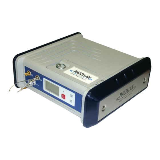
Page 19: Equipment Description & Basic Functions
A coaxial female connector (SMA type) allowing you to connect a cellular antenna. A cellular antenna is required when the ProFlex 500 receives RTK or differential corrections data via its internal cellular modem (GSM). Take care not to swap the Bluetooth antenna and the cellular antenna. - Page 20 Introduction 2. For a USB device allowing ProFlex 500 to be seen as a disk from the computer connected to this port. In this configuration, files can be transferred between the ProFlex 500’s internal memory and the computer using the USB cable provided (P/N 702104).
- Page 21 DC Power Input A Fischer, three-contact, female connector [1] allowing the ProFlex 500 to be powered from either the provided AC adapter (connect the cable extension between ProFlex 500 and the end of the AC adapter output cable), or an external 9- to 36-V DC power source through cable P/N 730477 (cf.
- Page 22 ProFlex 500 has been fitted with a radio module. Ethernet Port A Fischer, seven-contact female connector [7] allowing you to connect the ProFlex 500 to a local network (LAN). Through this connector, you may remotely control and monitor the ProFlex 500 from any computer connected to the Internet.
- Page 23 It is a standard model used in many camcorders. The battery is housed in a battery compartment accessible from above the ProFlex 500. The compartment door can be opened by lifting and then turning the quarter-turn finger screw counter-clockwise.
- Page 24 Introduction Special Button • With the ProFlex 500 OFF, pressing the Power, Log and Scroll buttons simultaneously for a few seconds will Combinations restore all the factory settings. Always use this combination after changing the radio module. This allows the receiver to recognize the new module.
-
Page 25: Display Screens
If you press the Scroll button several times, you will see the following displays successively. Power-On Screen When you power on the receiver, the Magellan Professional logo appears on the screen. It is displayed until the receiver has completed its auto-test (this takes about 30 seconds). - Page 26 Introduction • Number of satellites used [4]: Number of satellites used in the position processing, regardless of the current position solution status. • : Data link icon [5]. This icon is displayed only when corrections are received and at least a float solution is available.
- Page 27 Introduction Icon Definition Blinking icon: GSM module turned on. Indicates signal strength received at current location. The higher the number of bars, the better the signal. Fixed icon: GSM module turned on and initialized (ready for a connection). Indicates signal strength received at current location. GSM module on line.
- Page 28 Introduction • First line: Total space occupied by the files currently stored in the internal memory. • Second line: Nominal size of the internal memory. • Third line: Total space occupied by the files currently stored on the USB mass storage device. •...
-
Page 29: Charging Batteries Before Use
Introduction Charging Batteries Before Use Make sure the battery is fully charged for each ProFlex 500 you will be using in the field. Follow the instructions below to charge a battery. Removing the Unless the battery has already been taken out, do the... - Page 30 (the battery terminals Battery in the should come into contact with the two sets of connectors ProFlex 500 located at the bottom of the compartment). • Close the trapdoor, push the finger screw in tight, and turn it fully clockwise.
-
Page 31: Specifications
– Quick signal detection engines for fast acquisition and re-acquisition of GPS/GLONASS/SBAS signals. • Fully independent code and phase measurements • Magellan BLADE™ technology for optimal performance • Advanced multipath mitigation • Up to 10 Hz raw data and position output, 20 Hz upgradeable •... - Page 32 Introduction • 95%: 5.0 m (16.4 ft) Differential (local base station): • CEP: 40 cm (1.3 ft) • 95%: 90 cm (2.9 ft) RTK (Kinematic), fixed RTK: • Horizontal 1 sigma: 1 cm (0.033 ft) + 1.0 ppm • Vertical 1 sigma: 2 cm (0.065 ft) + 1.0 ppm See also notes RTK (Kinematic), flying RTK: •...
- Page 33 Introduction Post-Processed Kinematic: • Horizontal: 10 mm (0.033 ft) + 1.0 ppm • Vertical: 20 mm (0.065 ft) + 1.0 ppm Data Logging Recording Interval: Characteristics • 0.1 to 999 seconds Monitoring Screen • Graphic OLED display (128 x 64 resolution) Memory •...
- Page 34 • 9-36 V DC input • Typical power consumption with UHF radio and GNSS antenna: < 5 W Complementary • Transmitter Kits System – Magellan UHF Components – Pacific Crest UHF • Rover Communication Modules – Magellan UHF – Pacific Crest UHF –...
-
Page 35: Firmware Options
Introduction Firmware Options The available firmware options are summarized in the table below. Label Description Part Number Allows position output at a rate of 10 FASTOUTPUT10 680527 Hz instead of 5 Hz Enables the use of signals from the GLONASS 680500 GLONASS constellation Enables the use of the internal GSM/... - Page 36 Introduction Signal Name Device (D+) Device (D-) Host (VBus) Host (D+) Host (D-) Device Detection Power In On rear panel. 3-C Connector, Type: Fischer DPUC 102 A052-130, fitted with sealing cap. Signal Name Description External Power Ground External Power Input (9-36 V DC) Mandatory! Leave this pin unconnected.
- Page 37 Introduction RS232 Configuration (all ports): Signal Name Description +12 V DC or NC 12-V DC Output (port A only). Other ports: NC Ground Clear To Send Ready To Send Receive Data Transmit Data 1PPS output (port A only) PPS or EVENT Event Marker input (port B only) RS422 Configuration (port A only): Signal Name...
- Page 38 Introduction Ethernet Port On rear panel. 7-C Connector, Type: Fischer DPUC 102 A056-230, fitted with sealing cap. Although being also a 7-contact type, this receptacle uses a positioner that is different from the one used on ports A, B and F, thus making it impossible the connection of the serial cable provided to this port.
- Page 39 Introduction Signal Name Description NET-L “Low” signal line...
- Page 40 Introduction...
-
Page 41: Chapter 2. Fast Survey Field Software
• Insert the FAST Survey CD in your office computer. This automatically starts the setup file stored on the CD. • Click on the Install FAST Survey for ProMark/ProFlex 500 option then on the Install FAST Survey 2.x.x for MobileMapper CX option. -
Page 42: Registering As A Fast Survey User
• Hardware ID#2* • Reason for Install • Registration Code* *: Select Equip>About Magellan Fast Survey>Change Registration in FAST Survey to read this information. After you submit this information, your change key will be displayed and emailed to the address that you submit. Keep this for your permanent records. -
Page 43: Creating A New Fast Survey Job
OK. You can then create a new FAST Survey job, as explained further. Saving your When you register FAST Survey in a Magellan MobileMapper CX, the code is automatically and safely saved at the end of registration in the the registration procedure. -
Page 44: How Fast Survey Interfaces With Your Equipment Via Bluetooth
FAST Survey Field Software displayed (“Decimal feet” or “Feet and Inches”). Warning! You cannot change this setting after creating the file! – Angle: Choose the unit in which all measured angles will be expressed (degrees, minutes, seconds or grads) – Zero Azimuth Setting: Choose the direction for which azimuth is arbitrarily set to 0°... - Page 45 FAST Survey Field Software • Tap Equip>GPS Base. • Tap on the Comms tab. • Select “Bluetooth” from the Type field and “Magellan BT” from the Device field. • Tap on the Configure button. This opens the Bluetooth Devices window.
- Page 46 FAST Survey Field Software Switching Between Base and Rover During a FAST Survey session, you can quickly change the receiver you are communicating with (provided the receiver you want to communicate with is within Bluetooth range). icon located in the upper-right corner of the FAST Survey window allows you to change receivers.
-
Page 47: Chapter 3. Rtk Configuration Steps
• To power the radio, you need an external 10-16 V DC power source (Magellan U-Link radio) or a 9-28 V DC power source (Pacific Crest radio). In all cases, using a standard 12 V DC battery is a convenient choice. In this... - Page 48 U-Link radio DC power input, only a 12-V battery can be used in this setup. GNSS Magellan U-Link Antenna Radio Transmitter ProFlex 500 Base Cable P/N 730477 External 12-V DC Power Source Mount the different items as shown on the picture.
- Page 49 Radio Antenna GNSS Antenna PDL 35-W Transmitter ProFlex 500 Base Cable P/N 730477 External 9- to 28-V DC Power Source Pacific Crest Data/Power Cable Mount the different items as shown on the picture.
-
Page 50: Rtk Base Configuration
Tap Yes. This opens the Current tab of the GPS Base window. • Set the Manufacturer (“Magellan Navigation”) and Model Set Manufacturer (“ProFlex 500”) of the equipment used as the base. & Model • Tap on the Comms tab. Since the Bluetooth connection Check/Change... - Page 51 4. Using the internal modem for a Direct IP connection to the Magellan RTDS software. 5. Using an external device connected to ProFlex 500’s port A. The external device may be a radio transmitter from another manufacturer, or the local computer...
- Page 52 Magellan Pacific Crest Direct Direct IP/GPRS External Radio Radio Dial - RTDS Device Device Magellan Radio Pacific Crest Internal GSM Internal GSM Cable or Generic Device “TCP/IP Direct” Network [None] [None] Direct Dial [None] “UDP/IP Direct” User-settable...
- Page 53 RTK Configuration Steps • If you want to use the internal modem, tap on the Config button next to the Device field to set the internal modem. The modem settings are listed in the table below: Field Setting “Automatic” is recommended. In Automatic, the modem is automatically powered when you turn on the receiver and will Power only be turned off when you turn off the receiver.
-
Page 54: Rtk Rover Setup
RTK Configuration Steps RTK Rover Setup Prerequisites • Insert a freshly charged battery into the ProFlex 500. • Use a range pole fitted with a 5/8” male adaptor at the upper end (not provided). Caution! Use of a non-metal range pole is recommended to maintain the performance level of the radio antenna. - Page 55 3. Anchor all the cables together, inside the compartment, using the short velcro staps [3]. 4. Insert the ProFlex 500 into the compartment in such a way that the rear panel is facing the bottom of the compartment [4].
- Page 56 8. Turn on the ProFlex 500 and close (zip) the compartment. 9. Place the backpack on your back. 10.Connect the free ends of the quick-release coaxial cables together.
-
Page 57: Rtk Rover Configuration
Tap Yes. This opens the Current tab of the GPS Rover window. • Set the Manufacturer (“Magellan Navigation”) and Model Set Manufacturer (“ProFlex 500”) of the equipment used as the rover. & Model • Tap on the Comms tab. Set Bluetooth •... - Page 58 8. Using the internal modem in Direct IP mode (TCP/IP or UDP/IP) to receive base data from either a third- party network or the remote Magellan RTDS software. 9. Using the internal modem for a network connection (NTRIP or SpiderNet).
- Page 59 Setting Select “DSNP” if the radio transmitter used at the base is a Protocol Magellan radio. Select “Transparent” if it’s a Pacific Crest radio transmitter. “Automatic” is recommended. In Automatic, the radio module is automatically powered when you turn on the receiver and Power Man- will only be turned off when you turn off the receiver.
- Page 60 Connections utility in your field terminal to connect it to the Internet. The incoming corrections will be automatically transferred to the ProFlex 500. • When this button is visible, tap on the Config button next to the Network field, for additional settings. The table lists...
- Page 61 RTK Configuration Steps all the parameters that need to be defined, depending on the desired operating mode. TCP/IP Direct Direct Dial Parameter NTRIP SpiderNet UDP/IP Direct (CSD mode) Name • • • • IP Address • • • Port • •...
-
Page 62: Network Connection
RTK Configuration Steps Other screens are available from within the Monitor/Skyplot function showing the details of the constellation, of the base position and of the RTK position solution: In NTRIP and Direct IP modes, a Disconnect/Connect button is available on the Ref tab to easily control the network connection. - Page 63 RTK Configuration Steps TCP/IP Direct Connection 1. Select “TCP/IP Direct” from the Network field. 2. Tap on the Config button next to the Network field to set the connection: • Name: Select <New> from this field and then, in the same field, enter a name for the file in which the properties of the TCP/IP Direct connection you are now creating will be saved.
- Page 64 RTK Configuration Steps NTRIP Network Connection 1. Select “NTRIP” from the Network field. 2. Tap on the Config button next to the Network field to set the connection: • Name: Select <New> from this field and then, in the same field, enter a name for the file in which the properties of the NTRIP connection you are now creating will be saved.
- Page 65 RTK Configuration Steps . This takes you back to the RTK tab. 3. Tap 4. Tap again to activate the SpiderNet connection.
-
Page 66: Direct Ip Connection To Your Own Base Through Rtds Software
RTK Configuration Steps Direct IP Connection To Your Own Base Through RTDS Software Introduction Until recently, Direct IP connections from Magellan rovers were possible only with third-party reference stations. Today, with the Magellan RTDS software, you can also have your own base transmitting its corrections to your rovers through a Direct IP connection. - Page 67 RTK Configuration Steps • Up to 100 rovers can receive data from a single instance of the RTDS software. All rovers communicate with a given instance of RTDS through the same port number. Configuration The diagram below summarizes the possible two cases of use for the RTDS software with your system.
- Page 68 4. Install the RTDS software on your computer. This is an easy step during which you just have to run the “Magellan Real Time Data Server x.x-x setup.exe” file provided, then follow the instructions to complete the installation phase.
- Page 69 RTK Configuration Steps 8. Set the base in Direct IP mode so that it sends its corrections to the RTDS software. When defining the Direct IP connection, you need to enter: • The static IP address of the computer running the RTDS software.
-
Page 70: Using A Cdma Cell Phone For Network Connection
GPRS Connection Via utility on MobileMapper CX to create a dial-up connection Bluetooth“ (pages 18- to your Internet Service Provider. 28) in the Magellan MobileMapper CX 4. Make this connection active. Getting Started Guide. 5. In FAST Survey, go to Equip>GPS Rover, RTK tab and select This procedure also “Data Collector Internet”... -
Page 71: Chapter 4. Rtk Surveying
Chapter 4. RTK Surveying Uploading Stakeout Points to the Field Terminal In your office, do the following: • Connect the field terminal to your office computer using the USB data cable. • Make sure ActiveSync is installed on your computer and is allowed to perform USB connections. -
Page 72: Running Localization
RTK Surveying Running Localization Choosing the Localization Method • With your job open in FAST Survey, click on the Equip tab and then on the Localization button. This opens the Localization window with the System tab shown first. For your information, this tab shows the name of the projection selected earlier for the project (see File>Job Settings>System). - Page 73 RTK Surveying 2. Click Add to define the first reference point. A new window (Local Point) is displayed allowing you to do that. For a brand new reference point, simply name the point and type in its known local coordinates. To add a reference point that already exists in the job, do one of the following: •...
- Page 74 RTK Surveying 4. With the point selected in the list, tap on the On/Off button to tell FAST Survey how the point should be used in the localization process. You can force the local grid to pass through its horizontal position by checking the Horizontal Control button and/or its vertical position by checking the Vertical Control button.
-
Page 75: Staking Out Points
RTK Surveying Helmert Localization 1. With your job open in FAST Survey, click on the Equip tab and then on the Localization button. 2. Tap on the GPS tab and select “Helmert” from the Multi Point Method field. 3. Tap on the By Helmert tab and then enter the seven parameters defining the new datum of the local grid. - Page 76 RTK Surveying Name of Provides access to point list. stakeout point Example of points list: Coordinates of stakeout point Provides access to graphic screen 4. Once you have chosen a point, tap . A graphic screen is now displayed to help you head for the point. Provides access to Takes you back to the Configures general...
- Page 77 RTK Surveying Provides access to previous screen (Select “Graph” in menu) Your current position and heading Used to select which Stakeout point (target) guidance data to display (underneath) Current status of position solution Used to select which guidance data to display for the point: coordinates or quality data When the remaining distance is within the stakeout...
-
Page 78: Logging Points
RTK Surveying Logging Points 1. Tap on the Survey tab and then on Store Points. The screen now displayed allows you to log all your points. The figure below summarizes all the functions available from that screen. Logging point with offset Configures general Logging points with case of point logging... -
Page 79: Logging Points In Continuous Mode
RTK Surveying Logging Points in Continuous Mode 1. On the Survey tab, select the Auto by Interval function. Two different modes are possible: Time or Distance. 2. If you choose Distance, enter the horizontal and vertical increment value respectively in the X/Y and Z fields, according to the chosen unit. -
Page 80: Downloading Rtk Points To Gnss Solutions
RTK Surveying Downloading RTK Points to GNSS Solutions • Go back to your office and connect the field terminal to your office computer using the USB data cable. • Run GNSS Solutions on your office computer. • Open the project in which to add the points from the field. •... -
Page 81: Chapter 5. Logging Raw Data
Chapter 5. Logging Raw Data Introduction You can log raw data in two different ways: • Standalone: You simply need to use the Log button to start and stop raw data logging. Later, you will however need to do the following manually: 1. -
Page 82: Raw Data Logging Methods
Logging Raw Data Raw Data Logging Methods Standalone • Press the Log button to start data logging. • Press the Log button again when it’s time to stop data logging. • Tap Survey>Log Raw GPS. Using FAST Survey • Tap Start File. •... -
Page 83: Downloading Raw Data
Logging Raw Data Downloading Raw Data Use a USB mass storage device as a transit storage medium to download raw data files from the receiver’s internal memory to your office computer. Important! During a download operation, files are not deleted from the receiver but simply copied to the USB mass storage device. -
Page 84: Deleting Raw Data Files
Magellan then recommends you follow this procedure: 1. Download the raw data file from one of the receivers to the USB device. -
Page 85: Chapter 6. Post-Processed Surveying
Step-by-step Procedure: 1. Set up the tripod and tribrach over the point chosen for the base. 2. Secure the ProFlex 500 on the tripod. 3. Insert the antenna pole into the tribrach. 4. Perform a slant height measurement. Keep the measured value in your mind or write it down. - Page 86 2. Insert the ProFlex 500 into the compartment in such a way that the rear panel is facing the bottom of the compartment.
-
Page 87: System Configuration
Post-Processed Surveying System Configuration Foreword Please read the following before going any further: • System configuration for post-processed surveys is required only when FAST Survey is used to control your system. Configuring the system then only consists in activating a Bluetooth connection between the field terminal and the desired receiver. - Page 88 Bluetooth connection with the base (this would end the current procedure). 3. Tap on the Comms tab. 4. Select ‘Bluetooth” in the Type field and “Magellan BT” in the Device field. 5. Tap on the Configure button next to the Device field.
- Page 89 Post-Processed Surveying • Antenna Height: Current value of antenna height, expressed in the chosen unit. Use the Change Ant. button to change the antenna height. Choose the measurement type first (Vertical or Slant) and then enter the measured value. • Choose the storage medium where to store the file (Internal Mem or USB Mem Stick).
-
Page 90: Static Survey
Post-Processed Surveying 7. Tap on the Monitor/Satellite View button to make sure GNSS reception is good at the base location (enough satellites are received, DOP values low). Ignore all RTK-related indicators. 8. Tap to return to the previous screen. 9. Tap on the Exit-Continue Logging button. 10.Tap Yes to confirm that you want to exit the Log Raw GPS function but you want data logging to continue. - Page 91 Post-Processed Surveying • Antenna Height: Current value of antenna height, expressed in the chosen unit. Use the Change Ant. button to change the antenna height. Choose the measurement type first (Vertical or Slant) and then enter the measured value. • Choose the storage medium where to store the file (Internal Mem or USB Mem Stick).
-
Page 92: Stop & Go" Kinematic Survey
Post-Processed Surveying 7. Tap on the Monitor/Satellite View button to make sure GNSS reception is good at the survey point (enough satellites are received, DOP values low). Ignore all RTK-related indicators. 8. Tap to return to the previous screen. 9. Wait until the end of the countdown. A message then informs you that the programmed time of data collection has elapsed. - Page 93 Post-Processed Surveying naming this point will impact the raw data filename. To name the point, tap on the Tag New Site button. This opens a new window on which you can enter the following parameters: • Site Name: Enter a name for the survey point. A four- character name is recommended so that the entire name, and not a truncated name, appears later in the raw data file name.
-
Page 94: Continuous Kinematic Survey
Post-Processed Surveying 14.Tap on the File Manager button. You should recognize the last file in the list as the file you have just closed (the file is identified by the point name you last entered). Continuous Kinematic Survey Your rover is located at the beginning of the trajectory. Do the following to run the survey: 1. - Page 95 Post-Processed Surveying • Site Attr.: Enter an optional description for the trajectory. • [The antenna height and raw data recording rate (interval) are recalled on this screen. You can still change them if necessary.] • Stop Logging: Select Manually. 6. Tap .
- Page 96 Post-Processed Surveying...
-
Page 97: Chapter 7. Marine Surveying & Machine Guidance
$PASHS,CPD,MOD,BAS to choose base mode in receiver The script below allows you to set your receiver as a base that uses a MAG111406 antenna (the dedicated ProFlex 500 antenna), set the antenna height, the base position and output base data. - Page 98 $PASHS,CPD,MOD,ROV to choose rover mode in receiver The script below allows you to set your receiver as a rover that uses a MAG111406 antenna (the dedicated ProFlex 500 antenna), set the antenna height, the phase center offsets, and output base data $PASHS,ANP,OWN,MAG111406 $PASHS,ANT,0,0,2.04...
-
Page 99: Chapter 8. Using Serial Commands
Chapter 8. Using Serial Commands Introduction to Serial Commands Serial commands allow you to communicate directly with the receiver in machine language. Serial commands can be used for various purposes such as: • Changing default settings • Monitoring different receiver statuses (internal operation, constellations, etc.) •... -
Page 100: Applying Commands Through Serial Port Or Bluetooth
Using Serial Commands String or Description sign Used in the syntax of responses to query commands to indicate that a sequence of parameters will be repeated “n” times in the response. For example, n(f1,f2,f3) means the response will include the sequence “f1,f2,f3,f1,f2,f3,f1,f2,f3...”. -
Page 101: Applying Commands Through Tcp/Ip
• Tapping will take you back to the command window. Applying Commands Through TCP/IP The ProFlex 500 receiver can be remotely controlled through its Ethernet port. By default, the Ethernet port is on and a default configuration allows you to connect to the receiver via a secured TCP/IP connection using these default credentials: “magellan for... - Page 102 Using Serial Commands 1. $PASHS,ETH,ON: This command allows you to power up the Ethernet port. When the port is on, the Ethernet icon appears in the lower-right corner of the receiver screen. Script: $PASHS,ETH,ON $PASHR,NAK*30 2. $PASHS,ETH,PAR: This command allows you to choose either a static or dynamic (DHCP) IP address for the receiver.
- Page 103 After the Ethernet port has been configured, use the Ethernet adaptor cable (P/N 702426) and a standard RJ45 cable to Ethernet Port connect the ProFlex 500, either to your local network through a hub, or directly to a modem. Hub or...
- Page 104 Programs>Accessories>Communications>) • Name the connection and press OK • In the Connect using field, select “TCP/IP (Winsock)”. • Enter the IP address of the ProFlex 500 in the Host Address field. • Enter “8888” in the Port number field. • Click OK. You now get the following reply from the connec...
-
Page 105: List Of Commands
Using Serial Commands List of Commands The two categories of commands (set/query) are combined in a single table. Commands appear in alphabetical order. All pairs of related set and query commands (e.g. $PASHS,ANH and $PASHQ,ANH) always appear in the same row. Set Command Description Query Command... - Page 106 Using Serial Commands Set Command Description Query Command Description $PASHS,ETH,OFF Controlling Ethernet port power $PASHQ,ETH Ethernet status and parameters $PASHS,ETH,ON supply $PASHS,ETH,PAR Ethernet parameters $PASHQ,ETH Ethernet status and parameters $PASHS,FIL,D Deleting files $PASHQ,FLS List of raw data files $PASHQ,GGA GNSS position message $PASHQ,GLL Geographic position-lat./long.
- Page 107 Using Serial Commands Set Command Description Query Command Description $PASHS,RAW,ALL Disabling raw data messages $PASHS,RAW,PER Raw data output rate $PASHQ,RDP,CHT Radio channel table $PASHS,RDP,OFF Powering off internal radio $PASHS,RDP,ON Powering on internal radio $PASHS,RDP,PAR Setting the radio $PASHQ,RDP,PAR Radio parameters $PASHS,RDP,TYP Radio type used $PASHQ,RDP,TYP...
-
Page 108: Default Settings
Using Serial Commands Default Settings This section describes the factory settings saved in the ProFlex 500’s permanent memory. (These default settings were pre-loaded into your receiver by running the appropriate set of serial commands.) Wherever mentioned in this section, “M” and “U” ports refer to memories or files. - Page 109 Using Serial Commands Parameter Range Default Direct IP port number 0-65535 2100 Internal Radio (Port D) Parameter Range Default Radio type UNKNOWN, NONE, PDL Power management Manual, Automatic Automatic NMEA Messages, Computed Data Parameter Range Default Output rate 0.05 s - 999 s Port A - xxx ON, OFF Port A - xxx rate...
- Page 110 Using Serial Commands NMEA Messages, SBAS Data Parameter Range Default Output rate 0.05 s - 999 s Port A - xxx ON, OFF Port A - xxx rate 0.05 s - 999 s Port C - xxx ON, OFF Port C - xxx rate 0.05 s - 999 s Port D - xxx ON, OFF...
- Page 111 Using Serial Commands Parameter Range Default Incoming differential port 2 A, C, D, E Base Parameter Range Default NONE, RT2 (RTCM2.3), RT3 Differential data type 1 (RTCM3.x), CMR, CMR+ Differential data port 1 A, D, E, M, U NONE, RT2 (RTCM2.3), RT3 Differential data type 2 (RTCM3.0), DBN (DBEN), NONE...
- Page 112 Using Serial Commands User Interface Parameter Range Default Beeper state ON, OFF...
-
Page 113: Chapter 9. Set Command Library
Chapter 9. Set Command Library ANH: Antenna Height Function This command allows you to enter the antenna height when measured according to the vertical measurement type. Even if not specified explicitly, the height measurement type will always be “Vertical”. Command Format Syntax $PASHS,ANH,f1[,c2][*cc] Parameters... -
Page 114: Anp,Pco & Anp,Edx: Creating/Editing Antenna Definitions
Set Command Library ANP,PCO & ANP,EDx: Creating/Editing Antenna Definitions Function These commands allow you to create or modify antenna definitions. The definition of an antenna includes a name for the antenna, all its phase center offsets as well as the elevation-dependent delays (in 5-degree steps). -
Page 115: Anp,Del: Delete User-Defined Antenna
Set Command Library See also $PASHS,ANP,DEL ANP,DEL: Delete User-Defined Antenna Function This command allows you to delete the definition of a user- defined antenna. Command Format Syntax $PASHS,ANP,DEL,s1[*cc] Parameters Parameter Description Range User-defined antenna name (case-sensitive) 31 characters max. Optional checksum *00-*FF Example Deleting GPPNULLANTENNA definition:... -
Page 116: Anp,Ref: Naming The Antenna Used At The Base
Set Command Library Parameters Parameter Description Range User-defined antenna name (case-sensitive). 31 characters max. Default name is “UNKNOWN” Antenna serial number 31 characters max. Antenna setup ID 0-255 Optional checksum *00-*FF Comments • Specifying the antenna name allows the receiver to know where to find the antenna offset parameters. - Page 117 Set Command Library Parameters Parameter Description Range User-defined antenna name (case-sensitive). 31 characters max. Default name is “UNKNOWN” Antenna serial number 31 characters max. Antenna setup ID 0-255 Optional checksum *00-*FF Comments • Specifying the antenna name allows the receiver to know where to find the antenna offset parameters.
-
Page 118: Anr: Antenna Reduction Mode
Set Command Library ANR: Antenna Reduction Mode Function This command allows you to set the antenna reduction mode. The default value is ON. Command Format Syntax $PASHS,ANR,s1[*cc] Parameters Parameter Description Range Antenna reduction mode: • OFF: No antenna reduction. The receiver ignores the antenna parameters entered via $PASHS, ANH or $PASHS,ANT. -
Page 119: Ant: Antenna Height
Set Command Library ANT: Antenna Height Function This command is used to define the antenna height, especially when it was determined using the slant measurement method. However, a vertical measurement can also be entered through this command. Using the $PASHS,ANT command overwrites all previous settings performed with the $PASHS,ANH command. - Page 120 Set Command Library Parameters Parameter Description Range Slant height measurement, from ground 0-6.553 m mark (GM) to antenna edge (SHMP). Antenna radius: horizontal distance from the 0-6.553 m geometrical center to the antenna edge. Vertical offset: • From ARP to SHMP, if radius and slant height are not null.
-
Page 121: Atm: Enabling/Disabling Atom Messages
Set Command Library ATM: Enabling/Disabling ATOM Messages Function This command allows you to enable or disable ATOM messages on the specified port Command Format Syntax $PASHS,ATM,s1,c2,s3[,f4][*cc] Parameters Parameter Description Range COR, MES, PVT, ATOM message type ATR, NAV, DAT. See table below. Port routing the ATOM message: •... -
Page 122: Atm,All: Disabling All Atom Messages
Set Command Library See also $PASHS,ATM,PER $PASHS,ATM,ALL ATM,ALL: Disabling All ATOM Messages Function This command disables all ATOM messages currently enabled on the specified port. Command Format Syntax $PASHS,ATM,ALL,c1,OFF[*cc] Parameters Parameter Description Range Port related to the ATOM message(s) you want to disable. -
Page 123: Atm,Per: Setting Unique Output Rate For All Atom Messages
Set Command Library ATM,PER: Setting Unique Output Rate for all ATOM Messages Function This command is used to set the same output rate for all ATOM messages. This command will overwrite all the output rates set individually for each message type using $PASHS,ATM,xxx. -
Page 124: Bas: Differential Data Type
Set Command Library BAS: Differential Data Type Function This command is used in a base to select the type of differential data the base should generate and the port, or two ports, through which this data should be routed. Command Format Syntax $PASHS,BAS,c1,s2[,c3,s4][*cc] Parameters... -
Page 125: Beep: Beeper Setup
Set Command Library BEEP: Beeper Setup Function This command enables or disables the internal beeper. Command Format Syntax $PASHS,BEEP,s[*cc] Parameters Parameter Description Range Enables (ON) or disables (OFF) the beeper. ON, OFF Optional checksum *00-*FF Example Disabling the beeper: $PASHS,BEEP,OFF*04 Relevant Query $PASHQ,BEEP Command... -
Page 126: Bth,Name: Bluetooth Device Name
Set Command Library BTH,NAME: Bluetooth Device Name Function This command is used to name the Bluetooth device. Command Format Syntax $PASHS,BTH,NAME,s1[*cc] Parameters Parameter Description Range Bluetooth device name 64 characters max. Optional checksum *00-*FF Example Naming the Bluetooth device as “My Surveying Unit”: $PASHS,BTH,NAME,My Surveying Unit*60 Relevant Query $PASHQ,BTH... -
Page 127: Bth,Pin: Bluetooth Device Pin Code
Set Command Library BTH,PIN: Bluetooth Device Pin Code Function This command is used to assign a PIN code to the Bluetooth device. Command Format Syntax $PASHS,BTH,PIN,d1[*cc] Parameters Parameter Description Range 0-99999999 Bluetooth PIN code -1: no PIN code Optional checksum *00-*FF Example Assigning PIN code “02”... -
Page 128: Cmr,Typ: Cmr Message Type And Rate
Set Command Library CMR,TYP: CMR Message Type and Rate Function This command is used in a base to set the type and rate of CMR message the base will generate and deliver. Command Format Syntax $PASHS,CMR,TYP,d1,d2[*cc] Parameters Parameter Description Range Message type 0, 1, 2, 3 (See table below) Output rate in seconds... -
Page 129: Cpd,Afp: Setting The Confidence Level Of Ambiguity Fixing
Set Command Library CPD,AFP: Setting the Confidence Level of Ambiguity Fixing Function This command is used to set the confidence level required of the ambiguity fixing process. The higher the confidence level, the more likely the ambiguities are fixed correctly, but the longer the time it takes to fix them. -
Page 130: Cpd,Fst: Rtk Output Mode
Set Command Library CPD,FST: RTK Output Mode Function This command enables or disables the fast RTK output mode (Fast CPD mode). Command Format Syntax $PASHS,CPD,FST,s1[*cc] Parameters Parameter Description Range Default Enables (ON) or disables (OFF) ON, OFF the fast RTK output mode Optional checksum *00-*FF Example... -
Page 131: Cpd,Mod: Base/Rover Mode
Set Command Library CPD,MOD: Base/Rover Mode Function This command is used to set the addressed receiver as a base or a rover, thus defining the operating mode for the receiver. In addition the command allows you to specify the satellite constellations that will be used effectively if the receiver is defined as a base. - Page 132 Set Command Library Comments With s1=BAS (Base mode) and d3=2 (“Current position”), once the current position has been defined as the base position, then the position mode is automatically switched to “0”. The base position can then be known using the $PASHQ,CPD,POS command.
-
Page 133: Cpd,Net: Network Corrections
Set Command Library CPD,NET: Network Corrections Function This command sets the behavior of the receiver with relation to network corrections, i.e. RTK correction data delivered by a network. Command Format Syntax $PASHS,CPD,NET,d[*cc] Parameters Parameter Description Range Default Possible values for d: •... -
Page 134: Cpd,Rem: Differential Data Port
Set Command Library CPD,REM: Differential Data Port Function This command sets the reception mode for all differential data. If Automatic is chosen, all received differential data is processed whatever the input ports. On the contrary, if Manual is chosen, only the data coming in through the specified ports (one or two ports) will be processed. -
Page 135: Cpd,Rst: Rtk Process Reset
Set Command Library See also $PASHS,CPD,MOD CPD,RST: RTK Process Reset Function This command resets the RTK processing. Command Format Syntax $PASHS,CPD,RST[*cc] Parameters None. Example Resetting the RTK processing: $PASHS,CPD,RST*5B Relevant Query None. Command... -
Page 136: Cts: Handshaking
Set Command Library CTS: Handshaking Function This command enables or disables the RTS/CTS handshaking protocol for the specified port. If no port is specified, the command applies to the port through which the command is routed. Command Format Syntax $PASHS,CTS,[c1],s2[*cc] Parameters Parameter Description... -
Page 137: Dip: Server Connection
Set Command Library DIP: Server Connection Function This command is used to connect the receiver to a base via the base’s IP address or host name. Command Format Syntax $PASHS,DIP,RIP,s1,PRT,d2[,LGN,s3,PWD,s4][*cc] Parameters Parameter Description Range IP address (xxx.xxx.xxx.xxx) or host name 32 char. -
Page 138: Dip,Off: Terminating Direct Ip Connection
Set Command Library DIP,OFF: Terminating Direct IP Connection Function This command is used to terminate the current connection to a base via the base’s IP address or host name. Command Format Syntax $PASHS,DIP,OFF[*cc] Parameters None. Examples Terminating the current connection: $PASHS,DIP,OFF*4B Relevant Query $PASHQ,MDM... -
Page 139: Dri: Raw Data Recording Rate
Set Command Library DRI: Raw Data Recording Rate Function This command sets the recording rate for all raw data logged in the internal or external memory. Command Format Syntax $PASHS,DRI,f[*cc] Parameters Parameter Description Range Default 0.1-0.9 s Raw data recording rate 1-999 s Optional checksum *00-*FF... -
Page 140: Dyn: Receiver Dynamics
Set Command Library DYN: Receiver Dynamics Function This command allows you to define the receiver dynamics. The chosen number best represents the receiver motion. Command Format Syntax $PASHS,DYN,d1[*cc] Parameters Parameter Description Range Default Receiver dynamics: • 1: Static • 2: Quasi-static •... -
Page 141: Ecp,Off: Powering Off Ports B & F
Set Command Library ECP,OFF: Powering Off Ports B & F Function This command is used to power off communication ports B and F. It will also power off the internal port used for the heading and the CAN controller. The command will be ignored if the heading board or the CAN controller is currently Command Format Syntax... -
Page 142: Ecp,On: Powering On Ports B & F
Set Command Library ECP,ON: Powering On Ports B & F Function This command is used to power on communication ports B and F. It will also power up the internal port used for the heading and the CAN controller. By default, ports B and F are Command Format Syntax $PASHS,ECP,ON[*cc]... -
Page 143: Elm: Setting The Elevation Mask For Raw Data Output
Set Command Library ELM: Setting the Elevation Mask for Raw Data Output Function This command is used to set the minimum satellite elevation for raw data recording, raw data and differential data output. Command Format Syntax $PASHS,ELM,d1[*cc] Parameters Parameter Description Range Default Elevation mask, in degrees. -
Page 144: Eth,On: Powering On The Ethernet Port
Set Command Library ETH,ON: Powering On the Ethernet Port Function This command is used to power on the Ethernet port. By default, the Ethernet port is on. Command Format Syntax $PASHS,ETH,ON[*cc] Parameters None. Example Turning on the Ethernet port: $PASHS,ETH,ON*01 Relevant Query $PASHQ,ETH Command... - Page 145 Set Command Library Parameters Parameter Description Range Default DHCP mode: 0: Disabled (static IP DHP,s1 address) 1: Enabled (dynamic IP address) ADD,s2 IP address 0.0.0.0-255.255.255.255 192.168.0.1 MSK,s3 Sub network mask 0.0.0.0-255.255.255.255 255.255.255.0 GTW,s4 Gateway IP address 0.0.0.0-255.255.255.255 255.255.255.255 NMS,s5 Server name Up to 64 characters Empty DN1,s6...
-
Page 146: Fil,D: Deleting Files
Set Command Library FIL,D: Deleting Files Function This command allows you to delete files from whichever internal or external memory is selected. Command Format Syntax $PASHS,FIL,D,d[*cc] Parameters Parameter Description Range File index number: • In the range 0-99: With file index number=n, then file “n+1”... -
Page 147: Ini: Receiver Initialization
Set Command Library INI: Receiver Initialization Function This command resets the receiver memory and then restarts the receiver. Command Format Syntax $PASHS,INI,d1[*cc] Parameters Parameter Description Range Init code: • 0: Restarts the receiver without memory reset. • 1: Resets user settings, clears ephemeris, alma- nac and latest position/time data, and re-starts the receiver. -
Page 148: Glo: Glonass Tracking
Set Command Library GLO: GLONASS Tracking Function This command is used to enable or disable GLONASS tracking. It is valid only if the GLONASS option has been activated in the receiver. Command Format Syntax $PASHS,GLO,s1[*cc] Parameters Parameter Description Range Default Enables (ON) or disables (OFF) GLO- ON, OFF NASS tracking. -
Page 149: Ltz: Time Zone
Set Command Library LTZ: Time Zone Function This command is used to set the local time zone. Command Format Syntax $PASHS,LTZ,d1,d2[*cc] Parameters Parameter Description Range Default Local time zone (hours). -13 to +13 Local time zone (minutes) 0-59 Optional checksum *00-*FF Example Setting local time to UTC+2:... -
Page 150: Mdm,Dal: Dialing And Hanging Up
Set Command Library MDM,DAL: Dialing and Hanging up Function This command is used to dial the phone number stored in memory or to hang up. Command Format Syntax $PASHS,MDM,DAL,d[*cc] Parameters Parameter Description Range 1: Dials the phone number. 0: Hangs up. [*cc] Optional checksum *00-*FF... -
Page 151: Mdm,Ini: Initializing The Modem
Set Command Library MDM,INI: Initializing the Modem Function This command is used to initialize the modem. Command Format Syntax $PASHS,MDM,INI[*cc] Parameters None. Example Initializing the modem: $PASHS,MDM,INI If modem initialization is successful, you will get the following answer: $PASHR,MDM,INI,OK*7A If modem initialization failed, you will get the following answer: $PASHR,MDM,INI,FAIL*7C Relevant Query... -
Page 152: Mdm,Off: Powering Off The Internal Modem
Set Command Library MDM,OFF: Powering Off the Internal Modem Function This command is used to power off the internal modem. Command Format Syntax $PASHS,MDM,OFF[*cc] Parameters None. Example Turning off the internal modem: $PASHS,MDM,OFF*52 Relevant Query $PASHQ,MDM Command See also $PASHS,MDM,ON... -
Page 153: Mdm,On: Powering On The Internal Modem
Set Command Library MDM,ON: Powering On the Internal Modem Function This command is used to power on the internal modem. Command Format Syntax $PASHS,MDM,ON[*cc] Parameters None. Example Turning on the internal modem: $PASHS,MDM,ON*1C Relevant Query $PASHQ,MDM Command See also $PASHS,MDM,OFF... -
Page 154: Mdm,Par: Setting The Modem Parameters
Set Command Library MDM,PAR: Setting the Modem Parameters Function This command is used to set the modem parameters. Command Format Syntax $PASHS,MDM,PAR[,PWR,s1][,PIN,s2][,BND,d3][,PTC,d4][,CBS,d5] [,APN,s6][,LGN,s7][,PWD,s8][,IPT,d9][PHN,s10][,ADL,c11],[RNO,d12][*cc] Parameters Parameter Description Range Default Power mode: PWR,s1 • AUT: Automatic AUT, MAN MAN • MAN: Manual PIN,s2 PIN code 4-8 digits... - Page 155 Set Command Library Setting GSM data configuration: $PASHS,MDM,PAR,PWR,AUT,PIN,1234,BND,1,PTC,0,CBS,1,PHN,0228093 838,ADL,Y,RNO,5*54 Relevant Query $PASHQ,MDM Command See also $PASHS,DAL $PASHS,DIP $PASHS,NTR $PASHS,MWD...
-
Page 156: Mdp: Setting Port A To Rs232 Or Rs422
Set Command Library MDP: Setting Port A to RS232 or RS422 Function This command is used to set port A as an RS232 or RS422 serial port. Command Format Syntax $PASHS,MDP,A,c[*cc] Parameters Parameter Description Range Default Port setting (RS232 or RS422) 232, 422 Optional checksum *00-*FF Example... -
Page 157: Mem: Selecting Memory Device Used
Set Command Library MEM: Selecting Memory Device Used Function This command is used to select the memory used by the receiver. Command Format Syntax $PASHS,MEM,d[*cc] Parameters Parameter Description Range Default Memory used: • 0: Internal memory (NAND Flash) 0, 2 •... -
Page 158: Mwd: Setting The Modem Timeout
Set Command Library MWD: Setting the Modem Timeout Function This command is used to set the modem watchdog timeout. This parameter refers to the time during which the modem connection is active but no data is sent or received through the modem port. -
Page 159: Nme: Enabling/Disabling Nmea Messages
Set Command Library NME: Enabling/Disabling NMEA Messages Function This command is used to enable or disable NMEA messages and Magellan NMEA-like messages. Command Format Syntax $PASHS,NME,s1,c2,s3[,f4][*cc] Parameters Parameter Description Range Data message type See tables below • A, B, F: Serial port •... -
Page 160: Nme,All: Disabling All Nmea And Nmea-Like Messages
Relevant Query $PASHQ,NMO Command See also $PASHS,NME,PER NME,ALL: Disabling All NMEA and NMEA-Like Messages Function This command is used to disable all NMEA messages and Magellan NMEA-like messages currently enabled on the specified port. Command Format Syntax $PASHS,NME,ALL,c1,OFF[*cc] Parameters Parameter Description... -
Page 161: Nme,Per: Setting Unique Output Rate For All Nmea Messages
NME,PER: Setting Unique Output Rate for all NMEA Messages Function This command is used to set the same output rate for all NMEA and Magellan NMEA-like messages. This command will overwrite all the output rates set individually for each message type using $PASHS,NME,xxx. -
Page 162: Ntr,Lod: Loading The Ntrip Caster Source Table
Set Command Library NTR,LOD: Loading the NTRIP Caster Source Table Function This command is used to load the source table from the NTRIP caster. Command Format Syntax $PASHS,NTR,LOD[*cc] Parameters None. Example Loading the source table: $PASHS,NTR,LOD If the source table is downloaded successfully, the following response line will be returned: $PASHR,NTR,OK*cc If the receiver fails to download the source table, the... -
Page 163: Ntr,Mtp: Connecting Receiver To Ntrip Caster Mount Point
Set Command Library NTR,MTP: Connecting Receiver to NTRIP Caster Mount Point Function This command allows you to connect the receiver to a NTRIP caster mount point. Command Format Syntax $PASHS,NTR,MTP,s[*cc] Parameters Parameter Description Range 100 characters max or NTRIP mount point or OFF command “OFF”... -
Page 164: Ntr,Par: Ntrip Settings
Password 32 characters max. Caster type: TYP,d5 • 0: Client • 1: Server Optional checksum *00-*FF Example Entering NTRIP settings for a client caster by specifying its IP address, port number, login and password: $PASHS,NTR,PAR,ADD,192.34.76.1,PRT,2100,LGN,Magellan,PWD, u6huz8,TYP,0*62 Relevant Query $PASHQ,NTR Command... -
Page 165: Occ: Writing Occupation Data To Raw Data File
Set Command Library OCC: Writing Occupation Data to Raw Data File Function This command is used to write information about the current occupation to the raw data file being logged. Command Format Syntax $PASHS,OCC,d1,d2,s3[,s4][*cc] Parameters Parameter Description Range Occupation type: •... -
Page 166: Option: Receiver Firmware Options
Set Command Library OPTION: Receiver Firmware Options Function This command is used to install receiver firmware options. Command Format Syntax $PASHS,OPTION,c1,h2[*cc] Parameters Parameter Description Range Option ID K, F, Z, S (See table below) Hexadecimal unlock code 13 characters max. Optional checksum *00-*FF Description... -
Page 167: Pem: Setting The Position Elevation Mask
Set Command Library PEM: Setting the Position Elevation Mask Function This command is used to set the elevation mask used in the position processing. Command Format Syntax $PASHS,PEM,d1[*cc] Parameters Parameter Description Range Default Elevation mask angle, in degrees 0-90° Optional checksum *00-*FF Example Setting the elevation mask to 15 degrees:... - Page 168 Set Command Library Parameters Parameter Description Range Default Active edge code: • “R” for rising edge R, F • “F” for falling edge Optional checksum *00-*FF Example Making the falling edge active: $PASHS,PHE,F*42 Relevant Query $PASHQ,PHE Command See Also $PASHS,NME,TTT...
-
Page 169: Pos: Setting The Antenna Position
Set Command Library POS: Setting the Antenna Position Function This command allows you to enter the geographic coordinates of the GNSS antenna. It is more particularly used to enter the position of a base. If there is no computed position available from the receiver when the command is applied, then the entered position is used to initialize the receiver position in order to speed up satellite tracking. -
Page 170: Pps: Setting Pps Pulse Properties
Set Command Library PPS: Setting PPS Pulse Properties Function This command is used to set the period, offset and GPS- synchronized edge of the PPS pulse. Command Format Syntax $PASHS,PPS,f1,f2,c3[*cc] Parameters Parameter Description Range Default 0 to 1, with 0.1-sec PPS time period, a multiple or increments fraction of 1 second. -
Page 171: Prt: Setting Baud Rates
Set Command Library PRT: Setting Baud Rates Function This command is used to set the baud rate of each of the serial ports used in the receiver. Command Format Syntax $PASHS,CRT,c1,d2[*cc] Parameters Parameter Description Range Port ID A, B, D, F Baud rate 0-15 (see table below) Optional checksum... -
Page 172: Pwr,Off: Powering Off The Receiver
Set Command Library PWR,OFF: Powering Off the Receiver Function This command is used to power off the receiver. Command Format Syntax $PASHS,PWR,OFF[*cc] Parameters None. Example Turning off the receiver: $PASHS,PWR,OFF*43 Relevant Query None. Command... -
Page 173: Pwr,Par: Power Management
Set Command Library PWR,PAR: Power Management Function This command is used to set the voltage thresholds triggering low-power alarms. Command Format Syntax $PASHS,PWR,PAR,f1,f2[*cc] Parameters Parameter Description Range Default Battery voltage threshold, in volts, trigger- 6.7-8.4 ing a low-battery alarm External power voltage threshold, in volts, 9.0-28.0 triggering a low-power alarm Optional checksum... -
Page 174: Raw: Enabling/Disabling Raw Data Messages In Legacy Ashtech Format
Set Command Library RAW: Enabling/Disabling Raw Data Messages in Legacy Ashtech Format Function This command is used to enable or disable the standard, continuous output of raw data in legacy Ashtech format. Command Format Syntax $PASHS,RAW,s1,c2,s3[,f4][*cc] Parameters Parameter Description Range Default Raw data message type See table below... -
Page 175: Raw,All: Disabling All Raw Data Messages
Set Command Library Example Enabling output of MPC message type on port A to 1 second: $PASHS,RAW,MPC,A,ON,1*1E Relevant Query $PASHQ,RAW Command $PASHQ,RWO See also $PASHS,RAW,PER $PASHS,RAW,ALL RAW,ALL: Disabling All Raw Data Messages Function This command is used to disable all the currently active raw data messages on the specified port. -
Page 176: Raw,Per: Setting Unique Output Rate For Raw Data
Set Command Library RAW,PER: Setting Unique Output Rate for Raw Data Function This command is used to set the same output rate for raw data. This command will overwrite all the output rates set individually for each message type using $PASHS,RAW,xxx. Command Format Syntax $PASHS,RAW,PER,f[*cc]... -
Page 177: Rdp,Off: Powering Off The Internal Radio
Set Command Library RDP,OFF: Powering Off the Internal Radio Function This command is used to power off the internal radio. Command Format Syntax $PASHS,RDP,OFF[*cc] Parameters None. Example Turning off the internal radio: $PASHS,RDP,OFF*50 Relevant Query $PASHQ,RDP,PAR,D Command See also $PASHS,RDP,ON $PASHS,RDP,PAR... -
Page 178: Rdp,On: Powering On The Internal Radio
Set Command Library RDP,ON: Powering On the Internal Radio Function This command is used to power on the internal radio. Command Format Syntax $PASHS,RDP,ON[*cc] Parameters None. Example Turning on the internal radio: $PASHS,RDP,ON*1E Relevant Query $PASHQ,RDP,PAR,D Command See also $PASHS,RDP,OFF $PASHS,RDP,PAR... -
Page 179: Rdp,Par: Setting The Radio
ID of the port connected to the radio you want A, B, D, F to set. Radio Model: PDL, MLG (port A) • MGL: Magellan UHF PDL (Ports B, F) • PDL: Pacific Crest PDL (port D) Channel number 0-15 Power management (if port D is used) •... - Page 180 You set c6 to: Then modulation will be: 4800 GMSK 9600 GMSK 19200 4-level FSK Examples Setting the internal radio receiver: $PASHS,RDP,PAR,D,PDL,2,AUT,0,9600,LOW*75 Setting the external Magellan transmitter: $PASHS,RDP,PAR,A,MGL,1*46 Relevant Query $PASHQ,RDP,PAR Command See also $PASHS,RDP,ON $PASHS,RDP,OFF $PASHS,RDP,TYP $PASHQ,RDP, CHT...
-
Page 181: Rdp,Typ: Defining The Type Of Radio Used
PDL (if port D used), the type of internal radio used on port UNKNOWN Optional checksum *00-*FF Examples Auto-detecting the internal radio receiver: $PASHS,RDP,TYP,D,UNKNOWN*4E Setting the external radio as a Magellan U-Link transmitter: $PASHS,RDP,TYP,A,MGL*45 Relevant Query $PASHQ,RDP,TYP Command See also $PASHS,RDP,PAR $PASHS,RDP,ON... -
Page 182: Rec: Enable/Disable, Start/Stop Raw Data Recording
Set Command Library REC: Enable/Disable, Start/Stop Raw Data Recording Function This command allows you to enable, disable, start or stop raw data recording. Raw data is recorded in the memory you selected with the $PASHS,MEM command. Command Format Syntax $PASHS,REC,c[*cc] Parameters Parameter Description... -
Page 183: Rst: Default Settings
Set Command Library $PASHS,NME RST: Default Settings Function This command is used to reset the receiver parameters to their default values. Command Format Syntax $PASHS,RST[*cc] Parameters None. Example Resetting the receiver: $PASHS,RST*20 Relevant Query None. Command See also $PASHS,INI... -
Page 184: Rtc,Msg: Defining A User Message
Set Command Library RTC,MSG: Defining a User Message Function This command is used to input a user message that a base will be able to forward to a rover through RTCM message type 16, 36 or 1029. This command can only be applied to a base receiver, and provided message type 16 or 1029 is enabled in this receiver. -
Page 185: Rtc,Typ: Rtcm Message Type
Set Command Library RTC,TYP: RTCM Message Type Function This command is used to choose the RTCM message type that will be generated and broadcast by a base receiver as well as its output rate. This command can only be applied to a base receiver. - Page 186 Set Command Library RTCM 3.0 & 3.1 messages: Parameter Description Default 1000 Disables all RTCM 3.0 messages 1001 L1-only GPS RTK observables 1002 Extended L1-only GPS RTK observables 1003 L1 & L2 GPS RTK observables 1004 Extended L1 & L2 GPS RTK observables 1005 Stationary RTK reference station ARP Stationary RTK reference station ARP with antenna...
-
Page 187: Sba: Enabling/Disabling Sbas Tracking
Set Command Library Relevant Query $PASHQ,RTC,MSI Command See also $PASHS,BAS $PASHS,CPD,MOD,BAS SBA: Enabling/Disabling SBAS Tracking Function This command is used to enable or disable SBAS tracking. Command Format Syntax $PASHS,SBA,s1[*cc] Parameters Parameter Description Range Default Enables (ON) or disables (OFF) ON, OFF SBAS tracking Optional checksum... -
Page 188: Sit: Defining A Site Name
Set Command Library SIT: Defining a Site Name Function This command is used to define a site name that will be used in the naming of the next logged raw data file. Command Format Syntax $PASHS,SIT,s[*cc] Parameters Parameter Description Range Site name (or site ID), a 4-character string where “*”, “.”, “/”... -
Page 189: Sti: Defining A Station Id
Set Command Library STI: Defining a Station ID Function This command is used to define the station ID the base receiver will broadcast in its messages to the rover. The format of the station ID depends on the message type in which it is included. -
Page 190: Tcp,Par: Tcp/Ip Server Settings
(see $PASHS,TCP,UID). It will however output those messages that are programmed on port “I” even if it has not received authentication yet. • The default login is “magellan” and the default password is “password”. Relevant Query $PASHQ,TCP... -
Page 191: Tcp,Uid: Tcp/Ip Authentication
Set Command Library TCP,UID: TCP/IP Authentication Function This command is used to enter a login and a password allowing a TCP/IP connection to be established. Command Format Syntax $PASHS,TCP,UID,s1,s2[*cc] Parameters Parameter Description Range Login 32 characters max. Password 32 characters max. Optional checksum *00-*FF Example... -
Page 192: Udp: User-Defined Dynamic Model Parameters
Set Command Library UDP: User-Defined Dynamic Model Parameters Function This command is used to set the upper limits of the dynamic model (velocity, acceleration). Command Format Syntax $PASHS,UDP,f1,f2,f3,f4[*cc] Parameters Parameter Description Range Default Maximum expected horizontal velocity in 0-100 000 100 000 m/s. -
Page 193: Wak: Acknowledging Alarms
Set Command Library WAK: Acknowledging Alarms Function This command is used to acknowledge all alarms. This will also turn off the beeper (if previously allowed to beep on occurrence of an alarm). Basically all alarms will switch from the “current” to the acknowledged (“pending”) status. Command Format Syntax $PASHS,WAK[*cc]... -
Page 194: Zda: Setting Date & Time
Set Command Library ZDA: Setting Date & Time Function This command is used to set the data and time in the receiver. Command Format Syntax $PASHS,ZDA,m1,d2,d3,d4[*cc] Parameters Parameter Description Range UTC time (hhmmss.ss) 000000.00-235959.99 Current day 01-31 Current month 01-12 Current year 0000-9999 Optional checksum... -
Page 195: Chapter 10. Query Command Library
Chapter 10. Query Command Library ALM: Almanac Message Function This command allows you to output the latest GPS almanac data. Each response line describes the almanac data from a given GPS satellite. Command Format Syntax $PASHQ,ALM[*cc] Response Format Syntax $GPALM,d1,d2,d3,d4,h5,h6,h7,h8,h9,h10,h11,h12,h13,h14,h15*cc Parameters Parameter Description... - Page 196 Query Command Library Example $PASHQ,ALM $GPALM,31,1,01,65535,00,39A8,4E,1FEA,FD65,A10C8C,B777FE,935A86,C 994BE,0C6,001*73 $GPALM,31,2,02,65535,00,4830,4E,00D9,FD49,A10D24,64A66D,3B6857,E 6F2A3,0BA,001*7A $GPALM,31,3,03,65535,00,552B,4E,F572,FD3B,A10CE1,20E624,0CD7E1,D 10C32,0CA,001*0D $GPALM,31,4,04,65535,00,4298,4E,0069,FD46,A10D5C,0EE3DC,3C2E3E,5 1DDF9,FF0,FFF*0A...
-
Page 197: Anh: Antenna Height
Query Command Library ANH: Antenna Height Function This command allows you to read the entered antenna height as well as the measurement type used. Command Format Syntax $PASHQ,ANH[*cc] Response Format Syntax $PASHR,ANH,f1,c2*cc Parameters Parameter Description Range Antenna height. 0-6.553 m Antenna height measurement type: •... - Page 198 Query Command Library Parameters Parameter Description Range Antenna name (case sensitive) 31 characters max. Optional checksum *00-*FF Response Formats (Through examples) $PASHQ,ANP LIST OF PREDEFINED ANTENNAS (d1): ANT1 ANT2 ANT3 ANT4 … LIST OF USERDEFINED ANTENNAS (d2): ANT10 ANT11 ANT12 ANT13 …...
-
Page 199: Anr: Antenna Reduction Mode
Query Command Library ANR: Antenna Reduction Mode Function This command is used to read the current setting for the antenna reduction mode. This setting defines the physical location on the system for which the position is computed. Command Format Syntax $PASHQ,ANR[*cc] Response Format Syntax... -
Page 200: Ant: Antenna Height
Query Command Library ANT: Antenna Height Function This command is used to read the current setting for the antenna height. Command Format Syntax $PASHQ,ANT[*cc] Response Format Syntax $PASHR,ANT,f1,f2,f3,m4,f5*cc Parameters Parameter Description Range Slant height measurement, from ground mark to 0-6.553 m antenna edge (SHMP) Antenna radius: horizontal distance from the 0-6.553 m... -
Page 201: Atm: Atom Data Parameters
Query Command Library ATM: ATOM Data Parameters Function This command allows you to read the current settings of the ATOM data-related parameters. Command Format Syntax $PASHQ,ATM[*cc] Response format Syntax (Through an example) PER:020.00 ELM:10 DRI:001.00 SIT:abcd REC:Y MEM:M ANH:02.132 ANT:SLANT ANR:ON ATOM: COR MES PVT ATR NAV DAT BAUD PRTA: OFF OFF OFF OFF OFF OFF 6 PRTB: OFF OFF OFF OFF OFF OFF 6... - Page 202 Query Command Library Parameters Parameter Description Range ATOM output rate 0.00-999.0 s Elevation mask used in data recording & 0-90 data output Recording rate 0.00-999.0 s Site ID 4 characters Data recording: • Y: Data recording enabled Y, N, S •...
-
Page 203: Ato: Atom Message Parameters
Query Command Library Relevant Set $PASHS,ATM Command See also $PASHQ,ATM $PASHQ,ATO ATO: ATOM Message Parameters Function This command allows you to read the different parameters of the ATOM message, as currently set on the specified port or memory. The receiver will return the response on the port through which the query command is sent. - Page 204 Query Command Library Parameters Parameter Description Range The port ID mentioned in the query com- A, B, C, E, F, I, M, U mand is replicated in this field. Baud rate code, 0 if not available 0-15 PER setting 0-999.0 Number of ATOM messages COR, MES, PVT, ATOM message type...
-
Page 205: Bas: Differential Data Type
Query Command Library BAS: Differential Data Type Function This command is used to list the message types generated and sent by a base. Command Format Syntax $PASHQ,BAS[*cc] Response Format Syntax $PASHR,BAS,c1,s2[,c3,s4]*cc Parameters Parameter Description Range First port ID: • A, B, F: Serial port •... -
Page 206: Beep: Beeper State
Query Command Library See also $PASHQ,CPD,MOD $PASHQ,RTC BEEP: Beeper State Function This command is used to read the current state of the internal beeper. Command Format Syntax $PASHQ,BEEP[*cc] Response Format Syntax $PASHR,BEEP,s*cc Parameters Parameter Description Range Beeper enabled (ON) or disabled (OFF) ON, OFF Checksum *00-*FF... -
Page 207: Bth: Bluetooth Settings
Query Command Library BTH: Bluetooth Settings Function This command is used to read the current Bluetooth settings. Command Format Syntax $PASHQ,BTH[*cc] Response Format Syntax $PASHR,BTH,s1,s2,d3*cc Parameters Parameter Description Range Bluetooth address (xx:xx:xx:xx:xx:xx) 17 characters Bluetooth name 64 characters max. 0-99999999 Bluetooth PIN code -1: no PIN code Checksum... -
Page 208: Cmr,Msi: Cmr Message Status
Query Command Library CMR,MSI: CMR Message Status Function This command is used in a base receiver to read the current settings of the CMR messages the base currently generates and delivers. Command Format Syntax $PASHQ,CMR,MSI[*cc] Response Format Syntax $PASHR,CMR,MSI,d1,d2,d3,d4,d5,d6,d7,d8,d9*cc Parameters Parameter Description Range... -
Page 209: Cpd,Afp: Ambiguity Fixing Parameter
Query Command Library CPD,AFP: Ambiguity Fixing Parameter Function This command is used to read the current setting for the ambiguity fixing parameter. Command Format Syntax $PASHQ,CPD,AFP[*cc] Response Format Syntax $PASHR,CPD,AFP,f*cc Parameters Parameter Description Range Ambiguity fixing value. “0” means the 0, 95.0, 99.0, 99.9 receiver will stay in Float mode. -
Page 210: Cpd,Ant: Base Antenna Height
Query Command Library CPD,ANT: Base Antenna Height Function This command is used to read the current parameters of the base antenna height, as received by the rover. Command Format Syntax $PASHQ,CPD,ANT[*cc] Response Format Syntax $PASHR,CPD,ANT,f1,f2,f3,m4,f5*cc Parameters Parameter Description Range Antenna height, in meters 0-99.999 Antenna radius, in meters 0-9.9999... -
Page 211: Cpd,Fst: Fast Rtk Output Mode
Query Command Library CPD,FST: Fast RTK Output Mode Function This command is used to read the current setting for fast RTK output mode. Command Format Syntax $PASHQ,CPD,FST[*cc] Response Format Syntax $PASHR,CPD,FST,s*cc Parameters Parameter Description Range Fast RTK mode (fast CPD) ON, OFF Checksum *00-*FF... -
Page 212: Cpd,Mod: Base/Rover Mode
Query Command Library CPD,MOD: Base/Rover Mode Function This command is used to query the operating mode of the receiver, and the satellite constellations used if the receiver is operated as a base. Command Format Syntax $PASHQ,CPD,MOD[*cc] Response Format Syntax $PASHR,CPD,MOD,s1,[d2],d3*cc Parameters Parameter Description... -
Page 213: Cpd,Net: Rtk Network Operation Mode
Query Command Library See also $PASHQ,CPD CPD,NET: RTK Network Operation Mode Function This command is used to read the current setting of the RTK network operation mode. Command Format Syntax $PASHQ,CPD,NET[*cc] Response Format Syntax $PASHR,CPD,NET,d*cc Parameters Parameter Description Range Current RTK network operation mode: •... -
Page 214: Cpd,Pos: Base Position
Query Command Library CPD,POS: Base Position Function If applied to a base, this command allows you to read the geographic coordinates previously entered for the base position. Depending on the last $PASHS,ANR command applied to the base, the position you get will be either that of the phase center, the ARP or the ground mark. -
Page 215: Cpd,Rem: Differential Data Port
Query Command Library CPD,REM: Differential Data Port Function This command allows you to read the port IDs that route differential data as well as the port selection mode. Command Format Syntax $PASHQ,CPD,REM[*cc] Response Format Syntax $PASHR,CPD,REM,s1[,c2][,c3]*cc Parameters Parameter Description Range Reception mode: •... -
Page 216: Crt: Cartesian Coordinates Of Position
Query Command Library Relevant Set $PASHS,CPD,REM Command See also $PASHQ,CPD,MOD CRT: Cartesian Coordinates of Position Function This command allows you to get the message containing the absolute ECEF coordinates of the last computed position as well as other information on the position solution. Command Format Syntax $PASHQ,CRT[*cc]... - Page 217 Query Command Library Parameters Parameter Description Range Position mode: • 0: Autonomous • 1: RTCM or SBAS differential • 2: RTK float • 3: RTK fixed Count of SVs used in position computation 3-27 000000.00- UTC time (hhmmss.ss) 235959.99 ECEF X coordinate, in meters ±9999999.999 ECEF Y coordinate, in meters ±9999999.999...
-
Page 218: Cts: Handshaking
Query Command Library CTS: Handshaking Function This command allows you to query the handshaking (RTS/ CTS) protocol status. If no port is specified in the command, the response message is sent back to the port that issued the query command. Command Format Syntax $PASHQ,CTS (,s1][*cc]... -
Page 219: Dcr: Cartesian Coordinates Of Baseline
Query Command Library DCR: Cartesian Coordinates of Baseline Function This command allows you to output the DCR message containing the ECEF components of the baseline for the last computed position as well as other information on the position solution. Command Format Syntax $PASHQ,DCR[*cc] Response Format... -
Page 220: Dip: Direct Ip Parameters
Query Command Library See also $PASHS,NME DIP: Direct IP Parameters Function This command is used to query the parameters used for a Direct IP connection. Command Format Syntax $PASHQ,DIP[*cc] Response Format Syntax $PASHR,DIP,RIP,s1,PRT,d2[,LGN,s3,PWD,s4]*cc Parameters Parameter Description Range 000.000.000.000 RIP,s1 IP address (xxx.xxx.xxx.xxx) or host name 255.255.255.255 PRT,d2 Port number... -
Page 221: Dpo: Delta Position
Query Command Library DPO: Delta Position Function This command is used to output a DPO message containing the coordinates of the last computed position as well as other information about the position solution. Command Format Syntax $PASHQ,DPO[*cc] Response Format Syntax $PASHR,DPO,d1,d2,m3,f4,c5,f6,c7,f8,c9,f10,f11,f12,f13,f14,f15,f16,s17*cc Parameters Parameter... -
Page 222: Dri: Raw Data Recording Rate
Query Command Library See also $PASHS,NME DRI: Raw Data Recording Rate Function This command queries the current recording rate for all raw data logged in the internal or external memory. Command Format Syntax $PASHQ,DRI[*cc] Response Format Syntax $PASHR,DRI,f1*cc Parameters Parameter Description Range 0.1-0.9 s... -
Page 223: Dyn: Receiver Dynamics
Query Command Library DYN: Receiver Dynamics Function This command allows you to query the current setting for the receiver dynamics. Command Format Syntax $PASHQ,DYN[*cc] Response Format Syntax $PASHR,DYN,d*cc Parameters Parameter Description Range Receiver dynamics: • 1: Static • 2: Quasi-static •... -
Page 224: Ecp: Power Status Of Extended Communication Port
Query Command Library ECP: Power Status of Extended Communication Port Function This command allows you to query the current power status of the extended communication port (a circuit that controls all the receiver ports, both internal and external). Command Format Syntax $PASHQ,ECP[*cc] Response Format... -
Page 225: Elm: Elevation Mask
Query Command Library ELM: Elevation Mask Function This command is used to read the current value of the elevation mask. The elevation mask impacts data recording, data output and satellite reception at the base. Command Format Syntax $PASHQ,ELM[*cc] Response Format Syntax $PASHR,ELM,d1*cc Parameters... -
Page 226: Eth: Ethernet Status And Parameters
Query Command Library ETH: Ethernet Status and Parameters Function This command is used to read the current status of the Ethernet port as well as all the parameters relevant to this port. Command Format Syntax $PASHQ,ETH[*cc] Response Format Syntax $PASHR,ETH,c1,s2,s3,DHP=s4,ADD=s5,MSK=s6,GTW=s7,NMS=s8, DN1=s9,DN2=s10*cc Parameters Parameter... -
Page 227: Fls: List Of Raw Data Files
Query Command Library FLS: List of Raw Data Files Function This command is used to list the raw data files stored in the selected memory (cf. $PASHS,MEM). An index number is used in the command fomat to limit the number of listed files. -
Page 228: Gga: Gnss Position Message
Query Command Library See also $PASHS,REC $PASHS,FIL,D $PASHS,MEM GGA: GNSS Position Message Function This command is used to output a GGA message containing the last computed position. If no position is computed, the message will be output anyway, but with some blank fields. Command Format Syntax $PASHQ,GGA[*cc]... -
Page 229: Gll: Geographic Position - Latitude/Longitude
Query Command Library Example $PASHQ,GGA $GPGGA,131745.00,4717.960847,N,00130.499476,W,4,10,0.8,35.655,M, 47.290,M,3.0,1000*61 See also $PASHS,NME GLL: Geographic Position - Latitude/Longitude Function This command is used to output a GLL message containing the last computed position. The message is output on the port on which the query is made. If no position is computed, the message will be output anyway, but all position-related fields will be blank. -
Page 230: Glo: Glonass Tracking Status
Query Command Library GLO: GLONASS Tracking Status Function This command is used to query the GLONASS tracking status. Command Format Syntax $PASHQ,GLO[*cc] Response Format Syntax $PASHR,GLO,s*cc Parameters Parameter Description Range ON: GLONASS satellites currently tracked and used. ON, OFF OFF: GLONASS satellites not tracked. Checksum *00-*FF Example... -
Page 231: Grs: Gnss Range Residuals
Query Command Library GRS: GNSS Range Residuals Function This command is used to output a GRS message containing the satellite range residuals. The message is output on the port on which the query is made. No message will be output if there is no position computed. -
Page 232: Gsa: Gnss Dop And Active Satellites
Query Command Library GSA: GNSS DOP and Active Satellites Function This command is used to output a GSA message containing data related to DOP values and satellites used in the position solution. Where applicable, one response line per constellation used is returned. -
Page 233: Gst: Gnss Pseudo-Range Error Statistics
Query Command Library GST: GNSS Pseudo-Range Error Statistics Function This command is used to output a GST message containing standard deviations relevant to the position solution. Command Format Syntax $PASHQ,GST[*cc] Response Format Syntax $--GST,m1,f2,f3,f4,f5,f6,f7,f8*cc Parameters Parameter Description Range $GPGST: Only GPS satellites are used. $GPGST, “$--GPGST”... -
Page 234: Gsv: Gnss Satellites In View
Query Command Library GSV: GNSS Satellites in View Function This command is used to output a GSV message containing information on the satellites in view. Command Format Syntax $PASHQ,GSV[*cc] Response Format Syntax $--GSV,d1,d2,d3,n(d4,d5,d6,f7)*cc The set of parameters (d4,d5,d6,f7) can be repeated up to 4 times in a single response line, corresponding to the description of 4 different satellites. -
Page 235: Mdm: Modem Status And Parameters
Query Command Library MDM: Modem Status and Parameters Function This command is used to query the modem status and parameters. Command Format Syntax $PASHQ,MDM[*cc] Response Format Syntax $PASHR,MDM,c1,d2,s3,PWR=s4,PIN=s5,BND=d6,PTC=d7,CBS=d8, APN=s9,LGN=s10,PWD=s11,IPT=d12,PHN=s13,ADL=c14,RNO=d15*cc... - Page 236 Query Command Library Parameters Parameter Description Range Modem port Modem baud rate OFF, ON, INIT, Modem state DIALING, “NONE” means that the GSM option is not valid. ONLINE, NONE Power mode: PWR=s4 • AUT: Automatic AUT, MAN • MAN: Manual PIN=s5 PIN code 4-8 digits...
-
Page 237: Mdm,Lvl: Modem Signal Level
Query Command Library MDM,LVL: Modem Signal Level Function This command is used to query the current level of the modem signal. Command Format Syntax $PASHQ,MDM,LVL[*cc] Response Format Syntax $PASHR,MDM,LVL,d*cc Parameters Parameter Description Range Current signal level: • 0-100: Signal level. The higher the number, the 0 to 100 higher the signal level. - Page 238 Query Command Library Parameters Parameter Description Range Current port setting (RS232 or RS422) 232, 422 Checksum *00-*FF Example $PASHQ,MDP $PASHR,MDP,A,RS232*5E Relevant Set $PASHS,MDP Command See also $PASHQ,CTS...
-
Page 239: Mem: Selected Memory Device
Syntax $PASHR,MEM,d[*cc] Parameters Parameter Description Range Memory used: • 0: Internal memory (NAND Flash) 0, 2 • 1: SD card (not used in ProFlex 500) • 2: USB mass storage key Checksum *00-*FF Example $PASHQ,MEM $PASHR,MEM,0*2D Relevant Set $PASHS,MEM Command... -
Page 240: Mwd: Modem Watchdog Timeout
Query Command Library MWD: Modem Watchdog Timeout Function This command is used to query the current setting for the modem watchdog timeout. If no data is received or sent through its port over a period of time equal to this timeout, the modem will automatically hang up. -
Page 241: Nmo: Nmea Message Output Settings
Query Command Library NMO: NMEA Message Output Settings Function This command is used to query the types of NMEA messages currently enabled on the specified port. Command Format Syntax $PASHQ,NMO,c[*cc] Parameters Parameter Description Range Queried port ID: • A, B, F: Serial port •... - Page 242 Query Command Library Parameters Parameter Description Range Queried port ID: • A, B, F: Serial port • C: Bluetooth port A, B, C, E, F, I, M, • I: Ethernet port • E: Modem • M, U: Memory 0-15 (A, B, F) Baud rate code 0, 1 (C, E, I, M, U) Output rate as defined by the last...
-
Page 243: Ntr: Ntrip Settings
Description Range 000.000.000.000- Caster IP address or host name 255.255.255.255 Caster port number 0-65535 Login 32 characters max. Password 32 characters max. Caster type: • 0: Client • 1: Server Checksum *00-*FF Example $PASHQ,NTR $PASHR,NTR,ADD=192.34.76.1,PRT=2100,LGN=Magellan,PWD=u6huz8, TYP=0*3C See also $PASHS,NTR,PAR $PASHQ,NTR,TBL... -
Page 244: Ntr,Mtp: Connection To Mount Point
Query Command Library NTR,MTP: Connection to Mount Point Function This command is used to read the current NTRIP mount point. Command Format Syntax $PASHQ,NTR,MTP[*cc] Response Format Syntax $PASHR,NTR,MTP,s*cc Parameters Parameter Description Range NTRIP mount point 100 characters max. OFF: Connection to a mount point not or “OFF”... - Page 245 Query Command Library Parameters Source table as defined in the RTCM standard. Example $PASHQ,NTR,TBL $PASHR,NTR,TBL SOURCETABLE 200 OK Content-Type: text/plain Content-Length: 7864 CAS;129.217.182.51;80;ICD;BKG;0;GER;51.5;7.5;Trial Broadcaster NET;GREF;BKG;B;N;http://igs.ifag.deGREF.htm;none; denise.dettmering@bkg.bund.de;none NET;IGSIGLOS;BKG;B;N;http://igscb.jpl.nasa.gov/projects/rtwg ;none;denise.dettmering@bkg.bund.de;none STR;FFMJ2;Frankfurt;RTCM2.0;1(1),3(19),16(59);0;GPS;GREF;GER;50.12;8 .68;0;1;GPSNetV1.9;none;N;N;560;DemoSTR;FFMJ1;Frankfurt;RTCM 2.1;3(19),16(59),18(1),19(1);2;GPS;GREF;GER;50.09;8.66;0;0;GPSNet V1.9;none;N;N;2800;Demo STR;FFMJ0;Frankfurt;RAW;Compact(1);2;GPS+GLO;IGSIGLOS; GER;50.09;8.66;0;0;Javad Legacy E;none;N;N;3600;Demo STR;LEIJ0;Leipzig;RAW;Compact(1);2;GPS+GLO;IGSIGLOS; GER;51.33;12.37;0;0;Javad Legacy E;none;B;N;3600;none STR;WTZJ0;Wettzell;RAW;Compact(1);2;GPS+GLO;IGSIGLOS;...
-
Page 246: Occ: Ocupation State And Parameters
Query Command Library OCC: Ocupation State and Parameters Function This command is used to read the current occupation settings. Command Format Syntax $PASHQ,OCC[*cc] Response Format Syntax $PASHR,OCC,d1,d2[,s3,s4]*cc Parameters Parameter Description Range Occupation type: • 0: Static • 1: Quasi-static • 2: Dynamic Occupation state: •... -
Page 247: Option: Installed Receiver Firmware Options
Query Command Library OPTION: Installed Receiver Firmware Options Function This command is used to list the firmware options currently installed in the receiver. The returned message includes one response line per installed option. Command Format Syntax $PASHQ,OPTION[*cc] Response Format Syntax $PASHR,OPTION,c1,s2,h3*cc Parameters Parameter... -
Page 248: Pem: Position Elevation Mask
Query Command Library PEM: Position Elevation Mask Function This command is used to read the current value of elevation mask used in the position processing. Command Format Syntax $PASHQ,PEM[*cc] Response Format Syntax $PASHR,PEM,d1*cc Parameters Parameter Description Range Elevation mask angle 0-90°... -
Page 249: Phe: Active Edge Of Event Marker Pulse
Query Command Library PHE: Active Edge of Event Marker Pulse Function This command is used to read the current choice of active edge for the event marker pulse (photogrammetry). Command Format Syntax $PASHQ,PHE[*cc] Response Format Syntax $PASHR,PHE,c*cc Parameters Parameter Description Range Active edge: •... -
Page 250: Pos: Computed Position Data
Query Command Library POS: Computed Position Data Function This command allows you to query the computed position. Command Format Syntax $PASHQ,POS[*cc] Response Format Syntax $PASHR,POS,d1,d2,m3,m4,c5,m6,c7,f8,f9,f10,f11,f12,f13,f14,f15,f16,s17*cc Parameters Parameter Description Range Position mode: • 0: Autonomous • 1: RTCM code differential or SBAS differentia- lor SBAS differential •... -
Page 251: Pps: Pps Settings
Query Command Library $PASHR,POS,3,10,151858.00,4717.960848,N,00130.499487,W,82.972,,0.0, 0.0,-0.0,2.0,1.1,1.7,1.3,G010*49 Relevant Set $PASHS,POS Command See also $PASHS,NME PPS: PPS Settings Function This command is used to read the current settings (signal period, offset and valid edge) of the PPS signal. Command Format Syntax $PASHQ,PPS[*cc] Response Format Syntax $PASHR,PPS,f1,f2,c3*cc Parameters... - Page 252 Query Command Library Command Format Syntax $PASHQ,PRT[,c1][*cc] Parameters Parameter Description Range Port ID A, B, C, D, E, F, G, H, J Optional checksum *00-*FF Response Format Syntax $PASHR,PRT,c1,d2*cc Parameters Parameter Description Range ID of port for which baud rate A, B, C, D, E, F, G, H, J setting is returned.
-
Page 253: Ptt: Pps Time Tag
Query Command Library PTT: PPS Time Tag Function This command asks for the PPS time tag message to be output on the specified port, or on the port on which the query is made if no port is specified. Command Format Syntax $PASHQ,PTT[,c1][*cc] Parameters... -
Page 254: Pwr: Power Status
Query Command Library PWR: Power Status Function This command is used to query the power status of the receiver. Command Format Syntax $PASHQ,PWR[*cc] Response Format Syntax $PASHR,PWR,PAR,f1,f2,d3,f4,d5,f6,d7,d8*cc Parameters Parameter Description Range Battery voltage threshold, in volts, triggering a low-bat- 6.7-8.4 tery alarm External power voltage threshold, in volts, triggering a 9.0-28.0... -
Page 255: Raw: Raw Data Logging Settings
Query Command Library RAW: Raw Data Logging Settings Function This command is used to query the raw data recording parameters. Command Format Syntax $PASHQ,RAW[*cc] Response Format Syntax (Through an example): PER:020.00 ELM:10 RAW: MPC PBN SNV SNG SNW SAL SAG SAW ION DAT BAUD PRTA: ON OFF OFF OFF OFF OFF OFF OFF OFF OFF 6 PRTB: ON OFF OFF OFF OFF OFF OFF OFF OFF OFF 6 PRTC: OFF OFF OFF OFF OFF OFF OFF OFF OFF OFF 1... - Page 256 Query Command Library Code Code Baud Rate Baud Rate 115200 1200 230400 2400 460800 4800 921600 9600 1428571 19200 2 500 000 38400 5 000 000 Relevant Set $PASHS,RAW Command See also $PASHS,SBA...
-
Page 257: Rdp,Cht: Radio Channel Table
Or, if the channel table does not exist: $PASHR,RDP,CHT,s1,0 (Here n=d2) Parameters Parameter Description Range Radio Model: • NONE NONE, MGL, PDL • MGL: Magellan UHF • PDL: Pacific Crest Total number of available channels 0-16 Channel index 0-15 Receive frequency 410-470 MHz Transmit frequency... -
Page 258: Rdp,Par: Radio Parameters
Query Command Library See also $PASHS,RDP,TYP $PASHQ,RDP, PAR RDP,PAR: Radio Parameters Function This command allows you to query the radio settings relevant to the port used to communicate with the radio. Command Format Syntax $PASHQ,RDP,PAR,c1[*cc] Parameters Parameter Description Range Serial port used to communicate with the radio A, B, D, F Optional checksum *00-*FF Response Format... - Page 259 • PDL: 12.5 or 25 410-430, 430-450, RF band, in MHz (for PDL only) 450-470 Firmware version Checksum *00-*FF Examples If an internal PDL radio receiver is used: $PASHQ,RDP,PAR,D $PASHR,RDP,PAR,D,PDL,ON,4,AUT,2,4800,MED,447.1000,447.1000,25.0, 430-450,V02.53*24 If an external Magellan transmitter is used: $PASHQ,RDP,PAR,A $PASHR,RDP,PAR,A,MGL,,1,,,,,0.0000,447.1000,,,TD20-EUHFV10300*04 Relevant Set $PASHS,RDP,PAR Command...
- Page 260 Query Command Library Comments The command will be NAKed if the receiver has not been told the radio is on the specified port using command $PASHS,RDP,TYP. See also $PASHS,RDP,TYP...
-
Page 261: Rdp,Typ: Radio Type Used
• NONE: No radio detected NONE, PDL, MGL • MGL: Magellan UHF • PDL: Pacific Crest Checksum *00-*FF Examples If an external Magellan transmitter is used: $PASHQ,RDP,TYP,A $PASHR,RDP,TYP,A,MGL*44 If an internal PDL radio receiver is used: $PASHQ,RDP,TYP,D $PASHR,RDP,TYP,D,PDL*5F Relevant Set... -
Page 262: Rec: Raw Data Recording Status
Query Command Library REC: Raw Data Recording Status Function This command allows you to read the current raw data recording status. Command Format Syntax $PASHQ,REC[*cc] Response Format Syntax $PASHR,REC,c*cc Parameters Parameter Description Range Control character: • Y: Yes. Data recording in progress. Receiver will not start recording data automatically when you next turn it on. -
Page 263: Rid: Receiver Identification
Syntax $PASHR,RID,s1,d2,s3,s4,s5,s6*cc Parameters Parameter Description Range Receiver type PF (for ProFlex 500) Not used Firmware version 8 characters Receiver option. When an option is valid, a letter is displayed, else a dash is displayed. The options are: • K: RTKBASE 4 characters •... -
Page 264: Rmc: Recommended Minimum Specific Gnss Data
Query Command Library RMC: Recommended Minimum Specific GNSS Data Function This command is used to output an RMC message containing the last computed position as well as navigation-related data. Command Format Syntax $PASHQ,RMC[*cc] Response Format Syntax $GPRMC,m1,c2,m3,c4,m5,c6,f7,f8,d9,f10,c11,c12*cc Parameters Parameter Description Range 000000.00- Current UTC time of position (hhmmss.ss) -
Page 265: Rre: Residual Error
Query Command Library RRE: Residual Error Function This command is used to output a range residual message. The message is not output until a position solution is computed. Command Format Syntax $PASHQ,RRE[*cc] Response Format Syntax $PASHR,RRE,d1,n(d2,f3),f4,f5*cc Parameters Parameter Description Range Number of satellites used to compute the 3-27 position... -
Page 266: Rtc: Rtcm Status
Query Command Library RTC: RTCM Status Function This command queries the current status of the RTCM. The return message is in free-form format. Command Format Syntax $PASHQ,RTC[*cc] Response Format Syntax (Through an example) STATUS: SYNC:* VER:V2.3 STID:0000 STHE:0 AGE:+0000 TYPE:18/19 MSG: SETUP: MODE:BAS PORT:A,E VER:V3,V2.3... - Page 267 Query Command Library Parameter Description Range 1, 18/19, 20/21, 31, 1001, 1002, 1003, TYPE RTCM message being received or sent 1004, 1009, 1010, 1011, 1012, 4095 User message received in message type 16, 90 characters max. 36 or 1029 Setup: Parameter Description Range...
-
Page 268: Rtc,Msi: Rtcm Message Status
Query Command Library RTC,MSI: RTCM Message Status Function This command queries a base receiver for the current RTCM message status. Command Format Syntax $PASHQ,RTC,MSI[*cc] Response Format Syntax $PASHR,RTC,MSI,d1,n(d2,f3)*cc Parameters Parameter Description Range Number of RTCM message types in the RTCM output message 1, 3, 9, 16, 18-24, 31, 32, 34, 1001-1013, RTCM message type... -
Page 269: Rwo: Raw Data Output Settings
Query Command Library RWO: Raw Data Output Settings Function This command is used to query the raw data output parameters on the specified port. Command Format Syntax $PASHQ,RWO,c[*cc] Parameters Parameter Description Range Port ID the command refers to A, B, C, F, I, M, U Optional checksum *00-*FF Response Format... -
Page 270: Sat: Satellites Status
Query Command Library Parameters Parameter Description Range The port ID specified in the command is reminded in this field: • A, B, F: Serial port A, B, C, F, I, M, U • C: Bluetooth port • I: Ethernet port •... - Page 271 Query Command Library Command Format Syntax $PASHQ,SAT[*cc] Response Format Syntax $PASHR,SAT,d1,n(d2,d3,d4,f5,c6)*cc Parameters Parameter Description Range Number of satellites locked 1-27 1-32: GPS SV PRN number 33-64: SBAS 65-96: GLONASS SV azimuth, in degrees 0-359 SV elevation angle, in degrees 0-90 SV signal-noise ratio, in dB.Hz 30.0-60.0 SV used in computation or not...
-
Page 272: Sba: Sbas Tracking Status
Query Command Library SBA: SBAS Tracking Status Function This command is used to query the SBAS tracking status. Command Format Syntax $PASHQ,SBA[*cc] Response Format Syntax $PASHR,SBA,s*cc Parameters Parameter Description Range ON: SBAS satellites are being tracked and used ON, OFF OFF: SBAS satellites not tracked Checksum *00-*FF... - Page 273 Query Command Library Parameters Parameter Description Range Site name 4 characters max. Checksum *00-*FF Example $PASHQ,SIT $PASHR,SIT,SITE*1D Relevant Query $PASHS,SIT Command See also $PASHQ,FLS...
-
Page 274: Sti: Station Id
Query Command Library STI: Station ID Function This command is used to query the receiver for the station ID it transmits to the rover through the corrections message. Command Format Syntax $PASHQ,STI[*cc] Response Format Syntax $PASHR,STI,s*cc Parameters Parameter Description Range 0-1023 (RTCM 2.3) Station ID 0-4095 (RTCM 3.x) -
Page 275: Tcp: Tcp/Ip Server Settings
TCP/IP connection mode: • 0: Disabled • 1: Enabled with authentication • 2: Enabled without authentication (default) Login 32 characters max. Password 32 characters max. 0.0.0.0- IP address 255.255.255.255 Port number 0-655535 Checksum *00-*FF Example $PASHQ,TCP $PASHR,TCP,MOD=1,LGN=Magellan,PWD=u6huz8,ADD=192.34.76.1, PRT=8888*7A See Also $PASHS,TCP,PAR $PASHS,ETH,PAR... -
Page 276: Udp: User-Defined Dynamic Model
Query Command Library UDP: User-Defined Dynamic Model Function This command is used to query the parameters of the user- defined dynamic model. Command Format Syntax $PASHQ,UDP[*cc] Response Format Syntax $PASHR,UDP,f1,f2,f3,f4*cc Parameters Parameter Description Range Default Maximum expected horizontal veloc- 0-100 000 100 000 ity, in m/s Maximum expected horizontal accel-... -
Page 277: Vec: Vector & Accuracy Data
Query Command Library VEC: Vector & Accuracy Data Function This command is used to query the receiver for vector and accuracy data. Command Format Syntax $PASHQ,VEC[*cc] Response Format Syntax $PASHR,VEC,c1,d2,m3,f4,f5,f6,f7,f8,f9,f10,f11,f12,d13*cc Parameters Parameter Description Range Position mode: • 0: Autonomous • 1: RTCM or SBAS Differential •... -
Page 278: Version: Firmware Version
Query Command Library VERSION: Firmware Version Function This command is used to list the firmware versions installed in the receiver, including those of the modem and internal radio. Command Format Syntax $PASHQ,VERSION[*cc] Response Format Syntax (Through an example) $PASHQ,VERSION RECEIVER version: S211Gd19 SYST fw: 003 GNSS fw: Gd19 KERNEL: 2.6.19-pm4 #201 Mon Nov 17 11:34:39... -
Page 279: Vtg: Course Over Ground And Ground Speed
Query Command Library VTG: Course Over Ground and Ground Speed Function This command is used to output a VTG message. The message is not output until a valid position is computed. Command Format Syntax $PASHQ,VTG[*cc] Response Format Syntax $GPVTG,f1,T,f2,M,f3,N,f4,K,c5*cc Parameters Parameter Description Range... -
Page 280: Warn: Warning Messages
Query Command Library WARN: Warning Messages Function This command is used to list the possible warning messages stored in the receiver. Command Format Syntax $PASHQ,WARN[*cc] Response Format Syntax $PASHR,WARN,s1,s2*cc Parameters Parameter Description Range Warning message label See table below NONE: No warning message Status: •... - Page 281 Query Command Library Alarm Label Transfer to USB failed RTC send error Bad radio settings No radio detected Radio settings corrupted Bad radio response Bad radio channel No GNSS detected Bad PVT received Bad PVT decoded PVT multiflag Unknown option code C3 code checksum is bad Option has expired All attempts failed...
- Page 282 Query Command Library Alarm Label Transfer to USB failed RTC send error Bad radio settings No radio detected Radio settings corrupted Bad radio response Bad radio channel No GNSS detected Bad PVT received Bad PVT decoded PVT multiflag Unknown option code C3 code checksum is bad Option has expired All attempts failed...
- Page 283 Query Command Library Alarm Label Transfer to USB failed RTC send error Bad radio settings No radio detected Radio settings corrupted Bad radio response Bad radio channel No GNSS detected Bad PVT received Bad PVT decoded PVT multiflag Unknown option code C3 code checksum is bad Option has expired All attempts failed...
- Page 284 Query Command Library Alarm Label Transfer to USB failed RTC send error Bad radio settings No radio detected Radio settings corrupted Bad radio response Bad radio channel No GNSS detected Bad PVT received Bad PVT decoded PVT multiflag Unknown option code C3 code checksum is bad Option has expired All attempts failed...
- Page 285 Query Command Library Alarm Label Transfer to USB failed RTC send error Bad radio settings No radio detected Radio settings corrupted Bad radio response Bad radio channel No GNSS detected Bad PVT received Bad PVT decoded PVT multiflag Unknown option code C3 code checksum is bad Option has expired All attempts failed...
- Page 286 Query Command Library Alarm Label Transfer to USB failed RTC send error Bad radio settings No radio detected Radio settings corrupted Bad radio response Bad radio channel No GNSS detected Bad PVT received Bad PVT decoded PVT multiflag Unknown option code C3 code checksum is bad Option has expired All attempts failed...
- Page 287 Query Command Library Alarm Label Transfer to USB failed RTC send error Bad radio settings No radio detected Radio settings corrupted Bad radio response Bad radio channel No GNSS detected Bad PVT received Bad PVT decoded PVT multiflag Unknown option code C3 code checksum is bad Option has expired All attempts failed...
- Page 288 Query Command Library Alarm Label Transfer to USB failed RTC send error Bad radio settings No radio detected Radio settings corrupted Bad radio response Bad radio channel No GNSS detected Bad PVT received Bad PVT decoded PVT multiflag Unknown option code C3 code checksum is bad Option has expired All attempts failed...
- Page 289 Query Command Library Alarm Label Transfer to USB failed RTC send error Bad radio settings No radio detected Radio settings corrupted Bad radio response Bad radio channel No GNSS detected Bad PVT received Bad PVT decoded PVT multiflag Unknown option code C3 code checksum is bad Option has expired All attempts failed...
-
Page 290: Zda: Time & Date
Query Command Library Alarm Label Incomplete srce table Too many files Example $PASHQ,WARN $PASHR,WARN,connect. to GPRS failed,PENDING*7F See also $PASHS,WAK ZDA: Time & Date Function This command returns the receiver date & time. Command Format Syntax $PASHQ,ZDA[*cc] Response Format Syntax $GPZDA,ZDA,m1,d2,d3,d4,d5,d6*cc Parameters Parameter... -
Page 291: Chapter 11. Data Output
Chapter 11. Data Output ION: Ionosphere Parameters This message contains the ionosphere and GPS-to-UTC data conversion parameters. The message is as follows: $PASHR,ION,<structure> The message’s binary structure is described in the table below. Type Name Size Contents Float Ionospheric parameter (seconds) Float Ionospheric parameter (seconds/semi-circle) Float... -
Page 292: Mpc: Gnss Measurements
Data Output Type Name Size Contents The checksum is computed by breaking the struc- Unsigned Check- ture into 37 unsigned shorts, adding them together, short and taking the least significant 16 bits of the result. Total MPC: GNSS Measurements This message contains the measurement of one satellite for one epoch. - Page 293 Data Output Type Size Contents Warning flag Bit1, Bit2: 0,0: Code and/or phase measured 0,1: Code and/or carrier phase measured, and naviga- tion message was obtained but measurement was not used to compute position 1,0: Code and/or carrier phase measured, and naviga- Unsigned char 1 tion message was obtained but measurement was used to compute position...
-
Page 294: Pbn: Position Information
Data Output Type Size Contents Total of bytes For a GLONASS satellite, the “P code on L2” block actually contains P data for old GLONASS, and CA data for new GLONASS (GLONASS-M). PBN: Position Information This message contains position information in binary format. The message is as follows: $PASHR,PBN,<structure>... -
Page 295: Sal: Gps Almanac Data
Data Output Where Parameter Description Range SBAS SV ID number 33-51 Time tag: hhmmss.hh The SBA,DAT message contains the time tag of 000000.00- the beginning of WAAS message transmission 235959.99 (WAAS message transmission time is 1 second) RTCA message ID 0-63 Error flags (in HEX): bit0-preamble error, bit1-par- ity error... -
Page 296: Sag: Glonass Almanac Data
Data Output Type Name Size Contents The checksum is computed by breaking the Unsigned Check- structure into 34 unsigned shorts, adding them short together, and taking the least significant 16 bits of the result. Total SAG: GLONASS Almanac Data This message contains almanac data for one GLONASS satellite. -
Page 297: Saw: Sbas Almanac Data
Data Output SAW: SBAS Almanac Data This message contains almanac data for one SBAS satellite. The message is as follows: $PASHR,SAW,<structure> The message’s binary structure is described in the table below. Type Name Size Contents char Data ID Satellite Health&Status bitwise meaning is: Bit0 –... - Page 298 Data Output The message’s binary structure is described in the table below. Type Name Size Contents Start time of 30-second frame in satellite time Long scale tk from which the ephemeris data is derived; time modulo one day (seconds) Day number of 30-second frame; modulo four-year period counting from beginning of last leap year, which corresponds to parame- Short...
-
Page 299: Snv: Gps Ephemeris Data
Data Output SNV: GPS Ephemeris Data This message contains the GPS ephemeris data for one satellite. The message is as follows: $PASHR,SNV,<structure> The message’s binary structure is described in the table below. Type Name Size Contents Short GPS week number Long Seconds in GPS week Float... -
Page 300: Snw: Sbas Ephemeris Data
Data Output Type Name Size Contents The checksum is computed by breaking the struc- Unsigned ture into 37 unsigned shorts, adding them Checksum short together, and taking the least significant 16 bits of the result. Total SNW: SBAS Ephemeris Data This message contains the SBAS ephemeris data for one satellite. -
Page 301: Ttt: Event Marker
Data Output TTT: Event Marker Content This message delivers the exact GPS time when an external event is detected. The message is output within 1 µsecond following the detection of the event. The message is not sent out through the port specified by the $PASHS,NME command, unless the external event is applied to the appropriate pin on the I/O connector. - Page 302 Data Output...
-
Page 303: Chapter 12. Precise Surveying - Field Applications & Concepts
• Post-processed surveying This chapter introduces the basics of the two surveying methods. Note that all Magellan RTK-capable receivers can intrinsically be used for post-processed surveys. With these receivers, post-processed surveying can be used either as a backup method or as an excellent source of comparison for checking your real-time survey results. -
Page 304: Rtk Surveying
Precise Surveying - Field Applications & Concepts GNSS: Global Navigation Satellite System. GPS, GLONASS and the future Galileo are each a GNSS. SBAS: Satellite Based Augmentation System. A wide-area or regional system composed of geostationary satellites providing GNSS augmentation, that is a method of improving locally the performance (i.e. - Page 305 Precise Surveying - Field Applications & Concepts Occupation Time: Time spent on a survey point without moving (“static” occupation) the antenna pole and keeping it vertical. Irrelevant to logging points in continuous mode. Position Averaging: Process run in a rover during an occupation time consisting in collecting all the position solutions delivered over this period and computing an average position from all these solutions.
- Page 306 Precise Surveying - Field Applications & Concepts User-Owned Base GNSS+SBAS GNSS+SBAS Radio or GSM Data Link Rover Base / Rover Configuration Connection to Third- Party Base Network Via the Internet GNSS+SBAS GNSS+SBAS GPRS Data Link Rover Rover-Only Configuration 3. A data link must be established to transfer the base’s RTK correction data to the rover.
- Page 307 Precise Surveying - Field Applications & Concepts Logging Points Typical Use Determining and logging the coordinates of points in a chosen coordinate system. The points are located within a relatively small area. Baseline Base Correction Data Rover Reference Point Survey Points (x1, y1, z1) (x2, y2, z2) (x7, y7, z7)
- Page 308 Precise Surveying - Field Applications & Concepts Logging Points in Typical Use Continuous Mode Determining and logging the coordinates of points along the trajectory followed by the rover. Baseline Base Correction Data Rover Reference Point Trajectory Trajectories (t1, t2): (Start t1) (Stop t2) (Initialization) Log Interval...
- Page 309 Precise Surveying - Field Applications & Concepts Staking Out Typical Use Going to the field to accurately locate points, marking them with appropriate means and logging their positions, as determined by the rover. Stakeout points are typically a project’s input data. Baseline Base Correction Data...
-
Page 310: Post-Processed Surveying
Precise Surveying - Field Applications & Concepts • When you are over the point, mark its location on the ground. You can save the coordinates of the stakeout point with or without a position averaging period. • The rover will then automatically prompt you to walk to the next point from the list and will guide you to this point. - Page 311 Precise Surveying - Field Applications & Concepts Raw Data Recording Rate: Rate, expressed in seconds, at which the field equipment records the raw data received from the GNSS constellation. Implementation Rules GNSS+SBAS GNSS+SBAS Baseline Base Rover Rover Chosen Point Data collected at the base Data collected on the survey point Observation Time 1.
- Page 312 GNSS antenna. For some Magellan receivers such as the ProMark3, and in case of poor reception or complete loss of satellite signals, a message will prompt you to resume initialization.
- Page 313 Precise Surveying - Field Applications & Concepts Key Points 1. Same system setup for the base and the rover. 2. The rover is stationary throughout the survey. 3. Occupation time=Observation time 4. Initialization and masking problems minimized as the rover is stationary. “Stop &...
- Page 314 Precise Surveying - Field Applications & Concepts Key Points 1. The rover is moved successively onto each of the survey points. The rover antenna pole should be kept still and vertical over each survey point for a given occupation time. 2.
- Page 315 Precise Surveying - Field Applications & Concepts Baseline Base Rover Reference Point Trajectory (Start) (Stop) (Initialization) Log Interval Data collected at the base Data collected by the rover Observation Time Key Points 1. The rover is moved along the trajectory while raw data is being logged.
-
Page 316: Choosing A Location For The Base
Precise Surveying - Field Applications & Concepts In distance mode, a new marker is created every x meters. In time mode, a new marker is created every x seconds, where ”x” is the log interval. While you are walking along the trajectory, the rover inserts new markers into the logged raw data file according to the chosen log interval. - Page 317 Precise Surveying - Field Applications & Concepts When this is possible, avoid trees, buildings or any high obstacles in the vicinity of the base. Having a clear view of the sky will allow the base to collect data from a maximum of visible satellites, which is highly recommended to perform a successful, accurate and fast survey.
-
Page 318: Initialization
If you are using field software such as Magellan FAST Survey, you can also use the Localization function to attach your job to a local system. - Page 319 Precise Surveying - Field Applications & Concepts For this reason, initialization is a requirement you should constantly keep in mind. NOTE: This initialization process should not be confused with the initialization of a GNSS receiver, corresponding to the start sequence during which the receiver searches for the visible satellites in order to be able to compute its first 5-to 10-meter accurate position.
- Page 320 Precise Surveying - Field Applications & Concepts the “RTK” position status, then this would mean the system has lost initialization and you should act to restore it. In post-processed surveys, there is the same need for initialization except that the system is not always able to inform you, in real time, that this requirement is met.
- Page 321 Precise Surveying - Field Applications & Concepts This section describes the different initialization methods available with Magellan receivers: • Kinematic OTF. • Static OTF (for RTK real-time surveying only). • Known Point. • Initializer Bar (with some single-frequency receivers only).
- Page 322 The known point can be a point previously surveyed in post- processing static mode. Initializer Bar This method may be used with some Magellan single- frequency receivers, such as the ProMark3. Baseline 1. 2. Base...
- Page 323 ProMark3, the “Initializer Bar” method. Typical Initialization Times (TTFF) The charts below show the variations of the TTFF obtained with Magellan receivers, as a function of baseline length, initialization method and receiver type, for normal operating conditions (open sky, 8 satellites, PDOP<3).
- Page 324 Such indicators as the “Observation Timer” or “Observation Range” available on some Magellan receivers will help you take a decision on when to stop data collection. • The lower the DOP, the larger the number of received satellites and the more open the sky, the better the chances for successful initialization.
-
Page 325: Gnss Antennas And Antenna Heights
Precise Surveying - Field Applications & Concepts Observation Time Charts: Minimum observation time Minimum observation time 300 s 50 min 30 s 5 min Dual-Frequency Single-Frequency Receivers Receivers 0.5 min Baseline Baseline length length 0 km 10 km 20 km 0 km 10 km 20 km... - Page 326 Precise Surveying - Field Applications & Concepts Phase Center Location (1) This is a virtual point that represents the spatio-temporal origin of the antenna. It is usually inside the antenna and often on, or close to, the vertical axis of the antenna. The phase center location is accurately determined by the antenna manufacturer after a long series of tests.
- Page 327 Rather than performing a bad vertical measurement, it is a better idea to resort to a slant measurement, which is much more accurate, provided the antenna parameters are also accurately known and the specific Magellan measurement tape is used for this purpose.
- Page 328 Landmark • Position the base system exactly over the landmark. • Insert the end of the Magellan measurement tape into the slot representing the SHMP. • Unroll the tap toward the landmark and position the tip of the measurement tape onto the landmark.
-
Page 329: General Considerations On Accuracy
If a Magellan antenna is used, the system will automatically determine the true antenna height because it has got all the antenna parameters in its memory to perform the conversion. - Page 330 Expression of For all Magellan precise surveying systems, the expression of the global accuracy on position is the sum of a constant term Accuracy and a variable term, as expressed in the equation below.
- Page 331 Precise Surveying - Field Applications & Concepts value, see Accuracy Measures on page 319). X qualifies the intrinsic quality of the receiver and its algorithms under nominal receptions conditions (i.e. open sky, a minimum number of satellites is received and good GDOP).
- Page 332 Precise Surveying - Field Applications & Concepts The origin of the (X0, Y0) axis system is the true position of the reference point. Each dot represents a position solution delivered by the GNSS System for this point. How you analyze the scatter of solutions results in a different accuracy figure characterizing the performance of the system.
-
Page 333: Ellipsoidal Height And Elevation
Precise Surveying - Field Applications & Concepts 50% of the points in the horizontal scatter plot (see chart below). This means the computed position will be within the announced accuracy 50% of the time. Ellipsoidal Height and Elevation The vertical coordinate measured by GNSS systems is worth an explanation. - Page 334 Precise Surveying - Field Applications & Concepts Surveyed Point Ellipsoidal Height Reference Ellipsoid For a long time, surveyors have used the concept of “mean sea level” to measure the elevations of their points. The mean sea level was the common “zero” elevation. But this concept has shown some limitations.
-
Page 335: Localization
Precise Surveying - Field Applications & Concepts distributed across the surface of the geoid. For each point, the file provides the horizontal geographic coordinates and the separation (geoidal separation) between the reference ellipsoid and the geoid. The extent of the geoid file may be worldwide or limited to a particular area. - Page 336 NOTICE: Not all the existing field software applications have the capability to run localization in real time. Magellan FAST Survey is one of those applications that allows you to do that. When is Performing localization is required in the following cases: Localization •...
- Page 337 Precise Surveying - Field Applications & Concepts • Helmert: With this method, the user provides the seven parameters modifying the projection system currently used in the job. These parameters (dX, dY, dZ, rot X, rot Y, rot Z and scale factor) may be the result of a multi-point localization performed earlier.
- Page 338 Precise Surveying - Field Applications & Concepts 5. Resume the previous three steps until all the reference points have been defined. 6. Run the localization process and make sure the local grid is now the new projection system used in the job.
-
Page 339: Chapter 13. Rtk Implementation
RTK correction data (Magellan equipment used in rover- only configuration) This section introduces the two basic transmission means available in Magellan surveying systems for setting up this data link: • Radio (standalone) • Cellular mobile communications (cell phone, cellular modem). - Page 340 Source Table: Refers to a caster. The source table lists the characteristics of all the bases managed by the caster. TCP/IP Direct: A term used in Magellan receivers to designate a network connection in Direct IP mode that includes secure...
- Page 341 • Incorporated into the Magellan receiver. Only the radio antenna is visible from outside. The modem is connected to the system via a serial line. • External to the Magellan receiver and connected to it via a power/serial data cable. License-Free vs. Non License-Free Radios In almost all countries, radio systems are submitted to laws regulating their use.
- Page 342 RTK Implementation Features The main features of a radio are the following: • UHF Frequency band: Range of UHF frequencies on which the radio transmits or receives data (license-free radios operate in the 850-930 MHz band, other radios in the 410-470 MHz band). •...
- Page 343 Depending on the model of Magellan receiver used, modems can be: • Incorporated into the Magellan receiver. Only the antenna is visible from outside. • External to the Magellan receiver and connected to it via a power/serial data cable or a Bluetooth connection (cf. ProMark3 RTK).
- Page 344 RTK Implementation • External to the Magellan receiver and available as cell phones. Features GSM: • Based on TDMA technology (TDMA= Time-Division Multiple Access). The frequency band is divided into multiple channels which are then stacked together into a single stream.
- Page 345 RTK Implementation • Invalid phone number • Line engaged • All re-dials failed. Activating a Data Link in NTRIP Mode Base Base Base Base Base Base Caster Rover In this mode, you will have to: • Enter the five identification parameters of the caster, i.e.: 1.
- Page 346 A good indicator to Data Link monitor the data link is the age of corrections. This parameter is clearly highlighted on the display screens of all Magellan receivers or field terminals. When the data link operates normally, the age of corrections is continuously equal to the transfer rate set at the base for transmitting RTK correction data.
- Page 347 So the recommendation is to constantly keep an eye on the age of corrections as you progress in your field operations. In some of the available Magellan receivers, you can set a parameter, called “maximum age of corrections” defining an upper limit for the age of corrections.
-
Page 348: Rtk Correction Data Formats
(observed) by a receiver. Expressions Proprietary DBEN Formats DBEN is a Magellan proprietary format. It is a compressed format that includes pseudo-range and carrier phase measurements. The DBEN format consists of two different messages as described in the table below. Transfer Rate... - Page 349 RTCM (for Radio Technical Commission for Maritime Services) is the most widespread standard format for transporting RTK correction data. As listed below, there are several versions of the RTCM format available in Magellan receivers: RTCM2.3. The message types that exist in this version are numbered from 1 to 34.
-
Page 350: Rtk Position Output
Setting the RTK position output mode allows you to choose the position output that is right for your application. Magellan receivers offer two different RTK position output modes: • Time-tagged RTK mode, also called “Synchronized RTK”... - Page 351 In this configuration, a typical latency time in Magellan receivers is about 100 ms. Use Context. Time-tagged RTK should be used when consistent accuracy is more important than the position output rate and when a relatively long latency is acceptable.
- Page 352 RTK Implementation interference in the data link between the base and the rover. Regardless of the cause, the rover will only provide an RTK position when it receives data from the base. Fast RTK Output Mode Principle. In Fast RTK, the rover uses the RTK correction data from a single epoch to compute multiple RTK positions.
- Page 353 RTK Implementation configuration, a typical latency time in Magellan receivers is 15 ms. Use Context. Fast RTK should be used when consistent and high-rate position updates are required, such as in machine control or field operator guidance, and when consistent position accuracy is not the highest priority.
- Page 354 RTK Implementation In Time-Tagged RTK Epoch3 Epoch1 Epoch2 Base Data Availability Pos1 Pos2 RTK Position Output (Rover) No position output In Fast RTK Epoch3 Epoch1 Epoch2 Base Data Availability RTK Position Pos1 Pos2 Pos3 Pos4 Pos5 Pos6 Output (Rover) Extrapolated Extrapolated All extrapolated from Epoch0...
- Page 355 Output Rate base. It will also depend on the installed firmware options, if applicable to the Magellan equipment used. In Fast RTK mode, the rover’s position output rate can be a multiple of the RTK correction data output rate. It is...
- Page 356 RTK Implementation...
-
Page 357: Chapter 14. Planning A Large-Scale Post-Processed Static Survey
Chapter 14. Planning a Large-Scale Post- Processed Static Survey Large-scale static survey planning consists of two primary steps: • Network design • Observation plan Following these two steps will greatly increase your chances of success. Each of these steps is discussed below. Network Design Whether the number of control points to be established in your static survey is 2 or 20, you should design a network... - Page 358 Planning a Large-Scale Post-Processed Static Survey If you were to perform this survey with a conventional total station, you would probably plan on running a closed-loop traverse from the existing control point through the two new points (see Fig. 2). The same philosophy can be used for GNSS surveys.
-
Page 359: Observation Plan
Planning a Large-Scale Post-Processed Static Survey Fig. 4. Network Design for 15-Point Control Survey Although this network design was produced with conventional traversing in mind, this same design can also be used if performing the survey with GNSS equipment. When designing your network, keep the following principles in mind: •... - Page 360 Planning a Large-Scale Post-Processed Static Survey Fig. 5. Closed-Loop Traverse of 3-Point Control Survey The number of traverse legs required to traverse between each point in the network will depend upon the conditions on the ground between the points. If you are in luck, the area is relatively flat and there is a straight road running from the existing control point to the two new points to be established, thus minimizing the number of legs required to complete the loop.
- Page 361 Planning a Large-Scale Post-Processed Static Survey processed, the result will be three vectors (delta positions) forming the network design shown in Fig. 6. Now consider the situation where a three-receiver system is used. By placing one receiver on each of the three points in our network, the data for all three vectors can be collected in one observation, rather than the three separate observations required with using a two-receiver system.
- Page 362 Included in the Magellan post-processing office software is a module called Mission Planning. The Mission Planning software provides you with the tools to examine the constellation of satellites.
- Page 363 Planning a Large-Scale Post-Processed Static Survey You provide the software with your current location and the date when you wish to perform your survey. The software then provides you with multiple ways of examining the satellite constellation at your location for the given time. Pay particular attention to satellite availability (number of satellites in view) and the satellite distribution.
- Page 364 Planning a Large-Scale Post-Processed Static Survey...
-
Page 365: Chapter 15. Troubleshooting
To ask for a Bluetooth connection with a receiver, you have to select “Bluetooth” and “Magellan BT” on the Comms tab when setting your base or rover. Using the Configure button, you can then search for remote Bluetooth-enabled devices,... -
Page 366: Receiver Is Not Tracking Satellites
If it’s successful, then it means the first receiver is malfunctioning. Call your local dealer or email Magellan technical support for assistance. Conversely, you may try another field terminal to see if the Bluetooth problem is in the first field terminal. - Page 367 You will see the power LED turn on and the display will show the Magellan logo followed by the message “Starting...”. 2. If the receiver does not power up, check the power source.
-
Page 368: Receiver Is Not Logging Data
Troubleshooting Receiver is Not Logging Data RTK Base RTK Rover PP Base PP Rover Relevant to • • • • The Raw Data Logging icon on the front panel of the receiver Raw Data Logging Icon:: will be animated when data logging is in progress. Examining the General Status screen, you determine that the receiver is not logging data to memory. -
Page 369: Radio Data Link Fails To Provide Base Corrections To Rover
If neither of these two actions resolves your problem, you may have a malfunctioning receiver. Contact your local dealer or email Magellan Technical Support for assistance. 2. If the memory is not full (>0%), you may have a malfunctioning receiver. - Page 370 Troubleshooting The Data Link icon is displayed on the rover’s General Status screen when base corrections are received and a float or fixed solution is available. Next to it is the age of corrections, a value which should not normally exceed a few seconds when the data link operates smoothly.
- Page 371 Troubleshooting Use $PASHQ,RDP,PAR or FAST Survey (Equip menu>GPS Rover>RTK Tab, Device field, Config button) to check the frequency, protocol and “Over the Air” baud rate used. 2. If the rover radio is set properly, go to step 4. Step 4. Is the Line Although radios are fairly robust, an excessive amount of obstructions can block out the signal.
- Page 372 1. If there is no jamming, your radio module or radio antenna may be malfunctioning. There is no way to further isolate this problem unless you have spares for these components. Call your local dealer or email Magellan technical support for assistance. 2. If there is jamming: •...
-
Page 373: Data Link Okay But No Fixed Position Computed
Troubleshooting If you have a license for only one frequency, you may need to find another frequency in your area that is clear of traffic in order for the system to function reliably and acquire a license for this frequency if possible. -
Page 374: Rover Is Computing Positions With High Uncertainties
Magellan technical support for assistance. 2. If the base and rover are tracking at least 5 common satellites, your rover may be malfunctioning. Contact your local dealer or email Magellan technical support for assistance. Rover is Computing Positions with High Uncertainties... - Page 375 Troubleshooting You find that the rover is computing a position but the uncertainties (HRMS, VRMS) assigned to the position are unacceptably high. Follow the steps outlined below to troubleshoot this problem. Step 1. Is the The rover must be set to function in RTK rover mode in order for it to compute accurate RTK positions.
- Page 376 Troubleshooting obstructions exist at the base or rover, move the system to an open area. Go to step 3 below if the problem is not yet resolved. 2. If the base and rover are tracking at least 5 satellites, go to step 3 below.
- Page 377 You will need to find some other measurement system to perform your survey. This concludes the troubleshooting section. If the tips given here did not help you to resolve your problem with your system, please call your local dealer or email Magellan Technical Support for assistance.
- Page 378 Troubleshooting...
-
Page 379: Chapter 16. Miscellaneous
Chapter 16. Miscellaneous List of Alarms Alarms are reported on the receiver display screen. A blinking warning sign appears on the status screen prompting you to press the Scroll button so you can read the alarm label. To acknowledge an alarm message once the alarm label is displayed on the screen, press the Scroll button again. - Page 380 Not used Receiver failed to power on the modem or action required from modem GSM power error while it is off. If error persists, call your local dealer or email Magellan technical support for assistance. USB removed while file User error. USB key should not be removed while data is being logged opened to this key.
- Page 381 Bad position data delivered by GNSS board. If error persists, call your Bad PVT decoded local dealer or email Magellan technical support for assistance. If error persists, call your local dealer or email Magellan technical sup- PVT multiflag port for assistance.
- Page 382 Magellan technical support for assistance. Problem configuring the modem in CSD mode. Try again. If error per- GSM CSD mode error sists, call your local dealer or email Magellan technical support for assistance. Problem configuring the APN. If error persists, contact GPRS provider APN error to fix the problem.
-
Page 383: Special Button Combinations Summary
The receiver may be reset to the default settings using the Log+Scroll+Power button combination. Release the three buttons only after the Magellan logo is displayed. The reset procedure is also used to poll the radio module. If a new module is detected, the receiver will update its database so it can successfully communicate with the new module. - Page 384 5. Make sure the receiver you want to upgrade is OFF and ready for upgrade (i.e. internal battery present and external AC/DC power supply connected and on). Fully charged battery inside ProFlex 500 USB Port USB Key Cable P/N 702103 AC/DC Power Supply Kit P/N 802064 6.
-
Page 385: Time-Tagged Rtk Vs. Fast Rtk Position Output
Miscellaneous Time-tagged RTK vs. FAST RTK Position Output Your receiver can deliver RTK positions either in Time-Tagged or Fast RTK mode. The default mode is Fast RTK. If you wish your receiver to operate in Time-Tagged mode, use the appropiate serial command to switch into that mode (see CPD,FST: RTK Output Mode on page 195). - Page 386 Miscellaneous right configuration, you immediately restore all the settings FAST Survey needs to load to the receiver before the receiver/ field terminal system can operate as expected. The table below summarizes the parameters held in a configuration file. Parameters Base Rover Equipment manufacturer •...
-
Page 387: Setting The Base Position With Fast Survey
Miscellaneous • Tap Equip then GPS Base for a base, or GPS Rover for a Making a Saved rover. Configuration the • Select the name of the desired configuration from the Current lower list. Configuration • Tap on the Load button. •... - Page 388 Miscellaneous Unknown Base Position Choice Case of Use Choose this option if you want the base receiver to determine its own WGS84 coordinates. The coordinates will be determined to within 2-3 meters as the autonomous GPS mode is used in this case. To improve the Read from GPS accuracy of the computation, FAST Survey prompts you to take several readings (typically 10) so all the readings can be...
-
Page 389: Changing The Radio Module
Miscellaneous Changing the Radio Module This operation requires special technical skills. It should be performed by a certified dealer. Opening the receiver case without been authorized will automatically cancel the guarantee. Installing a SIM Card • Open the battery compartment by turning the quarter-turn finger screw anticlockwise. -
Page 390: Enabling A Firmware Option
Options on page 225 in this manual to learn how to use this command. Through this command, you will enter the code provided by Magellan after you purchased the option. Entering this code into the receiver will unlock the option. Using a Geoid File in the Localization Process Uploading a Geoid Use GNSS Solutions’... - Page 391 Miscellaneous • Select “ActiveSync” as the communication type between the computer and the field terminal and “Automatic Transfer”. • Click OK. This starts the data transfer. Wait until the “Transfer complete” message is displayed. The geoid file can now be found on the field terminal in \MyDevice\FAST Survey\Data\ as a *.GSF file.
-
Page 392: Using A Background Map In Fast Survey
Miscellaneous Using a Background Map In FAST Survey Preparing a Map Use your office computer and the Carlson Image X-Port.exe program to georeference a map before uploading it into your File for Use as a FAST Survey field terminal as a background map. Background Map in FAST Survey Note: The Carlson Image X-Port.exe program can be downloaded for... - Page 393 Miscellaneous • X Coordinate: Easting of upper left corner of the map (pixel 1,1) • Y Coordinate: Northing of upper left corner of the map (pixel 1,1) Note that if the file was georeferenced earlier, all these parameters may have been saved in a *.tfw, *.jgw or *.bpw file.
- Page 394 Miscellaneous – A_RFS20Lr3c1.bmp (3rd bitmap file, 3rd row, 1st column). The naming convention used for the BMP files is the following: – “A_” for prefix, – Original file name re-used in the body of the filename, – “rxcx” suffix to identify the row and column of the map section, –...
- Page 395 Miscellaneous the image file and easy to spot both on the image file (map) and in the field. 2. Real coordinates of point O (x0, y0) located at the upper- left corner of the image file. 3. Image width expressed in pixels. O (x0, y0) A (x1, y1) B (x2, y2)
- Page 396 Miscellaneous x0 and y0 are the values you have to enter in the X Coordinate and Y Coordinate fields of the World File Editor window. Reading the Image Width • Still with the graduated ruler, measure the map width. Assuming W is the real distance in the field, then W’ is the equivalent length measured on the map printout.
- Page 397 Miscellaneous y0 coordinate (xxxxxx) After saving the ASCII text file to the same folder as the original image file, you can come back to the procedure described in Preparing a Map File for Use as a Background Map in FAST Survey on page 380 to georeference your map and generate the corresponding BMP map sections used by FAST Survey.
- Page 398 Miscellaneous...
- Page 399 Index Symbols $PASHS,ZDA 182 $PASHQ,ALM 183 $PASHQ,ANP 185 Absolute positioning 305 $PASHQ,GGA 216 Absolute, centimeter-accurate positioning $PASHQ,GLL 217 $PASHQ,GRS 219 AC/DC power supply kit 2 $PASHQ,GSA 220 Accuracy 20 $PASHQ,GST 221 ACK 88 $PASHQ,GSV 222 Acknowlege (alarm) 367 $PASHQ,POS 238 Active edge (event marker) 155 $PASHQ,PRT 239 Active Sync 29...
- Page 400 Battery (insert) 18 Data link (rover) 46 Battery (remove) 17 Data link icon 14 Battery charger 2 Data logging 356 Battery icon 14 Data transfer screen 16 Battery model 11 Date & time 182 Beeper setting 100 DBEN 336 BLADE 1 DC power input 9 Bluetooth 32 Default settings 96...
- Page 401 Long-range radio link 35 GSM antenna 2 Loop (strong) 347 GSM status 14 GST 147 M memory 96 GSV 147 Magellan U-link transmitter 3 Manufacturer 38 Header 87 Memory 21 Helmert 60 Memory Full 357 HI measurement tape 4 Memory screens 15...
- Page 402 Network and Dial-up Connections 58 Power settings 99 Network design 345 Power status 14 NMEA messages (computed) 97 Power-on screen 13 NMEA messages (raw) 98 PPS (1 PPS) 21 NMEA, NMEA-like messages 147 Precision 32 NTRIP 47 Projection 32 NTRIP caster 328 Protocol 40 Number of re-dials 332 Provider 41...
- Page 403 RTK correction data 293 Squelch 47 RTK output rate 343 Stake out 63 RTK position output modes 338 Stake points 63 RTK real-time surveying 291 Staking out (RTK) 297 RTK vs. Post-Processing 307 Standalone (raw data logging) 69 RW5 files 68 Static IP address 54 Static survey (PP) 78 Status (position) 13...
- Page 404 WGS84 321 WinComm 88 World file editor 380 ZDA 147 Zero Azimuth Setting 32...
- Page 406 Magellan follows a policy of continuous product improvement; specifications and descriptions are thus subject to change without notice. Please contact Magellan for the latest product information. © 2009 Magellan Navigation, Inc. All rights reserved. ProFlex is a trademark of Magellan Navigation, Inc. All other product and brand names are trademarks of their respective holders. P/N 631636-01A...
Need help?
Do you have a question about the ProFlex 500 and is the answer not in the manual?
Questions and answers