Table of Contents
Advertisement
Quick Links
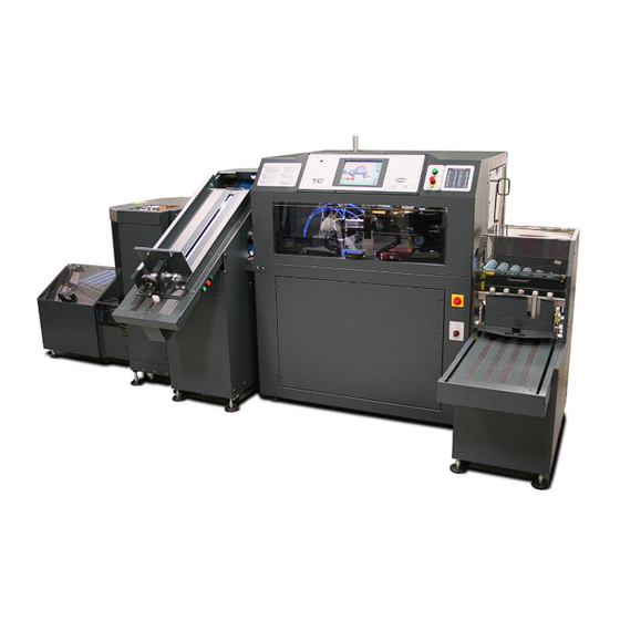
CMT-130TC
Book Trimmer
Service Manual
Serial Numbers: 130TC-A-160000 and up
This manual covers: Hand-Feed Conveyor, Ad-
vanced Infeed Conveyor, Cooling Elevator, and
Exit Conveyor.
For Book Pile Feeder, see manual: F.501( )
For Vertical Stacker, see manual: F.502( )
CAUTION
Certain components in the CMT-130TC are sus-
ceptible to damage due to electrostatic dis-
charge. Observe all ESD procedures to avoid
component damage.
FX.013B
Issued:
February 2016
Last Revised:
5/3/2019
CMT-130 Book Trimmer
THE CHALLENGE MACHINERY COMPANY
SERIAL No.: ____________________
FX.013B / MAY 2019
Advertisement
Table of Contents

Related Manuals for Challenge CMT-130TC


Summary of Contents for Challenge CMT-130TC
- Page 1 Exit Conveyor. For Book Pile Feeder, see manual: F.501( ) For Vertical Stacker, see manual: F.502( ) CAUTION Certain components in the CMT-130TC are sus- ceptible to damage due to electrostatic dis- charge. Observe all ESD procedures to avoid component damage.
-
Page 2: Introduction
The Challenge Machinery Company 6125 Norton Center Drive Products may be unsupported by The Challenge Machinery Company due to age or the unavail- Norton Shores, MI 49441 USA ability of parts from their original manufacturer. No parts or product support will be available to Phone: 231.799.8484 Fax: 231.798.1275... -
Page 3: Safety
Read and understand all instructions thoroughly before using the machine. If questions remain, contact your Author- ized Challenge Dealer. Failure to un- derstand the operating instructions may result in personal injury. Only trained and authorized individuals should operate this machine. -
Page 4: Revision Control List
Revision Control List Page Rev. Page Rev. Page Rev. Page Rev. Page Rev. Page Rev. MAY 2019 Introduction CMT-130TC Book Trimmer... -
Page 5: Table Of Contents
RAP 2.23 Gripper Rotator Lock Cylinder ... 2-31 REP 4.12 Air Filter Change ....... 4-17 RAP 2.67 Stacker Door Interlock ....... 2-75 RAP 2.24 Knife Shift Cylinders ......2-32 ADJ 4.13 Hydraulic System Pressure ....4-18 MAY 2019 CMT-130TC Book Trimmer Introduction... - Page 6 Contents .............. 6-1 Contents .............. 8-1 PL 5.28 Elevator 56421TCA (1/7) ..... 5-29 Introduction ............6-1 Introduction ............8-1 PL 5.29 Elevator 56421TCA (2/7) ..... 5-30 GP 6.1 Retrieve Recent Error Messages .... 6-2 MAY 2019 Introduction CMT-130TC Book Trimmer...
- Page 7 8.3 Moving ............8-2 8.4 Infeed Setup ..........8-3 8.5 Trimmer Height Setup ......... 8-12 8.6 Outfeed Setup ..........8-13 8.7 Main Power Hookup ........8-17 8.8 Main Air Hookup .......... 8-19 8.9 Cleaning ............8-20 MAY 2019 CMT-130TC Book Trimmer Introduction...
-
Page 8: About This Manual
ADJ 4.x or REP 4.x. training with specific procedures and necessary Warning Definition: The "4" refers to section number in this manual. reference information to efficiently service the CMT-130TC Book Trimmer. Section 5 – Parts List WARNING This section contains exploded view drawings Organization... -
Page 9: Power Lockout Procedure
Do not disable safety devices. Crush / Entanglement Hazard! Do not operate with covers or On/Off Switch guards removed. Electrical Shock Hazard! Disconnect power before removing cover. Electrical Shock Hazard! Disconnect power before removing Main Power Disconnect cover. MAY 2019 CMT-130TC Book Trimmer Introduction... - Page 10 NOTES MAY 2019 Introduction CMT-130TC Book Trimmer...
-
Page 11: Service Call Procedures
Monday-Friday, 8:00 am- 5:00 pm EST Bourg, Inc. in the same box the new part was vice. Telephone: 1-508-998-2171 shipped. 3. Xerox CSE responds to customer: Fax: 1-508-998-0933 a. Review system setup 1-508-998-2391 b. Troubleshoot problem MAY 2019 CMT-130TC Book Trimmer 1. Service Call Procedures... - Page 12 Time and Material (T&M) is not supported by Xerox Service Offline units only (not connected to printer) Customer Responsibilities: Customer must stock the CMT-130TC spare parts kit for each site. Customer must ensure adequate inven- tory of spare parts are maintained on- site at all times.
-
Page 13: Status Indicator Raps
RAP 2.79 Exit Conveyor Full Sensor ....2-87 RAP 2.39 Left Jogger Retract Sensor ....2-47 RAP 2.80 Final Actions/System Checks .... 2-88 RAP 2.40 Registration Preset Sensor ....2-48 RAP 2.41 Face Jog Sensor ....... 2-49 MAY 2019 CMT-130TC Book Trimmer 2. Status Indicator RAPs... -
Page 14: Rap 2.1 Fault Entry
6. When possible, attempt to resolve and clear 11. Is the problem a book quality problem? the error message (for example, for an open door message, close the door). It may be MAY 2019 2. Status Indicator RAPs CMT-130TC Book Trimmer... -
Page 15: Rap 2.2 Error Messages
RAP 2.6 Touch Screen Display EE memory Read Fail GP 6.4 Updating Machine Software REP 4.24 Console PWB Replacement EE memory Write failed GP 6.4 Updating Machine Software REP 4.24 Console PWB Replacement MAY 2019 CMT-130TC Book Trimmer 2. Status Indicator RAPs... - Page 16 RAP 2.17 Hydraulic Unload and Flow Valve RAP 2.18 Cut Valve Knife failed to leave up limit in time RAP 2.44 Knife Up Sensor RAP 2.17 Hydraulic Unload and Flow Valve RAP 2.18 Cut Valve MAY 2019 2. Status Indicator RAPs CMT-130TC Book Trimmer...
- Page 17 RAP 2.78 Exit Conveyor Motor No Air Pressure! RAP 2.20 Pneumatic Pressure Output is Full RAP 2.79 Exit Conveyor Full Sensor Pile Feeder Book Not Received See Book Pile Feeder Instruction and Parts Manual MAY 2019 CMT-130TC Book Trimmer 2. Status Indicator RAPs...
- Page 18 RAP 2.76 Stacker Pusher Cylinder Sensor RAP 2.71 Stacker Pusher Cylinder Stop Button is Pressed RAP 2.14 E-Stop/Remote E-Stop Buttons Target Position out of range See Installation and Operator's Manual for allowed dimensions MAY 2019 2. Status Indicator RAPs CMT-130TC Book Trimmer...
-
Page 19: Rap 2.3 Faults Without An Error Message
RAP 2.45 Knife Slow-Down Sensor Paper scrap does not blow into waste bin RAP 2.29 Scrap Air Blast Start button or remote cut button does not work RAP 2.13 Start/Remote Cut Buttons MAY 2019 CMT-130TC Book Trimmer 2. Status Indicator RAPs... - Page 20 RAP 2.77 Stacker Tray Full Sensor Exit Conveyor Accessory Faults Exit Conveyor does not run RAP 2.78 Exit Conveyor Motor Exit Conveyor doesn’t stop when full RAP 2.79 Exit Conveyor Full Sensor MAY 2019 2. Status Indicator RAPs CMT-130TC Book Trimmer...
- Page 21 Partner products get a signal that the trimmer is shut down RAP 2.19 Shutdown Relay when it is actually operating, partner products get a signal that the trimmer is operating when it is shut down MAY 2019 CMT-130TC Book Trimmer 2. Status Indicator RAPs...
-
Page 22: Rap 2.4 Input Power
Disconnect main power and replace trans- former T1 (PL 5.1 Main Assembly 59000 2. Remove the electrical panel door located on (1/14)). the lower right side of the machine. Check MAY 2019 CMT-130TC Book Trimmer 2-10 2. Status Indicator RAPs... - Page 23 Figure 2-3. T1 Transformer Figure 2-2. Input Power and Circuit Breaker Locations MAY 2019 CMT-130TC Book Trimmer 2-11 2. Status Indicator RAPs...
-
Page 24: Rap 2.5 Dc Power
Reset circuit breaker CB8. If circuit breaker ure 2-2)? continues to trip, use applicable schematic to troubleshoot affected circuit (Section 7, Wiring Data). Check and repair wires 48 and Go to RAP 2.4 Input Power MAY 2019 2. Status Indicator RAPs 2-12 CMT-130TC Book Trimmer... - Page 25 Figure 2-4. T2, T3, and BR1 Wire Connections MAY 2019 CMT-130TC Book Trimmer 2-13 2. Status Indicator RAPs...
-
Page 26: Rap 2.6 Touch Screen Display
2. Is there 16 VAC between the two blue wires and also 18 VAC between the two red wires (Figure 2-5)? Replace transformer on console (PL 5.18 Control Console EE-3456-6). MAY 2019 2. Status Indicator RAPs 2-14 CMT-130TC Book Trimmer... -
Page 27: Rap 2.7 Led Enclosure Lights
Repair if necessary. Did this fix the prob- lem? Disconnect main power and replace any LED light board that is not functioning (PL 5.13 Main Assembly 59000 (13/14)). Repair complete. MAY 2019 CMT-130TC Book Trimmer 2-15 2. Status Indicator RAPs... -
Page 28: Rap 2.8 Cooling Fans
Figure 2-7. Fan Locations Check and repair any loose wires 21 and 22. 2. Disconnect main power and replace the faulty fan (PL 5.1 Main Assembly 59000 (1/14)). MAY 2019 2. Status Indicator RAPs 2-16 CMT-130TC Book Trimmer... -
Page 29: Rap 2.9 Status Light
1. Switch the main power ON. Go to the diag- nostic screen and enable outputs (GP 6.2 Input/Output Diagnostics). Activate the sta- tus light red, status light yellow, and status light red outputs. Are output LED’s 1, 9, and MAY 2019 CMT-130TC Book Trimmer 2-17 2. Status Indicator RAPs... -
Page 30: Rap 2.10 Door Interlocks - Trimmer
Disconnect power and replace the Open Figure 2-10. Open Door Indicator PWB Door Indicator PWB (Figure 2-10). 2. Check the operation of the indicated inter- lock switch and make sure that the actuator MAY 2019 2. Status Indicator RAPs 2-18 CMT-130TC Book Trimmer... -
Page 31: Rap 2.11 Interlock Test
RAP 2.11 Interlock Test 6. Locate the normally open contacts and test continuity. Is there continuity on the nor- The interlock switches used in the CMT-130TC mally closed contacts? and accessories are comprised of switch bodies that mount inside the trimmer or accessory, and The switch is defective and should be re- actuator keys that mount to each door. -
Page 32: Rap 2.12 Interlock Relay
Disconnect power and replace the IR relay 10. Cycle power OFF and then back ON. Is in- (PL 5.16 Power Panel EE-3503 (1/2)). put LED 1 off? Figure 2-13. Interlock Relay MAY 2019 2. Status Indicator RAPs 2-20 CMT-130TC Book Trimmer... -
Page 33: Rap 2.13 Start/Remote Cut Buttons
2. Switch the main power ON and go to the di- agnostic screen (GP 6.2 Input/Output Diag- nostics). Are inputs “Rear Start” and “Front Figure 2-15. Remote Cut Button Start” both off? MAY 2019 CMT-130TC Book Trimmer 2-21 2. Status Indicator RAPs... -
Page 34: Rap 2.14 E-Stop/Remote E-Stop Buttons
Stop” both off? Disconnect wires 40 and 41 from the main PWB. Does the diagnostic screen now show inputs "Rear Stop" and "Front Stop" both off? Figure 2-17. Remote E-Stop Button MAY 2019 2. Status Indicator RAPs 2-22 CMT-130TC Book Trimmer... -
Page 35: Rap 2.15 Starter Circuit
2. Go to RAP 2.14 E-Stop/Remote E-Stop But- tons. 3. Go to RAP 2.16 Hydraulic Motor Relay. 4. Go to RAP 2.12 Interlock Relay. 5. Go to RAP 2.10 Door Interlocks. Figure 2-18. HMR and IR Relays MAY 2019 CMT-130TC Book Trimmer 2-23 2. Status Indicator RAPs... -
Page 36: Rap 2.16 Hydraulic Motor Relay
2 Ω? Disconnect power and replace the main Replace the overload relay, OLH (PL 5.16 PWB (REP 4.23 Main PWB Replacement). Power Panel EE-3503 (1/2)). Figure 2-19. Hydraulic Motor Relay MAY 2019 2. Status Indicator RAPs 2-24 CMT-130TC Book Trimmer... -
Page 37: Rap 2.17 Hydraulic Unload And Flow Valves
Check for loose wire 74 at the electrical Disconnect power and replace the propor- panel. tional cartridge valve (PL 5.23 Hydraulic Figure 2-20. Hydraulic Flow and Unload Power Unit – 60Hz 59010). Check circuit breaker CB8. Valves MAY 2019 CMT-130TC Book Trimmer 2-25 2. Status Indicator RAPs... -
Page 38: Rap 2.18 Cut Valve
VDC power supply. Is the power supply okay? Disconnect power and repair the 24 VDC power supply. Disconnect power and replace the main Figure 2-22. Murr Adapter PWB (REP 4.23 Main PWB Replacement). MAY 2019 2. Status Indicator RAPs 2-26 CMT-130TC Book Trimmer... -
Page 39: Rap 2.19 Shutdown Relay
Figure 2-23. Shutdown Relay LED 14 switch on? Disconnect power and replace the main PCB (REP 4.23 Main PWB Replacement). 4. Is there 24 VDC between wires 39 and 73 at the relay? MAY 2019 CMT-130TC Book Trimmer 2-27 2. Status Indicator RAPs... -
Page 40: Rap 2.20 Pneumatic Pressure
(inside the rear door and behind the main pressure gauge). Adjust main regulator to 80-90 psi using the control knob on the main regulator. Figure 2-25. Pressure Switch MAY 2019 2. Status Indicator RAPs 2-28 CMT-130TC Book Trimmer... -
Page 41: Rap 2.21 Left Jogger Cylinder
(GP 6.2 Input/Output Diagnos- the air hose labeled “P” from the pressure tics). Press the Set PWM1 0% button, then control valve and re-route as shown in Fig- ure 2-27. MAY 2019 CMT-130TC Book Trimmer 2-29 2. Status Indicator RAPs... -
Page 42: Rap 2.22 Gripper Clamp Cylinder
Adjust gripper clamp guide screws until grip- per clamp travels up and down freely, but is not allowed to twist. 4. Switch the main air ON. Figure 2-28. Gripper Clamp MAY 2019 2. Status Indicator RAPs 2-30 CMT-130TC Book Trimmer... -
Page 43: Rap 2.23 Gripper Rotator Lock Cylinder
Disconnect power and air, then replace valve #3 (PL 5.22 Pneu. Manifold Asm. 59012-1). 3. Electrically activate valve #3 by shorting wire 59 to wire 74. Does the cylinder retract? MAY 2019 CMT-130TC Book Trimmer 2-31 2. Status Indicator RAPs... -
Page 44: Rap 2.24 Knife Shift Cylinders
(Figure 2-33). Figure 2-32. Knife Shift Cylinders Do the cylinders extend? Disconnect power and air, then replace valve #5 (PL 5.22 Pneu. Manifold Asm. 59012-1). MAY 2019 2. Status Indicator RAPs 2-32 CMT-130TC Book Trimmer... -
Page 45: Rap 2.25 Gripper Lift Cylinder
3. Electrically activate valve #6 by shorting wire 69 to 74 at the main PWB. Does the valve activate? Disconnect power and replace valve #6 (PL 5.22 Pneu. Manifold Asm. 59012-1). Figure 2-35. Pneumatic Valve #6 MAY 2019 CMT-130TC Book Trimmer 2-33 2. Status Indicator RAPs... -
Page 46: Rap 2.26 Registration Plate Extend Cylinder
2. Manually activate valve #7A by pressing the actuator button on the valve (Figure 2-37). Does the plate extend outward approxi- mately 1/2”? Disconnect power and replace valve #7 (PL 5.22 Pneu. Manifold Asm. 59012-1). MAY 2019 2. Status Indicator RAPs 2-34 CMT-130TC Book Trimmer... -
Page 47: Rap 2.27 Book Lift Air Blast
Disconnect power and replace valve #7 (PL 5.22 Pneu. Manifold Asm. 59012-1). 3. Electrically activate valve #7B by shorting wire 33 to 74 on the main PWB. Does the valve activate? MAY 2019 CMT-130TC Book Trimmer 2-35 2. Status Indicator RAPs... -
Page 48: Rap 2.28 Knife Latch Cylinder
3. Open the rear door and move the knife latch cylinder in and out by hand. Does the cylin- der move freely? Figure 2-41. Pneumatic Valve #8 MAY 2019 2. Status Indicator RAPs 2-36 CMT-130TC Book Trimmer... -
Page 49: Rap 2.29 Scrap Air Blast
72 to 74 on the main PWB. Does air blast off the knife bar? Disconnect power and replace valve #9 (PL 5.22 Pneu. Manifold Asm. 59012-1). 4. Disconnect power and replace the main PWB (REP 4.23 Main PWB Replacement). MAY 2019 CMT-130TC Book Trimmer 2-37 2. Status Indicator RAPs... -
Page 50: Rap 2.30 Book Gate Cylinder
Disconnect power and replace valve #10 Figure 2-44. Book Gate (PL 5.22 Pneu. Manifold Asm. 59012-1). 4. Electrically activate valve #10 by shorting wire 100 to 74 at the main PWB. Does the valve activate? MAY 2019 2. Status Indicator RAPs 2-38 CMT-130TC Book Trimmer... -
Page 51: Rap 2.31 Face Jog Cylinder
2. Manually activate valve #11 by pressing the actuator button on the valve (Figure 2-47). Does the face jog cylinder rotate into posi- tion? Disconnect power and replace valve #11 (PL 5.22 Pneu. Manifold Asm. 59012-1). MAY 2019 CMT-130TC Book Trimmer 2-39 2. Status Indicator RAPs... -
Page 52: Rap 2.32 Left And Right Clamp Cylinders
Check for loose or damaged wires 70 and 94 at the electrical panel. Check that the cable connectors on valve #13 are connected properly. Procedure 1. Switch the main air ON and main power ON. MAY 2019 2. Status Indicator RAPs 2-40 CMT-130TC Book Trimmer... -
Page 53: Rap 2.33 Internal Conveyor Motor
(PL 5.11 Main Assembly 59000 (11/14)). 4. Remove the short, then go to the diagnostic screen (GP 6.2 Input/Output Diagnostics) and enable outputs. Make sure all doors are Figure 2-50. Internal Conveyor Motor MAY 2019 CMT-130TC Book Trimmer 2-41 2. Status Indicator RAPs... -
Page 54: Rap 2.34 Registration Assembly Motor
4. Check voltage between wires 14 and 16 at Disconnect power and replace the main EMI #1 on the electrical panel (Figure 2-54). PWB (REP 4.23 Main PWB Replacement). Is there 120 VAC? Figure 2-54. EMI #1 MAY 2019 2. Status Indicator RAPs 2-42 CMT-130TC Book Trimmer... -
Page 55: Rap 2.35 Gripper Transport Servo Motor
(PL 5.9 Main Assembly 59000 (9/14)). 2. Go to the diagnostic screen and enable out- puts (GP 6.2 Input/Output Diagnostics). Repair complete. Figure 2-56. Electrical Panel Connections MAY 2019 CMT-130TC Book Trimmer 2-43 2. Status Indicator RAPs... -
Page 56: Rap 2.36 Gripper Rotation Servo Motor
Open the rear door and re- motor (PL 5.7 Main Assembly 59000 (7/14)). move the waste chute. Close the rear door and all other doors. Repair complete. Figure 2-58. Electrical Panel Connections MAY 2019 2. Status Indicator RAPs 2-44 CMT-130TC Book Trimmer... -
Page 57: Rap 2.37 Knife Latch Sensor
Adjust the sensor (GP 6.5 Proximity Sen- Figure 2-59. Knife Latch Sensor sors) and replace if faulty (PL 5.5 Main As- sembly 59000 (5/14)). 3. Short wire 13 to wire 74. Does the input switch on? MAY 2019 CMT-130TC Book Trimmer 2-45 2. Status Indicator RAPs... -
Page 58: Rap 2.38 Book In Gripper Sensor
Does the diagnostic screen show input “Book in Grip” on? Short wire 35 to 74 at the main PWB. On the diagnostic screen does input "Book in Grip" switch on? MAY 2019 2. Status Indicator RAPs 2-46 CMT-130TC Book Trimmer... -
Page 59: Rap 2.39 Left Jogger Retract Sensor
"Left In" switch on? Disconnect power and replace the con- sole PWB (REP 4.24 Console PWB Re- placement). Replace sensor (PL 5.17 Power Panel EE- 3503 (2/2)). MAY 2019 CMT-130TC Book Trimmer 2-47 2. Status Indicator RAPs... -
Page 60: Rap 2.40 Registration Preset Sensor
4. Close the door and switch the main power ON. Go to the diagnostic screen (GP 6.2 In- put/Output Diagnostics). Does the diagnostic screen show input “Registration Preset” on? MAY 2019 2. Status Indicator RAPs 2-48 CMT-130TC Book Trimmer... -
Page 61: Rap 2.41 Face Jog Sensor
Figure 2-65. Face Jog Cylinder On the diagnostic screen does input "Face Jog Rotary Down" switch on? Disconnect power and replace the main PWB (REP 4.23 Main PWB Replace- ment). MAY 2019 CMT-130TC Book Trimmer 2-49 2. Status Indicator RAPs... -
Page 62: Rap 2.42 Gripper Rotation Preset Sensor
PWB (REP 4.23 Main PWB Replace- Figure 2-66. Rotator Preset Sensor ment). Adjust the sensor (GP 6.5 Proximity Sen- sors) and replace if faulty (PL 5.7 Main As- sembly 59000 (7/14)). MAY 2019 2. Status Indicator RAPs 2-50 CMT-130TC Book Trimmer... -
Page 63: Rap 2.43 Knife Position Sensor
Go to RAP 2.24 Knife Shift Cylinders. 3. Switch the main power OFF and then ON. Go to the diagnostic screen (GP 6.2 In- put/Output Diagnostics). Does the diagnostic screen show input “Knife Center Position” off? MAY 2019 CMT-130TC Book Trimmer 2-51 2. Status Indicator RAPs... -
Page 64: Rap 2.44 Knife Up Sensor
Disconnect power and replace the main PWB (REP 4.23 Main PWB Replace- ment). Adjust the sensor (GP 6.5 Proximity Sen- sors) and replace if faulty (PL 5.4 Main As- sembly 59000 (4/14)). MAY 2019 2. Status Indicator RAPs 2-52 CMT-130TC Book Trimmer... -
Page 65: Rap 2.45 Knife Slow-Down Sensor
Adjust the sensor (GP 6.5 Proximity Sen- sors) and replace if faulty (PL 5.4 Main As- sembly 59000 (4/14)). 2. Short wire 36 to 74. On the diagnostic screen does input "Knife Slowdown" switch MAY 2019 CMT-130TC Book Trimmer 2-53 2. Status Indicator RAPs... -
Page 66: Rap 2.46 Knife Down Switches
Check and repair loose or damaged wire 46 at machine ground. On the diagnostic screen the electrical panel. does input "Knife Down" switch on? The following procedure must be performed with the knife up. Figure 2-71. DI/HS PWB MAY 2019 2. Status Indicator RAPs 2-54 CMT-130TC Book Trimmer... -
Page 67: Rap 2.47 Book Entering Cmt Sensor
1. Make sure that both the sensor and the re- flector are not obstructed. Switch the main power ON and go to the diagnostic screen (GP 6.2 Input/Output Diagnostics). Does the MAY 2019 CMT-130TC Book Trimmer 2-55 2. Status Indicator RAPs... -
Page 68: Rap 2.48 Book Width Sensor
“Book Width” switched on? Short wire 82 to 74 at the main PWB. On Figure 2-73. Book Width Sensor the diagnostic screen does input "Book Width" switch on? MAY 2019 2. Status Indicator RAPs 2-56 CMT-130TC Book Trimmer... -
Page 69: Rap 2.49 Book Thickness Sensor
Is there 15VDC between wires 12 and 98 at Repair complete. the DI/HS PWB (Figure 2-75)? Is there 24VDC between wires 73 and Figure 2-75. DI/HS PWB 74 at the DI/HS PWB? MAY 2019 CMT-130TC Book Trimmer 2-57 2. Status Indicator RAPs... -
Page 70: Rap 2.50 Barcode Scanner
For more information about the barcode capabil- Replace barcode scanner (PL 5.13 Main As- ities and settings, see the CMT-130TC’s Installa- tion and Operator’s Manual. sembly 59000 (13/14) or PL 5.14 Main As- sembly 59000 (14/14)). -
Page 71: Rap 2.51 Elevator Input Power
The Elevator and Tilt Conveyor receive power Is there 120VAC at wire 23 at circuit breaker and communications from the CMT-130TC by CB1 and wire 22? way of a power cable and communications cable that come from the trimmer. -
Page 72: Rap 2.52 Elevator Door Interlocks
MAY 2019 2. Status Indicator RAPs 2-60 CMT-130TC Book Trimmer... -
Page 73: Rap 2.53 Elevator Tilt Table Cylinders
Check for loose or damaged wire 56 at the Ele- vator’s electrical panel. Check that the cable connector on the air valve is connected properly. Procedure 1. Switch the main air ON and main power ON. MAY 2019 CMT-130TC Book Trimmer 2-61 2. Status Indicator RAPs... -
Page 74: Rap 2.54 Elevator Tilt Infeed Motors
(PL 5.43 Tilt Conveyor 56600TCA (5/8), 4. Inside the conveyor case, locate the 3 SSR’s. Check AC voltage between wire 11 PL 5.44 Tilt Conveyor 56600TCA (6/8), or PL 5.71 Conveyor Drive Asm. 56340-1). MAY 2019 2. Status Indicator RAPs 2-62 CMT-130TC Book Trimmer... -
Page 75: Rap 2.55 Elevator Lift Motor
Elevator is getting proper power. 2. Switch the main power ON and press the green start button to initialize the trimmer. Remove the Elevator lift motor cover. Feed MAY 2019 CMT-130TC Book Trimmer 2-63 2. Status Indicator RAPs... -
Page 76: Rap 2.56 Elevator Pusher Cylinder
2. Pull the Elevator away from the machine to access the flow control on the right side of the Elevator. Fully open the flow control valve on the right side. Figure 2-83. Elevator Pusher MAY 2019 2. Status Indicator RAPs 2-64 CMT-130TC Book Trimmer... -
Page 77: Rap 2.57 Book In From Binder Sensor
Disconnect wire 42 from the Elevator I/O PWB (Figure 2-86). Does the input switch off? Disconnect power and replace the Ele- vator I/O PWB (REP 4.26 Accessory Figure 2-85. Book In From Binder Sensor PWB Replacement). MAY 2019 CMT-130TC Book Trimmer 2-65 2. Status Indicator RAPs... -
Page 78: Rap 2.58 Tilt Up Switch
Short wire 41 to 74. On the diagnostic screen does input “Tilt Up” switch on? Disconnect power and replace the Ele- vator I/O PWB (REP 4.26 Accessory Figure 2-87. Tilt Up Switch PWB Replacement). MAY 2019 2. Status Indicator RAPs 2-66 CMT-130TC Book Trimmer... -
Page 79: Rap 2.59 Book On Tilt Sensors
Tilt 1” and “Book on Tilt 2” both off? Disconnect wires 44 and 45. On the diag- nostic screen do both “Book on Tilt” inputs Figure 2-89. Book on Tilt Sensors switch off? MAY 2019 CMT-130TC Book Trimmer 2-67 2. Status Indicator RAPs... -
Page 80: Rap 2.60 Book Entering Elevator Sensor
Is input “Book In Elevator” off? Disconnect wire 59. On the diagnostic screen does input “Book In Elevator” switch off? Figure 2-91. Book Entering Elevator Sensor Figure 2-93. Elevator Electrical Panel MAY 2019 2. Status Indicator RAPs 2-68 CMT-130TC Book Trimmer... -
Page 81: Rap 2.61 Elevator Book At Top Sensor
Is input “Book On Top” off? Disconnect wire 48. On the diagnostic Figure 2-94. Elevator Book at Top Sensor screen does input “Book On Top” switch off? MAY 2019 CMT-130TC Book Trimmer 2-69 2. Status Indicator RAPs... -
Page 82: Rap 2.62 Shelf Level Detect Sensor
56421TCA (3/7) or PL 5.37 Elev. Electrical Panel EE-3523). Disconnect wire 40. On the diagnostic screen does input “Shelf Level Detect” Repair Complete. switch off? Figure 2-97. Elevator Electrical Panel MAY 2019 2. Status Indicator RAPs 2-70 CMT-130TC Book Trimmer... -
Page 83: Rap 2.63 Elevator Empty Sensor
Disconnect wire 47. On the diagnostic screen does input “Elevator Empty” switch off? Disconnect power and replace the Ele- Figure 2-98. Elevator Empty Sensor vator I/O PWB (REP 4.26 Accessory PWB Replacement). MAY 2019 CMT-130TC Book Trimmer 2-71 2. Status Indicator RAPs... -
Page 84: Rap 2.64 Elevator Pusher Home Sensor
2. Go to the Elevator diagnostic screen (GP Repair complete. 6.2 Input/Output Diagnostics). Is input “Pusher Home” on? Short wire 46 to 74. On the diagnostic screen does input “Pusher Home” switch Figure 2-101. Elevator Electrical Panel MAY 2019 2. Status Indicator RAPs 2-72 CMT-130TC Book Trimmer... -
Page 85: Rap 2.65 Elevator Pusher Interlock
Go to RAP 2.55 Elevator Lift Motor. 3. With the hydraulic motor still running, is there 120 VAC between wire 25 at SSR1 and wire 22 at the electrical panel? MAY 2019 CMT-130TC Book Trimmer 2-73 2. Status Indicator RAPs... -
Page 86: Rap 2.66 Stacker Input Power
The Vertical Stacker receives power and com- schematic to troubleshoot affected circuit munications from the CMT-130TC by way of a (Section 7, Wiring Data). power cable and communications cable that 3. Switch off main power and check fuse F1 on come from the trimmer. -
Page 87: Rap 2.67 Stacker Door Interlock
Diagnostics). Open the door. Is a tone heard with each opening and clos- ing? Disconnect power and replace the defective interlock switch (PL 5.62 Outfeed Stacker 58000TCA (8/9)). Repair complete. MAY 2019 CMT-130TC Book Trimmer 2-75 2. Status Indicator RAPs... -
Page 88: Rap 2.68 Stacker Roller Motor
Stacker electrical panel. 3. With the hydraulic motor is still running, go to the Stacker diagnostic screen (GP 6.2 In- put/Output Diagnostics) and enable outputs. Activate the “Roller Motor” output. MAY 2019 2. Status Indicator RAPs 2-76 CMT-130TC Book Trimmer... -
Page 89: Rap 2.69 Stacker Tray Up/Down Cylinder
Fully open Figure 2-107. Tray Up/Down Cylinder, Valve the flow control valves located at the air fit- tings on the cylinder. 2. Switch the main air ON and main power ON. MAY 2019 CMT-130TC Book Trimmer 2-77 2. Status Indicator RAPs... -
Page 90: Rap 2.70 Stacker Tray Dump Cylinder
Figure 2-108. Tray Dump Cylinder, Valve 2. Switch the main air ON and main power ON. 3. Manually activate the tray dump valve by pressing the actuator button on the valve MAY 2019 2. Status Indicator RAPs 2-78 CMT-130TC Book Trimmer... -
Page 91: Rap 2.71 Stacker Pusher Cylinder
Stacker, and locate the pusher cylin- pusher cylinder moves at a moderate speed der. Fully open the flow control valves lo- (GP 6.14 Speed-Control Air Valves). cated at the air fittings on the cylinder. MAY 2019 CMT-130TC Book Trimmer 2-79 2. Status Indicator RAPs... -
Page 92: Rap 2.72 Stacker Finger Lift Cylinder
2. Switch the main air ON and main power ON. The fingered gate should raise up by default. 3. Manually activate the finger valve by press- ing the actuator button on the valve (Figure Figure 2-110. Finger Lift Cylinder MAY 2019 2. Status Indicator RAPs 2-80 CMT-130TC Book Trimmer... -
Page 93: Rap 2.73 Stacker Roller Start Sensor
Stacker diagnostic screen (GP 6.2 In- put/Output Diagnostics). Make sure that the sensor is not obstructed. Is input “Roller Start” off? Disconnect wire 67. On the diagnostic screen does input “Roller Start” switch off? MAY 2019 CMT-130TC Book Trimmer 2-81 2. Status Indicator RAPs... -
Page 94: Rap 2.74 Stacker Book In Tray Sensor
Stacker diagnostic screen (GP 6.2 In- put/Output Diagnostics). Make sure that the sensor is not obstructed. Is input “Book In” off? Disconnect wire 65. On the diagnostic screen does input “Book In” switch off? MAY 2019 2. Status Indicator RAPs 2-82 CMT-130TC Book Trimmer... -
Page 95: Rap 2.75 Stacker Book To Pusher Sensor
Diagnostics). Make sure that the sensor is not obstructed. Is input “Book To Pusher” off? Disconnect wire 66. On the diagnostic screen does input “Book To Pusher” switch Figure 2-115. Stacker Electrical Panel off? MAY 2019 CMT-130TC Book Trimmer 2-83 2. Status Indicator RAPs... -
Page 96: Rap 2.76 Stacker Pusher Cylinder Sensor
2. Go to the Stacker diagnostic screen (GP 6.2 Input/Output Diagnostics). Is input “Cyl. Prox” on? Short wire 69 to 74. On the diagnostic screen does input “Cyl. Prox” switch on? MAY 2019 2. Status Indicator RAPs 2-84 CMT-130TC Book Trimmer... -
Page 97: Rap 2.77 Stacker Tray Full Sensor
Stacker diagnostic screen (GP 6.2 In- put/Output Diagnostics). Is input “Tray Full Prox” off? Disconnect wire 68. On the diagnostic screen does input “Tray Full Prox” switch off? Figure 2-117. Stacker Tray Full Sensor MAY 2019 CMT-130TC Book Trimmer 2-85 2. Status Indicator RAPs... -
Page 98: Rap 2.78 Exit Conveyor Motor
Does the trimmer’s hydraulic motor come Go to RAP 2.15 Starter Circuit 4. Inside the conveyor case, is there 120 VAC between wire 25 at SSR1 and wire 22 at the lower terminal block? MAY 2019 2. Status Indicator RAPs 2-86 CMT-130TC Book Trimmer... -
Page 99: Rap 2.79 Exit Conveyor Full Sensor
Go to GP 6.7 Diffuse Sensors (PL 5.67 Exit Conv. 56420TCA (1/3) or PL 5.70 Exit Conv. Elec. Panel EE-3566). 2. Short wire 47 to wire 74. Does the input switch on? MAY 2019 CMT-130TC Book Trimmer 2-87 2. Status Indicator RAPs... -
Page 100: Rap 2.80 Final Actions/System Checks
4. Run at least ten books through the machine. Do the books feed through the machine cor- rectly? Go to CMT-130TC Installation and Operator Manual for proper setup of the trimmer's ac- cessories. 5. Are the books of acceptable quality? Go to BQ 3.1 Book Quality Entry Rap. -
Page 101: Book Quality
They are not intended to correct printing or binding quality issues. Each RAP contains a diagram illustrating the book quality issue. Refer to these diagrams if the de- scription is not understood. MAY 2019 CMT-130TC Book Trimmer 3. Book Quality... -
Page 102: Bq 3.1 Book Quality Entry Rap
Books are not cut square BQ 3.9 Books Not Square ADJ 4.6 Squaring Adjustment RAP 2.23 Gripper Rotator Lock Cylinder RAP 2.21 Left Jogger Cylinder Books are not trimmed accurately BQ 3.10 Books Not Accurately Trimmed MAY 2019 3. Book Quality CMT-130TC Book Trimmer... -
Page 103: Bq 3.2 Burr Marks
Rotate or replace the cut stick (REP 4.1 Replace the knife (REP 4.2 Knife Re- Solutions Cut Stick Replacement). placement). Replace the knife (REP 4.2 Knife Re- Replace the knife (REP 4.2 Knife Re- placement). placement). MAY 2019 CMT-130TC Book Trimmer 3. Book Quality... -
Page 104: Bq 3.5 Rectangular Crease Lines
Note: Reducing the clamp pressure too much Replace the knife (REP 4.2 Knife Re- will cause other quality problems such as draw. placement). Only reduce clamp pressure by necessary amounts. MAY 2019 3. Book Quality CMT-130TC Book Trimmer... -
Page 105: Bq 3.8 All Sheets Not Cut
If normal wear has forced the cutting or transport mechanisms out of square, re- fer the problem to an authorized service agent. See ADJ 4.6 Squaring Adjust- ment. MAY 2019 CMT-130TC Book Trimmer 3. Book Quality... -
Page 106: Bq 3.10 Books Not Accurately Trimmed
Face Jog Cylinder and ADJ 4.22 Face Jog Pressure). Check function of the registration plate extend cylinder (RAP 2.26 Registration Plate Extend Cylinder). Check function of the gripper clamp (ADJ 4.21 Gripper Clamp Pressure). MAY 2019 3. Book Quality CMT-130TC Book Trimmer... -
Page 107: Repair/Adjustment Procedures
ADJ 4.27 Elevator Pusher Height ...... 4-32 ADJ 4.28 Elevator Shelf Synchronization ..4-33 Introduction The Repair/Adjustment Procedures section de- tails the repair, replacement, and adjustment of many parts within the CMT-130TC and its ac- cessory options. MAY 2019 CMT-130TC Book Trimmer 4. Repair/Adjustment Procedures... -
Page 108: Rep 4.1 Cut Stick Replacement
Puller in-line with the cut stick. 5. Pull the Cut Stick Puller at a slight angle (Figure 4-2) over the cut stick until the end of the cut stick comes out of the table. MAY 2019 4. Repair/Adjustment Procedures CMT-130TC Book Trimmer... -
Page 109: Rep 4.2 Knife Replacement
Warn people nearby that a knife is being removed. 7. Slowly turn the knife lifter handles counter- clockwise only until the knife is released Figure 4-5. Knife Bolt Locations MAY 2019 CMT-130TC Book Trimmer 4. Repair/Adjustment Procedures... - Page 110 Have the scabbard nearby and insert knife immediately. Warn Figure 4-7. Knife Adjustment Knob people of any unprotected knife. 3. Move the waste bin aside and open the rear door. MAY 2019 4. Repair/Adjustment Procedures CMT-130TC Book Trimmer...
- Page 111 17. Place 2 knife bolts into the holes from which Bevel Angle the knife lifter handles were removed. Use Knives for the CMT-130TC are shipped from the T-handle wrench to secure them. Challenge with a 20° bevel angle. Challenge Once the knife has been installed, the cutting recommends that a 20°...
-
Page 112: Adj 4.3 Knife Depth Adjustment
This will set the knife depth to the highest position. Figure 4-10. Knife Adj. Knob & Remote Cut 6. Move the waste bin aside and open the rear Button door. MAY 2019 4. Repair/Adjustment Procedures CMT-130TC Book Trimmer... -
Page 113: Adj 4.4 Lubrication
3-in-1® SAE 20 electric motor oil . 4. Squeeze four pumps of a #2 EP molyb- denum grease (such as Challenge part num- ber: SU-30-103) into each of the two bearing housings underneath the table (Figure 4-11). -
Page 114: Adj 4.5 Accuracy Adjustment
3. Press the “Accuracy Adjust” tab to open the Accuracy Adjust screen (Figure 4-15). 4. Follow the instructions on the screen to re- calibrate the trimmer’s accuracy. Figure 4-15. Accuracy Adjust Screen MAY 2019 4. Repair/Adjustment Procedures CMT-130TC Book Trimmer... -
Page 115: Adj 4.6 Squaring Adjustment
9. Tighten the locking set screw and jam nut. 10. Switch the main air ON and the main power MAY 2019 CMT-130TC Book Trimmer 4. Repair/Adjustment Procedures... -
Page 116: Adj 4.7 Knife Down Switches Adjustment
ON. Press the green start button to the leadscrews? initialize the trimmer, then press the “Setup” button to enter the setup screen. MAY 2019 4. Repair/Adjustment Procedures 4-10 CMT-130TC Book Trimmer... - Page 117 Then tighten the clamping screw. Run some more books through the trimmer, and repeat this adjustment if neces- sary. Adjustment Complete. Figure 4-19. DI/HS PWB Figure 4-18. Knife Down Switches MAY 2019 CMT-130TC Book Trimmer 4-11 4. Repair/Adjustment Procedures...
-
Page 118: Adj 4.8 Timing And Conveyor Belt Check/Repl
Procedure Complete. screws. 4. Inspect the two internal conveyor belts (Fig- c. Remove the conveyor belt pulley cover ure 4-21). Are they free of holes, tears, and if installed. excessive edge fraying? MAY 2019 4. Repair/Adjustment Procedures 4-12 CMT-130TC Book Trimmer... - Page 119 Figure 4-20. Registration Timing Belt Figure 4-24. Conveyor Belt Adjustment Figure 4-22. Accessory Conveyor Example Figure 4-23. Exit Conveyor Belts Figure 4-21. Conveyor and Timing Belts MAY 2019 CMT-130TC Book Trimmer 4-13 4. Repair/Adjustment Procedures...
-
Page 120: Adj 4.9 Conveyor Belt Tracking Adjustment
Exit Conveyor: The belt cannot be ing properly. All CMT-130TC conveyor belts are stopped by applying approximately 40 adjusted by the same method. pounds of pressure to the top surface of the belt. -
Page 121: Rep 4.10 Slide Tape
Remove any peeling tape. 3. Clean jogger plates with isopropyl alcohol or acetone. 4. Install new tape and trim around edges and inserts as necessary. Figure 4-26. Slide Tape Locations MAY 2019 CMT-130TC Book Trimmer 4-15 4. Repair/Adjustment Procedures... -
Page 122: Rep 4.11 Oil / Filter Change
5 gallon containers from your authorized Challenge 1. Switch the main power OFF and lockout Dealer using the Challenge part number: S- power to the machine. 1991-3 2. Disconnect and set aside any infeed acces- 9. -
Page 123: Rep 4.12 Air Filter Change
10. Reinstall the filter cylinder. Align the double lines on the cylinder with the double lines on the head. Push the cylinder into the head and twist until the cylinder snaps into place. MAY 2019 CMT-130TC Book Trimmer 4-17 4. Repair/Adjustment Procedures... -
Page 124: Adj 4.13 Hydraulic System Pressure
PSI. If it is not, adjust the relief valve by loosening the valve’s lock nut then turning Figure 4-28. System Pressure Setting the valve screw clockwise to increase pres- sure or counter-clockwise to decrease the pressure. MAY 2019 4. Repair/Adjustment Procedures 4-18 CMT-130TC Book Trimmer... -
Page 125: Adj 4.14 Counterbalance Valve
5. To adjust the counterbalance valve, loosen the lock nut then turn the adjustment screw counter-clockwise to increase pressure or clockwise to decrease pressure. Adjust the screw until the valve operates consistently at 900 PSI. MAY 2019 CMT-130TC Book Trimmer 4-19 4. Repair/Adjustment Procedures... -
Page 126: Adj 4.15 Knife Cushion Adjustment
(02-28-2019 version software and later) like the one shown in Figure 4-32? Move the knife cushion slide bar until the cushion value is approximately set to 185. Now skip to step 7. MAY 2019 4. Repair/Adjustment Procedures 4-20 CMT-130TC Book Trimmer... -
Page 127: Adj 4.16 Book Underside Air Lift
7. When finished adjusting, push the locking ring back in to lock it in place 8. Switch the main power OFF to exit the diag- nostic screen. MAY 2019 CMT-130TC Book Trimmer 4-21 4. Repair/Adjustment Procedures... -
Page 128: Adj 4.17 Knife Gib Adjustment
Figure 4-34. Gib Screws nuts are tightened. 8. Close the door and replace the waste bin. 9. After adjusting gibs, it may be necessary to perform ADJ 4.5 Accuracy Adjustment. MAY 2019 4. Repair/Adjustment Procedures 4-22 CMT-130TC Book Trimmer... -
Page 129: Adj 4.18 Knife Latch
7. Tighten the proximity mounting screws, making sure not to move the sensor while tightening. 8. Close the rear door and replace the waste bin. Figure 4-35. Knife Latch MAY 2019 CMT-130TC Book Trimmer 4-23 4. Repair/Adjustment Procedures... -
Page 130: Adj 4.19 Clamp Pressure Adjustment
4. Once the clamp pressure is set as desired, press down on the locking ring to lock the adjustment knob. 5. Close the rear door. MAY 2019 4. Repair/Adjustment Procedures 4-24 CMT-130TC Book Trimmer... -
Page 131: Adj 4.20 Left Jog Pressure Adjustment
Figure 4-38. Min and Max Left Jog Pressures Failure to do so may result in damage to the jog- ger cylinder! MAY 2019 CMT-130TC Book Trimmer 4-25 4. Repair/Adjustment Procedures... -
Page 132: Adj 4.21 Gripper Clamp Pressure
4. Check the pressure again to make sure it did not change. 5. Once the pressure is set as desired, tighten the adjustment screw lock nut. 6. Reinstall the electrical panel door. MAY 2019 4. Repair/Adjustment Procedures 4-26 CMT-130TC Book Trimmer... -
Page 133: Adj 4.22 Face Jog Pressure
Check the pressure again to make sure it did not change. 4. Once the pressure is set as desired, tighten the adjustment screw lock nut. 5. Reinstall the electrical panel door. MAY 2019 CMT-130TC Book Trimmer 4-27 4. Repair/Adjustment Procedures... -
Page 134: Rep 4.23 Main Pwb Replacement
(Figure 4-41). 6. Carefully remove the new PWB from the electro-static bag that it was shipped in, and place the old PWB in the empty bag. MAY 2019 4. Repair/Adjustment Procedures 4-28 CMT-130TC Book Trimmer... -
Page 135: Rep 4.24 Console Pwb Replacement
USB 5. Click on “Save USB Params” and follow flash drive with the backup file on it into the prompts on the screen. front console. MAY 2019 CMT-130TC Book Trimmer 4-29 4. Repair/Adjustment Procedures... -
Page 136: Rep 4.25 Di/Hs Pwb Replacement
7. Securely connect all cables to the new PWB. 8. Reinstall the electrical panel door/cover. 9. Restore power to the trimmer and switch the main power ON. MAY 2019 4. Repair/Adjustment Procedures 4-30 CMT-130TC Book Trimmer... -
Page 137: Rep 4.26 Accessory Pwb Replacement
6. Install the new PWB on the five standoffs on the electrical panel, and attach it securely with all five nuts. 7. Securely connect all cables to the new PWB. 8. Reinstall the electrical panel door/cover. MAY 2019 CMT-130TC Book Trimmer 4-31 4. Repair/Adjustment Procedures... -
Page 138: Adj 4.27 Elevator Pusher Height
9. Return the pusher to its home position. 10. Close the top cover. 11. Restore power to the trimmer then switch the main power ON and main air ON. MAY 2019 4. Repair/Adjustment Procedures 4-32 CMT-130TC Book Trimmer... -
Page 139: Adj 4.28 Elevator Shelf Synchronization
(Figure 4-48). 7. With the plates level, rotate the adjustment hub counterclockwise by hand to put tension Figure 4-47. Loosen Adjustment Hub on the chain (Figure 4-49). MAY 2019 CMT-130TC Book Trimmer 4-33 4. Repair/Adjustment Procedures... - Page 140 NOTES MAY 2019 4. Repair/Adjustment Procedures 4-34 CMT-130TC Book Trimmer...
-
Page 141: Parts List
PL 5.31 Elevator 56421TCA (4/7) ..... 5-32 The parts list section provides a complete list of PL 5.32 Elevator 56421TCA (5/7) ..... 5-33 parts used in the CMT-130TC. Refer to the PL 5.33 Elevator 56421TCA (6/7) ..... 5-34 PL 5.34 Elevator 56421TCA (7/7) ..... 5-35 parts lists when order repair parts. -
Page 142: 5.1 Main Assembly 59000 (1/14)
WASHER - #6 INT TOOTH H-7327-10 WASHER - 5/16 MEDIUM LOCK H-7327-12 WASHER - 3/8 MEDIUM LOCK H-7327-8 WASHER - 1/4 MEDIUM LOCK S-1121 REDUCING WASHER S-1781-192 LABEL - IDENTIFICATION S-1781-222 LABEL - START/STOP, REAR MAY 2019 5. Parts List CMT-130TC Book Trimmer... -
Page 143: 5.2 Main Assembly 59000 (2/14)
LABEL - AIR MAIN DISC. S-1781-130 LABEL - BOTTOM BLAST S-1781-192 LABEL - IDENTIFICATION S-1781-195 LABEL - MAIN AIR PRESSURE S-1781-196 LABEL - CLAMP PRESSURE S-1781-204 LABEL - COMPRESSED AIR INLET 1 MAY 2019 CMT-130TC Book Trimmer 5. Parts List... -
Page 144: 5.3 Main Assembly 59000 (3/14)
WASHER - 1" HIGH COL. LOCK H-7329-4 WASHER - 1/4 HIGH COL. LOCK P-503-401PT ELBOW-1/4 TUBE X 1/8 PT P-503-402 ELBOW-1/4 TUBE X 1/4 NPT P-506 SILENCER (METRIC THD) P-511 SILENCER - 1/4 NPT MAY 2019 5. Parts List CMT-130TC Book Trimmer... -
Page 145: 5.4 Main Assembly 59000 (4/14)
WASHER - 1/4 MEDIUM LOCK H-7327-#10 WASHER - #10 MEDIUM LOCK H-7329-16 WASHER - 1" HIGH COLLAR LOCK S-1781-61 LABEL - KNDN S-1781-62 LABEL - KNUP S-1818-4 THREADED COLLAR S-1818-8 THREADED COLLAR MAY 2019 CMT-130TC Book Trimmer 5. Parts List... -
Page 146: 5.5 Main Assembly 59000 (5/14)
WASHER - #4 INT TOOTH H-7327-12 WASHER - 3/8 MEDIUM LOCK H-7327-8 WASHER - 1/4 MEDIUM LOCK H-7327-#10 WASHER - #10 MEDIUM LOCK P-503-401 ELBOW-1/4 TUBE X 1/8 NPT S-1725-4 GREASE FITTING - 1/8 NPT MAY 2019 5. Parts List CMT-130TC Book Trimmer... -
Page 147: 5.6 Main Assembly 59000 (6/14)
WASHER - 1/4 MEDIUM LOCK P-503-401 ELBOW-1/4 TUBE X 1/8 NPT P-503-41032 ELBOW-1/4 TUBE X #10-32 P-504-41032 RUN TEE - 1/4 TUBE DIA X 10-32 P-509-401 DBLE UNIV. ELB. 1/4 T X 1/8 NPT MAY 2019 CMT-130TC Book Trimmer 5. Parts List... -
Page 148: 5.7 Main Assembly 59000 (7/14)
P-500-402 STRAIGHT FITTING-1/4 TUBE X 1/4 NPT P-503-401 ELBOW-1/4 TUBE X 1/8 NPT P-503-41032 ELBOW-1/4 TUBE X #10-32 S-1295-5 THRUST WASHER S-1300 THRUST BEARING S-1681-6 WASHER - WAVE SPRING S-1818-7 THREADED COLLAR MAY 2019 5. Parts List CMT-130TC Book Trimmer... -
Page 149: 5.8 Main Assembly 59000 (8/14)
SCREW - M5 X 22MM SOC HD H-6964-410 SCREW - 1/4-20 X 5/8 BRASS TIP P-503-41032 ELBOW-1/4 TUBE X #10-32 P-525-402 ROTARY FTNG - 1/4 T X 1/4 NPT P-526-402 BULKHD FTNG - 1/4 T X 1/4 NPT MAY 2019 CMT-130TC Book Trimmer 5. Parts List... -
Page 150: 5.9 Main Assembly 59000 (9/14)
WASHER - 3/8 SAE PLAIN H-7321-#10 WASHER - #10 SAE PLAIN H-7327-10 WASHER - 5/16 MEDIUM LOCK H-7327-8 WASHER - 1/4 MEDIUM LOCK H-7327-#10 WASHER - #10 MEDIUM LOCK H-7327-#8 WASHER - #8 MEDIUM LOCK MAY 2019 5. Parts List 5-10 CMT-130TC Book Trimmer... -
Page 151: 5.10 Main Assembly 59000 (10/14)
WASHER - 5/16 MEDIUM LOCK H-7327-12 WASHER - 3/8 MEDIUM LOCK H-7327-8 WASHER - 1/4 MEDIUM LOCK P-304 FLOW CTRL ELB.-1/4 T X 1/8 NPT 2 P-500-41032 STR. FTG-1/4 TUBE X 10-32 UNF MAY 2019 CMT-130TC Book Trimmer 5-11 5. Parts List... -
Page 152: 5.11 Main Assembly 59000 (11/14)
WASHER - #10 SAE PLAIN H-7321-#4 WASHER - #4 SAE PLAIN H-7324-#10 WASHER - #10 INT TOOTH H-7324-#4 WASHER - #4 INT TOOTH H-7327-8 WASHER - 1/4 MEDIUM LOCK H-7327-#10 WASHER - #10 MEDIUM LOCK MAY 2019 5. Parts List 5-12 CMT-130TC Book Trimmer... -
Page 153: 5.12 Main Assembly 59000 (12/14)
WASHER - #6 INT TOOTH H-7324-#8 WASHER - #8 INT TOOTH H-7327-8 WASHER - 1/4 MEDIUM LOCK S-1781-221 LABEL - KNIFE CHANGE S-1781-39 LABEL - MOVING PARTS HAZARD 1 W-164 WRENCH - 5/16" HEX T-HANDLE MAY 2019 CMT-130TC Book Trimmer 5-13 5. Parts List... -
Page 154: 5.13 Main Assembly 59000 (13/14)
WASHER - #8 SAE PLAIN H-7324-10 WASHER - 5/16 INT TOOTH H-7324-#8 WASHER - #8 INT TOOTH H-7327-8 WASHER - 1/4 MEDIUM LOCK S-1781-116 LABEL - WARNING S-1781-217 LABEL - START/STOP MAY 2019 5. Parts List 5-14 CMT-130TC Book Trimmer... -
Page 155: 5.14 Main Assembly 59000 (14/14)
WASHER - 1/4 SAE PLAIN H-7327-8 WASHER - 1/4 MEDIUM LOCK S-1781-12 LABEL - SHOCK HAZARD S-1781-220 LABEL - KNIFE ADJUST S-1781-223 LABEL - POWER CONNECTION S-1781-50 LABEL - ELECTRIC SHOCK MAY 2019 CMT-130TC Book Trimmer 5-15 5. Parts List... -
Page 156: 5.15 Registration Asm. 56311-3
H-7327-#10 WASHER - #10 MEDIUM LOCK P-304 FLOW CTRL ELB.-1/4 TUBE X 1/8 NPT P-503-41032 ELBOW-1/4 TUBE X #10-32 S-1350-16 STRAIN RELIEF BUSHING S-1694-2 TYRAP - #10 S-1729-5 WELDNUT - #8-32 MAY 2019 5. Parts List 5-16 CMT-130TC Book Trimmer... -
Page 157: 5.16 Power Panel Ee-3503 (1/2)
SCREW, #1/4-20NC X 3/8" BUT HD CAP E-2756-6 FILTER - FERRITE CORE, LARGE E-2756-9 FILTER - FERRITE CORE, SMALL E-3264-4 CIRCUIT BREAKER - 3A, (CB5) E-3264-7 CIRCUIT BREAKER - 6A, (CB7) E-2507-4 FIXED BRIDGE - 4 POLE MAY 2019 CMT-130TC Book Trimmer 5-17 5. Parts List... -
Page 158: 5.17 Power Panel Ee-3503 (2/2)
SOCKET - SOLENOID (FOR JOG PRESSURE) EE-3556 CABLE ASM. - CONTROL CONSOLE POWER EE-3526 WIRE ASM - CUT LIST EE-2855-17 RIBBON CABLE ASM. - 20 COND. EE-2855-18 RIBBON CABLE ASM. - 14 COND. MAY 2019 5. Parts List 5-18 CMT-130TC Book Trimmer... -
Page 159: 5.18 Control Console Ee-3456-6
E-1214-64 CONNECTOR - 1/4" NON-INS. RING E-2743 WIRE - #18 GA. YEL/GREEN 27" EE-2855-17 RIBBON CABLE ASM. - 20 POS., EE-2855-18 RIBBON CABLE ASM. - 14 POS., EE-3557 CABLE ASM. - BARCODE SCANNER MAY 2019 CMT-130TC Book Trimmer 5-19 5. Parts List... -
Page 160: 5.19 Panel Assembly Ee-3471
WASHER - #6 SAE. FLAT H-6423-#6 NUT - #6-32 HEX H-7321-#10 WASHER - #10 SAE. FLAT H-6910-83203 SCREW - #8-32 X 3/8 BUT HD CAP H-7321-#8 WASHER - #8 SAE. FLAT MAY 2019 5. Parts List 5-20 CMT-130TC Book Trimmer... -
Page 161: 5.20 Pneu. Diag. 59000Tca-P (1/2)
3/8" O.D. P.E. TUBING (SOLID BLUE) P-303-4 3/8" O.D. P.U. TUBING (TRANS. BLUE) 56668 COLLET COVER - RED P-516 PUSH-IN CONNECTOR (1/4 SHUT-OFF) 2 TUBING ASSEMBLY – INFEED ACC. REF 59155 MAY 2019 CMT-130TC Book Trimmer 5-21 5. Parts List... -
Page 162: 5.21 Pneu. Diag. 59000Tca-P (2/2)
1/4" O.D. P.U. TUBING (TRANS. BLUE) P-510-4 AIR FLOW REGULATOR - 1/4" TUBE P-508-4 UNION "Y" - 1/4 TUBE DIA. P-318 PLUG P-527-4 QUICK EXHAUST VALVE P-518-4 PUSH-IN CONNECTOR - 1/4 COUPLING 1 MAY 2019 5. Parts List 5-22 CMT-130TC Book Trimmer... -
Page 163: 5.22 Pneu. Manifold Asm. 59012-1
VALVE - 2 POSITION 56011 VALVE - 3 POS., EXH. CENTER 56011-2 VALVE - 3 POS., PRESS. CENTER 1 56012 REGULATOR - MANIFOLD 56013 INDIVIDUAL SUPPLY SPACER 59012-1-M MANIFOLD - 13 STATION MAY 2019 CMT-130TC Book Trimmer 5-23 5. Parts List... -
Page 164: Pl 5.23 Hydraulic Power Unit - 60Hz 59010
SCREW - 5/16-18 X 2 SOC HD H-6918-808 SCREW - 1/2-13 X 1 SOC HD H-7321-5 WASHER - 5/16 SAE PLAIN H-7327-12 WASHER - 3/8 MEDIUM LOCK H-7327-16 WASHER - 1/2 MEDIUM LOCK MAY 2019 5. Parts List 5-24 CMT-130TC Book Trimmer... -
Page 165: 5.24 Hydraulic Power Unit - 50Hz 59010-1
SCREW - 5/16-18 X 2 SOC HD H-6918-808 SCREW - 1/2-13 X 1 SOC HD H-7321-5 WASHER - 5/16 SAE PLAIN H-7327-12 WASHER - 3/8 MEDIUM LOCK H-7327-16 WASHER - 1/2 MEDIUM LOCK MAY 2019 CMT-130TC Book Trimmer 5-25 5. Parts List... -
Page 166: Pl 5.25 Manifold Assembly 59011
HYD. HOSE H-242-81 HYDRAULIC HOSE H-242-82 HYDRAULIC HOSE H-427-5 SAE PLUG H-6918-630 SCREW - 3/8-16 X 3-3/4 SOC HD H-7327-12 WASHER - 3/8 MEDIUM LOCK S-1694-5 TYRAP - IDENTIFICATION S-1810-10 O-RING MAY 2019 5. Parts List 5-26 CMT-130TC Book Trimmer... -
Page 167: Pl 5.26 Hydraulic Schem. 59010-S
PL 5.26 Hydraulic Schem. 59010-S H-203-26 SYSTEM RELIEF VALVE 56703 SOLENOID VALVE - FLOW CTRL E-1069-19 24V DC COIL E-1069-23 COIL H-200-2 SOLENOID VALVE - DIRECTION H-200-3 SOLENOID VALVE - DUMP MAY 2019 CMT-130TC Book Trimmer 5-27 5. Parts List... - Page 168 TUBE ASM. - PRESSURE GAGE DTS-0345-4 MANIFOLD SUBPLATE H-427-5 PLUG - #6 "O" RING (9/16-18) H-233-1 FITTING - NPT TO "O" RING H-236-3 FTNG - #6 "O" RING TO #6 TUBE MAY 2019 5. Parts List 5-28 CMT-130TC Book Trimmer...
-
Page 169: 5.28 Elevator 56421Tca (1/7)
56456 THREADED ROD 56805 CASTER 56442-1 BASE EE-3541-10 SWITCH - RETROREFLECTIVE H-6424-8 NUT - 1/2-13 HEX JAM H-6913-406 SCREW - 1/4-20 X 3/4 HEX HD H-7327-8 WASHER - 1/4 MEDIUM LOCK MAY 2019 CMT-130TC Book Trimmer 5-29 5. Parts List... -
Page 170: 5.29 Elevator 56421Tca (2/7)
WASHER - #8 SAE PLAIN H-7321-#10 WASHER - #10 SAE PLAIN H-7324-#6 WASHER - #6 INT TOOTH H-7324-#8 WASHER - #8 INT TOOTH H-7324-#10 WASHER - #10 INT TOOTH P-500-41032 STR. FITTING-1/4T X 10-32 UNF MAY 2019 5. Parts List 5-30 CMT-130TC Book Trimmer... -
Page 171: 5.30 Elevator 56421Tca (3/7)
WASHER - 1/4 SAE PLAIN H-7321-#8 WASHER - #8 SAE PLAIN H-7324-8 WASHER - 1/4 INT TOOTH H-7324-#8 WASHER - #8 INT TOOTH H-7324-#10 WASHER - #10 INT TOOTH S-1694-3 CABLE TIE MAY 2019 CMT-130TC Book Trimmer 5-31 5. Parts List... -
Page 172: 5.31 Elevator 56421Tca (4/7)
WASHER - 1/4 SAE PLAIN H-7321-6 WASHER - 3/8 SAE PLAIN H-7324-8 WASHER - 1/4 INT TOOTH H-7327-8 WASHER - 1/4 MEDIUM LOCK H-7327-12 WASHER - 3/8 MEDIUM LOCK S-1073-100 RETAINING RING S-426-1 MAY 2019 5. Parts List 5-32 CMT-130TC Book Trimmer... -
Page 173: 5.32 Elevator 56421Tca (5/7)
SCREW - 1/4-20 X 1/2 BUT HD H-6913-406 SCREW - 1/4-20 X 3/4 HEX HD H-7321-4 WASHER - 1/4 SAE PLAIN H-7324-8 WASHER - 1/4 INT TOOTH H-7327-8 WASHER - 1/4 MEDIUM LOCK S-1073-100 RETAINING RING S-426-1 MAY 2019 CMT-130TC Book Trimmer 5-33 5. Parts List... -
Page 174: 5.33 Elevator 56421Tca (6/7)
WASHER - #10 INT TOOTH H-7327-#8 WASHER - #8 MEDIUM LOCK H-7330-#8 WASHER - #8 EXT TOOTH S-1781-16 LABEL - CRUSH HAZARD S-1781-35 LABEL - ELEC. DANGER (EURO) S-1781-41 LABEL - PINCH HAZARD MAY 2019 5. Parts List 5-34 CMT-130TC Book Trimmer... -
Page 175: 5.34 Elevator 56421Tca (7/7)
WASHER - #10 SAE PLAIN H-7324-8 WASHER - 1/4 INT TOOTH H-7324-#8 WASHER - #8 INT TOOTH H-7324-#10 WASHER - #10 INT TOOTH H-7327-#8 WASHER - #8 MEDIUM LOCK S-1781-16 LABEL - CRUSH HAZARD MAY 2019 CMT-130TC Book Trimmer 5-35 5. Parts List... -
Page 176: Pl 5.35 Idler 56446
No. Part Number Description Qty. PL 5.35 Idler 56446 56444 IDLER BRACKET 56445 IDLER PIN 56447 IDLER SPROCKET H-6424-8 NUT - 1/2-13 HEX JAM H-7324-16 WASHER - 1/2 INT TOOTH S-1073-50 RETAINING RING MAY 2019 5. Parts List 5-36 CMT-130TC Book Trimmer... -
Page 177: Pl 5.36 Pusher 56483
No. Part Number Description Qty. PL 5.36 Pusher 56483 56491 BRUSH HOLDER 56417-1 PUSHER PLATE 56484-303 BRUSH H-6918-63203 SCREW - #6-32 X 3/8 SOC HD H-7324-#6 WASHER - #6 INT TOOTH MAY 2019 CMT-130TC Book Trimmer 5-37 5. Parts List... -
Page 178: 5.37 Elev. Electrical Panel Ee-3523
WASHER - #10 INT. TOOTHLOCK EE-3536-4 CABLE ASM. - ELEV. LIGHT (TOP) "TL" E-519 NUT - CONDUIT PIGTAIL EE-1888-26 IC - PROGRAMMED, TC ELEVATOR "IC1" 1 E-2756-9 FILTER - FERRITE BEAD MAY 2019 5. Parts List 5-38 CMT-130TC Book Trimmer... -
Page 179: Pl 5.38 Elev. Pneumatics 56421Tca-P
No. Part No. Description Qty. PL 5.38 Elev. Pneumatics 56421TCA-P P-303 1/4" O.D. P.E. TUBING (SOLID BLUE) P-510-4 AIR FLOW REGULATOR - 1/4" TUBE 59155 AIR TUBE ASM. - INFEED ACCESSORY 1 MAY 2019 CMT-130TC Book Trimmer 5-39 5. Parts List... -
Page 180: 5.39 Tilt Conveyor 56600Tca (1/8)
SERIAL PLATE 56410 LEVELING PAD 56549 EE-3547 CONV. CASE AND ELEC. ASM. H-6910-604 SCREW - 3/8-16 X 1/2 BUT HD H-7324-12 WASHER - 3/8 INT TOOTH S-1781-110 LABEL S-1781-111 LABEL S-1781-112 LABEL MAY 2019 5. Parts List 5-40 CMT-130TC Book Trimmer... -
Page 181: 5.40 Tilt Conveyor 56600Tca (2/8)
WELDMENT - TILT FRAME H-6910-102404 SCREW - #10-24 X 1/2 BUT HD H-6913-102408 SCREW - #10-24 X 1 HEX HD H-6938-102404 SCREW - #10-24 X 1/4 CUP SET H-7324-#10 WASHER - #10 INT TOOTH MAY 2019 CMT-130TC Book Trimmer 5-41 5. Parts List... -
Page 182: 5.41 Tilt Conveyor 56600Tca (3/8)
BELT - BINDER CONVEYOR H-6910-102404 SCREW - #10-24 X 1/2 BUT HD H-6913-102408 SCREW - #10-24 X 1 HEX HD H-6938-102404 SCREW - #10-24 X 1/4 CUP SET H-7324-#10 WASHER - #10 INT TOOTH MAY 2019 5. Parts List 5-42 CMT-130TC Book Trimmer... -
Page 183: 5.42 Tilt Conveyor 56600Tca (4/8)
P-503-401 ELBOW-1/4 TUBE X 1/8 NPT P-509-401 DOUBLE UNIV. EL. 1/4T X 1/8 NPT 2 P-510-4 FLOW CONTROLLER - 1/4 TUBE S-1193-25 E-RING - 1/4" S-1193-37 E-RING - 3/8" S-1694-1 TYRAP MAY 2019 CMT-130TC Book Trimmer 5-43 5. Parts List... -
Page 184: 5.43 Tilt Conveyor 56600Tca (5/8)
H-6990-103204 SCREW - #10-32 X 1/2 HEX HD H-7321-#10 WASHER - #10 SAE PLAIN H-7324-8 WASHER - 1/4 INT TOOTH H-7324-#4 WASHER - #4 INT TOOTH H-7324-#10 WASHER - #10 INT TOOTH S-1781-42 LABEL - GROUND MAY 2019 5. Parts List 5-44 CMT-130TC Book Trimmer... -
Page 185: 5.44 Tilt Conveyor 56600Tca (6/8)
WASHER - #10 SAE PLAIN H-7324-#6 WASHER - #6 INT TOOTH H-7324-#10 WASHER - #10 INT TOOTH S-1350 STRAIN RELIEF BUSHING S-1193-50 E-RING - 1/2" S-1694-1 TYRAP S-1781-42 LABEL - GROUND MAY 2019 CMT-130TC Book Trimmer 5-45 5. Parts List... -
Page 186: 5.45 Tilt Conveyor 56600Tca (7/8)
WASHER - #4 INT TOOTH H-7324-#10 WASHER - #10 INT TOOTH H-7327-10 WASHER - 5/16 MEDIUM LOCK H-7329-5 WASHER - 5/16 HIGH COL. LOCK 2 S-1694-1 TYRAP S-1781-113 LABEL - ELECTRIC SHOCK MAY 2019 5. Parts List 5-46 CMT-130TC Book Trimmer... -
Page 187: 5.46 Tilt Conveyor 56600Tca (8/8)
H-6910-102404 SCREW - #10-24 X 1/2 BUT HD H-6920-103204 SCREW - #10-32 X 1/2 BUT HD H-7324-8 WASHER - 1/4 INT TOOTH H-7324-#10 WASHER - #10 INT TOOTH S-1781-50 LABEL - ELECTRIC SHOCK MAY 2019 CMT-130TC Book Trimmer 5-47 5. Parts List... -
Page 188: 5.47 Tilt Conv. Elec. Panel Ee-3547
LABEL - GROUND H-6913-404 SCREW - 1/4-20 X 1/2 HEX HD CAP 56601 CASE - CONVEYOR, TILT EE-3541-23 PHOTO-SW. ASM. - TILT CONV. "C" EE-3029-7 TERMINAL STRIP ASM. - 'OR' GATE MAY 2019 5. Parts List 5-48 CMT-130TC Book Trimmer... -
Page 189: Pl 5.48 Tilt Conv. Pneumatics 56600Tca-P
No. Part No. Description Qty. PL 5.48 Tilt Conv. Pneumatics 56600TCA-P P-303 1/4" O.D. P.E. TUBING (SOLID BLUE) P-510-4 FLOW CONTROLLER - 1/4 TUBE DIA. MAY 2019 CMT-130TC Book Trimmer 5-49 5. Parts List... -
Page 190: 5.49 Long Hand-Feed 56413B (1/3)
SCREW - #6-32 X 3/4 SOC HD H-7321-4 WASHER - 1/4 SAE PLAIN H-7324-8 WASHER - 1/4 INT TOOTH H-7324-12 WASHER - 3/8 INT TOOTH H-7324-#6 WASHER - #6 INT TOOTH H-7327-8 WASHER - 1/4 MEDIUM LOCK MAY 2019 5. Parts List 5-50 CMT-130TC Book Trimmer... -
Page 191: 5.50 Long Hand-Feed 56413B (2/3)
FRAME H-6910-102404 SCREW - #10-24 X 1/2 BUT HD H-6918-102408 SCREW - #10-24 X 1 SOC HD H-6938-102404 SCREW - #10-24 X 1/4 CUP SET H-7324-#10 WASHER - #10 INT TOOTH MAY 2019 CMT-130TC Book Trimmer 5-51 5. Parts List... -
Page 192: 5.51 Long Hand-Feed 56413B (3/3)
H-6910-102404 SCREW - #10-24 X 1/2 BUT HD H-7321-4 WASHER - 1/4 SAE PLAIN H-7324-8 WASHER - 1/4 INT TOOTH H-7324-#10 WASHER - #10 INT TOOTH H-7327-8 WASHER - 1/4 MEDIUM LOCK S-1781-35 LABEL- ELEC. DANGER (EURO) MAY 2019 5. Parts List 5-52 CMT-130TC Book Trimmer... -
Page 193: 5.52 Long Hand-Feed Elec. Ee-2985-1
CARRIER - FUSE, METRIC E-2330-12 FUSE - 8/10A SB METRIC S-1781-112 LABEL - FUSE, 8/10A S-1781-42 LABEL - GROUND E-709-R WIRE - #18GA. RED MTW 34" E-2743 WIRE - #18GA. GREEN/YEL 17" MAY 2019 CMT-130TC Book Trimmer 5-53 5. Parts List... -
Page 194: Pl 5.53 Std. Hand-Feed Conv. 59200
WASHER - #10 INT TOOTH H-7324-#4 WASHER - #4 INT TOOTH H-7327-8 WASHER - 1/4 MEDIUM LOCK H-7327-#10 WASHER - #10 MEDIUM LOCK 4 S-1694 TYRAP S-1781-112 LABEL S-1781-42 LABEL - GROUND MAY 2019 5. Parts List 5-54 CMT-130TC Book Trimmer... -
Page 195: 5.54 Std. Hand-Feed Elec. Ee-3342
PL 5.54 Std. Hand-Feed Elec. EE-3342 MAY 2019 CMT-130TC Book Trimmer 5-55 5. Parts List... -
Page 196: 5.55 Outfeed Stacker 58000Tca (1/9)
WASHER - 5/16 MEDIUM LOCK H-7327-8 WASHER - 1/4 MEDIUM LOCK H-7327-#10 WASHER - #10 MEDIUM LOCK H-7329-5 WASHER - 5/16 HIGH COL. LOCK 26 H-7329-6 WASHER - 3/8 HIGH COL. LOCK MAY 2019 5. Parts List 5-56 CMT-130TC Book Trimmer... -
Page 197: 5.56 Outfeed Stacker 58000Tca (2/9)
SCREW - 1/4-20 X 3/8 SOC HD H-7321-#10 WASHER - #10 SAE PLAIN H-7324-8 WASHER - 1/4 INT TOOTH H-7327-#10 WASHER - #10 MEDIUM LOCK P-515 PUSH-IN CONN. (1/4 FEM) S-1781-42 LABEL - GROUND MAY 2019 CMT-130TC Book Trimmer 5-57 5. Parts List... -
Page 198: 5.57 Outfeed Stacker 58000Tca (3/9)
SCREW - #8-32 X 1-1/2 SOC HD H-6918-M514 SCREW - M5 X 14MM SOC HD H-7327-8 WASHER - 1/4 MEDIUM LOCK P-304-1 FLOW CTRL ELB-1/4 T X #10-32 P-503-41032 ELBOW-1/4 TUBE X #10-32 MAY 2019 5. Parts List 5-58 CMT-130TC Book Trimmer... -
Page 199: 5.58 Outfeed Stacker 58000Tca (4/9)
SCREW - 1/4-20 X 2 SOC HD H-6918-M814 SCREW - M8 X 14MM SOC HD H-7321-4 WASHER - 1/4 SAE PLAIN H-7327-8 WASHER - 1/4 MEDIUM LOCK P-304 FLOW CTRL ELB-1/4 T X 1/8 NPT MAY 2019 CMT-130TC Book Trimmer 5-59 5. Parts List... -
Page 200: 5.59 Outfeed Stacker 58000Tca (5/9)
WASHER - #10 SAE PLAIN H-7321-#4 WASHER - #4 SAE PLAIN H-7327-8 WASHER - 1/4 MEDIUM LOCK H-7327-#10 WASHER - #10 MEDIUM LOCK S-1193-50 E-RING - 1/2" S-1756-1 FOOT - RUBBER MAY 2019 5. Parts List 5-60 CMT-130TC Book Trimmer... -
Page 201: 5.60 Outfeed Stacker 58000Tca (6/9)
SCREW - 5/16 X 5/8 SHSS H-5254-618 SCREW - 3/8 X 2-1/4 SHSS H-6428-5 NUT - 5/16-24 HEX JAM H-6918-414 SCREW - 1/4-20 X 1-3/4 SOC HD P-304 FLOW CTRL ELB-1/4 T X 1/8 NPT MAY 2019 CMT-130TC Book Trimmer 5-61 5. Parts List... -
Page 202: 5.61 Outfeed Stacker 58000Tca (7/9)
H-6938-102403 SCREW - #10-24 X 3/16 CUP SET 14 H-7324-#10 WASHER - #10 INT TOOTH H-7324-#4 WASHER - #4 INT TOOTH H-7324-#6 WASHER - #6 INT TOOTH H-7327-#10 WASHER - #10 MEDIUM LOCK S-1694 TYRAP S-1781-42 LABEL - GROUND MAY 2019 5. Parts List 5-62 CMT-130TC Book Trimmer... -
Page 203: 5.62 Outfeed Stacker 58000Tca (8/9)
SCREW - 1/4-20 X 1/2 SOC HD 2 H-6923-44012 SCREW - #4-40 X 3/4 RND HD H-7321-4 WASHER - 1/4 SAE PLAIN H-7329-4 WASHER - 1/4 HIGH COL LOCK 4 S-1694 TYRAP MAY 2019 CMT-130TC Book Trimmer 5-63 5. Parts List... -
Page 204: 5.63 Outfeed Stacker 58000Tca (9/9)
TRANSPORT SIDE COVER - LH 1 E-1152-96 STANDOFF H-6910-102403SS SCREW - #10-24 X 3/8 BUT.SS 26 H-6918-404 SCREW - 1/4-20 X 1/2 SOC HD S-1781-50 LABEL - ELECTRIC SHOCK S-1781-224 LABEL- POWER CONNECTION MAY 2019 5. Parts List 5-64 CMT-130TC Book Trimmer... -
Page 205: 5.64 Stacker Elec. Panel Ee-3518
SILENCER - 1/4" NPT P-503-402 ELBOW - 1/4" TUBE TO 1/4" NPT E-2066-8 CONN. - 8 POS PLUG-IN PCB E-2068-3 TERMINAL BLOCK - GROUNDING 1 IC – PROG’D, STACKER TC EE-1888-28 MAY 2019 CMT-130TC Book Trimmer 5-65 5. Parts List... -
Page 206: Pl 5.65 Stacker Pneumatics 58000Tca-P
AIR FLOW REGULATOR - 1/4" DIA. P-515 PUSH-IN CONN. (1/4 FEMALE) REF. P-503-402 ELBOW - 1/4 TUBE X 1/4 NPT REF. P-511 SILENCER - 1/4 NPT REF. H-6671-4 1/4 NPT PLUG REF. MAY 2019 5. Parts List 5-66 CMT-130TC Book Trimmer... -
Page 207: Pl 5.66 Stacker Air Manifold 58008
No. Part No. Description Qty. PL 5.66 Stacker Air Manifold 58008 56009 VALVE - 2 POSITION 56011-1 VALVE - 3 POS. CLOSED CENTER 58008-M MANIFOLD - BAR STOCK TYPE MAY 2019 CMT-130TC Book Trimmer 5-67 5. Parts List... -
Page 208: 5.67 Exit Conv. 56420Tca (1/3)
H-6910-102404 SCREW - #10-24 X 1/2 BUT HD H-7321-4 WASHER - 1/4 SAE PLAIN H-7324-8 WASHER - 1/4 INT TOOTH H-7324-12 WASHER - 3/8 INT TOOTH H-7324-#10 WASHER - #10 INT TOOTH S-1350-16 STRAIN RELIEF BUSHING MAY 2019 5. Parts List 5-68 CMT-130TC Book Trimmer... -
Page 209: 5.68 Exit Conv. 56420Tca (2/3)
FRAME H-6910-102404 SCREW - #10-24 X 1/2 BUT HD H-6918-102408 SCREW - #10-24 X 1 SOC HD H-6938-102404 SCREW - #10-24 X 1/4 CUP SET H-7324-#10 WASHER - #10 INT TOOTH MAY 2019 CMT-130TC Book Trimmer 5-69 5. Parts List... -
Page 210: 5.69 Exit Conv. 56420Tca (3/3)
H-6910-102404 SCREW - #10-24 X 1/2 BUT HD H-7321-4 WASHER - 1/4 SAE PLAIN H-7321-#10 WASHER - #10 SAE PLAIN H-7324-8 WASHER - 1/4 INT TOOTH H-7324-#10 WASHER - #10 INT TOOTH S-1781-35 LABEL- ELEC. DANGER (EURO) MAY 2019 5. Parts List 5-70 CMT-130TC Book Trimmer... -
Page 211: 5.70 Exit Conv. Elec. Panel Ee-3566
WASHER - #10 INT. TOOTHLOCK 1 H-7321-4 WASHER - 1/4 SAE PLAIN H-7327-8 WASHER - 1/4 MEDIUM LOCK EE-3508-1 PCB ASM. - CMT ACCESS. I/O EE-2983-2 POT. ASM. - CONVEYOR SPEED E-519-3 NUT - 'CAN' BULKHEAD MAY 2019 CMT-130TC Book Trimmer 5-71 5. Parts List... -
Page 212: 5.71 Conveyor Drive Asm. 56340-1
H-6990-103204 SCREW - #10-32 X 1/2 HEX HD H-7321-#10 WASHER - #10 SAE PLAIN H-7324-#4 WASHER - #4 INT TOOTH H-7324-#10 WASHER - #10 INT TOOTH S-1694-2 TYRAP - #10 S-1781-42 LABEL - GROUND MAY 2019 5. Parts List 5-72 CMT-130TC Book Trimmer... -
Page 213: 5.72 Conveyor Drive Asm. 56340-2
WASHER - #10 SAE PLAIN H-7324-#4 WASHER - #4 INT TOOTH H-7324-#6 WASHER - #6 INT TOOTH H-7324-#10 WASHER - #10 INT TOOTH S-1694-2 TYRAP - #10 S-1781-42 LABEL - GROUND MAY 2019 CMT-130TC Book Trimmer 5-73 5. Parts List... - Page 214 NOTES MAY 2019 5. Parts List 5-74 CMT-130TC Book Trimmer...
-
Page 215: Introduction
GP 6.19 Change Tags ........6-22 Introduction This section describes the sequence of opera- tion and details general troubleshooting and maintenance procedures. The CMT-130TC soft- ware provides multiple tools and indicators to aide with troubleshooting. MAY 2019 CMT-130TC Book Trimmer... -
Page 216: Gp 6.1 Retrieve Recent Error Messages
2. At the lower left corner of the screen is a list of recent error messages. 3. Use the scroll bar to scroll down and see more messages. Figure 6-1. Diagnostics Screen MAY 2019 6. General Procedures/Information CMT-130TC Book Trimmer... -
Page 217: Gp 6.2 Input/Output Diagnostics
Note: Some outputs require the IR relay to cates its current state: Checked = on, un- be activated AND the green start button checked = off. pressed before they can be activated. MAY 2019 CMT-130TC Book Trimmer 6. General Procedures/Information... -
Page 218: Gp 6.3 Input/Output Leds
The main PWB is located on the electrical panel as shown in Figure 6-5. The location of the LEDs are shown in Figure 6-6. Figure 6-6. Input/Output LEDs on Main PWB Figure 6-5. Main PWB Location MAY 2019 6. General Procedures/Information CMT-130TC Book Trimmer... -
Page 219: Gp 6.4 Updating Machine Software
PWB. It can be updated by in- stalling an upgrade file from a USB drive. Procedure 1. Go to www.challengemachinery.com/soft- ware/ and follow the instructions there for updating the software for a CMT-130TC. MAY 2019 CMT-130TC Book Trimmer 6. General Procedures/Information... -
Page 220: Gp 6.5 Proximity Sensors
It the sensing surface. All metal-sensing proximity may be helpful (where possible) to also ad- sensors in the CMT-130TC must be adjusted to just the actuator in order to accomplish within 0.030" (0.75 mm) of their actuators. -
Page 221: Gp 6.6 Retro-Reflective Sensors
LED on the sensor will change state, and an audible tone will be emitted from the main PWB. Does the sensor change state each time the pathway is blocked and unblocked? MAY 2019 CMT-130TC Book Trimmer 6. General Procedures/Information... -
Page 222: Gp 6.7 Diffuse Sensors
PWB are working correctly, the LED on the sensor will change state, and an audible tone will be emitted from the main PWB. Does the sensor change state properly? MAY 2019 6. General Procedures/Information CMT-130TC Book Trimmer... -
Page 223: Gp 6.8 Optical Distance Sensor
GP 6.8 Optical Distance Sensor The CMT-130TC uses an optical distance sen- sor to determine the thickness of books just be- fore they enter the gripper. A red beam is emit- ted from the sensor onto the conveyor belt, indi- cating that the sensor is on. -
Page 224: Gp 6.9 Barcode Scanner
GP 6.9 Barcode Scanner The CMT-130TC uses a barcode scanner to scan barcodes printed on the covers of books as they enter the trimmer. The trimmer uses the in- formation in the barcode to set trim sizes for each book. -
Page 225: Gp 6.10 Micro-Switches
5. Adjust the switch or bracket such that the switch clicks when actuated, and clicks again when unactuated. 6. With the switch in its proper position, tighten the mounting screws. MAY 2019 CMT-130TC Book Trimmer 6-11 6. General Procedures/Information... -
Page 226: Gp 6.11 Keyed Interlock Switches
If the switch and main Keyed interlock switches are used throughout PWB are working correctly, an audible tone the CMT-130TC and accessories. They prohibit will be emitted from the main PWB. Does operation of the machine whenever an inter- the switch change state properly? locked door or panel is open. -
Page 227: Gp 6.12 Hirschmann Connectors
5. Pry the bottom of the connector out. 6. Push the cable into the connector to reveal the contacts. 7. Inspect the contacts for loose or shorted wires. Re-connect wires as necessary. 8. Assemble and reinstall the connector. MAY 2019 CMT-130TC Book Trimmer 6-13 6. General Procedures/Information... -
Page 228: Gp 6.13 Contact Blocks
5. Check resistance between contact screws. Is resistance infinite? The contact block is faulty and should be re- placed. 6. Press the actuator and check resistance be- tween contact screws. Is resistance less than 2 Ohms? MAY 2019 6. General Procedures/Information 6-14 CMT-130TC Book Trimmer... -
Page 229: Gp 6.14 Speed-Control Air Valves
Roller Tray (Inner) 7. Tighten locking nut 8. Close doors and/or replace panels. Dump Tray (Outer) 4-1/2 3-1/2 Stack Pusher Cylinder 5-1/2 Book Fingered Plate 4-1/2 Table 6-1. Initial Speed Control Settings MAY 2019 CMT-130TC Book Trimmer 6-15 6. General Procedures/Information... -
Page 230: Gp 6.15 Principles Of Operation
Configuration Options of the conveyor. 8. The shelf also supports the book as it The CMT-130TC has five possible infeed config- 3. The Elevator has a retro-reflective sensor at crosses the span between the Elevator urations and three possible outfeed configura- the bottom of the Elevator that detects if the shelves and the trimmer. - Page 231 Pile Feeder is placed in between hydraulic cylinder. A counterbalance valve the Elevator and CMT-130TC. The Se- 3. The gripper lifts slightly by an air cylinder on the cylinder prevents the knife assembly...
- Page 232 When the sensor detects a book, the into the upper tray. A sensor in the upper tray detects when the book is completely loaded. MAY 2019 6. General Procedures/Information 6-18 CMT-130TC Book Trimmer...
-
Page 233: Gp 6.16 Specifications
Height x Width x Depth 5 x 10 x 12 in. 13 x 25 x 30 cm isting units. Note: See Operator’s Manual for floor space requirements of the CMT-130TC with various option configurations. MAY 2019 CMT-130TC Book Trimmer 6-19... -
Page 234: Gp 6.17 Book Size Chart
(See GP 6.16 Speci- fications). The CMT-130TC software will not allow a book to be trimmed outside this range. The operator should be aware of these size constraints before Figure 6-19. -
Page 235: Gp 6.18 Scheduled Maintenance
7. Clean the fan covers using a dry cloth. 8. Clean paper dust and paper scrap from the area underneath the table. MAY 2019 CMT-130TC Book Trimmer 6-21 6. General Procedures/Information... -
Page 236: Gp 6.19 Change Tags
GP 6.19 Change Tags There are no change tags at this time. MAY 2019 6. General Procedures/Information 6-22 CMT-130TC Book Trimmer... -
Page 237: Wiring Data
WD 7.20 Exit Conv. Schematic – 5VDC .... 7-21 WD 7.21 Interconnection Diagram ....7-22 WD 7.22 Fuse/Circuit Breaker Chart ....7-23 Introduction The Wiring Data section contains schematics and interconnection diagrams for the CMT- 130TC and its accessories. MAY 2019 CMT-130TC Book Trimmer 7. Wiring Data... -
Page 238: Wd 7.1 Trimmer Schematic - 230 Vac
WD 7.1 Trimmer Schematic – 230 VAC E-3496 MAY 2019 7. Wiring Data CMT-130TC Book Trimmer... -
Page 239: Wd 7.2 Trimmer Schematic - 120 Vac
WD 7.2 Trimmer Schematic – 120 VAC E-3496 MAY 2019 CMT-130TC Book Trimmer 7. Wiring Data... -
Page 240: Wd 7.3 Trimmer Schematic - 53 Vac
WD 7.3 Trimmer Schematic – 53 VAC E-3496 MAY 2019 7. Wiring Data CMT-130TC Book Trimmer... -
Page 241: Wd 7.4 Trimmer Schematic - 19 Vac
WD 7.4 Trimmer Schematic – 19 VAC E-3496 MAY 2019 CMT-130TC Book Trimmer 7. Wiring Data... -
Page 242: Wd 7.5 Trimmer Schematic - 9 Vac
WD 7.5 Trimmer Schematic – 9 VAC E-3496 MAY 2019 7. Wiring Data CMT-130TC Book Trimmer... -
Page 243: Wd 7.6 Trimmer Schematic - 75 Vdc
WD 7.6 Trimmer Schematic – 75 VDC E-3496 MAY 2019 CMT-130TC Book Trimmer 7. Wiring Data... -
Page 244: Wd 7.7 Trimmer Schematic - 24 Vdc
WD 7.7 Trimmer Schematic – 24 VDC E-3496 MAY 2019 7. Wiring Data CMT-130TC Book Trimmer... -
Page 245: Wd 7.8 Trimmer Schematic - 15 Vdc
WD 7.8 Trimmer Schematic – 15 VDC E-3496 MAY 2019 CMT-130TC Book Trimmer 7. Wiring Data... -
Page 246: Wd 7.9 Trimmer Schematic - 5 Vdc
WD 7.9 Trimmer Schematic – 5 VDC E-3496 MAY 2019 7. Wiring Data 7-10 CMT-130TC Book Trimmer... -
Page 247: Wd 7.10 Elevator Schematic - 120Vac
WD 7.10 Elevator Schematic – 120VAC E-3524 MAY 2019 CMT-130TC Book Trimmer 7-11 7. Wiring Data... -
Page 248: Wd 7.11 Elevator Schematic - 24Vdc
WD 7.11 Elevator Schematic – 24VDC E-3524 MAY 2019 7. Wiring Data 7-12 CMT-130TC Book Trimmer... -
Page 249: Wd 7.12 Tilt Schematic - 120Vac
WD 7.12 Tilt Schematic – 120VAC E-3524 MAY 2019 CMT-130TC Book Trimmer 7-13 7. Wiring Data... -
Page 250: Wd 7.13 Tilt Schematic - 24Vdc
WD 7.13 Tilt Schematic – 24VDC E-3524 MAY 2019 7. Wiring Data 7-14 CMT-130TC Book Trimmer... -
Page 251: Wd 7.14 Long Infeed Schematic - 120Vac
WD 7.14 Long Infeed Schematic – 120VAC EE-2985-1 MAY 2019 CMT-130TC Book Trimmer 7-15 7. Wiring Data... -
Page 252: Wd 7.15 Std. Infeed Schematic - 120Vac
WD 7.15 Std. Infeed Schematic – 120VAC EE-2985-1 MAY 2019 7. Wiring Data 7-16 CMT-130TC Book Trimmer... -
Page 253: Wd 7.16 Stacker Schematic - 120Vac
WD 7.16 Stacker Schematic – 120VAC E-3517 MAY 2019 CMT-130TC Book Trimmer 7-17 7. Wiring Data... -
Page 254: Wd 7.17 Stacker Schematic - 24Vdc
WD 7.17 Stacker Schematic – 24VDC E-3517 MAY 2019 7. Wiring Data 7-18 CMT-130TC Book Trimmer... -
Page 255: Wd 7.18 Exit Conv. Schematic - 120Vac
WD 7.18 Exit Conv. Schematic – 120VAC E-3567 MAY 2019 CMT-130TC Book Trimmer 7-19 7. Wiring Data... -
Page 256: Wd 7.19 Exit Conv. Schematic - 24Vdc
WD 7.19 Exit Conv. Schematic – 24VDC E-3567 MAY 2019 7. Wiring Data 7-20 CMT-130TC Book Trimmer... -
Page 257: Wd 7.20 Exit Conv. Schematic - 5Vdc
WD 7.20 Exit Conv. Schematic – 5VDC E-3567 MAY 2019 CMT-130TC Book Trimmer 7-21 7. Wiring Data... -
Page 258: Wd 7.21 Interconnection Diagram
WD 7.21 Interconnection Diagram E-3504 Note: This diagram is not intended to be an electrical schematic. MAY 2019 7. Wiring Data 7-22 CMT-130TC Book Trimmer... -
Page 259: Wd 7.22 Fuse/Circuit Breaker Chart
WD 7.22 Fuse/Circuit Breaker Chart S-1781-223 This label is located on the electrical panel cover. MAY 2019 CMT-130TC Book Trimmer 7-23 7. Wiring Data... - Page 260 NOTES MAY 2019 7. Wiring Data 7-24 CMT-130TC Book Trimmer...
-
Page 261: Installation
8.7 Main Power Hookup ........8-17 8.8 Main Air Hookup .......... 8-19 8.9 Cleaning ............8-20 Introduction The installation guide provides information and instructions essential to the proper setup of each of the CMT-130TC and its accessory options. MAY 2019 CMT-130TC Book Trimmer 8. Installation... -
Page 262: 8.1 Shipping Claims
Remove Lag Screws 8.3 Moving 1. Remove 4 screws from the front cover using The CMT-130TC has been packed to prevent Once the machine is near its final location, it can a 1/8" hex wrench. damage during shipment. Claims for damage or be rolled into place. -
Page 263: 8.4 Infeed Setup
2. The top of the conveyor belt at the right end of the tilt infeed conveyor should be set to Tilt Conveyor + Elevator The CMT-130TC can be used either In-Line with about 13-7/8" (35.2 cm) from the floor and a perfect binder or as a Stand-Alone Book Trim- level (Figure 8-6). - Page 264 Figure 8-9. Elevator Attachment to 5. Connect the communication cables as Infeed Conveyor Figure 8-11. Elevator Attachment to Trimmer shown in Figure 8-13. MAY 2019 8. Installation CMT-130TC Book Trimmer...
- Page 265 Also locate any separate air tubing sections that may have been supplied with the infeed/out- feed options. 7. Connect the air tubing as shown in Figure 8-14. MAY 2019 CMT-130TC Book Trimmer 8. Installation...
-
Page 266: Tilt Conv. + Elevator + Pile Feeder
5. Connect the communication cables as inside the trimmer that is labelled with the shown in Figure 8-17. number that corresponds to the label on the elevator near the input connectors. The MAY 2019 8. Installation CMT-130TC Book Trimmer... - Page 267 Figure 8-18. Air Tubing Connections Now go to Section 8.5 Trimmer Height Setup to continue the setup process. MAY 2019 CMT-130TC Book Trimmer 8. Installation...
-
Page 268: Pile Feeder (Stand Alone)
5. Connect the communication cables as inside the trimmer that is labelled with the shown in Figure 8-21. number that corresponds to the label on the MAY 2019 8. Installation CMT-130TC Book Trimmer... - Page 269 Figure 8-22. Air Tubing Connection Now go to Section 8.5 Trimmer Height Setup to continue the setup process. MAY 2019 CMT-130TC Book Trimmer 8. Installation...
-
Page 270: Standard Hand-Feed Conveyor
2. Route the power cable under the hydraulic as shown in Figure 8-24. unit and out of the left side of the trimmer. 3. Connect the power cable as shown in Figure 8-25. MAY 2019 8. Installation 8-10 CMT-130TC Book Trimmer... -
Page 271: Long Hand-Feed Conveyor
It may be necessary to adjust the Hand- Feed Conveyor’s leveling pads in order for the mounting brackets to line up properly. 6. Fasten the conveyor to the trimmer using the hardware from step 2. MAY 2019 CMT-130TC Book Trimmer 8-11 8. Installation... -
Page 272: 8.5 Trimmer Height Setup
4. Lock all (4) leveling pads in place by tighten- ing the jam nuts against the inside of the machine's base as shown in Figure 8-30. The nuts are accessed from below the ma- chine. Figure 8-30. Tighten Jam Nuts MAY 2019 8. Installation 8-12 CMT-130TC Book Trimmer... -
Page 273: 8.6 Outfeed Setup
Outfeed Option 1: 2. Route the power cable under the electrical enclosure and out of the right side of the Vertical Outfeed Stacker There are (3) available CMT-130TC outfeed op- trimmer. tions: 3. Connect the power cable as shown in Figure Option 1: 8-32. - Page 274 7. Connect the air tubing as shown in Figure 8-34. MAY 2019 8. Installation 8-14 CMT-130TC Book Trimmer...
-
Page 275: Exit Conveyor
Figure 8-38. Comm. Cable Connections 3. Connect the power cable as shown in Figure Now go to Section 8.7 Main Power Hookup to 8-37. continue the setup process. MAY 2019 CMT-130TC Book Trimmer 8-15 8. Installation... -
Page 276: Exit Ramp
To install the Exit Ramp option, simply attach the Exit Ramp as shown in Figure 8-39 below using the hardware provided. Figure 8-39. Exit Ramp Placement Now go to Section 8.7 Main Power Hookup to continue the setup process. MAY 2019 8. Installation 8-16 CMT-130TC Book Trimmer... -
Page 277: 8.7 Main Power Hookup
5. Locate the terminal block at the lower, left- dental power up. See Power Lockout Proce- hand corner of the power panel (Figure dure on page ix. 8-41). The ground screw is located beneath the terminal block. MAY 2019 CMT-130TC Book Trimmer 8-17 8. Installation... - Page 278 16. Remove the power panel door at the right- hand side of the machine. 17. Exchange any two of the main power leads at the terminals L1, L2, or L3. 18. Repeat steps 8-13. MAY 2019 8. Installation 8-18 CMT-130TC Book Trimmer...
-
Page 279: 8.8 Main Air Hookup
CAUTION Compressed Air Requirements Failure to use dry, non-lubricated compressed The CMT-130TC requires 80 – 90 PSI (550 – air that meets or exceeds the preceding require- 620 kPa) regulated, dry, non-lubricated com- ments may cause damage to the machine and pressed air at a minimum of 5 cfm at 90 PSI will result in THE WARRANTY BEING VOIDED. -
Page 280: 8.9 Cleaning
Do not use petroleum or acid-based cleaners or solvents to clean the console or any part of the trimmer and accessories. Doing so may result in permanent damage. MAY 2019 8. Installation 8-20 CMT-130TC Book Trimmer... - Page 281 NOTES MAY 2019 CMT-130TC Book Trimmer 8-21 8. Installation...
- Page 282 MAY 2019 © 2002-2019 by The Challenge Machinery Company. All rights reserved. Printed in the USA FX.013B / CMT-130TC / MAY 2019 © 2002-2019 by The Challenge Machinery Company. All rights reserved. Printed in the USA FX.013B / CMT-130B / MAY 2019 8.
Need help?
Do you have a question about the CMT-130TC and is the answer not in the manual?
Questions and answers