Table of Contents
Advertisement
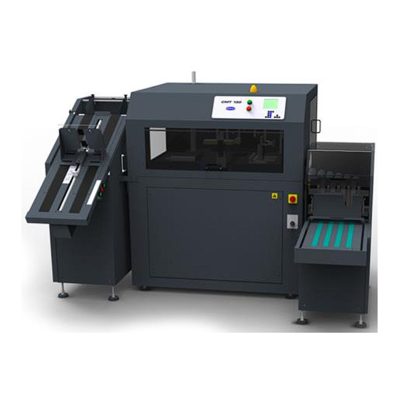
CMT-130
Book Trimmer
Service Manual
Serial Numbers:
12110562 through 15999999, and
130T-B-150000 through 130T-B-169999
This manual covers: Hand-Feed Conveyor, Ad-
vanced In-Feed Conveyor, Cooling Elevator,
and Exit Conveyor.
For Book Pile Feeder, see manual: F.501
For Vertical Stacker, see manual: F.502
CAUTION
Certain components in the CMT 130 are suscep-
tible to damage due to electrostatic discharge.
Observe all ESD procedures to avoid compo-
nent damage.
FX.013B
Issued:
January 2013
Last Revised:
2/2/2017
CMT-130 Book Trimmer
THE CHALLENGE MACHINERY COMPANY
SERIAL No.: ____________________
FX.013B / FEB 2017
Advertisement
Table of Contents

Related Manuals for Challenge CMT-130


Summary of Contents for Challenge CMT-130
- Page 1 THE CHALLENGE MACHINERY COMPANY CMT-130 Book Trimmer Service Manual Serial Numbers: 12110562 through 15999999, and 130T-B-150000 through 130T-B-169999 This manual covers: Hand-Feed Conveyor, Ad- vanced In-Feed Conveyor, Cooling Elevator, and Exit Conveyor. For Book Pile Feeder, see manual: F.501 For Vertical Stacker, see manual: F.502...
-
Page 2: Introduction
ChallengeMachinery.com Products may be unsupported by The Challenge Machinery Company due to age or the unavail- ability of parts from their original manufacturer. No parts or product support will be available to repair or maintain unsupported products. Older products may not be UL listed (if the product does not have a UL label it is not a listed product), and may not comply with applicable installation or ©2002-2017 by The Challenge Machinery Company. -
Page 3: Safety
Read and understand all instructions thoroughly before using the machine. If questions remain, contact your Author- ized Challenge Dealer. Failure to un- derstand the operating instructions may result in personal injury. Only trained and authorized individuals should operate this machine. -
Page 4: Revision Control List
Revision Control List Page Rev. Page Rev. Page Rev. Page Rev. Page Rev. Page Rev. FEB 2017 Introduction CMT 130 Book Trimmer... -
Page 5: Table Of Contents
Table of Contents Title Page Title Page Title Page RAP 2.25 Jogger Cylinder ......... 2-33 BQ 3.3 Burr Marks/Jagged Cover ......3-2 Introduction ............ii RAP 2.26 Gripper Clamp Cylinder ..... 2-34 BQ 3.4 Rectangular Crease Lines ....... 3-3 NOTICE ..............ii RAP 2.27 Gripper Rotator Lock Cylinder ... - Page 6 PL 5.7 Main Assembly 59000 (7/12) ....5-8 PL 5.55 Exit Conv. 56420 (2/3)......5-56 WD 7.16 Interconnection Diagram E-3308-1 ..7-17 PL 5.8 Main Assembly 59000 (8/12) ....5-9 PL 5.56 Exit Conv. 56420 (3/3)......5-57 WD 7.17 Fuse Chart S-1781-193 ..... 7-18 PL 5.9 Main Assembly 59000 (9/12) ....
-
Page 7: About This Manual
RAP 2.x. static discharge. This section contains procedures necessary to The "2" refers to section number in this manual. install the CMT-130 and its accessories. Note Definition: Section 3 – Book Quality Note: A regular note indicates an operating,... -
Page 8: Power Lockout Procedure
Warning Label Symbols Other Symbols Power Lockout Procedure Warning labels are posted throughout the ma- Become familiar with other symbols used in this For maximum safety while making ADJUST- chine to indicate areas where physical injury manual. MENTS or REPAIRS to your machine, lock out may occur. -
Page 9: Service Call Procedures
1. Service Call Procedures Contents 4. If problem is not identified within one hour, Evenings: Xerox CSE contacts C.P. Bourg, Inc. as Title Page Monday-Thurs., 5:00 pm- 8:00 am EST follows: Introduction ............1-1 Phone: 1-508-998-0933 Normal Business Hours: Service Escalation Policy ........1-1 1-508-998-2391 How to Order Parts .......... - Page 10 T&M Time and Material (T&M) is not supported by Xerox Service Offline units only (not connected to printer) Customer Responsibilities: Customer must stock the CMT 130 spare parts kit for each site. Customer must ensure adequate inven- tory of spare parts are maintained on- site at all times.
-
Page 11: Status Indicator Raps
2. Status Indicator RAPs Contents Introduction The status indicator, repair analysis procedures Title Page Title Page (RAPs) provide in-depth troubleshooting RAP 2.1 Fault Entry ..........2-2 RAP 2.42 In-Feed Motors ........2-50 measures. They were designed for thorough RAP 2.2 Final Actions/System Checks ....2-3 RAP 2.43 Elevator Motor ........ -
Page 12: Rap 2.1 Fault Entry
RAP 2.1 Fault Entry Perform RAP 2.5 Input Power and RAP 2.6 This RAP should be performed on every service DC Power to confirm that all power sources call in order to correctly diagnose and trouble- are working properly. If the gripper still is shoot the problem being reported. -
Page 13: Rap 2.2 Final Actions/System Checks
RAP 2.2 Final Actions/System Checks Use the following procedure to ensure accepta- ble machine performance before closing the ser- vice call. Procedure 1. Reinstall all covers. 2. Close all doors. 3. Verify that the accessory machines are lo- cated at their normal operating locations and settings are as described in the installation manual. -
Page 14: Rap 2.3 Faults With Error Messages
GP 6.9 Proximity Sensors is dirty of faulty Book jam between CMT- A book is jammed between the CMT-130 and the input device RAP 2.60 Book Out of Elevator Sensor 130 and input device. (Elevator, Pile Feeder, etc.). Switch off the machine and re- RAP 2.39 Internal Conveyor Motor... - Page 15 Error Messages (continued) Message Description Suggested RAPs Jogger error! OUT when Jogger cylinder was out when it should have been in. Output 18 RAP 2.25 Jogger Cylinder it should be IN is off but input 12 shows jogger extended. RAP 2.47 Jogger Retract Sensor Jogger error! IN when it Jogger cylinder was in when it should have been out.
- Page 16 Error Messages (continued) Message Description Suggested RAPs Motor starter error! OFF Motor starter was off when it should have been on. Output 11 on RAP 2.17 Starter Circuit when it should be on with input 24 off. RAP 2.43 Elevator Motor RAP 2.44 Out-Feed Conveyor Motor RAP 2.25 Jogger Cylinder NO Air Pressure...
- Page 17 Error Messages (continued) Message Description Suggested RAPs Start button held in at The start button or remote cut button is being held in. Either but- Make sure both e-stop buttons are released. power up ton may be faulty. RAP 2.15 Start/Remote Cut Buttons Stop button pressed An e-stop button is pressed or one is faulty.
-
Page 18: Rap 2.4 Other Faults (No Error Message)
RAP 2.4 Other Faults (No Error Mes- sage) Description of Fault Recommended Procedures Trimmer – Machine Fault Machine will not switch on RAP 2.5 Input Power The status light is always on, or never on RAP 2.10 Status Light Console will not illuminate RAP 2.7 Display Backlight RAP 2.5 Input Power Console illuminates but no text is displayed on screen... - Page 19 Other Faults (No Error Message) continued Description of Fault Recommended Procedures Trimmer – Machine Fault (continued) Knife cuts with high impact at bottom of stroke even RAP 2.19 Proportional and Dump Valve when cushioning is set HIGH Knife scrap does not blow into waste bin RAP 2.34 Scrap Air Blast Remote cut button does not work RAP 2.15 Start/Remote Cut Buttons...
- Page 20 Other Faults (No Error Message) continued Description of Fault Recommended Procedures In-Feed Accessory Faults In-feed Conveyor(s) do not run RAP 2.12 Input Door Interlocks Tilt In-feed conveyor tilt operation is faulty RAP 2.38 Tilt In-feed Cylinders RAP 2.56 In-Feed Conv. Book-on-Tilt Sensor RAP 2.42 In-Feed Motors The tilt table on the Tilt In-feed conveyor does not lift RAP 2.38 Tilt In-feed Cylinders...
-
Page 21: Rap 2.5 Input Power
RAP 2.5 Input Power hookup, Figure 2-2. The line voltage should 10. Is there line voltage between wires 3 and 4 meet the following specifications: at the F3 and F4 fuse holders, Figure 2-2? This procedure is used to establish main, AC ... - Page 22 Figure 2-3. Transformer Locations Figure 2-4. T1 Transformer – 60Hz Figure 2-5. T1 & T4 Transformers – 50Hz Figure 2-2. Power Panel Item Locations FEB 2017 2. Status Indicator RAPs 2-12 CMT 130 Book Trimmer...
-
Page 23: Rap 2.6 Dc Power
RAP 2.6 DC Power Check and repair wires 73, 74, 111, and 106. Disconnect main power and replace main This procedure troubleshoots the 5, 15, 24 VDC PWB. Normal power supplies. 7. Is there 12 VAC between wires pairs 50/51 and 51/52 and 24 VAC between 50/52? WARNING Lockout power! Perform the Power Lockout... -
Page 24: Rap 2.7 Display Backlight
RAP 2.7 Display Backlight The backlight comes on when power is switched on. It remains on until a time of inactivity is reached that is equal to the sleep timer setting. Initial Actions The enclosure lights and backlight are powered from the same source (9 VAC). -
Page 25: Rap 2.8 Enclosure Lights
RAP 2.8 Enclosure Lights Output 31 The enclosure lights come on when power is switched on. They remain on until a time of in- activity is reached that is equal to the sleep timer setting. If an individual lamp fails, first replace bulb, then check socket continuity to machine ground. -
Page 26: Rap 2.9 Cooling Fans
RAP 2.9 Cooling Fans Three fans cool the hydraulic system. Two are mounted inside the machine, next to the hydrau- lic power unit. The third fan is located on the rear side of the machine (Figure 2-10). The fans should always be on when the power is switched Initial Actions Switch on the machine to check if all fans are running. -
Page 27: Rap 2.10 Status Light
RAP 2.10 Status Light 4. Disconnect main power and replace the main PWB (REP 4.22 Main PWB Replace- ment). Output 1 The status light remains on when the machine is running normally. It flashes slowly when the ma- chine is in standby mode and flashes rapidly when a fault occurs. -
Page 28: Rap 2.11 Door Interlocks
RAP 2.11 Door Interlocks Disconnect main power and replace the Input 9 main PWB (REP 4.22 Main PWB Re- placement). Door interlocks switches are located on each of the machine’s doors: front, side, and rear, Figure Disconnect main power and replace the 2-12. -
Page 29: Rap 2.12 Input Door Interlocks
RAP 2.12 Input Door Interlocks Check the interlock switches for proper op- eration. Replace as necessary (PL 5.33 El- (Inline models only) evator 56421 (7/7)). 2. Disconnect wire 126 from the main PWB. Input 13 Does the sensor data change to (13-0)? The Tilt In-Feed Conveyor and the Elevator each have a door interlock wired together in se- ries. -
Page 30: Rap 2.13 Interlock Test
RAP 2.13 Interlock Test The interlock switches used in the CMT130 each contain a plunger that is pressed by a door’s hinge rod whenever a door is opened. When the plunger is pressed, the interlock circuit be- comes open and all motion stops. Initial Actions Disconnect main power and remove the top cover in order to access the switches without... -
Page 31: Rap 2.14 Interlock Relay
RAP 2.14 Interlock Relay 4. Switch off the machine. Disconnect all wires at the IR relay. Test continuity of all six con- Disconnect main power and replace the re- tacts in the IR relay. The contacts should be Input 23, Output 7 lay, IR (PL 5.15 Power Panel EE-3306-1 open when the manual actuator tab is not (1/2)). -
Page 32: Rap 2.15 Start/Remote Cut Buttons
RAP 2.15 Start/Remote Cut Buttons Disconnect main power and replace the Input 20 and 22 main PWB (REP 4.22 Main PWB Re- placement). The start button is located on the console. The remote cut button is located at the back of the Go to GP 6.14 Contact Block and check machine. -
Page 33: Rap 2.16 E-Stop/Remote E-Stop Buttons
RAP 2.16 E-Stop/Remote E-Stop But- Go to GP 6.14 Contact Block and check each contact block on each e-stop switch. tons Disconnect main power and replace faulty Input 27 contact blocks (PL 5.1 Main Assembly 59000 (1/12) or PL 5.18 Control Console Either of these buttons stops the hydraulic motor EE-3310). -
Page 34: Rap 2.17 Starter Circuit
RAP 2.17 Starter Circuit 2. Go to RAP 2.16 E-Stop/Remote E-Stop But- tons. Input 23 and 24, Output 7 3. Go to RAP 2.18 Pump Relay. The IR relay enables operation of the gripper 4. Go to RAP 2.14 Interlock Relay. transport, knife and registration movement and 5. -
Page 35: Rap 2.18 Pump Relay
RAP 2.18 Pump Relay 7. Press the green start button. Is output LED 3 switched off? Replace the overload relay, OLH (PL 5.15 Input 24, Output 3 Power Panel EE-3306-1 (1/2)). The pump motor relay (PM) switches on when Disconnect main power and replace the 3. -
Page 36: Rap 2.19 Proportional And Dump Valves
RAP 2.19 Proportional and Dump and 32 switch on before the error message displays? Valves Go to GP 6.13 Hirschmann Connector. Was there a loose or shorted wire in the con- Outputs 10 and 32 nector? Go to RAP 2.6 DC Power and check the 24 VDC power supply. - Page 37 Figure 2-24. Proportional and Dump Valves Figure 2-25. Murr Adapter FEB 2017 CMT 130 Book Trimmer 2-27 2. Status Indicator RAPs...
-
Page 38: Rap 2.20 Cut Valve
RAP 2.20 Cut Valve Disconnect main power and repair the Output 13 24 VDC power supply. After the cut valve is energized, hydraulic fluid is Disconnect main power and replace the routed to the down port of the cut cylinder. The main PWB (REP 4.22 Main PWB Replace- cut valve is located at the left-hand rear of the ment). -
Page 39: Rap 2.21 Shutdown Relay
RAP 2.21 Shutdown Relay Disconnect main power and replace the re- Output 14 lay (PL 5.15 Power Panel EE-3306-1 (1/2)). The shutdown relay provides trimmer shutdown 5. Check the 3rd-party product and its hook-up information to 3rd-party products. When the for the fault. -
Page 40: Rap 2.22 Servo Drive Initialization
RAP 2.22 Servo Drive Initialization 14.) Press and release the "SET" button. 15.) Close the clear gray Plexiglas cover that If you are replacing the servo drive, it must be covers the LED display on the servo initialized after installation. drive. -
Page 41: Rap 2.23 Servo Drive System
RAP 2.23 Servo Drive System Press and release the "MODE" button (first button), " " should ap- Input 11, Outputs “SCR” and “Brake” pear in the display. The servo drive controls the motion of the grip- Press the "UP" button (second button) per transport. -
Page 42: Rap 2.24 Pneumatic Pressure Switch
RAP 2.24 Pneumatic Pressure Switch 5. Short wire 60 to 64. The sensor data screen displays (19-1). Input 19 The pressure switch is located in the left center Disconnect main power and replace the of the power panel. It is activated when input air main PWB (REP 4.22 Main PWB Replace- pressure is greater than 20 psi. -
Page 43: Rap 2.25 Jogger Cylinder
RAP 2.25 Jogger Cylinder 11. Switch off main air. Replace jogger cylinder (PL 5.9 Main As- 12. Re-connect air hoses “P” and “1P” to their Outputs 9 and 18 sembly 59000 (9/12)) initial configuration as shown in Figure 2-36. To register each book, an air cylinder pushes 4. -
Page 44: Rap 2.26 Gripper Clamp Cylinder
RAP 2.26 Gripper Clamp Cylinder Disconnect main power and replace valve Output 27 number 2 (PL 5.21 Pneu. Manifold Asm. 59012-1). The gripper clamps the book through the ma- chine cycle and transports it from station to sta- 5. Electrically activate valve number 2 by short- tion within the machine. -
Page 45: Rap 2.27 Gripper Rotator Lock Cylinder
RAP 2.27 Gripper Rotator Lock Cylin- 3. Disconnect main power and replace the main PWB (REP 4.22 Main PWB Replace- ment). Output 12 The rotator lock cylinder locks the gripper as- sembly into position rotationally. This ensures that the books will be cut squarely each time. The cylinder retracts whenever the gripper as- sembly rotates. -
Page 46: Rap 2.28 Elevator Pusher Cylinder
RAP 2.28 Elevator Pusher Cylinder Disconnect main power and air to replace Output 20 valve number 4 (PL 5.21 Pneu. Manifold Asm. 59012-1). The elevator pusher cylinder feeds the book from the top shelf of the elevator into the trim- 4. -
Page 47: Rap 2.29 Knife Shift Cylinders
RAP 2.29 Knife Shift Cylinders Disconnect main power and air to replace Output 21 valve number 5 (PL 5.21 Pneu. Manifold Asm. 59012-1). The knife shift cylinders shift the knife bar as- sembly from one side to another, allowing the 4. -
Page 48: Rap 2.30 Gripper Lift Cylinder
RAP 2.30 Gripper Lift Cylinder Output 28 The gripper lift is a short air cylinder that lifts the lower gripper plate. It lifts the book above the table surface while the gripper is in motion. Possible Fault Indicators Books have nicks or scuff marks on bot- tom cover Initial Actions Perform GP 6.15 Speed-Control Air Valves. -
Page 49: Rap 2.31 Registration Plate Extend Cylinder
RAP 2.31 Registration Plate Extend 2. Electrically activate valve 7A by shorting wire 116 to wire 74. Does the plate extend? Cylinder Output 17 Disconnect main power and replace valve number 7 (PL 5.21 Pneu. Manifold Asm. The registration plate extends during the jog, 59012-1). -
Page 50: Rap 2.32 Book Lift Air Blast
RAP 2.32 Book Lift Air Blast Disconnect main power and replace valve Output 16 number 7 (PL 5.21 Pneu. Manifold Asm. 59012-1). The book lift air blast jet is mounted on the grip- per assembly, Figure 2-49. The blast creates an 3. -
Page 51: Rap 2.33 Knife Latch Cylinder
RAP 2.33 Knife Latch Cylinder Disconnect main power and replace valve Output 3 number 8 (PL 5.21 Pneu. Manifold Asm. 59012-1). A pneumatic latch prevents the knife assembly from moving down any time the hydraulic motor 4. Disconnect main power and replace the is not running. -
Page 52: Rap 2.34 Scrap Air Blast
RAP 2.34 Scrap Air Blast 4. Disconnect main power and replace the main PWB (REP 4.22 Main PWB Replace- ment). Output 30 Four air jets are mounted on the face of the knife bar. The jets activate when the knife reaches the bottom of the stroke. -
Page 53: Rap 2.35 Book Gate Cylinder
RAP 2.35 Book Gate Cylinder 4. Disconnect main power and replace the main PWB (REP 4.22 Main PWB Replace- ment). Output 23 5. Readjust the flow control valves to slow the The book gate extends and retracts as books movement of the book gate slightly in each travel through the trimmer. -
Page 54: Rap 2.36 Face Jog Cylinder
RAP 2.36 Face Jog Cylinder Disconnect main power and replace valve Outputs 4 and 6 number 12 (PL 5.21 Pneu. Manifold Asm. 59012-1). The face jog extends and rotates into position during the book registration and aids in the book 3. -
Page 55: Rap 2.37 Left And Right Clamp Cylinders
RAP 2.37 Left and Right Clamp Cylin- ders Disconnect main power and replace valve number 13 (PL 5.21 Pneu. Manifold Asm. Outputs 15 & 29 59012-1). Whenever the top of a book is trimmed, air pres- 2. Electrically activate valve number 13 by sure to the left clamp cylinder is turned off and shorting wire 70 to 74 on the main PWB. -
Page 56: Rap 2.38 Tilt In-Feed Cylinders
RAP 2.38 Tilt In-feed Cylinders Disconnect main power and replace the Output 2 main PWB (REP 4.22 Main PWB Replace- ment). While the Tilt In-feed Conveyor is waiting for books, the tilt-table should be in an angled posi- 3. Press and release the e-stop button. tion. -
Page 57: Rap 2.39 Internal Conveyor Motor
RAP 2.39 Internal Conveyor Motor Go to RAP 2.14 Interlock Relay (PL 5.15 Output 22 Power Panel EE-3306-1 (1/2)). The motor that drives the two internal conveyors 4. After the gripper has preset and the pump is located beneath the left-hand conveyor near motor is running, short wire 24 to 37 at the front of the machine (Figure 2-62). -
Page 58: Rap 2.40 Registration Assembly Motor
RAP 2.40 Registration Assembly Mo- 4. Is there 5 VDC between wires 7 and 8 at the encoder wire connector? Output “Mot A” Check for loose or broken wires 7 and 8. The registration assembly is located behind the 5. Is there 5 VDC between wires 7 and 8 at the right-hand conveyor inside the trimmer. -
Page 59: Rap 2.41 Rotary Gripper Motor
RAP 2.41 Rotary Gripper Motor Check for loose or broken wires 7 and 8. Outputs 8, 11, 19 3. Is there 5 VDC between wires 7 and 8 at the A stepper motor is used to rotate the gripper as- main PWB? sembly in order to perform the top and bottom book cuts. -
Page 60: Rap 2.42 In-Feed Motors
RAP 2.42 In-Feed Motors 3. Switch on the machine and measure voltage 3. Disconnect main power and replace the re- between wire 22 and wire 123 at the IR re- lay, SSR3 (PL 5.15 Power Panel EE-3306-1 lay. There should be 0 VAC before pressing (1/2)). -
Page 61: Rap 2.43 Elevator Motor
RAP 2.43 Elevator Motor Press the green start button. Is output LED Procedure (lifts continuously) 26 switched on? 1. Switch on the machine and press the green Output 26 start button. Does output LED 26 switch on for 1-2 seconds, then switch off? The motor is located in the base of the elevator Go to RAP 2.14 Interlock Relay. -
Page 62: Rap 2.44 Out-Feed Conveyor Motor
RAP 2.44 Out-Feed Conveyor Motor 2. Check fuse, F11 (Figure 2-2). Is resistance 7. Disconnect main power and replace the re- is less than 2 Ohms? lay, SSR4 (PL 5.15 Power Panel EE-3306-1 (1/2)). Output 24 The exit conveyor motor only activates when a Replace fuse F11. -
Page 63: Rap 2.45 Knife Latch Sensor
RAP 2.45 Knife Latch Sensor 4. Go to GP 6.9 Proximity Sensors (PL 5.4 Main Assembly 59000 (4/12)). Input 16 The knife latch sensor detects that the latches are disengaged, Figure 2-72. Possible Fault Indicators Knife latch failed to disen- gage is displayed Initial Actions Perform RAP 2.33 Knife Latch Cylinder to vali-... -
Page 64: Rap 2.46 Book In Position Sensor
RAP 2.46 Book in Position Sensor Disconnect main power and replace the Input 4 main PWB (REP 4.22 Main PWB Re- placement). The book in position sensor detects the book in the gripper, Figure 2-73. If a book is lost during Go to GP 6.10 Retro-reflective Sensors (PL a cycle, the machine stops, and an error mes- 5.6 Main Assembly 59000 (6/12)). -
Page 65: Rap 2.47 Jogger Retract Sensor
RAP 2.47 Jogger Retract Sensor Disconnect main power and replace the Input 12 main PWB (REP 4.22 Main PWB Replace- ment). The jogger retract sensor detects that the jogger cylinder is retracted. The jogger must be re- 4. Adjust the sensor by first switching on the tracted before a book can be taken from home machine and press A to enter sensor data position to the jogging station. -
Page 66: Rap 2.48 Registration Preset Sensor
RAP 2.48 Registration Preset Sensor Short wire 15 to wire 64 at the main PWB. Input 26 Does the sensor data change to (26-1)? Each time a new book size is programmed into the machine, the registration presets prior to Disconnect main power and replace the moving into its proper position. -
Page 67: Rap 2.49 Face Jog Sensors
RAP 2.49 Face Jog Sensors Disconnect main power and replace the Inputs 18 and 25 main PWB (REP 4.22 Main PWB Re- placement). The face jog extends and rotates into position during the book registration and aids in the book Disconnect main power and replace the lin- registration process. -
Page 68: Rap 2.50 Rotator Preset Sensor
RAP 2.50 Rotator Preset Sensor Disconnect main power and replace the Input 5 main PWB (REP 4.22 Main PWB Replace- ment). The rotator preset sensor is located on the grip- per assembly as shown in Figure 2-78. The 7. Go to GP 6.9 Proximity Sensors (PL 5.6 sensor determines the home position of the rota- Main Assembly 59000 (6/12)). -
Page 69: Rap 2.51 Knife Position Sensor
RAP 2.51 Knife Position Sensor Go to GP 6.9 Proximity Sensors (PL 5.5 Main Assembly 59000 (5/12)). Input 30 3. Short wire 53 to 64. Does the sensor data This sensor detects when the knife bar assem- screen display (30-1)? bly is shifting from one side to another, and pre- vents a cut from being made unless the knife bar Disconnect main power and replace the... -
Page 70: Rap 2.52 Knife Up Sensor
RAP 2.52 Knife Up Sensor Disconnect main power and replace the Input 32 main PWB (REP 4.22 Main PWB Replace- ment). This sensor detects when the knife assembly reaches its top position. It is mounted to the 4. Go to GP 6.9 Proximity Sensors (PL 5.3 barrel of the hydraulic cylinder, Figure 2-80. -
Page 71: Rap 2.53 Knife Slow-Down Sensor
RAP 2.53 Knife Slow-Down Sensor Disconnect main power and replace the Input 0 main PWB (REP 4.22 Main PWB Replace- ment). The knife down sensor is located inside the rear door and is mounted 1/2” above the table sur- 3. Go to GP 6.9 Proximity Sensors (PL 5.4 face, Figure 2-81. -
Page 72: Rap 2.54 Knife Down Sensor
RAP 2.54 Knife Down Sensor Disconnect main power and replace the Input 29 main PWB (REP 4.22 Main PWB Replace- ment). The knife down sensor is located inside the rear door and is mounted on the table surface, Figure 3. Go to GP 6.9 Proximity Sensors (PL 5.4 2-83. -
Page 73: Rap 2.55 In-Feed Sleep Mode Sensor
RAP 2.55 In-Feed Sleep Mode Sensor Disconnect main power and replace the Input 15 main PWB (REP 4.22 Main PWB Replace- ment). This sensor detects books entering the Tilt In- feed Conveyor. If it detects a book while the 3. Go to GP 6.11 Diffuse Sensors (PL 5.38 Tilt machine is in sleep mode, the computer brings Conveyor 56600 (1/8) or PL 5.46 Tilt Conv. -
Page 74: Rap 2.56 In-Feed Conv. Book-On-Tilt Sensors
RAP 2.56 In-Feed Conv. Book-on-Tilt Sensors Disconnect main power and replace the main PWB (REP 4.22 Main PWB Replace- Input 1 ment). The sensors are located under the tilt table sur- 3. Go to GP 6.10 Retro-reflective Sensors (PL face as shown Figure 2-86. The sensors detect 5.38 Tilt Conveyor 56600 (1/8) or PL 5.46 books as they fall onto the conveyor. -
Page 75: Rap 2.57 Book In Elevator Sensor
RAP 2.57 Book in Elevator Sensor Disconnect main power and replace the Input 2 main PWB (REP 4.22 Main PWB Replace- ment). The book in elevator sensor is mounted at the bottom, left-hand side of the elevator, detecting 3. Go to GP 6.10 Retro-reflective Sensors (PL incoming books, Figure 2-87. -
Page 76: Rap 2.58 Elevator Lift Plate Sensor
RAP 2.58 Elevator Lift Plate Sensor Replace the main PWB (REP 4.22 Main Input 10 PWB Replacement). The sensor is located on the right side of the el- Go to GP 6.9 Proximity Sensors (PL 5.29 El- evator, between the elevator and the trimmer. evator 56421 (3/7) or PL 5.36 Elev. -
Page 77: Rap 2.59 Book At Top Of Elevator Sensor
RAP 2.59 Book at Top of Elevator Check for shorted or disconnected wires within the elevator. Go to GP 6.10 Retro-re- Sensor flective Sensors (PL 5.28 Elevator 56421 (2/7) or PL 5.36 Elev. Electrical EE-2980-1). Input 14 2. Disconnect wire 127 from the power panel. The book at top of elevator sensor detects Does the sensor data display (14-0)? books on the top shelf of the elevator, Figure... -
Page 78: Rap 2.60 Book Out Of Elevator Sensor
RAP 2.60 Book Out of Elevator Sen- Short wire 124 to 64 at the main PWB. Does the sensor data screen display (21- Input 21 The book out of elevator retro-reflective sensor detects books as they move from the elevator Disconnect main power and replace the into the trimmer. -
Page 79: Rap 2.61 Out-Feed Accessory Full Sensor
RAP 2.61 Out-Feed Accessory Full Exit Conveyor: Go to GP 6.11 Diffuse Sen- sors (PL 5.54 Exit Conv. 56420 (1/3) or PL Sensor 5.57 Exit Conv. Elec. EE-2979-3). Input 3 2. Disconnect wire 55. The sensor data screen displays (3-0). During normal operation, the outfeed accessory stops when the “Full”... - Page 80 NOTES FEB 2017 2. Status Indicator RAPs 2-70 CMT 130 Book Trimmer...
-
Page 81: Book Quality
3. Book Quality Contents Title Page BQ 3.1 Burr Marks ..........3-2 BQ 3.2 Jagged Bottom Cover ......3-2 BQ 3.3 Burr Marks/Jagged Cover ....... 3-2 BQ 3.4 Rectangular Crease Lines ....... 3-3 BQ 3.5 Linear Crease Lines ........ 3-3 BQ 3.6 Draw ............ -
Page 82: Bq 3.1 Burr Marks
BQ 3.1 Burr Marks BQ 3.2 Jagged Bottom Cover BQ 3.3 Burr Marks/Jagged Cover Description Description Description Burr marks are found on books cut with a knife Books can appear as though the bottom few A jagged bottom cover may also accompany where the cutting edge has been burred. -
Page 83: Bq 3.4 Rectangular Crease Lines
BQ 3.4 Rectangular Crease Lines BQ 3.5 Linear Crease Lines BQ 3.6 Draw Description Description Description Indentations or crease lines may appear in a Indentations or crease lines may appear in a The cut face appears to have a slope because rectangular pattern in the center of the book. -
Page 84: Bq 3.7 All Sheets Not Cut
BQ 3.7 All Sheets Not Cut BQ 3.8 Book Not Square agent. See ADJ 4.7 Squaring Adjust- ment. Description Description Bottom sheets are not being cut. Book appears as though it was not cut square. Possible Causes The book was allowed to cool with a twisted binding as shown in Figure 3-8. -
Page 85: Repair/Adjustment Procedures
4. Repair/Adjustment Procedures Contents Title Page REP 4.1 Cut Stick Replacement ......4-2 REP 4.2 Knife Replacement ........ 4-3 REP 4.3 Knife Depth Adjustment ......4-6 ADJ 4.4 Lubrication ..........4-7 REP 4.5 Slide Tape ..........4-8 ADJ 4.6 Accuracy Adjustment ......4-9 ADJ 4.7 Squaring Adjustment ...... -
Page 86: Rep 4.1 Cut Stick Replacement
REP 4.1 Cut Stick Replacement came out of the right end of the slot goes into the left end of the slot. If a surface has The cut stick (PL 5.3 Main Assembly 59000 been used twice, rotate the stick to an un- (3/12)) should be changed or rotated with every used surface before reinstalling (Figure 4-3). -
Page 87: Rep 4.2 Knife Replacement
REP 4.2 Knife Replacement 4. Place the knife lifter in position, aligning each lifter handle with the holes from which the two knife bolts were removed in the pre- vious step. Turn the handles clockwise until WARNING the lifter is securely fastened to the knife bar Changing knives can be very dangerous un- (Figure 4-6). - Page 88 from the machine. DO NOT turn the han- 10. Hold the knife lifter with knife at a safe dis- dles any more than what is required to free tance from the body. Other people should WARNING the knife. not be nearby. Carry the lifter to the installa- Knife changing is a ONE PERSON OPERA- tion location.
- Page 89 14. Place 4 knife bolts into the 4 available holes in the knife and use the T-handle wrench to secure them as shown in Figure 4-7. 15. Turn the lifter handles counterclockwise and remove the lifter from the machine. 16. Place 2 knife bolts into the holes from which the knife lifter handles were removed.
-
Page 90: Rep 4.3 Knife Depth Adjustment
REP 4.3 Knife Depth Adjustment and in about 1 second, the cutting mecha- nism will perform a cut cycle. The knife depth requires adjustment after every 9. Open the rear door and check the book. If knife change. The knife depth can also be ad- the bottom cover of the book is not fully cut justed if the knife is not fully cutting through through, set the knife depth deeper by turn-... -
Page 91: Adj 4.4 Lubrication
3-in-1® SAE 20 electric motor oil . 3. Squeeze four pumps of a #2 EP molyb- denum grease (such as Challenge part num- ber: SU-30-103) into each of the two bearing housings underneath the table (Figure 4-10). -
Page 92: Rep 4.5 Slide Tape
REP 4.5 Slide Tape Slide tape is used in the jogging station. The slide tape prevents covers from catching on the mounting screw holes in the jogger plates. The tape should be checked for damage. WARNING Disconnect and lockout power as described in the Power Lockout Procedure on page viii. -
Page 93: Adj 4.6 Accuracy Adjustment
5. If the width (W) dimension is not 6.000” ADJ 4.6 Accuracy Adjustment value into the trim (T) dimension on the Ac- (152.4 mm), enter 6.000 (152.4 mm) into the curacy Adj screen. (Typical values are The accuracy adjustment procedure follows. width (W) dimension. -
Page 94: Adj 4.7 Squaring Adjustment
ADJ 4.7 Squaring Adjustment negative, the screw will need to be turned clockwise. It may be necessary to make an adjustment to 5. To make the adjustment, switch off the main the gripper assembly if books are cutting con- power and switch off the main air valve. Re- sistently out-of-square. -
Page 95: Adj 4.8 Timing And Conveyor Belts
ADJ 4.8 Timing and Conveyor Belts a. Remove the top front enclosure. The timing and conveyor belts should be b. Remove the sheet metal book guides. checked for wear. A belt should be replaced if it is cracked, torn, or fraying excessively. c. -
Page 96: Adj 4.9 External Conveyors Belt Check
ADJ 4.9 External Conveyors Belt h. Replace the timing belt (PL 5.39 Tilt Figure 4-19. Exit Conveyor Example Conveyor 56600 (2/8), PL 5.40 Tilt Con- Check veyor 56600 (3/8), PL 5.43 Tilt Con- The belts of the In-feed, Hand-feed, and Exit veyor 56600 (6/8), or PL 5.55 Exit Conv. -
Page 97: Adj 4.10 Conveyor Belt Adjustment
ADJ 4.10 Conveyor Belt Adjustment Exit Conveyor: The belt cannot be stopped by applying approximately 40 A conveyor belt must be adjusted after replace- pounds of pressure to the top surface ment or removal. It may also require occasional of the belt. -
Page 98: Rep 4.11 Oil / Filter Change
5 gallon change. containers from your authorized Challenge Procedure Dealer using the Challenge part number: S- 1991-3 1. Disconnect and set aside any in-feed acces- sories. 8. Reinstall the filler/breather cap. -
Page 99: Rep 4.12 Air Filter Change
REP 4.12 Air Filter Change 12. The air filter is not hazardous. Dispose of it by conventional means. The air filter should be changed annually. WARNING Disconnect and lockout power as described in the Power Lockout Procedure on page viii. 1. -
Page 100: Adj 4.13 Hydraulic System Pressure
ADJ 4.13 Hydraulic System Pressure Use the following procedure to adjust the system pressure to the recommended operating pres- sure of 1800-2000 PSI. Initial Actions Remove the lower left door in order to gain ac- cess to the hydraulic manifold (Figure 4-24). Loosen the system pressure valve's lock nut. -
Page 101: Adj 4.14 Counterbalance Valve
ADJ 4.14 Counterbalance Valve The knife hydraulic cylinder has a counterbal- ance valve attached to the bottom port, Figure 4-25. The counterbalance valve provides smooth operation of the knife assembly as it moves down. If improperly adjusted, the knife assembly will vibrate as it moves down. Initial Actions Remove the back waste bin. -
Page 102: Adj 4.15 Book Underside Air Lift
ADJ 4.15 Book Underside Air Lift The book underside air lift uses a blast of air to reduce scratching on the bottom cover as the books moves through the machine. The amount of lift may require adjustment depending on the thickness of books being trimmed. -
Page 103: Adj 4.16 Knife Gib Adjustment
ADJ 4.16 Knife Gib Adjustment The knife bar has two gibs that may occasionally require adjustment. There is one gib on each end of each knife bar. Perform this procedure to properly adjust them. Also complete ADJ 4.6 Accuracy Adjustment after adjusting the gibs. Procedure 1. -
Page 104: Adj 4.17 Knife Latch
ADJ 4.17 Knife Latch The proximity sensor on the knife latch may be adjusted according to the following procedure. Procedure 1. Switch on the power to the machine and press the green start button to initialize. 2. Switch off the machine and switch off the main air valve. -
Page 105: Adj 4.18 Clamp Pressure Adjustment
ADJ 4.18 Clamp Pressure Adjustment It is recommended that the clamp pressure be set to the same setting as the main pressure of 80-90 psi. However there may be times when it is desirable to decrease the clamp pressure, such as for books with soft covers or soft spines. Be aware that reducing clamp pressure may af- fect the final cut quality of the books. -
Page 106: Adj 4.19 Gripper Clamp Pressure
ADJ 4.19 Gripper Clamp Pressure Use the following procedure to adjust the gripper clamp pressure to the recommended setting of 0.2 to 0.3 MPa. Initial Actions Check that the air supply is switched on. Re- move the power panel door in order to gain ac- cess to the pneumatic manifold (Figure 4-30). -
Page 107: Adj 4.20 Face Jog Pressure
ADJ 4.20 Face Jog Pressure Use the following procedure to adjust the face jog pressure to the recommended setting of 0.2 to 0.3 MPa. Initial Actions Check that the air supply is switched on. Re- move the power panel door in order to gain ac- cess to the pneumatic manifold (Figure 4-31). -
Page 108: Adj 4.21 Face Jog Adjustment
4. Are the LED’s on both of the two sensors ADJ 4.21 Face Jog Adjustment Use the following procedure to adjust the face jogger. a. Loosen the sensor mounting screw and Initial Actions slide the sensor across its groove until the sensor LED switches on. -
Page 109: Rep 4.22 Main Pwb Replacement
REP 4.22 Main PWB Replacement 9. Disconnect all cable connectors from the main PWB. The following procedure outlines the steps nec- 10. Remove six nuts that mount the PWB to essary to replace the main PWB. EEPROMs on standoffs on the power panel. the main PWB store machine-specific data such as calibration data, jobs, and machine settings. -
Page 110: Adj 4.23 Elevator Pusher Height
ADJ 4.23 Elevator Pusher Height 8. Return the pusher to its home position. 9. Re-install the top cover. The height of the pusher plate in the elevator can be adjusted. The consistency with which 10. Switch on the main air at the main air dis- books are pushed into the trimmer is partially connect valve. -
Page 111: Adj 4.24 Elevator Shelf Synchronization
ADJ 4.24 Elevator Shelf Synchroniza- 9. Tighten the two setscrews in the adjustment hub to lock it in place. tion 10. Repeat this procedure as necessary, until Any time the elevator drive chain or motor is un- the plates are level and the drive chain is mounted, the elevator lift plates will require syn- under tension. - Page 112 NOTES FEB 2017 4. Repair/Adjustment Procedures 4-28 CMT 130 Book Trimmer...
-
Page 113: Parts List
5. Parts List PL 5.42 Tilt Conveyor 56600 (5/8) ..... 5-43 Contents PL 5.43 Tilt Conveyor 56600 (6/8) ..... 5-44 Title Page PL 5.44 Tilt Conveyor 56600 (7/8) ..... 5-45 PL 5.45 Tilt Conveyor 56600 (8/8) ..... 5-46 PL 5.1 Main Assembly 59000 (1/12) ....5-2 PL 5.46 Tilt Conv. -
Page 114: 5.1 Main Assembly 59000 (1/12)
THREADED ROD 56805 CASTER 59010 HYDRAULIC POWER UNIT - 60HZ 1 59010-1 HYDRAULIC POWER UNIT - 50HZ 1 59100 STAND WELDMENT - CMT-130 A-9121 LABEL E-1089-24 CTRL TRANSFORMER - 60HZ E-1089-28 CTRL TRANSFORMER - 50HZ E-1237-2 WIRE NUT - RED... -
Page 115: 5.2 Main Assembly 59000 (2/12)
Item Part Description Qty. PL 5.2 Main Assembly 59000 (2/12) 56005 AIR DISCONNECT VALVE 56014_ PNEUM. FILTER/REGULATOR 56015 AIR FLOW CONTROL - 56016 PANEL NUT 56021 ELEC/PNEUM. PRES. VALVE 56025-1 REGULATOR W/ GAUGE 56863 BULKHEAD FITTING 59012-1 PNEUMATIC MANIFOLD ASM H-6406-608 BRASS PIPE NIPPLE - CLOSE H-6423-5... -
Page 116: 5.3 Main Assembly 59000 (3/12)
Item Part Description Qty. PL 5.3 Main Assembly 59000 (3/12) 44077 BRACKET - HYDRAULIC UP PROX 1 56213 DUAL ROD AIR CYLINDER 56239-1 1-3/4" ROD WIPER 56252-1 COUNTER BALANCE VALVE ASM 1 59001 TABLE 59002 ARCH 59003 BASE 59007 LOWER PULL-DOWN BAR 59020 HYD. -
Page 117: 5.4 Main Assembly 59000 (4/12)
Item Part Description Qty. PL 5.4 Main Assembly 59000 (4/12) 8815-1 WASHER - KNIFE SCREWS 56256 GIB INSERT 56393 PROXIMITY BLOCK 56554 PROX. SWITCH RETAINER 59006 RAMP 59024 KNIFE BAR LIFTER BLOCK 59025 KNIFE BAR LIFTER SPRING 59026 KNIFE BAR BEARING BLOCK 59028 KNIFE LATCH PLATE 59031... -
Page 118: 5.5 Main Assembly 59000 (5/12)
Item Part Description Qty. PL 5.5 Main Assembly 59000 (5/12) 6609-2 TEFLON PLUG 56194 BEARING 56211 ROLLER BEARING W/ SEALS 56215 SPACER 56231 KNIFE HEIGHT ADJ. ROD - 16" 56232 LOWER ADJ. PIECE 56234 ADJ. KNOB BLOCK 56255 GIB PLATE 56256 GIB INSERT 56260... -
Page 119: 5.6 Main Assembly 59000 (6/12)
Item Part Description Qty. PL 5.6 Main Assembly 59000 (6/12) 11288-38 WASHER/SPACER 47053-1 COUPLING 47136-17 SPRING 56066-2 TIMING PULLEY - 15 GROOVE XL 59017 GRIPPER LIFT CYLINDER 59018 RAIL 59019 CASSETTE 59037 RAIL PLATE 59038 TRANSPORT PLATE 59079 PROXIMITY SENSOR BRACKET 59080 ROTARY LOCK DISK 59081... -
Page 120: 5.7 Main Assembly 59000 (7/12)
Item Part Description Qty. PL 5.7 Main Assembly 59000 (7/12) 59013 GRIPPER BOTTOM PLATE 59014 GRIPPER BACK PLATE 59015 GRIPPER TOP PLATE 59016 AIR CYLINDER - GRIPPER 59047 AIR FITTING BRACKET 59083 GRIPPER MOUNTING BLOCK 59153-1 GRIPPER CLAMP PAD 59313 SHIM - GRIPPER H-6909-406 SCREW - 1/4-20 X 3/4"... -
Page 121: 5.8 Main Assembly 59000 (8/12)
Item Part Description Qty. PL 5.8 Main Assembly 59000 (8/12) 56066-1 TIMING PULLEY- 15 GROOVE XL 56067-1 IDLER PULLEY 56071-2 IDLER PULLEY 56565 MOTOR - LINEAR DRIVE 59036-07850 TIMING BELT - 78-1/2" 59049 CROSS BRACKET 59071 BELT GUARD/CABLE TRACK 59072 CABLE CARRIER 59092 PROXIMITY BRACKET... -
Page 122: 5.9 Main Assembly 59000 (9/12)
Qty. PL 5.9 Main Assembly 59000 (9/12) 35049-1 SPRING 56075 JOGGER PLATE SPRING 56076 FLOATING GUIDE 56311-3 REGISTRATION ASM - CMT-130 56331-3 JOGGER PLATE 56357-1 JOGGER CYLINDER 56368 REG SQUARING BLOCK 56523-1000 2" WIDE P.E. TAPE - 10" LONG 56566... -
Page 123: 5.10 Main Assembly 59000 (10/12)
59053 CHUTE SUPPORT 59056 REAR DOOR 59057 DOOR HINGE ROD, 51-1/4" 59061 REAR WINDOW PANEL 59070 KNIFE LIFTER ASM - CMT-130 1 E-866-9 POSITIVE ACTION MICROSW E-1152-99 STANDOFF H-6423-#10 NUT - #10-24 HEX KEP H-6423-#4 NUT - #4-40 HEX KEP... -
Page 124: 5.11 Main Assembly 59000 (11/12)
PL 5.11 Main Assembly 59000 (11/12) Item Part Description Qty. 11288-36 WASHER/SPACER 13940-1 HANDLE 56180-6 REFL. TAPE- 1" WIDE X 9" LONG 59030 CONSOLE ASM - CONTROL 59035 DOOR BRACKET 59055 DOOR HINGE ROD, 40-1/2" 59058 DOOR HINGE ROD, 21-1/2" 59059 RH DOOR 59063... -
Page 125: 5.12 Main Assembly 59000 (12/12)
Item Part Description Qty. PL 5.12 Main Assembly 59000 (12/12) 41058 WASTE BIN 56180-6 REFL TAPE- 1" W X 9" L 59060 LOWER COVER 59062 TOP COVER 59064 WINDOW PANEL 59157 ADJ HANDLE COVER E-1152-61 STANDOFF H-6423-4 NUT - 1/4-20 HEX KEP H-6910-102404SS SCR - #10-24 X 1/2 BUT. -
Page 126: 5.13 Registration Asm. 56311-3
Item Part Description Qty. PL 5.13 Registration Asm. 56311-3 56075 JOGGER PLATE SPRING 56076 FLOATING GUIDE 56310 LEADSCREW NUT 59301 REGISTRATION BRACKET 59303 RAIL 59304 CASSETTE 59305 PUSHER BRACKET 59307 ENCODER BRACKET 59308 BOOK STOP BLOCK 59309 AIR CYLINDER - GUIDED 59310 LEADSCREW BRACKET 59311... -
Page 127: 5.14 Conveyor Drive 56374-1
Item Part Description Qty. PL 5.14 Conveyor Drive 56374-1 56346 TIMING PULLEY- 56 GROOVE 56375 MOTOR BRACKET WELDMENT E-1165-7 BRAKE E-1600-163 GEAR MOTOR E-2181-4 CAPACITOR E-2626-3 TERMINAL STRIP (3P) H-6918-44004 SCREW - #4-40 X 1/2 SOC HD H-6918-63206 SCREW - #6-32 X 3/4 SOC HD H-6990-103204 SCREW - #10-32 X 1/2 HEX HD H-7321-#4 WASHER - #4 SAE PLAIN... -
Page 128: 5.15 Power Panel Ee-3306-1 (1/2)
Item Part Description Qty. PL 5.15 Power Panel EE-3306-1 (1/2) 56864 PANEL - POWER E-2742-5 TRANS. - 120V PRIM., 16V & 24V SEC. (T2) Components E-2742-15 TRANS. - 120V PRIM., 9V/19V/28V SEC. (T3) E-2805-2 STARTER - RELAYS, "PM" AND "IR" E-2376-2 AUXILIARY CONTACT - STARTER, N.O. -
Page 129: 5.16 Power Panel Ee-3306-1 (2/2)
Item Part Description;Wire Numbers PL 5.16 Power Panel EE-3306-1 (2/2) E-2805-2 STARTER - RELAYS, "PM" AND "IR" E-2376-2 AUXILIARY CONTACT - STARTER, N.O. Wiring Detail EE-2973-10 PROX ASM. - KNIFE POSITION (KP);63,64,53 EE-3270-3 PROX. ASM. - GRIPPER FOR. LIMIT (GF);73,74 & 101 EE-2973-8 PROX. -
Page 130: 5.17 Power Panel - 50Hz Ee-3310
PL 5.17 Power Panel – 50Hz EE-3310 Item Part Description Qty. E-2742-16 TRANSF. - 380-415V PRIMARY (T4) E-2441-13 RELAY - OVERLOAD, 7.5A TO 11A H-6918-404 SCREW - 1/4-20 X 1/2 SOC. HD H-7324-8 WASHER - 1/4 INT. TOOTHLOCK H-7321-4 WASHER - 1/4 FLAT E-1089-28 TRANSF. -
Page 131: 5.18 Control Console Ee-3310
Item Part Description Qty. PL 5.18 Control Console EE-3310 59030 CONTROL CONSOLE - CMT 130 43066 STRAIN RELIEF - RIBBON CABLE EE-3439 BACKER BOARD ASM - LCD DISP E-1198-15 RESISTOR - 2.2K 3W METAL OXIDE EE-2855-1 RIBBON CABLE ASM. - DISPLAY EE-2855 RIBBON CABLE ASM. -
Page 132: 5.19 Pneumatic Diag. 59000-P (1/2)
Item Part Description Qty. PL 5.19 Pneumatic Diag. 59000-P (1/2) P-303 1/4" O.D. P.E. TUBING (SOLID BLUE) P-303-1 1/4" O.D. P.U. TUBING (TRANS. BLUE) P-303-2 3/8" O.D. P.E. TUBING (SOLID BLUE) P-303-4 3/8" O.D. P.U. TUBING (TRANS. BLUE) 56668 COLLET COVER - RED P-516 CONNECTOR (1/4 MALE SHUT-OFF) FEB 2017... -
Page 133: 5.20 Pneumatic Diag. 59000-P (2/2)
Item Part Description Qty. PL 5.20 Pneumatic Diag. 59000-P (2/2) P-303 1/4" O.D. P.E. TUBING (SOLID BLUE) P-303-1 1/4" O.D. P.U. TUBING (TRANS. BLUE) P-510-4 AIR FLOW REGULATOR - 1/4" TUBE P-508-4 UNION "Y" - 1/4 TUBE DIA. P-318 PLUG P-516 PUSH-IN CONN. -
Page 134: 5.21 Pneu. Manifold Asm. 59012-1
Item Part Description Qty. PL 5.21 Pneu. Manifold Asm. 59012-1 56009 VALVE - 2 POSITION 56011 VALVE - 3 POS., EXH. CENTER 56011-2 VALVE - 3 POS., PRESS. CENTER 1 56012 REGULATOR - MANIFOLD 56013 INDIVIDUAL SUPPLY SPACER 59012-1-M MANIFOLD - 13 STATION FEB 2017 5. -
Page 135: Pl 5.22 Hydraulic Power Unit 59010
Item Part Description Qty. PL 5.22 Hydraulic Power Unit 59010 13946 GASKET (60 Hz) 13947 TANK GASKET 44104 HYDRAULIC TANK 44105 TANK COVER 59011 MANIFOLD ASSEMBLY E-1600-181 MOTOR H-338 DIFFUSER H-226-2 FILTER HEAD- 'O' RING PORTS H-227-1 FILTER H-230-4 ELBOW- ORING TO TUBE H-236-4 ADAPTER - 'O' RING TO TUBE H-238-4... -
Page 136: 5.23 Hydraulic Power Unit 59010-1
Item Part Description Qty. PL 5.23 Hydraulic Power Unit 59010-1 13946 GASKET (50 Hz) 13947 TANK GASKET 44104 HYDRAULIC TANK 44105 TANK COVER 59011 MANIFOLD ASSEMBLY E-1600-183 MOTOR H-338 DIFFUSER H-387 PUMP H-226-2 FILTER HEAD- 'O' RING PORTS H-227-1 FILTER H-230-4 ELBOW- ORING TO TUBE H-236-4... -
Page 137: Pl 5.24 Manifold Assembly 59011
Item Part Description Qty. PL 5.24 Manifold Assembly 59011 56701 HYDRAULIC MANIFOLD 56703 SOLENOID VALVE - FLOW CTRL E-1069-19 24V DC COIL E-1069-23 COIL H-427 SAE PLUG H-517 MANIFOLD SUBPLATE ASM H-568 CAVITY PLUG H-200-2 SOLENOID VALVE - DIRECTION H-200-3 SOLENOID VALVE - DUMP H-230-3 ELBOW- ORING TO TUBE... -
Page 138: Pl 5.25 Hydraulic Schem. 59010-S
Item Part Description Qty. PL 5.25 Hydraulic Schem. 59010-S H-203-26 SYSTEM RELIEF VALVE 56703 SOLENOID VALVE - FLOW CTRL E-1069-19 24V DC COIL E-1069-23 COIL H-200-2 SOLENOID VALVE - DIRECTION H-200-3 SOLENOID VALVE - DUMP FEB 2017 5. Parts List 5-26 CMT 130 Book Trimmer... - Page 139 Item Part Description Qty. PL 5.26 Manifold Sub-Plate H-517 H-203-26 SYSTEM RELIEF VALVE 8P-629-3 GAGE - 0-3000 PSI H-518 TUBE ASM. - PRESSURE GAGE DTS-0345-4 MANIFOLD SUBPLATE H-427-5 PLUG - #6 "O" RING (9/16-18) H-233-1 FITTING - NPT TO "O" RING H-236-3 FTNG - #6 "O"...
-
Page 140: 5.27 Elevator 56421 (1/7)
Item Part Description Qty. PL 5.27 Elevator 56421 (1/7) 51036 FOOT 56442 BASE 56456 THREADED ROD 56540 TERMINAL STRIP BRACKET 56805 CASTER E-519 CONDUIT LOCKNUT E-2450-4 CABLE PIGTAIL- SPOOL MON. E-2451-4 CABLE- MINI-LINE CONNECTOR E-2626-12 TERMINAL STRIP (12P) H-6424-8 NUT - 1/2-13 HEX JAM H-6910-63204 SCREW - #6-32 X 1/2 BUT HD H-6913-406... -
Page 141: 5.28 Elevator 56421 (2/7)
Item Part Description Qty. PL 5.28 Elevator 56421 (2/7) 56451 RODLESS BAND CYLINDER 56453 WELDMENT - PUSHER 56455 PUSHER 56483 PUSHER ASSEMBLY E-866-4 MICROSWITCH EE-2947-10 PROX. ASM. - TOP OF ELEV. H-6423-#4 NUT - #4-40 HEX KEP H-6423-#6 NUT - #6-32 HEX KEP H-6910-102403 SCREW - #10-24 X 3/8 BUT HD H-6918-44006 SCREW - #4-40 X 3/4 SOC HD... -
Page 142: 5.29 Elevator 56421 (3/7)
Item Part Description Qty. PL 5.29 Elevator 56421 (3/7) 56435 SIDE FRAME 56439 FLANGE BEARING 56458 BEARING BLOCK ASSEMBLY 56474 TENSIONING BLOCK 56488 TIE BAR 56551 LIFT PLATE PROX. BRACKET 47264-2101 POLYETHYLENE TAPE- 3/8 WIDE 4 E-2626-3 TERMINAL STRIP (3P) EE-2973-3 PROX. -
Page 143: 5.30 Elevator 56421 (4/7)
Item Part Description Qty. PL 5.30 Elevator 56421 (4/7) 56423 SPROCKET 56424 LIFTER CHAIN 56425 LIFTER AXLE 56438 LIFTER PLATE 56443 LIFTER AXLE 56464 BRACKET 56534 SENSOR BRACKET 56541 COUPLING 56180-2 REFL TAPE - 1" W X 1" L EE-2947-7 PROX. -
Page 144: 5.31 Elevator 56421 (5/7)
Item Part Description Qty. PL 5.31 Elevator 56421 (5/7) 56432 SPROCKET 56440 SPROCKET 56441 LOWER BRACE 56446 IDLER ASM 56448 DRIVE CHAIN 56478 TAPER LOCK SPROCKET 56489 SIDE COVER BRACKET E-1152-82 STANDOFF E-1165-7 BRAKE E-1600-162 GEAR MOTOR H-6423-4 NUT - 1/4-20 HEX KEP H-6910-404 SCREW - 1/4-20 X 1/2 BUT HD H-6913-406... -
Page 145: 5.32 Elevator 56421 (6/7)
Item Part Description Qty. PL 5.32 Elevator 56421 (6/7) 14050 SERIAL PLATE 56080 MOUNTING BRACKET 56422 COVER MOUNTING BRACKET 56459 REAR COVER 56460 SIDE COVER 56462 TOP COVER 56496 INSIDE COVER 56545 R.H. FRONT RETAINER 56546 L.H. FRONT RETAINER 56547 R.H. -
Page 146: 5.33 Elevator 56421 (7/7)
Item Part Description Qty. PL 5.33 Elevator 56421 (7/7) 38029 KNOB 56536 HINGE BLOCK 56538 HINGE ROD 56539 KEEPER BRACKET 56671 SWITCH COVER 56853 GRABBER DOOR CATCH 56481-1 ELEVATOR COVER 56535-1 ELEVATOR DOOR E-866-9 POSITIVE ACTION MICROSW. H-6423-#4 NUT - #4-40 HEX KEP H-6423-#8 NUT - #8-32 HEX KEP H-6423-#10... -
Page 147: Pl 5.34 Idler 56446
Item Part Description Qty. PL 5.34 Idler 56446 56444 IDLER BRACKET 56445 IDLER PIN 56447 IDLER SPROCKET H-6424-8 NUT - 1/2-13 HEX JAM H-7324-16 WASHER - 1/2 INT TOOTH S-1073-50 RETAINING RING FEB 2017 CMT 130 Book Trimmer 5-35 5. Parts List... -
Page 148: Pl 5.35 Pusher 56483
Item Part Description Qty. PL 5.35 Pusher 56483 56417 PUSHER PLATE 56491 BRUSH HOLDER 56484-303 BRUSH H-6918-63203 SCREW - #6-32 X 3/8 SOC HD H-7324-#6 WASHER - #6 INT TOOTH FEB 2017 5. Parts List 5-36 CMT 130 Book Trimmer... -
Page 149: 5.36 Elev. Electrical Ee-2980-1
Item Part Description Qty. PL 5.36 Elev. Electrical EE-2980-1 E-2626-12 TERM STRIP - 12 TERM EE-2973-3 PROX. ASM. - LIFT PLATE EE-3086 CABLE ASM. - LIMIT SWITCH 1 E-2450-4 CABLE PIGTAIL - 7 PIN MALE E-519 CONDUIT LOCKNUT, 1/2" EE-2947-7 PHOTO-SW. -
Page 150: Pl 5.37 Elev. Pneumatics 56421-P
Item Part Description Qty. PL 5.37 Elev. Pneumatics 56421-P P-303 1/4" O.D. PE TUBING (SOLID BLUE) 14FT P-510-4 AIR FLOW REG. - 1/4" TUBE P-515 PUSH-IN CONN. (1/4 FEM) REF. FEB 2017 5. Parts List 5-38 CMT 130 Book Trimmer... -
Page 151: 5.38 Tilt Conveyor 56600 (1/8)
Item Part Description Qty. PL 5.38 Tilt Conveyor 56600 (1/8) 14050 SERIAL PLATE 56410 LEVELING PAD 56549 56601 CONVEYOR CASE 56665 PNEUMATIC VALVE ASM 56340-1 CONV. DRIVE ASM - 56 GROOVE 1 E-519 CONDUIT LOCKNUT E-2450-1 CABLE PIGTAIL- SPOOL MON. E-2450-2 CABLE PIGTAIL- SPOOL MON. -
Page 152: 5.39 Tilt Conveyor 56600 (2/8)
Item Part Description Qty. PL 5.39 Tilt Conveyor 56600 (2/8) 7909 TIMING BELT- 220XL037 56405 TENSIONER BLOCK 56613 DRIVE ASM 56614 IDLER ASM 56651 ENDLESS BELT - TILT CONV 56606-1 WELDMENT - TILT FRAME H-6910-102404 SCREW - #10-24 X 1/2 BUT HD H-6913-102408 SCREW - #10-24 X 1 HEX HD H-6938-102404 SCREW - #10-24 X 1/4 CUP SET H-7324-#10... -
Page 153: 5.40 Tilt Conveyor 56600 (3/8)
Item Part Description Qty. PL 5.40 Tilt Conveyor 56600 (3/8) 56404 DRIVE ASM 56405 TENSIONER BLOCK 56406 IDLER ASM 56449 TIMING BELT- 290XL037 56602 FRAME 56180-2 REFLECTIVE TAPE - 1" W X 1" L 56610-1 ENDLESS BELT - BINDER CONV H-6910-102404 SCREW - #10-24 X 1/2 BUT HD H-6913-102408 SCREW - #10-24 X 1 HEX HD H-6938-102404 SCREW - #10-24 X 1/4 CUP SET... -
Page 154: 5.41 Tilt Conveyor 56600 (4/8)
Item Part Description Qty. PL 5.41 Tilt Conveyor 56600 (4/8) 56604 TILT CROSS BAR ASSEMBLY 56618 BEARING BLOCK ASM. - RH 56620 LINK ASM 56621 LOWER LINK 56622 AXLE 56623 PUSH ROD 56633 LOWER CYLINDER MOUNT ROD 56634 AIR CYLINDER 56684 LIMIT SWITCH BRACKET 56618-1... -
Page 155: 5.42 Tilt Conveyor 56600 (5/8)
Item Part Description Qty. PL 5.42 Tilt Conveyor 56600 (5/8) 7909 TIMING BELT- 220XL037 56346 TIMING PULLEY- 56 GROOVE 56605 TILT HINGE ROD 56612 HINGE ASSEMBLY 56632 BOOK STOP 11288-5 WASHER/SPACER 56180-1 REFL TAPE - 1" W X 1-1/2" L E-1600-163 GEAR MOTOR E-2181-4... -
Page 156: 5.43 Tilt Conveyor 56600 (6/8)
Item Part Description Qty. PL 5.43 Tilt Conveyor 56600 (6/8) 56346 TIMING PULLEY- 56 GROOVE 56638 IDLER ROD 56640 MOTOR GUARD 56644 ENDLESS BELT 56666 BELT GUARD 56669 PULLEY 56681 COVER 56564-1 TIMING BELT- 240XL037 56641-1 DRIVE ROLLER ASM 56656-1 FRAME WELDMENT 56683-1 BELT GUARD... -
Page 157: 5.44 Tilt Conveyor 56600 (7/8)
Item Part Description Qty. PL 5.44 Tilt Conveyor 56600 (7/8) 56635 FRONT FRAME BAR 56636 REAR FRAME BAR 56637 TIE BAR 56646 DOOR HINGE ROD 56658 TIE ROD 56659 TIE ROD 56660 SUPPORT BLOCK 56661 SUPPORT BLOCK 56663 LINK 56664 SWITCH BRACKET 56670 LEVELING FOOT ASSEMBLY... -
Page 158: 5.45 Tilt Conveyor 56600 (8/8)
Item Part Description Qty. PL 5.45 Tilt Conveyor 56600 (8/8) 41074 POLYURETHANE DOT 56645 LH COVER 56647 RH COVER 56648 GUARD 56649 FRONT COVER 56650 TOP COVER 56657 HANDLE W/ HDW 56685 END COVER E-1152-61 STANDOFF H-6910-404 SCREW - 1/4-20 X 1/2 BUT HD H-6910-102404 SCREW - #10-24 X 1/2 BUT HD H-7324-8 WASHER - 1/4 INT TOOTH... -
Page 159: 5.46 Tilt Conv. Elec. Ee-2993-3
Item Part Description Qty. PL 5.46 Tilt Conv. Elec. EE-2993-3 E-1214-59 CONN- #10 INS. LOCK. FORK E-1214-65 CONN- 1/4" FULLY INS. QD E-709-R WIRE - #18 GA. RED 16" (#131) E-709-R WIRE - #18 GA. RED 15" (#26) E-709-R WIRE - #18 GA. RED 16" (#26) E-709-R WIRE - #18 GA. -
Page 160: Pl 5.47 Tilt Conv. Pneum. 56600-P
Item Part Description Qty. PL 5.47 Tilt Conv. Pneum. 56600-P P-303 1/4" O.D. PE TUBING (SOLID BLUE) FEB 2017 5. Parts List 5-48 CMT 130 Book Trimmer... -
Page 161: 5.48 Long Hand-Feed Conv. 56413 (1/3)
Item Part Description Qty. PL 5.48 Long Hand-Feed Conv. 56413 56410 LEVELING PAD (1/3) 56419 56463 LEG BRACE 56340-2 CONVEYOR DRIVE ASM 56409-1 CONVEYOR CASE E-519 CONDUIT LOCKNUT E-2450-1 CABLE PIGTAIL- SPOOL MON. E-2626-6 TERMINAL STRIP (6P) H-6910-404 SCREW - 1/4-20 X 1/2 BUT HD H-6910-604 SCREW - 3/8-16 X 1/2 BUT HD H-6913-404... -
Page 162: 5.49 Long Hand-Feed Conv. 56413 (2/3)
Item Part Description Qty. PL 5.49 Long Hand-Feed Conv. 56413 56404 DRIVE ASM (2/3) 56405 TENSIONER BLOCK 56406 IDLER ASM 56544 ENDLESS BELT- EXT. CONV. 56564 TIMING BELT- 250XL037 56426-1 FRAME H-6910-102404 SCREW - #10-24 X 1/2 BUT HD H-6918-102408 SCREW - #10-24 X 1 SOC HD H-6938-102404 SCREW - #10-24 X 1/4 CUP SET H-7324-#10 WASHER - #10 INT TOOTH... -
Page 163: 5.50 Long Hand-Feed Conv. 56413 (3/3)
Item Part Description Qty. PL 5.50 Long Hand-Feed Conv. 56413 14050 SERIAL PLATE (3/3) 56412 END COVER 56416 CONVEYOR MOUNT BRACKET 56467 CONVEYOR COVER 56479 END COVER 59203 INFEED BOOK GUIDE 56426-1 FRAME E-2196-11 HOLE PLUG H-6910-404 SCREW - 1/4-20 X 1/2 BUT HD H-6910-102404 SCREW - #10-24 X 1/2 BUT HD H-7321-4 WASHER - 1/4 SAE PLAIN... -
Page 164: 5.51 Long Hand-Feed Electrical Ee-2985-1
Item Part Description Qty. PL 5.51 Long Hand-Feed Electrical E-2626-5 TERMINAL STRIP - 5 TERM EE-2985-1 E-2450-1 CABLE PIGTAIL - 5 PIN MALE E-519 CONDUIT LOCKNUT - 1/2" E-1214-49 CONN. - 1/4 FULLY INS. Q.D. E-1214-59 CONN. - #10 INS. LOCK FORK H-6918-63206 SCREW - #6-32x3/4 SOC HD H-7324-#6... -
Page 165: Pl 5.52 Std. Hand-Feed Conv. 59200
Item Part Description Qty. PL 5.52 Std. Hand-feed Conv. 59200 56563 TIMING PULLEY- 20 GROOVE 59048 TIMING BELT - 110XL037 59066 ROLLER ASSEMBLY 59201 INFEED CASE 59202 ENDLESS BELT 59203 INFEED BOOK GUIDE 59205 ROLLER ASSEMBLY 59207 INFEED BOTTOM COVER E-519 CONDUIT LOCKNUT E-530-15... -
Page 166: 5.53 Std Hand-Feed Elec. Ee-3342
PL 5.53 Std Hand-Feed Elec. EE-3342 FEB 2017 5. Parts List 5-54 CMT 130 Book Trimmer... -
Page 167: 5.54 Exit Conv. 56420 (1/3)
Item Part Description Qty. PL 5.54 Exit Conv. 56420 (1/3) 56410 LEVELING PAD 56419 56434 TRAY WELDMENT 56463 LEG BRACE 35126-4 KNOB 56340-2 CONVEYOR DRIVE ASM 56409-1 CONVEYOR CASE E-519 CONDUIT LOCKNUT E-1243-2 RELAY SOCKET E-2228-1 RELAY- TIME DELAY E-2450-3 CABLE PIGTAIL- SPOOL MON. -
Page 168: 5.55 Exit Conv. 56420 (2/3)
Item Part Description Qty. PL 5.55 Exit Conv. 56420 (2/3) 56404 DRIVE ASM 56405 TENSIONER BLOCK 56406 IDLER ASM 56544 ENDLESS BELT- EXT. CONV. 56564 TIMING BELT- 250XL037 56426-1 FRAME H-6910-102404 SCREW - #10-24 X 1/2 BUT HD H-6918-102408 SCREW - #10-24 X 1 SOC HD H-6938-102404 SCREW - #10-24 X 1/4 CUP SET H-7324-#10 WASHER - #10 INT TOOTH... -
Page 169: 5.56 Exit Conv. 56420 (3/3)
Item Part Description Qty. PL 5.56 Exit Conv. 56420 (3/3) 14050 SERIAL PLATE 56416 CONVEYOR MOUNT BRACKET 56465 PULLEY COVER 56467 CONVEYOR COVER 56479 END COVER 56503 ROLLER COVER 56426-1 FRAME E-2196-11 HOLE PLUG H-6910-404 SCREW - 1/4-20 X 1/2 BUT HD H-6910-102404 SCREW - #10-24 X 1/2 BUT HD H-7321-4 WASHER - 1/4 SAE PLAIN... -
Page 170: 5.57 Exit Conv. Elec. Ee-2979-3
Item Part Description Qty. PL 5.57 Exit Conv. Elec. EE-2979-3 E-2626-5 TERMINAL STRIP - 5 TERM E-1243-2 SOCKET - RELAY E-2228-1 RELAY - TIME DELAY E-2450-3 CABLE PIGTAIL - 6 PIN MALE E-519 CONDUIT LOCKNUT - 1/2" EE-2947-5 PHOTO-SWITCH ASM. E-1214-59 CONNECTOR- #10 INS. -
Page 171: 5.58 Conveyor Drive Asm. 56340-1
Item Part Description Qty. PL 5.58 Conveyor Drive Asm. 56340-1 56346 TIMING PULLEY- 56 GROOVE 56338-1 MOTOR BRACKET E-1600-163 GEAR MOTOR E-2181-4 CAPACITOR E-2626-3 TERMINAL STRIP (3P) H-6918-44004 SCREW - #4-40 X 1/2 SOC HD H-6918-63206 SCREW - #6-32 X 3/4 SOC HD H-6918-102404 SCREW - #10-24 X 1/2 SOC HD H-6990-103204 SCREW - #10-32 X 1/2 HEX HD H-7321-#10... -
Page 172: 5.59 Conveyor Drive Asm. 56340-2
Item Part Description Qty. PL 5.59 Conveyor Drive Asm. 56340-2 56563 TIMING PULLEY- 20 GROOVE 56338-1 MOTOR BRACKET E-1600-163 GEAR MOTOR E-2181-4 CAPACITOR E-2626-3 TERMINAL STRIP (3P) H-6918-44004 SCREW - #4-40 X 1/2 SOC HD H-6918-63206 SCREW - #6-32 X 3/4 SOC HD H-6918-102404 SCREW - #10-24 X 1/2 SOC HD H-6990-103204 SCREW - #10-32 X 1/2 HEX HD H-7321-#10... -
Page 173: General Procedures/Information
6. General Procedures/Information Contents Title Page GP 6.1 Retrieve Recent Error Messages .... 6-2 GP 6.2 Input Diagnostics (Sensor Data)....6-3 GP 6.3 Output Diagnostics ........6-5 GP 6.4 Input/Output LEDs ........6-7 GP 6.5 Input Testing ........... 6-8 GP 6.6 Output Testing ......... 6-9 GP 6.7 Software Upgrade/Replacement ... -
Page 174: Gp 6.1 Retrieve Recent Error Messages
GP 6.1 Retrieve Recent Error Mes- sages It may be helpful to see the most recent error messages. If there are currently no error mes- sages on the screen, the 5 most recent error messages can be viewed by performing the fol- lowing procedure: 1. -
Page 175: Gp 6.2 Input Diagnostics (Sensor Data)
GP 6.2 Input Diagnostics (Sensor the following page for a list of inputs and as- sociated RAPs. S e n s o r d a t a Data) 4. To enter sensor data screen with the hy- Sensors and switches throughout the CMT 130 0 - 0 1 - 0 2 - 0... - Page 176 Input States (at Idle) Idle State Idle State Input Description Associated RAP (Motor OFF) (Motor ON) Knife slow down sensor RAP 2.53 Knife Slow-Down Sensor In-feed Conveyor book on tilt sensor RAP 2.56 In-Feed Conv. Book-on-Tilt Sensor Book in elevator sensor RAP 2.57 Book in Elevator Sensor Out-Feed Conveyor sensor RAP 2.61 Out-Feed Accessory Full Sensor...
-
Page 177: Gp 6.3 Output Diagnostics
GP 6.3 Output Diagnostics the following page for a list of outputs and associated RAPs. O u t p u t d a t a Output data is either an on or off command sent 4. To manually toggle an output on or off, key to an output device such as a motor or valve 0 >... - Page 178 Output States (Idle) Idle State Output Description Associated RAPs (Motor OFF) Status light RAP 2.10 Status Light Tilt conveyor tilt air valve RAP 2.38 Tilt In-feed Cylinders Pump motor relay (PM) & knife latch cylinder RAP 2.18 Pump Relay RAP 2.33 Knife Latch Cylinder Face jog retracted RAP 2.36 Face Jog Cylinder Not used...
-
Page 179: Gp 6.4 Input/Output Leds
GP 6.4 Input/Output LEDs The main PWB has LED indicators for each in- put and output. Certain status indicator RAPs may refer to these. The main PWB is located in the power panel area (Figure 6-4). The location and numbering of these LEDs are shown in Figure 6-5. -
Page 180: Gp 6.5 Input Testing
GP 6.5 Input Testing The following procedure is a generic illustration of testing sensors and switches and the main PWB. Although each sensor/switch test may vary, this procedure illustrates the basic con- cept. Initial Actions For sensors (Figure 6-6), always clean the sen- sor surface first, and then re-test the machine. -
Page 181: Gp 6.6 Output Testing
GP 6.6 Output Testing The following procedure is a generic illustration of testing output devices and the main PWB. Although each output device test may vary, this procedure illustrates the basic concept. Because many outputs have multiple compo- nents between the output and the controlled de- vice, it is often necessary to test every compo- nent between the PWB output and the controlled device. -
Page 182: Gp 6.7 Software Upgrade/Replacement
GP 6.7 Software Upgrade/Replace- 6. Note any change in software revision on the cover of the Service Log. ment If the software chip (PROM) on the main PWB is faulty or in need of upgrade, it can be replaced using the following procedure. The revision level of the software is printed on the PROM and also is displayed when the CMT130 is switched on and initialized. -
Page 183: Gp 6.8 Software Re-Initialization
Reset Accuracy Values only be re-initialized upon recommendation of 7. Switch on main power and go to the Accu- The Challenge Machinery Company. racy Adjust screen in maintenance mode. 8. The accuracy adjust values are found at the front of the Operator’s Manual and on the la-... -
Page 184: Gp 6.9 Proximity Sensors
GP 6.9 Proximity Sensors 5. Switch on the machine and enter sensor data mode. Actuate the sensor by waving it This procedure describes how to properly adjust across metal (within 0.01"). If the switch all metal sensing, proximity switches within the and main PWB are working correctly, the CMT 130 and its accessory equipment. -
Page 185: Gp 6.10 Retro-Reflective Sensors
GP 6.10 Retro-reflective Sensors changes states, and an audible tone is emit- ted from the main PWB. Does the sensor Retro-reflective sensors emit an infrared beam. change states when actuated? The beam reflects back to the sensor from re- flective tape mounted to a bracket. a. -
Page 186: Gp 6.11 Diffuse Sensors
GP 6.11 Diffuse Sensors the point the book will pass. Does the sen- sor activate? Diffuse sensors emit a diffuse, infrared beam. The beam is reflected back to the sensor from a. Adjust the dial on the sensor using a the object being monitored (books in this case). -
Page 187: Gp 6.12 Micro-Switches
GP 6.12 Micro-Switches Micro-switches are small, lever-operated, me- chanical switches. When the lever is actuated, it either closes or opens the contacts within the switch. Figure 6-12. Micro-Switches The switches are adjusted such that a clicking sound can be heard when actuated. FEB 2017 CMT 130 Book Trimmer 6-15... -
Page 188: Gp 6.13 Hirschmann Connectors
GP 6.13 Hirschmann Connectors Hirschmann connectors are used on all four hy- draulic solenoid valves at the manifold and on the proportional air valve. The following proce- dure describes how to disassemble Hirschmann connectors to check for loose or shorted wires. Procedure 1. -
Page 189: Gp 6.14 Contact Blocks
GP 6.14 Contact Blocks The contact block is faulty. This procedure is used to check pushbutton c. The contact block is good. switch contact blocks for faults. Normally closed contact blocks have a red actuator, and normally Normally Closed contact open contact blocks have a green actuator. -
Page 190: Gp 6.15 Speed-Control Air Valves
Valve Description/ Hose CCW Turns Location From Closed This procedure describes how to properly adjust CMT-130 Trimmer all speed control air valves within the CMT 130 2-1/2 and its accessory equipment. Gripper Speed control air valves control speed by re-... -
Page 191: Gp 6.16 Principles Of Operation
GP 6.16 Principles of Operation each shelf. As long as the sensor detects book at a time onto the intermediate tilt ta- no book at the top, the elevator lifts. The ble. book is incremented to the top shelf where Configuration Options 2. - Page 192 service screen in order to run the hand-feed frame underneath the table. The clamp 13. The gripper transport then takes the book conveyor properly. leads the knife and is powered by com- back to home position. pressed air captured in a set of air cylinders 14.
- Page 193 the fingered gate. A spring-loaded book stop keeps the books upright. 6. The fingered gate returns to the up position and the pusher retracts to its starting posi- tion. 7. Books accumulate on the delivery bed until the spring-loaded book stop reaches a sen- sor at the end of the delivery bed indicating that the Vertical Stacker is full.
-
Page 194: Gp 6.17 Specifications
Height x Width x Depth 5 x 10 x 12 in. 13 x 25 x 30 cm Note: See Operator’s Manual for floor space requirements of the CMT-130 with various option configurations. isting units. FEB 2017 6. General Procedures/Information... -
Page 195: Gp 6.18 Book Size Chart
GP 6.18 Book Size Chart The physical parts of a book are defined as fol- lows and will be referenced as such throughout this manual. Book dimensions are referenced as (spine length) X (top or bottom edge length). Spine: The edge of a book where the pages are bound together. -
Page 196: Gp 6.19 Scheduled Maintenance
GP 6.19 Scheduled Maintenance 3. Perform ADJ 4.8 Timing and Conveyor Belts. Regular maintenance extends the life of the trim- 4. Perform ADJ 4.9 External Conveyors Belt mer. Maintenance tasks are broken down into Check. weekly, semi-annual, and annual. 5. Perform the Weekly Procedure. Weekly Procedure 6. -
Page 197: Gp 6.20 Change Tags
GP 6.20 Change Tags There are no change tags at this time. FEB 2017 CMT 130 Book Trimmer 6-25 6. General Procedures/Information... - Page 198 NOTES FEB 2017 6. General Procedures/Information 6-26 CMT 130 Book Trimmer...
-
Page 199: Wiring Data
7. Wiring Data Contents Title Page WD 7.1 Schematic – 230 VAC E-3307-1 (1/9) ..7-2 WD 7.2 Schematic – 120 VAC E-3307-1 (2/9) ..7-3 WD 7.3 Schematic – 27 VAC E-3307-1 (3/9) ..7-4 WD 7.4 Schematic – 18 VAC E-3307-1 (4/9) ..7-5 WD 7.5 Schematic –... -
Page 200: Wd 7.1 Schematic - 230 Vac E-3307-1 (1/9)
WD 7.1 Schematic – 230 VAC E-3307-1 (1/9) FEB 2017 7. Wiring Data CMT 130 Book Trimmer... -
Page 201: Wd 7.2 Schematic - 120 Vac E-3307-1 (2/9)
WD 7.2 Schematic – 120 VAC E-3307-1 (2/9) FEB 2017 CMT 130 Book Trimmer 7. Wiring Data... -
Page 202: Wd 7.3 Schematic - 27 Vac E-3307-1 (3/9)
WD 7.3 Schematic – 27 VAC E-3307-1 (3/9) FEB 2017 7. Wiring Data CMT 130 Book Trimmer... -
Page 203: Wd 7.4 Schematic - 18 Vac E-3307-1 (4/9)
WD 7.4 Schematic – 18 VAC E-3307-1 (4/9) FEB 2017 CMT 130 Book Trimmer 7. Wiring Data... -
Page 204: Wd 7.5 Schematic - 9 Vac E-3307-1 (5/9)
WD 7.5 Schematic – 9 VAC E-3307-1 (5/9) FEB 2017 7. Wiring Data CMT 130 Book Trimmer... -
Page 205: Wd 7.6 Schematic - 35 Vdc E-3307-1 (6/9)
WD 7.6 Schematic – 35 VDC E-3307-1 (6/9) FEB 2017 CMT 130 Book Trimmer 7. Wiring Data... -
Page 206: Wd 7.7 Schematic - 24 Vdc E-3307-1 (7/9)
WD 7.7 Schematic – 24 VDC E-3307-1 (7/9) FEB 2017 7. Wiring Data CMT 130 Book Trimmer... -
Page 207: Wd 7.8 Schematic - 15 Vdc E-3307-1 (8/9)
WD 7.8 Schematic – 15 VDC E-3307-1 (8/9) FEB 2017 CMT 130 Book Trimmer 7. Wiring Data... -
Page 208: Wd 7.9 Schematic - 5 Vdc E-3307-1 (9/9)
WD 7.9 Schematic – 5 VDC E-3307-1 (9/9) FEB 2017 7. Wiring Data 7-10 CMT 130 Book Trimmer... -
Page 209: Wd 7.10 Plug Connections To Pwb Ee-2939-2
WD 7.10 Plug Connections to PWB EE-2939-2 FEB 2017 CMT 130 Book Trimmer 7-11 7. Wiring Data... -
Page 210: Wd 7.11 Schematic - Elevator Ee-2980-1
WD 7.11 Schematic – Elevator EE-2980-1 FEB 2017 7. Wiring Data 7-12 CMT 130 Book Trimmer... - Page 211 WD 7.12 Schematic – Tilt Conv. EE-2993-3 FEB 2017 CMT 130 Book Trimmer 7-13 7. Wiring Data...
-
Page 212: Wd 7.13 Schematic - Long In-Feed Ee-2985-1
WD 7.13 Schematic – Long In-Feed EE-2985-1 FEB 2017 7. Wiring Data 7-14 CMT 130 Book Trimmer... -
Page 213: Wd 7.14 Schematic - Std In-Feed Ee-2985-1
WD 7.14 Schematic – Std In-Feed EE-2985-1 FEB 2017 CMT 130 Book Trimmer 7-15 7. Wiring Data... - Page 214 WD 7.15 Schematic – Exit Conv. EE-2979-3 FEB 2017 7. Wiring Data 7-16 CMT 130 Book Trimmer...
-
Page 215: Wd 7.16 Interconnection Diagram E-3308-1
WD 7.16 Interconnection Diagram E-3308-1 This diagram can be used to help identifiy input and output devices. It is not intended to be an electrical schematic. FEB 2017 CMT 130 Book Trimmer 7-17 7. Wiring Data... -
Page 216: Wd 7.17 Fuse Chart S-1781-193
WD 7.17 Fuse Chart S-1781-193 This label is located on the power panel cover. FEB 2017 7. Wiring Data 7-18 CMT 130 Book Trimmer... -
Page 217: Installation
8. Installation Contents Title Page 8.1 Shipping Claims ..........8-2 8.2 Unpacking ............. 8-2 8.3 Moving ............8-2 8.4 In-feed Setup ..........8-3 8.5 Trimmer Setup ..........8-6 8.6 Out-feed Setup ..........8-6 8.7 Power Hookup ..........8-7 8.8 Air Hookup ............. 8-9 8.9 Cleaning ............ -
Page 218: 8.1 Shipping Claims
8.1 Shipping Claims 1. Remove 4 screws from the front cover using 8.3 Moving a 1/8" hex wrench. The CMT 130 has been packed to prevent dam- Once the machine is near its final location, it can 2. Using a 9/16" wrench, remove the lag age during shipment. -
Page 219: 8.4 In-Feed Setup
The CMT-130 can be used either In-Line with a about 13-7/8" (35.2 cm) from the floor. Ad- able conveyor and the binder's exit chute. - Page 220 6. At this point, the setup should look like Fig- ure 8-12. Figure 8-8. Elevator Attachment to In-feed Conveyor 3. Remove the lower front door of the trimmer and locate the loose photoelectric sensor. Figure 8-12. Current Progress Remove the nuts from the sensor and push Figure 8-10.
- Page 221 Pile Feeder Option Setup 2. Remove (4) sets of screws and washers fas- tened to the side of the trimmer just above For the book pile feeder option setup, consult the left-hand side door as shown in Figure the instructions and parts manual supplied with 8-13.
-
Page 222: 8.5 Trimmer Setup
8. Connect the cable to the socket on the back- 8.6 Out-feed Setup Figure 8-19. side of Hand-feed Conveyor. Lock into place by threading the connector collar onto The available CMT-130 out-feed options (3) are the socket. as follows: 58000 Vertical Stacker ... -
Page 223: 8.7 Power Hookup
1. This section describes how to hookup main 5. Remove the lower front door from the trim- power to the CMT-130. An adequate power mer to access the cables stored inside the supply must be provided to the machine. See machine, and unwrap the cable labeled Exit GP 6.17 Specifications for power requirements. - Page 224 5. Route the cable through the strain relief and Figure 8-22. Power Panel Door into the power panel area. Figure 8-24. CMT-130 Console 2. Remove the four screws that mount the 6. Locate the terminal block at the lower, left-...
-
Page 225: 8.8 Air Hookup
3/8 NPT port. A facilities maintenance installation. They may be cleaned with a solu- The CMT-130 requires 80-90 PSI regulated, dry, technician should connect shop air using a male tion of dish soap and water. Do not use petro-... - Page 226 FEB 2017 © 2002-2017 by The Challenge Machinery Company. All rights reserved. Printed in the USA FX.013B / CMT-130B / FEB 2017 © 2002-2017 by The Challenge Machinery Company. All rights reserved. Printed in the USA FX.013B / CMT-130B / FEB 2017 8.
Need help?
Do you have a question about the CMT-130 and is the answer not in the manual?
Questions and answers