Table of Contents
Advertisement
Quick Links
Advertisement
Table of Contents

Related Manuals for Keysight U7233A


Summary of Contents for Keysight U7233A
- Page 1 Keysight U7233A/U7233B DDR1 Compliance Test Application Compliance Testing Notes...
- Page 2 FAR 52.227-19 (June 1987) or any equivalent agency regulation or contract clause. Use, duplication or disclo- sure of Software is subject to Keysight Tech- nologies’ standard commercial license terms, and non-DOD Departments and Agencies of the U.S. Government will receive no greater than Restricted Rights as defined in FAR 52.227-19(c)(1-2) (June 1987).
-
Page 3: Quick Reference
Quick Reference Table 1 Cycles and Signals NOTE: 1 = Single Ended probing; 2 = Differential probing; 3 = 2 x Single Ended probing TEST Cycle Based on Test Definition Required to Perform on Scope Opt. Read Write DQ DQS CK ADD Ctrl Data DQ DQS CK ADD Ctrl Data... - Page 4 Table 1 Cycles and Signals NOTE: 1 = Single Ended probing; 2 = Differential probing; 3 = 2 x Single Ended probing Read Write DQ DQS CK ADD Ctrl Data DQ DQS CK ADD Ctrl Data Mask Mask Ctrl Ctrl tDQSS √...
-
Page 5: Ddr1 Compliance Test Application - At A Glance
JEDEC (Joint Electronic Device Engineering Council) specifications, specifically JESD79E. The software helps you in testing all the un-buffered device under test (DUT) compliance, with the Keysight 54850A, 8000 and 80000 and 90000A series Infiniium digital storage oscilloscope. -
Page 6: Required Equipment And Software
Required Equipment and Software In order to run the DDR1 automated tests, you need the following equipment and software: • 54850A, 8000, 80000 or 90000A series Infiniium Digital Storage Oscilloscope. Keysight recommends using 4 GHz and higher bandwidth oscilloscope. •... -
Page 7: In This Book
In This Book This manual describes the tests that are performed by the DDR1 Compliance Test Application in more detail; it contains information from (and refers to) the JESD79E, and it describes how the tests are performed. • Chapter 1, “Installing the DDR1 Compliance Test Application shows how to install and license the automated test application software (if it was purchased separately). -
Page 8: See Also
See Also • The DDR1 Compliance Test Application’s online help, which describes: • Starting the DDR1 compliance test application. • Creating or opening a test project. • Setting up DDR1 test environment. • Selecting tests. • Configuring selected tests. • Connecting the oscilloscope to the DUT. -
Page 9: Contact Keysight
Contact Keysight For more information on DDR1 Compliance Test Application or other Keysight Technologies’ products, applications and services, please contact your local Keysight office. The complete list is available at: www.keysight.com/find/contactus Phone or Fax United States: Korea: (tel) 800 829 4444... - Page 10 DDR1 Compliance Testing Methods of Implementation...
-
Page 11: Table Of Contents
Quick Reference DDR1 Compliance Test Application — At A Glance Required Equipment and Software 6 In This Book See Also 8 Contact Keysight Phone or Fax 9 1 Installing the DDR1 Compliance Test Application Installing the Software Installing the License Key... - Page 12 Contents VIH(AC) Test Method of Implementation Signals of Interest Test Definition Notes from the Specification PASS Condition Measurement Algorithm Test References VIH(DC) Test Method of Implementation Signals of Interest Test Definition Notes from the Specification PASS Condition Measurement Algorithm Test References VIL(AC) Test Method of Implementation Signals of Interest Test Definition Notes from the Specification...
- Page 13 Contents 5 Single-Ended Signals Overshoot/Undershoot Tests Probing for Overshoot/Undershoot Tests Test Procedure AC Overshoot Test Method of Implementation Signals of Interest Test Definition Notes from the Specification PASS Condition Measurement Algorithm Test References AC Undershoot Test Method of Implementation Signals of Interest Test Definition Notes from the Specification PASS Condition Measurement Algorithm...
- Page 14 Contents tHZ(DQS), DQS High Impedance Time From CK/CK# - Test Method of Implementation Signals of Interest Test Definition Notes from the Specification PASS Condition Measurement Algorithm Test References tLZ(DQS), DQS Low-Impedance Time from CK/CK# - Test Method of Implementation Signals of Interest Test Definition Notes from the Specification PASS Condition Measurement Algorithm...
- Page 15 Contents tDQSH, DQS Input High Pulse Wid th - Test Method of Implementation Signals of Interest Test Definition Notes from the Specification PASS Condition Measurement Algorithm Test References tDQSL, DQS Input Low Pulse Wid th - Test Method of Implementation Signals of Interest Test Definition Notes from the Specification PASS Condition...
- Page 16 Contents tRPRE, Read Preamble - Test Method of Implementation Signals of Interest Test Definition Notes from the Specification PASS Condition Measurement Algorithm Test References tRPST, Read Postamble - Test Method of Implementation Signals of Interest Chip Select Signal (CS as additional signal, which requires an additional channel) Test Definition Notes from the Specification PASS Condition Measurement Algorithm...
- Page 17 Contents Average Low Pulse Wid th - tCL(avg) - Test Method of Implementation Signals of Interest Test Definition Notes from the Specification. Pass Condition Measurement Algorithm Test References 9 Data Mask Timing (DMT) Tests Probing for Data Mask Timing Tests Test Procedure tDS(base), DQ and DM Input Setup Time - Test Method of Implementation Signals of Interest...
- Page 18 Contents 11 Advanced Debug Mode Clock Tests Probing for Clock Tests Test Procedure Clock Period Jitter - tJIT(per) - Test Method of Implementation Signals of Interest Measurement Algorithm Cycle to Cycle Period Jitter - tJIT(cc) - Test Method of Implementation Signals of Interest Measurement Algorithm Cumulative Error - tERR(n per) - Test Method of Implementation...
- Page 19 Contents 14 InfiniiMax Probing 15 Common Error Messages Required Triggering Cond ition Not Met Software License Error Frequency Out of Range Error Missing Signal Error Invalid Pre/PostAmble Signal Error Index DDR1 Compliance Testing Methods of Implementation...
- Page 20 Contents DDR1 Compliance Testing Methods of Implementation...
-
Page 21: Installing The Ddr1 Compliance Test Application
Compliance Testing Methods of Implementation Installing the DDR1 Compliance Test Application Installing the Software / 22 Installing the License Key / 23 If you purchased the U7233A/U7233B DDR1 Compliance Test Application separately, you need to install the software and license key. -
Page 22: Installing The Software
Make sure you have version 05.30 or higher of the Infiniium oscilloscope software or baseline software revision 1.0 by choosing Help>About Infiniium... from the main menu. To obtain the DDR1 Compliance Test Application, go to Keysight website: http://www.keysight.com/find/U7233A/U7233B. The link for DDR1 Compliance Test Application will appear. Double-click on it and follow the instructions to download and install the application software. -
Page 23: Installing The License Key
Installing the DDR1 Compliance Test Application Installing the License Key Request a license code from Keysight by following the instructions on the Entitlement Certificate. You will need the oscilloscope’s “Option ID Number”, which you can find in the Help>About Infiniium... dialog box. - Page 24 Installing the DDR1 Compliance Test Application DDR1 Compliance Testing Methods of Implementation...
-
Page 25: Preparing To Take Measurements
Keysight U7233A/U7233B DDR1 Compliance Test Application Compliance Testing Methods of Implementation Preparing to Take Measurements Calibrating the Oscilloscope / 26 Starting the DDR1 Compliance Test Application / 27 Before running the DDR1 automated tests, you should calibrate the oscilloscope and probe. No test fixture is required for application. -
Page 26: Calibrating The Oscilloscope
If you switch cables between channels or other oscilloscopes, it is necessary to perform cable and NOTE probe calibration again. Keysight recommends that, once calibration is performed, you label the cables with the channel on which they were calibrated. DDR1 Compliance Testing Methods of Implementation... -
Page 27: Starting The Ddr1 Compliance Test Application
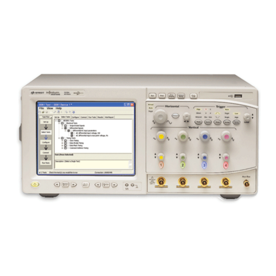
Preparing to Take Measurements Starting the DDR1 Compliance Test Application Ensure that the RAM reliability test software is running in the computer system where the Device Under Test (DUT) is attached. This software performs tests to all unused RAM in the system by producing a repetitive burst of read-write data signals to the DDR memory. - Page 28 Preparing to Take Measurements If DDR1 Test does not appear in the Automated Test Apps menu, the DDR1 Compliance Test NOTE Application has not been installed (see , “Installing the DDR1 Compliance Test Chapter 1 Application). Figure 1 shows the DDR1 Compliance Test Application main window. The task flow pane, and the tabs in the main pane, show the steps you take in running the automated tests: Description Set Up...
-
Page 29: Online Help Topics
Preparing to Take Measurements Online Help Topics For information on using the DDR1 Compliance Test Application, see its online help (which you can access by choosing Help>Contents... from the application’s main menu). The DDR1 Compliance Test Application’s online help describes: •... - Page 30 Preparing to Take Measurements DDR1 Compliance Testing Methods of Implementation...
-
Page 31: Single-Ended Signals Ac Input Parameters Tests
This section provides the Methods of Implementation (MOIs) for Single-Ended Signals AC Input tests using an Keysight 54850A, 8000, 80000 or 90000A series Infiniium oscilloscope, recommended InfiniiMax 116xA or 113xA probe amplifiers, E2677A differential solder-in probe head and the DDR1... -
Page 32: Probing For Single-Ended Signals Ac Input Parameters Tests
Single-Ended Signals AC Input Parameters Tests Probing for Single-Ended Signals AC Input Parameters Tests When performing the Single-Ended Signals AC Input Parameters tests, the DDR1 Compliance Test Application will prompt you to make the proper connections. The connection for the Single-Ended Signals AC Input Parameters tests may look similar to the following diagram. - Page 33 Single-Ended Signals AC Input Parameters Tests Select the Speed Grade options. For the Single-Ended Signals AC Input Parameters Tests, you can select any speed grade within the selection: DDR1-200, DDR1-266, DDR1-333, DDR1-400. Type in or select the Device Identifier as well as User Description from the drop-down list. Enter your comments in the Comments text box.
- Page 34 Single-Ended Signals AC Input Parameters Tests Follow the DDR1 Test Application’s task flow to set up the configuration options (see Table 2), run the tests and view the tests results. Table 2 Test Configuration Options Configuration Option Description Stop on error Enabling this error message will allow error message to prompt whenever criteria is not met.
-
Page 35: Slewr Test Method Of Implementation
Single-Ended Signals AC Input Parameters Tests Slew Test Method of Implementation Slew - Input Signal Minimum Slew Rate (Rising). The purpose of this test is to verify that the rising slew rate value of the test signal is greater than or equal to the conformance limit of the input SLEW value specified in the JEDEC Standard JESD79E. -
Page 36: Signals Of Interest
Single-Ended Signals AC Input Parameters Tests Signals of Interest Based on the test definition (Write cycle only): • Data Signal • Data Strobe Signal OR • Address Signal OR • Control Signal OR • Data Mask Control Signals Signals required to perform the test on the oscilloscope: •... -
Page 37: Test References
Single-Ended Signals AC Input Parameters Tests Calculate the delta TR. 10 Calculate Rising Slew. min V – - - - - - - - - - - - - - - - - - - - - - - - - - - - - - - - - - - IH ac gSlew ΔTR... -
Page 38: Slewf Test Method Of Implementation
Single-Ended Signals AC Input Parameters Tests Slew Test Method of Implementation Slew - Input Signal Minimum Slew Rate (Falling). The purpose of this test is to verify that the falling slew rate value of the test signal is greater than or equal to the conformance limit of the input SLEW value specified in the JEDEC Standard JESD79E. -
Page 39: Signals Of Interest
Single-Ended Signals AC Input Parameters Tests Signals of Interest Based on the test definition (Write cycle only): • Data Signal • Data Strobe Signal OR • Address Signal OR • Control Signal OR • Data Mask Control Signals Signals required to perform the test on the oscilloscope: •... -
Page 40: Test References
Single-Ended Signals AC Input Parameters Tests – - - - - - - - - - - - - - - - - - - - - - - - - - - - - - - - - - - - IL ac FallingSlew ΔTF... -
Page 41: Vih(Ac) Test Method Of Implementation
Single-Ended Signals AC Input Parameters Tests Test Method of Implementation IH(AC) Input Logic High Test can be divided into two sub tests - V test and V test. IH(AC) IH(DC) - Maximum AC Input Logic High. The purpose of this test is to verify that the maximum high IH(AC) level voltage value of the test signal within a valid sampling window is greater than the conformance lower limit of the V... -
Page 42: Test Definition Notes From The Specification
Single-Ended Signals AC Input Parameters Tests • Control Signal OR • Data Mask Control Signals Signals required to perform the test on the oscilloscope: • Data Signal (DQ as Pin Under Test Signal)* • Data Strobe Signal (DQS as Supporting Signal) •... -
Page 43: Test References
Single-Ended Signals AC Input Parameters Tests Test References See Table 7 - AC Operating Conditions and Table 8 - Low Power DDR SDRAM Electrical Characteristics, in the JEDEC Standard JESD79E. DDR1 Compliance Testing Methods of Implementation... -
Page 44: Vih(Dc) Test Method Of Implementation
Single-Ended Signals AC Input Parameters Tests Test Method of Implementation IH(DC) - Minimum DC Input Logic High. The purpose of this test is to verify that the minimum high IH(DC) level voltage value of the test signal within a valid sampling window is within the conformance limits of the V value specified in the JEDEC Standard JESD79E. -
Page 45: Test Definition Notes From The Specification
Single-Ended Signals AC Input Parameters Tests • Data Mask Control Signals Signals required to perform the test on the oscilloscope: • Data Signal (DQ as Pin Under Test Signal)* • Data Strobe Signal (DQS as Supporting Signal) • Clock Signal - CK is required to perform pre-test to verify the DUT speed against user’s speed grade selection * Pin Under Test signal can be either one of the signals under the test definition. -
Page 46: Test References
Single-Ended Signals AC Input Parameters Tests Test References See Table 6- Electrical Characteristics and DC Operating Conditions and Table 8 - Low Power DDR SDRAM Electrical Characteristics, in the JEDEC Standard JESD79E. DDR1 Compliance Testing Methods of Implementation... -
Page 47: Vil(Ac) Test Method Of Implementation
Single-Ended Signals AC Input Parameters Tests Test Method of Implementation IL(AC) AC Input Logic Low High Test can be divided into two sub tests: V test and V test. IL(AC) IL(DC) - Minimum AC Input Logic Low. The purpose of this test is to verify that the minimum low level IL(AC) voltage value of the test signal is lower than the conformance maximum limit of the V value... -
Page 48: Test Definition Notes From The Specification
Single-Ended Signals AC Input Parameters Tests • Data Mask Control Signals Signals required to perform the test on the oscilloscope: • Data Signal (DQ as Pin Under Test Signal)* • Data Strobe Signal (DQS as Supporting Signal) • Clock Signal - CK is required to perform pre-test to verify the DUT speed against user’s speed grade selection * Pin Under Test signal can be either one of the signals under the test definition. -
Page 49: Test References
Single-Ended Signals AC Input Parameters Tests Test References See Table 7 - AC Operating Conditions and Table 8 - Low Power DDR SDRAM Electrical Characteristics, in the JEDEC Standard JESD79E. DDR1 Compliance Testing Methods of Implementation... -
Page 50: Vil(Dc) Test Method Of Implementation
Single-Ended Signals AC Input Parameters Tests Test Method of Implementation IL(DC) - Maximum DC Input Logic Low. The purpose of this test is to verify that the maximum low IL(DC) level voltage value of the test signal within a valid sampling window is within the conformance limits of the V value specified in the JEDEC Standard JESD79E. -
Page 51: Test Definition Notes From The Specification
Single-Ended Signals AC Input Parameters Tests Signals required to perform the test on the oscilloscope: • Data Signal (DQ as Pin Under Test Signal)* • Data Strobe Signal (DQS as Supporting Signal) • Clock Signal - CK is required to perform pre-test to verify the DUT speed against user’s speed grade selection * Pin Under Test signal can be either one of the signals under the test definition. - Page 52 Single-Ended Signals AC Input Parameters Tests DDR1 Compliance Testing Methods of Implementation...
- Page 53 This section provides the Methods of Implementation (MOIs) for Single-Ended Signals AC Output tests using an Keysight 54850A, 8000, 80000 or 90000A series Infiniium oscilloscope, recommended InfiniiMax 116xA or 113xA probe amplifiers, E2677A differential solder-in probe head and the DDR1...
-
Page 54: Single-Ended Signals Ac Output Parameters Tests
Single-Ended Signals AC Output Parameters Tests Probing for Single-Ended Signals AC Output Parameters Tests When performing the Single-Ended Signals AC Output Parameters tests, the DDR1 Compliance Test Application will prompt you to make the proper connections. The connection for the Single-Ended Signals AC Output Parameters tests may look similar to the following diagram. - Page 55 Single-Ended Signals AC Output Parameters Tests In the DDR1 Test Application, click the Set Up tab. Select the Speed Grade options. For the Single-Ended Signals AC Input Parameters Tests, you can select any speed grade within the selection: DDR1-200, DDR1-266, DDR1-333, DDR1-400. Type in or select the Device Identifier as well as User Description from the drop-down list.
- Page 56 Single-Ended Signals AC Output Parameters Tests Table 17 Test Configuration Options Configuration Option Description Stop on error Enabling this option will allow error messages to prompt whenever the test criteria is not met. Disabling this option will allow the system to bypass all the error messages that could occur and proceed to the next test.
-
Page 57: Voh(Ac) Test Method Of Implementation
Single-Ended Signals AC Output Parameters Tests Test Method of Implementation OH(AC) - Maximum AC Output Logic High. This test is only applied to Low Power DDR SDRAM. The OH(AC) purpose of this test is to verify that the maximum high level voltage value of the test signal within a valid sampling window is greater than the conformance lower limit of the V value specified in OH(AC) -
Page 58: Test Definition Notes From The Specification
Single-Ended Signals AC Output Parameters Tests Signals required to perform the test on the oscilloscope: • Data Signal (DQ as Pin Under Test Signal)* • Data Strobe Signal (DQS as Supporting Signal) • Clock Signal - CK is required to perform pre-test to verify the DUT speed against user’s speed grade selection * Pin Under Test signal can be either one of the signals under the test definition. -
Page 59: Vol(Ac) Test Method Of Implementation
Single-Ended Signals AC Output Parameters Tests Test Method of Implementation OL(AC) - Minimum AC Output Logic Low. This test is only applied to Low Power DDR SDRAM. The OL(AC) purpose of this test is to verify that the minimum low level voltage value of the test signal is lower than the conformance maximum limit of the V value specified in the JEDEC Standard JESD79E. -
Page 60: Test Definition Notes From The Specification
Single-Ended Signals AC Output Parameters Tests • Data Strobe Signal (DQS as Supporting Signal) • Clock Signal - CK is required to perform pre-test to verify the DUT speed against user’s speed grade selection * Pin Under Test signal can be either one of the signals under the test definition. Test Definition Notes from the Specification Table 21 Low Power DDR SDRAM Electrical Characteristics... -
Page 61: Single-Ended Signals Overshoot/Undershoot Tests
AC Undershoot Test Method of Implementation / 68 This section provides the Methods of Implementation (MOIs) for Single-Ended Signals Overshoot/Undershoot tests using an Keysight 54850A, 8000, 80000 or 90000A series Infiniium oscilloscope, recommended InfiniiMax 116xA or 113xA probe amplifiers, E2677A differential solder-in... -
Page 62: Probing For Overshoot/Undershoot Tests
Single-Ended Signals Overshoot/Undershoot Tests Probing for Overshoot/Undershoot Tests When performing the Single-Ended Signals Overshoot/Undershoot tests, the DDR1 Compliance Test Application will prompt you to make the proper connections as shown in the following diagram. Refer to the Connection tab in DDR1 Compliance Test Application for the exact number of probe connections. - Page 63 Single-Ended Signals Overshoot/Undershoot Tests Connect the oscilloscope probes to any channels of the oscilloscope. In the DDR1 Test Application, click the Set Up tab. Select the Speed Grade options. For the Single-Ended Signals AC Input Parameters Tests, you can select any speed grade within the selection: DDR1-200, DDR1-266, DDR1-333, DDR1-400. Type in or select the Device Identifier as well as User Description from the drop-down list.
- Page 64 Single-Ended Signals Overshoot/Undershoot Tests Follow the DDR1 Test Application’s task flow to set up the configuration options (see Table 22), run the tests and view the tests results. Table 22 Test Configuration Options Configuration Option Description Stop on error Enabling this error message will allow error message to prompt whenever criteria is not met. Disabling this option will allow the system to bypass all the error messages that could occur and continue to the next test.
-
Page 65: Ac Overshoot Test Method Of Implementation
Single-Ended Signals Overshoot/Undershoot Tests AC Overshoot Test Method of Implementation The Overshoot test can be divided into two sub-tests: Overshoot amplitude and Overshoot area. The purpose of this test is to verify that the overshoot value of the test signal is lower than or equal to the conformance limit of the maximum peak amplitude allowed for overshoot as specified in the JEDEC Standard JESD79E. -
Page 66: Test Definition Notes From The Specification
Single-Ended Signals Overshoot/Undershoot Tests Signals required to perform the test on the oscilloscope: • Data Signal (DQ as Pin Under Test Signal)* • Data Strobe Signal (DQS as Supporting Signal) • Clock Signal - CK is required to perform pre-test to verify the DUT speed against user’s speed grade selection * Pin Under Test signal can be either one of the signals under the test definition. -
Page 67: Test References
Single-Ended Signals Overshoot/Undershoot Tests Get timestamp of maximum peak voltage on the waveform. Perform manual zoom waveform to maximum peak area. 10 Get the timestamp of voltage value for VDD(-1.8 V) level closest to the peak point value in order to calculate the maximum overshoot length duration. -
Page 68: Ac Undershoot Test Method Of Implementation
Single-Ended Signals Overshoot/Undershoot Tests AC Undershoot Test Method of Implementation The Undershoot Test can be divided into two sub-tests: Undershoot amplitude and Undershoot area. The purpose of this test is to verify that the undershoot value of the test signal is less than or equal to the conformance limit of the maximum peak amplitude allowed for undershoot as specified in the JEDEC Standard JESD79E. -
Page 69: Test Definition Notes From The Specification
Single-Ended Signals Overshoot/Undershoot Tests • Data Mask Control Signals Signals required to perform the test on the oscilloscope: • Data Signal (DQ as Pin Under Test Signal)* • Data Strobe Signal (DQS as Supporting Signal) • Clock Signal - CK is required to perform pre-test to verify the DUT speed against user’s speed grade selection * Pin Under Test signal can be either one of the signals under the test definition. -
Page 70: Test References
Single-Ended Signals Overshoot/Undershoot Tests Perform signal skew checking on the DQ-DQS to ensure that it can be triggered during the Read/Write separation later. Initialize the scope settings. Get timestamp of minimum peak voltage on the waveform. Perform manual zoom waveform to minimum peak area. 10 Get timestamp of voltage value for GND (0 V) level closest to the minimum peak point value in order to calculate the undershoot length duration. - Page 71 This section provides the Methods of Implementation (MOIs) for Differential Signals AC Input tests using an Keysight 54850A, 8000, 80000 or 90000A series Infiniium oscilloscope, recommended InfiniiMax 116xA or 113xA probe amplifiers, E2677A differential solder-in probe head and the DDR1...
-
Page 72: Differential Signals Ac Input Parameters Tests
Differential Signals AC Input Parameters Tests Probing for Differential Signals AC Input Parameters Tests When performing the Differential Signals AC Input Parameters tests, the DDR1 Compliance Test Application will prompt you to make the proper connections. The connection for the Differential Signals AC Input Parameters tests may look similar to the following diagram. - Page 73 Differential Signals AC Input Parameters Tests Connect the differential solder-in probe head to the PUTs on the DDR DIMM. Connect the oscilloscope probes to any channels of the oscilloscope. In the DDR1 Test Application, click the Set Up tab. Select the Speed Grade options. For the Single-Ended Signals AC Input Parameters Tests, you can select any speed grade within the selection: DDR1-200, DDR1-266, DDR1-333, DDR1-400.
- Page 74 Differential Signals AC Input Parameters Tests Follow the DDR1 Test Application’s task flow to set up the configuration options (see Table 27), run the tests and view the tests results. Table 27 Test Configuration Options Configuration Option Description Stop on error Enabling this error message will allow error message to prompt whenever criteria is not met.
-
Page 75: Vid(Ac), Ac Differential Input Vol Tage - Test Method Of Implementation
Differential Signals AC Input Parameters Tests , AC Differential Input Voltage - Test Method of Implementation ID(AC) The purpose of this test is to verify that the magnitude difference between the differential input signals pair is within the conformance limits of the V as specified in the JEDEC Standard ID(AC) JESD79E. -
Page 76: Signals Of Interest
Differential Signals AC Input Parameters Tests Figure 25 in Infiniium oscilloscope ID(AC) Signals of Interest Based on the test definition (Write cycle only): • Clock Signal Signals required to perform the test on the oscilloscope: • Clock Signal - CK is required to perform pre-test to verify the DUT speed against user’s speed grade selection DDR1 Compliance Testing Methods of Implementation... -
Page 77: Test Definition Notes From The Specification
Differential Signals AC Input Parameters Tests Test Definition Notes from the Specification Table 29 AC Operating Cond itions Parameter Symbol Units Notes Input Differential Voltage, CK and CK# inputs + 0.6 ID(AC) NOTE 9: V is the magnitude of the difference between the input level on CK and the input level on CK#. -
Page 78: Vix(Ac), Ac Differential Input Cross Point Vol Tage -Test Method Of Implementation
Differential Signals AC Input Parameters Tests , AC Differential Input Cross Point Voltage -Test Method of Implementation IX(AC) The purpose of this test is to verify the crossing point of the input differential test signals pair is within the conformance limits of the V as specified in the JEDEC Standard JESD79E. -
Page 79: Signals Of Interest
Differential Signals AC Input Parameters Tests Signals of Interest Based on the test definition (Write cycle only): • Clock Signal Signals required to perform the test on the oscilloscope: • Clock Signal - CK is required to perform pre-test to verify the DUT speed against user’s speed grade selection Test Definition Notes from the Specification Table 31... - Page 80 Differential Signals AC Input Parameters Tests DDR1 Compliance Testing Methods of Implementation...
-
Page 81: Data Strobe Timing (Dst) Tests
Read Postamble - Test Method of Implementation / 114 This section provides the Methods of Implementation (MOIs) for Data Strobe Timing tests using an Keysight 54850A, 8000, 80000 or 90000A series Infiniium oscilloscope, recommended InfiniiMax 116xA or 113xA probe amplifiers, E2677A differential solder-in probe head and the DDR1 Compliance Test Application. -
Page 82: Probing For Data Strobe Timing Tests
Data Strobe Timing (DST) Tests Probing for Data Strobe Timing Tests When performing the Data Strobe Timing tests, the DDR1 Compliance Test Application will prompt you to make the proper connections. The connection for Data Strobe Timing tests may look similar to the following diagram. - Page 83 Data Strobe Timing (DST) Tests Connect the differential solder-in probe head to the PUTs on the DDR DIMM. Connect the oscilloscope probes to any channels of the oscilloscope. In the DDR1 Test Application, click the Set Up tab. Select the Speed Grade options. For the Single-Ended Signals AC Input Parameters Tests, you can select any speed grade within the selection: DDR1-200, DDR1-266, DDR1-333, DDR1-400.
- Page 84 Data Strobe Timing (DST) Tests Follow the DDR1 Test application’s task flow to set up the configuration options (see Table 32), run the tests and view the tests results. Table 32 Test Configuration Options Configuration Option Description Stop on error Enabling this error message will allow error message to prompt whenever criteria is not met.
-
Page 85: Thz(Dq), Dq High Impedance Time From Ck/Ck# - Test Method Of Implementation
Data Strobe Timing (DST) Tests tHZ(DQ), DQ High Impedance Time From CK/CK# - Test Method of Implementation The purpose of this test is to verify that the time when the DQ is no longer driving (from high state OR low state to the high impedance stage), to the clock signal crossing, is within the conformance limits as specified in the JEDEC Standard JESD79E. -
Page 86: Pass Condition
Data Strobe Timing (DST) Tests NOTE 15: tHZ and tLZ transitions occurs in the same access time as valid data transitions. These parameters are referenced to a specific voltage level which specifies when the device output is no longer driving (tHZ), or begin driving (tLZ). Figure 30 shows a method to calculate the point when device is no longer driving (tHZ), or begins driving (tLZ) by measuring the signal at two different... -
Page 87: Thz(Dqs), Dqs High Impedance Time From Ck/Ck# - Test Method Of Implementation
Data Strobe Timing (DST) Tests tHZ(DQS), DQS High Impedance Time From CK/CK# - Test Method of Implementation The purpose of this test is to verify that the time when the DQS starts driving (from tristate to high state OR low state stage), to the clock signal crossing, is within the conformance limits as specified in the JEDEC Standard JESD79E. -
Page 88: Pass Condition
Data Strobe Timing (DST) Tests NOTE 15: tHZ and tLZ transitions occurs in the same access time as valid data transitions. These parameters are referenced to a specific voltage level which specifies when the device output is no longer driving (tHZ), or begin driving (tLZ). Figure 31 shows a method to calculate the point when device is no longer driving (tHZ), or begins driving (tLZ) by measuring the signal at two different... -
Page 89: Tlz(Dqs), Dqs Low-Impedance Time From Ck/Ck# - Test Method Of Implementation
Data Strobe Timing (DST) Tests tLZ(DQS), DQS Low-Impedance Time from CK/CK# - Test Method of Implementation The purpose of this test is to verify that the time when the DQS starts driving (from tristate to high/low state) to the clock signal crossing, is within the conformance limit as specified in the JEDEC Standard JESD79E. -
Page 90: Pass Condition
Data Strobe Timing (DST) Tests NOTE 15: tHZ and tLZ transitions occurs in the same access time as valid data transitions. These parameters are referenced to a specific voltage level which specifies when the device output is no longer driving (tHZ), or begin driving (tLZ). Figure 32 shows a method to calculate the point when device is no longer driving (tHZ), or begins driving (tLZ) by measuring the signal at two different... -
Page 91: Tlz(Dq), Dq Low-Impedance Time From Ck/Ck# - Test Method Of Implementation
Data Strobe Timing (DST) Tests tLZ(DQ), DQ Low-Impedance Time from CK/CK# - Test Method of Implementation The purpose of this test is to verify that the time when the DQ starts driving (from high impedance state to high/low state), to the clock signal crossing, is within the conformance limit as specified in the JEDEC Standard JESD79E. -
Page 92: Test Definition Notes From The Specification
Data Strobe Timing (DST) Tests • Data Signal (DQ as Pin Under Test Signal) • Data Strobe Signal (DQS as Supporting Signal) • Clock Signal (CK as Reference Signal) Optional signal required to separate the signals for the different Ranks: •... -
Page 93: Test References
Data Strobe Timing (DST) Tests 10 The Histogram Window is required to cover the DQ signal from the tristate to the moment it starts to drive high/low state. 11 Setup the threshold value and measurement point for the DQ signal based on the histogram result. -
Page 94: Implementation
Data Strobe Timing (DST) Tests tDQSQ, DQS-DQ Skew for DQS and Associated DQ Signals - Test Method of Implementation The purpose of this test is to verify that the time interval from the data strobe output (DQS rising and falling edge) access time to the associated data (DQ rising and falling) signal is within the conformance limit as specified in the JEDEC Standard JESD79E. -
Page 95: Test References
Data Strobe Timing (DST) Tests Perform signal skew checking on the DQ-DQS to ensure that it can be triggered during the Read/Write separation later. Chip Select (CS) option is only applicable if the user has selected “Yes” for the Verify Selected Rank Only option in the Configuration page. -
Page 96: Tqh, Dq/Dqs Output Hold Time From Dqs - Test Method Of Implementation
Data Strobe Timing (DST) Tests tQH, DQ/DQS Output Hold Time From DQS - Test Method of Implementation The purpose of this test is to verify that the time interval from the data output hold time (DQ rising and falling edge) from the DQS (rising and falling edge) is within the conformance limit as specified in the JEDEC Standard JESD79E. -
Page 97: Test References
Data Strobe Timing (DST) Tests Perform signal checking on all the signals in-use in the measurement to ensure that it can be triggered during the test. This includes Vp-p, Vmin, Vmax and Vmid of each signal. Perform signal skew checking on the DQ-DQS to ensure that it can be triggered during the Read/Write separation later. -
Page 98: Tdqss, Dqs Latching Transition To Associated Clock Edge - Test Method Of Implementation
Data Strobe Timing (DST) Tests tDQSS, DQS Latching Transition to Associated Clock Edge - Test Method of Implementation The purpose of this test is to verify that the time interval from the data strobe output (DQS falling edge) access time to the associated clock (crossing point) is within the conformance limit as specified in the JEDEC Standard JESD79E. -
Page 99: Test References
Data Strobe Timing (DST) Tests If you have selected the CS option, skip the next step and go to step 9. Search for the DQS preamble towards the left from the point where the Read cycle was previously captured. The For loops, TEdge and Delta Time are used to search the preamble. Once the preamble is located, call the “BinaryEdgeNormal”... -
Page 100: Tdqsh, Dqs Input High Pulse Width - Test Method Of Implementation
Data Strobe Timing (DST) Tests tDQSH, DQS Input High Pulse Width - Test Method of Implementation The purpose of this test is to verify that the width of the high level of the data strobe signal is within the conformance limit as specified in the JEDEC Standard JESD79E. Signals of Interest Based on the test definition (Read cycle only): •... -
Page 101: Test References
Data Strobe Timing (DST) Tests After obtaining the Edge number for the respective signal, begin the tDQSH measurement by using the Pwidth function to find any rising edge of the data strobe signal and measure the pwidth for every single bit in the captured data burst. Assign marker A for the rising edge of the clock signal while marker B for the falling edge of the clock signal. -
Page 102: Tdqsl, Dqs Input Low Pulse Width - Test Method Of Implementation
Data Strobe Timing (DST) Tests tDQSL, DQS Input Low Pulse Width - Test Method of Implementation The purpose of this test is to verify that the width of the low level of the clock signal is within the conformance limit as specified in the JEDEC Standard JESD79E. Signals of Interest Based on the test definition (Read cycle only): •... -
Page 103: Test References
Data Strobe Timing (DST) Tests Search for the DQS preamble towards the left from the point where the Read cycle was previously captured. The for loops, TEdge and Delta Time are used to search the preamble. Once the preamble is located, call the “BinaryEdgeNormal” function to obtain the Edge number. This Edge number will be used to locate the point of interest on the specific signal. -
Page 104: Tdss, Dqs Falling Edge To Ck Setup Time - Test Method Of Implementation
Data Strobe Timing (DST) Tests tDSS, DQS Falling Edge to CK Setup Time - Test Method of Implementation The purpose of this test is to verify that the time interval from the falling edge of the data strobe (DQS falling edge) output access time to the clock setup time, is within the conformance limit as specified in the JEDEC Standard JESD79E. -
Page 105: Test References
Data Strobe Timing (DST) Tests If you have selected the CS option, skip the next step and go to step 9. Search for the DQS preamble towards the left from the point where the Write cycle was previously captured. The For loops, TEdge and Delta Time are used to search the preamble. Once the preamble is located, call the “BinaryEdgeNormal”... -
Page 106: Tdsh, Dqs Falling Edge Hold Time From Ck - Test Method Of Implementation
Data Strobe Timing (DST) Tests tDSH, DQS Falling Edge Hold Time from CK - Test Method of Implementation The purpose of this test is to verify that the time interval from the falling edge of the data strobe output access time to the hold time of the clock, must be within the conformance limit as specified in the JEDEC Standard JESD79E. -
Page 107: Test References
Data Strobe Timing (DST) Tests If you have selected the CS option, skip the next step and go to step 9. Search for the DQS preamble towards the left from the point where the Write cycle was previously captured. The For loops, TEdge and Delta Time are used to search the preamble. Once the preamble is located, call the “BinaryEdgeNormal”... -
Page 108: Twpst, Write Postamble - Test Method Of Implementation
Data Strobe Timing (DST) Tests tWPST, Write Postamble - Test Method of Implementation The purpose of this test is to verify that the time when the DQS is no longer driving (from high/low state to high impedance) from the last DQS signal crossing (last bit of the write data burst) for the Write cycle, is within the conformance limit as specified in the JEDEC Standard JESD79E. -
Page 109: Test References
Data Strobe Timing (DST) Tests Chip Select (CS) option is only applicable if the user has selected “Yes” for the Verify Selected Rank Only option in the Configuration page. It uses the CS-DQS for signal separation. Else, by default, the DQS-DQ is used for signal separation. Use the InfiniiScan feature with the Setup time and Hold time to find and capture the Read cycle. -
Page 110: Twpre, Write Preamble - Test Method Of Implementation
Data Strobe Timing (DST) Tests tWPRE, Write Preamble - Test Method of Implementation The purpose of this test is to verify that the time when the DQS starts to drive low (preamble behavior) to the first DQS signal crossing for the Write cycle, is within the conformance limit as specified in the JEDEC Standard JESD79E. -
Page 111: Pass Condition
Data Strobe Timing (DST) Tests AC Characteristics Parameter Symbol DDR 400A (2.5-3-3) DDR 400B (3-3-3) DDR 400C (3-4-4) Units Write preamble tWPRE max (0.25*tCK, 1.5 ns) max (0.25*tCK, 1.5 ns) (0.25*tCK, 1.5 ns) PASS Condition The measured time interval of the point where the DQS starts to transit from tristate (high impedance state to low state) to the DQS signal crossing point for the Write cycle, should be within the specification limit. -
Page 112: Trpre, Read Preamble - Test Method Of Implementation
Data Strobe Timing (DST) Tests tRPRE, Read Preamble - Test Method of Implementation The purpose of this test is to verify that the time when the DQS start driving low (*preamble behavior) to the first DQS signal crossing for the Read cycle must be within the conformance limit as specified in the JEDEC Standard JESD79E. -
Page 113: Measurement Algorithm
Data Strobe Timing (DST) Tests Measurement Algorithm Obtain the parameters and settings from the Configuration page. Pre-condition the scope settings. Verify the actual DUT speed against the user speed selection at the Setup page. Perform signal checking on all the signals in-use in the measurement to ensure that it can be triggered during the test. -
Page 114: Trpst, Read Postamble - Test Method Of Implementation
Data Strobe Timing (DST) Tests tRPST, Read Postamble - Test Method of Implementation The purpose of this test is to verify that the time when the DQS is no longer driving (from high/low state to high-impedance) to the last DQS signal crossing (last bit of the data burst) for the Read cycle is within the conformance limit as specified in the JEDEC Standard JESD79E. -
Page 115: Test References
Data Strobe Timing (DST) Tests Chip Select (CS) option is only applicable if the user has selected “Yes” for the Verify Selected Rank Only option in the Configuration page. It uses the CS-DQS for signal separation. Else, by default, the DQS-DQ is used for signal separation. Use the InfiniiScan feature with the Setup time and Hold time to find and capture the Read cycle. - Page 116 Data Strobe Timing (DST) Tests DDR1 Compliance Testing Methods of Implementation...
-
Page 117: Clock Timing (Ct) Tests
Average Low Pulse Width - tCL(avg) - Test Method of Implementation / 131 This section provides the Methods of Implementation (MOIs) for Clock Timing tests using an Keysight 54850A, 8000, 80000 or 90000A series Infiniium oscilloscope, recommended InfiniiMax 116xA or 113xA probe amplifiers, E2677A differential solder-in probe head and the DDR1 Compliance Test Application. -
Page 118: Probing For Clock Timing Tests
Clock Timing (CT) Tests Probing for Clock Timing Tests When performing the Clock Timing tests, the DDR1 Compliance Test Application will prompt you to make the proper connections. The connection for Clock Timing tests may look similar to the following diagram. - Page 119 Clock Timing (CT) Tests Connect the differential solder-in probe head to the PUTs on the DDR DIMM. Connect the oscilloscope probes to any channels of the oscilloscope. In the DDR1 Test Application, click the Set Up tab. Select the Speed Grade options. For the Single-Ended Signals AC Input Parameters Tests, you can select any speed grade within the selection: DDR1-200, DDR1-266, DDR1-333, DDR1-400.
- Page 120 Clock Timing (CT) Tests Follow the DDR1 Test Application’s task flow to set up the configuration options (see Table 48), run the tests and view the tests results. Table 48 Test Configuration Options Configuration Option Description Stop on error Enabling this error message will allow error message to prompt whenever criteria is not met.
-
Page 121: Tac, Dq Output Access Time From Ck/Ck# - Test Method Of Implementation
Clock Timing (CT) Tests tAC, DQ Output Access Time from CK/CK# - Test Method of Implementation The purpose of this test is to verify that the time interval from data output (DQ Rising and Falling Edge) access time to the nearest rising or falling edge of the clock must be within the conformance limit as specified in the JEDEC Standard JESD79E. -
Page 122: Pass Condition
Clock Timing (CT) Tests AC Characteristics - Parameter Symbol DDR 400A (2.5-3-3) DDR 400B (3-3-3) DDR 400C (3-4-4) Units Notes DQ output access time from CK/CK -0.7 +0.7 -0.7 +0.7 -0.7 +0.7 Table 50 AC Timing Variations for DDR 333, DDR 266 & DDR 200 Devices Parameter DDR 333B DDR 266A... -
Page 123: Test References
Clock Timing (CT) Tests Test References See Table 11 - Electrical Characteristics and AC Timing and Table 12 - AC Timing Variations For DDR 333, DDR 266 and DDR 200 Devices, in the JEDEC Standard JESD79E. DDR1 Compliance Testing Methods of Implementation... -
Page 124: Tdqsck, Dqs Output Access Time From Ck/Ck #- Test Method Of Implementation
Clock Timing (CT) Tests tDQSCK, DQS Output Access Time from CK/CK #- Test Method of Implementation The purpose of this test is to verify that the time interval from the data strobe output (DQS rising and falling edge) access time to the nearest rising or falling edge of the clock is within the conformance limit as specified in the JEDEC Standard JESD79E. -
Page 125: Signals Of Interest
Clock Timing (CT) Tests Figure 40 tDQSCK in Infiniium oscilloscope Signals of Interest Based on the test definition (Read cycle only): • Data Strobe Signal (DQS as Pin Under Test Signal) • Clock Signal (CK as Reference Signal) Signals required to perform the test on the oscilloscope: •... -
Page 126: Test Definition Notes From The Specification
Clock Timing (CT) Tests Test Definition Notes from the Specification Table 51 Electrical Characteristics and AC Timing AC Characteristics - Parameter Symbol DDR 333 DDR 266 DDR 200 Units Notes DQS output access time from CK/CK tDQSCK -0.60 +0.60 -0.75 +0.75 -0.8 +0.8... -
Page 127: Test References
Clock Timing (CT) Tests 14 Once all bits are validated, assign marker A for the clock signal while marker B for the data signal, for the worst case bit. 15 Measure delta of marker A and marker B and this will be the test result. 16 Compare the test result against the compliance test limit. -
Page 128: Average Clock Period - Tck(Avg) - Test Method Of Implementation
Clock Timing (CT) Tests Average Clock Period - tCK(avg) - Test Method of Implementation This test is applicable to the Rising Edge Measurement as well as the Falling Edge Measurement. tCK(avg) is average clock period within 200 consecutive cycle window. The tCK(avg) Rising Edge Measurement measures the period from the rising edge of a cycle to the next rising edge within the waveform window. -
Page 129: Measurement Algorithm
Clock Timing (CT) Tests Measurement Algorithm Example input test signal: Frequency: 1 KHz, Number of cycles acquired: 202. This measurement measures a sliding “window” of 200 cycles. Calculate the average period value for periods 1-200, 2-201 and 3-202. Check the results for the smallest and largest values (worst case values). Compare the test results against the compliance test limits. -
Page 130: Average High Pulse Wid Th - Tch(Avg) - Test Method Of Implementation
Clock Timing (CT) Tests Average High Pulse Width - tCH(avg) - Test Method of Implementation The purpose of this test is to measure the average duty cycle of all the positive pulse widths within a window of 200 consecutive cycles. Signals of Interest Based on the test definition: •... -
Page 131: Average Low Pulse Wid Th - Tcl(Avg) - Test Method Of Implementation
Clock Timing (CT) Tests Average Low Pulse Width - tCL(avg) - Test Method of Implementation The purpose of this test is to measure the average duty cycle of all the negative pulse widths within a window of 200 consecutive cycles. Signals of Interest Based on the test definition: •... - Page 132 Clock Timing (CT) Tests DDR1 Compliance Testing Methods of Implementation...
- Page 133 DQ and DM Input Hold Time - Test Method of Implementation / 139 This section provides the Methods of Implementation (MOIs) for Data Mask Timing tests using an Keysight 54850A, 8000, 80000 or 90000A series Infiniium oscilloscope, recommended InfiniiMax 116xA or 113xA probe amplifiers, E2677A differential solder-in probe head and the DDR1 Compliance Test Application.
-
Page 134: Probing For Data Mask Timing Tests
Data Mask Timing (DMT) Tests Probing for Data Mask Timing Tests When performing the Data Mask Timing tests, the DDR1 Compliance Test Application will prompt you to make the proper connections. The connection for Data Mask Timing tests may look similar to the following diagrams. - Page 135 Data Mask Timing (DMT) Tests Connect the differential solder-in probe head to the PUTs on the DDR DIMM. Connect the oscilloscope probes to any channels of the oscilloscope. In the DDR1 Test Application, click the Set Up tab. Select the Speed Grade options. For the Single-Ended Signals AC Input Parameters Tests, you can select any speed grade within the selection: DDR1-200, DDR1-266, DDR1-333, DDR1-400.
- Page 136 Data Mask Timing (DMT) Tests Follow the DDR1 Test Application’s task flow to set up the configuration options (see Table 57), run the tests and view the tests results. Table 57 Test Configuration Options Configuration Option Description Stop on error Enabling this error message will allow error message to prompt whenever criteria is not met.
-
Page 137: Tds(Base), Dq And Dm Input Setup Time - Test Method Of Implementation
Data Mask Timing (DMT) Tests tDS(base), DQ and DM Input Setup Time - Test Method of Implementation The purpose of this test is to verify that the time interval from the data or data mask (DQ/DM rising/falling Edge) setup time to the associated DQS crossing edge is within the conformance limits as specified in the JEDEC Standard JESD79E. -
Page 138: Measurement Algorithm
Data Mask Timing (DMT) Tests Measurement Algorithm Obtain the parameters and settings from the Configuration page. Pre-condition the scope settings. Verify the actual DUT speed against the user speed selection at the Setup page. Perform signal checking on all the signals in-use in the measurement to ensure that it can be triggered during the test. -
Page 139: Tdh(Base), Dq And Dm Input Hold Time - Test Method Of Implementation
Data Mask Timing (DMT) Tests tDH(base), DQ and DM Input Hold Time - Test Method of Implementation The purpose of this test is to verify that the time interval from the data or data mask (DQ/DM rising/falling edge) setup time to the associated DQS crossing edge is within the conformance limits as specified in the JEDEC Standard JESD79E. -
Page 140: Pass Condition
Data Mask Timing (DMT) Tests PASS Condition The measured time interval between the data or data mask (DQ/DM) hold time to the respective DQS crossing point should be within the specification limit. Measurement Algorithm Obtain the parameters and settings from the Configuration page. Pre-condition the scope settings. -
Page 141: Command And Address Timing (Cat) Tests
This section provides the Methods of Implementation (MOIs) for Command and Address Timing tests using an Keysight 54850A, 8000, 80000 or 90000A series Infiniium oscilloscope, recommended InfiniiMax 116xA or 113xA probe amplifiers, E2677A differential solder-in probe head and the DDR1 Compliance Test Application. -
Page 142: Probing For Command And Address Timing Tests
Command and Address Timing (CAT) Tests Probing for Command and Address Timing Tests When performing the Command and Address Timing tests, the DDR1 Compliance Test Application will prompt you to make the proper connections. The connection for Command and Address Timing tests may look similar to the following diagrams. -
Page 143: Test Procedure
Command and Address Timing (CAT) Tests Test Procedure Start the automated test application as described in “Starting the DDR1 Compliance Test Application" on page 27. Ensure that the RAM reliability test software is running on the computer system where the DDR Device Under Test (DUT) is attached. - Page 144 Command and Address Timing (CAT) Tests Follow the DDR1 Test application’s task flow to set up the configuration options (see Table 60), run the tests and view the tests results. Table 60 Test Configuration Options Configuration Option Description Stop on error Enabling this error message will allow error message to prompt whenever criteria is not met.
-
Page 145: Tis(Base) - Address And Control Input Setup Time - Test Method Of Implementation
Command and Address Timing (CAT) Tests tIS(base) - Address and Control Input Setup Time - Test Method of Implementation The purpose of this test is to verify that the time interval from the address or control (rising or falling edge) setup time to the associated clock crossing edge is within the conformance limits of the V ID(ac) as specified in the JEDEC Standard JESD79E. -
Page 146: Measurement Algorithm
Command and Address Timing (CAT) Tests Measurement Algorithm Obtain the parameters and settings from the Configuration page. Pre-condition the scope settings. Verify the actual DUT speed against the user speed selection at the Setup page. Perform signal checking on all the signals in-use in the measurement to ensure that it can be triggered during the test. -
Page 147: Tih(Base) - Address And Control Input Hold Time - Test Method Of Implementation
Command and Address Timing (CAT) Tests tIH(base) - Address and Control Input Hold Time - Test Method of Implementation The purpose of this test is to verify that the time interval from the address or control (rising or falling edge) hold time to the associated clock crossing edge is within the conformance limits as specified in the JEDEC Standard JESD79E. -
Page 148: Measurement Algorithm
Command and Address Timing (CAT) Tests Measurement Algorithm Obtain the parameters and settings from the Configuration page. Pre-condition the scope settings. Verify the actual DUT speed against the user speed selection at the Setup page. Perform signal checking on all the signals in-use in the measurement to ensure that it can be triggered during the test. - Page 149 Half Period Jitter - tJIT(duty) - Test Method of Implementation / 157 This section provides the Methods of Implementation (MOIs) for Rising Edge and Pulse Measurements Clock tests using an Keysight 54850A, 8000, 80000 or 90000A series Infiniium oscilloscope, recommended InfiniiMax 116xA or 113xA probe amplifiers, E2677A differential solder-in...
-
Page 150: Advanced Debug Mode Clock Tests
Advanced Debug Mode Clock Tests Probing for Clock Tests When performing the Advanced Debug Mode Clock tests, the DDR1 Compliance Test Application will prompt you to make the proper connections. The connections for Rising Edge and Pulse Measurement Clock tests may look similar to the following diagram. Refer to the Connection tab in DDR1 Electrical Performance Compliance application for the exact number of probe connections. - Page 151 Advanced Debug Mode Clock Tests In the DDR1 test application, click the Set Up tab. Select Advanced Debug as the Test Mode option. Figure 46 Selecting Advanced Debug Mode Advanced Debug also allows you to type in the data rate of the DUT signal. Type in or select the Device Identifier as well as the User Description from the drop-down list.
- Page 152 Advanced Debug Mode Clock Tests Figure 47 Selecting Advanced Debug Clock Tests DDR1 Compliance Testing Methods of Implementation...
- Page 153 Advanced Debug Mode Clock Tests 10 Follow the DDR1 Test application’s task flow to set up the configuration options (see Table 63), run the tests and view the tests results. Table 63 Test Configuration Options Configuration Option Description Stop on error Enabling this error message will allow error message to prompt whenever criteria is not met.
-
Page 154: Clock Period Jitter - Tjit(Per) - Test Method Of Implementation
Advanced Debug Mode Clock Tests Clock Period Jitter - tJIT(per) - Test Method of Implementation This test is applicable to the Rising Edge Measurement and Falling Edge Measurement. The purpose of this test is to measure the difference between a measured clock period and the average clock period across multiple cycles of the clock. -
Page 155: Cycle To Cycle Period Jitter - Tjit(Cc) - Test Method Of Implementation
Advanced Debug Mode Clock Tests Cycle to Cycle Period Jitter - tJIT(cc) - Test Method of Implementation This test is applicable to the Rising Edge Measurement as well as Falling Edge Measurement. The purpose of this test is to measure the difference in the clock period between two consecutive clock cycles. -
Page 156: Cumulative Error - Terr(N Per) - Test Method Of Implementation
Advanced Debug Mode Clock Tests Cumulative Error - tERR(n per) - Test Method of Implementation This Cumulative Error (across “n” cycles) test is applicable to the Rising Edge Measurement as well as the Falling Edge Measurement. The purpose of this test is to measure the difference between a measured clock period and the average clock period across multiple cycles of the clock. -
Page 157: Half Period Jitter - Tjit(Duty) - Test Method Of Implementation
Advanced Debug Mode Clock Tests Half Period Jitter - tJIT(duty) - Test Method of Implementation The Half Period Jitter tJIT(duty) can be divided into tJIT(CH) Jitter Average High and tJIT(LH) Jitter Average Low. The tJIT(CH) Jitter Average High Measurement measures between a positive pulse width of a cycle in the waveform, and the average positive pulse width of all cycles in a 200 consecutive cycle window. - Page 158 Advanced Debug Mode Clock Tests DDR1 Compliance Testing Methods of Implementation...
-
Page 159: Advanced Debug Mode High-Low State Ringing Tests
Low State Ringing Tests Method of Implementation / 166 This section provides the Methods of Implementation (MOIs) for Advanced Debug Mode High-Low State Ringing tests using an Keysight 54850A, 8000, 80000 or 90000A series Infiniium oscilloscope, recommended InfiniiMax 116xA or 113xA probe amplifiers, E2677A differential solder-in probe head... -
Page 160: Probing For Advanced Debug Mode High-Low State Ringing Tests
Advanced Debug Mode High-Low State Ringing Tests Probing for Advanced Debug Mode High-Low State Ringing Tests When performing the intra-pair skew tests, the DDR1 Compliance Test Application will prompt you to make the proper connections as shown in Figure Infiniium Oscilloscope DDR DIMM InfiniiMax solder-in probes Figure 48... - Page 161 Advanced Debug Mode High-Low State Ringing Tests Figure 49 Selecting Advanced Debug Mode Advanced Debug also allows you to type in the data rate of the DUT signal. Type in or select the Device Identifier as well as the User Description from the drop-down list. Enter your comments in the Comments text box.
- Page 162 Advanced Debug Mode High-Low State Ringing Tests Figure 50 Selecting Advanced Debug High-Low State Ringing Tests 10 Follow the DDR1 Test application’s task flow to set up the configuration options (see Table 64), run the tests and view the tests results. DDR1 Compliance Testing Methods of Implementation...
- Page 163 Advanced Debug Mode High-Low State Ringing Tests Table 64 Test Configuration Options Configuration Option Description Stop on error Enabling this error message will allow error message to prompt whenever criteria is not met. Disabling this option will allow the system to bypass all the error messages that could occur and continue to the next test.
-
Page 164: High State Ringing Tests Method Of Implementation
Advanced Debug Mode High-Low State Ringing Tests High State Ringing Tests Method of Implementation The Advanced Debug Mode Ringing test can be divided into two sub-tests. One of them is the High State Ringing test. There is no available specification for this test in the JEDEC Standard JESD79E specifications. -
Page 165: Measurement Algorithm
Advanced Debug Mode High-Low State Ringing Tests Measurement Algorithm Acquire initial signal data and then perform signal conditioning to maximize the screen resolution - vertical scale adjustment. Setup the InfiniiScan to activate the RUNT mode. Acquire test data with the InfiniiScan RUNT activated. Display Markers to show the RUNT Upper Level and RUNT Lower Level. -
Page 166: Low State Ringing Tests Method Of Implementation
Advanced Debug Mode High-Low State Ringing Tests Low State Ringing Tests Method of Implementation Just as the High State Ringing test, there is no available specification in the JEDEC Standard JESD79E specifications for the Low State Ringing tests. The ringing debug test is definable by the customers to capture the glitch of interest for the logic low state section in a test signal for evaluation purposes. -
Page 167: Measurement Algorithm
Advanced Debug Mode High-Low State Ringing Tests Measurement Algorithm Acquire initial signal data and then perform signal conditioning to maximize the screen resolution - vertical scale adjustment. Setup the InfiniiScan to activate the RUNT mode. Acquire test data with the InfiniiScan RUNT activated. Display Markers to show the RUNT Upper Level and RUNT Lower Level. - Page 168 Advanced Debug Mode High-Low State Ringing Tests DDR1 Compliance Testing Methods of Implementation...
-
Page 169: Calibrating The Infiniium Oscilloscope And Probe
Oscilloscope and Probe Required Equipment for Oscilloscope Calibration / 170 Internal Calibration / 171 Required Equipment for Probe Calibration / 174 Probe Calibration / 175 Verifying the Probe Calibration / 182 This section describes the Keysight Infiniium digital storage oscilloscope calibration procedures. -
Page 170: Required Equipment For Oscilloscope Calibration
• Mouse, qty = 1, (provided with the Keysight Infiniium oscilloscope). • Precision 3.5 mm BNC to SMA male adapter, Keysight p/n 54855-67604, qty = 2 (provided with the Keysight Infiniium oscilloscope). • Calibration cable (provided with the 54850A, 8000, 80000 or 90000A series Infiniium Ω... -
Page 171: Internal Calibration
Calibrating the Infiniium Oscilloscope and Probe Internal Calibration This will perform an internal diagnostic and calibration cycle for the oscilloscope. For the Keysight oscilloscope, this is referred to as Calibration. This Calibration will take about 20 minutes. Perform the following steps: Set up the oscilloscope with the following steps: a Connect the keyboard, mouse, and power cord to the rear of the oscilloscope. - Page 172 Calibrating the Infiniium Oscilloscope and Probe Referring to Figure 55 below, perform the following steps to start the calibration: b Uncheck the Cal Memory Protect checkbox. c Click the Start button to begin the calibration. Figure 55 Oscilloscope Calibration Window DDR1 Compliance Testing Methods of Implementation...
- Page 173 Calibrating the Infiniium Oscilloscope and Probe d During the calibration of channel 1, if you are prompted to perform a Time Scale Calibration, as shown in Figure 56 below. Figure 56 Time Scale Calibration Dialog box e Click on the Std+Dflt button to continue the calibration, using the Factory default calibration factors.
-
Page 174: Required Equipment For Probe Calibration
Calibrating the Infiniium Oscilloscope and Probe Required Equipment for Probe Calibration Before performing DDR1 tests you should calibrate the probes. Calibration of the solder-in probe heads consist of a vertical calibration and a skew calibration. The vertical calibration should be performed before the skew calibration. -
Page 175: Probe Calibration
Calibrating the Infiniium Oscilloscope and Probe Probe Calibration Connecting the Probe for Calibration For the following procedure, refer to Figure 57 below. Connect BNC (male) to SMA (male) adaptor to the deskew fixture on the connector closest to the yellow pincher. Ω... - Page 176 Calibrating the Infiniium Oscilloscope and Probe BNC to SMA Connector Pincher Deskew Fixture 50 W SMA Terminator Figure 57 Solder-in Probe Head Calibration Connection Example DDR1 Compliance Testing Methods of Implementation...
-
Page 177: Verifying The Connection
Calibrating the Infiniium Oscilloscope and Probe Verifying the Connection On the Infiniium oscilloscope, press the autoscale button on the front panel. Set the volts per division to 100 mV/div. Set the horizontal scale to 1.00 ns/div. Set the horizontal position to approximately 3 ns. You should see a waveform similar to that in Figure 58 below. - Page 178 Calibrating the Infiniium Oscilloscope and Probe If you see a waveform similar to that of Figure 59 below, then you have a bad connection and should check all of your probe connections. Figure 59 Bad Connection Waveform Example DDR1 Compliance Testing Methods of Implementation...
-
Page 179: Running The Probe Calibration And Deskew
Calibrating the Infiniium Oscilloscope and Probe Running the Probe Calibration and Deskew On the Infiniium oscilloscope in the Setup menu, select the channel connected to the probe, as shown in Figure Figure 60 Channel Setup Window. DDR1 Compliance Testing Methods of Implementation... - Page 180 Calibrating the Infiniium Oscilloscope and Probe In the Channel Setup dialog box, select the Probes... button, as shown in Figure Figure 61 Channel Dialog Box In the Probe Setup dialog box, select the Calibrate Probe... button. Figure 62 Probe Setup Window. DDR1 Compliance Testing Methods of Implementation...
- Page 181 Calibrating the Infiniium Oscilloscope and Probe In the Probe Calibration dialog box, select the Calibrated Atten/Offset radio button. Select the Start Atten/Offset Calibration... button and follow the on-screen instructions for the vertical calibration procedure. Figure 63 Probe Calibration Window. Once the vertical calibration has successfully completed, select the Calibrated Skew... button. Select the Start Skew Calibration...
-
Page 182: Verifying The Probe Calibration
BNC (male) to SMA (male) adaptor • SMA (male) to BNC (female) adaptor • BNC (male) to BNC (male) 12 inch cable such as the Keysight 8120-1838 • Keysight 54855-61620 calibration cable (Infiniium oscilloscopes with bandwidths of 6 GHz and greater only) •... - Page 183 Calibrating the Infiniium Oscilloscope and Probe BNC to SMA Connector Pincher Deskew Fixture 50 W SMA Terminator Figure 64 Probe Calibration Verification Connection Example DDR1 Compliance Testing Methods of Implementation...
- Page 184 Calibrating the Infiniium Oscilloscope and Probe 17 Select the Start Skew Calibration... button and follow the on-screen instructions. 18 Set the vertical scale for the displayed channels to 100 mV/div. 19 Set the horizontal range to 1.00 ns/div. 20 Set the horizontal position to approximately 3 ns. 21 Change the vertical position knobs of both channels until the waveforms overlap each other.
- Page 185 Figure 66 1134A InfiniiMax Probe Amplifier Keysight recommends 116xA or 113xA probe amplifiers, which range from 3.5 GHz to 12 GHz. Keysight also recommends the E2677A differential solder-in probe head. Other probe head options include N5381A InfiniiMax II 12 GHz differential solder-in probe head, N5382A InfiniiMax II 12 GHz differential browser, E2675A InfiniiMax differential browser probe head, N5425A InfiniiMax ZIF probe head and N5426A ZIF Tips.
- Page 186 InfiniiMax Probing Table 65 Probe Head Characteristics (with 1134A probe amplifier) Probe Head Model Differential Measurement Single-Ended Measurement Number (BW, input C, input R) (BW, input C, input R) Differential Solder-in E2677A 7 GHz, 0.27 pF, 50 kOhm 7 GHz, 0.44 pF, 25 kOhm Used with 1168A or 1169A probe amplifier, the E2677A differential solder-in probe head provides 10 GHz and 12 GHz bandwidth respectively.
- Page 187 Keysight U7233A/U7233B DDR1 Compliance Test Application Compliance Testing Methods of Implementation 15 Common Error Messages Required Triggering Condition Not Met / 188 Software License Error / 190 Frequency Out of Range Error / 191 Missing Signal Error / 192 Missing Signal Error / 192...
-
Page 188: Required Triggering Condition Not Met
Common Error Messages Required Triggering Condition Not Met The following error message will appear when a time-out occurs. This error message indicates that the required triggering condition is not met. This is followed by test cancellation and aborting message. All pending tests will be cancelled. Figure 68 Required Trigger Condition Not Met Error Message Figure 69... - Page 189 Common Error Messages • The probes are properly calibrated and skewed. Ensure that correct probes are used and they are properly calibrated, so that it reflects the actual signal and is not over or under amplified. Similarly, ensure that the channels are properly soldered on the DDR1 module and ensure that the signals are not over skewed.
-
Page 190: Software License Error
Common Error Messages Software License Error When you load the N5413A DDR1 Compliance Test Application, it checks for the required software licenses. When one of the optional licenses is not detected, the application will limit the available test options and the Set Up tab will look similar to following screenshot. Figure 70 Software License Error Ensure you have installed all required licenses before running the N5413A DDR1 Compliance Test... -
Page 191: Frequency Out Of Range Error
Common Error Messages Frequency Out of Range Error You are allowed to type in the DUT data rate for the Advanced Debug Mode tests. However, if you enter an incorrect data strobe test signal frequency, the following error dialog box appears. For example, if the selected DDR1 speed grade option is DDR1-400, the expected frequency of the data strobe signal, DQS is 200MH (half of the data transfer rate). -
Page 192: Missing Signal Error
Common Error Messages Missing Signal Error This error occurs when the required signals are either not selected in the “Channel Setting” configuration or not connected to the oscilloscope. Ensure that correct channel is selected based on the signal that is physically present at the oscilloscope channel. Figure 72 Missing Signal Error Message DDR1 Compliance Testing Methods of Implementation... -
Page 193: Invalid Pre/Postamble Signal Error
Common Error Messages Invalid Pre/PostAmble Signal Error This error occurs during the multiple trial run if there is no significant voltage level transits when the driver is turned on or off during the preamble or postamble. You should verify the signals especially the DQS and DQ if they provide a valid preamble or postamble signal. - Page 194 Common Error Messages DDR1 Compliance Testing Methods of Implementation...
- Page 195 Index DQS Latching Transition to Associated Clock Edge, DQS Low-Impedance Time from AC Differential Input Cross Point precision 3.5 mm BNC to SMA male CK/CK#, Voltage, adapter, DQS Output Access Time from CK/CK AC Differential Input Voltage, probe calibration, Address and Control Input Hold Probing for Advanced Debug Mode DQS-DQ Skew for DQS and Associated Time,...
- Page 196 Index tDQSH, tDQSL, tDQSQ, tDQSS, tDS(base), tDSH, tDSS, tERR(n per), tHZ(DQ), 85, tHZ(DQS), tIH(base), tIS(base), tJIT(cc), tJIT(duty), tJIT(per), tLZ(DQ), tLZ(DQS), tQH, tRPRE, tRPST, tWPRE, tWPST, VID(AC), VIH(ac), VIH(dc), VIL(ac), VIL(dc), VIX(ac), VOH(AC), VOH(DC), VOL(AC), Write Postamble, Write Preamble, ZIF probe, ZIF tips, DDR1 Compliance Testing Methods of Implementation...
Need help?
Do you have a question about the U7233A and is the answer not in the manual?
Questions and answers