Table of Contents
Advertisement
Quick Links
Advertisement
Table of Contents

Related Manuals for Keysight PD1500A


Summary of Contents for Keysight PD1500A
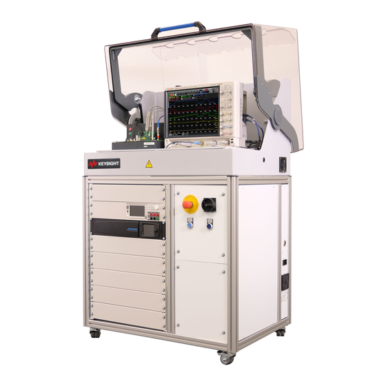
- Page 1 Keysight PD1500A Si/SiC Test Fixture and Modules Provides detailed information to install and use the Dou- ble-Pulse Test Modules for testing Si/SiC devices in the DPT Test Fixture. Used in the PD1500A Dynamic Power Device Analyzer/Double-Pulse Tester. Installation and Use Guide...
- Page 3 Warranty © Keysight Technologies, Inc. 2020 No part of this manual may be repro- To contact Keysight for sales and techni- THE MATERIAL CONTAINED IN THIS duced in any form or by any means cal support, refer to the support links on DOCUMENT IS PROVIDED “AS IS,”...
- Page 4 Return the product to a precautions or with specific warnings containers of such liquids. Keysight Sales and Service Office to or operating instructions in the product ensure that safety features are main- manuals violates safety standards of Cleaning tained.
- Page 5 Indicates that antistatic To return unwanted products, contact precautions should be your local Keysight office for more taken. information. DANGER: High Voltage Hot Surface; DO NOT...
- Page 6 The use of any other accessory is not recommended or supported. Intended Use of Equipment The Keysight Double-Pulse Test Rack and Safety Enclosure and Test Fixtures, along with the recommended accessories, are intended to be used for the PD1500A Dynamic Power Device...
- Page 7 Failure to comply with these precautions or with specific warnings elsewhere in this manual may impair the protections provided by the system. In addition, it violates safety standards of design, manufacture, and intended use of the system. Keysight Technologies assumes no liability for customer’s failure to comply with these requirements.
- Page 8 • Instruments, probes or cables that appear damaged or defective should be made inoperative and secured against unintended operation until they can be repaired by qualified service personnel. Return the product to a Keysight Technologies sales or service office for service and repair to ensure that safety features are maintained.
- Page 9 Periodically inspect the probe wires to check for any cracks, damage, or defective leads. Do Not Operate With Visible or Suspected Damage. If you suspect there is damage, have it inspected by a Keysight authorized service personnel. Capacitors inside the instrument may retain a charge even if the instrument is disconnected from its source of supply.
- Page 10 Probe cables are a sensitive part of the probe. Be careful not to damage it through excessive bending or pulling. Avoid any mechanical shocks to this product in order to guarantee accurate performance and protection. Keysight DPT Test Fixture User Guide...
- Page 11 Fixture and System Control Rack and Safety Modules Software Enclosure Rack and Safety Test Fixture & Modules PD1500A Control Enclosure Operation Guide Installation and Use Guide Software Guide Keysight DPT Test Fixture Installation and Use Guide...
- Page 12 Keysight DPT Test Fixture Installation and Use Guide...
-
Page 13: Table Of Contents
Static-safe Handling Procedures ....... . . 16 PD1000A Test Fixture for the PD1500A Double-Pulse Test System ..17 Connections on Back of Test Fixture . - Page 14 Using a Small-tip Soldering Iron ....... . . 76 C Troubleshooting Keysight DPT Test Fixture User Guide...
- Page 15 The PD1500A DPT system is part of the PD1000A Power Device Measurement System for Advanced Modeling system. The test fixture and test modules described in this manual are for Si/SiC devices only.
-
Page 16: General Information
1 M of isolation from ground. Some of the material in the safety enclosure can generate static electricity. Take care if you are using ESD sensitive devices in its vicinity. Keysight Double-Pulse Test Fixture Installation and Use Guide... -
Page 17: Pd1000A Test Fixture For The Pd1500A Double-Pulse Test System
PD1000A Test Fixture for the PD1500A Double-Pulse Test System General Information PD1000A Test Fixture for the PD1500A Double-Pulse Test System Figure 1 below shows the PD1000-68701 Test Fixture. This test fixture is for Si and SiC devices only. It is not for GaN devices. - Page 18 General Information PD1000A Test Fixture for the PD1500A Double-Pulse Test System Figure 3 Back of Test Fixture with Cables Keysight Double-Pulse Test Fixture Installation and Use Guide...
-
Page 19: Test Fixture Modules
PD1000A Test Fixture for the PD1500A Double-Pulse Test System General Information Test Fixture Modules The following table lists optional modules for the PD1000-68701 Test Fixture: Description Photos below are representative, what you receive may be slightly different. Isolated Low-Side Gate Drive Modules PD1000-66540 No installed Gate Resistor PD1000-66542 0 ... - Page 20 General Information PD1000A Test Fixture for the PD1500A Double-Pulse Test System The following Keysight oscilloscope probes are used: Oscilloscope Probe Used to measure Used with N2819A 10:1 Differential Probe Gate Current, I Low-Side Gate Drive Module PD1000-60002 Source Current, I...
-
Page 21: Standard Double-Pulse Test Setup
– IMPORTANT: Remove the PD1000-66505 Clamp Module before running a Standard or Reverse Recovery DPT Test. When installing or removing the PD1000-66505 Clamp Module, you must cycle power on the PD1500A rack in order for the change to be discovered. Keysight Double-Pulse Test Fixture Installation and Use Guide... -
Page 22: Clamp Test Setup
– 10076C 100:1 High Voltage Probe for measuring V on the DUT Module. When installing or removing the PD1000-66505 Clamp Module, you must cycle power on the PD1500A rack in order for the change to be discovered. The Clamp Circuit Module provides the following: –... -
Page 23: Reverse Recovery Double-Pulse Test Setup
– IMPORTANT: Remove the PD1000-66505 Clamp Module before running a Standard or Reverse Recovery SPT Test. When installing or removing the PD1000-66505 Clamp Module, you must cycle power on the PD1500A rack in order for the change to be discovered. Keysight Double-Pulse Test Fixture Installation and Use Guide... - Page 24 General Information Reverse Recovery Double-Pulse Test Setup Keysight Double-Pulse Test Fixture Installation and Use Guide...
-
Page 25: Double-Pulse Test Preparation
Double-Pulse Test System Si/SiC Test Fixture Installation and Use Guide Double-Pulse Test Preparation Before running the Double-Pulse Tests (DPT), the Test Fixture must be connected to the test instruments and setup for the DPT test. Connect the Waveform Generator to the Double-Pulse Test Fixture Waveform Generator Channel 1 connects to the Low SMA Connector on the Test Fixture. -
Page 26: Connect Heater And Thermocouple To Device Under Test (Optional)
Reboot the PD15000A if the heater is not detected. Hot Surface; DO NOT Touch! When the PD1500A device heater is used to heat the DUT, it becomes very hot. Do not touch the heater or the clamp. -
Page 27: Mounting The Coaxial Shunt Resistor
Mounting the Coaxial Shunt Resistor Double-Pulse Test Preparation Mounting the Coaxial Shunt Resistor Two characterized coaxial shunt resistors are available for the PD1500A: – PD1000-61901, 0.01 (supplied with PD1500A) – PD1000-61902, 0.1 (optional) The coaxial shunt must be installed on the DUT modules. It must be removed and re-installed when changing DUT modules. -
Page 28: Install Test Modules On The Main Test Fixture
Module DIP header Module DIP header Waveform Generator SMA Connectors Oscilloscope Probe Connectors High to Channel 2, Low to Channel 1 used only for Deskew Figure 7 Front Half of Double-Pulse Test Fixture Keysight Double-Pulse Test Fixture Installation and Use Guide... - Page 29 Click on the following screen for a short movie showing how to install the Test Modules. Note, after the movie starts, right click and select Full Screen Multimedia to enlarge the video. Keysight Double-Pulse Test Fixture Installation and Use Guide...
-
Page 30: Install Double-Pulse Test Modules On The Test Fixture In This Order
Chapter 3, “DUT Test Module for DUT. See “Install Device Heater Si/SiC T0-247-3 and -4 Devices” for and Thermocouple on SMD detailed information. Device” on page 55 for detailed instructions. Keysight Double-Pulse Test Fixture Installation and Use Guide... -
Page 31: For Both To-247 And D 2 Pak Device Dut Types
Low-Side Gate Drive Module, you must align the ± markings on the probe with the ± markings on the Gate Drive Module. The adjustment hole must face outward. The Keysight logo must face toward the module. N2819A... -
Page 32: Clamp Circuit Module
DUT Module Figure 9 Clamp Circuit Module Avoid bending any of the pins on the DUT PC Module. Carefully align all of the pins with the connector before installing the PCB. Keysight Double-Pulse Test Fixture Installation and Use Guide... -
Page 33: When To Use The Pd1000-66505 Clamp Circuit Module
6 V, then the system measures no more than 6 V. Example Clamp Circuit Clamp Voltage set by Software Threshold Voltage = 8 V CLAMP CLAMP Figure 10 Simplified Example Clamp Circuit Schematic Keysight Double-Pulse Test Fixture Installation and Use Guide... -
Page 34: Gate Drive Modules (Low-Side And High-Side)
A small resistor value allows for faster switching but it increasing the ringing. A large gate resistor value slows down the turn-on of the device but allows for a more accurate gate charge measurement. Keysight Double-Pulse Test Fixture Installation and Use Guide... - Page 35 Make certain the V/NC header jumper is in place before running a Double-Pulse Test. The I/NO jumper MUST NOT be connected when executing a double-pulse test. This could damage the Gate Drive module. Keysight Double-Pulse Test Fixture Installation and Use Guide...
- Page 36 I pins on the High-Side Gate Drive Module, the probe compensation adjustment hole must face outward. The Keysight logo must face toward the module. Probe Adjustment Hole + and - markings Keysight Double-Pulse Test Fixture Installation and Use Guide...
-
Page 37: Connect Oscilloscope Probes To Oscilloscope
CLAMP 2 Use the 0.56 N-m (5 lb-in) 5/16 in. SMA Break-over torque wrench (provided with the PD1500A system) to tighten the SMA cable connector to the PD1000-60002 Protection Probe. Failure to do so might cause extensive ringing in the DPT measurements. See appendix for details. -
Page 38: Connect Probes To The Double-Pulse Test Modules
When measuring voltage over 30 V, use a 10:1 probe. All Oscilloscope probes must have the common mode chokes installed on the probe cables. Refer to Chapter 4 in the PD1500A System Installation Guide for detailed information. Connect Probes to the Double-Pulse Test Modules Refer to Figure 13 below. - Page 39 I pins on the Low Side Gate Driver Module, the Probe Compensation Adjustment hole must face outward. The Keysight logo must face toward the module. Verify with the +/- symbols on the module and on the probe body. ...
-
Page 40: Connect The 10076C High Voltage Probe
Click on the following screen for a short movie showing how to install the High Voltage probe. Note, after the movie starts, right click and select Full Screen Multimedia to enlarge the video. Keysight Double-Pulse Test Fixture Installation and Use Guide... -
Page 41: Coaxial Shunt Resistor And Pd1000-60002 Protection Probe
Figure 14 Coaxial Shunt and Protection Probe Use the 0.56 N-m (5 lb-in) 5/16 in. SMA Break-over torque wrench (provided with the PD1500A system) to tighten the SMA connector on the cable to the PD1000-60002 Protection Probe. Failure to do so might cause extensive ringing in the DPT measurements. -
Page 42: Cleaning The Protection Probe
Oscilloscope. You can download and install the latest version of firmware from: www.keysight.com\find\DSOS104A. Select Drivers, Firmware & Software, then Instrument Firmware/Software. - Use only with a Keysight S-Series oscilloscope. - Autoprobe I interface – provides probe power, probe offset, and auto configuration of probe type and attenuation settings. -
Page 43: Dut Test Module For Si/Sic T0-247-3 And -4 Devices
Double-Pulse Test System Si/SiC Test Fixture Installation and Use Guide DUT Test Module for Si/SiC T0-247-3 and -4 Devices In this Chapter: General Module Information page 44 Install Two Transistors on the TO-247-3 and -4 DUT Modules page 45 You must install two identical devices on the DUT Module. They do not need to be matched devices.Insert DUT transistors before installing the Module on the Test Fixture. -
Page 44: General Module Information
DUT Test Fixture Module for TO247 Devices V_GATE_H GND_L Oscilloscope V_GATE_L Probe Socket GND_L Socket for Coaxial Shunt Resistor Figure 15 Simplified Schematic for the TO-247-3 Device DUT Module Keysight Double-Pulse Test Fixture Installation and Use Guide... -
Page 45: Install Two Transistors On The To-247-3 And -4 Dut Modules
(KS) pin out slightly to fit is the High-Side the sockets. device. Bend the Kelvin Source pin out slightly to fit the sockets. Figure 16 TO-247-3 (top) and TO-247-4 (bottom) Device DUT Modules for Si/Sic Devices Keysight Double-Pulse Test Fixture Installation and Use Guide... - Page 46 It is possible to use a diode as the High-Side device instead of an identical FET or IGBT. Use a Silicon Carbide Schottky diode with adequate Voltage and Current ratings for your test. Keysight Double-Pulse Test Fixture Installation and Use Guide...
- Page 47 - Wrap the TO247 Device in one layer of Kapton tape. - Use a Torx T8 screw driver on clamp screws - Tighten only enough to hold the DUT and heater assembly together. Do not over tighten. Keysight Double-Pulse Test Fixture Installation and Use Guide...
-
Page 48: Installing And Using External Inductors
1 PD1000A Control Software version 2020-820 and later requires the PD1500A Test Fixture to have Firmware version A.01.03. Contact your local Keysight Sales and Service Office to update the firmware. -
Page 49: Testing Devices With To-220 Packaging
Drain and Source leads were switched. Small pieces of Kapton (polyimide) tape was added for isolation. Kapton tape is stable over a wide temperature range. Figure 18 Power FETs with TO-220 Packaging. Kapton tape added for isolation Keysight Double-Pulse Test Fixture Installation and Use Guide... - Page 50 DUT Test Module for Si/SiC T0-247-3 and -4 Devices Testing Devices with TO-220 Packaging Keysight Double-Pulse Test Fixture Installation and Use Guide...
-
Page 51: Dut Test Module For Si/Sic D
TO-247 device packages. Do not use temperatures above 150 °C for D PAK devices. These Keysight printed circuit assemblies (PCAs) are RoHS compliant. You must use a lead-free soldering process when soldering the D PAK devices to the PC board. -
Page 52: General Information
DUT Test Fixture Module for D2PAK Devices V_GATE_H GND_H Oscilloscope Probe Socket V_GATE_L CLAMP_L GND_L CLAMP_L Socket for Coaxial Shunt Resistor Figure 19 Simplified Schematic for the D PAK Device DUT Module Keysight Double-Pulse Test Fixture Installation and Use Guide... -
Page 53: D 2 Pak Devices
Thermocouple on SMD Device” on page 55 for detailed information. Avoid bending any of the pins on the DUT or the DUT Test Module. Carefully align all of the pins with the connector before installing the PCB. Keysight Double-Pulse Test Fixture Installation and Use Guide... - Page 54 Devices (SMD) into the SMD DUT Module. Always observe proper orientation when inserting devices. Ensure it is properly aligned with the module contact pattern. Figure 22 Installing SMD Devices on the D PAK Test Module Keysight Double-Pulse Test Fixture Installation and Use Guide...
-
Page 55: Install Device Heater And Thermocouple On Smd Device
Note that only one-half of the clamp is used. - Use a Torx T8 screw driver on clamp screws - Tighten only enough to hold the DUT and heater assembly together. Do not over tighten. Keysight Double-Pulse Test Fixture Installation and Use Guide... -
Page 56: Install Chip Devices On The Module
The back-side of the chip device (the Drain) must be soldered to the DUT module. Pad area for chip 6 mm gap 11 mm wide 11 mm 6 mm gap Figure 24 Installing Chip Devices on the D2PAK Test Module Keysight Double-Pulse Test Fixture Installation and Use Guide... -
Page 57: A Using The Device Heater
Control Software work together. Use of the heater/thermocouple is optional. However, they must be connected to the Test Fixture before powering-up the PD1500A system. Reboot the PD15000A if the heater is not detected. Heater temperatures between 150 ° C and 175 ° C are valid only for TO-247 device packages. -
Page 58: Adding Kapton (Polyimide) Tape To To-247-3 And -4 Devices
Using the Device Heater Hot Surface; DO NOT Touch! When the PD1500A device heater is used to heat the DUT, it becomes very hot. Do not touch the heater, clamp, or DUT. Do not allow flammable material (such as paper) to come into contact with the heater while it is hot. -
Page 59: Device Heater Theory Of Operation
(via a K-type thermocouple) and tries to regulate at the desired temperature. In the PD1500A, the temperature is sampled approximately 10 times per second. The heater itself has a theoretical capacity to heat itself at a rate up to 175 C per second. - Page 60 Using the Device Heater Device Heater Theory of Operation Temperature Tolerance Settling Time Time when DPT measurement Time when temperature is actually initiated is first reached (within range) Time Figure 27 PD1500A Device Heater Timing Keysight PD1500A Double-Pulse Test System...
-
Page 61: Heater Stability
148.94 -1.06 Using the Device Heater There are two parts to configuring the PD1500A Device Heater: – Configuring the Temperature Control Settings – Activating the Heater and specifying Temperatures to test the DUT If you want to use the heater and thermocouple, they must be connected to the Test Fixture before powering-up the PD1500A system. -
Page 62: Activating The Heater And Setting Test Temperatures
DPT tests. This box is grayed-out unless Activate Heater is checked. When the heater/DUT temperature exceeds approximately 50 C, the large red light on the Test Fixture turns on. When the heater/DUT temperature exceeds approximately Keysight PD1500A Double-Pulse Test System... - Page 63 Device Heater Theory of Operation Using the Device Heater Table 1 lists several examples and expected results when using the PD1500A Heater and Thermocouple. It assumes the following test conditions: – Gate High Voltage: 18 V – Gate Low Voltage: -2 V –...
- Page 64 Using the Device Heater Device Heater Theory of Operation Keysight PD1500A Double-Pulse Test System...
-
Page 65: A Custom Gate Drive Resistors
Double-Pulse Test System Si/SiC Test Fixture Installation and Use Guide Custom Gate Drive Resistors Keysight’s PD1500A Double Pulse Test System provides eight different Gate Drive modules – four Low-Side modules and four High-Side modules: Low-Side Gate Drive Modules High-Side Gate Drive Modules... - Page 66 Gate Resistance Rg calibrated before use. Calibration measures the resistor value and stores it in the module’s EEPROM. Refer to the PD1500A Software Guide or the PD1000A On-line Help for complete calibration instructions. Keysight Double-Pulse Test Fixture Installation and Use Guide...
-
Page 67: How To Test The Gate Drive Resistor To Ensure Proper Operation
With a DMM, measure the values of the Gate resistors as shown below. The resistors should be equal value. Measure the DC resistance of the Gate Resistors on the SMD resistors themselves Figure 29 Measuring Gate Resistor Value Keysight Double-Pulse Test Fixture Installation and Use Guide... -
Page 68: Selecting Gate Drive Resistors
Large gate resistor values decrease switching speed of the device resulting in increased power loss, a reduction in performance, and potential heat issues. Too high of a value over-damps the oscillation and extends the switching times. Keysight Double-Pulse Test Fixture Installation and Use Guide... -
Page 69: Optimal Gate Resistor Value
(A/µs) (V/µs) (µJ) = 10 A 108.8 156.6 418.6 2632.7 118.2 234.7 141.2 375.9 2870 103.6 259.6 3779 61.4 43.5 104.9 8524 19112 Figure 31 Gate Resistor vs. Switching Speed at Turn-On Keysight Double-Pulse Test Fixture Installation and Use Guide... - Page 70 Figure 32 Gate Resistor vs. Switching Speed at Turn-Off Additional factors to consider: – For general modeling purposes, a larger gate Drive resistor is good. The PD1500A makes high power IV derivations. It requires a clean curve for both V and I –...
- Page 71 . For example, in Figure 33, if the defined di/dt is 200 A/ µ s for a condition (400V/10A with V 0V to 18V which corresponds to orange value should be in between 10 and 20 . curve), the R Keysight Double-Pulse Test Fixture Installation and Use Guide...
- Page 72 If you have a specific R , you can use the PD1000-66540 and PD1000-66541 Gate Drive modules and install your own resistors. Refer to Appendix B, “Installing Surface-Mount Devices” for instructions on installing custom gate resistors. Keysight Double-Pulse Test Fixture Installation and Use Guide...
- Page 73 PD1000-66542 Low-Side Gate Drive Module and PD1000-66543 High-Side Gate Drive Module with 0 R . However, remember that the 0 R cannot be used for measuring gate charge or gate current. Keysight Double-Pulse Test Fixture Installation and Use Guide...
- Page 74 Custom Gate Drive Resistors Selecting Gate Drive Resistors Keysight Double-Pulse Test Fixture Installation and Use Guide...
-
Page 75: B Installing Surface-Mount Devices
1.2 mm, W = 0.6 mm) RG2 is an imperial size 0603 (L = 0.6 mm, W = 0.3 mm). Use Anti-static procedures when soldering the devices to the Test Module. These Keysight printed circuit assemblies (PCAs) are RoHS compliant. To ensure a reliable connection when installing surface mount devices or custom gate resistors, you must use a lead-free soldering process. -
Page 76: Using A Small-Tip Soldering Iron
5 Remove the soldering iron and allow the solder joint to cool. 6 Inspect the solder joints with a microscope to ensure solder joints are good and that there are no solder bridges. Use solder braid to remove excess solder if necessary. Keysight Double-Pulse Test Fixture Installation and Use Guide... - Page 77 Double-Pulse Test System Si/SiC Test Fixture Installation and Use Guide Troubleshooting The following topics are presented as aids to help troubleshoot Double-Pulse tests. - If there is no current draw during the DPT Test but the Heinzinger Power Supply shows full voltage, verify that the Low-Side Gate Drive module is properly installed.
- Page 78 Troubleshooting Keysight Double-Pulse Test Fixture Installation and Use Guide...
- Page 80 This information is subject to change without notice. © Keysight Technologies, 2020 Printed in Malaysia Second Edition, August 2020 *PD1500-90004* PD1500-90004 www.keysight.com...
Need help?
Do you have a question about the PD1500A and is the answer not in the manual?
Questions and answers