Advertisement
Quick Links
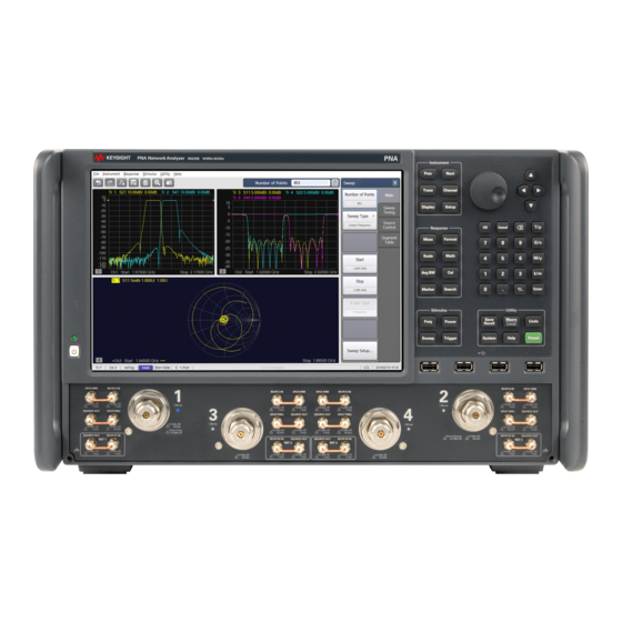
Keysight - N5224/5/7B PNA
and N5244/5/7B PNA-X
Models
Add Direct Digital
Synthesizer Capability (DDS)
For Version 7 Synthesizers -
Installation Note
To Upgrade 4-Port N5224/5/7B and N5244/5/7B
Series to 4-Port with DDS Upgrade Kit Order
Numbers:
N5224BU-4S7(for N5224B),
N5225BU-4S7(for N5225B),
N5227BU-4S7 (for N5275B),
N5244BU-4S7 (For N5244B),
N5245BU-4S7 (For N5245B), and
N5247BU-4S7 (For N5247B)
Keysight Kit Number: N5225-60143
This is the Installation Guide for the 4-port N5224/5/7B and N5244/5/7B Series Microwave Network Analyzers to a 4-port with
Version 7 synthesizers.
INSTALLATION NOTE
)
Advertisement


Need help?
Do you have a question about the N5224B PNA and is the answer not in the manual?
Questions and answers