Table of Contents
Advertisement
Quick Links
Keysight B-Series FieldFox Analyzers
This manual provides documentation for the following models:
N9913B, N9914B, N9915B, N9916B, N9917B, N9918B
N9933B, N9934B, N9935B, N9936B, N9937B, N9938B
N9950B, N9951B, N9952B
N9960B, N9961B, N9962B
This B Series User's Guide, p/n N9938-90003, is an abridged
version of the User's Guide, p/n N9938-90006. Some cross-
references in this abridged version refer to chapters and sections in
the unabridged User's Guide that can be found here:
https://literature.cdn.keysight.com/litweb/pdf/N9938-90006.pdf
User's Guide (Abridged)
Advertisement
Table of Contents

Related Manuals for Keysight B Series


Summary of Contents for Keysight B Series
- Page 1 N9933B, N9934B, N9935B, N9936B, N9937B, N9938B N9950B, N9951B, N9952B N9960B, N9961B, N9962B This B Series User’s Guide, p/n N9938-90003, is an abridged version of the User’s Guide, p/n N9938-90006. Some cross- references in this abridged version refer to chapters and sections in the unabridged User’s Guide that can be found here:...
- Page 2 Notices DOCUMENT THAT CONFLICT WITH writing elsewhere in the EULA. THESE TERMS, THE WARRANTY Keysight shall be under no obligation TERMS IN THE SEPARATE to update, revise or otherwise modify © Keysight Technologies, Inc. the Software. With respect to any AGREEMENT WILL CONTROL.
- Page 3 URLs, according to the name of your product: http://www.keysight.com/find/fieldfox To receive the latest updates by email, subscribe to Keysight Email Updates at the following URL: http://www.keysight.com/find/MyKeysight Information on preventing instrument damage can be found at: www.keysight.com/find/PreventingInstrumentRepair...
- Page 4 A.12.2x Firmware – Release B Series FieldFox For customers upgrading FieldFox firmware, the following is a list of changes from the previous release: — N9950/1/2B Microwave VNA and Spectrum Analyzer and N9960/1/2B Microwave Spectrum Analyzer FieldFox support — Improved OTA —...
- Page 5 If you do not have access to the Internet, please contact your Keysight field engineer. In any correspondence or telephone conversation, refer to the Keysight product by its model number and full serial number. With this information, the Keysight representative can determine whether your product is still within its warranty period.
-
Page 7: Table Of Contents
Resolution (Number of Data Points) ......... 44 Keysight N9938-90003 User’s Guide... - Page 8 IF Bandwidth ............77 Keysight N9938-90003 User’s Guide...
- Page 9 Custom Radio Standards ..........112 Keysight N9938-90003 User’s Guide...
- Page 10 Channel Power (CHP) ........... .159 Keysight N9938-90003 User’s Guide...
- Page 11 Run/Hold ..............216 Keysight N9938-90003 User’s Guide...
- Page 12 SA...............243 Keysight N9938-90003 User’s Guide...
- Page 13 Standard Capacity Battery (N9910X-870)........288 Keysight N9938-90003 User’s Guide...
- Page 14 Safety..............300 Acoustic Statement (European Machinery Directive) ......301 Keysight N9938-90003 User’s Guide...
-
Page 15: Overview
Keysight Handheld Analyzers N99xxB User’s Guide Overview Models and Options Table 1-1 Models Model Max Freq Description (GHz) N9913B Vector Network Analyzer AND Spectrum Analyzer N9914B Vector Network Analyzer AND Spectrum Analyzer N9915B Vector Network Analyzer AND Spectrum Analyzer N9916B... -
Page 16: Accessories
17 mm torque wrench N9910X-887 Replacement Fan Kit Although not supplied, a USB keyboard and mouse CAN be used with the FieldFox. To see a complete list of accessories that are available for the FieldFox, please visit: http://www.keysight.com/find/fieldfox. Keysight N9938-90003 User’s Guide... -
Page 17: Fieldfox Manuals, Software, And Supplemental Help
Denotes a hazard. It calls attention to a procedure that, if not correctly performed or adhered to, would result in damage to or destruction of the product. Do not proceed beyond a caution note until the indicated conditions are fully understood and met. Keysight N9938-90003 User’s Guide... - Page 18 Denotes a hazard. It calls attention to a procedure which, if not correctly performed or adhered to, could result in injury or loss of life. Do not proceed beyond a warning note until the indicated conditions are fully understood and met. Keysight N9938-90003 User’s Guide...
-
Page 19: Preparing For Initial Use Of Your New Fieldfox
FieldFox. Various AC power cables are available from Keysight that are unique to specific geographic areas. You can order additional AC power cables that are correct for use in different areas. For the power cord part number information please visit: http://www.keysight.com/find/fieldfox... -
Page 20: Install The Lithium-Ion Battery
Learn more about the lithium-ion battery in Chapter 32, “Working with the Lithium-Ion Battery.” Battery charge status is viewable: — In the upper-right corner of the screen. — On the Battery screen. To access the screen, select System, Service Diagnostics, and Battery. Keysight N9938-90003 User’s Guide... -
Page 21: Fieldfox On/Off Settings
— To turn power ON, briefly press the power button. Boot-up takes about 1 minute. — To switch to Standby mode (low battery drain), briefly press the power button. See the Note above concerning Stand By. Keysight N9938-90003 User’s Guide... -
Page 22: Power Button Led Status
FieldFox. Do NOT store the FieldFox in the soft-case while powered ON or in Standby mode. How to monitor the internal FieldFox temperature: — Press System, then Service Diagnostics. — Then Internal Temperatures. Keysight N9938-90003 User’s Guide... -
Page 23: Temperature Control Mode
For RTSA mode (where duty cycling is not possible), you will see the following messages displayed for ~3 seconds: "Entering Auto Protect mode for thermal management" Later if the temperatures are reduced: "Temperatures reduced, exiting Automatic Protect Mode" Keysight N9938-90003 User’s Guide... - Page 24 2-2). See also, Table 2-1 on page When you exit the Auto Protect (Maximum) Threshold control mode, the following message is displayed: "Temperatures reduced, exiting Maximum Auto Protect mode" Figure 2-2 Exiting Maximum Auto Protect mode message—(~62.5°C) Keysight N9938-90003 User’s Guide...
-
Page 25: High-Temp Shutdown Warning (Rtsa Mode Only)
~75.5°C. At above ~78°C, High-Temperature Shut down will engage and turn OFF the FieldFox. Refer to Figure 2-3. See also, Table 2-1 on page Figure 2-3 Shutdown Warning message—(above ~77°C) - (RTSA Mode Only!) Keysight N9938-90003 User’s Guide... -
Page 26: Avoid Overpowering The Fieldfox
FieldFox, may damage the instrument input circuitry. To avoid such damage, it is recommended to dissipate any static charges by temporarily attaching a short to the cable or antenna prior to attaching to the FieldFox. Keysight N9938-90003 User’s Guide... -
Page 27: Take The Fieldfox Tour
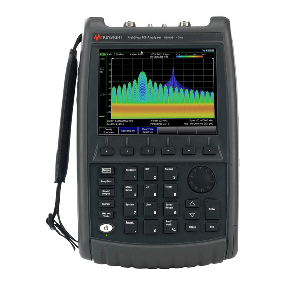
Preparing for Initial Use of Your New FieldFox Take the FieldFox Tour Take the FieldFox Tour Front Panel Keysight N9938-90003 User’s Guide... - Page 28 Displays a sub-menu for marker functions “All about Markers” page 190 Exits and closes the Active Entry dialog box or clears the character input Save/Recall Saves the current trace or recalls saved data from memory “Saving Recalling Files” on page 266 Keysight N9938-90003 User’s Guide...
- Page 29 Alternative color modes exist that maximize viewing in direct sunlight conditions, as well as other conditions such as nighttime work. Clean the Transflective screen with gentle and minimal wiping using Isopropyl alcohol applied to a lint-free cloth. Keysight N9938-90003 User’s Guide...
-
Page 30: Top Panel
N9910X-825. Other GPS antennas can also be used. Ref In SMA (f) connector for use with Frequency Reference Source and External “Frequency Reference Trig In Trigger Input signal. Source” on page 250. “Triggering” on Maximum: 5.5 VDC. page 136 Keysight N9938-90003 User’s Guide... -
Page 31: Right Side Panel
Two standard USB connectors used to connect a power sensor for Power “Saving and Recalling Meter Mode. Also used to save files to a USB flash drive. Files” on page 266 IMPORTANT! It is recommended that only USB certified cables are used with the FieldFox. Keysight N9938-90003 User’s Guide... -
Page 32: Left Side Panel
DC Voltage Source for use with external DC Bias. “Variable Voltage Source (Opt. 309)” on page 251 DC power connector used to connect to the AC/DC adapter. Maximum: 19 “Internal Charging with VDC, 4 ADC. the AC/DC Adapter ” on page 731 Keysight N9938-90003 User’s Guide... -
Page 33: Screen Tour
Data / Mem Display (CAT and NA) “All about Trace Math” Step / FFT (SA) on page 210 “Resolution Bandwidth (Res BW)” on page 128 Resolution Setting Mode dependent Measurement Start Freq or Distance Mode dependent Keysight N9938-90003 User’s Guide... - Page 34 “Date and Time” on page 236 Marker Readout “All about Markers” on page 190 Battery Status “Viewing the Battery Charge Status” on page 729 Measurement Type (CAT and NA) acquisition Mode dependent Reference Position Mode dependent Keysight N9938-90003 User’s Guide...
-
Page 35: How To Enter Numeric Values
Select Frequency multipliers as follows: — Gigahertz (1e9 Hertz) — Megahertz (1e6 Hertz) — Kilohertz (1e3 Hertz) — Hertz Select Time multipliers as follows: — Seconds — milliseconds (1e–3) — microseconds (1e–6) — nanoseconds (1e–9) — picoseconds (1e-12) Keysight N9938-90003 User’s Guide... -
Page 36: Connector Care
In addition, a dirty or damaged connector can destroy connectors that are mated to it. For this reason, NEVER use a damaged connector. See also http://na.support.keysight.com/pna/connectorcare/Connector_Care.htm Keysight N9938-90003 User’s Guide... -
Page 37: Cat (Cable And Antenna Test) Mode
Keysight Handheld Analyzers N99xxB User’s Guide CAT (Cable and Antenna Test) Mode CAT Mode is typically used to test an entire transmission system, from the transmitter to the antenna. This process is sometimes referred to as Line Sweeping. CAT Mode is similar to NA (Network Analyzer) Mode. - Page 38 Chapter 6, “Calibration for NA, CAT, and VVM Modes”, on page 87 “All about Markers” on page 190 “All about Limit Lines” on page 205 “All about Trace Math” on page 210 Making 75Ω (ohm) Measurements at the FieldFox Supplemental Online Help: http://na.support.keysight.com/fieldfox/help/SupHelp/FieldFox.htm Keysight N9938-90003 User’s Guide...
-
Page 39: Cat Mode Settings
The higher the trace is on the screen, the more energy being reflected back to the FieldFox. — DTF (VSWR) Distance to Fault in VSWR format. Keysight N9938-90003 User’s Guide... -
Page 40: Quick Settings Table
Settings table to a position relative to the trace window. The Dock Window setting persists through a Preset. Choose from the following — Full (Default setting) Only the Settings table is shown on the screen. The trace window is temporarily not shown Keysight N9938-90003 User’s Guide... -
Page 41: Frequency Range
Automatically adjusts the Y-axis to comfortably fit the Minimum and Maximum amplitude of the trace on the screen. 2. Set Scale, acquisition, and Reference Position: — Scale Manually enter a scale per division to view specific areas of the trace Keysight N9938-90003 User’s Guide... -
Page 42: Averaging
To achieve the highest dynamic range, select NA mode and reduce the IF Bandwidth setting. Learn more about dynamic range in “Increase Dynamic Range” on page 86 How to set Trace Averaging — Press BW 2. Keysight N9938-90003 User’s Guide... -
Page 43: Smoothing
--> while the sweep occurs — Continuous Makes continuous sweeps. This is the typical setting when battery power is not critical. You can also use Run / Hold +/- to toggle between Single and Continuous. Keysight N9938-90003 User’s Guide... -
Page 44: Resolution (Number Of Data Points)
Chapter 1, “Overview.” How to set Sweep Time — Press Sweep 3. — Then Min Swp Time. — Enter a value using the numeric keypad. — Press a multiplier key. Learn more in “Multiplier Abbreviations” on page Keysight N9938-90003 User’s Guide... -
Page 45: Output Power
To achieve a flattened output power, reduce the power level or stop frequency. — Then press Power Level — Then enter a value using the numeric keypad, the arrows, or the rotary knob. — Press Enter. Keysight N9938-90003 User’s Guide... -
Page 46: Interference Rejection
— The Return Loss measurement frequency settings are made in the usual manner. Learn how at “Frequency Range” on page 41. When a new Start or Stop frequency is selected, Coupled Frequency is automatically set to OFF. Keysight N9938-90003 User’s Guide... - Page 47 CAT (Cable and Antenna Test) Mode CAT Mode Settings — The DTF measurement is made using the frequencies as determined by the DTF Frequency Mode setting. Learn more in “DTF Measurement Settings” on page Keysight N9938-90003 User’s Guide...
-
Page 48: Return Loss Measurements
A deteriorated cable is not usually apparent in a Distance to Fault measurement, where more obvious and dramatic problems are identified. A Cable Loss measurement is necessary to measure the accumulated losses throughout the length of the cable. Keysight N9938-90003 User’s Guide... -
Page 49: How To Make A 1-Port Cable Loss Measurement
12.Remove the LOAD and leave the end of the cable to be tested open. 13.Press Data Math then Data – Mem. The ripple in the measurement is removed. These minor imperfections in the cable should not be considered in the Cable Loss measurement. Keysight N9938-90003 User’s Guide... -
Page 50: 2-Port Insertion Loss Measurements
— Connect the DUT and view the insertion loss measurement results. When measuring very long lengths of cable, it may be necessary to increase the sweep time. Learn how on page 44. Learn why in the Supplemental Online Help: http://na.support.keysight.com/fieldfox/help/SupHelp/FieldFox.htm Keysight N9938-90003 User’s Guide... - Page 51 Keysight Handheld Analyzers N99xxB User’s Guide DTF (Distance to Fault) Measurements CAT Mode Distance to Fault (DTF) measurements are generally used to locate problems, or faults, in a length of cable or transmission line. In this chapter, the cable to be tested is referred to as the DUT (Device Under Test).
-
Page 52: Dtf (Distance To Fault) Measurements How To Make Dtf Measurements
“How to Perform a Calibration” on page 7. Disconnect any components or antenna that should NOT be measured and connect a LOAD at the end of the DUT. 8. Press Meas Setup 4 then DTF Cable Specifications. Keysight N9938-90003 User’s Guide... - Page 53 10. Connect the start end of the DUT to the FieldFox. 11. Press Meas Setup 4 then Settings then Next Page. If the Alias-free Range setting is False, then you may see Alias faults on the screen. Learn more page Keysight N9938-90003 User’s Guide...
-
Page 54: Dtf Measurement Settings
Faults are displayed on the Y-axis in return loss format, expressed as a positive number in dB. — DTF (VSWR) Faults are displayed on the Y-axis in SWR. Learn more about SWR at the FieldFox Supplemental Online Help: http://na.support.keysight.com/fieldfox/help/SupHelp/FieldFox.ht Keysight N9938-90003 User’s Guide... -
Page 55: Dtf Start And Stop Distance
Frequency Mode — Choose one of the following: — Lowpass The frequency range of a DTF measurement is set automatically based on the Start and Stop Distances. Use Lowpass mode when the DUT is a cable ONLY. Keysight N9938-90003 User’s Guide... -
Page 56: Coupled Frequency
Coupled Frequency When a Return Loss & DTF measurement is present, this setting allows you to have different frequency ranges for each measurement. Learn more in “Coupled Frequency” on page Keysight N9938-90003 User’s Guide... -
Page 57: Cable (Correction) Specifications
Cable Loss and Velocity factor can be entered using one of the following methods: — Manually enter cable loss and velocity factor for the measurement. — Select or create a cable file which contains the cable loss and velocity factor. With a DTF measurement present: Keysight N9938-90003 User’s Guide... - Page 58 “How the Freq/Loss pairs are applied” below. — Optionally choose from the following: — Previous / Next Page Quickly scrolls through pages of Freq/Loss data. — Add Data Add a blank Freq/Loss pair to the table, Keysight N9938-90003 User’s Guide...
- Page 59 When the cable file contains two or more Freq/Loss pairs, the Loss value that is used is interpolated from the Freq/Loss pairs and the DTF center frequency. For example, using a cable file with the following Freq/Loss pairs: 1 GHz: 0.1 dB/m 2 GHz: 0.2 dB/m Keysight N9938-90003 User’s Guide...
-
Page 60: Window Settings
(Default setting) — Medium – Compromise between Minimum and Maximum window settings. — Minimum – Best Response Resolution, providing the ability to resolve between two closely-spaced responses. — Then press Done Edit. — Again press Done. Keysight N9938-90003 User’s Guide... -
Page 61: Dtf Units
An alias fault is not a true device response. An alias fault appears because of the method used to convert frequency to time. On the DTF Settings page (above) the c - Alias-free Range = Off setting indicates alias images MAY appear on the screen. Keysight N9938-90003 User’s Guide... - Page 62 FieldFox. Re-reflections are measured at the FieldFox as mirror images of the original faults. The largest fault is the open end of the cable. To avoid confusion, set the Stop distance shortly after that fault. Keysight N9938-90003 User’s Guide...
-
Page 63: Na (Network Analyzer) Mode
Keysight Handheld Analyzers N99xxB User’s Guide 5 NA (Network Analyzer) Mode Learn more about NA Mode measurements in the FieldFox Supplemental Online Help: http://na.support.keysight.com/fieldfox/help/SupHelp/FieldFox.htm. In this Chapter “About S-parameters” on page 65 “Mixed-Mode S-Parameters” on page 66 “Parameter Conversion” on page 67 “Receiver Measurements”... - Page 64 “Why and When to Calibrate” on page 88 “All about Markers” on page 190 “All about Limit Lines” on page 205 “All about Trace Math” on page 210 Learn how to make 75Ω (ohm) Measurements in the Supplemental Online Help: http://na.support.keysight.com/fieldfox/help/SupHel p/FieldFox.htm Keysight N9938-90003 User’s Guide...
-
Page 65: Na Mode Settings
When the source comes from port 2, the measurement is said to be in the reverse direction S11 and S22 reflection measurements are used to measure the amount of reflections off the corresponding DUT port. Low reflections means there is a good impedance match between the source and DUT. Keysight N9938-90003 User’s Guide... -
Page 66: Mixed-Mode S-Parameters
Because the FieldFox has only two test ports, only reflection measurements are available. Connect the balanced input or output of your DUT to the FieldFox ports 1 and 2 For highest accuracy, a Full 2-port calibration is required. Keysight N9938-90003 User’s Guide... -
Page 67: Parameter Conversion
S21 and S12. When the S-parameter is changed, the appropriate conversion changes automatically. ——Refl The displayed S-parameter is converted to Z or Y reflection, regardless of whether the S-parameter is reflection (S11 or S22) or transmission (S21 or S12). Keysight N9938-90003 User’s Guide... -
Page 68: Receiver Measurements
The FieldFox sets the source port based on the selected receiver. —Port 1 Select when measuring transmission at B receiver. —Port 2 Select when measuring reverse transmission at A receiver. Learn more about Raw Receiver Measurements at the FieldFox Supplemental Online Help: http://na.support.keysight.com/fieldfox/help/SupHelp/FieldFox.htm Keysight N9938-90003 User’s Guide... -
Page 69: Multi-Trace Configurations
IMPORTANT! For CAT and NA modes, limit lines do not apply where F1 = F2. — By default, a marker is created on ALL traces. However, they can be created individually by disabling Coupled Markers. Learn more in “Coupled Markers (NA Mode)” on page 193. Keysight N9938-90003 User’s Guide... -
Page 70: Quick Settings
Both CAT and NA Modes allow you to view and change most relevant settings from a single location. All of these settings are discussed in this chapter and, unless otherwise noted, ALL of these settings can also be made using the standard softkey menus. Keysight N9938-90003 User’s Guide... -
Page 71: Calibration Settings
“Waveguide Calibrations” on page 101. How to view and change Calibration Settings — Press Meas Setup 4. — Then Calibration Settings — Make these settings in the same manner as Quick Settings in the previous section. Keysight N9938-90003 User’s Guide... -
Page 72: Format
——Learn more about Group Delay measurements at the FieldFox Supplemental Online Help: http://na.support.keysight.com/fieldfox/help/SupHelp/FieldF ox.htm —Real Displays only the real (resistive) portion of the measured complex data. The Y-axis is Unitless. Often used for Time Domain measurements. Keysight N9938-90003 User’s Guide... -
Page 73: Frequency Range
Abbreviations” on page Scale Settings Adjust the Y-axis scale to see the relevant portions of the data trace. The Y-axis is divided into 10 graticules. This setting can be changed at any time without affecting calibration accuracy. Keysight N9938-90003 User’s Guide... -
Page 74: Magnitude Offset
The Magnitude offset setting affects only the active trace. How to set Magnitude Offset — Press Scale / Amptd — Then More — Then Magnitude Offset - Offsets the entire data trace by the specified value. Keysight N9938-90003 User’s Guide... -
Page 75: Electrical Delay
360°. Use this feature in the following ways: Improve the display of a phase measurement. This is similar to the way you would change the acquisition in an amplitude measurement. Change the phase response to center or the response on the screen. Keysight N9938-90003 User’s Guide... -
Page 76: Averaging
<n> consecutive sweeps. The average counter shows the number of previous sweeps that have been averaged together to form the current trace. When the counter reaches the specified count, then a ‘running average’ of the last <n> sweeps is displayed. Keysight N9938-90003 User’s Guide... -
Page 77: If Bandwidth
When enabled, appears on the FieldFox screen. How to set Smoothing — Press BW 2 — Then Smoothing ON OFF — Then Sm. Aperture and enter a value between 0 and 25 (percent) using the numeric keypad. Keysight N9938-90003 User’s Guide... -
Page 78: Single Or Continuous Measure
— Then choose from the following: 101 |201 1001 1601 4001 | 10001. — Using SCPI, Resolution can be set to ANY number of points between 3 and 10001. See the Programming Guide at http://na.support.keysight.com/fieldfox/help/Programming/webhelp/FFP rogrammingHelp.htm Keysight N9938-90003 User’s Guide... -
Page 79: Sweep Time
(External) A sweep is initiated on the rising or falling edge of an external TTL signal at the Ref In/Trig In connector on the FieldFox top panel. ——When the FieldFox is armed for an external trigger signal, Wait is annotated on the display. Keysight N9938-90003 User’s Guide... - Page 80 S11 and S22 together on the display — When point mode trigger is already enabled, if conditions are changed requiring forward and reverse sweeps, an error "Error: Point trigger not compatible with 2-port cal." will be displayed and point mode Keysight N9938-90003 User’s Guide...
-
Page 81: Output Power
— High Sets output power to the maximum achievable power at all displayed frequencies. Output power is NOT FLAT across the displayed FieldFox frequency span. Please see “Specifications/Data Sheet” on page 761 for expected power levels. Keysight N9938-90003 User’s Guide... -
Page 82: System Impedance (Z0)
Also use port extensions if you have already performed a calibration, and then decide that you need to add a length of transmission line in the measurement configuration. Use port extensions to “tell” the FieldFox that you have added the length to a specific port. Keysight N9938-90003 User’s Guide... -
Page 83: Velocity Factor
The electrical delay or port extension value is entered as delay, or electrical length, in units of time. Entering the velocity factor causes the FieldFox to accurately display the equivalent physical length in meters (NOT available in feet) that corresponds to the entered electrical delay. Keysight N9938-90003 User’s Guide... -
Page 84: Big Marker Display States (A And B)
Edit Big Marker (A or B) — Then edit the following display state settings: — Num Traces – Choose the Multi-Trace configuration x1, x2, or x3. Only Overlayed configurations are allowed. Learn more in “Multi-Trace Configurations” on page Keysight N9938-90003 User’s Guide... - Page 85 Lin using the standard menu (Meas 1, Format), the setting will show on the display. But if you then use the Big Readout (A | B | OFF) setting, when B is recalled, the Lin setting will be overwritten with the original Log setting. Keysight N9938-90003 User’s Guide...
-
Page 86: Increase Dynamic Range
The results you see will depend on the performance of your DUT. With an S21 trace active: 1. With RF OUT (port-2) open, press Trace 6 then Math and Memory then Data->Mem 2. Re-connect the DUT. 3. Press Data Math then Data-Mem Keysight N9938-90003 User’s Guide... -
Page 87: Chapter 6, "Calibration For Na, Cat, And Vvm Modes
Keysight Handheld Analyzers N99xxB User’s Guide Calibration for NA, CAT, and VVM Modes Calibration removes the systematic errors that are associated with measurements in NA, CAT, and VVM Modes. Key presses are identical in all of these Modes. In this Chapter “Why and When to Calibrate”... -
Page 88: Calibration For Na, Cat, And Vvm Modes
DUT port during some measurements. — SHORT and OPEN standards both cause 100% of an RF signal to be reflected. The difference between these two standards is what happens to the phase of the reflected signal, which is beyond the Keysight N9938-90003 User’s Guide... -
Page 89: Calready
When performing a calibration that contains a large number of points (5000 to 10,001 points) be aware that the calibration progress bar may not move for 2 or 3 minutes during the calibration process. In CAT, NA, or VVM Mode, press Cal 5. Keysight N9938-90003 User’s Guide... - Page 90 You can ignore the “Source Unleveled” error, or to avoid the error, select either High power or -15 dBm before calibrating. Learn more about setting Output Power in “Output Power” on page 45 Keysight N9938-90003 User’s Guide...
-
Page 91: Mechanical Cal
Mechanical Calibration is performed using discrete standards from a Cal Kit. Several Cal Kit definitions are built into the FieldFox. To learn about Cal Kit definitions, refer to the Application Note, “Specifying Calibration Standards and Kits for Keysight Vector Network Analyzers,” available online at http://literature.cdn.keysight.com/litweb/pdf/5989-4840EN.pdf Visit www.keysight.com/find/fieldfoxsupport... - Page 92 Learn more about Cal Types in “Calibration Type” on page To select a different Cal Type: — Press Change Cal Type. — Then using the arrows or rotary knob, select a Cal Type, — Then press Select and Finish. Begin Calibration Keysight N9938-90003 User’s Guide...
-
Page 93: Ecal
Cal Kit covers the frequency range of the measurement. You can verify the frequency range of your Cal Kit at: www.keysight.com/find/fieldfoxsupport. Click Cal Kits. — Follow the Cal Wizard prompts. Connect the specified standard at the point where the DUT will be connected, then press Measure. - Page 94 Mechanical Cal Setup page of the CalWizard. However, a User Characterization can NOT be PERFORMED using the FieldFox. It must be performed using a bench top Keysight VNA, such as the PNA or ENA. Learn more about User Characterization at the PNA Help website: http://na.support.keysight.com/pna/help/latest/S3_Cals/ECal_User_Charact...
- Page 95 If the frequency is adjusted outside of the set of points calibrated the error correction is turned off and the following message is displayed: "Error correction disabled. Stimulus outside calibrated range." Keysight N9938-90003 User’s Guide...
-
Page 96: Simple Response Cals
CalReady are updated to account for the THRU that is used during the normalization process. How to perform a Simple Response Cal — Select the measurements to be calibrated. See the relevant Mode (NA, CAT, or VVM) for measurement selections. Keysight N9938-90003 User’s Guide... -
Page 97: View Cal
Response Cal on Port 2 is performed, CAL ON U is shown for an S22 measurement only. View Cal From the Choose Calibration screen (see “How to Perform a Calibration” on page 89), press View Cal to see the following screen: Keysight N9938-90003 User’s Guide... -
Page 98: Calibration Type
Sweep Directions – Both FULL 2-Port Cals listed below result in correction that requires background measurements sweeps in both directions, regardless of the displayed measurements. The displayed traces are updated at a slower rate than Enhanced Response and 1-port calibrations, which require sweeps in one direction only. Keysight N9938-90003 User’s Guide... - Page 99 Also select an Enhanced Response Optimization. Learn more in “Enhanced Response Optimization” on page 102. TRL – Mechanical Cal ONLY A complete 2-Port calibration with potentially better accuracy than Full 2-port. Corrects all S-parameters. DUT: Non-Insertable or Insertable Keysight N9938-90003 User’s Guide...
-
Page 100: Isolation Step
How to perform the Isolation step — Press Cal 5 then Mechanical Cal / ECal — Then Advanced — Then Omit Isolation — Perform the Isolation step — (default) Omits the Isolation step — Then <Back Keysight N9938-90003 User’s Guide... -
Page 101: Waveguide Calibrations
Otherwise, an error message will appear during the ‘Calculating Steps’ portion of the calibration. Waveguide Cal Kits Keysight sells two waveguide Cal Kit series: the premium 11644A series and the economy N9911X series. Both are available online at www.Keysight.com Effective Velocity Factor Velocity factor is the speed at which an electromagnetic signal passes through the transmission medium relative to the speed of light. -
Page 102: Enhanced Response Optimization
CalReady, this setting optimizes the calibration based on the type of DUT being measured. See also: CalReady Properties in “CalReady” on page This setting does NOT survive Preset. — Press Cal 5 then More — Then Enh.Response Keysight N9938-90003 User’s Guide... -
Page 103: Interpolation
The FieldFox can have only ONE calibration present for all modes. Because NA, CAT, and VVM modes are very similar, a calibration that is performed in one mode can also be applied in the other modes with the same type of measurements (1-port or 2-port). Keysight N9938-90003 User’s Guide... -
Page 104: Save The Calibration
Data & Memory. — Press Cal 5 then More — Select a CalReady Cal to compare with the current setting. — Press Esc to exit the cal menu. — View the differences in the two traces. Keysight N9938-90003 User’s Guide... -
Page 105: Verifying Calibration And Jumper Cable Integrity
— If the measurement trace is relatively stable, the jumper cable is of good quality. — If you observe significant movement in the peaks of the measurement trace when moving the cable (>5 dB), the jumper cable may need to be replaced. Keysight N9938-90003 User’s Guide... -
Page 106: Calibration Method Summary
— When the temperature changes more than about 10°F (5°C) — When the connection to the DUT requires a different jumper cable or adapters. — When any of the following measurement settings change: Frequency Range, Power Level, IF BW, and Resolution. Keysight N9938-90003 User’s Guide... -
Page 107: Sa (Spectrum Analyzer) Mode (Option 233-Mixed Analyzers)
Keysight Handheld Analyzers N99xxB User’s Guide SA (Spectrum Analyzer) Mode (Option 233–Mixed Analyzers) To better reflect the enhancements implemented during the alignment > process, for firmware versions A.10.15 "IF Flatness Alignment" is now referred to as "Channel Equalization" or "Channel Equalization Alignment"... - Page 108 “Triggering” on page 136 “FFT Gating (Opt 238)” on page 139 “Single / Continuous / Restart” on page 141 “Points ” on page 141 “Trace Display States (SA Mode)” on page 141 “Average Type” on page 142 Keysight N9938-90003 User’s Guide...
- Page 109 “Spectrogram Display (SA Option)” on page 458 “Waterfall Display” on page 461 “Record/Playback (SA Option)” on page 463 Optional Settings: “All about Markers” on page 190 “All about Limit Lines” on page 205 “Saving and Recalling Files” on page 266 Keysight N9938-90003 User’s Guide...
-
Page 110: Sa Mode Settings
The FieldFox can be used with an OML frequency extender. Refer to “Utilities” on page 222, the B Series FieldFox Configuration Guide 5992-3701EN, and to “Contacting Keysight” on page Available ONLY with Opt. 209 and while in Step sweep, SA mode allows reverse sweeps. - Page 111 Selects the entire frequency span of the FieldFox. The Center frequency is set automatically. How to change frequency step size When using the arrows to change any of the frequency settings, the size of the frequency step can be changed. Keysight N9938-90003 User’s Guide...
-
Page 112: Radio Standard
Custom Radio Standards Your own custom Radio Standards can be imported into the FieldFox. Custom standards are created in *.csv (spreadsheet) format. A template and instructions for creating your custom Radio Standard is at: http://na.support.keysight.com/fieldfox/help/SupHelp/Reference/CustomRa dioStandard.htm Keysight N9938-90003 User’s Guide... -
Page 113: Channel Selection
CF Step alters to Channel Step. How to change the Channel Number of the Measurement With Unit = Chan the FieldFox will NOT allow you to specify channels outside of the selected Radio Standard. — Press Freq/Dist Keysight N9938-90003 User’s Guide... - Page 114 — (−) indicates that the lowest frequency in the channel (128) is at the left edge of the screen. — (+) indicates that the highest frequency in the channel (130) is at the right edge of the screen. Keysight N9938-90003 User’s Guide...
-
Page 115: Reverse Swap
Press Scale / Amptd. Then choose from the following: — Scale Type [current setting] —Log Logarithmic scale (default setting). The Y-axis reference line represents the specified absolute acquisition in the current Unit selection. Y-axis graticules show dB below or above the reference line. Keysight N9938-90003 User’s Guide... -
Page 116: External Gain
When RF Atten is set to Auto, you may see a change in the RF Attenuation value. This is an attempt to measure the signal at top of screen (the acquisition) without overloading the SA first mixer. Keysight N9938-90003 User’s Guide... -
Page 117: Attenuation Control
RF Attenuation is set manually. The default Attenuation setting is 10 dB. Enter a value between 0 to 40 dB in 5 dB steps using the numeric keypad, the arrows, or the rotary knob. Then press Enter Keysight N9938-90003 User’s Guide... -
Page 118: Preamplifier Control (Opt 235)
FieldFox receiver. —If the signal level DOES increase, then the receiver was compressed. Set the RF Attenuation value at the setting when further increases no longer result in an increase in the displayed power level. Keysight N9938-90003 User’s Guide... -
Page 119: Field Strength Measurements
All Correction ON/OFF states survive a Mode Preset, but NOT a Preset. — Press Scale/Amptd. — Then More — Then Corrections — Then choose from the following: —Apply Corrections Auto Disabled Use Auto and Disabled correction for all settings. Keysight N9938-90003 User’s Guide... -
Page 120: Using The Antenna/Cable Editor
“Set File Type and Select Device” on page 271. When finished, press Back to return to the previous menu. Using the Antenna/Cable Editor The Antenna Editor and the Cable Editor menus are very similar. Both tables include header information, and a Frequency/Value table. Keysight N9938-90003 User’s Guide... - Page 121 — To edit Frequency/Value pairs, enter numbers using the numeric keypad, and a frequency suffix when necessary. ——For both Cable and Antenna correction, Positive numbers indicate loss (we need ADD something positive to compensate for it), and Negative is indicative of some existing gain. Keysight N9938-90003 User’s Guide...
- Page 122 — If the folder does not already exist on a USB or SD card, it is created automatically before storing the file. — All SA mode Antenna and Cable files are saved and recalled as *.csv files, which allows them to also be read by spreadsheet programs. Keysight N9938-90003 User’s Guide...
-
Page 123: Source Tracking Offset And Offset Reversal
SA (Spectrum Analyzer) Mode (Option 233–Mixed Analyzers) SA Mode Settings — The FieldFox can also read *.ANT (Antenna) files that were created from older Keysight Spectrum Analyzers. — SA Mode cable or antenna (*.csv or *.ANT) files can NOT be edited in Data Link software. -
Page 124: Tune & Listen (Am/Fm)
— Then Analog Demod Tune & Listen — Then choose a demodulation type. Select a setting based on the type of interfering signal you suspect is being broadcast. —None Turns Tune & Listen OFF —AM Amplitude Modulation Keysight N9938-90003 User’s Guide... - Page 125 To select Listen Time: — Press Meas Setup 4 — Then Listen Time — Enter a value using the numeric keypad, arrows, or the rotary knob. Then select a multiplier key. Learn about multiplier abbreviations. Keysight N9938-90003 User’s Guide...
-
Page 126: Independent Source/Tracking Generator
To view the internal source, you must connect a cable or device between the RF Output connector and the RF Input connector. How to make Independent Source Settings — Press Measure 1 — Then Source — Source Enable ON OFF — Turns ON the internal source. Keysight N9938-90003 User’s Guide... - Page 127 — In the table, select Battery Saver. Press Edit then Battery Saver ON OFF To suspend InstAlign: (Learn more in “How to Access Individual Alignments” on page 148.) 1. N995xB/6xB cannot have the Leveled value set lower than –35 dBm. Keysight N9938-90003 User’s Guide...
-
Page 128: Resolution Bandwidth (Res Bw)
More smoothing occurs as the Video BW is set lower. However, as the Video BW is narrowed, the sweep speed becomes slower. How to set VBW — Press BW 2. Keysight N9938-90003 User’s Guide... -
Page 129: Sweep Type
The FieldFox uses FFT sweep type regardless of the Res BW. —Step The FieldFox uses Step sweep type regardless of the Res BW. This is useful for capturing impulsive noise that may be generated from nearby electrical equipment. Keysight N9938-90003 User’s Guide... -
Page 130: If Output
How to select IF Output The IF Output signal is useful only in Zero Span. Learn more about Zero Span in “Zero Span Measurements” on page 134. At least one sweep must be made in order to tune the FieldFox. Keysight N9938-90003 User’s Guide... - Page 131 —Wide Requires B04 or B10. The IF output signal has approximately 100 MHz bandwidth with either B04 or Option B10. Figure 7-5 SA Display Wide BW IF Out - Center Frequency 4 GHz (Requires Option B10) Keysight N9938-90003 User’s Guide...
-
Page 132: Sweep Acquisition
While watching the trace, increase the SwpAcquisition value until the pulse spectrum rises out of the noise and reaches its maximum level. Increasing the SwpAcquisition value beyond this point only slows the update rate (increases the actual Sweep time readout) but does not improve measurement quality. Keysight N9938-90003 User’s Guide... - Page 133 — Man Enter a relative acquisition value between 1 and 5000, where: ——1 = Fastest sweep possible ——5,000 = Slowest sweep possible ——# is shown in front of the actual sweep time to indicate a manual setting. Keysight N9938-90003 User’s Guide...
-
Page 134: Very Long Sweep Times
X-axis units becomes Time. The SA becomes like a tunable oscilloscope, with the center frequency being the frequency of interest. This capability is useful for analyzing modulation characteristics, such as pulsed measurements. For non-zero span measurements, refer to “Sweep Acquisition” on page 132. Keysight N9938-90003 User’s Guide... - Page 135 — Enter a value using the numeric keypad. Sweep time is limited to 1000 seconds for N991xB/2xB/3xB models. — Then select a multiplier key. Learn more in “Multiplier Abbreviations” on page Learn more about SA mode Sweep Time in the Supplemental Online Help: http://na.support.keysight.com/fieldfox/help/SupHelp/FieldFox.htm Keysight N9938-90003 User’s Guide...
-
Page 136: Triggering
However, RF Burst is not as sensitive to triggering on low-level signals. Trigger Slope Trigger Slope determines which edge of an External, Video, or RF Burst trigger signal initiates a sweep. — Press Sweep 3 — Then Trigger Settings Keysight N9938-90003 User’s Guide... - Page 137 Therefore, you may need to set the trigger level higher than the displayed level. — Press Sweep 3 — Then Trigger Settings — Then Trig Level — Enter a value using the numeric keypad, the arrows, or the rotary knob. Keysight N9938-90003 User’s Guide...
- Page 138 —OFF: Select, then enter a position value from 0 to 10 using the numeric keypad, the arrows, or the rotary knob. ——0: T-zero occurs at the left graticule. ——5: T-zero occurs at the center of the screen. ——10: T-zero occurs at the far right graticule. — Then press Enter. Keysight N9938-90003 User’s Guide...
-
Page 139: Fft Gating (Opt 238)
FFT Gating is a simple, efficient way to set the proper amount of trigger delay and capture time so that signal artifacts of a repeating waveform or pulse can be examined in the frequency domain. Learn more about trigger settings in “Triggering” on page 136. Keysight N9938-90003 User’s Guide... - Page 140 When you have properly setup the Gate Trigger, Width, and Delay using the Gate View measurement, you can turn Gate View OFF to return to the full screen non-zero span measurement with FFT Gating ON, the RBW set, and the Trigger settings active. Keysight N9938-90003 User’s Guide...
-
Page 141: Single / Continuous / Restart
— In SA Mode you can display up to four of the following types of trace states. All SA settings are applied to all displayed traces. See also “Marker Trace (IQA and SA Mode)” on page 194. Keysight N9938-90003 User’s Guide... -
Page 142: Average Type
In SA Mode, there are four different processes in which Averaging is performed: — Average Traces – Learn more in “Averaging” on page 158. — Detection Method Averaging – Learn more in “Detection Method” on page 151. Keysight N9938-90003 User’s Guide... -
Page 143: Average Count
1, perform <n> sweeps, then return to Hold. How to set Average Count — Press Meas Setup 4 — Then Average Count — Enter a value from 1 to 10,000 using the numeric keypad, the arrows, or the rotary knob. Keysight N9938-90003 User’s Guide... -
Page 144: Alignments
Individual Align. All three or a subset of the individual alignments are required for each specific mode, depending on the type of measurement supported by it: — InstAlign Amplitude Alignment — RF Burst Amplitude Alignment RTSA: Keysight N9938-90003 User’s Guide... - Page 145 Control On/Off. This enables a soft-key for access to Individual Alignments > when this preference is set to ON: Cal 5 Individual Align. For more refer to “Preferences” on page 230, in Chapter 9 System Settings. Keysight N9938-90003 User’s Guide...
- Page 146 (if its state is Hold) and requires an update or it is in the OFF state. This situation does not occur when the respective alignment is in the Auto state. To clear this Align All Now notification, press the softkey. Keysight N9938-90003 User’s Guide...
- Page 147 System Settings. The Individual Alignment softkey is only available, when the preference SA - Individual Alignment Control is set to On in the FieldFox Preferences menu. Refer to “Preferences” on page 230, in Chapter 9 System Settings. Keysight N9938-90003 User’s Guide...
- Page 148 (predetermined in the factory) or the internal instrument temperature has changed sensibly (predetermined in the factory). Keysight N9938-90003 User’s Guide...
-
Page 149: Rf Burst Amplitude Alignment
The alignment process can be disabled. You may want to do this, for example, if you are analyzing the amplitude stability of a signal. How to make Burst Alignment settings These settings do NOT survive a Preset or Mode Preset. — Press Cal 5 — Then Individual Alig Keysight N9938-90003 User’s Guide... - Page 150 (Default setting) SA measurement applications monitor changes in internal temperature and the time since last alignment update and trigger the need for a new update when the alignment becomes stale. The alignment is deemed stale after a significant Keysight N9938-90003 User’s Guide...
-
Page 151: Detection Method
From the frequency span of the measurement, the span of each data point is calculated as (frequency span / (data points-1)). The detection method allows you to choose how the measurements in each bucket are displayed. Keysight N9938-90003 User’s Guide... - Page 152 —Positive Peak [#Pk] Displays the maximum value of all the measurements in each bucket. This setting ensures that no signal is missed. However, it is not a good representation of the random noise in each bucket. Keysight N9938-90003 User’s Guide...
-
Page 153: Display Line
Display Line OFF ON — Then enter a Y-axis value using the arrows or the rotary knob, then press Enter. Or enter a value using the numeric keypad and press a suffix key or press Enter. Keysight N9938-90003 User’s Guide... -
Page 154: Noise Marker
Interval Band Marker because it averages power over a specific time interval. In this case the range is specified as the Interval Span. Learn more about Zero span measurements in “Zero Span Measurements” on page 134. Keysight N9938-90003 User’s Guide... -
Page 155: Frequency Counter At Marker
1 Hz resolution, and display the frequency of the signal peak in the marker annotation area. The marker does not move to the signal peak. When Freq Counter is ON, measurement sweeps are considerably slower. Keysight N9938-90003 User’s Guide... -
Page 156: Time Zero Fixed Marker
Therefore, it is important to scale the signals that you intend to measure between the top and bottom of the screen. Learn more about Scale in “Scale and Units” on page 115. Keysight N9938-90003 User’s Guide... -
Page 157: Meas Uncal Error
Hold mode. The annotation is changed immediately, but the trace is not updated until the next sweep occurs. Therefore, the current data trace does not match the screen annotation. See the asterisk in Figure 7-1 on page 107. Keysight N9938-90003 User’s Guide... -
Page 158: Channel Measurements
By default in ALL Channel measurements, averaging is enabled and set to display the average of the last 15 measurements. When enabled, this average setting is automatically making the following ‘averaging’ settings in order to provide the most accurate power measurements: Keysight N9938-90003 User’s Guide... -
Page 159: Traces
Only one measurement trace can be displayed in Channel Measurements. Channel Power (CHP) Channel Power measures total power over the specified Integrated BW. The Integration Bandwidth (IBW) can be adjusted to measure the power over multiple channels. Keysight N9938-90003 User’s Guide... - Page 160 When Channel Power is selected, vertical posts appear on the display to mark the current Integration Bandwidth setting. The displayed Channel Power and Power Spectral Density values are measured and calculated over the specified Integration Bandwidth. Keysight N9938-90003 User’s Guide...
- Page 161 The frequency span between the two vertical posts is the Occupied Bandwidth. The Occupied Power, the power that is contained between the two posts, is also displayed in dBm. Keysight N9938-90003 User’s Guide...
- Page 162 Frequency Span. The frequency span can be entered using arbitrary frequencies or by using a Radio Standard in conjunction with channel numbers. Learn how to select a Radio Standard and channels in “Channel Selection” on page 113. To change Frequency Span: — Press Freq/Dist Keysight N9938-90003 User’s Guide...
- Page 163 You can measure the channel power in one, two, or three adjacent (offset) channels on the low frequency and high frequency side of the carrier channel. Limits can be used to quickly see if too much power is measured in the adjacent channels. Keysight N9938-90003 User’s Guide...
- Page 164 How to select ACPR — Press Measure__1 — Then Channel Measurements — Then Adjacent Channel Power When ACPR is selected, the following settings are maintained from a previous measurement: Center Frequency, Preamp ON|OFF, and RF Attenuation. Keysight N9938-90003 User’s Guide...
- Page 165 Then enter a value using the numeric keypad. — Select Offset Integ BW This is the frequency range over which power is measured in that offset; half of the range below and half above the Offset Freq. Keysight N9938-90003 User’s Guide...
- Page 166 - dB or dBc value is computed by subtracting the measured carrier power from the measured offset power. —Man – dB or dBc value is computed by subtracting the entered RefValue from the measured offset power. Keysight N9938-90003 User’s Guide...
- Page 167 RRC Weighting is set and enabled automatically when included in a selected radio standard. To set and enable RRC Weighting: — Press Meas Setup 4 — Then RRC Weighting ON OFF — Then More — Then RRC Alpha [current setting] Keysight N9938-90003 User’s Guide...
- Page 168 SA (Spectrum Analyzer) Mode (Option 233–Mixed Analyzers) Channel Measurements — Enter a value between 0 (no smoothing) and 1 (most smoothing) using the numeric keypad, arrows, or the rotary knob. A standard level of filtering is 22. — Press Enter. Keysight N9938-90003 User’s Guide...
-
Page 169: How To Set Up Emf Settings (Requires Emf (Option 358), Gps (Option 307), And Sa Mode (Option 233-Mixed Analyzers))
If you are not familiar with this process or would like more information, refer to Chapter 14, “USB Antennas – (Full Capability Requires EMF Option 358, and either SA mode (Option 233 Mixed Analyzers) or OTA—5G NR / 5G NR EVM Conducted Option 378).” Keysight N9938-90003 User’s Guide... -
Page 170: Emf Features
EMF uses the following data formats: — Field Strength units: — dBµV/m – For use with E-field signals — dBµA/m – For use with H-field signals — dBG – dB Gauss — dBpT - dB Tesla Keysight N9938-90003 User’s Guide... - Page 171 SA (Spectrum Analyzer) Mode (Option 233–Mixed Analyzers) How to Set Up EMF Settings (Requires EMF (Option 358), GPS (Option 307), and SA Mode (Option 233–Mixed Analyzers)) Figure 7-15 Example of EMF with Triaxial Antenna Keysight N9938-90003 User’s Guide...
-
Page 172: Emf Setup Procedure
Unable to communicate with antenna. Ensure it is connected. is displayed, verify the USB antenna is connected correctly. See also, “Troubleshooting” on page 406. — Then USB Antenna [Tri Axial] verify Triaxial (default) is selected. Keysight N9938-90003 User’s Guide... - Page 173 X axis measurement (i.e., this uncorrected manual mode is typically used when no EMF Option 358 is installed). Refer Figure 7-16. See also step Figure 7-16 SysCtrl Triaxial [N] Softkey – With the X–Axis Dipole Selected Keysight N9938-90003 User’s Guide...
- Page 174 — displays a cable corrections table that you can edit with new cable correction content. ——Choose to overwrite the current cable data ——Choose to exit the cable data edit table view Keysight N9938-90003 User’s Guide...
- Page 175 X antenna factor. See also See also Chapter 9, “System Settings” and then to “Alpha Numeric Editing” on page 239. — Recall Antenna – to recall a stored X antenna factor. See also Chapter 9, “System Settings.” Keysight N9938-90003 User’s Guide...
- Page 176 — Frequency – edits the frequency value measured that corresponds to a particular Antenna Factor. — Antenna Factor – edits the Antenna Factor that corresponds to a particular frequency. Refer to next step for details on editing the antenna Settings table. Keysight N9938-90003 User’s Guide...
- Page 177 Save Antenna to save your changes. See also Chapter , “File Saving Naming Options” and then to “Alpha Numeric Editing” on page 239. For more information: — See also “GNSS (GPS+) and GPS” on page 245. Keysight N9938-90003 User’s Guide...
- Page 178 — Cable Off – to open a softkey menu to edit the cable factors for an antenna setup. 2. For this example, the Cable Off softkey menu has been selected: Keysight N9938-90003 User’s Guide...
- Page 179 Frequency and Cable Loss (i.e., you must press to deleted the rows or to exit the current softkey menu). — Back – To exit to previous softkey menu. — Press Done when finished editing to exit. Keysight N9938-90003 User’s Guide...
- Page 180 “Alpha Numeric Editing” on page 239. For more information: — See also “GNSS (GPS+) and GPS” on page 245. Figure 7-18 Example: Editing and Adding a New X axis antenna is shown. But, the Cable Loss table is similar. Keysight N9938-90003 User’s Guide...
-
Page 181: Spectrum Emission Mask (Sem) - (Sa Mode Only)
The following are displayed: — Total Power Ref (dBm / Hz) - measures total power over the specified Integrated BW. Keysight N9938-90003 User’s Guide... - Page 182 Spectrum Emission Mask (SEM) — (SA Mode Only) — Spectrum Emission Mask Pass/Fail – A PASS indicates the displayed SEM is within the current boundaries specified. A FAIL indicates the current signal fails with the specified parameters. Figure 7-19 SEM Example Keysight N9938-90003 User’s Guide...
-
Page 183: How To Select Spectrum Emission Mask (Sem) Measurement
Channel Measurements > Spectrum Emission Mask 2. Press Meas Setup 4 then optionally select: — Averaging Enable/disables averaging and sets the number of trace averages (Default is OFF). — Meas Type Then select one of the following: Keysight N9938-90003 User’s Guide... - Page 184 128. — Offsets Opens the frequency Offsets softkey menu. Then select one of the following: — Offset Sets the number of pairs of frequencies to be offset (up to eight pairs can be selected). Keysight N9938-90003 User’s Guide...
- Page 185 Press Freq/Dist then — Center - sets the center frequency. — SEM Auto Span - Enables/disables the SEM Auto Span. — Freq Span - sets the frequency span of the SEM measurement. Keysight N9938-90003 User’s Guide...
- Page 186 Absolute - The absolute mask is tested for all offsets. — Relative - The relative mask is tested for all offsets. — Abs OR Rel - Either Absolute or Relative data failure generates a fail message. Keysight N9938-90003 User’s Guide...
-
Page 187: Record/Playback (Sa Option)
- Sets all of the Offset segments (default Auto is Peak, to facilitate finding peak signal energy when comparing against the Limits). See also “Detection Method” on page 151. — Record Playback - Refer to “Record/Playback (SA Option)” on page 463. Keysight N9938-90003 User’s Guide... - Page 188 SA (Spectrum Analyzer) Mode (Option 233–Mixed Analyzers) Spectrum Emission Mask (SEM) — (SA Mode Only) Keysight N9938-90003 User’s Guide...
- Page 189 Keysight Handheld Analyzers N99xxB User’s Guide Data Analysis Features The following features can be used after a measurement to analyze the results. In this Chapter “How to create Markers” on page 190 “How to move a Marker after it is created” on page 190 “About Delta Markers”...
-
Page 190: Data Analysis Features
— Then move the marker as when it was first created. — Markers can also be moved using one of the marker search functions. Refer to “Searching with Markers” on page 196. Keysight N9938-90003 User’s Guide... -
Page 191: About Delta Markers
Peak search functions can be performed using delta markers. Figure 8-2 A Delta marker and its associated reference marker. In the graphic above, the marker readout shows the difference between the two markers in frequency and amplitude. Keysight N9938-90003 User’s Guide... -
Page 192: Signal Track Marker (Nf And Sa Mode Only)
The Marker Table can be displayed at the bottom of the FieldFox screen. It can display information for up to 6 markers in a full-width window, and up to 3 markers for a half-width window (NA mode). The marker table “squeezes” the graticule area when activated. Keysight N9938-90003 User’s Guide... -
Page 193: Coupled Markers (Na Mode)
Coupled Markers move on ALL traces at the same time (NA shown). 1. IQA mode has coupled markers, but the behavior is different than NA mode’s coupled markers. Refer to “Coupled Markers (Waveform Only)” on page 281. Keysight N9938-90003 User’s Guide... -
Page 194: Marker Colors
X-axis location on the specified trace. Learn more about IQA Traces in “Trace Display States (IQA Mode)” on page 284. Learn more about SA Traces in “Trace Display States (SA Mode)” on page 141. Keysight N9938-90003 User’s Guide... -
Page 195: Marker Format
R + jX 22.8Ω -j61.4Ω Complex impedance format (3rd number is distance for Time Domain) 287.9fF Z Magnitude 66.08Ω Impedance Mag. Phase 73.8° Real 0.2003 More Imaginary -0.6727 Mag & Phase 0.705, -73.7° dB Angle -2.1 dB, -138.2° Keysight N9938-90003 User’s Guide... -
Page 196: Searching With Markers
FieldFox interpolates between measured data points to find the exact Target value to two decimal points. The interpolated X-axis value is displayed in the marker readout or marker table. Subsequent presses of the Target softkey cause the marker to move to the right to Keysight N9938-90003 User’s Guide... - Page 197 ——If you first enter Negative, then Positive values, it may be necessary to press Marker, then More, then Markers All Off. Figure 8-4 S21 of a filter with BW Markers and associated readout values. The search criteria is -3 dB. Keysight N9938-90003 User’s Guide...
- Page 198 Peak Left (Not IQA) Moves the active marker to the next data point to the left that meets the ‘Peak’ criteria. When no data points to the left meet the ‘Peak’ criteria, the marker does not move. Keysight N9938-90003 User’s Guide...
- Page 199 DUT. Use in conjunction with marker table and limit lines to verify your DUT’s signals and to adjust or tune as needed. See also, “All about Limit Lines” on page 205. Keysight N9938-90003 User’s Guide...
- Page 200 Mkr5 & Mkr6 Search — For Mkr1 & Mkr2 maximum or minimum value search: — Then Mkr5 Peak — Mkr5 Min Or for Mkr3 & Mkr4 maximum or minimum value search: — Then Mkr6 Peak — Mkr6 Min Keysight N9938-90003 User’s Guide...
-
Page 201: What Is A 'Peak
To make these settings, create a non-DTF CAT mode measurement, then change the measurement back to DTF. How to set Peak Criteria — Press Mkr ->/Tools. — In CAT and NA modes: — Then Peak Search. — Then Peak Criteria Keysight N9938-90003 User’s Guide... - Page 202 Peak Search, including the use of peak criteria rules. See also, “Using Markers (IQA)” on page 279. ——Delta Ref Fixed Enables or disables the delta reference fixed marker. Keysight N9938-90003 User’s Guide...
-
Page 203: Marker Functions
(IQ Analyzer (NOT waveform) and SA mode ONLY) The acquisition becomes the magnitude of the active marker. — Mkr->TuneFreq (SA mode with Tune & Listen ONLY) The Tune & Listen Frequency becomes the frequency of the active marker. The following applies to DTF Measurements ONLY: Keysight N9938-90003 User’s Guide... -
Page 204: I/Q Analyzer (Iqa) Marker Functions
— Band/Interval Power Marker (Available in I/Q Analyzer mode) — Frequency Counter at Marker — Audio Beep with Marker — Time Zero Fixed Marker Learn more about these marker functions starting in the SA chapter here: “Noise Marker” on page 154. Keysight N9938-90003 User’s Guide... -
Page 205: All About Limit Lines
——Relative - the limit line moves relative to the center frequency and acquisition. Note: It is easiest to first create Fixed Limits, then change this setting to Relative. Learn more “Relative Limit Lines” on page 206. — Upper/Lower – Press Edit to toggle between the following: Keysight N9938-90003 User’s Guide... -
Page 206: Relative Limit Lines
A limit line can be built from an existing trace. One X/Y point is made from each measured data point. Then, using an offset value, you can shift the limit line UP for upper limits or DOWN for lower limits. Keysight N9938-90003 User’s Guide... -
Page 207: Limit Options
UP or DOWN. Learn how below. Limit Options How to set Limit Options — Press Exit if the limit table is visible. — Then Options. — Then choose from the following: — Beep Keysight N9938-90003 User’s Guide... -
Page 208: How To Save And Recall Limits
— Then choose from the following: — Save Limits After limit lines have been defined, this saves the line definition to a file on the specified device. — Recall Limits Recalls a limit Line definition from the specified device. Keysight N9938-90003 User’s Guide... -
Page 209: Display Line (I/Q, Nf, And Sa Modes Only)
Display Line OFF ON — Then enter a Y-axis value using the arrows or the rotary knob, then press Enter. Or enter a value using the numeric keypad and press a suffix key or press Enter. Keysight N9938-90003 User’s Guide... -
Page 210: All About Trace Math
— Then choose one of the following: — Data + Mem [D+M] Current measurement data is added to the data in memory. — Data – Mem D-M] Current measurement data is subtracted from the data in memory. Keysight N9938-90003 User’s Guide... -
Page 211: About Math Operations
However, the second pair of connectors have much better S11 performance (–50 and –52). The relative significance is shown in Data-Mem. Values to compare Data/Mem Data-Mem –10 dB and –12 dB 2 dB –24 dB –50 dB and –52 dB 2 dB –64 dB Keysight N9938-90003 User’s Guide... -
Page 212: All About Scale Settings
Trace Averaging helps to smooth a trace to reduce the effects of random noise on a measurement. The FieldFox computes each data point based on the average of the same data point over several consecutive sweeps. Keysight N9938-90003 User’s Guide... - Page 213 N is the current count setting. — Enter a value using the numeric keypad. Enter 1 for NO averaging. — Press Enter. — While Trace Averaging is in process, press Sweep 3 then Restart to restart the averaging at 1. Keysight N9938-90003 User’s Guide...
- Page 214 Data Analysis Features All about Scale Settings Keysight N9938-90003 User’s Guide...
-
Page 215: System Settings
Keysight Handheld Analyzers N99xxB User’s Guide System Settings In this Chapter “Run/Hold” on page 216 “Preset” on page 217 “User Preset” on page 217 “Audio (Volume) Control” on page 218 “Display (Settings)” on page 219 “Display Brightness” on page 219 “Display Colors”... -
Page 216: Run/Hold
The current sweep mode is shown on the screen as: — Continuous — Hold — is displayed while a single sweep occurs. How to perform a single sweep while in Hold — Press Sweep 3. — Then choose one of the following: Keysight N9938-90003 User’s Guide... -
Page 217: Preset
Preset key is pressed. Your custom settings are saved to a standard State file (UserPreset.sta). However, unlike State files, calibration data is NOT saved. Learn more ab0out State files in “Set File Type and Select Device” on page 271. Keysight N9938-90003 User’s Guide... -
Page 218: How To Set User Preset
The volume control setting remains through a FieldFox Preset. To cause your volume control setting to remain through a FieldFox shut down, save the setting as a Preference. Learn how in “Save and Reset Preferences” on page 232. Keysight N9938-90003 User’s Guide... -
Page 219: How To Set The Fieldfox Volume Control
0 and 100%. Display Colors Change Display Colors to alter the viewing scheme. How to set Display Colors — Press System 7 — Then Display Keysight N9938-90003 User’s Guide... -
Page 220: Trace Width
A custom title can be made to appear in the upper-left corner of the FieldFox screen. The title can contain up to approximately 65 alpha-numeric characters. To view the Title area, see the Screen Tour in “Screen Tour” on page Keysight N9938-90003 User’s Guide... -
Page 221: Edit Keywords
Full Screen Mode Full Screen Mode maximizes the display of trace. The screen annotations and the soft keys are removed. — Press System 7 — Then Full Screen To Exit full screen Mode, press any key. Keysight N9938-90003 User’s Guide... -
Page 222: Utilities
The Frequency Extender (Freq Extnd) is only active (available) when one of the following modes are enabled: SA/RTSA/IQA/OTA/PAA/VSA (via the Remote Server feature). When OML millimeterwave extenders are used, Cable and Antenna corrections, if On, are included in eCorr, or Extended Corrections. Keysight N9938-90003 User’s Guide... - Page 223 RTSA, and 89600 VSA (via the Remote Server feature—with VSA license). PAA and 89600 VSA (via the Remote Server feature) is compatible with the frequency converter heads, but cannot apply or edit the frequency head corrections. Keysight N9938-90003 User’s Guide...
- Page 224 — Port 2 is where the head delivers the downconverted signal to the SA receiver. — High Sensitivity ON OFF selection: able to choose between showing largest span (wide) available (6 GHz) or best noise floor (narrow). Keysight N9938-90003 User’s Guide...
- Page 225 7. Optional: Press Apply Corr ON OFF OFF is selected to not apply the default nominal file corrections. Press to apply corrections for the Converter, all supported modes will apply corrections and annotate "eCorr" in the left Keysight N9938-90003 User’s Guide...
- Page 226 To select a setting/value to edit, use the numeric keypad, arrows, or rotary knob to change the value. Refer to Figure 9-4 on page 229. Keysight N9938-90003 User’s Guide...
- Page 227 Internal. Else, SD Card or USB.) See also, Chapter 12, “Over–the–Air Measurements (OTA) – LTE FDD Option 370, LTE TDD Option 371, 5G TF Option 377, 5G NR / 5G NR EVM Conducted Option 378.” Figure 9-1 FieldFox with OML Downconverter Keysight N9938-90003 User’s Guide...
- Page 228 System Settings Utilities Figure 9-2 FieldFox Frequency Converter High Sensitivity (ON: Narrow—Lowest Noise Floor—Displayed) Figure 9-3 FieldFox Frequency Extender Select Frequency Extender Head Keysight N9938-90003 User’s Guide...
- Page 229 System Settings Utilities Figure 9-4 FieldFox Frequency Converter Corrections Table Figure 9-5 FieldFox Frequency Converter (Freq Extend) On And Corrections (eCorr) Enabled (SA mode shown; other compatible modes are similar.) Keysight N9938-90003 User’s Guide...
-
Page 230: Preferences
— Also, refer to: “Audio (Volume) Control” on page 218 “Display (Settings)” on page 219. Quick Settings Table All preferences can be set from the Quick Settings table. They are immediately saved as Preferences when Done is pressed. Keysight N9938-90003 User’s Guide... - Page 231 “File folders” on page 238 “Alpha Numeric Editing” on page 239 (i.e., ABC/Qwerty keyboard styles) “File Saving Naming Options” on page 239 “Quick Save Editing” on page 239 “Group Save File Types Editing” on page 240 Keysight N9938-90003 User’s Guide...
-
Page 232: Save And Reset Preferences
— Press System 7 — Then Preferences — Then Preferences — Then use arrow softkeys or the knob to select Global Settings — Then Edit for each of the following: — Language (see) — Batter Save Mode (see) Keysight N9938-90003 User’s Guide... - Page 233 Quick Settings table. This setting remains until you change it again. The FieldFox internal temps will run 2°C – 5°C cooler with the Battery Saver on (the temperature range is dependent on the ambient temp). How to set Battery Saver — Press System 7 Keysight N9938-90003 User’s Guide...
-
Page 234: Display
— Built-in Power Meter Mode is NOT allowed as a Startup Mode. Display Choose the Display values (Display Colors, Trace Width, Brightness, Title Enabled, Title). See “Display (Settings)” on page 219. How to select Display values: — Press System 7 — Then Preferences — Then Preferences Keysight N9938-90003 User’s Guide... -
Page 235: Audio
218. How to select Audio values: — Press System 7 — Then Preferences — Then Preferences — Then use arrow softkeys or the knob to select Audio — Then Edit for each of the following: Keysight N9938-90003 User’s Guide... -
Page 236: Date And Time
Choose the GPS values (GPS State, Elevation Unit, GPS Sync Clock, Display, Lat/Lon “GNSS (GPS+) and GPS” on page 245 Format). See also How to select CAT distance units: — Press System 7 — Then Preferences Keysight N9938-90003 User’s Guide... - Page 237 — Elevation Unit ——Meters (default) ——Feet ——Inches — GPS Sync Lock ——Off (default) ——Internal ——External — Display ——On ——Off — Lat/Lon Format ——dddº mm’ ss.sss” ——ddd.dddddddº ——dddº mm.mmmmm’ — Then Done Edit (for each change in setting) Keysight N9938-90003 User’s Guide...
-
Page 238: Frequency Reference
- Enable GPS using Option 307 – Built-in GPS. Connect a GPS antenna to the top-panel GPS connector. Learn more about additional GPS antenna accessories at http://www.keysight.com/find/fieldfox. Internal is set automatically when Frequency Reference Source is set to GPS. Learn more in “Frequency Reference Source”... -
Page 239: Alpha Numeric Editing
Chapter 10, “File Management.” IMPORTANT! To avoid losing data, before using the Quick Save feature, verify that you have all of the correct data file types enabled for saving. 1. Press System 7 > Preferences > Preferences then Keysight N9938-90003 User’s Guide... -
Page 240: Group Save File Types Editing
Preferences menu and save your Preferences. Group Save File Types — State+Trace (.sta) – Enables/Disables .sta as a group. file to be saved when the Quick Save (Save/Recall 9) hardkey is pressed for ~3 seconds. Keysight N9938-90003 User’s Guide... -
Page 241: Cat (Distance Units)
— Then Preferences — Then Edit for each of the following: — Distance Units: ——Meters (default) ——Feet ——Inches — TDR Sweep: ——Cable (default and the most accurate) ——Auto — Then Done Edit (after each change in setting) Keysight N9938-90003 User’s Guide... -
Page 242: Cat/Na
——Default ——Advanced — Default Factory Error Corr. (N995xB/6xB Only) ——Enhanced Response ——Full 2 Port — Extended Cal Default (N995xB/6xB Only) ——On ——Off (default on models >6 GHz) — Then Done Edit (after each change in setting) Keysight N9938-90003 User’s Guide... - Page 243 — Then use arrow softkeys or the knob to select SA — Then Edit for each of the following: — Individual measurement Control ——On (Default - recommended) ——Off — ADC Over Range Large Warning ——On ——Off (Default) — Then Done Edit (after changing setting) Keysight N9938-90003 User’s Guide...
-
Page 244: Discrete Colors Softkey Menu
— Then Options (Licensing) — Then Show Options The currently installed options are listed. How to Install Options A.lic file must already be on a USB Flash Drive. To learn how to obtain a.lic file, visit: http://www.keysight.com/find/softwarelicense Keysight N9938-90003 User’s Guide... -
Page 245: Gnss (Gps+) And Gps
SMA (f) connector. This connector has a settable 3.3 VDC or 5 VDC bias voltage which is switched ON when GPS is set to Internal. This system is designed for use with an active antenna such as the Keysight N9910X-825. Keysight N9938-90003 User’s Guide... - Page 246 — Without Option 307, GPS is usable ONLY with an external GPS receiver that is shipped with Microsoft “Streets and Trips” and “AutoRoute”. The GPS receiver is NOT available from Keysight. Only the GPS USB receiver is used with the FieldFox. Therefore, it is NOT necessary to purchase the very latest version of the map software.
- Page 247 - GPS ON, but NOT locked on satellites. - GPS ON, but no GPS receiver is present or detected. The following annotation (BLUE circle in above image) indicates the INTERNAL, top-panel antenna status: — Ant: INIT – antenna status initializing. Keysight N9938-90003 User’s Guide...
- Page 248 Choose from: degrees, minutes, seconds (default setting) — ddd°mm’ ss.sss” — ddd°mm.mmmmm’ degrees, minutes, fractional minutes — ddd.ddddddd° decimal degrees — None Lat/Lon is not displayed. — Elevation Unit Choose from: — (Meters) — Feet Keysight N9938-90003 User’s Guide...
- Page 249 – Settable to: 3.5 VDC or 5 VDC. When the bias voltage is set to ON and when the GPS is set to Internal. This system was designed for an active antenna such as the Keysight N9910X-825 Saving Data with GPS Enabled GPS position and clock data are included when data is saved with the following files types: *.csv, *.SnP, State, State+Trace data save.
-
Page 250: Frequency Reference Source
When the GPS signal is lost, the last GPS reading is used as a hold-over correction value for the internal reference. The hold-over correction value is no longer used, but instead the factory-set correction value is used, when any of the following occur: — when GPS is disabled. Keysight N9938-90003 User’s Guide... -
Page 251: Variable Voltage Source (Opt. 309)
"Ensure your Noise Source is connected to the VVS DC Output It (VVS) will be driven up to +28V during the measurement". An internal DC source, available with Opt. 309, may be used to provide power for external devices. The maximum power available is 8 watts. Keysight N9938-90003 User’s Guide... -
Page 252: Security Level
See the connector in “Left Side Panel” on page An optional SMB (f) to BNC (m) bias-tee power cable is available with Keysight part number: N9910X-713. The following status line is provided near the top of the FieldFox screen. -
Page 253: Date And Time, Format, And Time Zone Settings
— Then press Update Time using Internet. When successful, a message is displayed indicating the amount of time correction that occurred. — Optional: Set the following when a Proxy server is used to connect to the internet: Keysight N9938-90003 User’s Guide... -
Page 254: Lan Settings
FieldFox screen will update accordingly. LAN Settings Configure the LAN settings to be used to communicate with the Data Link Software and connect to the FieldFox for remote SCPI operation. Learn more about Data Link at: www.keysight.com/find/fieldfoxsupport. Keysight N9938-90003 User’s Guide... - Page 255 The default hostname is generated automatically. — Obtain IP Choose from: — DHCP - IP Address is assigned dynamically. If your server supports this feature, the IP Address for the FieldFox is assigned each time it is started. Keysight N9938-90003 User’s Guide...
-
Page 256: Power On
— Press System 7 — Then System Configuration — Then More — Then Power ON — Then choose from the following: — Auto The FieldFox will power ON when a charged battery or the DC Adapter is inserted. Keysight N9938-90003 User’s Guide... -
Page 257: Fieldfox Package Installer
If you backup multiple versions of the user files, the FieldFox appends a “_#” to each subsequently stored file. During restore, the file with the highest appended number is loaded into the FieldFox. From the initial Installer menu: Keysight N9938-90003 User’s Guide... - Page 258 ARE YOU SURE?” — Then to return to the previous menu without restoring files. Press — Then choose either SD Card or USB A progress bar and a message is displayed: “Restoring user data…” Keysight N9938-90003 User’s Guide...
-
Page 259: Service Diagnostics
Thru connection. The format is P1 <date time>, P2 <date time>, P1-P2 <date time>. The factory calibration is updated when you send your FieldFox to Keysight for Instrument Calibration. Learn more in “Instrument Calibration” on page 763. -
Page 260: How To Erase User Data
— Then the following occurs: — All data files and folders are deleted from the “UserData” partition. — The FieldFox is rebooted, which manages the newly-freed data and re-writes the factory cal kits and cable files. Keysight N9938-90003 User’s Guide... -
Page 261: Understanding The Fan Controls
If the FieldFox displays a "Fan Stuck" or "Error: Internal Fan has stopped spinning", to avoid incorrect measurements and possibly damaging your FieldFox, shut your FieldFox down and contact Keysight. Refer to “Contacting Keysight” on page The fan is replaceable, but not removable by non-Keysight trained personnel. - Page 262 263. If the FieldFox displays a "Fan Stuck" or "Error: Internal Fan has stopped spinning" message, to avoid incorrect measurements and possibly damaging your FieldFox, shut your FieldFox down and contact Keysight. Refer to “Contacting Keysight” on page If the FieldFox displays a "Fan: Service" message the fan needs replacing.
- Page 263 System Settings Understanding the Fan Controls Figure 9-12 Persistent Fan Stuck Error Message Figure 9-13 Fan: Service Message Keysight N9938-90003 User’s Guide...
- Page 264 System Settings Understanding the Fan Controls Keysight N9938-90003 User’s Guide...
-
Page 265: 10 File Management
Keysight Handheld Analyzers N99xxB User’s Guide 10 File Management The FieldFox can save any of the following types of files: — Current settings and calibration — Trace data (*.csv, *.S1P, *.S2P) — Picture of the FieldFox screen In addition, files can be saved to the internal memory, a USB Flash drive, or a standard SD card. -
Page 266: Saving And Recalling Files
PC using a binary block transfer, and delete the data from the FieldFox’s internal memory. An example for transferring an image: http://na.support.keysight.com/fieldfox/help/Programming/webhelp/ Examples/Transfer_Image_to_PC.htm. Please note that the receiving computer program needs to be able to handle the binary block transfer. See also FieldFox Programming Guide. Keysight N9938-90003 User’s Guide... - Page 267 MATLAB files (*.mat). Learn more about FieldFox and 89600 VSA software, refer to Chapter 16, “Remote Server Mode (Requires SA Hardware/SA Option 233)” and to http://rfmw.em.keysight.com/wireless/helpfiles/89600B/WebHelp/89600 .htm. Figure 10-1 I/Q Analyzer Mode (IQA) MATLAB File Save Keysight N9938-90003 User’s Guide...
- Page 268 — Press Alt Keyboards to display the different keyword choices. You can select either an ABC or Qwerty style keyboard. Refer to “Alpha Numeric Editing” on page 239. Keysight N9938-90003 User’s Guide...
- Page 269 When the current filename is complete — Press Done to save the file to the specified filename. — Press Cancel to close the labeler without saving a file. Keysight N9938-90003 User’s Guide...
-
Page 270: Recall Files
— Then Recall File or Enter. — Cancel to cancel recall file and return to the previous menu. Move (Copy) Files The FieldFox can Move files (i.e., including Trace + State files, and image files). Keysight N9938-90003 User’s Guide... -
Page 271: Set File Type And Select Device
Saves/Recalls/Moves (Copies) files to/from the FieldFox internal memory. To specify a folder, first select Manage Folders (learn how in “Manage Folders” on page 276). The Data Link software will read data ONLY from the \UserData folder. Keysight N9938-90003 User’s Guide... - Page 272 ——In Power Meter (with Option 208 Frequency Offset Power Sensor (FOPS)), all visible traces are saved. Each trace is saved to a separate column labeled Output Power or Memory. ——In VVM Mode, NO data is saved. Keysight N9938-90003 User’s Guide...
- Page 273 Saves CAT and NA Mode trace data to an *.S1P or *.S2P file, depending on the active measurement. This file format is used by CAE programs such as Keysight's Microwave Design System (MDS) and Advanced Design System (ADS). It can also be imported into spreadsheet software such as Microsoft Excel.
-
Page 274: Manage Files
Select a file or files to copy. — Then select a device to copy the file to. Choose from Copy to Internal, Copy to USB (must be inserted), or Copy to SD Card (must be inserted). Keysight N9938-90003 User’s Guide... - Page 275 Enter a suffix that the current filename or filenames are to be renamed. — Do Rename Enable renaming of the current file or files. Insert only ONE USB Flash Drive in the FieldFox when saving or copying files. Keysight N9938-90003 User’s Guide...
-
Page 276: Manage Folders
For more on renaming folders/files, refer to “How to use the FieldFox labeler ” on page 268, and “Prefixes and Suffixes for Filenames” on page 277. — Press Exit when finished. Keysight N9938-90003 User’s Guide... -
Page 277: Edit Keywords
The prefix and suffix (Auto Append) can be used together to organize files. Once set and enabled, they are automatically entered as the beginning (Prefix) and end (Suffix - using Auto Append) of a filename when performing a Save Keysight N9938-90003 User’s Guide... - Page 278 — to turn off Auto Append. — Number to auto-append a number using format “_nnn” sequentially to all saved files. — Date to auto-append a date and time using format “_YYYY-MM-DD.HH.MM.SS” sequentially to all saved files. Keysight N9938-90003 User’s Guide...
- Page 279 — Press Save/Recall 9 — Then More — Then Prefix Suffix — Then Auto Append — to disable the Auto Append (Suffix) on subsequently saved files. Auto, and Number Suffix Reset softkeys are grayed out (inactive). Keysight N9938-90003 User’s Guide...
-
Page 280: Press Printing
Columns for up to 16 total images to be printed on a single page. — If necessary, edit the filenames to be printed. — Select Done. Then Print Selected\nFiles to begin printing. ——Print Current Screen – Immediately prints the FieldFox screen using the selected Printer and Page Setup settings. Keysight N9938-90003 User’s Guide... -
Page 281: 11 Safety Considerations
Keysight Handheld Analyzers N99xxB User’s Guide 11 Safety Considerations Keysight has designed and tested the FieldFox in accordance with IEC Publication 61010-1Safety Requirements for Electrical Equipment for Measurement, Control and Laboratory Use, and the FieldFox is supplied in a safe condition. The FieldFox is also designed for use in Installation Category II and pollution Degree 2 per IEC 61010-1. -
Page 282: For The Fieldfox
The unit may be used only in the operating conditions and positions specified by the manufacturer. Do not install substitute parts or perform any unauthorized modification to the product. Return the product to Keysight Technologies or a designated repair center for service to ensure that safety features are maintained. - Page 283 Safety Considerations For the FieldFox Only Keysight approved accessories shall be used. Cleaning connectors with alcohol shall only be done with the instruments power cord removed, and in a well-ventilated area. Allow all residual alcohol moisture to evaporate and the fumes to dissipate prior to energizing the instrument.
-
Page 284: For The Ac/Dc Adapter
Any interruption of the protective conductor inside or outside of the product is likely to make the product dangerous. Intentional interruption is prohibited. Keysight N9938-90003 User’s Guide... -
Page 285: For The External Battery Charger (N9910X-872)
The instrument can operate with mains supply voltage fluctuations up to ± 10% of the nominal voltage. Samples of this product have been type tested in accordance with the Keysight Environmental Test Manual and verified to be robust against the environmental stresses of Storage, Transportation and End-use;... -
Page 286: For The Battery
High Capacity Lithium Battery (N9910X-876) Lithium battery (High Capacity): N9910X-876 (battery Keysight part number: 1420-0937) is used to provide power to a family of portable microwave test instruments produced by Keysight Technologies. Be sure to follow these safety warnings: External battery, U.S. - Page 287 For a Russian battery safety consideration translation, refer to Appendix E:, “Russian Battery Safety Translation.” The external battery is not rated for use in a wet location. Do not use the external battery in a wet location. Keysight N9938-90003 User’s Guide...
-
Page 288: Standard Capacity Battery (N9910X-870)
— Must be kept away from children. — Must not be short circuited. — Must be replaced only with Keysight qualified Li–ion batteries. — If replaced or charged improperly, there is a danger of explosion. Do not connect the positive terminal and negative terminal of the battery to each other with any metal object (such as wire). - Page 289 For a Korean battery safety consideration translation, refer to Appendix D:, “Korean Battery Safety Translation.” For a Russian battery safety consideration translation, refer to Appendix E:, “Russian Battery Safety Translation.” Keysight N9938-90003 User’s Guide...
-
Page 290: Battery Protective Functions
Overtemperature Charging: The system microcontroller prevents the battery from being charged if the cell temperature exceeds 48C. Once the overtemperature charging protection is tripped, the cell temperature has to drop to or below 43C to reset the protection and permit charging. Keysight N9938-90003 User’s Guide... - Page 291 Tertiary Overtemperature: A current interrupt device (CID) within each Li-ion cell will permanently open up when an individual cell’s internal pressure is too high. As each cell fuse is permanently interrupted, overall battery performance will become severely degraded, up to and including disabling the battery. Keysight N9938-90003 User’s Guide...
-
Page 292: Battery Protective Functions (N9910X-870)
12.5A for a time period of 183 microseconds or more. This protection can be reset by removing the load. Keysight N9938-90003 User’s Guide... -
Page 293: Batteries: Safe Handling And Disposal
Refer to battery manufacture Safety Data Sheet (SDS) for safe handling and disposal information. Battery SDS's are located at: https://regulations.about.keysight.com/msds/default.htm Battery Transportation Batteries are generally subject to transportation regulations, refer to the battery Safety Data Sheet (SDS) and contact your shipping department for transportation requirements. Keysight N9938-90003 User’s Guide... -
Page 294: Environmental Requirements
The table below lists the definitions of markings that may be displayed on or with the product. The CSA mark is a registered trademark of CSA International. The RCM Mark is a registered trademark of the Australian Communications and Media Authority. Keysight N9938-90003 User’s Guide... - Page 295 Korean Certification (KC) mark. It includes the marking’s identifier code which follows the format: R-R-Kst-ZZZZZZZZZ. The Keysight email address is required by EU directives applicable to our product. This mark indicates product has been designed to meet the requirements of "IP x y", where "x"...
-
Page 296: Battery Markings
(UL). It means that UL has tested and evaluated representative samples of that product and determined that it meets UL's safety requirements. When accompanied by a 'C' and 'US', it indicates compliance to both Canadian and US requirements. Keysight N9938-90003 User’s Guide... - Page 297 Ten years is the expected useful life of the product. This symbol indicates the Environmental Protection Use Period (EPUP) for the product’s toxic substances and for the China RoHS requirements. Keysight N9938-90003 User’s Guide...
-
Page 298: Packaging Markings
Mexico and meets Mexico’s safety requirements. Japan’s safety and EMC compliance mark. China’s safety and EMC compliance mark. Taiwan’s safety and EMC compliance mark. Singapore’s safety mark. Korean Certification (KC) mark; includes the marking’s identifier code. AC (Alternating Current). Keysight N9938-90003 User’s Guide... - Page 299 UL component mark. Recognized in Canada and the United States. Operation for indoors only. India mark from the Bureau of Indian standards. IS 13252 is the equivalent India standard to IEC 60950-1. IRAM/S-mark is the safety mark for Argentina. Dispose of properly Keysight N9938-90003 User’s Guide...
-
Page 300: Certification And Compliance Statements
Certification Keysight Technologies, Inc. certifies that this product met its published specifications at the time of shipment from the factory. Keysight Technologies, Inc. further certifies that its calibration measurements are traceable to the United States National Institute of Standards and Technology, to the extent allowed by the Institute's calibration facility, and to the calibration facilities of other International Standards Organization members. -
Page 301: Acoustic Statement (European Machinery Directive)
Safety Considerations Certification and Compliance Statements — U.S.A.: UL std no. 61010-1 Acoustic Statement (European Machinery Directive) Acoustic Noise Emission LpA <70 dB Operator position Normal operation position per ISO 7779 Keysight N9938-90003 User’s Guide... - Page 302 Safety Considerations Certification and Compliance Statements Keysight N9938-90003 User’s Guide...
- Page 303 Average Type CalReady Properties preferences averaging , 42, 76, CAT mode settings avoid overpowering 1-port cable loss dissipate static charge measurements 2-port insertion loss measurements , 51, measurements settings , 54, calibration start and stop distance Keysight N9938-90003 User’s Guide...
- Page 304 BW enter prefixes , 277, numeric values suffixes external reference make FM Tune & Listen view and change Quick 1-port cable loss FM tune and listen Settings measurement Keysight N9938-90003 User’s Guide...
- Page 305 USB antenna Parameter Conversion Mixed-Mode S-Parameters peak mixed-mode S-parameters criteria mode Magnitude Offset excursion , 201, magnitude offset threshold , 107, Manage Files perform temperature control Manage Folders move Keysight N9938-90003 User’s Guide...
- Page 306 USB antennas Resolution, NA mode units, DTF, changing Settings, EMF Response Cals USB antenna smoothing response cals measurements,how to S-parameters Restart make spectral emission mask restart USB antenna mode settings Keysight N9938-90003 User’s Guide...
- Page 307 , 136, viewing charge status, battery installed options , 232, viewing and changing frequency extender Volume Control volume control Waveguide Calibrations where to find the latest information Window Settings window settings, DTF zero span , 134, Keysight N9938-90003 User’s Guide...
- Page 308 Index Keysight N9938-90003 User’s Guide...
- Page 310 This information is subject to change without notice. © Keysight Technologies 2014-2021 Edition 2, January 2021 www.keysight.com...
Need help?
Do you have a question about the B Series and is the answer not in the manual?
Questions and answers