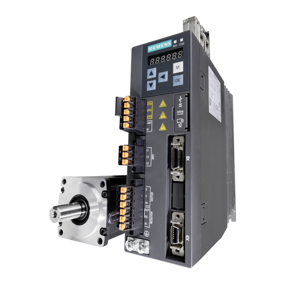
Siemens SIMOTICS S-1FL6 Manuals
Manuals and User Guides for Siemens SIMOTICS S-1FL6. We have 11 Siemens SIMOTICS S-1FL6 manuals available for free PDF download: Operating Instructions Manual, Compact Operating Instructions, Getting Started, Installation Manual
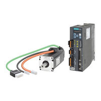
Siemens SIMOTICS S-1FL6 Operating Instructions Manual (432 pages)
Pulse Train, USS/Modbus Interface
Brand: Siemens
|
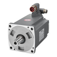
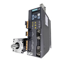
Category: Servo Drives
|
Size: 27 MB
Table of Contents
Advertisement

Siemens SIMOTICS S-1FL6 Operating Instructions Manual (364 pages)
Brand: Siemens
|
Category: Servo Drives
|
Size: 34 MB
Table of Contents

Siemens SIMOTICS S-1FL6 Operating Instructions Manual (362 pages)
PROFINET
Brand: Siemens
|
Category: Recording Equipment
|
Size: 16 MB
Table of Contents
Advertisement

Siemens SIMOTICS S-1FL6 Operating Instructions Manual (349 pages)
Brand: Siemens
|
Category: Controller
|
Size: 17 MB
Table of Contents
Siemens SIMOTICS S-1FL6 Operating Instructions Manual (330 pages)
Brand: Siemens
|
Category: Servo Drives
|
Size: 18 MB
Table of Contents

Siemens SIMOTICS S-1FL6 Operating Instructions Manual (320 pages)
Brand: Siemens
|
Category: Recording Equipment
|
Size: 16 MB
Table of Contents

Siemens SIMOTICS S-1FL6 Operating Instructions Manual (298 pages)
SINAMICS / SIMOTICS
Brand: Siemens
|
Category: Servo Drives
|
Size: 18 MB
Table of Contents

Siemens SIMOTICS S-1FL6 Getting Started (116 pages)
Pulse train, USS/Modbus interface
Brand: Siemens
|
Category: Recording Equipment
|
Size: 6 MB
Table of Contents
Siemens SIMOTICS S-1FL6 Compact Operating Instructions (119 pages)
PROFINET PN Interface
Brand: Siemens
|
Category: Servo Drives
|
Size: 5 MB
Table of Contents


Advertisement