Siemens SINAMICS V90 Operating Instructions Manual
Hide thumbs
Also See for SINAMICS V90:
- Operating instructions manual (432 pages) ,
- Operating manual (158 pages) ,
- Getting started (116 pages)
Table of Contents
Advertisement
Quick Links
SINAMICS/SIMOTICS
SINAMICS V90, SIMOTICS S-1FL6
Operating Instructions
PROFINET (PN) interface
04/2017
A5E37208830-003
___________________
Preface
Fundamental safety
___________________
instructions
___________________
General information
___________________
Mounting
___________________
Connecting
___________________
Commissioning
___________________
Basic operator panel (BOP)
___________________
Control functions
___________________
PROFINET communication
___________________
Safety integrated function
___________________
Tuning
___________________
Parameters
___________________
Diagnostics
___________________
Appendix
1
2
3
4
5
6
7
8
9
10
11
12
A
Advertisement
Table of Contents

Related Manuals for Siemens SINAMICS V90


Summary of Contents for Siemens SINAMICS V90
- Page 1 ___________________ Preface Fundamental safety ___________________ instructions ___________________ SINAMICS/SIMOTICS General information ___________________ Mounting SINAMICS V90, SIMOTICS S-1FL6 ___________________ Connecting ___________________ Commissioning Operating Instructions ___________________ Basic operator panel (BOP) ___________________ Control functions ___________________ PROFINET communication ___________________ Safety integrated function ___________________ Tuning ___________________...
- Page 2 Note the following: WARNING Siemens products may only be used for the applications described in the catalog and in the relevant technical documentation. If products and components from other manufacturers are used, these must be recommended or approved by Siemens. Proper transport, storage, installation, assembly, commissioning, operation and maintenance are required to ensure that the products operate safely and without any problems.
-
Page 3: Preface
SINAMICS V90 drives via the SINAMICS V- ASSISTANT engineering tool. Target group This manual provides information about the SINAMICS V90 PN servo system for planners, operators, mechanical engineers, electrical engineers, commissioning engineers, and service engineers. Technical support... - Page 4 This document contains recommendations relating to third-party products. Siemens accepts the fundamental suitability of these third-party products. You can use equivalent products from other manufacturers. Siemens does not accept any warranty for the properties of third-party products. SINAMICS V90, SIMOTICS S-1FL6 Operating Instructions, 04/2017, A5E37208830-003...
-
Page 5: Table Of Contents
Function list ..........................50 Technical data ......................... 51 2.6.1 Techincal data - servo drives ....................51 2.6.1.1 SINAMICS V90 PN 200 V variant ................... 51 2.6.1.2 SINAMICS V90 PN 400 V variant ................... 54 2.6.2 Technical data - servo motors ....................57 2.6.2.1... - Page 6 Adjusting an absolute encoder ..................... 146 Control functions ..........................147 General functions ......................... 147 7.1.1 Motor direction of rotation ....................147 7.1.2 Stopping method at servo OFF .................... 147 7.1.3 Travel to fixed stop ....................... 149 SINAMICS V90, SIMOTICS S-1FL6 Operating Instructions, 04/2017, A5E37208830-003...
- Page 7 POS_ZSW1 positioning status word ..................193 8.4.10 POS_ZSW2 positioning status word ..................194 Safety integrated function ........................195 Standards and regulations ....................195 9.1.1 General information ......................195 9.1.1.1 Aims ............................195 SINAMICS V90, SIMOTICS S-1FL6 Operating Instructions, 04/2017, A5E37208830-003...
- Page 8 Resonance suppression ...................... 228 10.7 Low frequency vibration suppression................... 231 Parameters ............................233 11.1 Overview ..........................233 11.2 Parameter list ........................235 Diagnostics ............................269 12.1 List of faults and alarms ....................... 274 SINAMICS V90, SIMOTICS S-1FL6 Operating Instructions, 04/2017, A5E37208830-003...
- Page 9 Assembly of cable connectors on the motor side ..............304 Motor selection ........................311 A.3.1 Selection procedure ......................311 A.3.2 Parameter description ......................312 A.3.3 Selection examples ....................... 314 Replacing fans ........................315 Index..............................317 SINAMICS V90, SIMOTICS S-1FL6 Operating Instructions, 04/2017, A5E37208830-003...
- Page 10 Table of contents SINAMICS V90, SIMOTICS S-1FL6 Operating Instructions, 04/2017, A5E37208830-003...
-
Page 11: Fundamental Safety Instructions
Touching live components can result in death or severe injury. • Only use power supplies that provide SELV (Safety Extra Low Voltage) or PELV- (Protective Extra Low Voltage) output voltages for all connections and terminals of the electronics modules. SINAMICS V90, SIMOTICS S-1FL6 Operating Instructions, 04/2017, A5E37208830-003... - Page 12 When opening plug connections in operation, arcs can result in severe injury or death. • Only open plug connections when the equipment is in a no-voltage state, unless it has been explicitly stated that they can be opened in operation. SINAMICS V90, SIMOTICS S-1FL6 Operating Instructions, 04/2017, A5E37208830-003...
- Page 13 People with pacemakers or implants are at particular risk in the immediate vicinity of this equipment. • If you have a heart pacemaker or implant, maintain a minimum distance of 2 m from electrical power equipment. SINAMICS V90, SIMOTICS S-1FL6 Operating Instructions, 04/2017, A5E37208830-003...
- Page 14 This can cause severe injury or even death. This can also result in increased downtime and reduced service lives for devices/systems. • Ensure compliance with the specified minimum clearance as ventilation clearance for the respective component. SINAMICS V90, SIMOTICS S-1FL6 Operating Instructions, 04/2017, A5E37208830-003...
- Page 15 Note Important safety notices for Safety Integrated functions If you want to use Safety Integrated functions, you must observe the safety notices in the Safety Integrated manuals. SINAMICS V90, SIMOTICS S-1FL6 Operating Instructions, 04/2017, A5E37208830-003...
- Page 16 • Operate the motor according to the relevant specifications. • Only operate the motors in conjunction with effective temperature monitoring. • Immediately switch off the motor if excessively high temperatures occur. SINAMICS V90, SIMOTICS S-1FL6 Operating Instructions, 04/2017, A5E37208830-003...
-
Page 17: Handling Electrostatic Sensitive Devices (Esd)
– Wearing ESD shoes or ESD grounding straps in ESD areas with conductive flooring • Only place electronic components, modules or devices on conductive surfaces (table with ESD surface, conductive ESD foam, ESD packaging, ESD transport container). SINAMICS V90, SIMOTICS S-1FL6 Operating Instructions, 04/2017, A5E37208830-003... -
Page 18: Industrial Security
Siemens’ products and solutions undergo continuous development to make them more secure. Siemens strongly recommends to apply product updates as soon as available and to always use the latest product versions. Use of product versions that are no longer supported, and failure to apply latest updates may increase customer’s exposure to cyber threats. -
Page 19: Residual Risks Of Power Drive Systems
6. Influence of network-connected communication systems, e.g. ripple-control transmitters or data communication via the network For more information about the residual risks of the drive system components, see the relevant sections in the technical user documentation. SINAMICS V90, SIMOTICS S-1FL6 Operating Instructions, 04/2017, A5E37208830-003... - Page 20 Fundamental safety instructions 1.4 Residual risks of power drive systems SINAMICS V90, SIMOTICS S-1FL6 Operating Instructions, 04/2017, A5E37208830-003...
-
Page 21: General Information
General information The SINAMICS V90 drives with the PROFINET interface (referred to as SINAMICS V90 PN) are available in two variants, 400 V variant and 200 V variant. The 200 V variant is available in three frame sizes: FSB, FSC, and FSD. Frame sizes B, and C are used on the single phase or three phase power network while frame size D is used on the three phase power network only. - Page 22 Information Guide English-Chinese bilingual version * You can obtain the connectors for SINAMICS V90 PN 400V servo drives of FSB and FSC from the connector kits for SINAMICS V90 PN 400V servo drives of FSAA or FSA. SINAMICS V90, SIMOTICS S-1FL6...
- Page 23 2.1 Deliverables Drive rating plate (example) ① ⑤ Drive name Article number ② ⑥ Power input MAC address ③ ⑦ Power output Product serial number ④ ⑧ Rated motor power Part number SINAMICS V90, SIMOTICS S-1FL6 Operating Instructions, 04/2017, A5E37208830-003...
- Page 24 General information 2.1 Deliverables Article number explanation (example) SINAMICS V90, SIMOTICS S-1FL6 Operating Instructions, 04/2017, A5E37208830-003...
- Page 25 General information 2.1 Deliverables Serial number explanation (example) SINAMICS V90, SIMOTICS S-1FL6 Operating Instructions, 04/2017, A5E37208830-003...
-
Page 26: Motor Components
❑❑1 1FL6092-1AC61- ❑ ❑❑1 1FL6094-1AC61- ❑ ❑❑1 1FL6096-1AC61- ❑ ❑❑1 Straight connectors with a fixed outlet direction Angular connectors with a flexible outlet direction User documentation SIMOTICS S-1FL6 Servo Motors Installation Guide SINAMICS V90, SIMOTICS S-1FL6 Operating Instructions, 04/2017, A5E37208830-003... - Page 27 Thermal class Motor ID ④ ⑩ ⑯ Rated torque Degree of protection Weight ⑤ ⑪ ⑰ Stall torque Motor operating mode Maximum speed ⑥ ⑫ ⑱ Rated voltage Stall current Rated speed SINAMICS V90, SIMOTICS S-1FL6 Operating Instructions, 04/2017, A5E37208830-003...
- Page 28 General information 2.1 Deliverables Article number explanation SINAMICS V90, SIMOTICS S-1FL6 Operating Instructions, 04/2017, A5E37208830-003...
-
Page 29: Device Combination
(10 m) (10 m) CK31-1CA0 BL02-1CA0 10-1CA0 (20 m) (20 m) (20 m) Incremental encoder TTL 2500 ppr Incremental encoder TTL 2500 ppr Absolute encoder single-turn 21-bit Absolute encoder single- turn 21-bit SINAMICS V90, SIMOTICS S-1FL6 Operating Instructions, 04/2017, A5E37208830-003... - Page 30 (20 m) 1AC61-0 0UF0 33.4 2000 ❑ ❑ FE17- 1AC61-0 0UF0 Incremental encoder TTL 2500 ppr Incremental encoder TTL 2500 ppr Absolute encoder 20-bit + 12-bit multi-turn Absolute encoder 20-bit + 12-bit multi-turn SINAMICS V90, SIMOTICS S-1FL6 Operating Instructions, 04/2017, A5E37208830-003...
- Page 31 12-bit multi-turn Note You can select a SINAMICS V90 PN servo drive for all the SIMOTICS S-1FL6 servo motors whose rated power values are equal to or smaller than that specified as matching with this servo drive in the table above.
-
Page 32: Product Overview
General information 2.3 Product overview Product overview SINAMICS V90 PN servo drives ● SINAMICS V90 PN 200V variant FSC and FSD SINAMICS V90, SIMOTICS S-1FL6 Operating Instructions, 04/2017, A5E37208830-003... - Page 33 General information 2.3 Product overview ● SINAMICS V90 PN 400V variant FSAA and FSA FSB and FSC SINAMICS V90, SIMOTICS S-1FL6 Operating Instructions, 04/2017, A5E37208830-003...
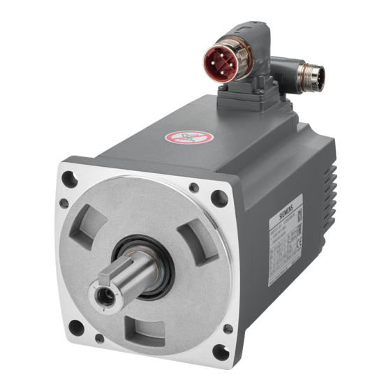
- Page 34 General information 2.3 Product overview SIMOTICS S-1FL6 servo motors ● Low inertia motors ● High inertia motors with straight connectors SINAMICS V90, SIMOTICS S-1FL6 Operating Instructions, 04/2017, A5E37208830-003...
- Page 35 General information 2.3 Product overview ● High inertia motors with angular connectors SINAMICS V90, SIMOTICS S-1FL6 Operating Instructions, 04/2017, A5E37208830-003...
-
Page 36: Accessories
1AF0 nector 10 m 2CT20- 1BA0 20 m 2CT20- 1CA0 Absolute 2DB20- Abso- 0DB12 encoder 1AD0 lute cable encoder 2DB20- con- 1AF0 nector 10 m 2DB20- 1BA0 20 m 2DB20- 1CA0 SINAMICS V90, SIMOTICS S-1FL6 Operating Instructions, 04/2017, A5E37208830-003... - Page 37 20 m 5CL11- 1CA0 Brake 5BL02- Brake 0LL51 cable 1AD0 con- nector 5BL02- 1AF0 7 m ** 5BL02- 1AH0 10 m 5BL02- 1BA0 15 m ** 5BL02- 1BF0 20 m 5BL02- 1CA0 SINAMICS V90, SIMOTICS S-1FL6 Operating Instructions, 04/2017, A5E37208830-003...
- Page 38 1AD0 of 0.4 kW to 1 kW: high inertia (with angu- con- lar connectors): nector 5CL02- 1AF0 5CL02- 1AH0 10 m 5CL02- 1BA0 15 m 5CL02- 1BF0 20 m 5CL02- 1CA0 SINAMICS V90, SIMOTICS S-1FL6 Operating Instructions, 04/2017, A5E37208830-003...
- Page 39 0SB14 Incre- 2CT12- Incre- 0SL13 er con- mental 1AD0 mental nector encoder encoder 2CT12- cable con- 1AF0 nector 2CT12- 1AH0 10 m 2CT12- 1BA0 15 m 2CT12- 1BF0 20 m 2CT12- 1CA0 SINAMICS V90, SIMOTICS S-1FL6 Operating Instructions, 04/2017, A5E37208830-003...
- Page 40 * The cables with a maximum length of 20 m are provided at delivery. You can also make your own cables with a maximum length of 30 m, which are not tested by Siemens. ** The cables with lengths of 7 m and 15 m are only supplied for high inertia motors.
- Page 41 National Electrical Code and any additional local codes. Refer to the table below for the selection of fuses, type-E combination motor controllers, and circuit breakers: SINAMICS V90 PN 200 V variant SINAMICS V90 PN Recommended fuse...
- Page 42 3RV 2011- (25 A) 4AA10 The above types for type-E combination motor controllers are listed in compliance with both CE and UL/cUL standards. SINAMICS V90 PN 400 V variant SINAMICS V90 PN Recommended fuse type Type-E combination motor controller Power...
- Page 43 • Suitable for Type 2 SPD application • Clamping shall be provided between phases and also between phase and ground Braking resistor The SINAMICS V90 PN has a built-in braking resistor. The table below shows the information of the built-in resistor: SINAMICS V90 PN Resistance (Ω)
- Page 44 189.6 Filter Siemens recommends you to use a line filter to protect the system from high frequency noise. The line filter restricts the conductive interference emitted from the SINAMICS V90 PN to the permissible values. The SINAMICS V90 PN drives with these external line filters have been tested in accordance with the emission requirements of the Category C2 environment.
- Page 45 Power supply Frame size 3-phase, 200 VAC to 6SL3203-0BE15-0VA0 240 VAC 6SL3203-0BE21-2VA0 3-phase, FSAA 6SL3203-0BE15-0VA0 380 VAC to 480 VAC 6SL3203-0BE21-2VA0 6SL3203-0BE22-0VA0 Outline dimensions (mm) Filter used on the single phase power network SINAMICS V90, SIMOTICS S-1FL6 Operating Instructions, 04/2017, A5E37208830-003...
- Page 46 50/60 Hz (-10% to +10%) Product standard IEC 61800-5-1 Power loss < 1 W < 3 W < 8 W Package size (H × W 543 × 318 × 351 × D) SINAMICS V90, SIMOTICS S-1FL6 Operating Instructions, 04/2017, A5E37208830-003...
- Page 47 18 A Noise frequency 0.15 (MHz) CM (dB) DM (dB) Rated current 20 A Noise frequency 0.15 (MHz) CM (dB) DM (dB) Connecting (example) Filter used on the single phase power network SINAMICS V90, SIMOTICS S-1FL6 Operating Instructions, 04/2017, A5E37208830-003...
- Page 48 6SL3210-5FB10- 24 to 22 2UF0 6SL3210-5FB10- 22 to 20 4UF1 6SL3210-5FB10- 18 to 16 8UF0 6SL3210-5FB11- Cross-tip 16 to 14 0UF1 screw) 6SL3210-5FB11- 14 to 12 5UF0 6SL3210-5FB12- 14 to 12 0UF0 SINAMICS V90, SIMOTICS S-1FL6 Operating Instructions, 04/2017, A5E37208830-003...
- Page 49 Optionally a micro SD card/SD card can be used to copy drive parameters or perform a firmware update. Micro SD card is used for 200 V variant servo drive and SD card is used for 400 V variant servo drive. Siemens recommends you to use the Siemens SD card (article number: 6SL3054-4AG00-2AA0).
-
Page 50: Function List
Control signals and status signals can be assigned to four EPOS, S (Page 99) programmable digital inputs and two digital outputs PROFINET communication Supports communication between the SINAMICS V90 PN EPOS, S (Page 177) servo drive and PLC with PROFINET communication proto- SINAMICS V-ASSISTANT... -
Page 51: Technical Data
General information 2.6 Technical data Technical data 2.6.1 Techincal data - servo drives 2.6.1.1 SINAMICS V90 PN 200 V variant General technical data Parameter Description Overload capability 300% Control system Servo control Dynamic brake Built-in Protective functions Earthing fault protection, output short-circuit protection... - Page 52 The V90 PN 200 V servo drive has an overvoltage threshold of 410 VDC and an undervoltage threshold of 150 VDC; the V90 PN 400 V servo drive has an overvoltage threshold of 820 VDC and an undervoltage threshold of 320 VDC. SINAMICS V90 PN does not support motor overtemperature protection. Motor overtemperature is calculated by I t and protected by the output current from the drive.
- Page 53 The values here are calculated at rated load. When SINAMICS V90 PN works with a motor with a brake, the voltage tolerance of 24 VDC power supply must be -10% to +10% to meet the voltage requirement of the brake.
-
Page 54: Sinamics V90 Pn 400 V Variant
General information 2.6 Technical data 2.6.1.2 SINAMICS V90 PN 400 V variant General technical data Parameter Description Overload capability 300% Control system Servo control Dynamic brake Built-in Protective functions Earthing fault protection, output short-circuit protection , overvolt- age/undervoltage protection t inverter,I... - Page 55 The V90 PN 200 V servo drive has an overvoltage threshold of 410 VDC and an undervoltage threshold of 150 VDC; the V90 PN 400 V servo drive has an overvoltage threshold of 820 VDC and an undervoltage threshold of 320 VDC. SINAMICS V90 PN does not support motor overtemperature protection. Motor overtemperature is calculated by I t and protected by the output current from the drive.
- Page 56 The values here are calculated at rated load. When SINAMICS V90 PN works with a motor with a brake, the voltage tolerance of 24 VDC power supply must be -10% to +10% to meet the voltage requirement of the brake.
-
Page 57: Technical Data - Servo Motors
Maximum torque [Nm] 0.48 0.96 1.91 3.82 9.54 14.3 19.1 Rated speed [rpm] 3000 Maximum speed [rpm] 5000 Rated frequency [Hz] Rated current [A] 10.6 11.6 Maximum current [A] 14.2 18.9 31.8 34.8 SINAMICS V90, SIMOTICS S-1FL6 Operating Instructions, 04/2017, A5E37208830-003... - Page 58 This lifetime is only for reference. When a motor keeps running at 80% rated value and the surrounding temperature is 30 °C, the encoder lifetime can be ensured. Note The data of rated torque, rated power, maximum torque, and armature resistance in the above table allows a tolerance of 10%. SINAMICS V90, SIMOTICS S-1FL6 Operating Instructions, 04/2017, A5E37208830-003...
- Page 59 General information 2.6 Technical data Torque-Speed characteristics SINAMICS V90, SIMOTICS S-1FL6 Operating Instructions, 04/2017, A5E37208830-003...
- Page 60 • The feature in short-term operating area varies with power supply voltages. • The continuous operating area becomes smaller and the voltage consumptions on the cables grow larger when the cables in the major loop exceed 20 m. Permissible radial and axial forces SINAMICS V90, SIMOTICS S-1FL6 Operating Instructions, 04/2017, A5E37208830-003...
-
Page 61: 1Fl6 Servo Motor - High Inertia
15.9 17.7 23.4 33.0 36.9 35.6 Moment of inertia [10 15.3/1 15.3 22.6 29.9 47.4 69.1 90.8 134.3 Moment of inertia (with 16.4/1 16.4 23.7 31.0 56.3 77.9 99.7 143.2 brake) [10 SINAMICS V90, SIMOTICS S-1FL6 Operating Instructions, 04/2017, A5E37208830-003... - Page 62 This lifetime is only for reference. When a motor keeps running at 80% rated value and the surrounding temperature is 30 °C, the encoder lifetime can be ensured. Note The data of rated torque, rated power, and maximum torque in the above table allows a tolerance of 10%. SINAMICS V90, SIMOTICS S-1FL6 Operating Instructions, 04/2017, A5E37208830-003...
- Page 63 General information 2.6 Technical data Torque-Speed characteristics SINAMICS V90, SIMOTICS S-1FL6 Operating Instructions, 04/2017, A5E37208830-003...
- Page 64 1FL604❑ and 1FL609❑ have a 5 mm of shaft sheltered in sleeves, and 1FL606❑ has an 8 mm of shaft in sleeves. Therefore, the distances to flange in the above three figures begin respectively from 5 mm, 8mm, and 5 mm. SINAMICS V90, SIMOTICS S-1FL6 Operating Instructions, 04/2017, A5E37208830-003...
-
Page 65: Power Derating
0.89 0.84 2000 1.00 0.94 0.90 0.86 0.82 2500 0.96 0.90 0.86 0.83 0.78 3000 0.92 0.86 0.82 0.79 0.75 3500 0.88 0.82 0.79 0.75 0.71 4000 0.82 0.77 0.74 0.71 0.67 SINAMICS V90, SIMOTICS S-1FL6 Operating Instructions, 04/2017, A5E37208830-003... -
Page 66: Technical Data - Cables
For high inertia motors of 0.4 kW to 1 kW 4 x 2.5: • For low inertia motors of 1.5 kW to 2 kW and high inertia motors of 1.5 kW to 7 kW SINAMICS V90, SIMOTICS S-1FL6 Operating Instructions, 04/2017, A5E37208830-003... -
Page 67: Address Of Ce-Authorized Manufacturer
Address of CE-authorized manufacturer The CE Declaration of Conformity is held on file available to the competent authorities at the following address: Siemens AG Digital Factory Motion Control Frauenauracher Straße 80 DE-91056 Erlangen Germany SINAMICS V90, SIMOTICS S-1FL6 Operating Instructions, 04/2017, A5E37208830-003... - Page 68 General information 2.6 Technical data SINAMICS V90, SIMOTICS S-1FL6 Operating Instructions, 04/2017, A5E37208830-003...
-
Page 69: Mounting
During operation and for a short time after switching-off the drive, the surfaces of the drive can reach a high temperature. Avoid coming into direct contact with the drive surface. For mounting conditions, see Techincal data - servo drives (Page 51). SINAMICS V90, SIMOTICS S-1FL6 Operating Instructions, 04/2017, A5E37208830-003... -
Page 70: Mounting Orientation And Clearance
10 mm. In this case, the minimum mounting clearance should not be less than 5 mm. • The surrounding temperature is 45 °C to 55 °C. In this case, the minimum mounting clearance should not be less than 20 mm. SINAMICS V90, SIMOTICS S-1FL6 Operating Instructions, 04/2017, A5E37208830-003... -
Page 71: Drill Patterns And Outline Dimensions
Mounting 3.1 Mounting the drive 3.1.2 Drill patterns and outline dimensions SINAMICS V90 PN 200V variant (unit: mm) SINAMICS V90, SIMOTICS S-1FL6 Operating Instructions, 04/2017, A5E37208830-003... - Page 72 Mounting 3.1 Mounting the drive SINAMICS V90 PN 400V variant (unit: mm) SINAMICS V90, SIMOTICS S-1FL6 Operating Instructions, 04/2017, A5E37208830-003...
- Page 73 Mounting 3.1 Mounting the drive SINAMICS V90, SIMOTICS S-1FL6 Operating Instructions, 04/2017, A5E37208830-003...
-
Page 74: Mounting The Drive
1 m. • The harmonic current value of SINAMICS V90 PN drive exceeds the class A limit of IEC 61000-3-2, but the SINAMICS V90 PN drive system installed within the Category C2 First Environment require supply authority acceptance for connection to the public low-voltage power supply network. -
Page 75: Mounting The Motor
Note When configuring the IM V3 type of construction, pay particular attention to the permissible axial force (weight force of the drive elements) and the necessary degree of protection. SINAMICS V90, SIMOTICS S-1FL6 Operating Instructions, 04/2017, A5E37208830-003... - Page 76 Rated torque 0.05 kW 0.16 Nm 38.5 0.1 kW 0.32 Nm 38.5 Shaft height 30 mm Rated power Rated torque 0.2 kW 0.64 Nm 39.5 132.5 0.4 kW 1.27 Nm 39.5 157.5 SINAMICS V90, SIMOTICS S-1FL6 Operating Instructions, 04/2017, A5E37208830-003...
- Page 77 0.75 kW 2.39 Nm 178.3 1.0 kW 3.18 Nm 158.8 198.1 Shaft height 50 mm Rated power Rated torque a 1.5 kW 4.78 Nm 143.5 177.5 2.0 kW 6.37 Nm 167.5 201.5 SINAMICS V90, SIMOTICS S-1FL6 Operating Instructions, 04/2017, A5E37208830-003...
- Page 78 Shaft height 45 mm, with the incremental encoder and straight connectors Shaft height 45 mm, with the incremental encoder and angular connectors Rated power Rated torque 0.4 kW 1.27 Nm 154.5 169.5 61.5 0.75 kW 2.39 Nm 201.5 216.5 SINAMICS V90, SIMOTICS S-1FL6 Operating Instructions, 04/2017, A5E37208830-003...
- Page 79 Shaft height 45 mm, with the absolute encoder and straight connectors Shaft height 45 mm, with the absolute encoder and angular connectors Rated power Rated torque 0.4 kW 1.27 Nm 203.5 61.5 0.75 kW 2.39 Nm 250.5 SINAMICS V90, SIMOTICS S-1FL6 Operating Instructions, 04/2017, A5E37208830-003...
- Page 80 268.5 2.0 kW 9.55 Nm 301.5 The former value indicates the dimension for high inertia motors with straight connectors; the latter value indicates the dimension for high inertia motors with angular connectors. SINAMICS V90, SIMOTICS S-1FL6 Operating Instructions, 04/2017, A5E37208830-003...
- Page 81 271.5 2.0 kW 9.55 Nm 304.5 The former value indicates the dimension for high inertia motors with straight connectors; the latter value indicates the dimension for high inertia motors with angular connectors. SINAMICS V90, SIMOTICS S-1FL6 Operating Instructions, 04/2017, A5E37208830-003...
- Page 82 Shaft height 90 mm, with the incremental encoder and angular connectors Rated power Rated torque 2.5 kW 11.9 Nm 189.5 210.5 98.5 3.5 kW 16.7 Nm 211.5 236.5 5.0 kW 23.9 Nm 237.5 262.5 7.0 kW 33.4 Nm 289.5 314.5 SINAMICS V90, SIMOTICS S-1FL6 Operating Instructions, 04/2017, A5E37208830-003...
- Page 83 Shaft height 90 mm, with the absolute encoder and angular connectors Rated power Rated torque 2.5 kW 11.9 Nm 98.5 3.5 kW 16.7 Nm 5.0 kW 23.9 Nm 7.0 kW 33.4 Nm SINAMICS V90, SIMOTICS S-1FL6 Operating Instructions, 04/2017, A5E37208830-003...
-
Page 84: Mounting The Motor
The 1FL609❑ motor (90 mm shaft height) has two M8 screw holes for screwing in two eyebolts. Lift the 1FL609❑ motor only at the eyebolts. Eyebolts that have been screwed in must be either tightened or removed after mounting. SINAMICS V90, SIMOTICS S-1FL6 Operating Instructions, 04/2017, A5E37208830-003... -
Page 85: Motor Heating Conditions
Make sure you use a suitable flange according to Siemens recommended flange sizes. Note The actual temperature rise depends on how the flange (motor mounting section) is fixed on the installation surface, what material is used for the motor mounting section, and motor speed. - Page 86 Mounting 3.2 Mounting the motor SINAMICS V90, SIMOTICS S-1FL6 Operating Instructions, 04/2017, A5E37208830-003...
-
Page 87: Connecting
Connecting System connection The SINAMICS V90 PN servo drive is integrated with digital input/output interface and PROFINET communication port. It can be connected either to a Siemens controllers like S7- 1200 or S7-1500. The following illustrations show the examples of the SINAMICS V90 PN servo system connection. - Page 88 When the equipment is working, hazardous touch current can be present at the PE connectors; if touched, this can result in death or severe personal injury. • Do not touch the PE connector during operation or within a certain period since power disconnection. SINAMICS V90, SIMOTICS S-1FL6 Operating Instructions, 04/2017, A5E37208830-003...
- Page 89 In order to meet EMC requirements, all cables must be shielded cables. The cable shields of shielded twisted-pair cables should be connected to the shielding plate or the hose clamp of the servo drive. SINAMICS V90, SIMOTICS S-1FL6 Operating Instructions, 04/2017, A5E37208830-003...
- Page 90 For low inertia motors of shaft heights 20 mm, 30 mm and 40 mm, the encoder cable connectors may only be accessible to electrically skilled personnel. Note The mini-USB interface of the SINAMICS V90 PN is used for fast commissioning and diagnostics with SINAMICS V-ASSISTANT installed in the PC. Do not use it for long monitoring.
- Page 91 • It is not permissible that the short-circuit current exceeds the SCCR or the I of the inverter and the disconnecting capacity of the protective equipment. SINAMICS V90, SIMOTICS S-1FL6 Operating Instructions, 04/2017, A5E37208830-003...
- Page 92 Low inertia motors with a shaft height of 50 mm and high inertia motors with straight connectors Note Rotating the connectors You can rotate all the three motor-side connectors only within 360°. SINAMICS V90, SIMOTICS S-1FL6 Operating Instructions, 04/2017, A5E37208830-003...
- Page 93 For an absolute encoder cable on a high inertia motor with angular connectors, adjust its direction just the same as you adjust the cable directions on a high inertia motor with straight connectors mentioned above. SINAMICS V90, SIMOTICS S-1FL6 Operating Instructions, 04/2017, A5E37208830-003...
-
Page 94: Main Circuit Wiring
The procedure of assembling a line supply cable terminal is the same as that for a power cable terminal on the drive side. For more information, see Section "Assembly of cable terminals on the drive side (Page 301)". SINAMICS V90, SIMOTICS S-1FL6 Operating Instructions, 04/2017, A5E37208830-003... - Page 95 The FSB and FSC servo drives are equipped with barrier terminals for line supply connection. You can fix the line supply cable on the servo drives by using the M4 screws with a tightening torque of 2.25 Nm (19.91 lb.in). SINAMICS V90, SIMOTICS S-1FL6 Operating Instructions, 04/2017, A5E37208830-003...
-
Page 96: Motor Power - U, V, W
High inertia motor, shaft height: 45 mm, 60 mm, and 90 mm Straight connectors: Black Phase U Black Phase V Black Phase W Yellow-green Protective earthing Angular connectors (for high inertia motors only): SINAMICS V90, SIMOTICS S-1FL6 Operating Instructions, 04/2017, A5E37208830-003... - Page 97 • Make sure you first fix the motor power connector on the drive, and then attach the cable to the connector. 200 V variant ● For FSB SINAMICS V90, SIMOTICS S-1FL6 Operating Instructions, 04/2017, A5E37208830-003...
- Page 98 The FSB and FSC servo drives are equipped with barrier terminals for motor power connection. You can fix the motor power cable on the servo drives by using the M4 screws with a tightening torque of 2.25 Nm (19.91 lb.in). SINAMICS V90, SIMOTICS S-1FL6 Operating Instructions, 04/2017, A5E37208830-003...
-
Page 99: Control/Status Interface - X8
* The pins are used to connect the brake control signals for 200 V variant drive only. 4.3.1 Digital inputs/outputs (DIs/Dos) SINAMICS V90 PN supports free assignment of signals to the following digital input and output terminals depending on the control mode selected: DI1 to DI4 -- Assignable with parameters p29301 to p29304... -
Page 100: Dis
DO1 and DO2 by setting the bit 0 and bit 1 of parameter p0748. 4.3.1.1 You can assign a maximum of seven internal digital input signals to the SINAMICS V90 PN servo drive. For detailed information about these signals, see the table below:... -
Page 101: Dos
NPN wiring PNP wiring 4.3.1.2 You can assign a maximum of 10 internal digital output signals to the SINAMICS V90 PN servo drive. For detailed information about these signals, see the table below: Name Descriptions Servo ready 1: the drive is ready. - Page 102 Note: STO_EP is only a status signal for STO input terminals but not a safe DO for the Safety Integrated function. Wiring The digital outputs support both PNP and NPN types of wirings. You can find detailed information from the following diagrams: NPN wiring PNP wiring SINAMICS V90, SIMOTICS S-1FL6 Operating Instructions, 04/2017, A5E37208830-003...
-
Page 103: Standard Application Wiring (Factory Setting)
Connecting 4.3 Control/status interface - X8 4.3.2 Standard application wiring (factory setting) Example 1 SINAMICS V90, SIMOTICS S-1FL6 Operating Instructions, 04/2017, A5E37208830-003... - Page 104 Digital inputs, supporting both PNP and NPN types. The pins are used to connect the brake control signals for 200 V variant drive only. Re- fer to section "Motor holding brake (Page 113)" for the detailed connections. SINAMICS V90, SIMOTICS S-1FL6 Operating Instructions, 04/2017, A5E37208830-003...
-
Page 105: Connection Example With Plcs
Connecting 4.3 Control/status interface - X8 4.3.3 Connection example with PLCs 4.3.3.1 SIMATICS S7-1200 SINAMICS V90, SIMOTICS S-1FL6 Operating Instructions, 04/2017, A5E37208830-003... -
Page 106: Simatics S7-1500
Connecting 4.3 Control/status interface - X8 4.3.3.2 SIMATICS S7-1500 SINAMICS V90, SIMOTICS S-1FL6 Operating Instructions, 04/2017, A5E37208830-003... -
Page 107: Power Supply/Sto
2). If you do not need to use it any more, you must reinsert the short-circuit stick; otherwise, the motor will not run. For detailed information about the STO function, refer to "Safety Integrated basic function (Page 211)". SINAMICS V90, SIMOTICS S-1FL6 Operating Instructions, 04/2017, A5E37208830-003... -
Page 108: Encoder Interface - X9
(Page 301)". Plugging the 24 V power supply and STO cables Encoder interface - X9 The SINAMICS V90 PN 200V variant servo drive supports two kinds of encoders: ● Incremental encoder TTL 2500 ppr ● Absolute encoder single-turn 21-bit The SINAMICS V90 PN 400V variant servo drive supports two kinds of encoders: ●... - Page 109 Encoder R phase negative signal Encoder B phase negative signal Encoder B phase positive signal Encoder A phase negative signal Encoder A phase positive signal Screw type: UNC 4-40 (plug-in terminal block) Tightening torque: 0.4 Nm SINAMICS V90, SIMOTICS S-1FL6 Operating Instructions, 04/2017, A5E37208830-003...
- Page 110 Phase A- Clock_N Inverted clock Angular connect- Phase B+ Data_P Data ors (for high inertia Phase B- Clock_P Clock motors only): Phase R+ n. c. Not connected Phase R- Data_N Inverted data SINAMICS V90, SIMOTICS S-1FL6 Operating Instructions, 04/2017, A5E37208830-003...
- Page 111 Wiring Low inertia motor, shaft height: 20 mm, 30 mm and 40 mm Low inertia motor, shaft height: 50 mm High inertia motor, shaft height: 45 mm, 65 mm, and 90 mm SINAMICS V90, SIMOTICS S-1FL6 Operating Instructions, 04/2017, A5E37208830-003...
-
Page 112: External Braking Resistor - Dcp, R1
External braking resistor - DCP, R1 The SINAMICS V90 PN has been designed with an internal braking resistor to absorb regenerative energy from the motor. When the internal braking resistor cannot meet the braking requirements (e.g. -
Page 113: Motor Holding Brake
Input voltage tolerance: 24 V ± 10% Brake connector - motor side Illustration Pin No. Signal Description Low inertia motor, shaft height: 20 mm, 30 mm and 40 mm Brake+ Phase Brake+ Brake- Phase Brake- SINAMICS V90, SIMOTICS S-1FL6 Operating Instructions, 04/2017, A5E37208830-003... - Page 114 Low level (0) 24 V Closed Can run DO signal Signal type Signal name Setting Description ON = high level Motor holding brake is closed. OFF = low level Motor holding brake is released. SINAMICS V90, SIMOTICS S-1FL6 Operating Instructions, 04/2017, A5E37208830-003...
- Page 115 Wiring for the 200 V variant servo drive The following diagrams show the examples when the brake is controlled through the motor holding brake signal (Brake) of the 200 V variant servo drive. Example 1: SINAMICS V90, SIMOTICS S-1FL6 Operating Instructions, 04/2017, A5E37208830-003...
- Page 116 All the following data on a varistor is provided based on the low inertia motors with a rated power of 2 kW; however the data is also applicable to the low inertia motors of other power ranges. SINAMICS V90, SIMOTICS S-1FL6 Operating Instructions, 04/2017, A5E37208830-003...
- Page 117 Relay (R) used for the power supply of the brake Siemens recommends you to select a Siemens relay (article number: 3RQ3018-2AB00). You can find more information about Siemens relays from Chapter 05 of Catalog IC 10 - SIRIUS 2016 at the following Web site: Siemens relays (http://w3app.siemens.com/mcms/infocenter/content/en/Pages/order_form.aspx?nodeKey=k...
- Page 118 = motor brake opening time + relay opening time p1217 = motor brake closing time + relay closing time SINAMICS V90, SIMOTICS S-1FL6 Operating Instructions, 04/2017, A5E37208830-003...
- Page 119 The start of the closing time for the brake depends on the expiration of the shorter of p1227 (zero speed detection monitoring time) and p1228 (pulse suppression delay time). SINAMICS V90, SIMOTICS S-1FL6 Operating Instructions, 04/2017, A5E37208830-003...
-
Page 120: Profinet Interface - X150
LED. This allows the following status information about the respective PROFINET port to be displayed: Name Color Status Meaning Link Green Transfer rate 100 Mbit/s No or faulty connection Activity Orange Data exchange No data exchange SINAMICS V90, SIMOTICS S-1FL6 Operating Instructions, 04/2017, A5E37208830-003... - Page 121 Note When connecting the ports P1 and P2, you need to make sure that the physical input and output connections are the same with the connections in the topology. SINAMICS V90, SIMOTICS S-1FL6 Operating Instructions, 04/2017, A5E37208830-003...
- Page 122 Connecting 4.8 PROFINET interface - X150 SINAMICS V90, SIMOTICS S-1FL6 Operating Instructions, 04/2017, A5E37208830-003...
-
Page 123: Commissioning
Before starting up the drive with a micro SD card/SD card, check whether the micro SD card/SD card contains user setting data. Otherwise, the existing data on the drive may be overwritten. SINAMICS V90, SIMOTICS S-1FL6 Operating Instructions, 04/2017, A5E37208830-003... -
Page 124: Commissioning In Jog Mode
SINAMICS V-ASSISTANT is a software tool that can be installed on a PC and runs on the Windows operating system. It communicates with the SINAMICS V90 PN servo drive with a USB cable (To ensure the stability of online commissioning, Siemens recommends you to use a shielded USB cable of no longer than 3 m with ferrite cores on both ends.). - Page 125 Save parameters with the BOP. For detailed information about the parameter saving with the BOP, refer to "Saving parameters (RAM to ROM) (Page 142)". Switch on the main line supply. SINAMICS V90, SIMOTICS S-1FL6 Operating Instructions, 04/2017, A5E37208830-003...
-
Page 126: Commissioning In Basic Positioner Control Mode (Epos)
Set the mechanical gear ratio with parameters p29247: LU per load revolution • p29247, p29248 and p29249. p29248: load revolutions • p29249: motor revolutions • Refer to "Setting the mechanical system (Page 151)". SINAMICS V90, SIMOTICS S-1FL6 Operating Instructions, 04/2017, A5E37208830-003... -
Page 127: Commissioning In Speed Control Mode (S)
The device name must be unique within the PROFINET p8920. network. Active the IP configuration and device name with pa- rameter p8925. Set the torque limitation and speed limitation. Refer to "Torque limit (Page 173)" and "Speed limit (Page 172)". SINAMICS V90, SIMOTICS S-1FL6 Operating Instructions, 04/2017, A5E37208830-003... - Page 128 Send and receive the process data (PZD) with TIA The actual speed of the servo motor can be viewed from Portal. the BOP operating display. The default display is the actual speed. Refer to "Actual status display (Page 136)". SINAMICS V90, SIMOTICS S-1FL6 Operating Instructions, 04/2017, A5E37208830-003...
-
Page 129: Basic Operator Panel (Bop)
Basic operator panel (BOP) BOP overview Overview The SINAMICS V90 PN servo drive is designed with a Basic Operator Panel (BOP) on the front panel of the servo drive: You can use the BOP for the following operations: ● Standalone commissioning ●... -
Page 130: Led Status Indicators
PROFINET communication is working with RT Flash at 2 Hz Micro SD card/SD card operating (read or write) Continuously lit Communication error (always put the PROFINET communica- tion error as the first consideration) SINAMICS V90, SIMOTICS S-1FL6 Operating Instructions, 04/2017, A5E37208830-003... -
Page 131: Bop Display
1. xxx.xxx Negative parameter value xxx.xx<> Current display can be moved to left or right xxxx.xx> Current display can be moved to right xxxx.xx< Current display can be moved to left SINAMICS V90, SIMOTICS S-1FL6 Operating Instructions, 04/2017, A5E37208830-003... - Page 132 The zero position has been set Refer to "Adjusting an absolute encoder (Page 146)". r xxx Actual speed (positive direction) r -xxx Actual speed (negative direction) T x.x Actual torque (positive direction) SINAMICS V90, SIMOTICS S-1FL6 Operating Instructions, 04/2017, A5E37208830-003...
- Page 133 The communication between the commissioning tool SINAMICS V- ASSISTANT and the servo drive is established. In this case, the BOP is protected from any operations except clearing alarms and ac- knowledging faults. SINAMICS V90, SIMOTICS S-1FL6 Operating Instructions, 04/2017, A5E37208830-003...
-
Page 134: Control Buttons
Moves current display to the left page when is displayed at the upper right corner, for example Moves current display to the right page when is displayed at the lower right corner, for example SINAMICS V90, SIMOTICS S-1FL6 Operating Instructions, 04/2017, A5E37208830-003... -
Page 135: Parameter Structure
Basic operator panel (BOP) 6.2 Parameter structure Parameter structure The overall parameter structure of SINAMICS V90 PN BOP is designed as follows: Note There is no ABS menu function for a servo motor with an incremental encoder. The ABS menu function is only available for a servo motor with an absolute encoder. -
Page 136: Actual Status Display
– P COM: communication – P EPOS: basic positioner – P ALL: all parameters ● Read-only parameters: All r parameters under the "Data" menu are read-only parameters. You can only read values of these parameters. SINAMICS V90, SIMOTICS S-1FL6 Operating Instructions, 04/2017, A5E37208830-003... -
Page 137: Editing Parameters
All parameters that do not have indices are parameters without index. 6.4.1 Editing parameters You can edit a parameter value in two methods: ● Method 1: change the value directly with the UP or DOWN button SINAMICS V90, SIMOTICS S-1FL6 Operating Instructions, 04/2017, A5E37208830-003... - Page 138 ● Method 2: move the cursor to a digit with the SHIFT button, then change the digit value with the UP or DOWN button Note Parameters p1414 and p1656 cannot be changed using the SHIFT button. SINAMICS V90, SIMOTICS S-1FL6 Operating Instructions, 04/2017, A5E37208830-003...
-
Page 139: Viewing Parameters
If you do not know which group that a parameter belongs to, you can search for in the "P ALL" menu. Note Invalid parameter number If the input parameter number is unavailable, the nearest parameter number to the input value is displayed. SINAMICS V90, SIMOTICS S-1FL6 Operating Instructions, 04/2017, A5E37208830-003... -
Page 140: Auxiliary Functions
Adjust absolute encoder NOTE: This function is available only when the servo motor with an absolute encoder is connected. ④ Copy parameter set from a drive to a mi- cro SD card/SD card SINAMICS V90, SIMOTICS S-1FL6 Operating Instructions, 04/2017, A5E37208830-003... -
Page 141: Jog
To run the connected motor with the JOG function and view the JOG torque, proceed as follows: JOG in torque (example) NOTICE Exit the JOG mode after completing JOG run. The servo motor cannot run if the servo drive is in the JOG mode. SINAMICS V90, SIMOTICS S-1FL6 Operating Instructions, 04/2017, A5E37208830-003... -
Page 142: Saving Parameters (Ram To Rom)
• If a micro SD card/SD card has been inserted, the parameter set will be saved onto the micro SD card/SD card simultaneously. • All signal functions become inactive during the saving process. Use the signal functions afterwards. Reference Editing parameters (Page 137) SINAMICS V90, SIMOTICS S-1FL6 Operating Instructions, 04/2017, A5E37208830-003... -
Page 143: Setting Parameters To Default
Saving parameters (RAM to ROM) (Page 142) 6.5.4 Transferring data (drive to SD) You can save the parameter set from the drive ROM to a micro SD card/SD card with the BOP. To do this, proceed as follows: SINAMICS V90, SIMOTICS S-1FL6 Operating Instructions, 04/2017, A5E37208830-003... -
Page 144: Transferring Data (Sd To Drive)
Do not plug or unplug the micro SD card/SD card during transferring; otherwise, the transferring operation will fail. Note Write protection function is not supported by SINAMICS V90 PN. Data in the micro SD card/SD card will be overwritten even if the write protection function of the micro SD card/SD card is enabled. -
Page 145: Updating Firmware
Note Update the firmware by restarting the drive. After inserting the micro SD card/SD card with proper firmware files, you can also update the firmware by restarting the drive. SINAMICS V90, SIMOTICS S-1FL6 Operating Instructions, 04/2017, A5E37208830-003... -
Page 146: Adjusting An Absolute Encoder
With the BOP function menu "ABS", you can set the current position of an absolute encoder to the zero position. To do this, proceed as follows: Note Save parameter The position value is set in parameter p2525. You must save the parameters after setting the zero position. SINAMICS V90, SIMOTICS S-1FL6 Operating Instructions, 04/2017, A5E37208830-003... -
Page 147: Control Functions
● Ramp-down (OFF1) ● Coast-down (OFF2) ● Emergency stop (OFF3) Ramp-down (OFF1) and coast-down (OFF2) The ramp-down and coast-down can be configured with the PROFINET control words STW1.0 and STW1.1: SINAMICS V90, SIMOTICS S-1FL6 Operating Instructions, 04/2017, A5E37208830-003... - Page 148 Servo motor is ready to run. Emergency stop. For detailed information about the PROFINET control word and the digital input signal EMGS, refer to Section "Control word definition" and "Digital inputs/outputs (DIs/Dos) (Page 99)". SINAMICS V90, SIMOTICS S-1FL6 Operating Instructions, 04/2017, A5E37208830-003...
-
Page 149: Travel To Fixed Stop
The preset torque limit is effective from the start, i.e. travel to fixed stop also occurs with a SINAMICS V90, SIMOTICS S-1FL6 Operating Instructions, 04/2017, A5E37208830-003... - Page 150 EPOS traversing block, task parameter • p2622[0...15] EPOS fixed stop maximum following error • p2634 EPOS fixed stop monitoring window • p2635 For more information about the parameters above, see Section "Parameter list (Page 235)". SINAMICS V90, SIMOTICS S-1FL6 Operating Instructions, 04/2017, A5E37208830-003...
-
Page 151: Basic Positioner (Epos)
N times accordingly. Otherwise, the fault F7450 or F7452 occurs. Relevant parameters Parameter Range Factory setting Unit Description p29247 1 to 2147483647 10000 LU per load revolution p29248 1 to 1048576 Load revolutions p29249 1 to 1048576 Motor revolutions SINAMICS V90, SIMOTICS S-1FL6 Operating Instructions, 04/2017, A5E37208830-003... -
Page 152: Configuring The Linear/Modular Axis
You can choose to use a linear axis or a modular axis depending on your actual application. The linear axis has a restricted traversing range, which is the factory setting of the SINAMICS V90 PN servo drive. The modular axis has an unrestricted traversing range. The value range of the position repeats itself after a value is specified in p29245. -
Page 153: Backlash Compensation
Set signal source for start direction of searching cam: 0: start in positive direction • 1: start in negative direction • When telegram 111 is used, the value of p2604 is assigned by control word POS_STW2.9. SINAMICS V90, SIMOTICS S-1FL6 Operating Instructions, 04/2017, A5E37208830-003... -
Page 154: Over-Travel
CCWL X8-b (b = 1 to Falling edge The servo motor has travelled to the 4; b ≠ a) (1→0) counter-clockwise travel limit and has an emergency stop after that. SINAMICS V90, SIMOTICS S-1FL6 Operating Instructions, 04/2017, A5E37208830-003... -
Page 155: Software Position Limit
-2147482648 Negative software position limit switch 2147482647 p2581 -2147482648 to 2147482648 Positive software position limit switch 2147482647 p2582 0 to 1 Activation of software limit switch: 0: deactivate • 1: activate • SINAMICS V90, SIMOTICS S-1FL6 Operating Instructions, 04/2017, A5E37208830-003... -
Page 156: Speed Limit
When p29240 = 1 or 2, the referencing process can only be implemented before you use the "ABS" function. Once the "ABS" function is implemented, the two referencing modes are not available any more. SINAMICS V90, SIMOTICS S-1FL6 Operating Instructions, 04/2017, A5E37208830-003... - Page 157 The current position is set to zero at a rising edge of the signal REF and the servo drive is referenced: CAUTION The referencing point may not be fixed during referencing. The servo motor must be in "servo on" state so that the referencing point is fixed during referencing. SINAMICS V90, SIMOTICS S-1FL6 Operating Instructions, 04/2017, A5E37208830-003...
- Page 158 When the servo motor reaches the reference point (p2599), the signal REFOK is output. Set STW1.11 to 0 and the referencing finishes successfully. The whole process is shown in the diagram below: SINAMICS V90, SIMOTICS S-1FL6 Operating Instructions, 04/2017, A5E37208830-003...
- Page 159 When the servo motor reaches the reference point (p2599), the signal REFOK is output. Set control word STW1.11 to 0 and the referencing finishes successfully. SINAMICS V90, SIMOTICS S-1FL6 Operating Instructions, 04/2017, A5E37208830-003...
- Page 160 1 to 40000000 1000 Speed for searching reference point LU/min 2. Set STW1.11 (0→1) to start referencing. Note During the referencing, if STW1.11 is set to 0, the referencing stops. SINAMICS V90, SIMOTICS S-1FL6 Operating Instructions, 04/2017, A5E37208830-003...
-
Page 161: Traversing Blocks
Activating a traversing task When telegrams 7, 9, 110, and 111 are used, activate a traversing task with the PROFINET control word STW1.6: Control word Setting Description STW1.6 Traversing task activation. Traversing task deactivation. SINAMICS V90, SIMOTICS S-1FL6 Operating Instructions, 04/2017, A5E37208830-003... - Page 162 0101, CONTINUE_EXTERNAL_ALARM: This is the same as CONTINUE_EXTERNAL_WAIT, except that alarm A07463 "External traversing block change in traversing block x not requested" is output when SINAMICS V90, SIMOTICS S-1FL6 Operating Instructions, 04/2017, A5E37208830-003...
- Page 163 The FIXED STOP task triggers a traversing movement with reduced torque to fixed stop. The following parameters are relevant: ● p2616[x] Block number ● p2617[x] Position ● p2618[x] Velocity ● p2619[x] Acceleration override ● p2620[x] Deceleration override SINAMICS V90, SIMOTICS S-1FL6 Operating Instructions, 04/2017, A5E37208830-003...
- Page 164 The following parameters are relevant: ● p2622[x] Task parameter = delay time in milliseconds ≥ 0 ms, but is rounded-off to a multiple of numeral 8 ● p2623[x] Task mode SINAMICS V90, SIMOTICS S-1FL6 Operating Instructions, 04/2017, A5E37208830-003...
- Page 165 Intermediate stop. Overview of important parameters EPOS traversing block, position • p2617[0...15] EPOS traversing block, velocity • p2618[0...15] EPOS traversing block, acceleration override • p2619[0...15] EPOS traversing block, deceleration override • p2620[0...15] SINAMICS V90, SIMOTICS S-1FL6 Operating Instructions, 04/2017, A5E37208830-003...
-
Page 166: Direct Setpoint Input (Mdi)
When telegram 111 is used, select a working mode with the PROFINET control word POS_STW1.14: Control word Setting Description POS_STW1.14 Signal setting-up selected. Signal positioning selected. Telegrams 7, 9, and 110 can only work in signal positioning mode. SINAMICS V90, SIMOTICS S-1FL6 Operating Instructions, 04/2017, A5E37208830-003... - Page 167 When telegram 7 is used, select an absolute positioning direction with the following parameter: Parameter Setting Description p29230 0 (default) Absolute positioning through the shortest distance. Absolute positioning/MDI direction selection, positive. Absolute positioning/MDI direction selection, negative. SINAMICS V90, SIMOTICS S-1FL6 Operating Instructions, 04/2017, A5E37208830-003...
- Page 168 ● Deceleration override (MDI_DEC): 4000 hex = 100% When telegram 7 is used, set MDI setpoints with the following parameters: ● Position setpoint (p2690) ● Velocity setpoint (p2691) ● Acceleration override (p2692) ● Deceleration override (p2693) SINAMICS V90, SIMOTICS S-1FL6 Operating Instructions, 04/2017, A5E37208830-003...
-
Page 169: Ejog
When telegrams 7, 9, 110, and 111 are used, select a jogging channel with the PROFINET control words STW1.8 and STW1.9: Control word Setting Description STW1.8 No jogging channel activated. STW1.9 Jog 1 signal source rising edge activated. Jog 2 signal source rising edge activated. Reserved. SINAMICS V90, SIMOTICS S-1FL6 Operating Instructions, 04/2017, A5E37208830-003... - Page 170 EPOS jog 2 setpoint velocity • p2586 EPOS jog 1 travel distance • p2587 EPOS jog 2 travel distance • p2588 For more information about the parameters above, see Section "Parameter list (Page 235)". SINAMICS V90, SIMOTICS S-1FL6 Operating Instructions, 04/2017, A5E37208830-003...
-
Page 171: Position Tracking
The following points can be set by configuring this parameter: Parameter Description p29243 0: deactivate position tracking • 1: activate position tracking • Note Be sure to perform the "ABS" function again after you set p29243 to 1. SINAMICS V90, SIMOTICS S-1FL6 Operating Instructions, 04/2017, A5E37208830-003... -
Page 172: Speed Control (S)
(p2162) or the negative speed limit - hysteresis speed (p2162). Go to "List of faults and alarms (Page 274)" for information about the acknowledgment of this fault. Refer to "DIs (Page 100)" for more information about the digital input signal SLIM. SINAMICS V90, SIMOTICS S-1FL6 Operating Instructions, 04/2017, A5E37208830-003... -
Page 173: Torque Limit
Note You can switch between the two sources and modify their values when the servo drive is running. Refer to "DIs (Page 100)" for more information about the digital input signal TLIM. SINAMICS V90, SIMOTICS S-1FL6 Operating Instructions, 04/2017, A5E37208830-003... - Page 174 The following diagram shows how the internal torque limit functions: Torque limit reached (TLR) When the generated torque has nearly (internal hysteresis) reached the value of the positive torque limit or negative torque limit, the signal TLR is output. SINAMICS V90, SIMOTICS S-1FL6 Operating Instructions, 04/2017, A5E37208830-003...
-
Page 175: Ramp-Function Generator
● the acceleration (p1120) and deceleration (p1121) ramps ● the initial (p1130) and final (p1131) rounding-off times You can see the properties of the S-curve ramp-function generator from the diagram below: SINAMICS V90, SIMOTICS S-1FL6 Operating Instructions, 04/2017, A5E37208830-003... - Page 176 0 to 999999 Ramp-function generator ramp-up time p1121 0 to 999999 Ramp-function generator ramp-down time p1130 0 to 30 Ramp-function generator initial rounding-off time p1131 0 to 30 Ramp-function generator final rounding-off time SINAMICS V90, SIMOTICS S-1FL6 Operating Instructions, 04/2017, A5E37208830-003...
-
Page 177: Profinet Communication
100 ms. Supported telegrams SINAMICS V90 PN supports standard telegrams and Siemens telegrams for speed control mode and basic positioner control mode. You can select the desired telegram with parameter p0922. See the following table for details. - Page 178 = 111 One PZD = one word Standard telegram 5 and Siemens telegram 105 can only be used when the V90 PN connects to the SIMATICS S7-1500 and the TIA Portal version is V14 or higher. Telegrams used for speed control mode...
-
Page 179: I/O Data Signals
Send word ZSW2 Status word 2 Send word NSOLL_A Speed setpoint A (16 bit) Receive word 4000 hex ≙ p2000 NSOLL_B Speed setpoint B (32 bit) Receive word 40000000 hex ≙ p2000 SINAMICS V90, SIMOTICS S-1FL6 Operating Instructions, 04/2017, A5E37208830-003... - Page 180 1: Actual torque (0x4000 = • p2003) 2: Actual absolute current • (0x4000 = p2002) 3: DI status • Make sure that signal OVERRIDE is set to a value from 0 to 32767. SINAMICS V90, SIMOTICS S-1FL6 Operating Instructions, 04/2017, A5E37208830-003...
-
Page 181: Control Word Definition
0 = Inhibit setpoint (set the ramp-function generator input to zero) STW1.7 = 1. Acknowledge faults STW1.8 Reserved STW1.9 Reserved STW1.10 1 = Control via PLC STW1.11 1 = Setpoint inversion STW1.12 Reserved STW1.13 Reserved STW1.14 Reserved STW1.15 Reserved SINAMICS V90, SIMOTICS S-1FL6 Operating Instructions, 04/2017, A5E37208830-003... -
Page 182: Stw2 Control Word (For Telegrams 2, 3, 5)
1 = Enable operation (pulses can be enabled) 0 = Inhibit operation (suppress pulses) STW1.4 1 = Operating condition (the ramp-function generator can be enabled) 0 = Inhibit ramp-function generator (set the ramp-function generator output to zero) SINAMICS V90, SIMOTICS S-1FL6 Operating Instructions, 04/2017, A5E37208830-003... -
Page 183: Stw2 Control Word (For Telegrams 102, 105)
1 = Traverse to fixed endstop STW2.9 Reserved STW2.10 Reserved STW2.11 Reserved STW2.12 Master sign-of-life, bit 0 STW2.13 Master sign-of-life, bit 1 STW2.14 Master sign-of-life, bit 2 STW2.15 Master sign-of-life, bit 3 SINAMICS V90, SIMOTICS S-1FL6 Operating Instructions, 04/2017, A5E37208830-003... -
Page 184: Stw1 Control Word (For Telegrams 7, 9, 110, 111)
STW1.13 = External block change STW1.14 Reserved STW1.15 Reserved 8.3.6 STW2 control word (for telegrams 9, 110, 111) Signal Description STW2.0 Reserved STW2.1 Reserved STW2.2 Reserved STW2.3 Reserved STW2.4 Reserved STW2.5 Reserved SINAMICS V90, SIMOTICS S-1FL6 Operating Instructions, 04/2017, A5E37208830-003... -
Page 185: G1_Stw Encoder 1 Control Word
Start/stop/read selected function G1_STW.5 G1_STW.6 G1_STW.7 Mode of the function to be activated 1 = Flying measurement 0 = Search for reference mark G1_STW.8 Reserved G1_STW.9 Reserved G1_STW.10 Reserved G1_STW.11 Reserved G1_STW.12 Reserved SINAMICS V90, SIMOTICS S-1FL6 Operating Instructions, 04/2017, A5E37208830-003... -
Page 186: Satzanw Control Word
1 = Absolute positioning in the positive direction MDI_MOD.2 2 = Absolute positioning in the negative direction 3 = Absolute positioning through the shortest distance MDI_MOD.3 Reserved MDI_MOD.4 Reserved MDI_MOD.5 Reserved MDI_MOD.6 Reserved MDI_MOD.7 Reserved MDI_MOD.8 Reserved SINAMICS V90, SIMOTICS S-1FL6 Operating Instructions, 04/2017, A5E37208830-003... -
Page 187: Pos_Stw Control Word
POS_STW.11 Reserved POS_STW.12 Reserved POS_STW.13 Reserved POS_STW.14 Reserved POS_STW.15 Reserved Note If the tracking mode is activated, the position setpoint follows the actual position value, i.e. position setpoint = actual position value. SINAMICS V90, SIMOTICS S-1FL6 Operating Instructions, 04/2017, A5E37208830-003... -
Page 188: Pos_Stw1 Positioning Control Word
0 = Jogging, velocity active POS_STW2.6 Reserved POS_STW2.7 Reserved POS_STW2.8 Reserved POS_STW2.9 1 = Start the search for reference in the negative direction 0 = Start the search for reference in the positive direction POS_STW2.10 Reserved SINAMICS V90, SIMOTICS S-1FL6 Operating Instructions, 04/2017, A5E37208830-003... -
Page 189: Status Word Definition
1 = No motor overtemperature alarm ZSW1.14 1 = Motor rotates forwards (n_act ≥ 0) 0 = Motor rotates backwards (n_act < 0) ZSW1.15 1 = No alarm, thermal overload, power unit SINAMICS V90, SIMOTICS S-1FL6 Operating Instructions, 04/2017, A5E37208830-003... -
Page 190: Zsw2 Status Word (For Telegram 2, 3, 5)
1 = f or n comparison value reached/exceeded ZSW1.11 1 = Alarm class bit 0 ZSW1.12 1 = Alarm class bit 1 ZSW1.13 Reserved ZSW1.14 1 = Closed-loop torque control active ZSW1.15 Reserved SINAMICS V90, SIMOTICS S-1FL6 Operating Instructions, 04/2017, A5E37208830-003... -
Page 191: Zsw2 Status Word (For Telegram 102, 105)
1 = Target position reached ZSW1.11 1 = Reference point set ZSW1.12 = Acknowledgement traversing block activated ZSW1.13 1 = Setpoint fixed ZSW1.14 1 = Axis accelerated ZSW1.15 1 = Axis decelerated SINAMICS V90, SIMOTICS S-1FL6 Operating Instructions, 04/2017, A5E37208830-003... -
Page 192: Zsw2 Status Word (For Telegrams 9, 110, 111)
1 = Position actual value from function 2 G1_ZSW.6 1 = Position actual value from function 3 G1_ZSW.7 1 = Position actual value from function 4 G1_ZSW.8 Reserved G1_ZSW.9 Reserved G1_ZSW.10 Reserved G1_ZSW.11 1 = Acknowledge encoder fault active SINAMICS V90, SIMOTICS S-1FL6 Operating Instructions, 04/2017, A5E37208830-003... -
Page 193: Meldw Status Word
POS_ZSW1.3 Active Traversing Block Bit 0 (2 POS_ZSW1.4 Active Traversing Block Bit 0 (2 POS_ZSW1.5 Active Traversing Block Bit 0 (2 POS_ZSW1.6 Reserved POS_ZSW1.7 Reserved POS_ZSW1.8 1 = STOP cam minus active SINAMICS V90, SIMOTICS S-1FL6 Operating Instructions, 04/2017, A5E37208830-003... -
Page 194: Pos_Zsw2 Positioning Status Word
1 = Direct output 2 via traversing block POS_ZSW2.12 1 = Fixed stop reached POS_ZSW2.13 1 = Fixed stop clamping torque reached POS_ZSW2.14 1 = Travel to fixed stop active POS_ZSW2.15 1 = Traversing command active SINAMICS V90, SIMOTICS S-1FL6 Operating Instructions, 04/2017, A5E37208830-003... -
Page 195: Safety Integrated Function
For example, the control system for a machine that is to be used in the US must fulfill local US requirements even if the machine manufacturer (OEM) is based in the European Economic Area (EEA). SINAMICS V90, SIMOTICS S-1FL6 Operating Instructions, 04/2017, A5E37208830-003... -
Page 196: Functional Safety
Machinery Directive and the Low-Voltage Directive apply). 9.1.2.1 Machinery Directive The basic safety and health requirements specified in Annex I of the Directive must be fulfilled for the safety of machines. SINAMICS V90, SIMOTICS S-1FL6 Operating Instructions, 04/2017, A5E37208830-003... -
Page 197: Harmonized European Standards
● Type B2 standards for protective safety devices are defined for different machine types (e.g. EMERGENCY STOP devices, two-hand operating circuits, interlocking elements, contactless protective devices, safety-related parts of controls). SINAMICS V90, SIMOTICS S-1FL6 Operating Instructions, 04/2017, A5E37208830-003... -
Page 198: Standards For Implementing Safety-Related Controllers
EC Machinery Directive are fulfilled. These standards ensure that the relevant safety requirements of the Machinery Directive are fulfilled. SINAMICS V90, SIMOTICS S-1FL6 Operating Instructions, 04/2017, A5E37208830-003... -
Page 199: Din En Iso 13849-1 (Replaces En 954-1)
EN 954-1. Performance levels (PL), which are based on the categories, are used. The following safety-related characteristic quantities are required for devices/equipment: ● Category (structural requirement) ● PL: Performance level SINAMICS V90, SIMOTICS S-1FL6 Operating Instructions, 04/2017, A5E37208830-003... -
Page 200: En 62061
PFHD value of the sub-system. Safety-related characteristic quantities for subsystem elements (devices): ● λ: Failure rate ● B10 value: For elements that are subject to wear ● T1: Lifetime SINAMICS V90, SIMOTICS S-1FL6 Operating Instructions, 04/2017, A5E37208830-003... - Page 201 Details of simple sub-systems that have been implemented and integrated are now available as "functional examples". Note EN 62061 and machinery directive IEC 62061 has been ratified as EN 62061 in Europe and harmonized as part of the Machinery Directive. SINAMICS V90, SIMOTICS S-1FL6 Operating Instructions, 04/2017, A5E37208830-003...
-
Page 202: Series Of Standards En 61508 (Vde 0803)
When the procedure is repeated, this is known as an iterative process. This can help eliminate hazards (as far as this is possible) and can act as a basis for implementing suitable protective measures. SINAMICS V90, SIMOTICS S-1FL6 Operating Instructions, 04/2017, A5E37208830-003... - Page 203 EN ISO 13849-1. For electrical and electronic controllers, EN 62061 can be used as an alternative to EN ISO 13849-1. Electronic controllers and bus systems must also comply with IEC/EN 61508. SINAMICS V90, SIMOTICS S-1FL6 Operating Instructions, 04/2017, A5E37208830-003...
-
Page 204: Risk Reduction
The OSHA regulations are described in OSHA 29 CFR 1910.xxx ("OSHA Regulations (29 CFR) PART 1910 Occupational Safety and Health"). (CFR: Code of Federal Regulations.) SINAMICS V90, SIMOTICS S-1FL6 Operating Instructions, 04/2017, A5E37208830-003... -
Page 205: Nrtl Listing
NFPA 79 9.2.5.4.1.4). Like EN 60204-1, NFPA 79 no longer specifies that the electrical energy must be disconnected by electromechanical means for emergency stop functions. The core requirements regarding programmable electronics and communication buses are: system requirements (see NFPA 79 9.4.3) SINAMICS V90, SIMOTICS S-1FL6 Operating Instructions, 04/2017, A5E37208830-003... -
Page 206: Ansi B11
JIS number Comment ISO12100-1 JIS B 9700-1 Earlier designation TR B 0008 ISO12100-2 JIS B 9700-2 Earlier designation TR B 0009 ISO14121- 1 / EN1050 JIS B 9702 ISO13849- 1 JIS B 9705-1 SINAMICS V90, SIMOTICS S-1FL6 Operating Instructions, 04/2017, A5E37208830-003... -
Page 207: Machine Safety In Japan
In addition to the requirements of the guidelines and standards, company-specific requirements must be taken into account. Large corporations in particular (e.g. automobile manufacturers) make stringent demands regarding automation components, which are often listed in their own equipment specifications. SINAMICS V90, SIMOTICS S-1FL6 Operating Instructions, 04/2017, A5E37208830-003... -
Page 208: General Information About Sinamics Safety Integrated
9.3.2 Certification The safety function of the SINAMICS V90 PN drive system meets the following requirements: ● Category 3 according to ISO 13849-1:2006 ● Performance Level (PL) d to ISO 13849-1:2006 ● Safety integrity level 2 (SIL 2) to IEC 61508... -
Page 209: Safety Instructions
Safety integrated function 9.3 System features In addition, the safety function of SINAMICS V90 PN has been certified by independent institutes. An up-to-date list of certified components is available on request from your local Siemens office. 9.3.3 Safety instructions Note Residual risks not specified in this section are included in the chapter "Fundamental safety... -
Page 210: Probability Of Failure Of The Safety Function
Hardware fault tolerance (HFT) The HFT value of SINAMICS V90 PN drive system is one. It means that the system can handle one fault without brake down. SINAMICS V90 PN STO function is a subsystem from type A, and only the discrete components are involved in the STO function. -
Page 211: Response Time
● This function is integrated in the drive; this means that a higher-level controller is not required. ● The function is drive-specific, i.e. it is available for each drive and must be individually commissioned. SINAMICS V90, SIMOTICS S-1FL6 Operating Instructions, 04/2017, A5E37208830-003... - Page 212 High level Safe The servo motor can normally run when you power on the servo drive. Low level Low level Safe The servo drive starts up normally but the servo motor cannot run. SINAMICS V90, SIMOTICS S-1FL6 Operating Instructions, 04/2017, A5E37208830-003...
-
Page 213: Forced Dormant Error Detection
"Safe Torque Off" function. To fulfill the requirements of ISO 13849-1:2006 regarding timely error detection, the two switch-off signal paths must be tested at least once within a defined time to ensure that they SINAMICS V90, SIMOTICS S-1FL6 Operating Instructions, 04/2017, A5E37208830-003... - Page 214 The forced dormant error detection procedure of Safety Function (STO) always has to be executed through the terminals. The mission time of the devices is 40000 hours. SINAMICS V90, SIMOTICS S-1FL6 Operating Instructions, 04/2017, A5E37208830-003...
-
Page 215: Tuning
Current loop > speed loop > position loop Since the current loop of SINAMICS V90 PN servo drive already has a perfect frequency width, it is only necessary for you to adjust the speed loop gain and the position loop gain. - Page 216 You can slowly adjust the position loop feed forward gain. The effect of feed forward function is not obvious if the position loop gain is too big. Parameter Value range Default value Unit Description p29111 0 to 200 Speed pre-control factor (feed forward) SINAMICS V90, SIMOTICS S-1FL6 Operating Instructions, 04/2017, A5E37208830-003...
-
Page 217: Tuning Mode
The tuning function only uses the first group of servo gains (position loop gain 1, speed loop gain 1 and speed loop integral time 1). The following tuning functions are available for the SINAMICS V90 PN servo drive. Select a tuning mode by setting parameter p29021:... -
Page 218: One-Button Auto Tuning
– For the motor with an absolute encoder: position limitation is defined by p29027 – For the motor with an incremental encoder: the motor must be allowed to rotate freely about two rounds when tuning starts SINAMICS V90, SIMOTICS S-1FL6 Operating Instructions, 04/2017, A5E37208830-003... - Page 219 Tuning 10.3 One-button auto tuning One-button auto tuning procedure Proceed as follows to perform one-button auto tuning for the SINAMICS V90 PN servo drive. SINAMICS V90, SIMOTICS S-1FL6 Operating Instructions, 04/2017, A5E37208830-003...
- Page 220 Higher dynamic factor means higher tracking ability and shorter settling time but also higher possibility of resonance. You should find a desired dynamic factor within a resonance-free range. A total of 35 dynamic factors are available for the SINAMICS V90 PN servo drive: Dynamic factor (p29020) Machine rigidity ↑...
- Page 221 0.5 to 16000 1999 Current setpoint filter 1 denominator natural frequen- p1659 0.001 to 10 Current setpoint filter 1 denominator damping p2533 0 to 1000 LR position setpoint filter time constant SINAMICS V90, SIMOTICS S-1FL6 Operating Instructions, 04/2017, A5E37208830-003...
- Page 222 One-button auto tuning may cause some changes of the control parameters. When the system rigidity is low, this may lead to a situation that when you set EMGS = 0, the motor needs take long time to emergency stop. SINAMICS V90, SIMOTICS S-1FL6 Operating Instructions, 04/2017, A5E37208830-003...
-
Page 223: Real-Time Auto Tuning
● Make sure that the motor has multiple accelerations and decelerations. Step command is recommended. ● Machine resonance frequency changes when the machine is running. Real-time auto tuning procedure Proceed as follows to perform real-time auto tuning for the SINAMICS V90 PN servo drive. SINAMICS V90, SIMOTICS S-1FL6 Operating Instructions, 04/2017, A5E37208830-003... - Page 224 Higher dynamic factor means higher tracking ability and shorter settling time but also higher possibility of resonance. You should find a desired dynamic factor within a resonance-free range. 35 dynamic factors are available for the SINAMICS V90 PN servo drive: Dynamic factor (p29020) Machine rigidity ↑...
- Page 225 After the tuning is completed, the host controller can run the motor. Note After the real-time auto tuning is activated, do not change other auto tuning related control/filter parameters since these parameters can be set automatically and your changes will not be accepted. SINAMICS V90, SIMOTICS S-1FL6 Operating Instructions, 04/2017, A5E37208830-003...
- Page 226 In such cases, use the one-button auto tuning or manual tuning to optimize the drive. SINAMICS V90, SIMOTICS S-1FL6 Operating Instructions, 04/2017, A5E37208830-003...
-
Page 227: Manual Tuning
● p29021 = 0: auto tuning function is disabled without changing control parameters. Procedure for manual tuning Follow the procedure below to perform manual tuning: Note Resonance suppression For detailed information about the resonance suppression, refer to Section "Resonance suppression (Page 228)". SINAMICS V90, SIMOTICS S-1FL6 Operating Instructions, 04/2017, A5E37208830-003... -
Page 228: Resonance Suppression
Now four current setpoint filters are available for the V90 PN servo drive. Filter 1 is lowpass filter. Filter 2, filter 3 and filter 4 are band damp filters. The gain decreasing frequency, width as well as depth can be set by setting the notch filter: SINAMICS V90, SIMOTICS S-1FL6 Operating Instructions, 04/2017, A5E37208830-003... - Page 229 Notch filter remains active when the resonance suppression function is activated automatically. After one-button tuning is completed, four filters can be activated at most. You can deactivate the notch filters by setting the parameter p1656. SINAMICS V90, SIMOTICS S-1FL6 Operating Instructions, 04/2017, A5E37208830-003...
- Page 230 , notch width is f , and notch depth is K, then the filter parameters can be calculated as follows: p1663=p1665=f p1664=f / (2 × f p1666=(f × 10 )/ (2 × f (k/20) SINAMICS V90, SIMOTICS S-1FL6 Operating Instructions, 04/2017, A5E37208830-003...
-
Page 231: Low Frequency Vibration Suppression
Set the control mode for the drive by p29003. ⑥ Enable the vibration suppression function by Set p29035 = 1 to activate the function. p29035. ⑦ Set the drive to "servo on" state. SINAMICS V90, SIMOTICS S-1FL6 Operating Instructions, 04/2017, A5E37208830-003... - Page 232 Tuning 10.7 Low frequency vibration suppression SINAMICS V90, SIMOTICS S-1FL6 Operating Instructions, 04/2017, A5E37208830-003...
-
Page 233: Parameters
Parameters 11.1 Overview The section below lists all the parameters of the SINAMICS V90 PN servo drive. Parameter number Numbers prefixed with an "r" indicate that parameter is a read-only parameter. Numbers prefixed with a "p" indicate that the parameter is an editable parameter. - Page 234 Parameters 11.1 Overview Parameter groups The SINAMICS V90 PN parameters are divided into the following groups: Parameter group Available parameters Parameter group display on the BOP Basic parameters p07xx, p10xx to p16xx, p21xx Application parameters p29xxx Communication parameters p09xx, p89xx...
-
Page 235: Parameter List
2: Standard telegram 2, PZD-4/4 • 3: Standard telegram 3, PZD-5/9 • 5: Standard telegram 5, PZD-9/9 • 102: SIEMENS telegram 102, PZD-6/10 • 105: SIEMENS telegram 105, PZD-10/10 • For basic positioner control mode: 7: Standard telegram 7, PZD-2/2 •... - Page 236 Speed limit in positive 0.000 210000.000 210000. Float T, U direction of rotation Description: Sets the maximum speed for the positive direction. Note: The parameter values displayed on the BOP are integers. SINAMICS V90, SIMOTICS S-1FL6 Operating Instructions, 04/2017, A5E37208830-003...
- Page 237 Notice: If p1215 was set to 1, then when the pulses are suppressed, the brake is closed even if the motor is still rotating. Note: The parameter can only be set to zero when the pulses are inhibited. SINAMICS V90, SIMOTICS S-1FL6 Operating Instructions, 04/2017, A5E37208830-003...
- Page 238 After this, the brake control is started, the system waits for the closing time in p1217 and then the pulses are suppressed. Dependency: Refer to p1215, p1216, p1217, p1226 SINAMICS V90, SIMOTICS S-1FL6 Operating Instructions, 04/2017, A5E37208830-003...
- Page 239 Speed setpoint filter 1 T, U type Description: Sets the type for speed setpoint filter 1. Dependency: PT1 low pass: p1416 PT2 low pass: p1417, p1418 General filter: p1417 ... p1420 SINAMICS V90, SIMOTICS S-1FL6 Operating Instructions, 04/2017, A5E37208830-003...
- Page 240 Description: Sets the time constant for the speed setpoint filter 2 (PT1). Dependency: Refer to p1414, p1421 Note: This parameter is only effective if the speed filter is set as a PT1 low pass. SINAMICS V90, SIMOTICS S-1FL6 Operating Instructions, 04/2017, A5E37208830-003...
- Page 241 Danger: Positive values when setting the lower torque limit (p1521 > 0) can result in the motor accelerating in an uncontrollable fashion. Notice: The maximum value depends on the maximum torque of the connected motor. SINAMICS V90, SIMOTICS S-1FL6 Operating Instructions, 04/2017, A5E37208830-003...
- Page 242 Description: Sets the numerator natural frequency for current setpoint filter 2 (general filter). Dependency: Current setpoint filter 2 is activated via p1656.1 and parameterized via p1662 ... p1666. SINAMICS V90, SIMOTICS S-1FL6 Operating Instructions, 04/2017, A5E37208830-003...
- Page 243 10.000 0.010 Float T, U numerator damping Description: Sets the numerator damping for current setpoint filter 4. Dependency: Current setpoint filter 4 is activated via p1656.3 and parameterized via p1673 ... p1675. SINAMICS V90, SIMOTICS S-1FL6 Operating Instructions, 04/2017, A5E37208830-003...
- Page 244 The range of the parameter is different when connect with different motors. p2175 * Motor blocked speed 0.00 210000.00 210000. Float T, U threshold Description: Sets the speed threshold for the message "Motor blocked". Dependency: Refer to p2177. SINAMICS V90, SIMOTICS S-1FL6 Operating Instructions, 04/2017, A5E37208830-003...
- Page 245 Value = 0: The positioning monitoring function is de-activated. Dependency: Refer to: p2542, p2545, and F07451 Note: The following applies for the setting of the standstill and positioning window: Standstill window (p2542) ≥ positioning window (p2544) SINAMICS V90, SIMOTICS S-1FL6 Operating Instructions, 04/2017, A5E37208830-003...
- Page 246 No acceleration override is active. The axis starts with the maximum acceleration. p2573 ** EPOS maximum deceler- 2000000 ation LU/s ² Description: Sets the maximum deceleration for the "basic positioner" function (EPOS). Dependency: Refer to: p2620 SINAMICS V90, SIMOTICS S-1FL6 Operating Instructions, 04/2017, A5E37208830-003...
- Page 247 Description: Sets the signal source to activate the "software limit switch". Dependency: Refer to p2580, p2581 Caution: Software limit switch effective: - Axis is referenced. Software limit switch ineffective: - Modulo correction active. - Search for reference is executed. SINAMICS V90, SIMOTICS S-1FL6 Operating Instructions, 04/2017, A5E37208830-003...
- Page 248 Description: Sets the setpoint speed for jog 2. Dependency: Refer to: p2588 p2587 EPOS jog 1 traversing 214748264 1000 T, U distance Description: Sets the traversing distance for incremental jog 1. Dependency: Refer to: p2585 SINAMICS V90, SIMOTICS S-1FL6 Operating Instructions, 04/2017, A5E37208830-003...
- Page 249 Description: Sets the approach velocity after detecting the reference cam to search for the zero mark for the search for reference. Dependency: If there is no reference cam, the search for reference immediately starts with the axis traversing to the zero mark. Refer to: p2604, p2609 SINAMICS V90, SIMOTICS S-1FL6 Operating Instructions, 04/2017, A5E37208830-003...
- Page 250 Float T, U eration override Description: Sets the deceleration override for the traversing block. The override refers to the maximum deceleration (p2573). Dependency: Refer to: p2573, p2617, p2618, p2619, p2621, p2622, p2623 SINAMICS V90, SIMOTICS S-1FL6 Operating Instructions, 04/2017, A5E37208830-003...
- Page 251 = 0100: CONTINUE EXTERNAL WAIT bbbb = 0101: CONTINUE EXTERNAL ALARM aaaa: IDs aaaa = 000x: show/hide block (x = 0: show; x = 1: hide) Dependency: Refer to: p2617, p2618, p2619, p2620, p2621, p2622 SINAMICS V90, SIMOTICS S-1FL6 Operating Instructions, 04/2017, A5E37208830-003...
- Page 252 Description: Sets the IP address for the onboard PROFINET interface on the Control Unit. The active IP address is displyed in r8931. Note: The interface configuration (p8920 and following) is activated with p8925. The parameter is not influenced by setting the factory setting. SINAMICS V90, SIMOTICS S-1FL6 Operating Instructions, 04/2017, A5E37208830-003...
- Page 253 2: Actual torque • 3: Actual position • 4: Position following error • p29003 Control mode Description: Selection of control mode. 1: Basic positioner control mode (EPOS) • 2: Speed control mode (S) • SINAMICS V90, SIMOTICS S-1FL6 Operating Instructions, 04/2017, A5E37208830-003...
- Page 254 Bit 7: With this bit set, multi-axes are adapted to the dynamic response set in p29028. This is necessary • for interpolating axes. The time in p29028 should be set according to the axis with the lowest dynamic re- sponse. SINAMICS V90, SIMOTICS S-1FL6 Operating Instructions, 04/2017, A5E37208830-003...
- Page 255 The higher this time constant is, the smoother the drive will follow the position set point. Note: This time constant is only effective when multi-axis interpolation is selected (bit 7 of p29023 and p29024). SINAMICS V90, SIMOTICS S-1FL6 Operating Instructions, 04/2017, A5E37208830-003...
- Page 256 G-CHANGE or setting relevant condition parameters. The first position loop gain is the default setting. Dependency: The parameter value will be set to default after configuring a new motor ID (p29000). SINAMICS V90, SIMOTICS S-1FL6 Operating Instructions, 04/2017, A5E37208830-003...
- Page 257 Select referencing mode Description: Selects referencing mode. 0: Referencing with external signal REF • 1: Referencing with external reference cam (signal REF) and encoder zero mark • 2: Referencing with zero mark only • SINAMICS V90, SIMOTICS S-1FL6 Operating Instructions, 04/2017, A5E37208830-003...
- Page 258 Description: Defines the function of digital input signal DI2 p29303 Digital input 3 assignment 0 Description: Defines the function of digital input signal DI3 p29304 Digital input 4 assignment 0 Description: Defines the function of digital input signal DI4 SINAMICS V90, SIMOTICS S-1FL6 Operating Instructions, 04/2017, A5E37208830-003...
- Page 259 Description: Sets the value for the damping of the natural mechanical vibration to be filtered. Typically, the damping value is about 0.03, and can be optimized by performing the appropriate positioning tests. SINAMICS V90, SIMOTICS S-1FL6 Operating Instructions, 04/2017, A5E37208830-003...
- Page 260 The signal is not suitable as a process quantity and may only be used as a display quantity. The torque actual value is available smoothed (r0031) and unsmoothed. r0034 Motor utilization thermal Float Description: Displays the motor utilization from motor temperature model 1 (I t) or 3. SINAMICS V90, SIMOTICS S-1FL6 Operating Instructions, 04/2017, A5E37208830-003...
- Page 261 • [19]: Cooling unit liquid intake • Dependency: Refer to A01009 Notice: Only for internal Siemens troubleshooting. Note: The value of -200 indicates that there is no measuring signal. r0037[0]: Maximum value of the inverter temperatures (r0037[5...10]). • r0037[1]: Maximum value of the depletion layer temperatures (r0037[13...18]).
- Page 262 Description: Displays the status of digital outputs. Note: DI/DO: Bidirectional Digital Input/Output The drive unit displays the value in hex format. You can convert the hex number to the binary number, for example, FF (hex) = 11111111 (bin). SINAMICS V90, SIMOTICS S-1FL6 Operating Instructions, 04/2017, A5E37208830-003...
- Page 263 Note: The buffer parameters are cyclically updated in the background. The structure of the fault buffer and the assignment of the indices is shown in r0945. r0964[0...6 Device identification Description: Displays the device identification. Index: [0]: Company (Siemens = 42) • [1]: Device type • [2]: Firmware version •...
- Page 264 Note: When the parameter is read via PROFIdrive, the Octet String 2 data type applies. r0975[0...1 Drive object identification Description: Displays the identification of the drive object. Index: [0]: Company (Siemens = 42) • [1]: Drive object type • [2]: Firmware version •...
- Page 265 For each PZD, it has 16 bits from bit 0 to bit 15. For the control words, if the bit value equals to 0, the function of the bit is OFF; if the bit vaule equals to 1, the function of the bit is ON. SINAMICS V90, SIMOTICS S-1FL6 Operating Instructions, 04/2017, A5E37208830-003...
- Page 266 → alarm 8 (the latest) When the alarm buffer is full, the alarms that have gone are entered into the alarm history: r2122[8], r2124[8] → alarm 1 (the latest) r2122[63], r2124[63] → alarm 1 (the oldest) SINAMICS V90, SIMOTICS S-1FL6 Operating Instructions, 04/2017, A5E37208830-003...
- Page 267 The combination of device ID (r8909) and DAP ID uniquely identifies a PROFINET access point. r29018[0... OA version Float Description: Displays the OA version. Index: [0]: Firmware version • [1]: Build increment number • SINAMICS V90, SIMOTICS S-1FL6 Operating Instructions, 04/2017, A5E37208830-003...
- Page 268 Bit 7: MBR • Bit 8: OLL • Bit 9: Reserved • Bit 10: Reserved • Bit 11: Reserved • Bit 12: Reserved • Bit 13: RDY_ON • Bit 14: STO_EP • SINAMICS V90, SIMOTICS S-1FL6 Operating Instructions, 04/2017, A5E37208830-003...
-
Page 269: Diagnostics
● General properties of faults and alarms – Triggering on selected messages possible. – Contain the component number for identifying the affected SINAMICS component. – Contain diagnostic information on the relevant message. SINAMICS V90, SIMOTICS S-1FL6 Operating Instructions, 04/2017, A5E37208830-003... - Page 270 Line filter fault (15) The line filter monitoring has detected an excessively high temperature or another impermissible state. Check the temperature/temperature monitoring. Check the configuration to ensure that it is permissible (filter type, infeed, thresholds). SINAMICS V90, SIMOTICS S-1FL6 Operating Instructions, 04/2017, A5E37208830-003...
- Page 271 IMMEDIATELY. Alarm Single alarm Slow Self-acknowledgement NONE: no reaction • flashing in red The first alarm in the case of multiple alarms Non-first alarm in the case of multiple alarms SINAMICS V90, SIMOTICS S-1FL6 Operating Instructions, 04/2017, A5E37208830-003...
- Page 272 BOP operations for faults and alarms To view faults or alarms, proceed as follows: ● Faults ● Alarms To exit from fault or alarm display, proceed as follows: ● Faults ● Alarms SINAMICS V90, SIMOTICS S-1FL6 Operating Instructions, 04/2017, A5E37208830-003...
- Page 273 Make sure that you have eliminated the cause(s) of the fault. • You can acknowledge faults using RESET signal. For details of the signal, refer to DIs (Page 100). SINAMICS V90, SIMOTICS S-1FL6 Operating Instructions, 04/2017, A5E37208830-003...
-
Page 274: List Of Faults And Alarms
Carry out a POWER ON (power off/on) for • all components. Message class: Hard- ware/software error (1) Upgrade firmware to the latest version. • Reaction: OFF2 Contact the Hotline. • Acknowledgement: POWER SINAMICS V90, SIMOTICS S-1FL6 Operating Instructions, 04/2017, A5E37208830-003... - Page 275 RUN. interrupted. Message class: Communica- tion to the higher-level con- Bus connection interrupted. • troller faulted (9) Controller switched off. • Reaction: OFF3 Controller set into the STOP state. • Acknowledgement: IMMEDIATELY SINAMICS V90, SIMOTICS S-1FL6 Operating Instructions, 04/2017, A5E37208830-003...
- Page 276 • parameteriza- have exceeded the dynamic limits. tion/configuration/commission They cannot be used due to the fact • ing procedure (18) that the hardware detected not having Reaction: NONE certain features. Acknowledgement: IMMEDIATELY SINAMICS V90, SIMOTICS S-1FL6 Operating Instructions, 04/2017, A5E37208830-003...
- Page 277 "Operation" state. Message class: DC link over- module. voltage (4) Increase the upper DC link voltage • Reaction: OFF2 threshold. Acknowledgement: Switch out (disable) the DC link voltage • IMMEDIATELY monitoring. SINAMICS V90, SIMOTICS S-1FL6 Operating Instructions, 04/2017, A5E37208830-003...
- Page 278 = (4096 * p29247 * p29248)/(p29249 * p29246) Acknowledgement: IMMEDIATELY – For singleturn encoders: v = (p29247 * p29248)/(p29249 * p29246) Motor encoder with position trakcing • (p29243 = 1): v = (p29244 * 29247)/p29246 SINAMICS V90, SIMOTICS S-1FL6 Operating Instructions, 04/2017, A5E37208830-003...
- Page 279 Reaction: OFF1 Position monitoring time parameterized • Acknowledgement: too short (p2545). IMMEDIATELY Position loop gain is too low. • Position loop gain is too high (instabil- • ity/oscillation). Drive mechanically locked. • SINAMICS V90, SIMOTICS S-1FL6 Operating Instructions, 04/2017, A5E37208830-003...
- Page 280 (17) Use an external encoder zero mark • Reaction: OFF1 (equivalent zero mark). Acknowledgement: See also: p2609 (EPOS search for reference IMMEDIATELY max distance ref cam and zero mark) SINAMICS V90, SIMOTICS S-1FL6 Operating Instructions, 04/2017, A5E37208830-003...
- Page 281 Change software limit switch minus (CI: • minus. Message class: Applica- p2580). tion/technological function See also: p2580 (EPOS software limit switch faulty (17) minus), p2582 (EPOS software limit switch Reaction: OFF1 (OFF2, activation) OFF3) Acknowledgement: IMMEDIATELY SINAMICS V90, SIMOTICS S-1FL6 Operating Instructions, 04/2017, A5E37208830-003...
- Page 282 The drive is in the "switching on inhibit- Check the assignment to enable the basic • • faulty (17) ed" state (for a standard assignment). positioning function. Reaction: OFF1 Acknowledgement: IMMEDIATELY SINAMICS V90, SIMOTICS S-1FL6 Operating Instructions, 04/2017, A5E37208830-003...
- Page 283 For multiturn encoders: • playing the position actual value. EPOS: p29247 * p29248 * 4096 / p29249 For singleturn encoders: • EPOS: p29247 * p29248 / p29249 SINAMICS V90, SIMOTICS S-1FL6 Operating Instructions, 04/2017, A5E37208830-003...
- Page 284 Up ramp was set too short or the load • is too high. Short-circuit in the motor cable or • ground fault. Motor current does not match the cur- • rent of Motor Module. SINAMICS V90, SIMOTICS S-1FL6 Operating Instructions, 04/2017, A5E37208830-003...
- Page 285 Message class: Communica- PROFINET connection interrupted. • tion to the higher-level con- Controller switched off. • troller faulted (9) Controller set into the STOP state. • Reaction: OFF3 PROFINET defective. • Acknowledgement: IMMEDIATELY SINAMICS V90, SIMOTICS S-1FL6 Operating Instructions, 04/2017, A5E37208830-003...
- Page 286 Check the motor and power unit rated • tronics faulted (5) long time. currents. Reaction: OFF2 The permissible load duty cycle was • Acknowledgement: not maintained. IMMEDIATELY SINAMICS V90, SIMOTICS S-1FL6 Operating Instructions, 04/2017, A5E37208830-003...
- Page 287 • Message class: Ground Ground fault in the power cables. • Check the motor. • fault/inter-phase short-circuit Winding fault or ground fault at the • detected (7) motor. Reaction: OFF2 Acknowledgement: IMMEDIATELY SINAMICS V90, SIMOTICS S-1FL6 Operating Instructions, 04/2017, A5E37208830-003...
- Page 288 The voltage monitor signals an overvoltage Check the 24 V power supply. • voltage fault on the module. Replace the module if necessary. • Message class: Supply volt- age fault (undervoltage) (3) Reaction: OFF2 Acknowledgement: POWER SINAMICS V90, SIMOTICS S-1FL6 Operating Instructions, 04/2017, A5E37208830-003...
- Page 289 A, B and R. Message class: Actual posi- Does the encoder supply signals and the • tion/speed value incorrect or associated inverted signals? not available (11) Reaction: ENCODER Acknowledgement: PULSE INHIBIT SINAMICS V90, SIMOTICS S-1FL6 Operating Instructions, 04/2017, A5E37208830-003...
- Page 290 F52904: Control mode When the control mode is changed, the Save and restart the drive. change drive must be saved and restarted. Message class: General drive fault (19) Reaction: OFF2 Acknowledgement: POWER SINAMICS V90, SIMOTICS S-1FL6 Operating Instructions, 04/2017, A5E37208830-003...
- Page 291 (19) not support the Motor ID. Reaction: OFF1 Acknowledgement: IMMEDIATELY F52987: Absolute encoder Incorrect absolute encoder data. Contact the Hotline. replaced Message class: General drive fault (19) Reaction: OFF1 Acknowledgement: IMMEDIATELY SINAMICS V90, SIMOTICS S-1FL6 Operating Instructions, 04/2017, A5E37208830-003...
-
Page 292: Alarm List
DSC is se- configuration and transfer clock synchronous lected. sign-of-life. Message class: Error in the Note: parameteriza- DSC: Dynamic Servo Control tion/configuration/commission ing procedure (18) SINAMICS V90, SIMOTICS S-1FL6 Operating Instructions, 04/2017, A5E37208830-003... - Page 293 Check the motor load and reduce it if • model 1/3 overtemperature fied that the alarm threshold was exceed- required. Message class: Motor over- Check the motor surrounding tempera- • load (8) ture. SINAMICS V90, SIMOTICS S-1FL6 Operating Instructions, 04/2017, A5E37208830-003...
- Page 294 Reduce the velocity override. • (p2571) and is therefore limited. Message class: Applica- Increase the maximum velocity (p2571). • tion/technological function Check the signal source for the externally faulty (17) • limited velocity. SINAMICS V90, SIMOTICS S-1FL6 Operating Instructions, 04/2017, A5E37208830-003...
- Page 295 STW1.13. traversing block CONTINUE_EXTERNAL_ALARM, the external block change was not requested. Message class: Applica- tion/technological function Alarm value (r2124, interpret decimal): faulty (17) Number of the traversing block. SINAMICS V90, SIMOTICS S-1FL6 Operating Instructions, 04/2017, A5E37208830-003...
- Page 296 A7474: EPOS: End of trav- When traversing, the axis has moved to Move away in the negative direction. ersing range reached the traversing range limit. Message class: Applica- tion/technological function faulty (17) SINAMICS V90, SIMOTICS S-1FL6 Operating Instructions, 04/2017, A5E37208830-003...
- Page 297 In the EPOS control mode, no servo on Send servo on command to the drive via possible command is sent to the drive via PROFINET. PROFINET. Message class: Applica- tion/technological function faulty (17) SINAMICS V90, SIMOTICS S-1FL6 Operating Instructions, 04/2017, A5E37208830-003...
- Page 298 (18) the motor data identification request will be lost. If motor data identification is required, it will need to be selected again manually fol- lowing ramp-up. SINAMICS V90, SIMOTICS S-1FL6 Operating Instructions, 04/2017, A5E37208830-003...
- Page 299 EMC. Message class: Actual posi- Check the motor temperature. • tion/speed value incorrect or Replace the motor/encoder. • not available (11) SINAMICS V90, SIMOTICS S-1FL6 Operating Instructions, 04/2017, A5E37208830-003...
- Page 300 (19) A52902: Emergency missing Implement servo on when the emergency Switch on the emergency input (EMGS) and input (EMGS) is switched off. then implement servo on. Message class: General drive fault (19) SINAMICS V90, SIMOTICS S-1FL6 Operating Instructions, 04/2017, A5E37208830-003...
-
Page 301: Appendix
2. Remove the insulation from the wire. 3. Insert the stripped end into the spade terminal. 4. Crimp the spade terminal using a crimp tool for cable lugs. (Note: Coat any exposed wires with tin.) SINAMICS V90, SIMOTICS S-1FL6 Operating Instructions, 04/2017, A5E37208830-003... - Page 302 The terminal assembly procedures for incremental and absolute encoders are the same. Brake terminal assembly The assembly of a brake terminal follows the procedure as described in the figure above for a power terminal. SINAMICS V90, SIMOTICS S-1FL6 Operating Instructions, 04/2017, A5E37208830-003...
- Page 303 A.1 Assembly of cable terminals on the drive side PROFINET I/O connector assembly Note To ensure better EMC effects, you are recommended to strip the PROFINET I/O cable and connect the cable shield to earth. SINAMICS V90, SIMOTICS S-1FL6 Operating Instructions, 04/2017, A5E37208830-003...
-
Page 304: Assembly Of Cable Connectors On The Motor Side
The assembly of the brake connector used for low inertia motors with a shaft height of 20 mm to 40 mm follows the procedure as described in the figure above for a power connector. SINAMICS V90, SIMOTICS S-1FL6 Operating Instructions, 04/2017, A5E37208830-003... - Page 305 Appendix A.2 Assembly of cable connectors on the motor side Power cable used for low inertia motors with a shaft height of 50 mm and high inertia motors with straight connectors SINAMICS V90, SIMOTICS S-1FL6 Operating Instructions, 04/2017, A5E37208830-003...
- Page 306 Appendix A.2 Assembly of cable connectors on the motor side Power cable used for high inertia motors with angular connectors SINAMICS V90, SIMOTICS S-1FL6 Operating Instructions, 04/2017, A5E37208830-003...
- Page 307 Appendix A.2 Assembly of cable connectors on the motor side Encoder connector assembly Incremental encoder cable used for low inertia motors with a shaft height of 20 mm to 40 mm SINAMICS V90, SIMOTICS S-1FL6 Operating Instructions, 04/2017, A5E37208830-003...
- Page 308 Appendix A.2 Assembly of cable connectors on the motor side Absolute encoder cable used for low inertia motors with a shaft height of 20 mm to 40 mm SINAMICS V90, SIMOTICS S-1FL6 Operating Instructions, 04/2017, A5E37208830-003...
- Page 309 The assembly of the brake connector used for low inertia motors with a shaft height of 50 mm and high inertia motors with straight connectors follows the procedure as described in the figure above for an encoder connector. SINAMICS V90, SIMOTICS S-1FL6 Operating Instructions, 04/2017, A5E37208830-003...
- Page 310 Note Brake connector assembly The assembly of the brake connector used for high inertia motors with angular connectors follows the procedure as described in the figure above for an incremental encoder connector. SINAMICS V90, SIMOTICS S-1FL6 Operating Instructions, 04/2017, A5E37208830-003...
-
Page 311: Motor Selection
The inertia ratio can be obtained by dividing the load inertia by the rotor inertia of the selected motor. The unit of inertia is x 10 kg·m 4. Calculate the speed. Calculate the speed according to the travel distance, acceleration time, deceleration time, and constant motion time. SINAMICS V90, SIMOTICS S-1FL6 Operating Instructions, 04/2017, A5E37208830-003... -
Page 312: Parameter Description
80% of the motor’s rated torque. : Acceleration torque [N·m] : Acceleration time [s] : Cycle time [s] : Moving torque [N·m] : Constant motion time [s] : Deceleration torque [N·m] : Deceleration time [s] SINAMICS V90, SIMOTICS S-1FL6 Operating Instructions, 04/2017, A5E37208830-003... - Page 313 W: Mass (kg) W: Mass (kg) D: Pulley wheel diameter (m) : Speed of each motor Reducer (rpm) : Pulley inertia (kg·m Object hung with pulley : Inertia of each motor (kg·m SINAMICS V90, SIMOTICS S-1FL6 Operating Instructions, 04/2017, A5E37208830-003...
-
Page 314: Selection Examples
) / t = 1.71 Nm < 4.78 Nm (rated torque) 6. Final selection According to the above calculated speed, torque, and inertia ratio, you are recommended to select 1000 W motors, i.e. 1FL6062. SINAMICS V90, SIMOTICS S-1FL6 Operating Instructions, 04/2017, A5E37208830-003... -
Page 315: Replacing Fans
When re-assembling the fan, make sure that the arrow symbol (" "in the illustration) on the fan points to the drive rather than the fan housing. Replacing the fan (example) SINAMICS V90, SIMOTICS S-1FL6 Operating Instructions, 04/2017, A5E37208830-003... - Page 316 Appendix A.4 Replacing fans SINAMICS V90, SIMOTICS S-1FL6 Operating Instructions, 04/2017, A5E37208830-003...
-
Page 317: Index
Copy parameter set from a micro SD card/SD card to drive, 144 Copy parameters from the servo drive to a micro SD card/SD card, 143 JOG function, 141 JOG in speed, 141 JOG in torque, 141 SINAMICS V90, SIMOTICS S-1FL6 Operating Instructions, 04/2017, A5E37208830-003... - Page 318 Operating display, 136 Ramp-down (OFF1), 147 OSHA, 204 Stopping method at servo OFF, 147 Over-travel, 154 Emergency stop, 148 Overview of SINAMICS V90 PN BOP functions, 140 Technical data Preface Cables, 66 Documentation components, 3 Torque control mode Target group, 3...
- Page 319 Index Tuning methods, 217 Tuning with SINAMICS V-ASSISTANT, 218 Update firmware, 145 Usage of shielding plate, 91 Wiring and connecting Adjusting cable orientations, 92 SINAMICS V90, SIMOTICS S-1FL6 Operating Instructions, 04/2017, A5E37208830-003...
- Page 320 Index SINAMICS V90, SIMOTICS S-1FL6 Operating Instructions, 04/2017, A5E37208830-003...
Need help?
Do you have a question about the SINAMICS V90 and is the answer not in the manual?
Questions and answers