Siemens SINAMICS V90 Operating Instructions Manual
Hide thumbs
Also See for SINAMICS V90:
- Operating instructions manual (432 pages) ,
- Operating manual (158 pages) ,
- Getting started (116 pages)
Table of Contents
Advertisement
Quick Links
SINAMICS V90, SIMOTICS S-1FL6
SINAMICS/SIMOTICS
SINAMICS V90, SIMOTICS S-1FL6
Operating Instructions
07/2015
6SL3298-0AV60-0BP0
___________________
Preface
___________________
Safety instructions
___________________
General information
___________________
Mounting
___________________
Connecting
___________________
Commissioning
___________________
Basic operator panel (BOP)
___________________
Control functions
___________________
Safety Integrated function
___________________
Tuning
___________________
Parameters
___________________
Diagnostics
___________________
Appendix
1
2
3
4
5
6
7
8
9
10
11
A
Advertisement
Table of Contents

Related Manuals for Siemens SINAMICS V90


Summary of Contents for Siemens SINAMICS V90
- Page 1 ___________________ SINAMICS V90, SIMOTICS S-1FL6 Preface ___________________ Safety instructions ___________________ SINAMICS/SIMOTICS General information ___________________ Mounting SINAMICS V90, SIMOTICS S-1FL6 ___________________ Connecting ___________________ Commissioning Operating Instructions ___________________ Basic operator panel (BOP) ___________________ Control functions ___________________ Safety Integrated function ___________________ Tuning ___________________...
- Page 2 Note the following: WARNING Siemens products may only be used for the applications described in the catalog and in the relevant technical documentation. If products and components from other manufacturers are used, these must be recommended or approved by Siemens. Proper transport, storage, installation, assembly, commissioning, operation and maintenance are required to ensure that the products operate safely and without any problems.
-
Page 3: Preface
SIMOTICS S-1FL6 Servo Motors Installation Guide Describes how to install the SMOTICS S-1FL6 servo motor and relevant safety notices. Target group This manual provides information about the SINAMICS V90 servo system for planners, operators, mechanical engineers, electrical engineers, commissioning engineers, and service engineers. Technical support... - Page 4 Preface SINAMICS V90, SIMOTICS S-1FL6 Operating Instructions, 07/2015, 6SL3298-0AV60-0BP0...
-
Page 5: Table Of Contents
System connection ........................63 Main circuit wirings ........................65 4.2.1 Line supply - L1, L2, L3......................65 4.2.2 Motor power - U, V, W ......................66 Control/Status interface - X8 ....................67 SINAMICS V90, SIMOTICS S-1FL6 Operating Instructions, 07/2015, 6SL3298-0AV60-0BP0... - Page 6 Searching parameters in "P ALL" menu ................126 Auxiliary functions ........................ 127 6.5.1 Jog ............................128 6.5.2 Saving parameters (RAM to ROM) ..................129 6.5.3 Setting parameters to default ....................129 6.5.4 Transferring data (drive to SD) .................... 130 SINAMICS V90, SIMOTICS S-1FL6 Operating Instructions, 07/2015, 6SL3298-0AV60-0BP0...
- Page 7 Zero speed clamp ......................... 177 7.5.6 Ramp-function generator ...................... 178 Torque control (T) ......................... 179 7.6.1 300% overload capacity ......................179 7.6.2 Torque setpoint ........................180 7.6.2.1 Torque control with external analog torque setpoint ............. 180 SINAMICS V90, SIMOTICS S-1FL6 Operating Instructions, 07/2015, 6SL3298-0AV60-0BP0...
- Page 8 Safe Torque Off (STO) ......................218 8.4.2 Forced dormant error detection ................... 221 Tuning ..............................223 Controller overview ......................223 Tuning mode ........................225 One-button auto tuning ......................226 Real-time auto tuning ......................232 SINAMICS V90, SIMOTICS S-1FL6 Operating Instructions, 07/2015, 6SL3298-0AV60-0BP0...
- Page 9 Assembly of cable terminals on the drive side ..............318 Motor selection ........................321 A.4.1 Selection procedure ......................321 A.4.2 Parameter description ......................322 A.4.3 Selection examples ....................... 324 Replacing fans ........................325 Index..............................327 SINAMICS V90, SIMOTICS S-1FL6 Operating Instructions, 07/2015, 6SL3298-0AV60-0BP0...
- Page 10 Table of contents SINAMICS V90, SIMOTICS S-1FL6 Operating Instructions, 07/2015, 6SL3298-0AV60-0BP0...
-
Page 11: Safety Instructions
Touching live components can result in death or severe injury. • Only use power supplies that provide SELV (Safety Extra Low Voltage) or PELV- (Protective Extra Low Voltage) output voltages for all connections and terminals of the electronics modules. SINAMICS V90, SIMOTICS S-1FL6 Operating Instructions, 07/2015, 6SL3298-0AV60-0BP0... - Page 12 • Install devices without a protective housing in a metal control cabinet (or protect the device by another equivalent measure) in such a way that contact with fire is prevented. • Ensure that smoke can only escape via controlled and monitored paths. SINAMICS V90, SIMOTICS S-1FL6 Operating Instructions, 07/2015, 6SL3298-0AV60-0BP0...
- Page 13 • Check that the warning labels are complete based on the documentation. • Attach any missing warning labels to the components, in the national language if necessary. • Replace illegible warning labels. SINAMICS V90, SIMOTICS S-1FL6 Operating Instructions, 07/2015, 6SL3298-0AV60-0BP0...
- Page 14 As a result of incorrect or changed parameterization, machines can malfunction, which in turn can lead to injuries or death. • Protect the parameterization (parameter assignments) against unauthorized access. • Respond to possible malfunctions by applying suitable measures (e.g. EMERGENCY STOP or EMERGENCY OFF). SINAMICS V90, SIMOTICS S-1FL6 Operating Instructions, 07/2015, 6SL3298-0AV60-0BP0...
-
Page 15: Safety Instructions For Electromagnetic Fields (Emf)
– Wearing ESD shoes or ESD grounding straps in ESD areas with conductive flooring • Only place electronic components, modules or devices on conductive surfaces (table with ESD surface, conductive ESD foam, ESD packaging, ESD transport container). SINAMICS V90, SIMOTICS S-1FL6 Operating Instructions, 07/2015, 6SL3298-0AV60-0BP0... -
Page 16: Industrial Security
Siemens recommends strongly that you regularly check for product updates. For the secure operation of Siemens products and solutions, it is necessary to take suitable preventive action (e.g. cell protection concept) and integrate each component into a holistic, state-of-the-art industrial security concept. - Page 17 5. Release of environmental pollutants or emissions as a result of improper operation of the system and/or failure to dispose of components safely and correctly SINAMICS V90, SIMOTICS S-1FL6 Operating Instructions, 07/2015, 6SL3298-0AV60-0BP0...
-
Page 18: Additional Safety Instructions
Inadequate cooling can cause overheating resulting in death or severe injury as a result of smoke and fire. This can also result in increased failures and reduced service lives of motors. • Comply with the specified coolant requirements for the motor. SINAMICS V90, SIMOTICS S-1FL6 Operating Instructions, 07/2015, 6SL3298-0AV60-0BP0... - Page 19 NOTICE Property loss Notify Siemens service personnel immediately of any damage discovered after delivery. If the equipment is put into storage, keep it in a dry, dust-free, and low-vibration environment. The storage temperature ranges from -40 °C to +70 °C.
- Page 20 A fixed earth connection is required to eliminate the dangerous leakage current. In addition, the minimum size of the protective earth conductor shall comply with the local safety regulations for high leakage current equipment. SINAMICS V90, SIMOTICS S-1FL6 Operating Instructions, 07/2015, 6SL3298-0AV60-0BP0...
- Page 21 • Terminals for equipotential bondings that exist in addition to terminals for PE conductors must not be used for looping-through the PE conductors. • To ensure protective separation, an isolating transformer must be used for the 380 VAC line supply system. SINAMICS V90, SIMOTICS S-1FL6 Operating Instructions, 07/2015, 6SL3298-0AV60-0BP0...
- Page 22 Unless absolutely necessary, do not apply the motor brake as an emergency stop or deceleration mechanism. NOTICE Damage to the equipment from frequent power-on/off Frequent power-on/off will cause damage to the drive. Do not switch on/off the power frequently. SINAMICS V90, SIMOTICS S-1FL6 Operating Instructions, 07/2015, 6SL3298-0AV60-0BP0...
- Page 23 Do not approach the machine after the power supply is switched on again. Disposal Note Equipment disposal Disposal of the equipment must be made in accordance with the regulations of the competent environmental protection administration on the disposal of electronic wastes. SINAMICS V90, SIMOTICS S-1FL6 Operating Instructions, 07/2015, 6SL3298-0AV60-0BP0...
- Page 24 Note EMC instructions • To comply with the EMC standards, all cables connected with the SINAMICS V90 system must be shielded cables, which include cables from the line supply to the line filter and from the line filter to the SINAMICS V90 drive.
-
Page 25: Residual Risks During The Operation Of Electric Motors
Note Non-Siemens products This document contains recommendations relating to non-Siemens products. Non-Siemens products whose fundamental suitability is familiar to us. It goes without saying that equivalent products from other manufacturers may be used. Our recommendations are to be seen as helpful information, not as requirements or dictates. - Page 26 5. Release of noxious substances and emissions in the case of improper operation and/or improper disposal of components SINAMICS V90, SIMOTICS S-1FL6 Operating Instructions, 07/2015, 6SL3298-0AV60-0BP0...
-
Page 27: General Information
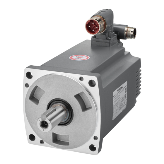
When unpacking the drive package, check whether the following components are included. Component Illustration Rated power Outline dimension Frame size (kW) (Width x Height x Depth, mm) SINAMICS V90 servo drive 60 x 180 x 200 FSAA 0.75/1.0 80 x 180 x 200 1.5/2.0 100 x 180 x 220 3.5/5.0/7.0... - Page 28 General information 2.1 Deliverables Drive rating plate ① ⑤ Drive name Order number ② ⑥ Power input Product serial number ③ ⑦ Power output Part number ④ Rated motor power SINAMICS V90, SIMOTICS S-1FL6 Operating Instructions, 07/2015, 6SL3298-0AV60-0BP0...
-
Page 29: Motor Components
SIMOTICS S-1FL6 servo motor 1.27 • 2.39 • 3.58 • 4.78 • 7.16 • 8.36 • 9.55 • 11.90 • 16.70 • 23.90 • 33.40 • User documentation SIMOTICS S-1FL6 Servo Motors Installation Guide SINAMICS V90, SIMOTICS S-1FL6 Operating Instructions, 07/2015, 6SL3298-0AV60-0BP0... - Page 30 Thermal class Motor ID ④ ⑩ ⑯ Rated torque Degree of protection Weight ⑤ ⑪ ⑰ Stall torque Motor operating mode Maximum speed ⑥ ⑫ ⑱ Rated voltage Stall current Rated speed SINAMICS V90, SIMOTICS S-1FL6 Operating Instructions, 07/2015, 6SL3298-0AV60-0BP0...
-
Page 31: Device Combination
General information 2.2 Device combination Device combination The table below shows the combination of SINAMICS V90 servo drives and SIMOTICS S- 1FL6 servo motors. SIMOTICS S-1FL6 servo motor SINAMICS V90 servo drive Rated Rated Rated Shaft Motor ID Order number... -
Page 32: Product Overview
General information 2.3 Product overview Product overview SINAMICS V90 servo drives ● FSAA and FSA ● FSB and FSC SINAMICS V90, SIMOTICS S-1FL6 Operating Instructions, 07/2015, 6SL3298-0AV60-0BP0... - Page 33 General information 2.3 Product overview SIMOTICS S-1FL6 servo motors SINAMICS V90, SIMOTICS S-1FL6 Operating Instructions, 07/2015, 6SL3298-0AV60-0BP0...
-
Page 34: System Configuration
The SINAMICS V90 servo drive is integrated with digital input/output interface, pulse train interface and analog interface. It can be connected either to a Siemens controller like S7-200, S7-1200 or S7-200 SMART, or to a third-party controller. Absolute position information can be read from the servo drive by the PLC via RS485 port. -
Page 35: Accessories
Type Length Order No. Type Order No. Type Order No. 6FX3002-... 6FX2003-... 6FX2003-... Brake cable 5BL02-1AD0 Brake connector 0LL51 (a1) (a2) 5BL02-1AF0 5BL02-1AH0 10 m 5BL02-1BA0 15 m 5BL02-1BF0 20 m 5BL02-1CA0 SINAMICS V90, SIMOTICS S-1FL6 Operating Instructions, 07/2015, 6SL3298-0AV60-0BP0... - Page 36 ΔU [V] = 0.042 Ω·mm /m ∙ (l/q) ∙ I Brake Where: l = Cable length [m], q = Brake cable cross section [mm ], I = DC current of brake [A] Brake SINAMICS V90, SIMOTICS S-1FL6 Operating Instructions, 07/2015, 6SL3298-0AV60-0BP0...
- Page 37 4DA10 600 VAC 690 VAC 1021- 4DA10 Braking resistor The SINAMICS V90 has a built-in braking resistor, the table below shows the information of the built-in resistor: Frame size Resistance (Ω) Max. power (kW) Rated power (W) Max. energy (kJ) FSAA 13.7...
- Page 38 189.6 Filter Siemens recommends you to use a line filter to protect the system from high frequency noise. The line filter restricts the conductive interference emitted from the SINAMICS V90 to the permissible values. The SINAMICS V90 drives with these external line filters have been tested in accordance with the emission requirements of the Category C2 environment.
- Page 39 Noise frequency (MHz) 0.15 CM (dB) DM (dB) Rated current 12 A Noise frequency (MHz) 0.15 CM (dB) DM (dB) Rated current 20 A Noise frequency (MHz) 0.15 CM (dB) DM (dB) SINAMICS V90, SIMOTICS S-1FL6 Operating Instructions, 07/2015, 6SL3298-0AV60-0BP0...
- Page 40 2 GB from manufacturers such as KINGMAX, Kingston or SanDisk. Replacement fans (for frame sizes B and C only) Order numbers: Fan kits for frame size B: 6SL3200-0WF00-0AA0 Fan kits for frame size C: 6SL3200-0WF01-0AA0 SINAMICS V90, SIMOTICS S-1FL6 Operating Instructions, 07/2015, 6SL3298-0AV60-0BP0...
-
Page 41: Function List
Stops motor and clamps the motor shaft when motor speed setpoint is below a parameterized threshold level Modbus communication (Page 185) Supports the communication between the SINAMICS V90 PTI, IPos, S, T servo drive and PLC with the standard Modbus commica-... - Page 42 S-curve profile with a parameterized time constant SINAMICS V-ASSISTANT You can perform parameter settings, test operation, ad- PTI, IPos, S, T justment and other operations with a PC SINAMICS V90, SIMOTICS S-1FL6 Operating Instructions, 07/2015, 6SL3298-0AV60-0BP0...
-
Page 43: Technical Data
Analog speed command 1:2000, internal speed command 1:5000 mode Analog speed command -10 VDC to +10 VDC/rated speed input Torque limit Set through a parameter or the analog input command (0 V - +10 VDC/max. torque) SINAMICS V90, SIMOTICS S-1FL6 Operating Instructions, 07/2015, 6SL3298-0AV60-0BP0... - Page 44 Operating environment Indoors (without direct sunlight), free from corrosive gas, combustible gas, oil gas, or dust Altitude ≤ 1000 m (without power derating) Degree of protection IP20 Degree of pollution Class 2 SINAMICS V90, SIMOTICS S-1FL6 Operating Instructions, 07/2015, 6SL3298-0AV60-0BP0...
- Page 45 6.615 6.615 When SINAMICS V90 works with a motor with a brake, the voltage tolerance of 24 VDC power supply must be -10% to +10% to meet the voltage requirement of the brake. Integral solid state short circuit protection does not provide branch circuit protection. Branch circuit protection must be provided in accordance with the National Electrical Code and any additional local codes.
-
Page 46: Technical Data - Servo Motors
Type of construction IM B5, IM V1 and IM V3 Positive rotation Clockwise (default setting in SINAMICS V90 servo drives) Certification Restricted emergency stop operation is permissible. Up to 2000 braking operations can be executed with 300% rotor moment of inertia as external moment of inertia from a speed of 3000 RPM without the brake being subject to an inad- missible amount of wear. - Page 47 When the surrounding temperature is higher than 30 °C, the 1FL6096 motors with brake will have a power derating of 10%. Note The data of rated torque, rated power, and maximum torque in the above table allow a tolerance of 10%. SINAMICS V90, SIMOTICS S-1FL6 Operating Instructions, 07/2015, 6SL3298-0AV60-0BP0...
- Page 48 0.89 0.84 2000 1.00 0.94 0.90 0.86 0.82 2500 0.96 0.90 0.86 0.83 0.78 3000 0.92 0.86 0.82 0.79 0.75 3500 0.88 0.82 0.79 0.75 0.71 4000 0.82 0.77 0.74 0.71 0.67 SINAMICS V90, SIMOTICS S-1FL6 Operating Instructions, 07/2015, 6SL3298-0AV60-0BP0...
- Page 49 General information 2.7 Technical data Torque-Speed characteristics SINAMICS V90, SIMOTICS S-1FL6 Operating Instructions, 07/2015, 6SL3298-0AV60-0BP0...
- Page 50 20 m. • For 1FL6096 motors, the maximum speed can be ensured when the line supply voltage is higher than 380 V. Permissible radial and axial forces SINAMICS V90, SIMOTICS S-1FL6 Operating Instructions, 07/2015, 6SL3298-0AV60-0BP0...
-
Page 51: Technical Data - Cables
600/1000 Operation temperature (°C) -25 to 80 Shielding Minimum bending radius, static 6 x outer diameter (mm) Bending cycles 1000000 Oil resistance EN60811-2-1 fulfilled Flame-retardant EN60332-1-1to 1-3 fulfilled Certifications RoHS, UL, CE SINAMICS V90, SIMOTICS S-1FL6 Operating Instructions, 07/2015, 6SL3298-0AV60-0BP0... - Page 52 General information 2.7 Technical data SINAMICS V90, SIMOTICS S-1FL6 Operating Instructions, 07/2015, 6SL3298-0AV60-0BP0...
-
Page 53: Mounting
10 mm. In this case, the minimum mounting clearance should not be less than 5 mm. • The surrounding temperature is 45 °C to 55 °C. In this case, the minimum mounting clearance should not be less than 20 mm. SINAMICS V90, SIMOTICS S-1FL6 Operating Instructions, 07/2015, 6SL3298-0AV60-0BP0... -
Page 54: Drill Patterns And Outline Dimensions
Mounting 3.1 Mounting the drive 3.1.2 Drill patterns and outline dimensions SINAMICS V90, SIMOTICS S-1FL6 Operating Instructions, 07/2015, 6SL3298-0AV60-0BP0... - Page 55 Mounting 3.1 Mounting the drive SINAMICS V90, SIMOTICS S-1FL6 Operating Instructions, 07/2015, 6SL3298-0AV60-0BP0...
-
Page 56: Mounting The Drive
Mounting 3.1 Mounting the drive 3.1.3 Mounting the drive Note Taking EMC factors into account, you are recommended to mount the drive in a shielded cabinet. SINAMICS V90, SIMOTICS S-1FL6 Operating Instructions, 07/2015, 6SL3298-0AV60-0BP0... -
Page 57: Mounting The Motor
(weight force of the drive elements) and the necessary degree of protection. Motor dimensions Shaft-height 45 mm, with incremental encoder (unit: mm) Rated power Rated torque 0.4 kW 1.27 Nm 154.5 169.5 61.5 0.75 kW 2.39 Nm 201.5 216.5 SINAMICS V90, SIMOTICS S-1FL6 Operating Instructions, 07/2015, 6SL3298-0AV60-0BP0... - Page 58 Shaft-height 65 mm, with incremental encoder (unit: mm) Rated power Rated torque 0.75 kW 3.58 Nm 202.5 69.5 1.0 kW 4.78 Nm 235.5 1.5 kW 7.16 Nm 235.5 1.75 kW 8.36 Nm 268.5 2.0 kW 9.55 Nm 301.5 SINAMICS V90, SIMOTICS S-1FL6 Operating Instructions, 07/2015, 6SL3298-0AV60-0BP0...
- Page 59 Shaft-height 90 mm, with incremental encoder (unit: mm) Rated power Rated torque 2.5 kW 11.9 Nm 189.5 210.5 98.5 3.5 kW 16.7 Nm 211.5 236.5 5.0 kW 23.9 Nm 237.5 262.5 7.0 kW 33.4 Nm 289.5 314.5 SINAMICS V90, SIMOTICS S-1FL6 Operating Instructions, 07/2015, 6SL3298-0AV60-0BP0...
-
Page 60: Mounting The Motor
During motor installation or operation, make sure that no liquid (water, oil, etc.) can penetrate into the motor. Besides, when installing the motor horizontally, make sure that the cable outlet faces downward to protect the motor from ingress of oil or water. SINAMICS V90, SIMOTICS S-1FL6 Operating Instructions, 07/2015, 6SL3298-0AV60-0BP0... - Page 61 270 x 270 x 10 (mm) 8 Nm Aluminum alloy 1FL606❑ 4 x M8 390 x 390 x 15 (mm) 20 Nm 1FL609❑ 4 x M12 420 x 420 x 20 (mm) 85 Nm SINAMICS V90, SIMOTICS S-1FL6 Operating Instructions, 07/2015, 6SL3298-0AV60-0BP0...
- Page 62 Mounting 3.2 Mounting the motor SINAMICS V90, SIMOTICS S-1FL6 Operating Instructions, 07/2015, 6SL3298-0AV60-0BP0...
-
Page 63: Connecting
Connecting System connection The SINAMICS V90 servo system is connected as follows: SINAMICS V90, SIMOTICS S-1FL6 Operating Instructions, 07/2015, 6SL3298-0AV60-0BP0... - Page 64 The cable shields of shielded twisted-pair cables should be connected to the shielding plate or the cable clamp of the servo drive. Note The mini-USB interface of the SINAMICS V90 is used for fast commissioning and diagnostics with SINAMICS V-ASSISTANT installed in the PC. Do not use it for long monitoring.
-
Page 65: Main Circuit Wirings
Line phase L1 Line phase L2 Line phase L3 Maximum conductor cross-section: FSAA and FSA: 1.5 mm (M2.5 screws, 4.43 lb.in/0.5 Nm) FSB and FSC: 2.5 mm (M4 screws, 19.91 lb.in/2.25 Nm) SINAMICS V90, SIMOTICS S-1FL6 Operating Instructions, 07/2015, 6SL3298-0AV60-0BP0... -
Page 66: Motor Power - U, V, W
(M2.5 screws, 4.43 lb.in/0.5 Nm) FSB and FSC: 2.5 mm (M4 screws, 19.91 lb.in/2.25 Nm) Power connector - motor side Illustration Pin No. Signal Description Phase U Phase V Phase W Protective Earthing Wiring SINAMICS V90, SIMOTICS S-1FL6 Operating Instructions, 07/2015, 6SL3298-0AV60-0BP0... -
Page 67: Control/Status Interface - X8
A (+) pulse train encoder output A (+) PTIA_D- High-speed 5 V differential PTOA- High-speed 5 V differential pulse train input A (-) pulse train encoder output A (-) SINAMICS V90, SIMOTICS S-1FL6 Operating Instructions, 07/2015, 6SL3298-0AV60-0BP0... - Page 68 Analog input channel 1, nega- AO_M Analog output ground tive AI2+ Analog input channel 2, posi- Analog output channel 2 tive AI2- Analog input channel 2, nega- tive None Reserved Reserved Reserved Reserved SINAMICS V90, SIMOTICS S-1FL6 Operating Instructions, 07/2015, 6SL3298-0AV60-0BP0...
-
Page 69: Digital Inputs/Outputs (Dis/Dos)
4.3 Control/Status interface - X8 4.3.1 Digital inputs/outputs (DIs/DOs) SINAMICS V90 supports free assignment of signals to the following digital input and output terminals depending on the control mode selected: DI1 to DI8 -- Assignable with parameters p29301 to p29308... -
Page 70: Dis
Connecting 4.3 Control/Status interface - X8 4.3.1.1 You can assign a maximum of 28 internal digital input signals to the SINAMICS V90 servo drive. For detailed information about these signals, see the table below: Name Type Description Control mode IPos... - Page 71 Torque setpoint selection. ✓ This signal can select two torque setpoint sources (one external torque setpoint, one fixed torque set- point). 0: external torque setpoint (analog input 2) • 1: fixed torque setpoint • SINAMICS V90, SIMOTICS S-1FL6 Operating Instructions, 07/2015, 6SL3298-0AV60-0BP0...
- Page 72 When working in the torque control mode, the torque setpoint equals to 0 if CWE and CCWE are at the same status. For more information, please refer to section Direction and stop (Page 182). SINAMICS V90, SIMOTICS S-1FL6 Operating Instructions, 07/2015, 6SL3298-0AV60-0BP0...
- Page 73 The parameter p29300 has higher priority than the DIs. The bit 6 of p29300 is used for emergency stop. You are not allowed to modify it when the drive is in the servo on state. SINAMICS V90, SIMOTICS S-1FL6 Operating Instructions, 07/2015, 6SL3298-0AV60-0BP0...
-
Page 74: Dos
NPN wiring PNP wiring 4.3.1.2 You can assign a maximum of 13 internal digital output signals to the SINAMICS V90 servo drive. For detailed information about these signals, see the table below: Name Descriptions Control mode... - Page 75 See note below. WARNING2 Warning 2 condition reached ✓ ✓ ✓ ✓ 1: parameterizable warning 2 condition has been • reached 0: warning 2 condition has not been reached. • See note below SINAMICS V90, SIMOTICS S-1FL6 Operating Instructions, 07/2015, 6SL3298-0AV60-0BP0...
- Page 76 If warning condition assigned to p29340 occurs, WARNING1 becomes ON. If warning condition assigned to p29341 occurs, WARNING2 becomes ON. Wiring The digital outputs only support NPN type of wiring as illustrated below: SINAMICS V90, SIMOTICS S-1FL6 Operating Instructions, 07/2015, 6SL3298-0AV60-0BP0...
-
Page 77: Pulse Train Inputs/Encoder Outputs (Ptis/Ptos)
Pulse train inputs/encoder outputs (PTIs/PTOs) 4.3.2.1 PTIs Two channels of pulse train input are available for the SINAMICS V90 servo drive: ● 24 V single end pulse train input ● High-speed 5 V differential pulse train input (RS485) When using the 24 V single end PTI:... -
Page 78: Ptos
When not using the open collector: When using the open collector: 4.3.3 Analog inputs/outputs (AIs/AOs) 4.3.3.1 SINAMICS V90 has two analog input terminals. The input voltage at each analog input varies with control modes. Pin No. Analog input Input voltage... -
Page 79: Aos
The command voltage of the analog inputs always follows the formula below: = (AI+) - (AI-) input 4.3.3.2 The SINAMICS V90 has two analog outputs. You can find detailed information about these two analog outputs from the table below: Pin No. Analog output... - Page 80 Connecting 4.3 Control/Status interface - X8 Wiring Do wiring of analog outputs as follows: SINAMICS V90, SIMOTICS S-1FL6 Operating Instructions, 07/2015, 6SL3298-0AV60-0BP0...
-
Page 81: Standard Application Wirings (Factory Setting)
Connecting 4.3 Control/Status interface - X8 4.3.4 Standard application wirings (factory setting) 4.3.4.1 Pulse train input position control (PTI) Standard wiring for pulse train input position control mode: SINAMICS V90, SIMOTICS S-1FL6 Operating Instructions, 07/2015, 6SL3298-0AV60-0BP0... - Page 82 Digital inputs, supporting both PNP and NPN types. The 24 V power supplies in the connection diagram are as follows: 24 V power supply for SINAMICS V90. All the PTO signals must be connected to the controller with the same 24 V power supply as SINAMICS V90.
-
Page 83: Internal Position Control (Ipos)
Connecting 4.3 Control/Status interface - X8 4.3.4.2 Internal position control (IPos) Standard wiring for internal position control mode: SINAMICS V90, SIMOTICS S-1FL6 Operating Instructions, 07/2015, 6SL3298-0AV60-0BP0... - Page 84 Digital inputs, supporting both PNP and NPN types. The 24 V power supplies in the connection diagram are as follows: 24 V power supply for SINAMICS V90. All the PTO signals must be connected to the controller with the same 24 V power supply as SINAMICS V90.
-
Page 85: Speed Control (S)
Connecting 4.3 Control/Status interface - X8 4.3.4.3 Speed control (S) Standard wiring for speed control mode: SINAMICS V90, SIMOTICS S-1FL6 Operating Instructions, 07/2015, 6SL3298-0AV60-0BP0... - Page 86 Digital inputs, supporting both PNP and NPN types. The 24 V power supplies in the connection diagram are as follows: 24 V power supply for SINAMICS V90. All the PTO signals must be connected to the controller with the same 24 V power supply as SINAMICS V90.
-
Page 87: Torque Control (T)
Connecting 4.3 Control/Status interface - X8 4.3.4.4 Torque control (T) Standard wiring for torque control mode: SINAMICS V90, SIMOTICS S-1FL6 Operating Instructions, 07/2015, 6SL3298-0AV60-0BP0... - Page 88 Digital inputs, supporting both PNP and NPN types. The 24 V power supplies in the connection diagram are as follows: 24 V power supply for SINAMICS V90. All the PTO signals must be connected to the controller with the same 24 V power supply as SINAMICS V90.
-
Page 89: Connection Examples With Plcs
You can assign different digital inputs/outputs based on your actual requirement. 4.3.5.1 SIMATIC S7-200 SMART Pulse train input position control (PTI) When connect to different axes, the outputs are different. The diagram below take the connection with axis 0 as example. SINAMICS V90, SIMOTICS S-1FL6 Operating Instructions, 07/2015, 6SL3298-0AV60-0BP0... - Page 90 300 rpm. The resistor R (200 Ohm to 500 Ohm, recommended power ≥ 5 W ) is required only if the PTI input frequency exceeds 100 KHz. Internal position control (IPos) SINAMICS V90, SIMOTICS S-1FL6 Operating Instructions, 07/2015, 6SL3298-0AV60-0BP0...
- Page 91 Connecting 4.3 Control/Status interface - X8 Speed control (S) SINAMICS V90, SIMOTICS S-1FL6 Operating Instructions, 07/2015, 6SL3298-0AV60-0BP0...
- Page 92 Connecting 4.3 Control/Status interface - X8 Torque control (T) SINAMICS V90, SIMOTICS S-1FL6 Operating Instructions, 07/2015, 6SL3298-0AV60-0BP0...
-
Page 93: Simatic S7-200
The resistor R3 (200 Ohm to 500 Ohm) is required only if the speed for searching the zero position exceeds 300 rpm. The resistor R (200 Ohm to 500 Ohm, recommended power ≥ 5 W ) is required only if the PTI input frequency exceeds 100 KHz. SINAMICS V90, SIMOTICS S-1FL6 Operating Instructions, 07/2015, 6SL3298-0AV60-0BP0... - Page 94 Connecting 4.3 Control/Status interface - X8 Internal position control (IPos) SINAMICS V90, SIMOTICS S-1FL6 Operating Instructions, 07/2015, 6SL3298-0AV60-0BP0...
- Page 95 Connecting 4.3 Control/Status interface - X8 Speed control (S) SINAMICS V90, SIMOTICS S-1FL6 Operating Instructions, 07/2015, 6SL3298-0AV60-0BP0...
- Page 96 Connecting 4.3 Control/Status interface - X8 Torque control (T) SINAMICS V90, SIMOTICS S-1FL6 Operating Instructions, 07/2015, 6SL3298-0AV60-0BP0...
-
Page 97: Simatic S7-1200
The resistor R3 (200 Ohm to 500 Ohm) is required only if the speed for searching the zero position exceeds 300 rpm. The resistor R (200 Ohm to 500 Ohm, recommended power ≥ 5 W ) is required only if the PTI input frequency exceeds 100 KHz. SINAMICS V90, SIMOTICS S-1FL6 Operating Instructions, 07/2015, 6SL3298-0AV60-0BP0... - Page 98 Connecting 4.3 Control/Status interface - X8 Internal position control (IPos) SINAMICS V90, SIMOTICS S-1FL6 Operating Instructions, 07/2015, 6SL3298-0AV60-0BP0...
- Page 99 Connecting 4.3 Control/Status interface - X8 Speed control (S) SINAMICS V90, SIMOTICS S-1FL6 Operating Instructions, 07/2015, 6SL3298-0AV60-0BP0...
- Page 100 Connecting 4.3 Control/Status interface - X8 Torque control (T) SINAMICS V90, SIMOTICS S-1FL6 Operating Instructions, 07/2015, 6SL3298-0AV60-0BP0...
-
Page 101: Power Supply/Sto - X6
STO interfaces. If you do not need to use it any more, you must reinsert the short-circuit stick; otherwise, the motor will not run. For detailed information about the STO function, refer to "Safety Integrated basic functions (Page 218)". SINAMICS V90, SIMOTICS S-1FL6 Operating Instructions, 07/2015, 6SL3298-0AV60-0BP0... -
Page 102: Encoder Interface - X9
Connecting 4.5 Encoder interface - X9 Plugging the 24 V power supply and STO cables Encoder interface - X9 The SINAMICS V90 servo drive supports two kinds of encoders: ● Incremental encoder ● Absolute encoder NOTICE Cable shielding The encoder cable must be shielded to meet the EMC requirements. - Page 103 Power supply 0 Phase A+ n. c. Not connected Phase A- Clock_N Inverted clock Phase B+ Data_P Data Phase B- Clock_P Clock Phase R+ n. c. Not connected Phase R- Data_N Inverted data SINAMICS V90, SIMOTICS S-1FL6 Operating Instructions, 07/2015, 6SL3298-0AV60-0BP0...
- Page 104 4.6 External braking resistor - DCP, R1 Wiring Grounding To ensure better EMC effects, you are recommended to strip the encoder cable and connect the cable shield to earth, as shown in the following figure: SINAMICS V90, SIMOTICS S-1FL6 Operating Instructions, 07/2015, 6SL3298-0AV60-0BP0...
-
Page 105: External Braking Resistor - Dcp, R1
For the connection of the external braking resistor, refer to System connection (Page 63). Motor holding brake - X7 You can connect the SINAMICS V90 servo drive to a servo motor with brake to use the function of motor holding brake. -
Page 106: Rs485 Interface - X12
Description Brake+ Phase Brake+ Brake- Phase Brake- Wiring RS485 interface - X12 The SINAMICS V90 servo drives support communication with the PLCs through the RS485 interface over the USS or MODBUS protocol. Pin assignment Illustration Signal name Description Reserved Do not use... -
Page 107: Commissioning
• Do not switch off the drive power supply when the data transfer from the SD card to the drive is in process. SINAMICS V90, SIMOTICS S-1FL6 Operating Instructions, 07/2015, 6SL3298-0AV60-0BP0... -
Page 108: Initial Commissioning In Jog Mode
SINAMICS V-ASSISTANT is a software tool that can be installed on a PC and runs on the Windows operating system. It communicates with the SINAMICS V90 servo drive with a USB cable. With SINAMICS V-ASSISTANT, you can change drive parameters and monitor drive working states in online mode. - Page 109 For detailed information about the parameter setting / saving with the BOP, refer to the sections "Basic opera- tions (Page 123)" or "Saving parameters (RAM to ROM) (Page 129)". Switch on the 3-phase 380 VAC power supply. SINAMICS V90, SIMOTICS S-1FL6 Operating Instructions, 07/2015, 6SL3298-0AV60-0BP0...
-
Page 110: Commissioning In Pulse Train Position Control Mode (Pti)
+ direction, negative logic • p29010=3: AB track, negative logic • The factory setting is p29010=0 (pulse + direction, positive logic). Refer to "Selecting a setpoint pulse train input form (Page 144)". SINAMICS V90, SIMOTICS S-1FL6 Operating Instructions, 07/2015, 6SL3298-0AV60-0BP0... - Page 111 Calculate the electronic gear ratio by selecting me- • chanical structure. – For more information, see SINAMICS V90 V- ASSISTANT Online Help. Refer to "Electronic gear ratio (Page 145)". Set the torque limitation and speed limitation. Refer to "Torque limit (Page 151)" and "Speed limit (Page 150)".
-
Page 112: Commissioning In Internal Position Control Mode (Ipos)
Refer to "Setting fixed position setpoint (Page 158)". p2617[7] and p2618[0] to p2618[7]) according to mechanism. Set the torque limitation and speed limitation. Refer to "Torque limit (Page 171)" and "Speed limit (Page 171)". SINAMICS V90, SIMOTICS S-1FL6 Operating Instructions, 07/2015, 6SL3298-0AV60-0BP0... - Page 113 (Page 171)". The system commissioning in internal position control You can check the system performance. If it is not satis- mode ends. fied, you can adjust it. Refer to "Tuning (Page 223)". SINAMICS V90, SIMOTICS S-1FL6 Operating Instructions, 07/2015, 6SL3298-0AV60-0BP0...
-
Page 114: Commissioning In Speed Control Mode (S)
If the external analog speed setpoint is used, configure the maximum analog speed setpoint corresponding to 10 V by setting parameter p29060. Set the torque limitation and speed limitation. Refer to "Torque limit (Page 176)" and "Speed limit (Page 176)". SINAMICS V90, SIMOTICS S-1FL6 Operating Instructions, 07/2015, 6SL3298-0AV60-0BP0... -
Page 115: Commissioning In Torque Control Mode (T)
Switch to the torque control mode by setting Refer to "Compound controls (Page 135)". p29003=3. Save the parameter and restart the servo drive to apply the setting of the torque control mode. SINAMICS V90, SIMOTICS S-1FL6 Operating Instructions, 07/2015, 6SL3298-0AV60-0BP0... - Page 116 Refer to "Actual status display (Page 122)". The system commissioning in torque control mode You can check the system performance. If it is not satis- ends. fied, you can adjust it. Refer to "Tuning (Page 223)". SINAMICS V90, SIMOTICS S-1FL6 Operating Instructions, 07/2015, 6SL3298-0AV60-0BP0...
-
Page 117: Basic Operator Panel (Bop)
Basic operator panel (BOP) BOP overview The SINAMICS V90 servo drive is designed with a Basic Operator Panel (BOP) on the front panel of the servo drive: You can use the BOP for the following operations: ● Standalone commissioning ● Diagnosis ●... -
Page 118: Bop Display
(Page 124)". P 0x Parameter group Six groups are available: 1. P0A: basic 2. P0B: gain adjustment 3. P0C: speed control 4. P0D: torque control 5. P0E: position control 6. P0F: IO SINAMICS V90, SIMOTICS S-1FL6 Operating Instructions, 07/2015, 6SL3298-0AV60-0BP0... - Page 119 Position following error The communication between the SINAMICS V-ASSISTANT and the servo drive is established. In this case, the BOP is protected from any operations except clear- ing alarms and acknowledging faults. SINAMICS V90, SIMOTICS S-1FL6 Operating Instructions, 07/2015, 6SL3298-0AV60-0BP0...
-
Page 120: Control Buttons
Moves current display to the left page when is displayed at the upper right corner, for example Moves current display to the right page when is displayed at the lower right corner, for example SINAMICS V90, SIMOTICS S-1FL6 Operating Instructions, 07/2015, 6SL3298-0AV60-0BP0... -
Page 121: Parameter Structure
Basic operator panel (BOP) 6.2 Parameter structure Parameter structure The overall parameter structure of SINAMICS V90 BOP is designed as follows: SINAMICS V90, SIMOTICS S-1FL6 Operating Instructions, 07/2015, 6SL3298-0AV60-0BP0... -
Page 122: Actual Status Display
With p29002, you define which of the following drive operating status data is to be displayed on the BOP.: Parameter Value Meaning p29002 0 (default) Actual speed DC voltage Actual torque Actual position Position following error Note Make sure you save p29002 after modification. SINAMICS V90, SIMOTICS S-1FL6 Operating Instructions, 07/2015, 6SL3298-0AV60-0BP0... -
Page 123: Basic Operations
You can only read values of these parameters. Parameters with index Some parameters have several indices. Each index has its own meaning and corresponding value. Parameters without index All parameters that do not have indices are parameters without index. SINAMICS V90, SIMOTICS S-1FL6 Operating Instructions, 07/2015, 6SL3298-0AV60-0BP0... -
Page 124: Editing Parameters
● Method 2: move the cursor to a digit with the SHIFT button, then change the digit value with the UP or DOWN button If you edit a parameter value with Method 1, proceed as follows: SINAMICS V90, SIMOTICS S-1FL6 Operating Instructions, 07/2015, 6SL3298-0AV60-0BP0... - Page 125 It is forbidden to use this function when the servo is ON. Use this function when the servo is OFF. Note The parameters p1414 and p1656 cannot be changed using the SHIFT button. SINAMICS V90, SIMOTICS S-1FL6 Operating Instructions, 07/2015, 6SL3298-0AV60-0BP0...
-
Page 126: Viewing Parameters
If you do not know which group that a parameter belongs to, you can find it in the "P ALL" menu. Note Invalid parameter number If the input parameter number is unavailable, the nearest parameter number to the input value is displayed. SINAMICS V90, SIMOTICS S-1FL6 Operating Instructions, 07/2015, 6SL3298-0AV60-0BP0... -
Page 127: Auxiliary Functions
Copy parameter set from drive to an SD Adjust absolute encoder card NOTE: This function is available only when the servo motor with an absolute encoder is connected. ⑤ Copy parameter set from an SD card to drive SINAMICS V90, SIMOTICS S-1FL6 Operating Instructions, 07/2015, 6SL3298-0AV60-0BP0... -
Page 128: Jog
To run the connected motor with the Jog function and view the Jog torque, proceed as follows: Jog in torque (example) NOTICE Exit the Jog mode after completing Jog run. The servo motor cannot run if the servo drive is in the Jog mode. SINAMICS V90, SIMOTICS S-1FL6 Operating Instructions, 07/2015, 6SL3298-0AV60-0BP0... -
Page 129: Saving Parameters (Ram To Rom)
Editing parameters (Page 124) 6.5.3 Setting parameters to default This function is used to reset all parameters to their default values. To reset the parameters to their default values, proceed as follows: SINAMICS V90, SIMOTICS S-1FL6 Operating Instructions, 07/2015, 6SL3298-0AV60-0BP0... -
Page 130: Transferring Data (Drive To Sd)
Do not plug or unplug the SD card during copying; otherwise, the copying operation will fail. Note Write protection function is not supported by SINAMICS V90. Data in the SD card will be overwritten even if the write protection function of the SD card is enabled. -
Page 131: Transferring Data (Sd To Drive)
SD card and insert it into the SD card slot. After that, proceed as follows: After you have updated the firmware, you need to set parameters to their default values. Refer to "Setting parameters to default (Page 129)" about the default process. SINAMICS V90, SIMOTICS S-1FL6 Operating Instructions, 07/2015, 6SL3298-0AV60-0BP0... -
Page 132: Adjusting Ai Offsets
6.5.7 Adjusting AI offsets NOTICE Connect to ground You must firstly connect the AI1 or AI2 to ground and then adjust AI offset. Refer to section "Analog inputs (Page 78)". SINAMICS V90, SIMOTICS S-1FL6 Operating Instructions, 07/2015, 6SL3298-0AV60-0BP0... - Page 133 AI offset. Parameter range p29042 or p29061 ranges from -0.5 V to + 0.5 V. A value that is out of this range causes an alarm. Refer to chapter "Parameter list (Page 253)". SINAMICS V90, SIMOTICS S-1FL6 Operating Instructions, 07/2015, 6SL3298-0AV60-0BP0...
-
Page 134: Adjusting An Absolute Encoder
With the BOP function menu "ABS", you can set current position of absolute encoder to be zero position. To do this, proceed as follows: Note Save parameter The position value is set in parameter p2525. You must save the parameters after setting the zero position. SINAMICS V90, SIMOTICS S-1FL6 Operating Instructions, 07/2015, 6SL3298-0AV60-0BP0... -
Page 135: Control Functions
Control functions Compound controls Control modes Nine control modes are available for the SINAMICS V90 servo drive: Control modes Abbreviation Basic control modes Pulse train input position control mode (PTI) Internal position control mode (IPos) IPos Speed control mode (S) -
Page 136: General Functions
ON = rising edge Servo motor circuit is connected (servo is ON). setting) Servo motor is ready to run. OFF = falling Servo motor circuit is shut off (servo is OFF). Servo edge motor is not ready to run. SINAMICS V90, SIMOTICS S-1FL6 Operating Instructions, 07/2015, 6SL3298-0AV60-0BP0... -
Page 137: Direction Of Motor Rotation
Negative p29001 CW is forward direction Analog monitoring: Analog monitoring: • • (factory setting) PTO: • PTO: • CCW is forward direction Analog monitoring: Analog monitoring: • • PTO: • PTO: • SINAMICS V90, SIMOTICS S-1FL6 Operating Instructions, 07/2015, 6SL3298-0AV60-0BP0... -
Page 138: Over-Travel
To clear the fault, acknowledge it with RESET, and then leave away from the STOP cam minus in the positive traversing direction to return the axis to the valid traversing range. SINAMICS V90, SIMOTICS S-1FL6 Operating Instructions, 07/2015, 6SL3298-0AV60-0BP0... - Page 139 Set CCWL at high level or rising edge forcedly. Note DI parameterization Refer to Section "DIs (Page 70)" for detailed information about DI parameterization. Refer to Chapter "Parameters (Page 253)" for detailed information about parameters. SINAMICS V90, SIMOTICS S-1FL6 Operating Instructions, 07/2015, 6SL3298-0AV60-0BP0...
-
Page 140: Motor Holding Brake
6 (TLR) Assignment of digital output 5 p29335 1 to 13 8 (MBR) Assignment of digital output 6 Note Refer to Section "DOs (Page 74)" for detailed information about the digital outputs. SINAMICS V90, SIMOTICS S-1FL6 Operating Instructions, 07/2015, 6SL3298-0AV60-0BP0... - Page 141 3: SIEMENS internal use • When you set p1215=1, the motor holding brake is open once the digital input signal SON has a rising edge and becomes closed once a falling edge comes to SON. SINAMICS V90, SIMOTICS S-1FL6 Operating Instructions, 07/2015, 6SL3298-0AV60-0BP0...
-
Page 142: Stopping Method At Servo Off
Pin assignment Setting Description EMGS X8-13 (fixed) Servo drive is ready to run. Emergency stop. For detailed information about the digital input signals SON and EMGS, refer to Section "DIs (Page 70)". SINAMICS V90, SIMOTICS S-1FL6 Operating Instructions, 07/2015, 6SL3298-0AV60-0BP0... -
Page 143: Pulse Train Input Position Control (Pti)
Pulse train input position control (PTI) 7.3.1 Sequence of SON When the SINAMICS V90 servo drive operates in pulse train input position control mode (PTI), the pulse train setpoint must be send out after the RDY signal is ok. Timing diagram 7.3.2... -
Page 144: Selecting A Setpoint Pulse Train Input Form
7.3 Pulse train input position control (PTI) 7.3.3 Selecting a setpoint pulse train input form The SINAMICS V90 servo drive supports two kinds of setpoint pulse train input forms: ● AB track pulse ● Pulse + Direction For both forms, positive logic and negative logic are supported:... -
Page 145: Smoothing Function
Smoothes the parameter in response to a sudden posi- tion setpoint 7.3.6 Electronic gear ratio Encoder specifications The encoder specifications are shown as follows: Type Resolution Incremental encoder 2500 ppr Absolute encoder 20 bit single turn + 12 bit multi-turn SINAMICS V90, SIMOTICS S-1FL6 Operating Instructions, 07/2015, 6SL3298-0AV60-0BP0... - Page 146 (p29013) are used for the four electronic gear ratios: Parameter Range Factory setting Unit Description p29012[0] 1 to 10000 The first numerator of electronic gear p29012[1] 1 to 10000 The second numerator of electronic gear SINAMICS V90, SIMOTICS S-1FL6 Operating Instructions, 07/2015, 6SL3298-0AV60-0BP0...
- Page 147 The range of electronic gear ratio is from 0.02 to 200. The electronic gear ratio can be set at SERVO OFF state only. After the setting, you need to reference the drive again. SINAMICS V90, SIMOTICS S-1FL6 Operating Instructions, 07/2015, 6SL3298-0AV60-0BP0...
- Page 148 Calculate electronic (1/6000) × (1/1) × 10000 = 10000/6000 (1/36000) × (3/1) × 10000 = 10000/12000 gear ratio Set param- p29012/p = 10000/6000 = 5/3 = 10000/12000 = 5/6 eters 29013 SINAMICS V90, SIMOTICS S-1FL6 Operating Instructions, 07/2015, 6SL3298-0AV60-0BP0...
-
Page 149: Inhibiting Pulse Train Input Setpoint (P-Trg)
• The signal P-TRG is active only when the digital input signal SON is in OFF state. • When the signal P-TRG is active in the PTI mode or a compound mode with PTI, the alarm A7585 occurs. SINAMICS V90, SIMOTICS S-1FL6 Operating Instructions, 07/2015, 6SL3298-0AV60-0BP0... -
Page 150: Speed Limit
The overall speed limit can be configured by setting the following parameters: Parameter Value range Default Unit Description p1083 0 to 210000 210000 Overall speed limit (positive) p1086 -210000 to 0 -210000 Overall speed limit (negative) SINAMICS V90, SIMOTICS S-1FL6 Operating Instructions, 07/2015, 6SL3298-0AV60-0BP0... -
Page 151: Torque Limit
TLIM1 and TLIM2: Digital signal Torque limit TLIM2 TLIM1 Internal torque limit 1 External torque limit (analog input 2) Internal torque limit 2 Internal torque limit 3 SINAMICS V90, SIMOTICS S-1FL6 Operating Instructions, 07/2015, 6SL3298-0AV60-0BP0... - Page 152 Internal torque limit 3 (positive) p29051[0] -300 to 150 -300 Internal torque limit 1 (negative) p29051[1] -300 to 150 -300 Internal torque limit 2 (negative) p29051[2] -300 to 150 -300 Internal torque limit 3 (negative) SINAMICS V90, SIMOTICS S-1FL6 Operating Instructions, 07/2015, 6SL3298-0AV60-0BP0...
- Page 153 Torque limit reached (TLR) When the generated torque has nearly (internal hysteresis) reached the value of the positive torque limit, negative torque limit or analog torque limit, the signal TLR is output. SINAMICS V90, SIMOTICS S-1FL6 Operating Instructions, 07/2015, 6SL3298-0AV60-0BP0...
-
Page 154: Clearing Droop Pulses (Clr)
You can clear the droop pulses with the DI signal CLR after p29242 is set. The signal CLR is the factory setting of pin 11 (DI7) on the interface X8. p29242 = 0 p29242 = 1 p29242 = 2 SINAMICS V90, SIMOTICS S-1FL6 Operating Instructions, 07/2015, 6SL3298-0AV60-0BP0... -
Page 155: Referencing (Only For Absolute Encoder)
The electronic gear ratio is a multiplier factor to the PTO to a controller. It is realized with a numerator and a denominator. One numerator (p29031) and one denominator (p29032) are used for the PTO electronic gear ratio: SINAMICS V90, SIMOTICS S-1FL6 Operating Instructions, 07/2015, 6SL3298-0AV60-0BP0... - Page 156 When you use the PTO electronic gear ratio function, zero mark will not be generated. PTO zero mark Make the servo motor rotate for more than one revolution before using PTO's zero mark for referencing. SINAMICS V90, SIMOTICS S-1FL6 Operating Instructions, 07/2015, 6SL3298-0AV60-0BP0...
-
Page 157: Internal Position Control (Ipos)
N times accordingly. Otherwise, the fault F7450 or F7452 occur. Relevant parameters Parameter Range Factory setting Unit Description p29247 1 to 2147483647 10000 LU per load revolution p29248 1 to 1048576 Load revolutions p29249 1 to 1048576 Motor revolutions SINAMICS V90, SIMOTICS S-1FL6 Operating Instructions, 07/2015, 6SL3298-0AV60-0BP0... -
Page 158: Setting Fixed Position Setpoint
IPos maximum acceleration p2573 IPos maximum deceleration Fixed position setpoint 4 p2617[3] Fixed position setpoint 4 (P_pos4) p2618[3] Speed of fixed position setpoint 4 (P_pos_spd4) p2572 IPos maximum acceleration p2573 IPos maximum deceleration SINAMICS V90, SIMOTICS S-1FL6 Operating Instructions, 07/2015, 6SL3298-0AV60-0BP0... - Page 159 When the motor is working in the IPos control mode, you need to check that whether the values of the parameters p2542, p2544, p2546, p2547 and p2573 are your desired values. The values are set automatically by the drive based on the encoder resolution. SINAMICS V90, SIMOTICS S-1FL6 Operating Instructions, 07/2015, 6SL3298-0AV60-0BP0...
-
Page 160: Selecting A Positioning Mode - Absolute/Incremental
• the axis has been referenced for incremental measuring system. Refer to Section "Referencing (Page 162)" for detailed information about referencing. • the axis has been adjusted for absolute measuring system. Refer to Section "Adjusting an absolute encoder (Page 134)" for reference. Example SINAMICS V90, SIMOTICS S-1FL6 Operating Instructions, 07/2015, 6SL3298-0AV60-0BP0... -
Page 161: Configuring Linear/Modular Axis
Configuring linear/modular axis Linear axis or modular axis can be used depending on your actual application. The linear axis has a restricted traversing range and it is the factory setting of the SINAMICS V90 servo drive. The modular axis has an unrestricted traversing range. The value range of the position repeats itself after a value specified in p29245. -
Page 162: Referencing
1 (default) External reference cam (signal REF) and encoder zero mark Encoder zero mark only External reference cam (signal CCWL) and encoder zero mark External reference cam (signal CWL) and encoder zero mark SINAMICS V90, SIMOTICS S-1FL6 Operating Instructions, 07/2015, 6SL3298-0AV60-0BP0... - Page 163 The current position is set to zero at a rising edge of the signal REF and the servo drive is referenced: CAUTION The referencing point may not be fixed during referencing. The servo motor must be in servo on state so that the referencing point is fixed during referencing. SINAMICS V90, SIMOTICS S-1FL6 Operating Instructions, 07/2015, 6SL3298-0AV60-0BP0...
- Page 164 When the servo motor reaches the reference point (p2599), the signal REFOK is output. Switch off the signal SREF (1→0) and the referencing finishes successfully. The whole process is shown in the diagram below: SINAMICS V90, SIMOTICS S-1FL6 Operating Instructions, 07/2015, 6SL3298-0AV60-0BP0...
- Page 165 When the servo motor reaches the reference point (p2599), the signal REFOK is output. Switch off the signal SREF (1→0) and the referencing finishes successfully. SINAMICS V90, SIMOTICS S-1FL6 Operating Instructions, 07/2015, 6SL3298-0AV60-0BP0...
- Page 166 Speed for searching zero mark LU/min p2609 0 to 2147482647 20000 Maximum distance for searching the zero mark p2611 1 to 40000000 1000 Speed for searching reference point LU/min 2. Configure the signal SREF. SINAMICS V90, SIMOTICS S-1FL6 Operating Instructions, 07/2015, 6SL3298-0AV60-0BP0...
- Page 167 When the servo motor reaches the reference point (p2599), the signal REFOK is output. Switch off the signal SREF (1→0) and the referencing finishes successfully. The whole process is shown in the diagram below: SINAMICS V90, SIMOTICS S-1FL6 Operating Instructions, 07/2015, 6SL3298-0AV60-0BP0...
- Page 168 During the referencing, if SREF is OFF, the referencing stops. 4. If the servo motor reaches the reference point, the signal REFOK (if configured) is output. 5. Switch off the signal SREF, and the referencing finishes successfully. SINAMICS V90, SIMOTICS S-1FL6 Operating Instructions, 07/2015, 6SL3298-0AV60-0BP0...
- Page 169 • For the safety purpose, the maximum distance for searching the cam (p2606) and the maximum distance for searching the zero mark (p2609) must be set. SINAMICS V90, SIMOTICS S-1FL6 Operating Instructions, 07/2015, 6SL3298-0AV60-0BP0...
- Page 170 During the referencing, if SREF is OFF, the referencing stops. 4. If the servo motor reaches the reference point, the signal REFOK (if configured) is output. 5. Switch off the signal SREF, and the referencing finishes successfully. SINAMICS V90, SIMOTICS S-1FL6 Operating Instructions, 07/2015, 6SL3298-0AV60-0BP0...
-
Page 171: Software Position Limit
● use the rising edge of the signal STEPF, STEPB or STEPH Refer to Chapter "Digital inputs/outputs (DIs/DOs) (Page 69)" for detailed information about the signals POS1, POS2, POS3, P-TRG, STEPF, STEPB, STEPH. SINAMICS V90, SIMOTICS S-1FL6 Operating Instructions, 07/2015, 6SL3298-0AV60-0BP0... - Page 172 The digital input signal P-TRG is the default assignment of DI6 in the internal position control mode: Signal type Signal Pin assign- Setting Description name ment P-TRG X8-10 0→1 Starts positioning according to selected fixed position setpoint SINAMICS V90, SIMOTICS S-1FL6 Operating Instructions, 07/2015, 6SL3298-0AV60-0BP0...
- Page 173 POS2 and POS3 because of a fault after the signal STEPB (traversing to POS2) is given, the drive assumes that POS2 has been reached. SINAMICS V90, SIMOTICS S-1FL6 Operating Instructions, 07/2015, 6SL3298-0AV60-0BP0...
-
Page 174: Speed Control (S)
Range Factory setting Unit Description p29060 6 to 210000 3000 Maximum analog speed setpoint corresponding to 10 V The relationship between the analog voltage and the speed setpoint is shown as follows: SINAMICS V90, SIMOTICS S-1FL6 Operating Instructions, 07/2015, 6SL3298-0AV60-0BP0... -
Page 175: Speed Control With Fixed Speed Setpoint
Parameter Value range Default Unit Description Digital input SPD3 SPD2 SPD2 p1001 -210000 to Fixed speed setpoint 1 210000 p1002 -210000 to Fixed speed setpoint 2 210000 SINAMICS V90, SIMOTICS S-1FL6 Operating Instructions, 07/2015, 6SL3298-0AV60-0BP0... -
Page 176: Direction And Stop
For more information about signals CWE and CCWE, refer to "DIs (Page 70)". 7.5.3 Speed limit Refer to "Speed limit (Page 150)" for details. 7.5.4 Torque limit Refer to "Torque limit (Page 151)" for details. SINAMICS V90, SIMOTICS S-1FL6 Operating Instructions, 07/2015, 6SL3298-0AV60-0BP0... -
Page 177: Zero Speed Clamp
ZSCLAMP is activated, the drive will switch to PTI control mode and PTI pulse input will lead motor running under PTI control mode. Note For more information about the signal ZSCLAMP, refer to "DIs (Page 70)". SINAMICS V90, SIMOTICS S-1FL6 Operating Instructions, 07/2015, 6SL3298-0AV60-0BP0... -
Page 178: Ramp-Function Generator
● the acceleration (p1120) and deceleration (p1121) ramps ● the initial (p1130) and final (p1131) rounding-off times You can see the properties of the S-curve ramp-function generator from the diagram below: SINAMICS V90, SIMOTICS S-1FL6 Operating Instructions, 07/2015, 6SL3298-0AV60-0BP0... -
Page 179: Torque Control (T)
Ramp-function generator final rounding-off time Torque control (T) 7.6.1 300% overload capacity SINAMICS V90 servo drives can work with 300% overload capacity for a specific time period. The following diagrams show in details: ● Without load SINAMICS V90, SIMOTICS S-1FL6... -
Page 180: Torque Setpoint
Parameter Range Factory setting Unit Description p29041[0] 0 to 100 Scaling for analog torque setpoint (corresponding to 10 Note The value of analog input 2 can be monitored through parameter p29351. SINAMICS V90, SIMOTICS S-1FL6 Operating Instructions, 07/2015, 6SL3298-0AV60-0BP0... -
Page 181: Torque Control With Fixed Torque Setpoint
-0.50 to 0.50 Offset adjustment for analog input 2 (torque setpoint) 7.6.2.2 Torque control with fixed torque setpoint Parameter settings Parameter Range Factory setting Unit Description p29043 -100 to 100 Fixed torque setpoint SINAMICS V90, SIMOTICS S-1FL6 Operating Instructions, 07/2015, 6SL3298-0AV60-0BP0... -
Page 182: Direction And Stop
7.7.1 USS communication The SINAMICS V90 can communicate with the PLC through an RS485 cable with the standard USS communication protocol. After the communication is established, you can change the position setpoint and speed setpoint through the USS communication protocol. - Page 183 IPos maximum deceleration Note There is no priority when BOP, V-ASSISTANT, and USS access the same parameter at the same time, the value of the parameter depends on the last access operation. SINAMICS V90, SIMOTICS S-1FL6 Operating Instructions, 07/2015, 6SL3298-0AV60-0BP0...
- Page 184 • r2556, and r2521 Note The USS protocol communication libraries of S7-200, S7-200 SMART V1.0, and S7-1200 do not support the communication with the SINAMICS V90 servo drive. SINAMICS V90, SIMOTICS S-1FL6 Operating Instructions, 07/2015, 6SL3298-0AV60-0BP0...
-
Page 185: Modbus Communication
7.7.2 Modbus communication The SINAMICS V90 servo drive can communicate with the PLC through an RS485 cable with the standard Modbus communication protocol. For Modbus data format, V90 supports Modbus RTU while Modbus ASCII is not supported. Registers of the servo drive can be read by Modbus function code FC3 and written via function code FC6 (single register) or FC16 (multiple registers). - Page 186 OFF2 and OFF3 must be set to 1. The step must be executed when you enable SON for the first time. ⑨ Write the setpoint and read the status word via PLC. SINAMICS V90, SIMOTICS S-1FL6 Operating Instructions, 07/2015, 6SL3298-0AV60-0BP0...
- Page 187 Set the drive work mode to S control mode. Configure the PLC parameters. Note: Keep the PLC baud rate the same as the drive setting. Set even parity check for the PLC (parity = 2). SINAMICS V90, SIMOTICS S-1FL6 Operating Instructions, 07/2015, 6SL3298-0AV60-0BP0...
- Page 188 • p29007 = 2 Select Modbus control source by p29008. • p29008 = 1 Set the transmission baud rate by p29009. • p29009 = 8 (38400 baud) Save the parameters and restart the drive. SINAMICS V90, SIMOTICS S-1FL6 Operating Instructions, 07/2015, 6SL3298-0AV60-0BP0...
- Page 189 The motor now is in SON status. You can check the control word definition table below to see the meaning of "0x46E" and "0x46F". Implement referencing for the drive. Keep the drive in SON status and implement referencing by writing the control word 40100. SINAMICS V90, SIMOTICS S-1FL6 Operating Instructions, 07/2015, 6SL3298-0AV60-0BP0...
- Page 190 Write the position setpoint and speed setpoint via the registers 40932, 40933, 40934, 40935, 40102 and 40103. Mapping table The SINAMICS V90 servo drive supports the following registers. "R", "W", "R/W" in the column access stand for read, write, read/write. Modbus register...
- Page 191 16250 40341 Actual speed value -16250 to r0021 16250 40344 DC-link voltage 0 to 32767 r0026 40345 Actual current value 0 to 163.83 r0027 40346 Actual torque value -325.00 to r0031 325.00 SINAMICS V90, SIMOTICS S-1FL6 Operating Instructions, 07/2015, 6SL3298-0AV60-0BP0...
- Page 192 2 LU/mi 40844/40845 Speed of the fixed posi- 1000 1 to 40000000 p2618[2] tion 3 LU/mi 40846/40847 Speed of the fixed posi- 1000 1 to 40000000 p2618[3] tion 4 LU/mi SINAMICS V90, SIMOTICS S-1FL6 Operating Instructions, 07/2015, 6SL3298-0AV60-0BP0...
- Page 193 1 to p2691 setpoint LU/mi 2147482647 40934 MDI acceleration override R/W 0.1 to 100 p2692 40935 MDI deceleration override R/W 0.1 to 100 p2693 40950 Fixed torque setpoint -100 to 100 p29043 SINAMICS V90, SIMOTICS S-1FL6 Operating Instructions, 07/2015, 6SL3298-0AV60-0BP0...
- Page 194 1: Absolute positioning 0: Relative positioning RESET Reset faults RESET Reset faults Reserved Reserved Reserved Reserved Enable master control from the PLC Enable master control from the PLC Reserved Reserved Reserved Reserved SINAMICS V90, SIMOTICS S-1FL6 Operating Instructions, 07/2015, 6SL3298-0AV60-0BP0...
- Page 195 RESET Reset faults Reserved Reserved Reserved Reserved Enable master control from the PLC Enable master control from the PLC Direction of rotation reversal Reserved Reserved Reserved Reserved Reserved Reserved Reserved Reserved Reserved SINAMICS V90, SIMOTICS S-1FL6 Operating Instructions, 07/2015, 6SL3298-0AV60-0BP0...
- Page 196 This is done by scaling, so that a parameter, which has a position after decimal point, is multiplied by a factor, to get rid of the fractional part. The scaling factor is as defined in the above table. SINAMICS V90, SIMOTICS S-1FL6 Operating Instructions, 07/2015, 6SL3298-0AV60-0BP0...
-
Page 197: Absolute Position System
7.8 Absolute position system Absolute position system When the SINAMICS V90 servo drive uses a servo motor with an absolute encoder. the current absolute position can be detected and transmitted to the controller. With this function of absolute position system, you can perform motion control task immediately after the servo system is powered on, which means you do not have to carry out referencing or zero position operation beforehand. -
Page 198: Transmitting Sequence For The Absolute Position Data
You must perform the referencing operation under the following conditions: System setup is performed. • The servo drive has been changed. • The servo motor has been changed. • An alarm occurs. • SINAMICS V90, SIMOTICS S-1FL6 Operating Instructions, 07/2015, 6SL3298-0AV60-0BP0... - Page 199 (the digital output signal INP is logic 1), the PLC sends a data request to drive through the RS485 cable. 2. In response to the data request from the PLC, the servo drive transmits the absolute position data (r2521) to the PLC. SINAMICS V90, SIMOTICS S-1FL6 Operating Instructions, 07/2015, 6SL3298-0AV60-0BP0...
- Page 200 Control functions 7.8 Absolute position system SINAMICS V90, SIMOTICS S-1FL6 Operating Instructions, 07/2015, 6SL3298-0AV60-0BP0...
-
Page 201: Safety Integrated Function
For example, the control system for a machine that is to be used in the US must fulfill local US requirements even if the machine manufacturer (OEM) is based in the European Economic Area (EEA). SINAMICS V90, SIMOTICS S-1FL6 Operating Instructions, 07/2015, 6SL3298-0AV60-0BP0... -
Page 202: Functional Safety
The EU Directives are equal. This means that if several Directives apply for a specific piece of equipment or device, the requirements of all of the relevant Directives apply (e.g. for a machine with electrical equipment, the Machinery Directive and the Low-Voltage Directive apply). SINAMICS V90, SIMOTICS S-1FL6 Operating Instructions, 07/2015, 6SL3298-0AV60-0BP0... -
Page 203: Machinery Directive
C standards. They can also be useful for manufacturers during the machine design and construction phases, however, if no applicable C standards have been defined. SINAMICS V90, SIMOTICS S-1FL6 Operating Instructions, 07/2015, 6SL3298-0AV60-0BP0... - Page 204 Please note that the application of a particular standard may not be mandatory provided that all the safety requirements of the applicable EU directives are fulfilled. SINAMICS V90, SIMOTICS S-1FL6 Operating Instructions, 07/2015, 6SL3298-0AV60-0BP0...
-
Page 205: Standards For Implementing Safety-Related Controllers
1) and max. up to PL = d A standards combined with B standards Restricted to the designated architectures (see comment See comment 3 1) and max. up to PL = e SINAMICS V90, SIMOTICS S-1FL6 Operating Instructions, 07/2015, 6SL3298-0AV60-0BP0... -
Page 206: Din En Iso 13849-1 (Replaces En 954-1)
When combining several safety-related parts to form a complete system, the standard explains how to determine the resulting PL. Note DIN EN ISO 13849-1 and machinery directive Since May 2007, DIN EN ISO 13849-1 has been harmonized as part of the Machinery Directive. SINAMICS V90, SIMOTICS S-1FL6 Operating Instructions, 07/2015, 6SL3298-0AV60-0BP0... -
Page 207: En 62061
Parameters for the sub-system, which comprises sub-system elements, that must be defined during the design phase: ● T2: Diagnostic test interval ● β: Susceptibility to common cause failure ● DC: Diagnostic coverage SINAMICS V90, SIMOTICS S-1FL6 Operating Instructions, 07/2015, 6SL3298-0AV60-0BP0... -
Page 208: Series Of Standards En 61508 (Vde 0803)
(electrical, electronic, and programmable electronic System) are used in order to execute safety functions and/or to ensure the appropriate level of functional safety. Other hazards (e.g. electric shock) are, as in EN ISO 13849, not part of the standard. SINAMICS V90, SIMOTICS S-1FL6 Operating Instructions, 07/2015, 6SL3298-0AV60-0BP0... -
Page 209: Risk Analysis/Assessment
A decision must be made here as to whether the residual risk needs to be reduced. If the risk is to be further reduced, suitable protective measures must be selected and applied. The risk assessment must then be repeated. SINAMICS V90, SIMOTICS S-1FL6 Operating Instructions, 07/2015, 6SL3298-0AV60-0BP0... -
Page 210: Risk Reduction
IEC/EN 62061 uses "Safety Integrity Level" (SIL) for classification purposes. This is a quantified measure of the safety-related performance of a controller. The required SIL is also determined in accordance with the risk assessment principle according to ISO 12100 (EN SINAMICS V90, SIMOTICS S-1FL6 Operating Instructions, 07/2015, 6SL3298-0AV60-0BP0... -
Page 211: Residual Risk
NFPA and ANSI must be carefully observed and the extensive product liability legislation that exists in the US taken into account. Due to the product liability legislation, it is in the interests of manufacturing and operating companies that they carefully maintain the SINAMICS V90, SIMOTICS S-1FL6 Operating Instructions, 07/2015, 6SL3298-0AV60-0BP0... -
Page 212: Nrtl Listing
A precise description of the category and a list of devices that fulfill this requirement can be found on the Internet at the following address: SINAMICS V90, SIMOTICS S-1FL6 Operating Instructions, 07/2015, 6SL3298-0AV60-0BP0... -
Page 213: Ansi B11
Safety-related issues (e.g. operating modes, operator actions with access to hazardous areas, EMERGENCY STOP concepts, etc.) should be clarified with customers early on so that they can be integrated in the risk assessment/risk reduction process. SINAMICS V90, SIMOTICS S-1FL6 Operating Instructions, 07/2015, 6SL3298-0AV60-0BP0... -
Page 214: Machine Safety In Japan
1:2006, as well as IEC 61800-5-2. Controlling the STO Function The STO function can be controlled via terminals. For the details about STO wiring, refer to the chapter "24V power supply/STO - X6 (Page 101)". SINAMICS V90, SIMOTICS S-1FL6 Operating Instructions, 07/2015, 6SL3298-0AV60-0BP0... -
Page 215: System Features
● Performance Level (PL) d to ISO 13849-1:2006 ● Safety integrity level 2 (SIL 2) to IEC 61508 In addition, the safety function of SINAMICS V90 has been certified by independent institutes. An up-to-date list of certified components is available on request from your local Siemens office. - Page 216 When the safety function is deactivated, an automatic restart is permitted under certain circumstances depending on the risk analysis (except when Emergency Stop is reset). An automatic start is permitted when a protective door is closed, for example. SINAMICS V90, SIMOTICS S-1FL6 Operating Instructions, 07/2015, 6SL3298-0AV60-0BP0...
-
Page 217: Probability Of Failure Of The Safety Function
Hardware fault tolerance (HFT) The HFT value of SINAMICS V90 drive system is one. It means that the system can handle one fault without brake down. SINAMICS V90 STO function is a subsystem from type A, and only the discrete components are involved in the STO function. -
Page 218: Residual Risk
● This function is integrated in the drive; this means that a higher-level controller is not required. ● The function is drive-specific, i.e. it is available for each drive and must be individually commissioned. SINAMICS V90, SIMOTICS S-1FL6 Operating Instructions, 07/2015, 6SL3298-0AV60-0BP0... - Page 219 ● If a motor holding brake is connected and configured, the connected brake is not safe because there is no safety function for brake, such as safe brake. SINAMICS V90, SIMOTICS S-1FL6 Operating Instructions, 07/2015, 6SL3298-0AV60-0BP0...
- Page 220 – 0/1 edge at input signal "ON/OFF1" (switch on drive) 4. Operate the drives again. Response time for the "Safe Torque Off" function The worst response time for the STO function is 5 ms. SINAMICS V90, SIMOTICS S-1FL6 Operating Instructions, 07/2015, 6SL3298-0AV60-0BP0...
-
Page 221: Forced Dormant Error Detection
The forced dormant error detection procedure of Safety Function (STO) always has to be executed through the terminals. The mission time of the devices is 40000 hours. SINAMICS V90, SIMOTICS S-1FL6 Operating Instructions, 07/2015, 6SL3298-0AV60-0BP0... - Page 222 Safety Integrated function 8.4 Safety Integrated basic functions SINAMICS V90, SIMOTICS S-1FL6 Operating Instructions, 07/2015, 6SL3298-0AV60-0BP0...
-
Page 223: Tuning
Current loop > speed loop > position loop Since the current loop of SINAMICS V90 servo drive already has a perfect frequency width, it is only necessary for you to adjust the speed loop gain and the position loop gain. - Page 224 You can slowly adjust the position loop feed forward gain. The effect of feed forward function is not obvious if the position loop gain is too big. Parameter Value range Default value Unit Description p29111 0.00 to 200.00 Position loop feed forward gain SINAMICS V90, SIMOTICS S-1FL6 Operating Instructions, 07/2015, 6SL3298-0AV60-0BP0...
-
Page 225: Tuning Mode
The tuning function only uses the first group of servo gains (position loop gain 1, speed loop gain 1 and speed loop integral time 1). The following tuning functions are available for the SINAMICS V90 servo drive. Select a tuning mode by setting the parameter p29021:... -
Page 226: One-Button Auto Tuning
– For the motor with an absolute encoder: position limitation is defined by p29027 – For the motor with an incremental encoder: the motor must be allowed to rotate freely about two rounds when tuning starts SINAMICS V90, SIMOTICS S-1FL6 Operating Instructions, 07/2015, 6SL3298-0AV60-0BP0... - Page 227 Tuning 9.3 One-button auto tuning One-button auto tuning procedure Proceed as follows to perform one-button auto tuning for the SINAMICS V90 servo drive. SINAMICS V90, SIMOTICS S-1FL6 Operating Instructions, 07/2015, 6SL3298-0AV60-0BP0...
- Page 228 You can configure the dynamic factor of the servo system with the parameter p29020. Higher dynamic factor means higher tracking ability and shorter settling time but also higher possibility of resonance. You should find a desired dynamic factor within a resonance-free range. SINAMICS V90, SIMOTICS S-1FL6 Operating Instructions, 07/2015, 6SL3298-0AV60-0BP0...
- Page 229 Tuning 9.3 One-button auto tuning 35 dynamic factors are available for the SINAMICS V90 servo drive: Dynamic factor (p29020) Machine rigidity ↑ Middle ↓ High If the dynamic factor setting cannot be increased up to the desired level because of machine resonance beyond 250 Hz, the function of resonance suppression can be used to suppress machine resonance and thus increase dynamic factor.
- Page 230 300.00 dependent p29120[ 0 to 999999 Motor Nms/ra Speed loop gain 1 dependent p29121[ 0 to 100000 Speed loop integral time 1 p29111 0.00 to 0.00 Position loop feed forward gain 200.00 SINAMICS V90, SIMOTICS S-1FL6 Operating Instructions, 07/2015, 6SL3298-0AV60-0BP0...
- Page 231 One-button auto tuning may cause some changes of the control parameters. When the system rigidity is low, this may lead to a situation that when you set EMGS = 0, the motor needs take long time to emergency stop. SINAMICS V90, SIMOTICS S-1FL6 Operating Instructions, 07/2015, 6SL3298-0AV60-0BP0...
-
Page 232: Real-Time Auto Tuning
● Make sure that the motor has multiple accelerations and decelerations. Step command is recommended. ● Machine resonance frequency changes when the machine is running. Real-time auto tuning procedure Proceed as follows to perform real-time auto tuning for the SINAMICS V90 servo drive. SINAMICS V90, SIMOTICS S-1FL6 Operating Instructions, 07/2015, 6SL3298-0AV60-0BP0... - Page 233 Higher dynamic factor means higher tracking ability and shorter settling time but also higher possibility of resonance. You should find a desired dynamic factor within a resonance-free range. 35 dynamic factors are available for the SINAMICS V90 servo drive: Dynamic factor (p29020) Machine rigidity ↑...
- Page 234 After the tuning is completed, the host controller can run the motor. Note After the real-time auto tuning is activated, do not change other auto tuning related control/filter parameters since these parameters can be set automatically and your changes will not be accepted. SINAMICS V90, SIMOTICS S-1FL6 Operating Instructions, 07/2015, 6SL3298-0AV60-0BP0...
- Page 235 In such cases, use the one-button auto tuning or manual tuning to optimize the drive. SINAMICS V90, SIMOTICS S-1FL6 Operating Instructions, 07/2015, 6SL3298-0AV60-0BP0...
-
Page 236: Manual Tuning
● p29021=5: auto tuning function is disabled and all control parameters are reset to tuning default values. ● p29021=0: auto tuning function is disabled without changing control parameters. Procedure for manual tuning Follow the procedure below to perform manual tuning: SINAMICS V90, SIMOTICS S-1FL6 Operating Instructions, 07/2015, 6SL3298-0AV60-0BP0... - Page 237 0 to 999999 Motor Speed loop gain 1 depen- /rad pen- dent p29121[ 0 to 100000 Speed loop integral time 1 p29111 0.00 to 0.00 Position loop feed forward gain 200.00 SINAMICS V90, SIMOTICS S-1FL6 Operating Instructions, 07/2015, 6SL3298-0AV60-0BP0...
-
Page 238: Resonance Suppression
The function can be activated/deactivated with the following parameters: • For one-button auto tuning: bit 1 of p29023 • For real-time auto tuning: bit 6 of p29024 SINAMICS V90, SIMOTICS S-1FL6 Operating Instructions, 07/2015, 6SL3298-0AV60-0BP0... - Page 239 Damp of current notch filter 2 denominator. p1665 0.5 to 16000 1000 Natural frequency of current notch filter 2 numerator. p1666 0.0 to 10 0.01 Damp of current notch filter 2 numerator. SINAMICS V90, SIMOTICS S-1FL6 Operating Instructions, 07/2015, 6SL3298-0AV60-0BP0...
- Page 240 , notch width is f , and notch depth is K, then the filter parameters can be calculated as follows: p1663=p1665=f p1664=f / (2 × f p1666=(f × 10 )/ (2 × f (k/20) SINAMICS V90, SIMOTICS S-1FL6 Operating Instructions, 07/2015, 6SL3298-0AV60-0BP0...
-
Page 241: Low Frequency Vibration Suppression
Set control mode for the drive by p29003. ⑥ Enable the vibration suppression function by Set p29035 = 1 to activate the function. p29035. ⑦ Set the drive to servo on status. SINAMICS V90, SIMOTICS S-1FL6 Operating Instructions, 07/2015, 6SL3298-0AV60-0BP0... -
Page 242: Gain Switching
In the speed control mode, gain switching can be decided by actual speed. If the actual speed is below preset value; otherwise, the second one is selected. SINAMICS V90, SIMOTICS S-1FL6 Operating Instructions, 07/2015, 6SL3298-0AV60-0BP0... -
Page 243: Gain Switching Using An External Digital Input Signal (G-Change)
Speed loop integral time 2 p29139 8 to 1000 Time constant to smooth the switching between gain sets Timing diagram Note If the pulse duration is shorter than 10 ms, there is no reaction. SINAMICS V90, SIMOTICS S-1FL6 Operating Instructions, 07/2015, 6SL3298-0AV60-0BP0... -
Page 244: Gain Switching Using Position Deviation
Nms/rad Speed loop gain 1 p29120[1] 0 to 999999 Nms/rad Speed loop gain 2 p29121[0] 0 to 100000 Speed loop integral time 1 p29121[1] 0 to 100000 Speed loop integral time 2 SINAMICS V90, SIMOTICS S-1FL6 Operating Instructions, 07/2015, 6SL3298-0AV60-0BP0... -
Page 245: Gain Switching Using Actual Speed
0 to 100000 Speed loop integral time 2 p29133 0 to 2147000064 100 Speed threshold for automatically triggering gain switching p29139 8 to 1000 Time constant to smooth the switching between gain sets SINAMICS V90, SIMOTICS S-1FL6 Operating Instructions, 07/2015, 6SL3298-0AV60-0BP0... -
Page 246: Pi/P Switching
Selection of a switching mode for PI/P switching Five switching modes in total are available for PI/P switching: ● using torque setpoint ● using an external digital input signal (G-CHANGE) SINAMICS V90, SIMOTICS S-1FL6 Operating Instructions, 07/2015, 6SL3298-0AV60-0BP0... - Page 247 The mode switching function suppresses torque saturation and eliminates the over- shooting or undershooting of the motor speed. Example 2: The function of PI/P switching can be used to suppress overshooting and undershooting when speed loop gain is increased SINAMICS V90, SIMOTICS S-1FL6 Operating Instructions, 07/2015, 6SL3298-0AV60-0BP0...
-
Page 248: Pi/P Switching Using Torque Setpoint
PI/P switching using an external digital input signal (G-CHANGE) DI settings ● Position control mode Signal Pin assignment Setting Description G-CHANGE X8-9 (factory The first group of gains is selected. setting) The second group of gains is selected. SINAMICS V90, SIMOTICS S-1FL6 Operating Instructions, 07/2015, 6SL3298-0AV60-0BP0... -
Page 249: Pi/P Switching Using Speed Setpoint
2000 (default) Speed threshold for automatically triggering PI to P switch. p29120[0] 0 to 999999 0.3 (default) Nms/rad Speed loop gain 1 p29121[0] 0 to 100000 15 (default) Speed loop integral time 1 SINAMICS V90, SIMOTICS S-1FL6 Operating Instructions, 07/2015, 6SL3298-0AV60-0BP0... -
Page 250: Pi/P Switching Using Acceleration Setpoint
For detailed information about speed setpoint, refer to "Configuring speed setpoint (Page 174)". Acceleration For detailed information about acceleration, refer to "Setting fixed position setpoint (Page 158)" of the internal position control mode. SINAMICS V90, SIMOTICS S-1FL6 Operating Instructions, 07/2015, 6SL3298-0AV60-0BP0... -
Page 251: Pi/P Switching Using Pulse Deviation
Nms/rad Speed loop gain 1 p29121[0] 0 to 100000 15 (default) Speed loop integral time 1 Note Speed setpoint For detailed information about speed setpoint, refer to "Configuring speed setpoint (Page 174)". SINAMICS V90, SIMOTICS S-1FL6 Operating Instructions, 07/2015, 6SL3298-0AV60-0BP0... - Page 252 Tuning 9.9 PI/P switching SINAMICS V90, SIMOTICS S-1FL6 Operating Instructions, 07/2015, 6SL3298-0AV60-0BP0...
-
Page 253: Parameters
When judging the state of the drive according to the "RDY" LED, ensure that no faults or alarms exist. Data type Type Description 16-bit integer 32-bit integer 16 bits without sign 32 bits without sign Uint16 16-bit unsigned integer Uint32 32-bit unsigned integer Float 32-bit floating point number SINAMICS V90, SIMOTICS S-1FL6 Operating Instructions, 07/2015, 6SL3298-0AV60-0BP0... - Page 254 Parameters 10.1 Overview Parameter groups The SINAMICS V90 parameters are divided into the following groups: Parameter group Available parameters Parameter group display on the BOP Basic parameters p290xx Gain adjustment parameters p291xx Speed control parameters p10xx to p14xx, p21xx Torque control parameters...
-
Page 255: Parameter List
Speed limit in positive 0.000 210000.000 210000. Float T, U direction of rotation Description: Sets the maximum speed for the positive direction. Note: The parameter values displayed on the BOP are integers. SINAMICS V90, SIMOTICS S-1FL6 Operating Instructions, 07/2015, 6SL3298-0AV60-0BP0... - Page 256 Note: If a holding brake integrated in the motor is used, then it is not permissible that p1215 is set to 3. The parameter can only be set to zero when the pulses are inhibited. SINAMICS V90, SIMOTICS S-1FL6 Operating Instructions, 07/2015, 6SL3298-0AV60-0BP0...
- Page 257 After this, the brake control is started, the system waits for the closing time in p1217 and then the pulses are suppressed. Dependency: Refer to p1215, p1216, p1217, p1226 SINAMICS V90, SIMOTICS S-1FL6 Operating Instructions, 07/2015, 6SL3298-0AV60-0BP0...
- Page 258 Description: Sets the time constant for the speed setpoint filter 1 (PT1). Dependency: Refer to p1414, p1415 Note: This parameter is only effective if the filter is set as a PT1 low pass. SINAMICS V90, SIMOTICS S-1FL6 Operating Instructions, 07/2015, 6SL3298-0AV60-0BP0...
- Page 259 Description: Sets the time constant for the speed setpoint filter 2 (PT1). Dependency: Refer to p1414, p1421 Note: This parameter is only effective if the speed filter is set as a PT1 low pass. SINAMICS V90, SIMOTICS S-1FL6 Operating Instructions, 07/2015, 6SL3298-0AV60-0BP0...
- Page 260 Danger: Positive values when setting the lower torque limit (p1521 > 0) can result in the motor accelerating in an uncontrollable fashion. Notice: The maximum value depends on the maximum torque of the connected motor. SINAMICS V90, SIMOTICS S-1FL6 Operating Instructions, 07/2015, 6SL3298-0AV60-0BP0...
- Page 261 10.000 0.300 Float T, U denominator damping Description: Sets the denominator damping for current setpoint filter 3. Dependency: Current setpoint filter 3 is activated via p1656.2 and parameterized via p1668 ... p1671. SINAMICS V90, SIMOTICS S-1FL6 Operating Instructions, 07/2015, 6SL3298-0AV60-0BP0...
- Page 262 10% of the rated speed when the maximum speed of the motor is sufficiently greater than the speed limit p1082. The range of the parameter is different when connect with different motors. SINAMICS V90, SIMOTICS S-1FL6 Operating Instructions, 07/2015, 6SL3298-0AV60-0BP0...
- Page 263 Value = 0 --> The positioning monitoring function is de-activated. Dependency: Refer to F07451. Note: The following applies for the setting of the standstill and positioning window: Standstill window (p2542) ≥ positioning window (p2544) SINAMICS V90, SIMOTICS S-1FL6 Operating Instructions, 07/2015, 6SL3298-0AV60-0BP0...
- Page 264 The programmed deceleration override acts on the maximum deceleration. "Direct setpoint input/MDI" mode: The deceleration override is effective. "Jog" and "search for reference" modes: No deceleration override is effective. The axis brakes with the maximum deceleration. SINAMICS V90, SIMOTICS S-1FL6 Operating Instructions, 07/2015, 6SL3298-0AV60-0BP0...
- Page 265 • When the direction is reversed, the encoder actual value leads the actual value. < 0: Negative backlash • When the direction is reversed, the actual value leads the encoder actual value. SINAMICS V90, SIMOTICS S-1FL6 Operating Instructions, 07/2015, 6SL3298-0AV60-0BP0...
- Page 266 Description: Sets the maximum distance after the start of the search for reference when traversing to the reference cam. Dependency: Refer to p2604, p2605, F07458 Note: When using a reversing cam, the maximum distance must be set appropriately long. SINAMICS V90, SIMOTICS S-1FL6 Operating Instructions, 07/2015, 6SL3298-0AV60-0BP0...
- Page 267 Description: Sets the velocity for the traversing block. Dependency: Refer to p2617 Note: The velocity can be influenced using the velocity override (p2646). p2691 MDI speed fixed setpoint 40000000 T, U Description: Sets a fixed setpoint for the speed. SINAMICS V90, SIMOTICS S-1FL6 Operating Instructions, 07/2015, 6SL3298-0AV60-0BP0...
- Page 268 Note: The compound control mode can be controlled by the digital input signal C-MODE. When DI10 (C- MODE) is 0, the first control mode of control change mode is selected; otherwise, the second one is selected. SINAMICS V90, SIMOTICS S-1FL6 Operating Instructions, 07/2015, 6SL3298-0AV60-0BP0...
- Page 269 10: 76800 baud • 11: 93750 baud • 12: 115200 baud • 13: 187500 baud • Note: The change only becomes effective after power on. The parameter is not influenced by default function. SINAMICS V90, SIMOTICS S-1FL6 Operating Instructions, 07/2015, 6SL3298-0AV60-0BP0...
- Page 270 Four numerators in total are available. You can select one of the numerators by configuring the digital input signal EGEAR. For detailed information about the calculation of a numerator, refer to the SINAMICS V90 Operating Instruc- tions or use SINAMICS V-ASSISTANT to do the calculation.
- Page 271 Bit 7: With this bit set, multi-axes are adapted to the dynamic response set in p29028. This is necessary • for interpolating axes. The time in p29028 should be set according to the axis with the lowest dynamic re- sponse. SINAMICS V90, SIMOTICS S-1FL6 Operating Instructions, 07/2015, 6SL3298-0AV60-0BP0...
- Page 272 Description: The numerator of the electronic gear ratio for the output pulses. For detailed information about the calculation of a numerator, refer to the SINAMICS V90 Operating Instruc- tions or use the SINAMICS V-ASSISTANT to do the calculation.
- Page 273 Three internal torque limits in total are available. You can select the internal parameters or the analog input as the source of the torque limit with the combina- tion of the digital input signals TLIM1 and TLIM2. SINAMICS V90, SIMOTICS S-1FL6 Operating Instructions, 07/2015, 6SL3298-0AV60-0BP0...
- Page 274 -0.50 0.50 0.00 Float Analog output 1 Description: Offset adjustment for analog output 1. p29091 Offset Adjustment for -0.50 0.50 0.00 Float Analog output 2 Description: Offset adjustment for analog output 2. SINAMICS V90, SIMOTICS S-1FL6 Operating Instructions, 07/2015, 6SL3298-0AV60-0BP0...
- Page 275 3: Pulse input frequency as switch condition • 4: Actual speed as switch condition • Note: Only when the auto tuning function (p20021=0) is disabled can the gain switching function be used. SINAMICS V90, SIMOTICS S-1FL6 Operating Instructions, 07/2015, 6SL3298-0AV60-0BP0...
- Page 276 Switch from the second group of control parameters to the first group when the actual motor speed is • smaller than the threshold. p29139 Gain switching Time 1000 Float Constant Description: Time constant for gain switching. Set this parameter to avoid frequent gain switches that reduces system reliability. SINAMICS V90, SIMOTICS S-1FL6 Operating Instructions, 07/2015, 6SL3298-0AV60-0BP0...
- Page 277 1: Referencing with external reference cam (signal REF) • 2: Referencing with zero mark only • 3: Referencing with external reference cam (CCWL) and zero mark • 4: Referencing with external reference cam (CWL) and zero mark • SINAMICS V90, SIMOTICS S-1FL6 Operating Instructions, 07/2015, 6SL3298-0AV60-0BP0...
- Page 278 Bit 4: SPD1 • Bit 5: TSET • Bit 6: EMGS • If one or more bits are set to be high, the corresponding input signals are forced to be logical high signals. SINAMICS V90, SIMOTICS S-1FL6 Operating Instructions, 07/2015, 6SL3298-0AV60-0BP0...
- Page 279 STEPH 28 • Index: [0]: DI1 for Control mode 0 • [1]: DI1 for Control mode 1 • [2]: DI1 for Control mode 2 • [3]: DI1 for Control mode 3 • SINAMICS V90, SIMOTICS S-1FL6 Operating Instructions, 07/2015, 6SL3298-0AV60-0BP0...
- Page 280 Description: Defines the function of digital input signal DI6 Index: [0]: DI6 for Control mode 0 • [1]: DI6 for Control mode 1 • [2]: DI6 for Control mode 2 • [3]: DI6 for Control mode 3 • SINAMICS V90, SIMOTICS S-1FL6 Operating Instructions, 07/2015, 6SL3298-0AV60-0BP0...
- Page 281 13: CM_STA • p29331 Digital Output 2 Assign- ment Description: Defines the function of digital output signal DO2 p29332 Digital Output 3 Assign- ment Description: Defines the function of digital output signal DO3 SINAMICS V90, SIMOTICS S-1FL6 Operating Instructions, 07/2015, 6SL3298-0AV60-0BP0...
- Page 282 9: Remaining number of pulses (reference 1k) • 10: Remaining number of pulses (reference 10k) • 11: Remaining number of pulses (reference 100k) • 12: Remaining number of pulses (reference 1000k) • SINAMICS V90, SIMOTICS S-1FL6 Operating Instructions, 07/2015, 6SL3298-0AV60-0BP0...
- Page 283 Description: Sets the value for the damping of the natural mechanical vibration to be filtered. Typically, the damping value is about 0.03, and can be optimized by performing the appropriate positioning tests. SINAMICS V90, SIMOTICS S-1FL6 Operating Instructions, 07/2015, 6SL3298-0AV60-0BP0...
- Page 284 Note: Smoothing time constant = 100 ms The signal is not suitable as a process quantity and may only be used as a display quantity. The torque actual value is available smoothed (r0031) and unsmoothed. SINAMICS V90, SIMOTICS S-1FL6 Operating Instructions, 07/2015, 6SL3298-0AV60-0BP0...
- Page 285 [14]: Depletion layer 2 • [15]: Depletion layer 3 • [16]: Depletion layer 4 • [17]: Depletion layer 5 • [18]: Depletion layer 6 • [19]: Cooling unit liquid intake • Dependency: Refer to A01009 SINAMICS V90, SIMOTICS S-1FL6 Operating Instructions, 07/2015, 6SL3298-0AV60-0BP0...
- Page 286 Par. No. Name Unit Data type Notice: Only for internal Siemens troubleshooting. Note: The value of -200 indicates that there is no measuring signal. r0037[0]: Maximum value of the inverter temperatures (r0037[5...10]). • r0037[1]: Maximum value of the depletion layer temperatures (r0037[13...18]).
- Page 287 [1]: In speed control mode, means speed setpoint from host controller. • [2] and [3]: In internal position control mode, means position setpoint(Hword/Lword) from host con- • troller [4] to [19]: Reserved. • SINAMICS V90, SIMOTICS S-1FL6 Operating Instructions, 07/2015, 6SL3298-0AV60-0BP0...
- Page 288 EGEAR1 Bit08 EGEAR2 Bit09 TLIMT1 Bit10 TLIMT2 Bit11 CWE Bit12 CCWE Bit13 ZSCLAMP Bit14 SPD1 Bit15 SPD2 Bit16 SPD3 Bit17 TSET Bit18 SLIMT1 Bit19 SLIMT2 Bit20 POS1 Bit21 POS2 Bit22 POS3 Bit23 REF Bit24 SREF Bit25 STEPF Bit26 STEPB Bit27 STEPH Bit28 EMGS Bit29 C-MODE SINAMICS V90, SIMOTICS S-1FL6 Operating Instructions, 07/2015, 6SL3298-0AV60-0BP0...
- Page 289 Bit 9: WARNING1 • Bit 10: WARNING2 • Bit 11: REFOK • Bit 12: CM_STA • r29979 PStatus Description: Displays the status of position loop. Bit 0 - Bit 1: actual EGear index • SINAMICS V90, SIMOTICS S-1FL6 Operating Instructions, 07/2015, 6SL3298-0AV60-0BP0...
- Page 290 Parameters 10.2 Parameter list SINAMICS V90, SIMOTICS S-1FL6 Operating Instructions, 07/2015, 6SL3298-0AV60-0BP0...
-
Page 291: Diagnostics
● General properties of faults and alarms – Triggering on selected messages possible. – Contain the component number for identifying the affected SINAMICS component. – Contain diagnostic information on the relevant message. SINAMICS V90, SIMOTICS S-1FL6 Operating Instructions, 07/2015, 6SL3298-0AV60-0BP0... - Page 292 Non-first alarm in the case of multiple alarms NOTICE Faults have higher display priority than alarms In the case that both faults and alarms occur, only faults are displayed until they have been acknowledged. SINAMICS V90, SIMOTICS S-1FL6 Operating Instructions, 07/2015, 6SL3298-0AV60-0BP0...
- Page 293 BOP operations for faults and alarms To view faults or alarms, proceed as follows: ● Faults ● Alarms To exit from fault or alarm display, proceed as follows: ● Faults ● Alarms SINAMICS V90, SIMOTICS S-1FL6 Operating Instructions, 07/2015, 6SL3298-0AV60-0BP0...
- Page 294 • You can acknowledge faults using RESET signal. For details of the signal, refer to DIs (Page 70). • You can acknowledge faults on the SINAMICS V-ASSISTANT. For details, refer to SINAMICS V-ASSISTANT Online Help. SINAMICS V90, SIMOTICS S-1FL6 Operating Instructions, 07/2015, 6SL3298-0AV60-0BP0...
- Page 295 Communication with PC is not active Green Flash at 0.5 Hz Communication with PC is active Flash at 2 Hz SD card operating (read or write) Continuously lit Communication with PC is in error SINAMICS V90, SIMOTICS S-1FL6 Operating Instructions, 07/2015, 6SL3298-0AV60-0BP0...
-
Page 296: List Of Faults And Alarms
Load another valid parameter backup • (e.g. from the memory card), save, carry out a POWER ON (switch-off/switch-on). Note: If the fault situation is repeated, then this fault is again output after several interrupted boots. SINAMICS V90, SIMOTICS S-1FL6 Operating Instructions, 07/2015, 6SL3298-0AV60-0BP0... - Page 297 IMMEDIATELY The higher-level control has withdrawn • Check the data transfer via the fieldbus • the "master control by PLC" signal. (master/drive). Data transfer via the fieldbus (mas- • ter/drive) was interrupted. SINAMICS V90, SIMOTICS S-1FL6 Operating Instructions, 07/2015, 6SL3298-0AV60-0BP0...
- Page 298 Reduce the numerator or denominator • point filter natural frequency > greater than the Shannon frequency. natural frequency of the current setpoint Shannon frequecy filter involved. Switch out the filter involved (p1656). • SINAMICS V90, SIMOTICS S-1FL6 Operating Instructions, 07/2015, 6SL3298-0AV60-0BP0...
- Page 299 Acknowledgement: small (p2544). IMMEDIATELY Position monitoring time parameterized • too short (p2545). Position loop gain is too low. • Position loop gain is too high (instabil- • ity/oscillation). Drive mechanically locked. • SINAMICS V90, SIMOTICS S-1FL6 Operating Instructions, 07/2015, 6SL3298-0AV60-0BP0...
- Page 300 Check the traversing block and where rele- block is inconsistent information. vant, take into consideration alarms that are present. Reaction: OFF1 (OFF2, Alarm value: OFF3) Number of the traversing block with invaild Acknowledgement: information. IMMEDIATELY SINAMICS V90, SIMOTICS S-1FL6 Operating Instructions, 07/2015, 6SL3298-0AV60-0BP0...
- Page 301 Reaction: OFF3 the valid traversing range. the STOP cam is incorrect. Acknowledgement: Check the wiring of the STOP cam. • IMMEDIATELY SINAMICS V90, SIMOTICS S-1FL6 Operating Instructions, 07/2015, 6SL3298-0AV60-0BP0...
- Page 302 Up ramp was set too short or the load • is too high. Short-circuit in the motor cable or • ground fault. Motor current does not match the cur- • rent of Motor Module. SINAMICS V90, SIMOTICS S-1FL6 Operating Instructions, 07/2015, 6SL3298-0AV60-0BP0...
- Page 303 Check the length of the power cables. • permissible length. Replace power unit. • Power unit defective. • Check the line supply phases. • Line phase interrupted. • Check the external braking resistor con- • nection. SINAMICS V90, SIMOTICS S-1FL6 Operating Instructions, 07/2015, 6SL3298-0AV60-0BP0...
- Page 304 A line phase has failed. • The 3 line phases are inadmissibly • unsymmetrical. The fuse of a phase of a main circuit • has ruptured. A motor phase has failed. • SINAMICS V90, SIMOTICS S-1FL6 Operating Instructions, 07/2015, 6SL3298-0AV60-0BP0...
- Page 305 IMMEDIATELY Overload. • Notice: Surrounding temperature too high. • This fault can only be acknowledged once the permissible temperature limit minus 5 K has been fallen below. SINAMICS V90, SIMOTICS S-1FL6 Operating Instructions, 07/2015, 6SL3298-0AV60-0BP0...
- Page 306 Encoder functionality is not operating cor- Check the encoder type used (incremen- • rectly. tal/absolute) and the encoder cable. Reaction: ENCODER Acknowledgement: PULSE If relevant, note additional fault messages • INHIBIT that describe the fault in detail. SINAMICS V90, SIMOTICS S-1FL6 Operating Instructions, 07/2015, 6SL3298-0AV60-0BP0...
- Page 307 The servo drive in use does not support Check the encoder cable connection be- • encoderless operation. Reaction: OFF1 tween the servo drive and the servo mo- tor. Acknowledgement: IMMEDIATELY Use a servo motor with encoder. • SINAMICS V90, SIMOTICS S-1FL6 Operating Instructions, 07/2015, 6SL3298-0AV60-0BP0...
- Page 308 Reaction: OFF1 The firmware of the servo drive does • Acknowledgement: not support the Motor ID. IMMEDIATELY F52987: Absolute encoder Incorrect absolute encoder data. Contact the Hotline. replaced Reaction: OFF1 Acknowledgement: IMMEDIATELY SINAMICS V90, SIMOTICS S-1FL6 Operating Instructions, 07/2015, 6SL3298-0AV60-0BP0...
- Page 309 The motor temperature model 1/3 identi- Check the motor load and reduce it if • model 1/3 overtemperature fied that the alarm threshold was exceed- required. Check the motor surrounding tempera- • ture. SINAMICS V90, SIMOTICS S-1FL6 Operating Instructions, 07/2015, 6SL3298-0AV60-0BP0...
- Page 310 The axis is at the position of the software Correct the target position. • switch plus reached limit switch plus. An active traversing block Change software limit switch plus (CI: • was interrupted. p2581). SINAMICS V90, SIMOTICS S-1FL6 Operating Instructions, 07/2015, 6SL3298-0AV60-0BP0...
- Page 311 If a POWER ON or a warm restart is per- formed with motor data identification selected, the motor data identification request will be lost. If motor data identification is required, it will need to be selected again manually fol- lowing ramp-up. SINAMICS V90, SIMOTICS S-1FL6 Operating Instructions, 07/2015, 6SL3298-0AV60-0BP0...
- Page 312 Change PTO ratio. quency exceeds 280K, drive will output A52932 to remind that exceed limitation. For absolute encoder, when PTO frequen- cy exceeds 120K, drive will output A52932 to remind that exceed limitation. SINAMICS V90, SIMOTICS S-1FL6 Operating Instructions, 07/2015, 6SL3298-0AV60-0BP0...
-
Page 313: Appendix
Appendix Order numbers Siemens provides various drive package alternatives. You can order the desired package according to your particular demands. When placing a purchase order, you only need to indicate the package order number. SINAMICS V90 servo drives Maximum supported motor power (kW) - Page 314 6FX3002-5BL02-1CA0 Connectors Connector Order number Power connector (motor side) 6FX2003-0LL11 Absolute encoder connector (motor side) 6FX2003-0DB11 Incremental encoder connector (motor side) 6FX2003-0SL11 Brake connector (motor side) 6FX2003-0LL51 Encoder connector (drive side) 6FX2003-0SB14 SINAMICS V90, SIMOTICS S-1FL6 Operating Instructions, 07/2015, 6SL3298-0AV60-0BP0...
- Page 315 Setpoint connector (50 pins) 6SL3260-2NA00-0VA0 Setpoint cable (50 pins) 6SL3260-4NA00-1VB0 Option 2 Setpoint cable with terminal block (50 pins) 6SL3260-4NA00-1VA5 User documentation Name Language version Order number Operating Instructions English 6SL3298-0AV60-0BP0 Chinese 6SL3298-0AV60-0FP0 Italian 6SL3298-0AV60-0CP0 SINAMICS V90, SIMOTICS S-1FL6 Operating Instructions, 07/2015, 6SL3298-0AV60-0BP0...
-
Page 316: Assembly Of Cable Connectors On The Motor Side
Appendix A.2 Assembly of cable connectors on the motor side Assembly of cable connectors on the motor side Power connector assembly SINAMICS V90, SIMOTICS S-1FL6 Operating Instructions, 07/2015, 6SL3298-0AV60-0BP0... - Page 317 The connector assembly procedures for incremental and absolute encoders are the same. Brake connector assembly The assembly of a brake connector follows the procedure as described in the figure above for an encoder connector. SINAMICS V90, SIMOTICS S-1FL6 Operating Instructions, 07/2015, 6SL3298-0AV60-0BP0...
-
Page 318: Assembly Of Cable Terminals On The Drive Side
2. Remove the insulation from the wire. 3. Insert the stripped end into the spade termi- nal. 4. Crimp the spade terminal using a crimp tool for cable lugs. (Note: Coat any exposed wires with tin.) SINAMICS V90, SIMOTICS S-1FL6 Operating Instructions, 07/2015, 6SL3298-0AV60-0BP0... - Page 319 Appendix A.3 Assembly of cable terminals on the drive side Encoder terminal assembly The terminal assembly procedures for incremental and absolute encoders are the same. SINAMICS V90, SIMOTICS S-1FL6 Operating Instructions, 07/2015, 6SL3298-0AV60-0BP0...
- Page 320 A.3 Assembly of cable terminals on the drive side Brake terminal assembly The assembly of a brake terminal follows the procedure as described in the figure above for a power terminal. Setpoint connector assembly SINAMICS V90, SIMOTICS S-1FL6 Operating Instructions, 07/2015, 6SL3298-0AV60-0BP0...
-
Page 321: Motor Selection
The inertia ratio can be obtained by dividing the load inertia by the rotor inertia of the selected motor. The unit of inertia is x 10 kg·m 4. Calculate the speed. Calculate the speed according to the travel distance, acceleration time, deceleration time, and constant motion time. SINAMICS V90, SIMOTICS S-1FL6 Operating Instructions, 07/2015, 6SL3298-0AV60-0BP0... -
Page 322: Parameter Description
80% of the motor’s rated torque. : Acceleration torque [N·m] : Acceleration time [s] : Cycle time [s] : Moving torque [N·m] : Constant motion time [s] : Deceleration torque [N·m] : Deceleration time [s] SINAMICS V90, SIMOTICS S-1FL6 Operating Instructions, 07/2015, 6SL3298-0AV60-0BP0... - Page 323 W: Mass (kg) W: Mass (kg) D: Pulley wheel diameter (m) : Speed of each motor Reducer (rpm) : Pulley inertia (kg·m Object hung with pulley : Inertia of each motor (kg·m SINAMICS V90, SIMOTICS S-1FL6 Operating Instructions, 07/2015, 6SL3298-0AV60-0BP0...
-
Page 324: Selection Examples
) / t = 1.71 Nm < 4.78 Nm (rated torque) 6. Final selection According to the above calculated speed, torque, and inertia ratio, you are recommended to select 1000 W motors, i.e. 1FL6062. SINAMICS V90, SIMOTICS S-1FL6 Operating Instructions, 07/2015, 6SL3298-0AV60-0BP0... -
Page 325: Replacing Fans
A.5 Replacing fans Replacing fans Proceed as illustrated below to remove the fan from the SINAMICS V90 drive. To re- assemble the fan, proceed in reverse order. When re-assembling the fan for FSC, make sure that the arrow symbol ("... - Page 326 Appendix A.5 Replacing fans Replacing the fan from frame size C SINAMICS V90, SIMOTICS S-1FL6 Operating Instructions, 07/2015, 6SL3298-0AV60-0BP0...
-
Page 327: Index
Connecting the RS485 interface, 106 Gain switch, 242 Connecting the SIMATIC S7-1200 Gain switching using actual speed, 245 For internal position control (IPos), 98 For pulse train input position control (PTI), 97 SINAMICS V90, SIMOTICS S-1FL6 Operating Instructions, 07/2015, 6SL3298-0AV60-0BP0... - Page 328 OSHA, 211 Harmonized European Standards, 203 Over-travel, 138 Overview of absolute position system, 197 Restrictions, 197 Overview of SINAMICS V90 BOP functions, 127 Internal position control mode (IPos) Linear/modular axis, 161 Position setpoint, 158 Selecting a fixed position setpoint and starting...
- Page 329 Connecting the motor holding brake - X7, 105 controllers, 205 Stopping method at servo OFF, 142 Coast-down (OFF2), 142 Emergency stop (OFF3), 142 Ramp-down (OFF1), 142 System connection, 63 Technical data Cables, 51 servo motors, 46 SINAMICS V90, SIMOTICS S-1FL6 Operating Instructions, 07/2015, 6SL3298-0AV60-0BP0...
- Page 330 Index SINAMICS V90, SIMOTICS S-1FL6 Operating Instructions, 07/2015, 6SL3298-0AV60-0BP0...
Need help?
Do you have a question about the SINAMICS V90 and is the answer not in the manual?
Questions and answers