Advertisement
Keysight
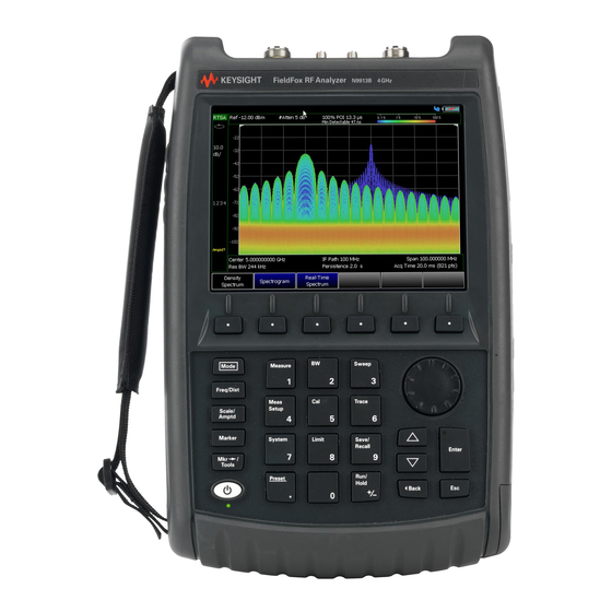
B-Series FieldFox Analyzers
- User's Guide (Unabridged)
This manual provides documentation for the
following models:
N9913B, N9914B, N9915B, N9916B,
N9917B, N9918B
N9933B, N9934B, N9935B, N9936B,
N9937B, N9938B
N9950B, N9951B, N9952B, N9953B
N9960B, N9961B, N9962B, N9963B
This is the unabridged version of the abridged N9938-90003 User's Guide that is available in printed format. The abridged
User's Guide can be found here:
https://www.keysight.com/us/en/assets/9018-04841/usermanuals/9018-04841.pdf
User's Guide (Unabridged)
)
Advertisement
Chapters

Related Manuals for Keysight FieldFox B Series


Summary of Contents for Keysight FieldFox B Series
- Page 1 Keysight B-Series FieldFox Analyzers - User's Guide (Unabridged) This manual provides documentation for the following models: N9913B, N9914B, N9915B, N9916B, N9917B, N9918B N9933B, N9934B, N9935B, N9936B, N9937B, N9938B N9950B, N9951B, N9952B, N9953B N9960B, N9961B, N9962B, N9963B This is the unabridged version of the abridged N9938-90003 User's Guide that is available in printed format. The abridged User’s Guide can be found here:...
- Page 2 Notices DOCUMENT THAT CONFLICT WITH writing elsewhere in the EULA. THESE TERMS, THE WARRANTY Keysight shall be under no obligation TERMS IN THE SEPARATE to update, revise or otherwise modify © Keysight Technologies, Inc. the Software. With respect to any AGREEMENT WILL CONTROL.
- Page 3 URLs, according to the name of your product: http://www.keysight.com/find/fieldfox To receive the latest updates by email, subscribe to Keysight Email Updates at the following URL: http://www.keysight.com/find/MyKeysight Information on preventing instrument damage can be found at: https//www.keysight.com/find/PreventingInstrumentRepair...
- Page 4 For customers upgrading FieldFox firmware, the following is a list of changes from the previous release: — SA mode – — Added: Time Difference of Arrival (TDoA) – (Option 390); Directional Finding capability when using Pathwave's PC-based S9910A Keysight Signal Measurement Software (KSMS). Refer to https://www.keysight.com/us/en/products/software.html. — Electromagnetic Field Measurements (EMF) - (Option 358) ——Added: Manual EMF measurements (with corrections) feature...
- Page 5 If you do not have access to the Internet, please contact your Keysight field engineer. In any correspondence or telephone conversation, refer to the Keysight product by its model number and full serial number. With this information, the Keysight representative can determine whether your product is still within its warranty period.
- Page 7 Resolution (Number of Data Points) ......... 56 Keysight N9938-90006 User’s Guide...
- Page 8 Mixed-Mode S-Parameters ..........92 Keysight N9938-90006 User’s Guide...
- Page 9 Gating ..............122 Keysight N9938-90006 User’s Guide...
-
Page 10: Time Domain - Option
Check for Compressed Measurements ........160 Keysight N9938-90006 User’s Guide... - Page 11 Spectrum Emission Mask (SEM) — (SA Mode Only) ....... 240 Keysight N9938-90006 User’s Guide...
- Page 12 Recording Configuration ..........284 Keysight N9938-90006 User’s Guide...
- Page 13 Alignments ............334 Keysight N9938-90006 User’s Guide...
- Page 14 Option 360 Setup Procedure ..........427 Keysight N9938-90006 User’s Guide...
- Page 15 Miscellaneous Mapping Errors..........517 Keysight N9938-90006 User’s Guide...
- Page 16 Attenuation ............556 Keysight N9938-90006 User’s Guide...
- Page 17 How to select Pulse Measurement Mode ........589 Keysight N9938-90006 User’s Guide...
- Page 18 Limitations .............615 Keysight N9938-90006 User’s Guide...
- Page 19 Calibration Wizard ............710 Keysight N9938-90006 User’s Guide...
- Page 20 How to Use Scale Settings ..........752 Averaging (CAT, NA, Power Meter, Channel Scanner, and Pulse Measurement Modes Only) Keysight N9938-90006 User’s Guide...
- Page 21 CAT/NA ............. . . 781 Keysight N9938-90006 User’s Guide...
- Page 22 Service Diagnostics—Battery Screen ........824 Keysight N9938-90006 User’s Guide...
- Page 23 ............... . 856 Keysight N9938-90006 User’s Guide...
- Page 24 ............... . .872 F:. Keysight Software End-User Licensing Agreement (EULA) .
- Page 25 Keysight Handheld Analyzers N99xxB User’s Guide 1 Overview Models and Options Table 1-1 Models Model Max Freq Description (GHz) N9913B Vector Network Analyzer AND Spectrum RF Analyzer N9914B Vector Network Analyzer AND Spectrum RF Analyzer N9915B Vector Network Analyzer AND Spectrum Microwave Analyzer...
- Page 26 17 mm torque wrench N9910X-887 Replacement Fan Kit Although not supplied, a USB keyboard and mouse CAN be used with the FieldFox. To see a complete list of accessories that are available for the FieldFox, please visit: http://www.keysight.com/find/fieldfox. Keysight N9938-90006 User’s Guide...
- Page 27 FieldFox MW VNA/SA Service Guide (keysight.com) — Firmware Updates – Check to see if you have the latest FieldFox firmware. FieldFox Current Firmware (New CPU) | Keysight Conventions that are used in the Manual — Hardkey indicates a front panel button. The functionality of these buttons does not change.
- Page 28 Denotes a hazard. It calls attention to a procedure which, if not correctly performed or adhered to, could result in injury or loss of life. Do not proceed beyond a warning note until the indicated conditions are fully understood and met. Keysight N9938-90006 User’s Guide...
- Page 29 FieldFox. Various AC power cables are available from Keysight that are unique to specific geographic areas. You can order additional AC power cables that are correct for use in different areas. For the power cord part number information please visit: http://www.keysight.com/find/fieldfox...
- Page 30 Chapter 34, “Working with the Lithium-Ion Battery.” Battery charge status is viewable: — In the upper-right corner of the screen. — On the Battery screen. To access the screen, select System > Service Diagnostics > Battery. Keysight N9938-90006 User’s Guide...
- Page 31 — To turn power ON, briefly press the power button. Boot-up takes about 1 minute. — To switch to Standby mode (low battery drain), briefly press the power button. See the Note above concerning Stand By. Keysight N9938-90006 User’s Guide...
- Page 32 FieldFox. Do NOT store the FieldFox in the soft-case while powered ON or in Standby mode. How to monitor the internal FieldFox temperature: — Press System > Service Diagnostics. — Then Internal Temperatures. Keysight N9938-90006 User’s Guide...
- Page 33 For RTSA mode (where duty cycling is not possible), you will see the following messages displayed for ~3 seconds: "Entering Auto Protect mode for thermal management" Later if the temperatures are reduced: "Temperatures reduced, exiting Automatic Protect Mode" Keysight N9938-90006 User’s Guide...
- Page 34 2-2). See also, Table 2-1 on page When you exit the Auto Protect (Maximum) Threshold control mode, the following message is displayed: "Temperatures reduced, exiting Maximum Auto Protect mode" Figure 2-2 Exiting Maximum Auto Protect mode message—(~62.5°C) Keysight N9938-90006 User’s Guide...
- Page 35 ~75.5°C. At above ~78°C, High-Temperature Shut down will engage and turn OFF the FieldFox. Refer to Figure 2-3. See also, Table 2-1 on page Figure 2-3 Shutdown Warning message—(above ~77°C) - (RTSA Mode Only!) Keysight N9938-90006 User’s Guide...
- Page 36 Avoid Overpowering the FieldFox The FieldFox can be damaged with too much power or voltage applied. Exceeding the maximum RF power levels shown below will cause an ADC Over Range message to appear on the screen. Keysight N9938-90006 User’s Guide...
- Page 37 FieldFox, may damage the instrument input circuitry. To avoid such damage, it is recommended to dissipate any static charges by temporarily attaching a short to the cable or antenna prior to attaching to the FieldFox. Keysight N9938-90006 User’s Guide...
- Page 38 Preparing for Initial Use of Your New FieldFox Take the FieldFox Tour Take the FieldFox Tour Front Panel Keysight N9938-90006 User’s Guide...
- Page 39 Displays a sub-menu for marker functions “All about Markers” page 726 Exits and closes the Active Entry dialog box or clears the character input Save/Recall Saves the current trace or recalls saved data from memory “Saving Recalling Files” on page 804 Keysight N9938-90006 User’s Guide...
- Page 40 Alternative color modes exist that maximize viewing in direct sunlight conditions, as well as other conditions such as nighttime work. Clean the Transflective screen with gentle and minimal wiping using Isopropyl alcohol applied to a lint-free cloth. Keysight N9938-90006 User’s Guide...
- Page 41 N9910X-825. Other GPS antennas can also be used. Ref In SMA (f) connector for use with Frequency Reference Source and External “Frequency Reference Trig In Trigger Input signal. Source” on page 789. “Triggering” on Maximum: 5.5 VDC. page 195 Keysight N9938-90006 User’s Guide...
- Page 42 Two standard USB connectors used to connect a power sensor for Power “Saving and Recalling Meter Mode. Also used to save files to a USB flash drive. Files” on page 804 IMPORTANT! It is recommended that only USB certified cables are used with the FieldFox. Keysight N9938-90006 User’s Guide...
- Page 43 DC Voltage Source for use with external DC Bias. “Variable Voltage Source (Opt. 309)” on page 790 DC power connector used to connect to the AC/DC adapter. Maximum: 19 “Internal Charging with VDC, 4 ADC. the AC/DC Adapter ” on page 825 Keysight N9938-90006 User’s Guide...
- Page 44 Data / Mem Display (CAT and NA) “All about Trace Math” Step / FFT (SA) on page 750 “Resolution Bandwidth (Res BW)” on page 185 Resolution Setting Mode dependent Measurement Start Freq or Distance Mode dependent Keysight N9938-90006 User’s Guide...
- Page 45 “Date and Time” on page 776 Marker Readout “All about Markers” on page 726 Battery Status “Viewing the Battery Charge Status” on page 823 Measurement Type (CAT and NA) Acquisition Mode dependent Reference Position Mode dependent Keysight N9938-90006 User’s Guide...
- Page 46 Select Frequency multipliers as follows: — Gigahertz (1e9 Hertz) — Megahertz (1e6 Hertz) — Kilohertz (1e3 Hertz) — Hertz Select Time multipliers as follows: — Seconds — milliseconds (1e–3) — microseconds (1e–6) — nanoseconds (1e–9) — picoseconds (1e-12) Keysight N9938-90006 User’s Guide...
- Page 47 In addition, a dirty or damaged connector can destroy connectors that are mated to it. For this reason, NEVER use a damaged connector. See also http://na.support.keysight.com/pna/connectorcare/Connector_Care.htm Keysight N9938-90006 User’s Guide...
- Page 48 Preparing for Initial Use of Your New FieldFox Connector Care Keysight N9938-90006 User’s Guide...
-
Page 49: Table Of Contents
Keysight Handheld Analyzers N99xxB User’s Guide CAT (Cable and Antenna Test) Mode CAT Mode is typically used to test an entire transmission system, from the transmitter to the antenna. This process is sometimes referred to as Line Sweeping. CAT Mode is similar to NA (Network Analyzer) Mode. - Page 50 “All about Limit Lines” on page 741 “All about Trace Math” on page 750 Learn more in Making 75Ω (ohm) Measurements in the Supplemental Online Help at: https://www.keysight.com/us/en/lib/resources/service-manuals/keysight -fieldfox-library-help-and-manuals-2153870.html (Keysight FieldFox Library, Help and Manuals – FieldFox Online Supplemental Help). Keysight N9938-90006 User’s Guide...
-
Page 51: Measurement Selection
MINUS the amount of energy that is reflected. The higher the trace is on the screen, the more energy being reflected back to the FieldFox. Learn how to measure Return Loss on “Return Loss Measurements” on page Keysight N9938-90006 User’s Guide... -
Page 52: Quick Settings Table
— Then press Edit. The current setting changes to yellow. — Some settings require you to press a softkey to change the value. Otherwise, use the numeric keypad, arrows, or rotary knob to change the value. Keysight N9938-90006 User’s Guide... -
Page 53: Frequency Range
Adjust the Y-axis scale to see the relevant portions of the data trace. The Y-axis is divided into 10 graticules. This setting can be changed at any time without affecting calibration accuracy. How to set Scale — Press Scale / Amptd. Keysight N9938-90006 User’s Guide... -
Page 54: Averaging
When the counter reaches the specified count, then a ‘running average’ of the last N sweeps is displayed. Average Count = 1 means there is NO averaging. Keysight N9938-90006 User’s Guide... -
Page 55: Smoothing
Use Single to conserve battery power or to allow you to save or analyze a specific measurement trace. This setting can be changed at any time without affecting calibration accuracy. How to set Single or Continuous — Press Sweep 3. Keysight N9938-90006 User’s Guide... -
Page 56: Resolution (Number Of Data Points)
The increase will not be exactly the amount that you enter, as the actual sweep time is the composite of many factors. Measurement speed specifications do NOT apply in Temperature Control Mode. Learn more in Chapter 1, “Overview.” Keysight N9938-90006 User’s Guide... -
Page 57: Output Power
NOT be achieved, a warning message and beep occurs. To achieve a flattened output power, reduce the power level or stop frequency. — Then press Power Level — Then enter a value using the numeric keypad, the arrows, or the rotary knob. — Press Enter. Keysight N9938-90006 User’s Guide... -
Page 58: Interference Rejection
Coupled Freq ON - Both the Return Loss and DTF traces have the same frequency range settings. — Coupled Freq OFF (default setting) - Both traces are allowed to have individual frequency range settings. When set to OFF: Keysight N9938-90006 User’s Guide... -
Page 59: Return Loss Measurements
— Disconnect the jumper cable or DUT and press Cal 5 then follow the calibration prompts. — Reconnect the jumper cable or DUT. — The return loss trace is displayed on the FieldFox screen. Keysight N9938-90006 User’s Guide... -
Page 60: 1-Port Cable Loss Measurements
7. Press Cal 5, then Mechanical Cal. 8. Follow the prompts to perform calibration at the end of the jumper cable or adapter. Learn more about Calibration in “How to Perform a Calibration” on page 127 Keysight N9938-90006 User’s Guide... -
Page 61: 2-Port Insertion Loss Measurements
To obtain complex data, either as real/imaginary or magnitude/phase pairs, use NA mode. 2-port Insertion Loss measurements are generally more accurate than 1-port Cable Loss measurements. Keysight N9938-90006 User’s Guide... - Page 62 When measuring very long lengths of cable, it may be necessary to increase the sweep time. Learn how on page 56. Learn how in the Supplemental Online Help at: https://www.keysight.com/us/en/lib/resources/service-manuals/keysight-fi eldfox-library-help-and-manuals-2153870.html (via Keysight FieldFox Library, Help and Manuals – FieldFox Online Supplemental Help). Keysight N9938-90006 User’s Guide...
- Page 63 Keysight Handheld Analyzers N99xxB User’s Guide DTF (Distance to Fault) Measurements CAT Mode Distance to Fault (DTF) measurements are generally used to locate problems, or faults, in a length of cable or transmission line. In this chapter, the cable to be tested is referred to as the DUT (Device Under Test).
- Page 64 “How to Perform a Calibration” on page 127. 7. Disconnect any components or antenna that should NOT be measured and connect a LOAD at the end of the DUT. 8. Press Meas Setup 4 then DTF Cable Specifications. Keysight N9938-90006 User’s Guide...
- Page 65 10. Connect the start end of the DUT to the FieldFox. 11. Press Meas Setup 4 then Settings then Next Page. If the Alias-free Range setting is False, then you may see Alias faults on the screen. Learn more page Keysight N9938-90006 User’s Guide...
- Page 66 Faults are displayed on the Y-axis in return loss format, expressed as a positive number in dB. — DTF (VSWR) Faults are displayed on the Y-axis in SWR. Learn more about SWR at the FieldFox Supplemental Online Help at: https://www.keysight.com/us/en/lib/resources/service-manuals/k Keysight N9938-90006 User’s Guide...
- Page 67 Freq Mode 2. Choose one of the following: — Lowpass The frequency range of a DTF measurement is set automatically based on the Start and Stop Distances. Use Lowpass mode when the DUT is a cable ONLY. Keysight N9938-90006 User’s Guide...
-
Page 68: Coupled Frequency
Coupled Frequency When a Return Loss & DTF measurement is present, this setting allows you to have different frequency ranges for each measurement. Learn more in “Coupled Frequency” on page Keysight N9938-90006 User’s Guide... -
Page 69: Cable (Correction) Specifications
Cable Loss and Velocity factor can be entered using one of the following methods: — Manually enter cable loss and velocity factor for the measurement. — Select or create a cable file which contains the cable loss and velocity factor. With a DTF measurement present: Keysight N9938-90006 User’s Guide... - Page 70 “How the Freq/Loss pairs are applied” on page 71 below. 5. Optionally choose from the following: — Previous / Next Page Quickly scrolls through pages of Freq/Loss data. — Add Data Add a blank Freq/Loss pair to the table, — Delete/Clear then: Keysight N9938-90006 User’s Guide...
- Page 71 When the cable file contains two or more Freq/Loss pairs, the Loss value that is used is interpolated from the Freq/Loss pairs and the DTF center frequency. For example, using a cable file with the following Freq/Loss pairs: 1 GHz: 0.1 dB/m 2 GHz: 0.2 dB/m Keysight N9938-90006 User’s Guide...
-
Page 72: Window Settings
(Default setting) — Medium – Compromise between Minimum and Maximum window settings. — Minimum – Best Response Resolution, providing the ability to resolve between two closely-spaced responses. 5. Then press Done Edit. 6. Again press Done. Keysight N9938-90006 User’s Guide... -
Page 73: Dtf Units
An alias fault is not a true device response. An alias fault appears because of the method used to convert frequency to time. On the DTF Settings page (above) the c - Alias-free Range = Off setting indicates alias images MAY appear on the screen. Keysight N9938-90006 User’s Guide... - Page 74 FieldFox. Re-reflections are measured at the FieldFox as mirror images of the original faults. The largest fault is the open end of the cable. To avoid confusion, set the Stop distance shortly after that fault. Keysight N9938-90006 User’s Guide...
- Page 75 Keysight Handheld Analyzers N99xxB User’s Guide TDR (Time Domain Reflectometry) - Option 215 CAT Mode Time Domain Reflectometry (TDR) measurements are generally used to locate problems, and identify the type of problem, in a length of cable or transmission line.
- Page 76 “How to Perform a Calibration” on page 127. 7. Disconnect any components or antenna that should NOT be measured and connect a LOAD at the end of the DUT. 8. Press Meas Setup 4 then DTF Cable Specifications. Keysight N9938-90006 User’s Guide...
-
Page 77: Tdr (Time Domain Reflectometry) - Option 215
10. Connect the start end of the DUT to the FieldFox. 11. Press Meas Setup 4 then Settings then Next Page. If the Alias-free Range setting is Off, then you may see Alias faults on the screen. Learn more in “About Alias Faults” on page 86 Keysight N9938-90006 User’s Guide... -
Page 78: Tdr Measurement (Format)
Then press Enter or select a suffix if available. — Other settings require you to press Edit, then press a softkey to change the value. — When finished changing a value, press Done Edit. Keysight N9938-90006 User’s Guide... -
Page 79: Tdr Start And Stop Distance
Enter a value between the start distance and 5 km (or 16,404 ft.) using the numeric keypad, the arrows, or the rotary knob, then Enter. TDR Sweep This setting allows you to choose the method by which the Stop Frequency and Resolution are set. Keysight N9938-90006 User’s Guide... -
Page 80: Frequency Mode
Start and Stop Distances. Use Lowpass mode when the DUT is a cable ONLY. — Bandpass This setting changes the measurement to DTF. Bandpass is NOT ALLOWED with TDR because the DC component is required for TDR measurements. Keysight N9938-90006 User’s Guide... -
Page 81: Cable (Correction) Specifications
— Manually enter cable loss and velocity factor for the measurement. — Select or create a cable file which contains the cable loss and velocity factor. With a TDR measurement present: — Press Meas Setup 4. Keysight N9938-90006 User’s Guide... - Page 82 Previous / Next Page Quickly scrolls through pages of Freq/Loss data. — Add Data Add a blank Freq/Loss pair to the table, — Delete/Clear then: — Delete Row Remove the selected Freq/Loss pair from the table. Keysight N9938-90006 User’s Guide...
- Page 83 The center frequency for the measurement is determined from the calculated (Stop – Start) frequency values (seen on the second page of TDR Settings): Calculated Start = 2.0 MHz Calculated Stop = 3.598 GHz Center Freq = 1.80 GHz Keysight N9938-90006 User’s Guide...
-
Page 84: Window Settings
(Default setting) — Medium – Compromise between Min and Max window settings. — Minimum – Best Response Resolution, providing the ability to resolve between two closely-spaced responses. — Then press Done Edit. — Again press Done. Keysight N9938-90006 User’s Guide... -
Page 85: Tdr Units
The TDR Units setting is also available on the TDR Settings table. Calculated TDR values Press Next Page on the TDR Settings Table to view the following calculated Values noted on the FieldFox screen with c - <setting> Keysight N9938-90006 User’s Guide... -
Page 86: About Alias Faults
A true fault response will not move in distance. That is, if a true fault is present at 10.3 meters, changing the stop distance from 15 m to 20 m will not move the fault; the fault will remain at 10.3 meters. However, an alias response will appear to move. Keysight N9938-90006 User’s Guide... -
Page 87: How To Prevent Undersampling
To prevent undersampling, set TDR Sweep to Cable. If undersampling still occurs, set TDR Sweep to Auto. Then set Auto Max Frequency to a lower value. Manually increase the Resolution so that the Start Frequency setting is less than about 500 kHz. Keysight N9938-90006 User’s Guide... - Page 88 TDR (Time Domain Reflectometry) - Option 215 TDR Measurement Settings Keysight N9938-90006 User’s Guide...
- Page 89 Keysight Handheld Analyzers N99xxB User’s Guide 6 NA (Network Analyzer) Mode Learn more about NA Mode measurements in the FieldFox Supplemental Online Help: https://www.keysight.com/us/en/lib/resources/service-manuals/keysight-fi eldfox-library-help-and-manuals-2153870.html (Keysight FieldFox Library, Help and Manuals – FieldFox Online Supplemental Help). In this Chapter “About S-parameters” on page 91 “Mixed-Mode S-Parameters”...
- Page 90 “All about Limit Lines” on page 741 “All about Trace Math” on page 750 Learn how to make 75Ω (ohm) Measurements in the Supplemental Online Help: https://www.keysight.com/us/en/lib/resources/servic e-manuals/keysight-fieldfox-library-help-and-manua ls-2153870.html (Keysight FieldFox Library, Help and Manuals – FieldFox Online Supplemental Help). Keysight N9938-90006 User’s Guide...
-
Page 91: About S-Parameters
When the source comes from port 2, the measurement is said to be in the reverse direction. S11 and S22 reflection measurements are used to measure the amount of reflections off the corresponding DUT port. Low reflections means there is a good impedance match between the source and DUT. Keysight N9938-90006 User’s Guide... -
Page 92: Mixed-Mode S-Parameters
Because the FieldFox has only two test ports, only reflection measurements are available. Connect the balanced input or output of your DUT to the FieldFox ports 1 and 2 For highest accuracy, a Full 2-port calibration is required. Keysight N9938-90006 User’s Guide... -
Page 93: Parameter Conversion
(Y). Then choose from the following for either: ——Auto The displayed S-parameter is converted to the appropriate Z or Y parameter: Refl for S11 and S22; Trans for S21 and S12. When the S-parameter is changed, the appropriate conversion changes automatically. Keysight N9938-90006 User’s Guide... -
Page 94: Receiver Measurements
Select when measuring transmission at B receiver. —Port 2 Select when measuring reverse transmission at A receiver. Learn more about Raw Receiver Measurements at the FieldFox Supplemental Online Help: https://www.keysight.com/us/en/lib/resources/service-manuals/keysight-fi eldfox-library-help-and-manuals-2153870.html (Keysight FieldFox Library, Help and Manuals – FieldFox Online Supplemental Help). Keysight N9938-90006 User’s Guide... -
Page 95: Multi-Trace Configurations
IMPORTANT! For CAT and NA modes, limit lines do not apply where F1 = F2. — By default, a marker is created on ALL traces. However, they can be created individually by disabling Coupled Markers. Learn more in “Coupled Markers (NA Mode)” on page 729. Keysight N9938-90006 User’s Guide... -
Page 96: Quick Settings
Both CAT and NA Modes allow you to view and change most relevant settings from a single location. All of these settings are discussed in this chapter and, unless otherwise noted, ALL of these settings can also be made using the standard softkey menus. Keysight N9938-90006 User’s Guide... -
Page 97: Calibration Settings
Nearest (NA Mode Only)” on page 144. How to view and change Calibration Settings — Press Meas Setup 4. — Then Calibration Settings — Make these settings in the same manner as Quick Settings in the previous section. Keysight N9938-90006 User’s Guide... -
Page 98: Format
— Learn more about Group Delay measurements at the FieldFox Supplemental Online Help: https://www.keysight.com/us/en/lib/resources/service-m anuals/keysight-fieldfox-library-help-and-manuals-2153 870.html. — Real Displays only the real (resistive) portion of the measured complex data. The Y-axis is Unitless. Often used for Time Domain measurements. Keysight N9938-90006 User’s Guide... -
Page 99: Frequency Range
Abbreviations” on page Scale Settings Adjust the Y-axis scale to see the relevant portions of the data trace. The Y-axis is divided into 10 graticules. This setting can be changed at any time without affecting calibration accuracy. Keysight N9938-90006 User’s Guide... -
Page 100: Magnitude Offset
Real (unitless), the conversion from dB is performed and the correct amount of offset is implemented. The Magnitude offset setting affects only the active trace. How to set Magnitude Offset 1. Press Scale / Amptd 2. Then More Keysight N9938-90006 User’s Guide... -
Page 101: Electrical Delay
360°. Use this feature in the following ways: Improve the display of a phase measurement. This is similar to the way you would change the acquisition in an amplitude measurement. Change the phase response to center or the response on the screen. Keysight N9938-90006 User’s Guide... -
Page 102: Averaging
On subsequent sweeps, averaging restarts by measuring each data point again <n> times. The average counter is not updated because data is not displayed until all the averages have been applied. Keysight N9938-90006 User’s Guide... -
Page 103: If Bandwidth
This setting determines whether the FieldFox sweeps continuously or only once each time the Single button is pressed. Use Single to conserve battery power or to allow you to save or analyze a specific measurement trace. Keysight N9938-90006 User’s Guide... -
Page 104: Resolution (Number Of Data Points)
The fastest possible sweep time is always used as the default setting. Use the Min Swp Time setting to slow the sweep time when measuring long lengths of cable. Learn more at the FieldFox Supplemental Online Help: https://www.keysight.com/us/en/lib/resources/service-manuals/keysight-fi eldfox-library-help-and-manuals-2153870.html. Keysight N9938-90006 User’s Guide... -
Page 105: Triggering (Na)
— A sweep can NOT be initiated by an external signal while a sweep is in progress. — A sweep can NOT be initiated by an external signal when in HOLD mode. Learn more about HOLD mode in. Keysight N9938-90006 User’s Guide... - Page 106 — If the FieldFox is in a state requiring two sweeps and the user selects point mode triggering, an error "Error: Point trigger not compatible with 2-port cal." will be displayed and point mode trigger will revert to Internal trigger. Keysight N9938-90006 User’s Guide...
-
Page 107: Output Power
FLAT across the displayed FieldFox frequency span. If flattened power can NOT be achieved, a warning message and beep occurs. To achieve a flattened output power, reduce the power level or stop frequency. a. Then press Power Level Keysight N9938-90006 User’s Guide... -
Page 108: System Impedance (Z0)
— With S21 and S12 transmission measurements, the port 1 and port 2 extensions are added together. This accounts for the total transmission delay going through ports 1 and 2. Port extensions and Electrical Delay differ in the following ways: Keysight N9938-90006 User’s Guide... -
Page 109: Velocity Factor
VF = 1.0 (default setting) corresponds to wave propagation through free space (a vacuum). How to set Velocity Factor 1. Press Meas Setup 4 > Port Extensions > Velocity Factor 2. Then enter a value between 0.1 and 1 using the numeric keypad, then press Enter. Keysight N9938-90006 User’s Guide... - Page 110 732. — Big Readout - For each marker readout (1, 2, and 3), select from the following: —Marker # - Enter a number from 1 to 6 to create the marker. 1 is created by default. Keysight N9938-90006 User’s Guide...
- Page 111 Lin using the standard menu (Meas 1, Format), the setting will show on the display. But if you then use the Big Readout (A | B | OFF) setting, when B is recalled, the Lin setting will be overwritten with the original Log setting. Keysight N9938-90006 User’s Guide...
-
Page 112: Increase Dynamic Range
The results you see will depend on the performance of your DUT. With an S21 trace active: 1. With RF OUT (port-2) open, press Trace 6 then Math and Memory then Data->Mem 2. Re-connect the DUT. 3. Press Data Math then Data-Mem Keysight N9938-90006 User’s Guide... - Page 113 Keysight Handheld Analyzers N99xxB User’s Guide Time Domain – Option 010 With NA Mode, Time Domain (Opt 010), frequency information is used to calculate and display measurements with time as the horizontal display axis. The response values appear separated in time allowing a different perspective of the test device's performance and limitations.
- Page 114 Time Domain – Option 010 Gating Settings “Start, Stop, Center, and Span Gate Times” on page 123 “Gating Type” on page 123 Keysight N9938-90006 User’s Guide...
- Page 115 “Gating” on page 122. Markers that are created on a Time Domain trace can be used to pinpoint the distance of the mismatch from the reference plane. For more information on Time Domain theory, see https://www.keysight.com/us/en/assets/7018-01451/application-notes/598 9-5723.pdf. Keysight N9938-90006 User’s Guide...
-
Page 116: Time Domain (Transform) Settings
Inverse Fourier Transform (IFT), time is calculated. Select the frequency range from which Time Domain measurements are calculated. Increasing the data points will improve measurement resolution. However, more data points will usually result in slower sweep updates. Set frequency range and points before selecting Stimulus Mode. Keysight N9938-90006 User’s Guide... -
Page 117: Stimulus (Mode)
How to set Start and Stop time — Press Measure Setup 4 — Then Transform — Then Transform Start Stop Keysight N9938-90006 User’s Guide... -
Page 118: Distance Units
Time Domain response. The Window setting reduces the abruptness of the frequency domain transitions. This causes you to make a trade off in the Time Domain response. Keysight N9938-90006 User’s Guide... -
Page 119: Line Loss And Velocity Factor
Line Loss and Velocity Factor By default, the FieldFox does NOT correct Time Domain measurements to account for the inherent loss of a cable. However, to make more accurate measurements, Line Loss and Velocity Factor should be considered. Keysight N9938-90006 User’s Guide... -
Page 120: Data Chain
— Standard – The normal FieldFox data processing chain. Transform calculations are performed AFTER error correction and trace math. — 8510 – The data processing chain used by the Keysight 8510 network analyzer. Transform calculations are performed BEFORE error correction and trace math. -
Page 121: Trace Settings
Enable Gating for the specific trace. — Select the trace. — Press Measure Setup 4 — Then Transform — Then choose from: — Gating On Trace displays Time Domain data. — Gating Off Trace displays frequency domain data. Keysight N9938-90006 User’s Guide... - Page 122 The following image shows how gating can affect measurement results. All 4 traces show the same S11 measurement. Trace 1 shows the frequency response without gating enabled. Trace 2 shows the transform response without gating enabled. Trace 3 shows the transform response with gating enabled. Keysight N9938-90006 User’s Guide...
-
Page 123: Gating Type
The gate start and stop flags on the display point toward the part of the trace you want to keep. Choose from the following: — Bandpass KEEPS the responses within the Gating Start and Stop times. — Notch REMOVES the responses within the Gating Start and Stop times. Keysight N9938-90006 User’s Guide... - Page 124 If you specify a gate span that is smaller than the minimum span, the response will show the following effects: — distorted gate shape that has no passband — distorted shape — incorrect indications of start and stop times — may have increased sidelobe levels. Keysight N9938-90006 User’s Guide...
-
Page 125: Chapter 8, "Calibration For Na, Cat, And Vvm Modes
Keysight Handheld Analyzers N99xxB User’s Guide Calibration for NA, CAT, and VVM Modes Calibration removes the systematic errors that are associated with measurements in NA, CAT, and VVM Modes. Key presses are identical in all of these Modes. In this Chapter “Why and When to Calibrate”... -
Page 126: Why And When To Calibrate
DUT port during some measurements. — SHORT and OPEN standards both cause 100% of an RF signal to be reflected. The difference between these two standards is what happens to the phase of the reflected signal, which is beyond the Keysight N9938-90006 User’s Guide... -
Page 127: Calready
When performing a calibration that contains a large number of points (5000 to 10,001 points) be aware that the calibration progress bar may not move for 2 or 3 minutes during the calibration process. In CAT, NA, or VVM Mode, press Cal 5. Keysight N9938-90006 User’s Guide... - Page 128 You can ignore the “Source Unleveled” error, or to avoid the error, select either High power or –15 dBm before calibrating. Learn more about setting Output Power in “Output Power” on page Keysight N9938-90006 User’s Guide...
-
Page 129: Mechanical Cal
Mechanical Calibration is performed using discrete standards from a Cal Kit. Several Cal Kit definitions are built into the FieldFox. To learn about Cal Kit definitions, refer to the Application Note, “Specifying Calibration Standards and Kits for Keysight Vector Network Analyzers,” available online at https://www.keysight.com/us/en/assets/7018-01375/application-notes/598 9-4840.pdf. - Page 130 “Calibration Type” on page 136. To select a different Cal Type: — Press Change Cal Type. — Then using the arrows or rotary knob, select a Cal Type, — Then press Select and Finish. Begin Calibration Keysight N9938-90006 User’s Guide...
-
Page 131: Ecal
Cal Kit covers the frequency range of the measurement. You can verify the frequency range of your Cal Kit at: www.keysight.com/find/fieldfoxsupport. Click Cal Kits. 2. Follow the Cal Wizard prompts. Connect the specified standard at the point where the DUT will be connected, then press Measure. - Page 132 Mechanical Cal Setup page of the CalWizard. However, a User Characterization can NOT be PERFORMED using the FieldFox. It must be performed using a bench top Keysight VNA, such as the PNA or ENA. Learn more about User Characterization at the PNA Help website: http://na.support.keysight.com/pna/help/latest/S3_Cals/ECal_User_Charact...
- Page 133 If the frequency is adjusted outside of the set of points calibrated the error correction is turned off and the following message is displayed: "Error correction disabled. Stimulus outside calibrated range." Keysight N9938-90006 User’s Guide...
-
Page 134: Simple Response Cals
SHORT to the port 1 reference plane. When Simple Response Cals are performed, the source match and reflection tracking terms from CalReady are updated by the measured Short or Open that is used during the calibration. Keysight N9938-90006 User’s Guide... - Page 135 User Cal (Ex: Response Cal) is correcting ONLY the appropriate measurement. For example, when an Open Response Cal on Port 2 is performed, CAL ON U is shown for an S22 measurement only. Keysight N9938-90006 User’s Guide...
-
Page 136: View Cal
S-parameters. However, there may be times when you may want a little more accuracy or a little faster sweep time. The following information can help you learn about the various calibration choices. Keysight N9938-90006 User’s Guide... - Page 137 1-Port (OSL) DUT: No restrictions S-parameters Corrected: S11 or S22 Standards: OPEN, SHORT, LOAD Sweeps in ONE direction. FULL 2-Port (May require an option) Most comprehensive calibration. Corrects all S-parameters DUT: Non-Insertable or Insertable Keysight N9938-90006 User’s Guide...
- Page 138 Standards: Thru, Reflect, Line or variations of these. A TRL Cal Kit MUST be selected to see this Cal Type Sweeps in BOTH directions. Learn more about TRL Calibration in the Supplemental Online Help: https://www.keysight.com/us/en/lib/resources/service-manuals/keysigh t-fieldfox-library-help-and-manuals-2153870.html Keysight N9938-90006 User’s Guide...
- Page 139 (default) Omits the Isolation step 4. Then <Back 5. Configure and perform the calibration as usual. At the first step of the Cal you will be prompted to connect a Load standard to one or both test ports. Keysight N9938-90006 User’s Guide...
- Page 140 Otherwise, an error message will appear during the ‘Calculating Steps’ portion of the calibration. Waveguide Cal Kits Keysight sells two waveguide Cal Kit series: the premium 11644A series and the economy N9911X series. Both are available online at www.Keysight.com Effective Velocity Factor Velocity factor is the speed at which an electromagnetic signal passes through the transmission medium relative to the speed of light.
-
Page 141: Enhanced Response Optimization
CalReady, this setting optimizes the calibration based on the type of DUT being measured. See also: CalReady Properties in “CalReady” on page 127. This setting does NOT survive Preset. 1. Press Cal 5 > More Enh.Response > 2. Then choose from: Keysight N9938-90006 User’s Guide... -
Page 142: Interpolation
(1-port or 2-port). To apply a Cal that was performed in a different mode, press Cal 5 then select User Cal Keysight N9938-90006 User’s Guide... -
Page 143: Save The Calibration
Data & Memory. 5. Press Cal 5 > More 6. Select a CalReady Cal to compare with the current setting. 7. Press Esc to exit the cal menu. 8. View the differences in the two traces. Keysight N9938-90006 User’s Guide... -
Page 144: Apply Nearest (Na Mode Only)
— Higher than 30 dB indicates that you should recalibrate. Verifying Phase Accuracy — Connect a LOAD standard at the calibration reference plane (where calibration standards were connected). — In NA Mode, select a S11 Reflection with Polar or Smith Chart format. Keysight N9938-90006 User’s Guide... -
Page 145: Test The Jumper Cable
— If the measurement trace is relatively stable, the jumper cable is of good quality. — If you observe significant movement in the peaks of the measurement trace when moving the cable (>5 dB), the jumper cable may need to be replaced. Keysight N9938-90006 User’s Guide... - Page 146 — When the temperature changes more than about 10°F (5°C) — When the connection to the DUT requires a different jumper cable or adapters. — When any of the following measurement settings change: Frequency Range, Power Level, IF BW, and Resolution. Keysight N9938-90006 User’s Guide...
- Page 147 Keysight Handheld Analyzers N99xxB User’s Guide SA (Spectrum Analyzer) Mode (Option 233–Mixed Analyzers) To better reflect the enhancements implemented during the alignment > process, for firmware versions A.10.15 “IF Flatness Alignment” is now referred to as “Channel Equalization” or “Channel Equalization Alignment”...
- Page 148 “Very Long Sweep Times” on page 193 “Zero Span Measurements” on page 193 “Triggering” on page 195 “FFT Gating (Opt 238)” on page 199 “Single / Continuous / Restart” on page 201 “Points ” on page 201 Keysight N9938-90006 User’s Guide...
- Page 149 Streaming, SA Mode Only)” on page 247 “Effective Isotropic Radiated Power (EIRP) – (SA Mode Only)” on page 250 See Also Interference Analyzer: “Spectrogram Display (SA Option)” on page 530 “Waterfall Display” on page 533 “Record/Playback (SA Option)” on page 535 Keysight N9938-90006 User’s Guide...
- Page 150 SA (Spectrum Analyzer) Mode (Option 233–Mixed Analyzers) Optional Settings: “All about Markers” on page 726 “All about Limit Lines” on page 741 “Saving and Recalling Files” on page 804 Keysight N9938-90006 User’s Guide...
-
Page 151: Frequency Range
762, the B Series FieldFox Configuration Guide 5992-3701EN, and to “Contacting Keysight” on page Available ONLY with Opt. 209 and while in Step sweep, SA mode allows reverse sweeps. This means the Start frequency can be higher than the Stop frequency. - Page 152 —More — Then Full Span Selects the entire frequency span of the FieldFox. The Center frequency is set automatically. When in full span, ADC dither raises the noise floor at the edges of the 120 MHz. Keysight N9938-90006 User’s Guide...
-
Page 153: Radio Standard
When a Channel Measurement is selected such as ACPR, other relevant settings will be changed such as Integration BW. Learn more about Radio Standards and Channel Measurements in “Radio Standards and Channel Measurements” on page 217. Keysight N9938-90006 User’s Guide... - Page 154 To overwrite a custom standard that is already uploaded to the FieldFox, you must first delete the *.csv file from the FieldFox, then re-upload the file that contains the standard. A predefined internal standard (such as GSM 450) can NOT be deleted from the FieldFox. Keysight N9938-90006 User’s Guide...
-
Page 155: Channel Selection
—Follow each of the above settings by entering a value using the numeric keypad or the rotary knob. —Use the arrows to increment the channel number by an amount specified by the Channel Step value (see below). — Then press Enter or Enter. Keysight N9938-90006 User’s Guide... -
Page 156: Reverse Swap
Available ONLY with Opt. 209 and while in Step sweep mode. Each press of the softkey causes the Start and Stop frequencies to swap. The Start becomes the Stop and vice versa. Learn more about Step versus FFT sweeps in “FFT Gating (Opt 238)” on page 199. Keysight N9938-90006 User’s Guide... -
Page 157: Scale And Units
(%) below or above the reference line. — Unit Refer to “How to Set Y-axis Units” on page 158. — Corrections Refer to “How to select and edit corrections for Field Strength measurements” on page 161. Keysight N9938-90006 User’s Guide... -
Page 158: External Gain
(positive for gain; negative for loss). Values less than 5 dB must be typed using the numeric keypad. Then press Enter ExtGain xx dB is shown at the top of the screen. Keysight N9938-90006 User’s Guide... -
Page 159: Attenuation Control
RF Attenuation is set manually. The default Attenuation setting is 10 dB. Enter a value between 0 to 30 dB in 5 dB steps using the numeric keypad, the arrows, or the rotary knob. Then press Enter Keysight N9938-90006 User’s Guide... -
Page 160: Preamplifier Control (Opt 235)
This indicates that the signal is in the linear region of the FieldFox receiver. — If the signal level DOES increase, then the receiver was compressed. Set the RF Attenuation value at the setting when further increases no longer result in an increase in the displayed power level. Keysight N9938-90006 User’s Guide... -
Page 161: Field Strength Measurements
Use Auto and Disabled correction for all settings. (Default = Auto). — Antenna Off – Opens a softkey menu to enable/disable a antenna and edit, save, create a new antenna factors table, recall, and set a storage device location. Keysight N9938-90006 User’s Guide... - Page 162 – Turn correction ON or OFF for this Antenna/Cable. — Edit Antenna Edit Cable– Edit an Antenna/Cable Correction table. See Using the Antenna/Cable Editor (below) for more information. — – Create a new Antenna/Cable. See Using the Antenna/Cable Editor (below) for more information. Keysight N9938-90006 User’s Guide...
-
Page 163: Using The Antenna/Cable Editor
Using the Antenna/Cable Editor The Antenna Editor and the Cable Editor menus are very similar. Both tables include header information, and a Frequency/Value table. Figure 9-2 FieldFox Antenna Editor– E–Field and H-Field Units Displayed E-Field Units H-Field Units Keysight N9938-90006 User’s Guide... - Page 164 Amplitude units will be available or not, and how to convert between them. Select None (default setting) if you just want standard Amplitude units, with a simple dB offset supplied by the correction table. This makes the correction basically identical to a Cable Keysight N9938-90006 User’s Guide...
- Page 165 Remove all Freq/Value pairs from the table and resets header information to default settings. When the table edits are complete 1. Press Done to close the Antenna/Cable Editor. 2. Press Antenna Off On > On. Keysight N9938-90006 User’s Guide...
- Page 166 — All Antenna and Cable files are saved and recalled as *.csv files, which allows them to also be read by spreadsheet programs. — The FieldFox can also read *.ANT (Antenna) files that were created from older Keysight Spectrum Analyzers. Keysight N9938-90006 User’s Guide...
-
Page 167: Source Tracking Offset And Offset Reversal
SourceFreq = Offset + RecFreq. Use to measure Upconverters. — SourceFreq = Offset - RecFreq. Use to measure Downconverters. The source sweeps in Reverse direction. Note: The Offset Freq. MUST be larger than the Receiver Stop Freq. Keysight N9938-90006 User’s Guide... -
Page 168: Tune & Listen (Am/Fm)
“How to select Tune & Listen” on page 169 “TnL AM SSB Gain” on page 169 – “Tune Frequency” on page 170 “Listen Time” on page 170 “To select Listen Time:” on page 171 “Volume Control” on page 171 Keysight N9938-90006 User’s Guide... - Page 169 – sets the gain in the IF path for TnL SSB measurements (the optimal IF path gain is automatically determined/set for regular AM and all the other demod types, but it cannot be automatically determined for AM SSB so it has to set it manually). Keysight N9938-90006 User’s Guide...
- Page 170 While Tune & Listen is actively demodulating a signal, the SA does not sweep and update the display. Listen Time sets the amount of time that the FieldFox demodulates, then stops to perform a single sweep and update the display, then again demodulates. Keysight N9938-90006 User’s Guide...
- Page 171 Listen are selected, you can choose from the following: — Press Marker > Normal — Press Mkr->/Tools > Mkr->TuneFreq – The Tune & Listen Frequency becomes the frequency of the active marker (When AM Metrics or FM Metrics are selected this softkey is inactive). Keysight N9938-90006 User’s Guide...
-
Page 172: Analog Demod
The Analog Demod measurement displays a normal SA sweeps for the display while performing audio demodulation at the carrier Frequency. See the “How to select Analog Demod (Metrics)” on page 173 setting for more information. Figure 9-5 AM DSB (Metrics) – Demodulation Spectrum Keysight N9938-90006 User’s Guide... - Page 173 (to hear the left and right channels separately on the FieldFox) you have to use the headphone jack and stereo headphones (i.e., most earbuds, headphones, etcetera support stereo). Learn more, see also Chapter 31, “System Settings.” “Audio (Volume) Control” on page 759. Keysight N9938-90006 User’s Guide...
- Page 174 (Default = 100%). If AM SSB, choose from: — SSB Top Y – Determines the Y axis voltage (0 nV to ± 100mV) of the AM SSB demodulation waveform is displayed (Default = 100 mV). Keysight N9938-90006 User’s Guide...
- Page 175 Demod View Time Freq – Toggles how the demodulated signals are displayed (Time (waveform) or Frequency (spectrum)); Default = Time). — Audio Capture Playback – Refer to “Setting the Audio Capture Playback Softkeys” on page 176. Keysight N9938-90006 User’s Guide...
- Page 176 When Analog Demod is selected, you can choose from the following: — Press Meas Setup 4 > More > Audio Capture Playback then — If you want to initiate an audio capture: Press Capture — If you want to stop an audio capture: Keysight N9938-90006 User’s Guide...
- Page 177 (single channel). — Then File Settings then — Filename – Opens the filename labeler to specify a filename. — Timestamp OFF ON – Enables/disables a timestamp label on your audio (.wav) filename. Keysight N9938-90006 User’s Guide...
- Page 178 LPF 3 dB Cutoff 300.000 Hz – When the Lowpass filter is set to Custom, sets the customized LPF 3 dB cutoff frequency for the lowpass filter (Default = 300 Hz; Minimum = 90 Hz, Maximum = 5 MHz). Keysight N9938-90006 User’s Guide...
- Page 179 (Minimum = 1 ms and Maximum = 2s; default = 100 ms). The Counter Gate softkey is not available when AM Tune & Listen, FM (narrow) Tune & Listen, or FM (wide) Tune & Listen are enabled. Refer to Figure 9-9 on page 182. Keysight N9938-90006 User’s Guide...
- Page 180 SA (Spectrum Analyzer) Mode (Option 233–Mixed Analyzers) SA Mode Settings See also, “How to use Marker Functions” on page 739. Figure 9-6 AM DSB (Metrics) – Demodulation Waveform Keysight N9938-90006 User’s Guide...
- Page 181 SA (Spectrum Analyzer) Mode (Option 233–Mixed Analyzers) SA Mode Settings Figure 9-7 FM Metrics – Demodulation Spectrum Figure 9-8 FM (Metrics) – Demodulation Waveform Keysight N9938-90006 User’s Guide...
- Page 182 SA (Spectrum Analyzer) Mode (Option 233–Mixed Analyzers) SA Mode Settings Figure 9-9 FM (Metrics) - Counter Gate and FM Demodulation Waveform Keysight N9938-90006 User’s Guide...
- Page 183 SA (Spectrum Analyzer) Mode (Option 233–Mixed Analyzers) SA Mode Settings Figure 9-10 Audio Capture with Annotation Examples Keysight N9938-90006 User’s Guide...
-
Page 184: Independent Source/Tracking Generator
Trace 4 reference trace, and therefore become relative to it. SrcN annotated on the screen. Normalize is automatically turned OFF when the frequency range or Resolution is changed. Learn more about Trace Display States in “Trace Display States (SA Mode)” on page 201. Keysight N9938-90006 User’s Guide... -
Page 185: Resolution Bandwidth (Res Bw)
Res BW is also narrowed providing increased ability to resolve signals. To change this setting from Man to Auto, press Res BW twice. 1. N995xB/6xB cannot have the Leveled value set lower than –35 dBm. Keysight N9938-90006 User’s Guide... -
Page 186: Video Bandwidth (Video Bw)
Video BW filter has reached the maximum capacity for averaging. AF RBW (Audio-Frequency Resolution BW) AF RBW - sets the audio-frequency resolution bandwidth for the selected frequency (Default = Auto). Keysight N9938-90006 User’s Guide... -
Page 187: Sweep Type
The FieldFox uses FFT sweep type regardless of the Res BW. — Step The FieldFox uses Step sweep type regardless of the Res BW. This is useful for capturing impulsive noise that may be generated from nearby electrical equipment. Keysight N9938-90006 User’s Guide... -
Page 188: If Output
Learn more “Individual Alignments” on page 207. See also Figure 9-11 on page 189. Learn more about the IF Output frequencies and bandwidths in the Supplemental Online Help: https://edadocs.software.keysight.com/kkbopen/fieldfox-manuals-firmware -software-and-product-support-589310103.html (via FieldFox Manuals, Firmware, Software and Product Support). Keysight N9938-90006 User’s Guide... - Page 189 Requires Option B04 or B10 respectively. — Narrow The IF output signal has approximately 10 MHz bandwidth. — Wide Requires B04 or B10. The IF output signal has approximately 100 MHz bandwidth with either B04 or Option B10. Keysight N9938-90006 User’s Guide...
- Page 190 SA (Spectrum Analyzer) Mode (Option 233–Mixed Analyzers) SA Mode Settings Figure 9-12 SA Display Wide BW IF Out - Center Frequency 4 GHz (Requires Option B10) Keysight N9938-90006 User’s Guide...
-
Page 191: Sweep Acquisition
While watching the trace, increase the SwpAcquisition value until the pulse spectrum rises out of the noise and reaches its maximum level. Increasing the SwpAcquisition value beyond this point only slows the update rate (increases the actual Sweep time readout) but does not improve measurement quality. Keysight N9938-90006 User’s Guide... - Page 192 — Man Enter a relative acquisition value between 1 and 5000, where: — 1 = Fastest sweep possible — 5,000 = Slowest sweep possible — # is shown in front of the actual sweep time to indicate a manual setting. Keysight N9938-90006 User’s Guide...
-
Page 193: Very Long Sweep Times
X-axis units becomes Time. The SA becomes like a tunable oscilloscope, with the center frequency being the frequency of interest. This capability is useful for analyzing modulation characteristics, such as pulsed measurements. For non-zero span measurements, refer to “Sweep Acquisition” on page 191. Keysight N9938-90006 User’s Guide... - Page 194 N991xB/2xB/3xB models. — Then select a multiplier key. Learn more in “Multiplier Abbreviations” on page Learn more about SA mode Sweep Time in the Supplemental Online Help: https://edadocs.software.keysight.com/kkbopen/fieldfox-manuals-firmware -software-and-product-support-589310103.html (via FieldFox Manuals, Firmware, Software and Product Support). Keysight N9938-90006 User’s Guide...
-
Page 195: Triggering
Trigger Level. This selection offers a wider bandwidth and may be a better representation of the incoming signal than Video trigger. However, RF Burst is not as sensitive to triggering on low-level signals. Keysight N9938-90006 User’s Guide... - Page 196 To see the rising edge of a repetitive signal which is triggered on that edge, enter a negative trigger delay value (also known as pre-trigger). Adjust the sweep time to observe the pre-trigger time if necessary. 1. Press Sweep 3 > Trigger Settings Trig Delay > Keysight N9938-90006 User’s Guide...
- Page 197 Therefore, you may need to set the trigger level higher than the displayed level. 1. Press Sweep 3 > Trigger Settings Trig Level > 2. Enter a value using the numeric keypad, the arrows, or the rotary knob. Keysight N9938-90006 User’s Guide...
- Page 198 — 0: T-zero occurs at the left graticule. — 5: T-zero occurs at the center of the screen. — 10: T-zero occurs at the far right graticule. — Then press Enter. Keysight N9938-90006 User’s Guide...
-
Page 199: Fft Gating (Opt 238)
For best results, Auto Trigger should be used with this feature to ensure that the sweep does not wait indefinitely for a trigger. Set Auto Trigger to a time that is longer than the expected periodic rate of the signal. This is especially Keysight N9938-90006 User’s Guide... - Page 200 When you have properly setup the Gate Trigger, Width, and Delay using the Gate View measurement, you can turn Gate View OFF to return to the full screen non-zero span measurement with FFT Gating ON, the RBW set, and the Trigger settings active. Keysight N9938-90006 User’s Guide...
-
Page 201: Single / Continuous / Restart
— In SA Mode you can display up to four of the following types of trace states. All SA settings are applied to all displayed traces. See also “Marker Trace (IQA and SA Mode)” on page 730. Keysight N9938-90006 User’s Guide... -
Page 202: Average Type
In SA Mode, there are four different processes in which Averaging is performed: — Average Traces – Learn more in “Averaging” on page 218. — Detection Method Averaging – Learn more in “Detection Method” on page 211. Keysight N9938-90006 User’s Guide... -
Page 203: Average Count
For all three of these Trace States, when Sweep 3 Continuous is set to OFF, press Restart to reset the sweep count to 1, perform <n> sweeps, then return to Hold. How to set Average Count 1. Press Meas Setup 4 > Average Count Keysight N9938-90006 User’s Guide... -
Page 204: Alignments
The alignment process can be disabled. You may want to do this, for example, if you are analyzing the amplitude stability of a signal. SA and all modes built on its infrastructure require three types of alignments: — InstAlign Amplitude Alignment — RF Burst Amplitude Alignment — Channel Equalization Keysight N9938-90006 User’s Guide... - Page 205 — InstAlign Amplitude Alignment Default settings and recommended use model for many applications: — Coupled individual alignments — Coupled state is Auto — Individual alignments are not accessible via front panel soft-keys — Individual alignments cannot be UnCoupled Keysight N9938-90006 User’s Guide...
- Page 206 All Alignment soft-key sub-menus — when the individual alignments are UnCoupled, they will be coupled when using the All Alignment soft-key sub-menus and their state will be simultaneously changed accordingly Keysight N9938-90006 User’s Guide...
- Page 207 System Settings. The Individual Alignment softkey is only available, when the preference SA - Individual Alignment Control is set to On in the FieldFox Preferences menu. Refer to “Preferences” on page 770, in Chapter 31 System Settings. Keysight N9938-90006 User’s Guide...
- Page 208 (predetermined in the factory). Some examples of the conditions when alignments occur are: This could be a Center frequency change, or it could be as simple as requesting a Single sweep. Also, unique alignments are required at Keysight N9938-90006 User’s Guide...
-
Page 209: Rf Burst Amplitude Alignment
How to make Burst Alignment settings These settings do NOT survive a Preset or Mode Preset. 1. Press Cal 5 > Individual Align Burst Alignment > 2. Then choose from the following: Keysight N9938-90006 User’s Guide... - Page 210 Some examples of the conditions when alignments occur are: This could be a Center frequency change, or it could be as simple as requesting a Single sweep. Also, unique alignments are required at Keysight N9938-90006 User’s Guide...
-
Page 211: Detection Method
(frequency span / (data points-1)). The detection method allows you to choose how the measurements in each bucket are displayed. Figure 9-16 Detection using One Bucket In the graphic above there is one bucket showing Positive peak, Sample, and Negative peak Detection methods. Keysight N9938-90006 User’s Guide... -
Page 212: Display Line
A display line is similar to a Limit Line, except that no PASS/FAIL testing occurs. A display line is easier to create than a Limit Line. Learn more in “All about Limit Lines” on page 741. Keysight N9938-90006 User’s Guide... -
Page 213: Noise Marker
In addition, when a Noise Marker is displayed, the Detection method is automatically switched to Average and PAvg is shown on the FieldFox screen. This occurs only when Detector is set to Auto. Learn more in “Detection Method” on page 211. Keysight N9938-90006 User’s Guide... -
Page 214: Band/Interval Power Marker
1. Press Marker to create or select a Normal or Delta marker to use to measure Band/Interval Power. 2. Then press More > Marker Function > Band/Int Power > Band (or Interval) Span 3. Then choose from the following: Keysight N9938-90006 User’s Guide... -
Page 215: Frequency Counter At Marker
ON state of this setting. The default setting is OFF. Learn more about Triggering with negative delay in “Triggering” on page 195. 1. Press Mkr->/Tools > More Mkr Properties Time Zero Fixed > > 2. Then choose from the following: Keysight N9938-90006 User’s Guide... -
Page 216: Audio Beep At Marker Power
Usually, the part of the trace that is inaccurate is shown at –200 dB. The following situation can produce Meas UNCAL: — When the ResBW/VBW ratio exceeds 10,000, causing the VBW filter to reach the maximum capacity for averaging. Keysight N9938-90006 User’s Guide... -
Page 217: Old Data Indicator (*)
Units = CHAN. Measurement Preset Measurement Preset allows you to easily reset any of the channel measurements to its default settings. The Center Frequency, Preamp ON|OFF, RF Attenuation, Markers, Limits, and Radio Standard settings are NOT reset. Keysight N9938-90006 User’s Guide... -
Page 218: Averaging
Only one measurement trace can be displayed in Channel Measurements. Channel Power (CHP) Channel Power measures total power over the specified Integrated BW. The Integration Bandwidth (IBW) can be adjusted to measure the power over multiple channels. Keysight N9938-90006 User’s Guide... - Page 219 When Channel Power is selected, vertical posts appear on the display to mark the current Integration Bandwidth setting. The displayed Channel Power and Power Spectral Density values are measured and calculated over the specified Integration Bandwidth. Keysight N9938-90006 User’s Guide...
- Page 220 The frequency span between the two vertical posts is the Occupied Bandwidth. The Occupied Power, the power that is contained between the two posts, is also displayed in dBm. Keysight N9938-90006 User’s Guide...
- Page 221 Frequency Span. The frequency span can be entered using arbitrary frequencies or by using a Radio Standard in conjunction with channel numbers. Learn how to select a Radio Standard and channels in “Channel Selection” on page 155. To change Frequency Span: Keysight N9938-90006 User’s Guide...
- Page 222 You can measure the channel power in one, two, or three adjacent (offset) channels on the low frequency and high frequency side of the carrier channel. Limits can be used to quickly see if too much power is measured in the adjacent channels. Keysight N9938-90006 User’s Guide...
- Page 223 How to select ACPR — Press Measure__1 — Then Channel Measurements — Then Adjacent Channel Power When ACPR is selected, the following settings are maintained from a previous measurement: Center Frequency, Preamp ON|OFF, and RF Attenuation. Keysight N9938-90006 User’s Guide...
- Page 224 You can set a unique threshold power for each of the offsets that will cause a FAIL indication (RED bar). This occurs when the calculated dBc power (on top of the offset bar) is ABOVE the specified level. To set limits, with an ACPR measurement on the screen: Keysight N9938-90006 User’s Guide...
- Page 225 ResBW, VideoBW, and sweep (SwpAcquisition) speed. These, and all other SA Mode settings, can be changed manually in a ACPR measurement. — Learn about Measurement Preset in “Measurement Preset” on page 217. — Learn about Averaging in “Averaging” on page 218. Keysight N9938-90006 User’s Guide...
- Page 226 RRC Alpha > > [current setting] 2. Enter a value between 0 (no smoothing) and 1 (most smoothing) using the numeric keypad, arrows, or the rotary knob. A standard level of filtering is 22. 3. Press Enter. Keysight N9938-90006 User’s Guide...
-
Page 227: How To Set Up Emf Settings (Requires Emf (Option 358), Gps (Option 307), And Sa Mode (Option 233-Mixed Analyzers))
If OTA or SA mode does not detect an EMF Option 358 license, then the EMF application and the USB antenna’s axes must be set up manually. This use model is not recommended or supported by Keysight. The USB antenna’s cable loss is not included, in the antenna’s correction factors. - Page 228 EMF uses the following data formats: — Field Strength units: — dBµV/m – For use with E-field signals — dBµA/m – For use with H-field signals — dBG – dB Gauss — dBpT - dB Tesla Keysight N9938-90006 User’s Guide...
- Page 229 SA (Spectrum Analyzer) Mode (Option 233–Mixed Analyzers) How to Set Up EMF Settings (Requires EMF (Option 358), GPS (Option 307), and SA Mode (Option 233–Mixed Analyzers)) Figure 9-22 Example of EMF with Triaxial Antenna Keysight N9938-90006 User’s Guide...
- Page 230 Unable to communicate with antenna. Ensure it is connected. is displayed, verify the USB antenna is connected correctly. See also, “Troubleshooting” on page 466. — Then Antenna Select [Tri Axial] verify Triaxial is selected (Default = Manual). Keysight N9938-90006 User’s Guide...
- Page 231 Figure 9-23 EMF Axis Select [N] Softkey – With the X–Axis Dipole Selected d. Modifying the Amplitude Correction Selection: Press Scale/Amptd > More Corrections More then > > — Amp Corr Select [Tri Axial XYZ] - then choose one of the following: Keysight N9938-90006 User’s Guide...
- Page 232 — displays a cable corrections table that you can edit with new cable correction content. – Choose to overwrite the current cable data – Choose to exit the cable data edit table view Keysight N9938-90006 User’s Guide...
- Page 233 X antenna factor. See also See also Chapter 31, “System Settings” and then to “Alpha Numeric Editing” on page 778. — Recall Antenna – to recall a stored X antenna factor. See also Chapter 31, “System Settings.” Keysight N9938-90006 User’s Guide...
- Page 234 5. Press EMF Axis Select [Off] – to select an antenna axis 6. For this example, press Axis X The FieldFox display updates to read “X axis Channel Power” and channel power values (dBm /Hz). Keysight N9938-90006 User’s Guide...
- Page 235 — Z axis Antenna – to open a softkey menu to edit the Z axis of a triaxial antenna. — Cable – to open a softkey menu to edit the cable factors for an antenna setup. Keysight N9938-90006 User’s Guide...
- Page 236 Frequency and Antenna Factors (i.e., you must press to deleted the rows or to exit the current softkey menu). — Back – To exit to previous softkey menu. iv. Press Done when finished editing to exit. Keysight N9938-90006 User’s Guide...
- Page 237 Settings table. 1. Selecting an cable softkey menu: Press Scale/Amptd > More > Corrections then choose one of these softkey menus: Keysight N9938-90006 User’s Guide...
- Page 238 — Clear All – when pressed this choice deletes all of the currently selected rows of Frequency and Cable Loss (i.e., you must press to deleted the rows or to exit the current softkey menu). Keysight N9938-90006 User’s Guide...
- Page 239 “Alpha Numeric Editing” on page 778. For more information: — See also “GNSS (GPS+) and GPS” on page 784. Figure 9-25 Example: Editing and Adding a New X axis antenna is shown. But, the Cable Loss table is similar. Keysight N9938-90006 User’s Guide...
-
Page 240: Spectrum Emission Mask (Sem) - (Sa Mode Only)
The following are displayed: — Total Power Ref (dBm / Hz) - measures total power over the specified Integrated BW. Keysight N9938-90006 User’s Guide... - Page 241 Spectrum Emission Mask (SEM) — (SA Mode Only) — Spectrum Emission Mask Pass/Fail – A PASS indicates the displayed SEM is within the current boundaries specified. A FAIL indicates the current signal fails with the specified parameters. Figure 9-26 SEM Example Keysight N9938-90006 User’s Guide...
- Page 242 Then select one of the following: Measurement Type (Meas Type) enables the user to select the method used to calculate the reference power level. The displayed green power (dBm)/frequency (Hz) text changes as the Meas Type is toggled. Keysight N9938-90006 User’s Guide...
- Page 243 (up to eight pairs can be selected). — Ofst Enable Enables/disables the currently selected Frequency Start/Stop Offset values. — Ofst Freq Start Sets the offset frequency start value. (Default/Maximum = Value varies with model and options, Minimum = 0 Hz). Keysight N9938-90006 User’s Guide...
- Page 244 SEM Auto Span - Enables/disables the SEM Auto Span. — Freq Span - sets the frequency span of the SEM measurement. — More - optional to set Radio Standard controls. Refer to “Radio Standard” on page 153. Keysight N9938-90006 User’s Guide...
- Page 245 - The relative mask is tested for all offsets. — Abs OR Rel - Either Absolute or Relative data failure generates a fail message. — Abs AND Rel - Requires a relative and an absolute data failure to generate a fail message. Keysight N9938-90006 User’s Guide...
- Page 246 - Sets all of the Offset segments (default Auto is Peak, to facilitate finding peak signal energy when comparing against the Limits). See also “Detection Method” on page 211. — Record Playback - Refer to “Record/Playback (SA Option)” on page 535. Keysight N9938-90006 User’s Guide...
- Page 247 When IQ Analysis is selected, the following settings are maintained from a previous measurement: Center Frequency, Span, BW, Sample Rate, Preamp ON|OFF, and RF Attenuation. Keysight N9938-90006 User’s Guide...
- Page 248 3. Configure Center Frequency, Span, Preamp, and RF Attenuation a. Press Freq/Dist > Center > 1 GHz 1 GHz b. Press Freq Span > 1 MHz (default). This forces the Span to be: Span = 1.25 * Span. Keysight N9938-90006 User’s Guide...
- Page 249 FieldFox Handheld Analyzer SCPI Programming Guide on www.keysight.com. Or via the FieldFox front panel, choose: — Press Meas Setup 4 > IQ Analysis None > Or simply choose: — Press Measure 1 > All Meas Off Keysight N9938-90006 User’s Guide...
-
Page 250: Effective Isotropic Radiated Power (Eirp) - (Sa Mode Only)
– Enter the margin compensation to remove known self-interference, antenna efficiency, fading and other errors (–100 db to 100 db; default = 0 dB). — Then More and choose from the following: — Restart – Press this softkey to restart an antenna measurement. Keysight N9938-90006 User’s Guide... - Page 251 For this example: 2.5 dB — Press Margin Comp 4. Start EIRP: Press Restart 5. When done press: Save Horizontal Save Vertical 6. Optional: To clear the saved horizontal and vertical EIRP values press: Clear H & V Keysight N9938-90006 User’s Guide...
- Page 252 SA (Spectrum Analyzer) Mode (Option 233–Mixed Analyzers) Effective Isotropic Radiated Power (EIRP) – (SA Mode Only) Keysight N9938-90006 User’s Guide...
- Page 253 Keysight Handheld Analyzers N99xxB User’s Guide 10 RTSA (Real-time Spectrum Analyzer) Mode—Option 350 RTSA Mode measures signals at the SA RF IN connector. For a comprehensive RTSA mode tutorial, see Understanding and Applying Probability of Intercept in Real-time Spectrum Analysis (App Note) at https://www.keysight.com/us/en/assets/7018-04381/application-notes/599...
- Page 254 RTSA (Real-time Spectrum Analyzer) Mode—Option 350 Figure 10-2 The graphic above shows an RTSA display shows an RTSA display of an 80 MHz linear FM chirp with a center frequency of 1 GHz (requires Option B10). Keysight N9938-90006 User’s Guide...
- Page 255 “Spectrogram Display (RTSA Option)” on page 277 “Record/Playback (RTSA Option)” on page 279 See Also Optional Settings: “All about Markers” on page 726 “All about Limit Lines” on page 741 “Saving and Recalling Files” on page 804 Keysight N9938-90006 User’s Guide...
-
Page 256: Frequency Range
“Utilities” on page 762, the B Series FieldFox Configuration Guide 5992-3701EN, and to “Contacting Keysight” on page The frequency range of the measurement can be changed using the following methods: — Set Center and Span frequencies (Frequency Span varies with instrument model) —... - Page 257 Enter. The increment setting of the arrows is based on the current span. This can be changed in RTSA Mode. — After using the keypad, select a multiplier key. Learn more in “Multiplier Abbreviations” on page Keysight N9938-90006 User’s Guide...
-
Page 258: Scale And Units
When RF Atten is set to Auto, you may see a change in the RF Attenuation value. This is an attempt to measure the signal at top of screen (the acquisition) without overloading the RTSA first mixer. How to Set External Gain — Press Scale/Amptd. — Then External Gain Keysight N9938-90006 User’s Guide... -
Page 259: Attenuation Control
–10 dBm to –40 dBm, the FieldFox assumes that you are looking at low-level signals. The RF Attenuation value is automatically lowered in 5 dB steps to allow low-level signals to be viewed. Keysight N9938-90006 User’s Guide... -
Page 260: Preamplifier Control (Opt 235)
FieldFox receiver. —If the signal level DOES increase, then the receiver was compressed. Set the RF Attenuation value at the setting when further increases no longer result in an increase in the displayed power level. Keysight N9938-90006 User’s Guide... - Page 261 The signal is displayed as a real-time spectrum. Use real-time spectrogram to quickly display measurements. Refer to Figure 10-6 on page 264. In all three spectrum measurements, there are four available traces for representation of the real-time spectrum. Keysight N9938-90006 User’s Guide...
- Page 262 RTSA (Real-time Spectrum Analyzer) Mode—Option 350 RTSA Mode Settings Figure 10-3 Density Spectrum (Histogram) FM Signal with 1 MHz FM Deviation & 400 Hz FM Rate Keysight N9938-90006 User’s Guide...
- Page 263 RTSA (Real-time Spectrum Analyzer) Mode—Option 350 RTSA Mode Settings Figure 10-4 Density Spectrum (Histogram) with 2 Pulses, 100 MHz Span (Blue color indicates pulse that occurs less frequently) Figure 10-5 Spectrogram (100 MHz Span) Keysight N9938-90006 User’s Guide...
- Page 264 RTSA (Real-time Spectrum Analyzer) Mode—Option 350 RTSA Mode Settings Figure 10-6 Real-time Spectrum Keysight N9938-90006 User’s Guide...
-
Page 265: Resolution Bandwidth (Res Bw)
Res BW is coupled to the frequency span. As the frequency span is narrowed, the Res BW is also narrowed providing increased ability to resolve signals. To change this setting from Man to Auto, press Res BW twice. Keysight N9938-90006 User’s Guide... -
Page 266: Triggering
Offset value. The following two selections are similar in that they both trigger a sweep from a signal at the SA RF Input connector. Experiment with both selections to find the best trigger type for your application. Keysight N9938-90006 User’s Guide... - Page 267 Sweep is triggered by the rising (positive) edge of signal. — Sweep is triggered by the falling (negative) edge of signal. Trigger Delay After a valid trigger signal is received, the sweep begins after the specified Trigger Delay time. — Press Sweep 3 Keysight N9938-90006 User’s Guide...
- Page 268 — Press Sweep 3 — Then Trigger Settings — Then Auto Trigger — Enter an Auto Trig Time using the numeric keypad. (1 ms to 100 seconds) — Then select a multiplier key. See “Multiplier Abbreviations” on page Keysight N9938-90006 User’s Guide...
-
Page 269: Single / Continuous / Restart / Time Per Div
— To conserve battery power, in addition to using Hold / Single, you must also, set the System > preferences >Preferences > Battery Saver to On. For more, refer to the System Settings chapter and “Preferences” on page 770. Keysight N9938-90006 User’s Guide... -
Page 270: Points (Not User Settable)
——Manual enables user settable acquisition time values. Points (not user settable) Points is the number of measurements that are displayed along the X-axis. RTSA automatically sets the points to 821 and is not user settable. Keysight N9938-90006 User’s Guide... -
Page 271: Trace Display States (Rtsa)
Average Count setting. Learn more in “Average Count” on page 274. —View [V] Displays and then holds the last complete measurement trace on the screen. This is similar to storing a trace in memory. —Blank Displays no trace. Keysight N9938-90006 User’s Guide... -
Page 272: Detection Method
This setting ensures that no signal is missed. However, it is not a good representation of the random noise in each bucket. —Negative Peak [p] Displays the minimum value of all the measurements in each bucket. Keysight N9938-90006 User’s Guide... - Page 273 FieldFox display. Or, for the blue limit and red limit power levels (dBm) are coupled to the Spectrogram power level (dBm) limit bar in the upper right of the FieldFox display. Keysight N9938-90006 User’s Guide...
-
Page 274: Average Count
Alignments. Display Line A display line is a simple, horizontal line that can be placed at any amplitude level on the RTSA screen. Use a display line as mental guide for visual feedback. Keysight N9938-90006 User’s Guide... - Page 275 Learn more about Scale in “Scale and Units” on page 258. Audio Beep can be used with any marker type or function, including Band/Interval Power. Learn more in “Audio” on page 775. How to use Audio Beep 1. Press Marker Keysight N9938-90006 User’s Guide...
- Page 276 While Audio Beep is ON, press Marker 1 2 3 4 5 6 to toggle Audio Beep through the existing markers. To set FieldFox speaker volume control, press System, then Volume. Learn more in “Audio” on page 775. Keysight N9938-90006 User’s Guide...
-
Page 277: Spectrogram Display (Rtsa Option)
This setting affects the total number of trace records that can be displayed. For RTSA Mode: — Press Meas Setup 4. — Then Spectrogram View — Then choose from the following: — Overlay Displays the data trace over the spectrogram with NO graticules. Total trace records: 340. Keysight N9938-90006 User’s Guide... - Page 278 LOWEST power levels that you expect to measure. This power level, and those measured lower than this level, appear Blue. How to Restart the Spectrogram Press Sweep 3 then Restart Keysight N9938-90006 User’s Guide...
-
Page 279: Record/Playback (Rtsa Option)
You can decrease the number of traces to further limit recording. To maximize the amount of space that is available, save recorded traces to a USB Flash drive or SD card. Learn how in “Manage Sessions” on page 286. Keysight N9938-90006 User’s Guide... - Page 280 During playback, the trace and display annotation will reflect the change on the screen. State settings: Refer to Table 10-1 on page 281 for a list of the applicable state settings for the RTSA options. Keysight N9938-90006 User’s Guide...
- Page 281 Paused. About State and User Tags When any of the State settings (listed above) are changed during a recording, a ‘state tag’ is inserted at the first trace number to be recorded with the new setting. Keysight N9938-90006 User’s Guide...
- Page 282 — Is Recording or Playback Paused? (mid-left annotation) — Is the Record or Playback Interval set too long? (Configuration settings.) How to Record a Session 1. Press Trace 6 > Record Playback 2. Then either: — New Session Keysight N9938-90006 User’s Guide...
- Page 283 — Playback State/Tag Allows you to continue playback from a state tag, or scroll through the state tags. Enter a value between 1 and the total number of state tags using the numeric keypad, arrows, or Keysight N9938-90006 User’s Guide...
- Page 284 Default is MIN, which is to wait 0 seconds (record traces as fast as possible). Enter a value in seconds between 0 (no delay) and 10,000 seconds - about 3 hrs) using the numeric keypad, arrows, or the rotary knob. Keysight N9938-90006 User’s Guide...
- Page 285 — Data is ALWAYS played back into the same trace number that was recorded. If four traces were active during the recording, but only one trace was recorded, then during Playback only that one recorded trace is visible. Keysight N9938-90006 User’s Guide...
- Page 286 Rename Using the FieldFox labeler, change the name of the session. AutoSession (n) is the default name where (n) is the next-available number. Learn more in “How to use the FieldFox labeler ” on page 807. Keysight N9938-90006 User’s Guide...
- Page 287 4. Press Record let the recorder run for several seconds. 5. Press Stop to end the recording. This session can be played back: For example: — Press Trace 6 — Then Record Playback — Then Play Keysight N9938-90006 User’s Guide...
- Page 288 RTSA (Real-time Spectrum Analyzer) Mode—Option 350 Record/Playback (RTSA Option) Keysight N9938-90006 User’s Guide...
- Page 289 The FieldFox can be used with an OML frequency extender. Refer to “Utilities” on page 762, the B Series FieldFox Configuration Guide 5992-3701EN, and to “Contacting Keysight” on page Figure 11-1 IQ Analyzer (IQA) Display - LTE–TDD signal captured using the FieldFox’s I/Q analyzer...
- Page 290 IQ Analyzer (IQA) – Option 351 Figure 11-2 IQ Analyzer (IQA) Display - Window Shape Flat Top spur free 1 GHz center frequency (span=100 MHz) captured using the FieldFox’s I/Q analyzer (Requires Option B10) Keysight N9938-90006 User’s Guide...
- Page 291 Analyzer and Option 353 IQ Streaming, SA Mode Only)” on page 247 — External Gain (SA chapter) – “External Gain” on page 158 — Display lines (SA chapter) –“Display Line” on page 212 “All about Limit Lines” on page 741 — Limit Lines (Data Analysis chapter) – Keysight N9938-90006 User’s Guide...
- Page 292 “Why and When to Calibrate” on page 126 “All about Markers” on page 726 “All about Limit Lines” on page 741 “All about Trace Math” on page 750 Chapter 30, “Data Analysis Features.” Chapter 32, “File Management.” Keysight N9938-90006 User’s Guide...
-
Page 293: About I/Q Analyzer (Iqa) Measurements
(Sweep 3) menu and IF BW specified in Waveform measurement BW (BW 2) menu. 3. I/Q signal capture related parameters specified in the Measurement Setup (Meas Setup 4) menu. Some measurement parameters are auto-coupled and are not user-settable. Keysight N9938-90006 User’s Guide... -
Page 294: I/Q Analyzer (Iqa) Mode Settings
120 MHz bandwidth. — IQ Waveform Selects linear Real and imaginary I/Q waveform values. — User Defined Selects a default user defined 4-quadrant display showing the following data: Keysight N9938-90006 User’s Guide... -
Page 295: How To Capture I/Q Data To A File
Selects the format of the output data file (CSV, TXT, SDF, or MAT). (Default: CSV) ——Device Selects the storage location for your data files (Internal, SD Card, or USB). Internal is not available, if the File Count is set to Multiple (default: Internal). Keysight N9938-90006 User’s Guide... - Page 296 Starts the I/Q data capture and stores the data into a default file and location (internal). Filenames and storage location can be customized. See also, the “Example:” on page 297 and to Chapter 32, “File Management.” ——Refer to the File Count softkey on page 295. Keysight N9938-90006 User’s Guide...
- Page 297 175, the saving process stops. If file number 175 has not been saved, it is deleted. But, I/Q data files 1 through 174 that have been saved prior to pressing Stop, are still saved for reference. See also, Chapter 32, “File Management.” Keysight N9938-90006 User’s Guide...
-
Page 298: How To Modify The I/Q Data Measurement Parameters
Res BW and to Span. Minimum: 8, Maximum: 524,288. Where each FFT length “point” is equal to 1 I and 1 Q point. So, 237 is equal to 237 I and 237 Q points). Keysight N9938-90006 User’s Guide... - Page 299 This is a Kaiser-Bessel window whose maximum side-lobe level is -90 dB. K-B (100 dB) This is a Kaiser-Bessel window whose maximum side-lobe level is -100 dB. K-B (110 dB) This is a Kaiser-Bessel window whose maximum side-lobe level is -110 dB. Keysight N9938-90006 User’s Guide...
-
Page 300: Changing Between The Continuous And Single Captures And Adjusting The Trigger Settings
— Restart When pressed, Restart causes the FieldFox to restart trace averaging at count of 1. When in Single sweep mode, the IQA will perform a complete set of averages before returning to the hold state. Keysight N9938-90006 User’s Guide... - Page 301 ——Stop Time is adjusted to the nearest sample point based on the Sample Period. ——The maximum time domain display length is 524,288 points. Time Domain Display Length [pts] = {[Sample Rate[pts/s] x (Stop Time[s] - Start Time[s])] + Where: Keysight N9938-90006 User’s Guide...
- Page 302 External, Video, or RF Burst (default: Pos). Trig Delay – Sets the trigger delay. This softkey is only active for External, Video, or RF Burst (default: 0s, minimum: –150 ms, maximum: 500 ms). Keysight N9938-90006 User’s Guide...
-
Page 303: Adjusting The Measurement Setup Settings
Sets the I/Q data sample rate value (default: 125 MHz, maximum: 125 MHz, couplings: 1.25 * IF Bandwidth). — Sample Period Sets the 1/Sample Rate value (default: 8 ns, minimum: 8 ns, maximum: 80 ms, couplings: 1/Sample Rate). Keysight N9938-90006 User’s Guide... -
Page 304: Adjusting The Trace Settings
Q vs. Time – Quadrature vs. Time Q vs. I – Quadrature vs. Imaginary RF Envelope Phase vs. Time Unwrapped Phase vs. Time Time Summary – Time Summary result includes the capture time, spectrum analysis time and waveform start/stop time. Keysight N9938-90006 User’s Guide... -
Page 305: Adjusting The Frequency Settings
Enables you to change attenuation settings. When RF Attenuation Auto is ON, the RF Attenuation is set by adjusting the acquisition. As the acquisition is lowered, for example from -10 dBm to -40 dBm, the FieldFox assumes that you Keysight N9938-90006 User’s Guide... - Page 306 RF attenuator and the Preamp so that the signal at the acquisition is at the optimum level for the FieldFox (Spectrum and RF Envelope Only). This can also change the RF Attenuation setting (default: 0). See “Attenuation Control” on page 307. Keysight N9938-90006 User’s Guide...
- Page 307 15 dB. Enter a value between 0 to 40 dB in 5 dB steps using the numeric keypad, the arrows, or the rotary knob. Then press Enter #Atten xx dB is shown at the top of the screen. (#) means manual setting. (Default: 15 dB, minimum: 0 dB, maximum: 40 dB.) Keysight N9938-90006 User’s Guide...
-
Page 308: Preamplifier Control (Opt 235)
When Auto is selected, the preamp setting is determined by the RF attenuation and to the input power level. When the input power level reaches a certain value, the preamp is turned on and is shown to the left of the graticules on the display. Keysight N9938-90006 User’s Guide... -
Page 309: Using Markers (Iqa)
With a Noise Marker present, the Res BW can be changed and the displayed noise floor will also change, but the Noise Marker readout will remain about the same. Keysight N9938-90006 User’s Guide... -
Page 310: Band/Interval Power Marker
Enter. Or enter a value using the numeric keypad and select a frequency or time suffix. The Band Span remains at the frequency or time value that you set as the span changes. Keysight N9938-90006 User’s Guide... -
Page 311: Band Span Marker (Spectrum Only)
Coupled Markers Enables or disables the coupled marker (default: OFF). Procedure to set coupled markers (Refer to Figure 11-3 on page 312 1. Press Preset > Mode Preset (Factory) 2. Press Measure 1 > User Defined Keysight N9938-90006 User’s Guide... - Page 312 Window 2 (Waveform), Window 3 (Real), and Window 4 (Imaginary). Figure 11-3 IQ Analyzer (IQA) Display - Coupled markers with Waveform (marker 1), Real (marker 2), and Imaginary (marker 3) displays Keysight N9938-90006 User’s Guide...
-
Page 313: Continuous Peak Search Marker
— Press Mkr->/Tools to create or select a Normal or Delta marker to use the Continuous Peak Search marker. — Then press More (RF Spectrum Only) — Then press Mkr Properties — Then Peak Criteria — Then Cont Peak Search Enables or disables the Continuous peak search marker (default: OFF). Keysight N9938-90006 User’s Guide... -
Page 314: Alignments
(Clear/Write) Displays the actual measured data for each acquisition. —MaxHold Displays the maximum response of the input signal at each data point over multiple acquisitions. See also Average Count in “Adjusting the Measurement Setup Settings” on page 303. Keysight N9938-90006 User’s Guide... - Page 315 Average Count setting. Learn more in “Adjusting the Measurement Setup Settings” on page 303. —View Displays and then holds the last complete measurement trace on the screen. This is similar to storing a trace in memory. —Blank Displays no trace. Keysight N9938-90006 User’s Guide...
-
Page 316: Other Features Available
— Limit Lines - For information on using Limit Lines, refer to “All about Limit Lines” on page 741. — Display Lines - For information on using Limit Lines, refer to the SA chapter’s section, “Display Line” on page 212. Keysight N9938-90006 User’s Guide... - Page 317 — Calibrated antenna – radiated emissions testing — Signal generator (e.g., EXG, MXG) — Set of antennas — Set of near field probes (e.g., Keysight N9311X Series of antennas and field probes.) EMI Option 361 measures radiated and conducted emissions. With EMI you...
- Page 318 “About Electromagnetic Interference (EMI) Measurements” on page 337 “EMI Measurement Features (Option 361)” on page 337 — “How to Set Up Electromagnetic Interference (EMI) Mode Settings” on page 339 “EMI Measurement Mode Setup Procedure” on page 339 — “Glossary (EMI)” on page 340 Keysight N9938-90006 User’s Guide...
- Page 319 “EMI Measurements” on page 318 “EMI Measurement Features (Option 361)” on page 333 – see “EMI — Measurements” on page 318 “How to Set Up Electromagnetic Interference (EMI) Mode Settings” on page 335 – see “EMI Measurements” on page 318 Keysight N9938-90006 User’s Guide...
- Page 320 “All about Limit Lines” on page 741 “Saving and Recalling Files” on page 804 Also “Why and When to Calibrate” on page 126 “Using the Antenna/Cable Editor” on page 163 Chapter 31, “System Settings.” (Changing display colors) Chapter 32, “File Management.” Keysight N9938-90006 User’s Guide...
-
Page 321: Using Emi Measurements (Option 361)
— Frequency range coupled to CISPR bands — Simple Color coded Trace/Detector — Logarithmic frequency axis pair controls — 200 Hz, 9 kHz, 120 kHz 6 dB resolution bandwidths, and 1 MHz impulse bandwidth, auto–coupled to CISPR bands Keysight N9938-90006 User’s Guide... -
Page 322: Emi Measurements Mode Settings
The frequency range of the measurement can be changed using the following methods: — Set Center and Span frequencies (Frequency Span varies with instrument model) — Set Start and Stop frequencies — Using Marker > Center Keysight N9938-90006 User’s Guide... - Page 323 AutoSelect (Default) – The FieldFox selects a frequency annotation setting (Center Span or Start Stop). CenterSpan -The center frequency and span are displayed. StartStop - The start and stop frequencies of the frequency span are displayed. Keysight N9938-90006 User’s Guide...
-
Page 324: Scale And Units
“Multiplier Abbreviations” on page Scale and Units EMI Measurements mode defaults to Scale Type: Log. Learn more, refer to “Scale and Units” on page 157. External Gain Learn more, refer to “External Gain” on page 158. Keysight N9938-90006 User’s Guide... - Page 325 Span limitations (e.g., If the 9 kHz BW is used in CISPR band E, the hard point limit will cause the Span to be limited far short of the expected 17 GHz full range of CISPR band E). Keysight N9938-90006 User’s Guide...
- Page 326 APD Dwell Time. Next APD Statistics uses that histogram data to create a set of values to define that probability that the signal power is above a certain level (CCDF == complementary cumulative density function). The graphical axis changes radically, to reveal that Keysight N9938-90006 User’s Guide...
- Page 327 C – 30 MHz to 300 MHz (Default) — D – 300 MHz to 1 GHz — E – 1 GHz to 18 GHz Learn more, see “Resolution Bandwidth (Res BW)” on page 330. Figure 12-1 CISPR Band C Example Keysight N9938-90006 User’s Guide...
- Page 328 Electromagnetic Interference (EMI) Measurements – Option 361 EMI Measurements Mode Settings Figure 12-2 CISPR Band C Zoom Example 1 – Response to Pulse Figure 12-3 CISPR Band C Example 2 – Response to CW Signal Keysight N9938-90006 User’s Guide...
- Page 329 Electromagnetic Interference (EMI) Measurements – Option 361 EMI Measurements Mode Settings Figure 12-4 APD Statistics Example 1 – Pulse 5µS/1mS Figure 12-5 APD Statistics Example 2 – CW Keysight N9938-90006 User’s Guide...
-
Page 330: Resolution Bandwidth (Res Bw)
75001 point limit applied to each resolution bandwidth (Res BW) when manual coupling (Manual) is used. When manual coupling (Manual) is used, you can go outside the selected CISPR Band. b. The maximum number of points for a CISPR Band Scan is 75001 points. Keysight N9938-90006 User’s Guide... -
Page 331: Single / Continuous / Restart
Automatically sets Continuous OFF and causes the SA to make ONE sweep, then Hold. — Restart Resets the Average counter to 1. The Average counter also is used with MaxHold and MinHold Trace States. Learn more in “” on page 334. Keysight N9938-90006 User’s Guide... -
Page 332: Points
When the EMI measurement type is set to CISPR Band Scan or CISPR Zoom Scan Trace 1, Trace 2, Trace 3 have default values assigned. The trace can be disabled under the Measure 1 (toggle to enable/disable) or the Trace 6 Keysight N9938-90006 User’s Guide... - Page 333 – Enable/Disable trace 3 to display EMI average data displays the average amplitude of each signal component across its period (Default = on). A annotation is displayed. This softkey is inactive, when APD Statics is ON. Keysight N9938-90006 User’s Guide...
-
Page 334: Detection Method
Sample Mode. Should the signal both rise and fall within the bucket interval, then the algorithm classifies the signal as noise. An odd-numbered data point displays the maximum value encountered during its bucket. An even-numbered Keysight N9938-90006 User’s Guide... -
Page 335: Input - (Trace Input For Apd Measurements)
The percentage of time a signal spends at or above each line defines the probability for that particular power level. A CCDF curve is a plot of relative power levels versus probability. Keysight N9938-90006 User’s Guide... - Page 336 Electromagnetic Interference (EMI) Measurements – Option 361 EMI Measurements Mode Settings — Histogram – Displays the power levels detected over the APD Dwell Time. Keysight N9938-90006 User’s Guide...
-
Page 337: About Electromagnetic Interference (Emi) Measurements
Fast SA Scan trace display states and for CISPR Band Scan, CISPR Zoom Scan, and APD Statistics choices, it defines the 4th trace display state choices. Learn more, see “How to set the EMI Traces” on page 332. Keysight N9938-90006 User’s Guide... - Page 338 — 200 Hz, 9 kHz, 120 kHz 6 dB resolution bandwidths, and 1 MHz impulse bandwidth — Frequency bands can be coupled to CISPR bands — Logarithmic frequency axis Refer to “EMI Measurement Mode Setup Procedure” on page 339. Keysight N9938-90006 User’s Guide...
-
Page 339: Emi Measurement Mode Setup Procedure
5. Setting the Log Freq AxisX state for the displayed trace: For this example, press Log Freq AxisX (default). Optional: Press to > OFF to change display to linear view. Learn more, see “How to set Frequency Range and Frequency Context” on page 323. Keysight N9938-90006 User’s Guide... -
Page 340: Glossary (Emi)
APD statistics’ histogram results. – Histogram Results of the APD statistics measurement and the power levels detected over the APD specified dwell time used to generate a CCDF results. CISPR International Special Committee on Radio Interference Keysight N9938-90006 User’s Guide... - Page 341 Keysight Handheld Analyzers N99xxB User’s Guide 13 Over–the–Air Measurements (OTA) – LTE FDD Option 370, LTE TDD Option 371, 5G TF Option 377, 5G NR / 5G NR EVM Conducted Option 378 Some examples in this chapter include the electromagnetic field (EMF) mode.
- Page 342 “Alignments” on page 204 — Alignments (SA chapter) – “External Gain” on page 158 — External Gain (SA chapter) – “About the Auto-Range Feature” on page 406 “Troubleshooting” on page 410 “Glossary (OTA)” on page 411 Keysight N9938-90006 User’s Guide...
- Page 343 Over–the–Air Measurements (OTA) – LTE FDD Option 370, LTE TDD Option 371, 5G TF Option 377, 5G NR / 5G NR EVM Conducted Option 378 Also “Why and When to Calibrate” on page 126 Chapter 31, “System Settings.” (Changing display colors) Chapter 32, “File Management.” Keysight N9938-90006 User’s Guide...
-
Page 344: Using Ota (Options 370 - Lte Fdd, 372 - Tdd, 377 - 5G Tf, And Option 378 - 5G Nr / 5G Nr Conducted)
Data Logging GPS stamped data measurements — Define measurement interval by time or — Display files (KML) on Google Maps or distance Google Earth — Show results in Table or Bar Chart New Radio Features (Option 378) Keysight N9938-90006 User’s Guide... - Page 345 LTE FDD, LTE TDD, and 5G NR can measure and display multiple cells. 5G TF and 5G NR EVM Conducted only have the ability to measure and display a single cell. c. With frequency extension via OML downconverter. Refer to Chapter 31, “System Settings.” and then “Utilities” on page 762. Keysight N9938-90006 User’s Guide...
-
Page 346: About Over-The-Air (Ota) Measurements
Display Types: User can set up and display 1, 2, 3 or 4 simultaneous measurements of key performance indicators (KPI's) for any component carrier (CC0 through CC4), up to 5 carriers, in any combination of the following: Keysight N9938-90006 User’s Guide... - Page 347 — Strip Chart – Magnitude of selectable cell scan result metric graphed over time, for up to 5 CCs or 6 cells Figure 13-1 Example of the LTE FDD with Four Multiple Display Options – (LTE TDD is similar) Keysight N9938-90006 User’s Guide...
- Page 348 Over–the–Air Measurements (OTA) – LTE FDD Option 370, LTE TDD Option 371, 5G TF Option 377, 5G NR / 5G NR EVM Conducted Option 378 About Over–the–Air (OTA) Measurements Figure 13-2 LTE FDD Bar Chart – CC Example Figure 13-3 LTE FDD Bar Chart – PCC Example Keysight N9938-90006 User’s Guide...
- Page 349 Option 377, 5G NR / 5G NR EVM Conducted Option 378 About Over–the–Air (OTA) Measurements Figure 13-4 LTE FDD Bar Chart – Level Example Figure 13-5 Example of the 5G TF with Four Multiple Display Options Keysight N9938-90006 User’s Guide...
-
Page 350: Rtsa (Real-Time Spectrum Analyzer) Mode-Option
Over–the–Air Measurements (OTA) – LTE FDD Option 370, LTE TDD Option 371, 5G TF Option 377, 5G NR / 5G NR EVM Conducted Option 378 About Over–the–Air (OTA) Measurements Figure 13-6 Spectral Emission Mask Example Figure 13-7 SSB Index Example Keysight N9938-90006 User’s Guide... -
Page 351: Iq Analyzer (Iqa) - Option
About Over–the–Air (OTA) Measurements Figure 13-8 5G NR Center Frequency and SSB Offset, Before Multiple Cell IDs Example Figure 13-9 5G NR Center Frequency and SSB Offset and SSB Index and PCI Single With Multiple Cell IDs Example Keysight N9938-90006 User’s Guide... - Page 352 Option 377, 5G NR / 5G NR EVM Conducted Option 378 About Over–the–Air (OTA) Measurements Figure 13-10 5G NR EVM Constellation Example – Measure Data set to All Figure 13-11 5G NR EVM Constellation Example – Measure Data set to PBCH Keysight N9938-90006 User’s Guide...
- Page 353 Over–the–Air Measurements (OTA) – LTE FDD Option 370, LTE TDD Option 371, 5G TF Option 377, 5G NR / 5G NR EVM Conducted Option 378 About Over–the–Air (OTA) Measurements Figure 13-12 5G NR EVM Frame Summary Example Figure 13-13 5G NR EVM – Constellation and Frame Summary Example Keysight N9938-90006 User’s Guide...
-
Page 354: Tf Features (Option 377)
— Spectrum – Magnitude spectrum frequency domain (fixed span). You can only view a single component carrier at a time with Spectrum (e.g., CC0 or CC2, etcetera). — Strip Chart – Magnitude of selectable cell scan result metric graphed over time Keysight N9938-90006 User’s Guide... -
Page 355: Nr Features (Option 378)
Cell Scan Results: — Center frequency — PCI (Physical Cell Identifier) – (Cell ID-Sector ID-Group ID) – (C-S-G) — SSB (Synchronization Signal Block) Index — RSRP (Reference Signal Received Power) (dBm) — RSRQ (Reference Signal Received Quality) (dB) Keysight N9938-90006 User’s Guide... - Page 356 — Spectrum – Magnitude frequency spectrum (fixed span) for a selected CC — Strip Chart – Magnitude of selectable cell scan result metric graphed over time, for up to 8 CCs and 6 cells for each CC Keysight N9938-90006 User’s Guide...
- Page 357 Option 377, 5G NR / 5G NR EVM Conducted Option 378 About Over–the–Air (OTA) Measurements Figure 13-15 Example of 5G NR Single Carrier and Single Cell Figure 13-16 Example of 5G NR Multi-Beam – Displaying Multiple Beams From Cell Site 378 Keysight N9938-90006 User’s Guide...
-
Page 358: Nr Evm Conducted Features (P/O: Option 378)
89600 VSA software using the FieldFox's Remote Server feature. See the Chapter 18, “Remote Server Mode (Requires SA Hardware/SA Option 233).” The FieldFox 5G NR EVM Conducted (p/o Option 378) does not have all of the features of a X-Series Multi-touch Signal Analyzers. Keysight N9938-90006 User’s Guide... -
Page 359: How To Set Up Over-The-Air (Ota) Mode Settings
762, the B Series FieldFox Configuration Guide 5992-3701EN, and to “Contacting Keysight” on page This section reviews the steps in setting up an OTA measurement. If you are not familiar with this process or would like more information, refer to “How to... - Page 360 (Default is CC0) – Selects the CC number to be displayed (LTE FDD/LTE TDD choices: CC0-CC4, 5G NR Choices: CC0-CC7). If only one CC is selected, the FieldFox will not allow you to disable the scan. See also, the Trace hardkey in step 7. Keysight N9938-90006 User’s Guide...
-
Page 361: Electromagnetic Interference (Emi) Measurements - Option
Band > n > Enter (The Channel, Band, and the Center values are auto-coupled. frequency Offset is settable.) — Then Channel Raster (Option 378 5G NR /5G NR EVM Only) opens the Channel Raster softkey menu. Keysight N9938-90006 User’s Guide... - Page 362 (physical broadcast channel) information to demodulate the signal. Be aware that all of the instrument’s displayed numbers are rounded to three significant digits (e.g., 5.0026 GHz is displayed as 5.003 GHz). — Then (select component carriers) Keysight N9938-90006 User’s Guide...
- Page 363 Power, Sync Error, Time Offset, PSS EVM, SSS EVM, PBCH EVM, DMRS EVM, Composite EVM. — Then Data Logging – to record data. Refer to “How to Use Data Logging (OTA Options 370, 372, 377, and 378)” on page 401. b. 5G NR Only: Keysight N9938-90006 User’s Guide...
- Page 364 Then choose from the following: — Press RF Atten to set the attenuator power (default: –10 dB). Set to 0 dB. — Press Preamp change to ON. — Press Range to set the absolute power (dBm) Keysight N9938-90006 User’s Guide...
- Page 365 Ref Pos Manually set the position of the reference line. Values must be between 0 (TOP line) and 10 (BOTTOM line). — Scale Manually enter a scale per division to view specific areas of the trace. Keysight N9938-90006 User’s Guide...
- Page 366 — Others: Scale, Level, etcetera as desired. 11. Optional (i.e., If the Scan Results table does not populate): Press Meas Setup 4 — LTE FDD and LTE TDD: Keysight N9938-90006 User’s Guide...
- Page 367 The SCS is coupled to the Center Frequency setting based on the 5G NR FR1 & FR2 frequency ranges. — Then SSB Case Sets the signal SSB case: A, B, C, D, or E (Default = Auto). Keysight N9938-90006 User’s Guide...
- Page 368 SSB Case, Lmax, Periodicity and, optionally, SCS are all auto-detected in the measurement. When disabled, the settings can be set manually. Default = ON. ——Then SSB Offset - Opens a menu to set the SCS values. Keysight N9938-90006 User’s Guide...
- Page 369 (CC0 to CC4). Default = CC0. ——Then Copy to Manual Setup - Selects the cc signal information to be copied to the manual SSB. ——Then Export to 5G NR Setup – Export the current scanned table of information to 5G NR. Keysight N9938-90006 User’s Guide...
- Page 370 > ON — Then Interval Type > choose Time or Distance. — Then, if applicable Time Interval enter time interval in seconds. — Then, if applicable Distance Interval enter distance interval in miters. — Then Back Keysight N9938-90006 User’s Guide...
- Page 371 Temporarily halts recording until pressed again. The incoming trace continues to sweep. Press again to continue recording. — Stop Immediately stops recording and a “Save the Log File” menu opens to rename and save your data log file. Keysight N9938-90006 User’s Guide...
- Page 372 14. Export KML file into 3rd party mapping software (i.e., Google Map or Google Earth). Refer to “Step 6: Import and Play back KML Files into 3rd Party Software (Example: Google Earth with Animation Tool)” on page 392. Keysight N9938-90006 User’s Guide...
- Page 373 Example of the LTE FDD Scan Results Table (Five CCs and one cell) – LTE TDD is similar 1. When multiple component carriers are selected, the results of the component carrier (CC) with the highest power is displayed. Keysight N9938-90006 User’s Guide...
- Page 374 Over–the–Air Measurements (OTA) – LTE FDD Option 370, LTE TDD Option 371, 5G TF Option 377, 5G NR / 5G NR EVM Conducted Option 378 How to Set Up Over–the–Air (OTA) Mode Settings Figure 13-19 Example of the 5G TF Scan Results Table (Two cc and one cell) Keysight N9938-90006 User’s Guide...
- Page 375 Option 377, 5G NR / 5G NR EVM Conducted Option 378 How to Set Up Over–the–Air (OTA) Mode Settings Additional LTE FDD Examples (LTE TDD is Similar) Figure 13-20 Example of LTE FDD with Single Carrier, Multiple Cell Sites, KPIs Keysight N9938-90006 User’s Guide...
- Page 376 Over–the–Air Measurements (OTA) – LTE FDD Option 370, LTE TDD Option 371, 5G TF Option 377, 5G NR / 5G NR EVM Conducted Option 378 How to Set Up Over–the–Air (OTA) Mode Settings Figure 13-21 Example of LTE FDD with Multiple Carriers, Single Cell Site, and KPI’s Keysight N9938-90006 User’s Guide...
-
Page 377: And Preamp Option 235)
You should see a ~20 dB or greater LTE FDD signal–to–noise level. If not refer to “Troubleshooting” on page 410. Figure 13-22 Using RTSA to verify LTE FDD 751 MHz signal quality–20 dB Signal to Noise Displayed (Requires Option 350 and Preamp Option 235) Keysight N9938-90006 User’s Guide... -
Page 378: How To Define A Cell Or Cell(S) And Use Ota
Cell Definition (LTE FDD) – (LTE TDD is similar) Step 1: LTE FDD (Option 370), LTE TDD (Option 371), 5G TF (Option 377), and 5G NR (Option 578): Component Carrier (CC) and Cell Defined 1. Press Preset then Mode Preset (Factory) Keysight N9938-90006 User’s Guide... - Page 379 ——Freq Mode > Chan ——Then Channel Table – Opens a menu to choose your CC, Band, Raster Mode Chan Sync, and then use Channel Raster to open a softkey menu: Then Channel ARFCN, Center, or Offset Else Keysight N9938-90006 User’s Guide...
- Page 380 (Not applicable for Spectrum. When All is specified, for Spectrum, PCI is set to single). For all other display types, the results for any cells with any PCI are displayed (default = All). — Single displays the results for the selected PCI. Keysight N9938-90006 User’s Guide...
- Page 381 7.5 kHz (default)– Wait a few seconds until the Table populates or set SCS, Case, or Lmax values. — Then press More ——Then SSB Offset Detection opens the SSB offset detection softkey menu): Keysight N9938-90006 User’s Guide...
- Page 382 Determines whether the measurement is a normal 5G NR measurement or an NSA / DSS measurement. When disabled, the measurement will be a normal 5G NR measurement. When enabled, the measurement will be an LTE Coexistence measurement. Keysight N9938-90006 User’s Guide...
- Page 383 4, 8, 16 24, 32, or 40 frames are the choices (Default = 4 Frames). Then Drive Speed Sets the scan rate. Choices are Low, Medium, or High (Default = Low). Use slower speeds higher-mobility cases to track faster changes in channel. Keysight N9938-90006 User’s Guide...
-
Page 384: Step 2: Select Trace Type
IMPORTANT! It is not sufficient to be locked to the GNSS satellite, the frequency reference must be locked to GPS. Step 2: Select Trace Type Select one of the following display orientations: — Press Trace 6—choose: — Table — Bar Chart — Spectrum — Strip Chart Keysight N9938-90006 User’s Guide... - Page 385 Option 377, 5G NR / 5G NR EVM Conducted Option 378 How to Set Up Over–the–Air (OTA) Mode Settings Figure 13-24 Table and Bar Chart Display Types – LTE FDD – (LTE TDD is similar) Figure 13-25 Spectrum and Strip Chart Display Type – 5G TF Keysight N9938-90006 User’s Guide...
-
Page 386: Step 3. Modify Scale And The Display Color Bar Settings
Blue Limit to set low power values and to set the color. 3. And, then press System > Display > Display Colors, to set Indoor, Outdoor, or other display colors. See also Chapter 31, “System Settings.” Keysight N9938-90006 User’s Guide... -
Page 387: Step 4: Enable Data Logging And Playback The Results
Step 4: Enable Data Logging and Playback the Results Spectrum and Strip Chart information is not recorded. Only the Table and Bar Chart data are saved. See “How to Record a Data Log Procedure” on page 402. Keysight N9938-90006 User’s Guide... - Page 388 Interval Time — Time Interval — Distance Interval b. Then press Record Save/Recall — Then File Folder Default System — Default – Sets the default User Folder path: ——List files (*.csv and *.kml) are save-recalled "[CurrentDevice]:\RecordPlayback\ OTA\" Keysight N9938-90006 User’s Guide...
- Page 389 — Then Maps To enable map view and related features (e.g., Data Selection, Red/Blue Limits, Labels & Icons, Zoom). — View Map OFF ON Displays the current GPS location. Keysight N9938-90006 User’s Guide...
- Page 390 Record Save/Recall > Recall Log File And, use the Use the RPG or the arrow keys to highlight the file to be played. 2. Press Recall File > Back > Play 3. Optional: Press Scale/Ampltd Then choose: Keysight N9938-90006 User’s Guide...
-
Page 391: Save 5: Save The Log Results
— KML file format — Files stored in this format can be imported into 3rd party applications like Google Earth or Google Maps. — CSV file format. Files stored into this format can be imported into spreadsheet applications. Keysight N9938-90006 User’s Guide... -
Page 392: Step 6: Import And Play Back Kml Files Into 3Rd Party Software (Example: Google Earth With Animation Tool)
— Open the FieldFox *.KML file in Google Earth. Time Slider appears in upper left of the map. — Manual Mode – Move the time slider cursor to see color-coded icons pop-up according to the timestamp. — Loop mode has a Fast-Slow Replay Option. Keysight N9938-90006 User’s Guide... - Page 393 Option 377, 5G NR / 5G NR EVM Conducted Option 378 How to Set Up Over–the–Air (OTA) Mode Settings — Click on each color coded balloon to see the table of measurement results for that location. Figure 13-29 Importing a KML File Into Google Earth Keysight N9938-90006 User’s Guide...
- Page 394 If OTA or SA mode does not detect an EMF Option 358 license, then the EMF application and the USB antenna’s axes must be set up manually. This use model is not recommended or supported by Keysight. The USB antenna’s cable loss is not included, in the antenna’s correction factors.
- Page 395 EMF uses the following data formats: — Field Strength units: — dBµV/m – For use with E-field signals — dBµA/m – For use with H-field signals — dBG – dB Gauss — dBpT - dB Tesla Keysight N9938-90006 User’s Guide...
- Page 396 Over–the–Air Measurements (OTA) – LTE FDD Option 370, LTE TDD Option 371, 5G TF Option 377, 5G NR / 5G NR EVM Conducted Option 378 How to Set Up EMF Mode Settings (Requires EMF (Option 358) and 5G NR (Option 378)) Figure 13-30 Example of EMF with Triaxial Antenna Keysight N9938-90006 User’s Guide...
- Page 397 Chapter Figure 15-1, “FieldFox With USB Antenna”. Only Agos Advanced Technologies SDIA–6000 Triaxial Isotropic USB antenna is compatible with EMF (Option 358). 3. Importing and selecting X/Y/Z antenna factors: Press System > Utilities > EMF Antennas Keysight N9938-90006 User’s Guide...
- Page 398 ID (i.e., Cell CC0 to CCn). Refer to Figure 13-31 on page 399. b. Verify OTA 5G NR X, Y, and Z Axes Factors in SA Mode (e.g., 3.5 GHz signal)). Refer to Figure 13-32 on page 400. i. Press Mode > then Keysight N9938-90006 User’s Guide...
- Page 399 (i.e., For this example. Other units are selectable.) For more information: — Refer to Figure 13-31 on page 399. — See also “GNSS (GPS+) and GPS” on page 784. Figure 13-31 Example Summing of Triaxial Values Keysight N9938-90006 User’s Guide...
- Page 400 Option 377, 5G NR / 5G NR EVM Conducted Option 378 How to Set Up EMF Mode Settings (Requires EMF (Option 358) and 5G NR (Option 378)) Figure 13-32 Using SA Mode (Example) to Verify the Triaxial Values – Axis Y is Displayed Keysight N9938-90006 User’s Guide...
-
Page 401: Screen Annotation
— The name of a recording can be changed using Manage Sessions. Learn more in “To change Data Logging Configuration settings:” on page 403. See also Chapter 31, “System Settings.” Keysight N9938-90006 User’s Guide... -
Page 402: How To Record A Data Log Procedure
For more, refer to “To change Data Logging Configuration settings:” on page 403. Learn more, refer to Chapter 16 Mapping and “Setting up Data Logging” on page 497 Keysight N9938-90006 User’s Guide... -
Page 403: To Change Data Logging Configuration Settings
——List files are save to-from "CurrentDevice\<UserSelectedFolde r>\" ——Data Log-Play files are save-recalled to: "CurrentDevice\<UserSelectedFolde r>\" Refer to “File Management” on page 803. — Then File Type — KML (default) or — CSV — Then Save Log File. Keysight N9938-90006 User’s Guide... -
Page 404: How To Play A Data Log
— Stop Immediately stops playback. Then choose from the following: — Play Start playback from trace 1. — Recall Log File Opens a list of stored data files. Select a file to playback. — Recall File Keysight N9938-90006 User’s Guide... -
Page 405: Other Features Available
Analysis chapter’s section, “All about Scale Settings” on page 752 (not all settings apply to OTA Options 370 and 377). — External Gain - Refer to refer to the SA chapter’s section, “External Gain” on page 158. Keysight N9938-90006 User’s Guide... -
Page 406: About The Auto-Range Feature
Executing an auto-range sets the Range, RF Attenuator, and Preamp settings. Executing an auto-range does NOT change any of the display settings (Ref Level, Scale or Ref Pos). Figure 13-33 OTA 5G NR Signal Before Auto-Range – Table Keysight N9938-90006 User’s Guide... - Page 407 Option 377, 5G NR / 5G NR EVM Conducted Option 378 About the Auto-Range Feature Figure 13-34 OTA 5G NR Signal Before Auto-Range – Spectrum Figure 13-35 OTA 5G NR Before Auto-Range – Windows State ON Keysight N9938-90006 User’s Guide...
- Page 408 Option 377, 5G NR / 5G NR EVM Conducted Option 378 About the Auto-Range Feature Figure 13-36 OTA 5G NR Ongoing Auto-Range – Performing Auto-Range Figure 13-37 OTA 5G NR After Auto-Range, but RF Atten or Preamp Settings Changed Keysight N9938-90006 User’s Guide...
- Page 409 Over–the–Air Measurements (OTA) – LTE FDD Option 370, LTE TDD Option 371, 5G TF Option 377, 5G NR / 5G NR EVM Conducted Option 378 About the Auto-Range Feature Figure 13-38 OTA 5G NR After Auto-Range and Clean Sweep Keysight N9938-90006 User’s Guide...
-
Page 410: Troubleshooting
——Then change back to the desired Frequency Error Threshold for your measurement. ——5G TF: Press SyncCorr Th and change to 0% – wait a few seconds until the Table populates and ——Then change back to the desired Sync Correlation Threshold for your measurement. Keysight N9938-90006 User’s Guide... -
Page 411: Glossary (Ota)
SSS is the Secondary Synchronization signal for an 5G TF downlink frame (dBm). SyncCorr Th 5G TF Synchronization Correlation Threshold (%). Any data with errors that are less than the Synchronization Correlation Threshold (%) are not displayed. 5G NR Center The specified 5G NR carrier center frequency. Frequency Keysight N9938-90006 User’s Guide... - Page 412 And, is meant to be used with a “frame trigger” (GPS synced periodic trigger when measuring base station OTA signals). The frame boundary closest to the beginning of the capture is always used for the measurement (NR signals are periodic; so a single capture contains multiple frame boundaries). Keysight N9938-90006 User’s Guide...
- Page 413 Composite EVM (%rms) analyzes the output of the combined signal from multiple transmit antennas. EVM (%rms) SS-RSRP Synchronization signal reference signal received power (SS -RSRP) is defined as the linear average over (dBm) the power contributions (in [W]) of the resource elements that carry secondary synchronization signals (SS). Keysight N9938-90006 User’s Guide...
- Page 414 Bandwidth. The measurements in N (Numerator) and D (Denominator) are made over the same set of resource blocks (RBs) RSSI (dBm) Received Signal Strength Indicator measures the average received power found only in OFDM symbols that for an antenna port that are part of the measurement bandwidth over N resource blocks. Keysight N9938-90006 User’s Guide...
- Page 415 Recommended, but not required, preamplifier (Option 235) to improve receiver sensitivity. Keysight's FieldFox handheld analyzer (with Option 360) combined with a Ball Aerospace / Anokiwave 64-element antenna array provides a unique, portable solution for measuring and analyzing the 5G air interface in the field.
- Page 416 “Why and When to Calibrate” on page 126 Chapter 16, “Indoor and Outdoor Mapping – Option 352 (Requires Spectrum Analyzer Mode (Option 233), and GPS Receiver (Option 307)).” Chapter 31, “System Settings.” (Changing display colors) Chapter 32, “File Management.” Keysight N9938-90006 User’s Guide...
- Page 417 — Individually factory characterized elements, magnitude and phase Data Logging GPS stamped data measurements — Define measurement interval by time — Display files (KML) on Google Maps or distance or Google Earth — Show results in TableChart Keysight N9938-90006 User’s Guide...
- Page 418 — Polar ANT – Scan azimuth angle. Elevation is fixed. — Park ANT – Polar image overlay load image: — Resize polar coordinates — Specify alignment angles — Specify compass true north — Define antenna direction (azimuth degrees) Keysight N9938-90006 User’s Guide...
- Page 419 5G Rapid Prototype Phased Array Antenna – Option 360 About Phased Array Antenna Measurements Figure 14-1 Example of local point-to-point LAN connection Tripod not included. Keysight N9938-90006 User’s Guide...
- Page 420 5G Rapid Prototype Phased Array Antenna – Option 360 About Phased Array Antenna Measurements Figure 14-2 Bore-Sight Scan – CW RF Figure 14-3 Polar Scan with compass displayed Keysight N9938-90006 User’s Guide...
- Page 421 5G Rapid Prototype Phased Array Antenna – Option 360 About Phased Array Antenna Measurements Figure 14-4 Heat Map (Azimuth vs. Elevation) - Parked Antenna Keysight N9938-90006 User’s Guide...
- Page 422 5G Rapid Prototype Phased Array Antenna – Option 360 About Phased Array Antenna Measurements Figure 14-5 Heat Map and Undocked Active Entry – Parked Antenna Scan elevation angles ±90 degrees and azimuth ±60 degrees Keysight N9938-90006 User’s Guide...
- Page 423 5G Rapid Prototype Phased Array Antenna – Option 360 About Phased Array Antenna Measurements Figure 14-6 Polar Assign Orientation and Polar with Compass Orientation Keysight N9938-90006 User’s Guide...
- Page 424 5G Rapid Prototype Phased Array Antenna – Option 360 About Phased Array Antenna Measurements Figure 14-7 Polar Measurement with Compass with Recalled Image of Indoor Auditorium Keysight N9938-90006 User’s Guide...
- Page 425 CW vs. Pulsed RF Measurements IMPORTANT! For pulsed RF measurements, increasing the Dwell Time is recommended for faster throughput and accurate signal capture in a single sweep. Figure 14-8 Bore-Site Measurement with CW RF (Dwell Time=10 ms, Max Hold=OFF) Keysight N9938-90006 User’s Guide...
- Page 426 5G Rapid Prototype Phased Array Antenna – Option 360 About Phased Array Antenna Measurements Figure 14-9 Bore-Site Measurement with Pulsed RF (Dwell Time=10 ms, Max Hold=OFF) Figure 14-10 Bore-Site Measurement with Pulsed RF (Dwell Time=100 ms, Max Hold=OFF) Keysight N9938-90006 User’s Guide...
- Page 427 2. Set FieldFox to use static IP address: Press System — Then System Configuration > More > a. In the Setting screen, use the arrows, the rotary knob, or numeric keypad to highlight Obtain IP. b. Press Edit >Obtain IP Static Keysight N9938-90006 User’s Guide...
- Page 428 "Check LAN connection. Check IP address." is no longer displayed during pinging of the Host IP address. Figure 14-12 Antenna Wizard Screen 4. Aligning the antenna’s azimuth and elevation orientation: Refer to Figure 14-14 on page 430. Keysight N9938-90006 User’s Guide...
- Page 429 5G Rapid Prototype Phased Array Antenna – Option 360 How to Set Up Phased Array Antenna Settings Figure 14-13 Site Wide LAN Configurations and Field Measurements Configurations Keysight N9938-90006 User’s Guide...
- Page 430 5G Rapid Prototype Phased Array Antenna – Option 360 How to Set Up Phased Array Antenna Settings Figure 14-14 Site Wide LAN Configurations and Field Measurements Configurations Azimuth and Elevation Alignment Orientation Diagram Keysight N9938-90006 User’s Guide...
- Page 431 Preset Antenna presets the antenna settings factory defaults. — Ant LAN IP enter the Ball antenna’s LAN IP. First three fields must match the FieldFox’s static IP address (default: 192.168.1.10). Refer Figure 14-15 on page 437. Keysight N9938-90006 User’s Guide...
- Page 432 > ON — Then Interval Type > choose Time or Distance. — Then, if applicable Time Interval enter time interval in seconds. — Then, if applicable Distance Interval enter distance interval in miters. — Then Back Keysight N9938-90006 User’s Guide...
- Page 433 Data Logging Configuration settings:” on page 450. — To change your file settings or measurement interval. Learn more, refer to “To change Data Logging Configuration settings:” on page 450. to begin a new recording.) — (Press Record Keysight N9938-90006 User’s Guide...
- Page 434 12. Select Trace 6—choose: For this step, refer to Figure 14-6 on page 423. — Polar Size Max Med Min Sets the size of the polar display. Smaller sizes used to overlay PNG maps. (Default = Max) Keysight N9938-90006 User’s Guide...
- Page 435 Single — Continuous to enable or disable the continuous sweep (default: ON). Learn more, refer to Chapter 9, “SA (Spectrum Analyzer) Mode (Option 233–Mixed Analyzers).” — Restart 15. Optional: choose devices and save files: Press Save/Recall Keysight N9938-90006 User’s Guide...
- Page 436 17. Optional: Modify the averaging and Integrated BW settings: Press Then one of the following: — Average Enable OFF ON — Average Count — Integ BW Learn more, refer to Chapter 30, “Data Analysis Features” Chapter 9, “SA (Spectrum Analyzer) Mode (Option 233–Mixed Analyzers).” Keysight N9938-90006 User’s Guide...
- Page 437 Example of Phased Array Antenna and FieldFox Static IP Setup - First Three Static IP Fields Are the Same Setting the phased array antenna IP address Setting the FieldFox static IP address - First three fields the same as the antenna Keysight N9938-90006 User’s Guide...
- Page 438 5G Rapid Prototype Phased Array Antenna – Option 360 How to Set Up Phased Array Antenna Settings Figure 14-16 Example Antenna Settings Table Keysight N9938-90006 User’s Guide...
- Page 439 Phase Array Antenna Support Document. — The Ball antenna’s default static IP address is: 192.168.1.10 — Set FieldFox to use static IP address: Press System — Then System Configuration > More > Keysight N9938-90006 User’s Guide...
- Page 440 See also “How to Set Up Phased Array Antenna Settings” on page 427. c. Set the Meas Setup > Antenna Settings table: — Ball Antenna: LAN address — Settings: Res BW, Video BW, and Beam Width Keysight N9938-90006 User’s Guide...
- Page 441 IMPORTANT! It is not sufficient to be locked to the GNSS satellite, the frequency reference must be locked to GPS. Refer to Chapter 31, “System Settings” and then to “How to make GPS settings” on page 785. Keysight N9938-90006 User’s Guide...
- Page 442 — Antenna OFF ON — Edit Antenna — — Save Antenna — Recall Antenna — Storage Device — RcvrSide Cable then choose: — Cable OFF ON — Edit Cable — — Save Cable — Recall Cable Keysight N9938-90006 User’s Guide...
- Page 443 Data Logging softkeys and set Record Settings, Record Save/Recall, and Indoor Map Data Logging. — Record (Outdoor Logging) or — Play (If you have previously stored data recordings.) a. Outdoor Mapping only: To set the Record Settings—choose: Keysight N9938-90006 User’s Guide...
- Page 444 – Sets the User Folder to the user defined system folder path/name: ——List files are save to-from "CurrentDevice\<UserSelectedFolde r>\" ——Data Log-Play files are save-recalled to: "CurrentDevice\<UserSelectedFolde r>\" Refer to “File Management” on page 803. — Then File Type — KML (default) or — CSV Keysight N9938-90006 User’s Guide...
- Page 445 — (Press Record to begin a new recording.) — Then Maps To enable map view and related features (e.g., Data Selection, Red/Blue Limits, Labels & Icons, Zoom). — View Map OFF ON Displays the current GPS location. Keysight N9938-90006 User’s Guide...
- Page 446 And, use the Use the RPG or the arrow keys to highlight the file to be played. 2. Press Recall File > Back > Play 3. Press Stop to exit the log playing. To pause the log play: Keysight N9938-90006 User’s Guide...
- Page 447 — Loop mode has a Fast-Slow Replay Option. — Click on each color coded balloon to see the table of measurement results for that location. Figure 14-17 Importing a KML File Into Google Earth Keysight N9938-90006 User’s Guide...
- Page 448 — Press Scale /Amptd > More > Unit then choose: — dBmV, dBuV, W, V, A, dBmA, or dbuA (Default Units: dBm) Figure 14-18 on page 449. Keysight N9938-90006 User’s Guide...
- Page 449 — Is the sweep in HOLD? (upper-left annotation), or check the Sweep menu for Continuous set to OFF. — Is Recording or Playback Paused? (mid-left annotation) — Is the Data Logging or Playback Interval set too long? (Configuration settings.) Keysight N9938-90006 User’s Guide...
- Page 450 (Outdoor Mapping Only) — Optional: Then Meas Interval > ON ——Then Interval Type > choose Time or Distance. ——Then, if applicable Time Interval enter time interval in seconds. ——Then, if applicable Distance Interval enter distance interval in miters. Keysight N9938-90006 User’s Guide...
- Page 451 Select a file to playback. — Recall File — Back — Cursor Position use this softkey to move the data log play cursor in the current data log being played (i.e., Cursor Position is active only when playback is paused). Keysight N9938-90006 User’s Guide...
- Page 452 Strength measurements” on page 161 — Scale Settings – For information on using scale settings, refer to the Data Analysis chapter’s section, “All about Scale Settings” on page 752 (not all of the settings apply to OTA Option 360). Keysight N9938-90006 User’s Guide...
- Page 453 ) on the left side of the FieldFox display, verify your connections. IMPORTANT! If you forget you N9910X-028 Ball Antenna’s static IP address, refer to this link and the Support tab for assistance: www.keysight.com/find/fieldfox and then to the Phase Array Antenna Support Document. Keysight N9938-90006 User’s Guide...
- Page 454 5G Rapid Prototype Phased Array Antenna – Option 360 Troubleshooting Keysight N9938-90006 User’s Guide...
- Page 455 Triaxial USB antennas (also, referred to as EMF antennas) can be used without EMF Option 358, but with limited capability and doing so is not recommended or supported by Keysight. IMPORTANT! EMF is only compatible with 5G NR/5G NR EVM Conducted (Option 378) and SA Mode (Requires Option 233—combination analyzers).
- Page 456 — Measure and display corrected field strength in RMS average power — Antenna control and X, Y, and Z antenna factors can be downloaded via a Figure 15-1 FieldFox With USB Antenna Keysight N9938-90006 User’s Guide...
- Page 457 — Scale Settings – “Troubleshooting” on page 466 See Also “Why and When to Calibrate” on page 126 “Using the Antenna/Cable Editor” on page 163 Chapter 31, “System Settings.” (Changing display colors) Chapter 32, “File Management.” Keysight N9938-90006 User’s Guide...
- Page 458 Using USB Antennas (Also, Known as EMF Antennas) Triaxial USB antennas can be used without EMF Option 358, but with limited capability and doing so is not recommended by Keysight. USB antennas enables you to do the following: Measures electro-magnetic fields (EMF) for radio frequencies in proximity of radio and television...
- Page 459 — SA mode automatically detect if Import antenna factors are present applies correct X/Y/Z antenna amplitude corrections for EMF measurements — SA mode X/Y/Z factors—if available—are enabled by default — OTA mode 5G NR – EMF can be manually enabled Figure 15-2 Example Summing of Triaxial Values Keysight N9938-90006 User’s Guide...
- Page 460 USB Antennas – (Full Capability Requires EMF Option 358, and either SA mode (Option 233 Mixed Analyzers) or OTA—5G NR / 5G NR EVM Conducted Option 378) About USB Antenna (Also, Known as EMF Antenna) Measurements Figure 15-3 Example Verifying the Triaxial Values – Axis Y is Displayed Keysight N9938-90006 User’s Guide...
- Page 461 371, 5G TF Option 377, 5G NR / 5G NR EVM Conducted Option 378”. 3. Importing and selecting the X/Y/Z antenna factors: a. OTA – 5G NR and SA Mode: Press System > Utilities EMF Antennas > > Keysight N9938-90006 User’s Guide...
- Page 462 X, Y, and Z measurement values in the FieldFox. Multi-cell measurements are done similarly for each cell ID (i.e., Cell CC0 to CCn). Refer to Figure 15-4 on page 463. Keysight N9938-90006 User’s Guide...
- Page 463 233 Mixed Analyzers) or OTA—5G NR / 5G NR EVM Conducted Option 378) How to Set Up a USB Antenna (Also, Known as EMF Antenna) Figure 15-4 Example Summing of Triaxial Values Figure 15-5 Example Verifying EMF Keysight N9938-90006 User’s Guide...
- Page 464 — OTA Mode: “How to Set Up EMF Mode Settings (Requires EMF (Option 358) and 5G NR (Option 378))” on page 394 Figure 15-6 SA Mode – Example Editing and Adding a New X axis antenna Keysight N9938-90006 User’s Guide...
- Page 465 — Record Playback - Refer to refer to the Interference Analyzer chapter’s section, “Record/Playback (SA Option)” on page 535 and to the OTA chapter’s “How to Use Data Logging (OTA Options 370, 372, 377, and 378)” on page 401. Keysight N9938-90006 User’s Guide...
- Page 466 On (Default == Off) — If you are having problems with your measurement, verify the antenna corrections have been enabled: Press Scale/Amptd > More > Corrections > Apply Corrections [Auto] (default == Auto, enabled) — Preamplifier set to ON Keysight N9938-90006 User’s Guide...
- Page 467 Recommended, but not required, preamplifier (Option 235) to improve receiver sensitivity. Keysight's FieldFox handheld analyzer (with Option 352) combined with a USB triaxial antenna (p/o EMF Measurements – Option 358) provides a unique, portable solution for indoor and outdoor mappings in the field. Option 352...
- Page 468 In this Chapter “How to Install Node.js and Running the FieldFox Mapping Software” on page 472 “Downloading and Using the FieldFox Map Support Tool” on page 474 “Importing a .zip File to the FieldFox” on page 479 Keysight N9938-90006 User’s Guide...
- Page 469 — External Gain (SA chapter) – page 158 “All about — Scale Settings (Data Analysis chapter) – Scale Settings” on page 752 “Why and When to Calibrate” on page 126 Chapter 31, “System Settings.” (Changing display colors) Chapter 32, “File Management.” Keysight N9938-90006 User’s Guide...
- Page 470 — Define measurement interval by time — Add Directional Finding bearing or distance — Display files (KML) on Google Maps or Google Earth — Show results in TableChart Figure 16-1 Maps (Outdoor) With Line Feature Enabled Keysight N9938-90006 User’s Guide...
- Page 471 Indoor and Outdoor Mapping – Option 352 (Requires Spectrum Analyzer Mode (Option 233), and GPS Receiver (Option 307)) Figure 16-2 Maps With Current Position Marker Displayed - (OpenStreetMaps) Figure 16-3 Using Mapping (Option 352) - Satellite View for Indoor Mapping Keysight N9938-90006 User’s Guide...
- Page 472 8. 2. Run the Node.JS installation file, by accepting the wizard’s defaults (i.e., including leaving the "Automatically install the necessary tools. Note that..." checkbox empty (unchecked)). Refer to Figure 16-4 Figure 16-5 on page 473. Keysight N9938-90006 User’s Guide...
- Page 473 233), and GPS Receiver (Option 307)) How to Install Node.js and Running the FieldFox Mapping Software Figure 16-4 Downloading the Node.js Installer to a PC Figure 16-5 Default Download Path for Node.js Installer to a PC IMPORTANT! Do not change path. Keysight N9938-90006 User’s Guide...
- Page 474 Figure 16-6 on page 474. 3. Paste and Enter the address into a HTML5 compatible browser. Refer to Figure 16-7 (The Mapping software is not compatible with Internet Explorer). Figure 16-6 Command Window Opens With Address Copied to Clipboard Keysight N9938-90006 User’s Guide...
- Page 475 — Click on the box button ( ) and click and drag to select the map area. Hint: To clear and redraw the box choices, click the trashcan button ( b. Step 2. Select Zoom Levels to Save and Download: Keysight N9938-90006 User’s Guide...
- Page 476 Step 3. Input a filename to store your requested images from OpenStreetMaps. The *.zip file is then stored in your PC’s Downloads folder. Keysight N9938-90006 User’s Guide...
- Page 477 For FTP, refer to Refer to “Move (Copy) Files” on page 809 and to the :MMEM SCPI commands in the FieldFox Programming Guide www.keysight.com. a. Insert an SD card or USB storage device into your PC. Keysight N9938-90006 User’s Guide...
- Page 478 Map file folders or filenames. Doing so will prevent the FieldFox from being able to recognize the map files. New downloaded Map folders, for the same map locations and zoom levels, will overwrite any existing folders on the FieldFox. Figure 16-9 New Maps Zip File – MapExample_1 Keysight N9938-90006 User’s Guide...
- Page 479 .zip file listed, select the .zip file you want to load by using arrows, or the rotary knob and then press Recall File. Refer to Figure 16-11 on page 481 Figure 16-11 on page 481. 5. Press Back to return to the previous menu. Keysight N9938-90006 User’s Guide...
- Page 480 Indoor and Outdoor Mapping – Option 352 (Requires Spectrum Analyzer Mode (Option 233), and GPS Receiver (Option 307)) Importing a .zip File to the FieldFox Figure 16-10 Example of a Maps *.zip Being Recalled From a USB Storage Device Keysight N9938-90006 User’s Guide...
- Page 481 Indoor and Outdoor Mapping – Option 352 (Requires Spectrum Analyzer Mode (Option 233), and GPS Receiver (Option 307)) Importing a .zip File to the FieldFox Figure 16-11 Example of Maps Folder Containing Imported Maps *.zip Files to the FieldFox’s InternalSD\UserData\Maps Folder Keysight N9938-90006 User’s Guide...
- Page 482 Figure 16-12 Overview – Setting Up Option 352 (Indoor Mapping) Using Other Modes — “Option 352 Outdoor Maps Setup Procedure” (Requires GPS Option 307) Figure 16-13 Overview – Setting Up Option 352 (Outdoor Mapping) Using Other Modes Keysight N9938-90006 User’s Guide...
- Page 483 “Current Area Center” value displayed in the FieldFox Mapping software. — Use the Go to GPS Location softkey. Refer to Figure 16-14. Optional: If you want to stop the "Reading map..." process, press Esc to stop map search. Keysight N9938-90006 User’s Guide...
- Page 484 Indoor and Outdoor Mapping – Option 352 (Requires Spectrum Analyzer Mode (Option 233), and GPS Receiver (Option 307)) How to Set Up Mapping Settings 5. Repeat step for Longitude. Figure 16-14 Example of Current Area Center Latitude and Longitude Values Keysight N9938-90006 User’s Guide...
- Page 485 Source Device [Internal] – Internal (default), Card, USB, or CD Drive — Press Destination Device [Internal] – Internal (default), Card, USB, or CD Drive c. Recommended: Do an interactive Walk Test data collection using the location pointer. Keysight N9938-90006 User’s Guide...
- Page 486 Recall Log File. — Optional Auto Save ON (default = OFF). To avoid loss of data, if power loss occurs. — Then Back 5. Set up indoor mapping press More > Indoor Map Data Logging then choose Keysight N9938-90006 User’s Guide...
- Page 487 FieldFox itself. KDAT files cannot be opened via Data Link. An auxiliary CSV data file is generated automatically, each time a KDAT file is saved during an indoor mapping session. The CSV contains the recorded data, without the image, location of the recorded data, etcetera. Keysight N9938-90006 User’s Guide...
- Page 488 Indoor and Outdoor Mapping – Option 352 (Requires Spectrum Analyzer Mode (Option 233), and GPS Receiver (Option 307)) How to Set Up Mapping Settings Figure 16-15 Example of an Indoor Building Map with Single Icon and Bore Sight Pointer Keysight N9938-90006 User’s Guide...
- Page 489 Refer to “How to Install Node.js and Running the FieldFox Mapping Software” on page 472. For FTP, refer to :MMEM SCPI in the FieldFox Programming Help http://na.support.keysight.com/fieldfox/help/Programming/webhel p/FFProgrammingHelp.htm. b. Optional (Can be done later): Keysight N9938-90006 User’s Guide...
- Page 490 — Red Limit – Determines the dBm value of the red limit (default = –20 dBm). — Blue Limit – Determines the dBm value of the blue limit (default = –90 dBm). When done entering each setting, press Enter. Keysight N9938-90006 User’s Guide...
- Page 491 — For setting up GPS Option 307, refer to Chapter 31, “System Settings,” and then “GNSS (GPS+) and GPS” on page 784. — For setting up a phased array antenna, refer to Chapter 14, “5G Rapid Prototype Phased Array Antenna – Option 360.” Keysight N9938-90006 User’s Guide...
- Page 492 FieldFox display. Then Edit (the color coded bar scale Red or Blue limits are at the top of the FieldFox display). Keysight N9938-90006 User’s Guide...
- Page 493 7. Then press Esc > Back > Trace 6 > More (required for OTA only) > Data Logging > Record Save/Recall — Then File Folder Default System — Default – Sets the default User Folder path: Keysight N9938-90006 User’s Guide...
- Page 494 — On the FieldFox, see the data results overlaying OpenStreetMaps’ pictures. Or use Google Maps or similar to view your maps on your PC. Refer “Import and Play back KML Files into 3rd Party Software (Example: Google Earth with Animation Tool)” on page 495. Keysight N9938-90006 User’s Guide...
- Page 495 Import and Play back KML Files into 3rd Party Software (Example: Google Earth with Animation Tool) Features Use the Playback Slider to replay measurement results. See also Google Maps and or Google Earth’s help. Refer to Figure 16-21 on page 496. Keysight N9938-90006 User’s Guide...
- Page 496 — Loop mode has a Fast-Slow Replay Option. — Click on each color coded balloon to see the table of measurement results for that location. Figure 16-21 Importing a KML File Into Google Earth Keysight N9938-90006 User’s Guide...
- Page 497 — Then View (available in Channel Scanner mode and with Outdoor Mapping only) Then choose: — Exit to leave the current View softkey menu and return to the previous menu. — Zoom use this softkey zoom in/out. Keysight N9938-90006 User’s Guide...
- Page 498 — Press Stop Immediately — The Save the log file menu opens. Edit the filename and press Done to exit menu. See Settings below and “To change Data Logging Configuration settings:” on page 511. Keysight N9938-90006 User’s Guide...
- Page 499 Then choose from the following: Enables/Disables map data point labels. Labels When enabled, a label is displayed for every OFF ON map data point (e.g., “Data 1”). When disabled, labels are not displayed for the map data points. Keysight N9938-90006 User’s Guide...
- Page 500 *.png. file. Optionally, if you save a file as a *.png file and then recall the file, you can add data points and save the changes as a *.kdat file. Keysight N9938-90006 User’s Guide...
- Page 501 (default = 100). Sets the point to be edited. Select Point Takes you back to the previous softkey menu. Back — Record Data To record a data point in the specified intervals using currently selected labels and icons. Keysight N9938-90006 User’s Guide...
- Page 502 Opens a menu to set the RPG’s functionality for RPG [Zoom] mapping. Choose from: Zoom —— - (default) Zooms in/out. <––> —— - RPG knob moves the map East or West. —— - RPG knob moves the map north or south. Keysight N9938-90006 User’s Guide...
- Page 503 3. Press Record Save/Recall Opens a softkey menu to manage your data logging filenames and file folder locations — Save Log File — Recall Log File (if you have previously stored data) Keysight N9938-90006 User’s Guide...
- Page 504 — Export KML file into 3rd party mapping software (i.e., Google Map or Google Earth). Refer to “Import and Play back KML Files into 3rd Party Software (Example: Google Earth with Animation Tool)” on page 495. Keysight N9938-90006 User’s Guide...
- Page 505 Learn more, see the FieldFox User’s Guide’s “System Settings” chapter. The Mapping mode can display and be data logging can be recorded/played back in field strength units (Option 360 only), when the units are changed: Keysight N9938-90006 User’s Guide...
- Page 506 — Is the sweep in HOLD? (upper-left annotation), or check the Sweep menu Continuous set to OFF. — Is Recording or Playback Paused? (mid-left annotation) — Is the Data Logging measurement Interval set too long? (Configuration settings.) Keysight N9938-90006 User’s Guide...
- Page 507 Rotate the line about the current point (your current location) to point towards the highest signal strength seen by your directional antenna. You can rotate the knob to rotate the line, or you can type an angle into the active entry directly. Keysight N9938-90006 User’s Guide...
- Page 508 — Delete Point – deletes the currently selected point. — Then Clear Points – Deletes all of the displayed bearing points and lines. Keysight N9938-90006 User’s Guide...
- Page 509 Indoor and Outdoor Mapping – Option 352 (Requires Spectrum Analyzer Mode (Option 233), and GPS Receiver (Option 307)) How to Use Data Logging (Option 352) Figure 16-23 Directional Finding (DF) Bearing – Outdoor Map Data Logging Example Keysight N9938-90006 User’s Guide...
- Page 510 If File Folder is set to Default then Data Log-Play files are save-recalled — "[CurrentDevice]\RecordPlayback\[Current mode]\" If File Folders are set to System, then Data Log-Play files are — save-recalled to: "CurrentDevice\<UserSelectedFolder>\ — Press Trace 6 — Then Data Logging — Then Record (Outdoor Logging Only) Keysight N9938-90006 User’s Guide...
- Page 511 (CSV (default), DREC (Option 360 Only), or KML) Learn more, refer to the Chapter 32, “File Management”. How to Play a Data Log — Press Trace 6 — If the session is already open, skip the following step. Otherwise: Keysight N9938-90006 User’s Guide...
- Page 512 (i.e., The Cursor Position softkey is not available for OTA mode). — Red Limit to edit the red limit dBm value. — Blue Limit to edit the blue limit dBm value. Troubleshooting This section contains the following: — “General Troubleshooting” Keysight N9938-90006 User’s Guide...
- Page 513 Do not change the default name of the directory path for downloading the Node.js program, because FieldFox uses the default program path name to run the Mapping feature. Refer to Figure 16-4. Examples of Web Browsers that not supported are Internet Explorer 6, 7, and 8. Keysight N9938-90006 User’s Guide...
- Page 514 — If the cmd.exe window displays a "This port was picked because 5000 is in use." error, then: a. Type Ctrl + c in the command window b. Press Enter c. The command window should display text “Terminate batch job? (Y/N)”: Keysight N9938-90006 User’s Guide...
- Page 515 — You can either: ——Move the map area by clicking the left mouse to the area you have selected or ——Click the “Red X” to cancel the download Figure 16-26 Example of “This port...because 5000 is in use.” Error Keysight N9938-90006 User’s Guide...
- Page 516 474. If you are unsuccessful in opening and running the FieldFox Map Support Tool when using the Run.bat then refer to, “Contacting Keysight” on page Refer to Figure 16-27. Figure 16-27 Example of “UPDATE AVAILABLE” Message Keysight N9938-90006 User’s Guide...
- Page 517 4. Paste the “localhost:5000” address into a different browser and use OpenStreeMaps.org to save your Map image zip file. Figure 16-28 Example of “This site says... Got error: Failed to fetch” Error Figure 16-29 Example of ’Checkerboard’ Mapping Error Keysight N9938-90006 User’s Guide...
- Page 518 Indoor and Outdoor Mapping – Option 352 (Requires Spectrum Analyzer Mode (Option 233), and GPS Receiver (Option 307)) Troubleshooting Keysight N9938-90006 User’s Guide...
- Page 519 — Option 390 TDoA used to geo–locate signals that were measured using the SA RF Input Port 2 connector. The FieldFox requires Option 390 for TDoA direction finding and GPS (Option 307) installed. To install the Pathwave Keysight Signal Management Software (KSMS) on your PC, refer to https://www.keysight.com/us/en/products/software/pathwave-test-softwar e/pathwave-measurements.html.
- Page 520 — External Gain (SA chapter) – page 158 “All about — Scale Settings (Data Analysis chapter) – Scale Settings” on page 752 “Why and When to Calibrate” on page 126 Chapter 31, “System Settings.” (Changing display colors) Chapter 32, “File Management.” Keysight N9938-90006 User’s Guide...
- Page 521 IMPORTANT! It is not sufficient to be locked to the GNSS satellite, the frequency reference must be locked to GPS. Learn more about time difference of arrival (TDoA) Option 390, by referring to S9910A Keysight Signal Measurement Software (KSMS) web help https://www.keysight.com/us/en/products/software/pathwave-test-softwar e/pathwave-measurements.html.
- Page 522 — Running the test again after this error is usually successful because the GNSS receiver would have enough time to lock. — Alternatively, check the GPS state directly on each FieldFox unit before proceeding with the test. Keysight N9938-90006 User’s Guide...
- Page 523 762. The FieldFox can be used with an OML frequency extender. Refer to “Utilities” on page 762, the B Series FieldFox Configuration Guide 5992-3701EN, and to “Contacting Keysight” on page 1. To order the 89600 VSA Software, refer to https://www.keysight.com/find/assist/.
- Page 524 “89600 VSA Software Overview (Requires N991xB/3xB/5xB/6xB and SA Option 233)” on page 527 See Also Optional Settings: “LAN Settings” on page 793 “All about Markers” on page 726 “All about Limit Lines” on page 741 “All about Trace Math” on page 750 Keysight N9938-90006 User’s Guide...
- Page 525 Figure 18-1 Initial Waiting for a Connection from a PC-based and Compatible Licensed Software or No Remote Connection The graphic above shows the FieldFox in the process of connecting to a PC-based and compatible licensed software. Keysight N9938-90006 User’s Guide...
- Page 526 4. Reconnect the FieldFox to the VSA using the VSA’s software ( For more information, refer to “89600 VSA Software Overview (Requires N991xB/3xB/5xB/6xB and SA Option 233)” on page 527. Keysight N9938-90006 User’s Guide...
- Page 527 VSA software to capture and record your data as MATLAB files (*.mat). Learn more about FieldFox and 89600 VSA software, refer to: https://www.keysight.com/find/assist/. If you have Option 351 I/Q Analyzer option, you can directly save your data as MATLAB files (*.mat).
- Page 528 — Easy-to-use Microsoft Windows graphical user interface For a comprehensive FieldFox VSA mode help, refer to http://rfmw.em.keysight.com/wireless/helpfiles/89600B/WebHelp/89600.ht For additional information on the 89600 VSA Software brochure, refer to https://www.keysight.com/us/en/assets/7018-02714/brochures/5990-6553. For Technical Overview, refer to https://www.keysight.com/us/en/assets/7018-02679/technical-overviews/5 990-6405.pdf Keysight N9938-90006 User’s Guide...
- Page 529 Keysight Handheld Analyzers N99xxB User’s Guide 19 Interference Analyzer (SA Mode) – Option 236 Option 236 provides Spectrogram display, Waterfall display, and Record/Playback. In this Chapter “Spectrogram Display (SA Option)” on page 530 “Common Settings for Waterfall and Spectrogram” on page 532 “Waterfall Display”...
-
Page 530: Spectrogram Display (Sa Option)
“Frequency Range” on page 151. — Resolution BW and Video BW. Learn more in “Resolution Bandwidth (Res BW)” on page 185 “Video Bandwidth (Video BW)” on page 186. — Sweep Time (Acquisition). Learn more in.“Sweep Acquisition” on page 191 Keysight N9938-90006 User’s Guide... - Page 531 Time Marker. — Then Delta — Then enter a value from 0 (the most recent sweep record) to the maximum value, using the numeric keypad, arrows, or the rotary knob. A “>>” indicates the Delta Marker. Keysight N9938-90006 User’s Guide...
- Page 532 LOWEST power levels that you expect to measure. This power level, and those measured lower than this level, appear Blue. How to Restart the Spectrogram/Waterfall Press Sweep 3 then Restart Keysight N9938-90006 User’s Guide...
-
Page 533: Waterfall Display
— Then Waterfall Angle — Then choose from the following: — Moderate Compromise between detail and number of records. — Steep Least detail with highest number of records. — Gradual Most detail with lowest number of records. Keysight N9938-90006 User’s Guide... - Page 534 Interference Analyzer (SA Mode) – Option 236 Spectrogram and Waterfall Displays — Wide Angle Moderate angle with increased space between records. Learn how to set Red and Blue Limits in “Set Red and Blue Limits” on page 532. Keysight N9938-90006 User’s Guide...
-
Page 535: Record/Playback (Sa Option)
“Manage Sessions” on page 543. You can determine the length of time over which recording can occur by setting the Record Interval (the time between recorded traces) and other settings. Learn more in “Recording Configuration” on page 539. Keysight N9938-90006 User’s Guide... - Page 536 SA option. Table 19-1 Summary of SA State Settings Option Settings Average Type Detector(s) External Gain Frequency Range Preamp On/Off Resolution BW RF Attenuation Source Settings Sweep Acquisition Trigger Settings Video BW Zero Span Sweep Time Keysight N9938-90006 User’s Guide...
- Page 537 State Tag when scrolling through tags during playback. Screen Annotation During a record or playback session, the following is displayed in the top-left area of the screen: — AutoSession02: 92/95 (state 4/5)_*_ Sep.22.2018 09:15:15 AM where: Keysight N9938-90006 User’s Guide...
- Page 538 During recording, choose from the following: — Pause Resume Temporarily halts recording until pressed again. The incoming trace continues to sweep. Press again to continue recording. — Stop Immediately stops recording. Then choose from the following: Keysight N9938-90006 User’s Guide...
- Page 539 Start playback from trace 1. — Record Resume recording from the last recorded trace. — Record Playback Setup Return to the setup menu to change Configuration settings or Close the session. Recording Configuration To change Recording Configuration settings: Keysight N9938-90006 User’s Guide...
- Page 540 Sets the number of traces to record, after which the recording will automatically pause. Press Pause/Resume or Record to capture another N traces, or Stop to end recording. Default is OFF, which is NO limit to the number of traces to be recorded. Keysight N9938-90006 User’s Guide...
- Page 541 “Set File Type and Select Device” on page 810. A mask that is in use during a recording is NOT saved with the recording and does NOT automatically appear during playback. Like Limits Lines, it is saved and recalled with a state file. Keysight N9938-90006 User’s Guide...
- Page 542 These figures illustrate where in the FieldFox data flow data is recorded and played back. For this discussion, it is important to understand Trace States. Learn more “Trace Display States (SA Mode)” on page 201. Figure 19-2 FieldFox SA Mode: Data Flow and Record Playback Data Points Keysight N9938-90006 User’s Guide...
- Page 543 Range of traces to be recorded/played/saved. Manage Sessions — Press Trace 6 — Then Record Playback — Then Record Playback SetupThe following selections are available ONLY when a session is NOT open. Keysight N9938-90006 User’s Guide...
- Page 544 — Then Recorder Player — Then Record At the end of each 10 second record interval, the Max Hold trace is recorded and the Max Hold processing is reset for the next 10 second record interval. Keysight N9938-90006 User’s Guide...
- Page 545 Play the Max Hold recording into a Max Hold trace to show the accumulation of “Max Hold” activity over the entire recording. — Press Trace 6 then with Trace = 1 and press State then Max Hold — Then Record Player — Then Play Keysight N9938-90006 User’s Guide...
- Page 546 Interference Analyzer (SA Mode) – Option 236 Record/Playback (SA Option) Keysight N9938-90006 User’s Guide...
- Page 547 Keysight Handheld Analyzers N99xxB User’s Guide 20 Reflection Mode (SA Models) - Option 320 Option 320 requires Option 220 Tracking Generator. N9938B models require Option 100 3.5 mm connectors and Option 220. Option 100 3.5 mm connectors must be installed by the factory. Option —...
- Page 548 127. In addition, Normalization is available. Learn how “Normalize” on page 550. However, other calibration types are NOT offered. In this Chapter “How to select Reflection Mode” on page 550 “Measurement Selection” on page 550 “Normalize” on page 550 Keysight N9938-90006 User’s Guide...
- Page 549 “Resolution (Number of Data Points)” on page 56 “Sweep Time” on page 56 “Output Power” on page 57 “Interference Rejection” on page 58 “All about Markers” on page 726 “All about Limit Lines” on page 741 Keysight N9938-90006 User’s Guide...
- Page 550 You could normalize while measuring the reflection response of any type of device. For example, the device could be: — An Open or Short (with maximum reflection) Keysight N9938-90006 User’s Guide...
- Page 551 Learn more about Trace Math in “All about Trace Math” on page 750 Data interpolation is NOT supported. If the Resolution setting is changed with Trace Math enabled, the FieldFox will disable the math operation. Keysight N9938-90006 User’s Guide...
- Page 552 Reflection Mode (SA Models) - Option 320 Reflection Mode Settings Keysight N9938-90006 User’s Guide...
- Page 553 Keysight Handheld Analyzers N99xxB User’s Guide 21 Built-in Power Meter Mode – Option 310 Built-in Power Meter (also known as Channel Power Meter) uses the SA input connector to make quick and simple power measurements over a selectable frequency band. A power sensor is NOT required.
- Page 554 Built-in Power Meter Mode – Option 310 “Limits” on page 569 The following Built-in Power Meter settings are identical to SA Mode settings: “Radio Standard” on page 556 “How to Access Individual Alignments” on page 208 Keysight N9938-90006 User’s Guide...
-
Page 555: Frequency/ Span / Step
Type a value using the numeric keypad. Then press a multiplier key. The default span is 20 MHz. The maximum span is 100 MHz. The current span setting is shown as the dividend in the digital display. For example: -10 dBm / 1.00 MHz Keysight N9938-90006 User’s Guide... -
Page 556: Radio Standard
Power Meter settings. To learn about these settings, please refer to the following pages: “Relative and Offset Power Measurements” on page 566 “Display Units” on page 567 “Averaging” on page 568 “Scale” on page 565 “Limits” on page 569 Keysight N9938-90006 User’s Guide... - Page 557 N99xxB User’s Guide 22 Power Meter (USB/LAN) Mode - Option 302 Power Meter measurements, available with Option 302, are made with Keysight USB power sensors. Power readings are displayed on the FieldFox screen. In this Chapter “Supported Power Sensors” on page 559 “How to Connect a USB Power Sensor”...
- Page 558 “Troubleshooting” on page 570 See Also “FOPS Settings” on page 577 “All about Markers” on page 726 “All about Limit Lines” on page 741 “All about Trace Math” on page 750 “All about Scale Settings” on page 752 Keysight N9938-90006 User’s Guide...
- Page 559 Power Meter (USB/LAN) Mode - Option 302 Supported Power Sensors For a complete list of supported Keysight USB and LAN Power Sensors, please visit: www.keysight.com/find/usbsensorsforfieldfox The FieldFox does NOT support the following Keysight USB and LAN Power Sensor features: External Triggering (Time Gated Burst Power Measurement), Power Sweep Operation, and Frequency Sweep Operation.
- Page 560 — Static IP (Manual mode) The default LAN operating mode of the LAN sensor is Dynamic IP. Dynamic IP and Auto IP are enabled on the LAN sensor shipped from Keysight. This allows the LAN sensor to automatically obtain an address on the network.
- Page 561 DHCP server is not detected: –310, "System error; The sensor could not obtain a LAN configuration using DHCP. The sensor will try to obtain IP address using AutoIP if enabled". For more information on LAN instrument connectivity, refer to the Keysight IO Libraries Suite Connectivity Guide. Keysight N9938-90006 User’s Guide...
- Page 562 This is the case when in Hold mode or when NOT in Power Meter Mode. USB and LAN Power Meter Settings Select Power Meter Mode before making any setting in this section. How to select Power Meter Mode — Press Mode_. — Then Power Meter (USB/LAN Sensor). Keysight N9938-90006 User’s Guide...
- Page 563 585. Zeroing The Keysight USB and LAN Power Sensors perform Internal Zeroing automatically. Because Keysight USB and LAN Power Sensors have an internal switch, Internal Zeroing does NOT require that the power source be turned OFF. For highest measurement accuracy, when measuring power levels below –30 dBm, External Zeroing should be performed.
- Page 564 NO warning is shown. Frequency A table of correction factors versus frequency is stored within Keysight Power Sensors. The frequency of the power to be measured is entered in the FieldFox so that the appropriate correction factor can be used.
-
Page 565: Scale
Enter. This value is limited to –100 dBm. — Scale Max Sets the high power level of the power meter display. Type a number and select the units or press Enter. This value is limited to 100 dBm. Autoscale: Keysight N9938-90006 User’s Guide... -
Page 566: Relative And Offset Power Measurements
— Then Autoscale. Source Power Measurements Before making a source power measurement, a calibration is required. Requires a compatible USB power sensor. Learn more about supported Keysight USB and LAN Power Sensors, please visit: www.keysight.com/find/usbsensorsforfieldfox. How to make a Source Power Measurement —... -
Page 567: Display Units
These softkeys are not available when Rx Power is enabled. See also “Source Power Measurements” on page 566. How to set Resolution — Press Scale / Amptd. — Then More. — Then, in Resolution, choose from 0, 1, 2, or 3. Keysight N9938-90006 User’s Guide... -
Page 568: Averaging
The Hold annotation changes to an arrow --> while the measurement occurs. — Continuous OFF ON Makes continuous measurements. This is the typical setting when battery power is not critical. You can also use Run / Hold +/- to toggle between Single and Continuous. Keysight N9938-90006 User’s Guide... - Page 569 USB and LAN Power Meter Settings Step Detection Mode The FieldFox supports the Step Detection feature that is present in Keysight USB power sensors. When enabled, this feature reduces settling time after a significant step in the measured power. For more information, please refer to the USB Power Meter documentation.
- Page 570 1. Reconnect the LAN cable to the sensor. 2. Observe the LEDs near the LAN cable connection: a. The PWR LED will turn on while the Sensor is waking up and initializing. Keysight N9938-90006 User’s Guide...
- Page 571 The LEDs may turn on and off during the reconnection, and the sensor may report “Zeroing” or “Attempting to connect” messages. This reconnection attempt could take up to a minute or so. The data acquisition will resume once the connection is re-established. Keysight N9938-90006 User’s Guide...
- Page 572 Power Meter (USB/LAN) Mode - Option 302 Troubleshooting Keysight N9938-90006 User’s Guide...
- Page 573 FOPS is accessed through (and requires) Option 302 USB Power Meter Mode. With both options installed, you can send a signal with the FieldFox internal source at one frequency, and measure this signal with a Keysight U-Series USB Power Sensor at another frequency.
- Page 574 Frequency Offset Using Power Sensor (FOPS) – Option 208 “Amplitude Markers” on page 581 “Trace Math” on page 581 See Also “All about Trace Math” on page 750 Keysight N9938-90006 User’s Guide...
- Page 575 — The USB power sensor, with an equally long USB/LAN cable, is connected to the IF Output. USB/LAN extenders are NOT provided with the FieldFox or Keysight USB power sensors. — Conversion gain/loss is measured at power sensor. Keysight N9938-90006 User’s Guide...
- Page 576 Frequency Offset Using Power Sensor (FOPS) – Option 208 Overview The dynamic range with FOPS may be significantly different when using various power sensors. In general, the lower frequency range sensors have better dynamic range. Keysight N9938-90006 User’s Guide...
- Page 577 — Press Mode — Then Power Meter (USB Sensor) — Then connect a USB Power Sensor to either FieldFox USB port. — For a complete list of supported Keysight USB Power Sensors, please visit: www.keysight.com/find/usbsensorsforfieldfox Measurement Selection — Press Measure 1 —...
- Page 578 Sweep Type and Frequency Set the source and receiver frequencies for the FOPS measurements. The receiver is a Keysight U-Series Power Sensor. These are broadband measurement devices, which means that they measure power over a very wide frequency range. Tables of frequency and power correction factors are stored within the power sensors.
- Page 579 Rx = 1 GHz to 2 GHz Positive Offset, RxSwp = (Offs - Src) Src = 2 GHz to 3 GHz Offset = 3.8 GHz Rx = 1.800 GHz to 800 MHz Positive Offset, RxSwp = (Offs + Src) Keysight N9938-90006 User’s Guide...
- Page 580 — Src Nom Power (-15 dBm default setting) Set output power to an arbitrary value at the source CW frequency. Then enter a value using the numeric keypad, the arrows, or the rotary knob. Press Enter Keysight N9938-90006 User’s Guide...
- Page 581 When Trace, then Data -> Mem is pressed, if a Src Power trace is active, then RxPower is actually stored into memory. To Compare Src Power (Input) and Rx Power (Output): 1. Meas Rx Power 2. Store to memory Keysight N9938-90006 User’s Guide...
- Page 582 Frequency Offset Using Power Sensor (FOPS) – Option 208 FOPS Settings 3. View Data & Memory 4. Meas Src Power. Keysight N9938-90006 User’s Guide...
- Page 583 24 Pulse Measurements Mode – Option 330 Pulsed power meter measurements, available with Option 330, are made with Keysight X-Series USB and LAN Peak Power Sensors. These sensors are capable of detecting, measuring, and storing data from a train of pulses at the RF input.
- Page 584 Many of the features included with the FieldFox Pulse Measurements Mode are discussed in detail in the following documents: USB Power Sensors — Keysight U2020 X-Series USB Peak Power Sensors User’s Guide (U2021-90002). https://www.keysight.com/us/en/assets/9018-02579/user-manuals/9018-02 579.pdf — Keysight U2020 X-Series USB Peak Power Sensors Programmer’s Guide (U2021-90003).
- Page 585 Learn more, refer to the User’s Guide and Programming Guide for your USB or LAN model power sensor. Supported Power Sensors Pulse measurements are made using any of the Keysight the following X-Series USB and LAN Peak Power Sensors. Table 24-1...
- Page 586 — Static IP (Manual mode) The default LAN operating mode of the LAN sensor is Dynamic IP. Dynamic IP and Auto IP are enabled on the LAN sensor shipped from Keysight. This allows the LAN sensor to automatically obtain an address on the network.
- Page 587 DHCP server is not detected: –310, "System error; The sensor could not obtain a LAN configuration using DHCP. The sensor will try to obtain IP address using AutoIP if enabled". For more information on LAN instrument connectivity, refer to the Keysight IO Libraries Suite Connectivity Guide. Keysight N9938-90006 User’s Guide...
- Page 588 — Red light indicates an error has occurred with the power sensor. Refer to power sensor documentation. — No light indicates the FieldFox is not communicating with the power sensor. This is the case when in Hold mode or when NOT in Power Meter Mode. Keysight N9938-90006 User’s Guide...
- Page 589 — Learn how to set Display Units in “Display Units” on page 567. — Learn how to set Limits in “Limits” on page 569. Frequency / Time How to set Frequency — Press Freq/Dist — Then choose from the following: Keysight N9938-90006 User’s Guide...
- Page 590 Closes the zoom window. — Zoom Center While monitoring the T within the blue vertical posts on Tr 1, enter a value for the center time using the numeric keypad, the arrows, or the rotary knob. Keysight N9938-90006 User’s Guide...
- Page 591 Offset values are limited to +/- 100 dB. Averaging Averaging helps to reduce the effects of random noise on a measurement. The more measurements that are averaged, the greater the amount of noise reduction. Averaging is allowed for all pulse measurements. Keysight N9938-90006 User’s Guide...
- Page 592 Similar to a low pass filter, ripple in the pass band is minimized but allows higher side-lobes on the filter skirt. — Medium Smooth pass band with reasonable transition ripple. — High The pass band ripple is similar to the OFF setting, but the transition skirts are smoother. Keysight N9938-90006 User’s Guide...
- Page 593 For pulse measurements, a trigger signal refers to the event that causes the USB Peak Power Sensor to initiate measurement acquisition. It does NOT refer to triggering the FieldFox. Trigger settings can be used with ALL pulse measurements unless stated otherwise. Keysight N9938-90006 User’s Guide...
- Page 594 Trigger Delay time PLUS the specified Start time. See the Pulse Timing diagram in “Trigger Settings Annotation” on page 596 for more information. — Press Sweep 3 — Then Trigger — Then Trigger Delay Keysight N9938-90006 User’s Guide...
- Page 595 It will also eliminate triggering on very short noise spikes when the trigger level has to be set to low power. It may be may be necessary to set the qualification time to the minimum 20 ns in order to trigger on very short pulses. — Press Sweep 3 Keysight N9938-90006 User’s Guide...
- Page 596 In the previous graphic, the settings are: Trig Level = -10 dBm, Trig Type (Int), Pos Slope (/), Delay Marker Settings Markers are not allowed with Meter-style measurements. Markers are displayed on Tr 1 and also on the zoom trace if the marker is within the zoom window time span. Keysight N9938-90006 User’s Guide...
- Page 597 Use Marker Search to find and move markers to locations on the Tr 1 trace. How to Search with Markers — Activate the marker to be used for the search — Then press Mkr ->/Tools. — Then Marker Search Keysight N9938-90006 User’s Guide...
- Page 598 Difference between the above two results 4 - Pulse Top Power value based on the specified Pulse Top setting. 5 - Rise Time The time it takes for a pulse to rise from 10% to 90% of its peak value. Keysight N9938-90006 User’s Guide...
- Page 599 — When set to 90%, 0.5 dB down from the 100% acquisition is reported. Grid Enables and disables the display of a 10 x 10 grid on the FieldFox screen. How to enable Grid display — Press Mkr ->/Tools Keysight N9938-90006 User’s Guide...
- Page 600 — Press Data to view only the data trace. — Press Memory to view only the memory trace. — Press Data & Memory to view both the live trace and the stored memory trace. Keysight N9938-90006 User’s Guide...
- Page 601 Keysight Handheld Analyzers N99xxB User’s Guide 25 VVM (Vector Voltmeter) Mode - Option 308 VVM Mode (Option 308) measures the electrical length of cables and other devices. The 1-Port Cable Trimming and 2-Port Transmission measurement displays the electrical length in both Magnitude and Phase.
- Page 602 VVM (Vector Voltmeter) Mode - Option 308 Procedures “1-Port Cable Trimming Measurements ” on page 609 “2-Port Transmission Measurements” on page 611 “A/B and B/A Measurements” on page 612 Keysight N9938-90006 User’s Guide...
- Page 603 Overview Overview In the FieldFox, both 1-port and 2-port measurement types use a different configuration setup from the HP/Keysight 8508A Vector Voltmeter. Figure 25-2 Typical 8508A measurement configuration –as shown in the 8508A manual. The above block diagram requires an external source and directional coupler to measure the electrical length of a DUT or cable to be trimmed.
- Page 604 — After using the keypad, select a multiplier key. Learn about multiplier abbreviations in“Multiplier Abbreviations” on page Display Resolution You can display either one digit or two digits after the decimal point for both magnitude and phase readings. Keysight N9938-90006 User’s Guide...
- Page 605 Power Level settings in this mode will NOT change Power Level settings in other modes. To help prevent damage to your DUT, use caution when changing modes with your DUT connected to the FieldFox test ports. Keysight N9938-90006 User’s Guide...
- Page 606 How to set Averaging — Press Meas Setup 4 — Then More — Then Avg N where N is the current count setting. — Enter a value using the numeric keypad. Enter 1 for NO averaging. — Press Enter. Keysight N9938-90006 User’s Guide...
- Page 607 — When performing a 1-Port Cable Trimming operation, a reference cable is connected and measured. Then Zero is pressed, and subsequent cables are measured and trimmed to match electrical length of the reference cable. Keysight N9938-90006 User’s Guide...
- Page 608 — Open – select to display Phase = 0.0 Deg when zeroed. — Short - select to display Phase = 180.0 Deg when zeroed. — Then Zero ON — Select Zero OFF to turn zeroing off. Keysight N9938-90006 User’s Guide...
- Page 609 180° degrees. 7. Attach the shortest cable to the FieldFox PORT 1 connector. This cable is the reference cable. Leave the end of the reference cable open (unterminated). 8. Press Meas Setup 4 then press Zero. Keysight N9938-90006 User’s Guide...
- Page 610 12.Carefully trim the cable until the phase shift reads zero. The attached cable’s electrical length is now matched to the reference cable. 13.Repeat steps 10 through 12 for the remaining cables to be trimmed. Keysight N9938-90006 User’s Guide...
- Page 611 — The phase value is the difference in phase (in degrees) between the DUT input and output. — To measure isolation of the amplifier, reverse the connection to the amplifier (PORT 1 to the amplifier output). Keysight N9938-90006 User’s Guide...
- Page 612 5. To calibrate, replace the DUT with a THRU connection, preferably by connecting together the two Power Splitters (shown in green). For low frequency measurements, TEEs can be used. 6. Press Meas Setup 4, then Zero. 7. Connect the DUT and measure. Keysight N9938-90006 User’s Guide...
- Page 613 Keysight Handheld Analyzers N99xxB User’s Guide 26 ERTA (Extended Range Transmission Analysis) Mode - Option ERTA (also known as FoxTrot) uses two FieldFox units to make long-distance scalar transmission measurements. One unit is the source and the other unit is the Receiver.
- Page 614 Accuracy is further enhanced with input and output cable corrections. Furthermore, the alignment process keeps the SA receivers calibrated. For information on alignments, refer to the SA mode chapter’s section, “Alignments” on page 204. Keysight N9938-90006 User’s Guide...
- Page 615 Standards, and Sweep Triggering. The following SA features are disabled during partnership synchronization: — Video BW, SwpAcquisition, Frequency Count, Record/Playback, and certain Amplitude Units. — The only keystrokes allowed on the Source unit are Send Text Message and Exit. Keysight N9938-90006 User’s Guide...
- Page 616 — Trigger signals: On each unit, connect the Ref/Trig Out SMB (m) connector on the FieldFox side panel to the Ref/Trig In SMA (f) connector on the other FieldFox top panel. — RF connections Preferred method (pictured above): Keysight N9938-90006 User’s Guide...
- Page 617 — Select Global or Mode Preset — Change Modes — Recalling a non-ERTA State file. Recalling an ERTA State file can re-establish a partnership if the Source unit is still on the network at the same location. Keysight N9938-90006 User’s Guide...
- Page 618 Do the following for both the Input and Output jumper cables: — Press Skip this step to skip the cable measurement. — Otherwise, connect the Input / Output jumper cable as shown below, then press Measure Input (or Output) Cable. Keysight N9938-90006 User’s Guide...
- Page 619 DUT measurements (Default = Auto). — Press Done to exit the Connection Wizard. — On the Receiver unit, press Primary ERTA Partnership. The Source unit enters ERTA mode as the secondary. Keysight N9938-90006 User’s Guide...
- Page 620 R or B measurements. Figure 26-2 Input power, Output power, and gain measurement traces To change the trace numbers of these three measurements, or to select a trace state other than Clear/Write, press Trace 6. Keysight N9938-90006 User’s Guide...
- Page 621 SourceFreq = Offset + RecFreq. Use to measure Upconverters. ——ON SourceFreq = Offset - RecFreq. Use to measure Downconverters. The source sweeps in Reverse direction. The Offset Freq. MUST be larger than the Receiver Stop Freq. Keysight N9938-90006 User’s Guide...
- Page 622 CoupledCW] is selected, then synchronization ends and the two partner units revert to general SA (non-tracking) sweeps. However, the units are still in partnership, and other settings continue to be synchronized such as Frequencies, ResBw, and Points. Keysight N9938-90006 User’s Guide...
- Page 623 Keysight Handheld Analyzers N99xxB User’s Guide 27 AM/FM Metrics (SA Only and Option 355) The FieldFox assumes you have manually set up the CF, span, and amplitude settings. Refer to Chapter 9, “SA (Spectrum Analyzer) Mode (Option 233–Mixed Analyzers).” In this Chapter “Using AM/FM Metrics”...
- Page 624 Since the modulation depth/deviation is directly proportional to the instantaneous amplitude of the baseband signal, the measurement result helps to intuitively evaluate the quality of the baseband signal. AM modulation depth AM modulation depth = (Peak-to-Peak / 2) Keysight N9938-90006 User’s Guide...
- Page 625 Carrier power This measures the power of the carrier signal without the modulation. Ideally, power for a sinusoidal carrier signal is concentrated around its carrier frequency. Keysight N9938-90006 User’s Guide...
- Page 626 “Tune & Listen (AM/FM)” on page 168. Metrics are displayed in the AM/FM Modulation Metrics table on the FieldFox. For AM and FM Metrics examples, refer to Figure 27-1 through Figure 27-8 on page 635. Keysight N9938-90006 User’s Guide...
- Page 627 AM/FM Metrics (SA Only and Option 355) Using AM/FM Metrics Figure 27-1 AM Metrics - Example 1 Keysight N9938-90006 User’s Guide...
- Page 628 AM/FM Metrics (SA Only and Option 355) Using AM/FM Metrics Figure 27-2 AM Metrics - Example 2 Keysight N9938-90006 User’s Guide...
- Page 629 AM/FM Metrics (SA Only and Option 355) Using AM/FM Metrics Figure 27-3 FM Metrics - Wide band Example Keysight N9938-90006 User’s Guide...
- Page 630 Refer to Figure 27-5 on page 631. — For more on calculations, refer to “Overview of Measurement Types” on page 623. — See also, https://www.keysight.com/us/en/assets/7018-04493/application-notes/ 5991-4913.pdf. Figure 27-4 Audio Waveform with FFT Calculations Keysight N9938-90006 User’s Guide...
- Page 631 AM/FM Metrics (SA Only and Option 355) SINAD and THD Calculations Figure 27-5 SINAD and THD Results - Example 1 Keysight N9938-90006 User’s Guide...
- Page 632 AM/FM Metrics (SA Only and Option 355) SINAD and THD Calculations Figure 27-6 SINAD and THD Results - Example 2 Keysight N9938-90006 User’s Guide...
- Page 633 — FieldFox frequency span is too wide — No side lobes are displayed in the results Refer to the examples in “Test Tone Not Found - Example” on page 634 “Test Tone Not Found - Corrected Example” on page 635. Keysight N9938-90006 User’s Guide...
- Page 634 — FM Deviation: 18 kHz — Modulation Rate: 1 kHz Reasons for error: — Frequency span of 1.0 MHz is too wide — No side lobes displayed, so test tone not found Figure 27-7 Test Tone Not Found - Example Keysight N9938-90006 User’s Guide...
- Page 635 — FM algorithm identifies the side lobes — The algorithm matches the modulation envelope to the mathematically calculated FM modulation or distortion patterns Figure 27-8 Test Tone Not Found - Corrected Example Keysight N9938-90006 User’s Guide...
- Page 636 AM/FM Metrics (SA Only and Option 355) Interpreting AM/FM Metrics Error Messages Keysight N9938-90006 User’s Guide...
- Page 637 Keysight Handheld Analyzers N99xxB User’s Guide 28 Channel Scanner (Option 312) In this Chapter: “Using Channel Scanner” on page 638 “How to Set Up Channel Scanner” on page 639 “Field Strength Measurements” on page 656 — “Using the Antenna/Cable Editor” on page 662 —...
- Page 638 — Define measurement interval by time — Replay files on Google Maps or or distance Google Earth — Manual directional mapping — Show results in spectrogram Figure 28-1 Display Example: Measure 5 Channels Spaced 2 MHz Apart Keysight N9938-90006 User’s Guide...
- Page 639 Save/Recall, and More > Indoor Map Data Logging Signal Locate. — Record (Outdoor Logging) or — Play (If you have previously stored data recordings.) or — View a. To set the Record Settings (Outdoor Mapping only)—choose: Keysight N9938-90006 User’s Guide...
- Page 640 — Then File Type — KML (default) or — CSV — Then Save Log File. — Then Recall Log File. — Auto Save (default = OFF) — Then Back c. Optional: Press Indoor Map Data Logging then Keysight N9938-90006 User’s Guide...
- Page 641 (e.g., “Data 1”). When disabled, labels are not displayed for the map data points. Icons Sets the type of icon that is used to display a map’s Flag Point Line data points (default = Flag). Keysight N9938-90006 User’s Guide...
- Page 642 “Step 4: Enable Data Logging and Play Results” on page 650 — “Step 5: Save the Log Results:” on page 653 — “Step 6: Import and Play back KML Files into 3rd Party Software (Example: Google Earth with Animation Tool)” on page 655 Keysight N9938-90006 User’s Guide...
- Page 643 Step 1A: Scan Mode: Range Channel Defined 1. Define some channels: Press Measure > Scan Mode > Range 2. Press Edit Range and modify table items: — Total Channels — Search Count — Start Channel CF — CF Step Size Keysight N9938-90006 User’s Guide...
- Page 644 — Edit Integration BW (IBW) Integration BW (IBW) is coupled to the Frequency Span setting. Frequency Span is 50% wider than the IBW (e.g., if the IBW value is 1 MHz, then the Frequency Span value is 1.5 MHz). Keysight N9938-90006 User’s Guide...
- Page 645 Step 2: Select Display Type Select one of the following display orientations: — Select Display Type—choose: — Bar ChartV or — Bar ChartH or — Channel Pow or — Strip Chart or — Chart Overlay or — Scan&Listen Keysight N9938-90006 User’s Guide...
- Page 646 Channel Scanner (Option 312) How to Set Up Channel Scanner Figure 28-5 Bar Chart Vertical Display Type Figure 28-6 Bar Chart Horizontal Display Type Keysight N9938-90006 User’s Guide...
- Page 647 Channel Scanner (Option 312) How to Set Up Channel Scanner Figure 28-7 Channel Power Display Type Figure 28-8 Strip Chart Display Type Keysight N9938-90006 User’s Guide...
- Page 648 Channel Scanner (Option 312) How to Set Up Channel Scanner Figure 28-9 Strip Chart Overlay Display Type Figure 28-10 Scan & Listen Display Type Keysight N9938-90006 User’s Guide...
- Page 649 3. And, then press System > Display > Display Colors, to set Indoor, Outdoor, or other display colors. See also Chapter 28, “Channel Scanner (Option 312)”, on page 637. Figure 28-11 Outdoor Display Colors Keysight N9938-90006 User’s Guide...
- Page 650 Log Results:” on page 653. — User specifies how often results are stored. — Time: Store results every “n” seconds — Distance: Store results every “n” meters. GPS must be enabled to store results by distance. Keysight N9938-90006 User’s Guide...
- Page 651 7. Press Done Learn more, refer to Chapter 16 Mapping and “Option 352 Outdoor Maps Setup Procedure” on page 489 “Setting up Data Logging” on page 497. See also, Chapter 32, “File Management.” Keysight N9938-90006 User’s Guide...
- Page 652 (Applies to Option 312 Only) 2. Then choose: — Zoom to zoom in on spectrogram time record results. — Red Limit to change the color bar. — Blue Limit to change the color bar. 3. Press Exit to exit view. Keysight N9938-90006 User’s Guide...
- Page 653 Measurements are stored automatically according to the specified time or distance interval values. 3. When done press Stop. The files save dialog is displayed. Edit the file name where the file results will be stored. 4. Press Done Keysight N9938-90006 User’s Guide...
- Page 654 4. To begin recording (add a data point): Press Record Data. 5. Optional: Set Bearing Line, refer to “Enabling and Setting Up Indoor Map Logging” on page 500. 6. Repeat steps as necessary. Keysight N9938-90006 User’s Guide...
- Page 655 — Loop mode has a Fast-Slow Replay Option. — Click on each color coded balloon to see the table of measurement results for that location. Figure 28-14 Importing a KML File Into Google Earth Keysight N9938-90006 User’s Guide...
- Page 656 Figure 28-15 Overview of Field Strength for Channel Scanner (See also, Figure 28-16 on page 657.) FieldFox Field Strength Channel Scanner Refer to Figure 28-16 on page 657 Keysight N9938-90006 User’s Guide...
- Page 657 Channel Scanner (Option 312) How to Set Up Channel Scanner Figure 28-16 Editing Antenna Factor (See also, Figure 28-15 on page 656.) Keysight N9938-90006 User’s Guide...
- Page 658 — RcvrSide Antenna Off / On Edit/Recall an Antenna file to be used on the receiver side. — RcvrSide Cable Off / On Edit/Recall a Cable file to be used on the Receiver side. Keysight N9938-90006 User’s Guide...
- Page 659 “Set File Type and Select Device” on page 810. When finished, press Back to return to the previous menu. Field Strength Correction Examples Refer to Figure 28-18 on page 660 Figure 28-19 on page 661. Keysight N9938-90006 User’s Guide...
- Page 660 Channel Scanner (Option 312) How to Set Up Channel Scanner Figure 28-18 Apply Corrections Set to Auto Keysight N9938-90006 User’s Guide...
- Page 661 Channel Scanner (Option 312) How to Set Up Channel Scanner Figure 28-19 Apply Corrections Set to Disabled Keysight N9938-90006 User’s Guide...
- Page 662 – Use this setting for greatest accuracy (Res BW = 1500). — Medium – This is the default setting (Res BW = 450). — Speed – When you want the fastest possible measurement (Res BW = 150). Keysight N9938-90006 User’s Guide...
- Page 663 Keysight Handheld Analyzers N99xxB User’s Guide 29 Noise Figure Mode (Option 356) IMPORTANT! Noise Figure mode uses DC variable voltage source (VVS) – (Option 309) during the measurements. The voltage might be as high as 28V during the measurement. During the noise figure measurement, always make sure there are no voltage sensitive devices connected to the DC SMB output port.
- Page 664 Example of Jitter Uncertainty (21 points)—with Uncertainty Bars. Learn more “How to use Auto-Integration” on page 716. Figure 29-2 Example of Jitter Uncertainty (21 points)—with Uncertainty Bars Disabled. Learn more in “How to use Auto-Integration” on page 716. Keysight N9938-90006 User’s Guide...
- Page 665 “All about Markers” on page 726 “All about Limit Lines” on page 741 “All about Trace Math” on page 750 “All about Scale Settings” on page 752 Chapter 30, “Data Analysis Features.” Chapter 32, “File Management.” Keysight N9938-90006 User’s Guide...
- Page 666 — ENR uncertainty — User calibration uncertainty — Uncertainty bars Select Noise Figure Mode before making any setting in this chapter. How to select Noise Figure Mode: — Press Mode_. — Then More. — Then Noise Figure. Keysight N9938-90006 User’s Guide...
- Page 667 (displayed when the Amplitude Alignment is stale) 4. External Reference annotation (displayed when external reference is selected) 5. Warning message annotation. Used to display the following warnings: –Invalid frequency settings –VVS trip –ADC Over Range –Ext Ref unlock Keysight N9938-90006 User’s Guide...
- Page 668 User Cal = Receiver cal + User Cal applied and User Cal is not interpolated (the calibration frequency points match up with sweep frequency points) Keysight N9938-90006 User’s Guide...
- Page 669 Calibration (User Cal), you do not have to turn on the User Cal contribution) and you have entered uncertainty values for your noise source, DUT, and preamplifier if applicable. = Uncertainty bars are on and uncertainty values are valid. Keysight N9938-90006 User’s Guide...
- Page 670 ENR model is “None”. 3rd Figure: 1. User set Auto load ENR to OFF. Information to user that the latest ENR data was not automatically loaded into the ENR Table. Keysight N9938-90006 User’s Guide...
- Page 671 FieldFox when the USB Noise Source is connected. – This value is applied as the Default value for T Cold menu. – If not in Smart (Auto) mode, the T Cold value gets set to Default: 296.5 K. Keysight N9938-90006 User’s Guide...
- Page 672 USB Noise Source then updates the Annotation and T Cold Default value. How to Define a Noise Figure Measurement The Option 356 Noise Figure mode uses the Y-factor method to calculate the noise figure. This section contains the following: Keysight N9938-90006 User’s Guide...
- Page 673 (Available when Mode = Auto) or — Time/Pt. (available when Mode = Fixed) 6. Perform a Receiver Calibration: (Cal > Run Receiver Cal and follow prompts). 7. Enter DUT setup type: Meas Setup > > Type Keysight N9938-90006 User’s Guide...
- Page 674 Factor and Noise Temperature have symmetrical uncertainty (i.e., linear measurement). Uncertainty is not displayed for Gain and Y-Factor. — Noise Factor Specify a Noise Factor or — Gain Specify Gain or — Noise Temperature Specify Noise Temperature or — YFactor Specify Y-Factor Keysight N9938-90006 User’s Guide...
- Page 675 15 dB). ——ENR Uncert. sets the ENR spot uncertainty value in dB (default is 0.000 dB). Γ ——On | sets the On value (hot) of the ENR spot Ω Γ value’s 50 match, (0.000 to 1.000). Keysight N9938-90006 User’s Guide...
- Page 676 Enter a unique filename to avoid loss of table data (i.e., all noise figure files are saved with *.enr type suffixes). ——Save ENR Table Opens a menu of softkeys to enable you to enter a unique noise source filename. Keysight N9938-90006 User’s Guide...
- Page 677 "Noise Source Found;ENR file NOT auto loaded." ——Reload ENR Data Manually reloads any existing USB noise figure sensor data. This softkey is inactive/grayed out when a Noise Source is not detected. When a USB noise source is detected Keysight N9938-90006 User’s Guide...
- Page 678 — Opens a menu of softkeys to define your DUT Type (Amplifier, Downconverter, Upconverter, or Multi-Stage Converter), frequency context, and loss compensation. Refer to “How to Use DUT Measurement Setups” on page 682. — Integration Keysight N9938-90006 User’s Guide...
- Page 679 Opens a menu of uncertainty softkeys for setting the DUT, Preamp, and Uncert. Contributions. Then choose: — Sets the DUT Mode to either Spot (default) or Table. Then choose: ——DUT Mode Set to Spot (default) or to Table For DUT MODE Spot choose: Keysight N9938-90006 User’s Guide...
- Page 680 (e.g., serial number, model number, Spec. Γ Γ Γ Style, Distribution, Input | |, Output | |, and frequencies). Then choose Edit, Next Page, Previous Page, Add Row (only active for Frequency), Delete/Clear (only active for Frequency), or Done. Keysight N9938-90006 User’s Guide...
- Page 681 Preamp Mode = Table). Refer to similar “DUT Table Edit/Save/Recall (Only active when DUT Mode = Table).” on page 680. ——Back to return to previous menu. — Uncert Contributions Opens a menu of uncertainty contribution softkeys. Then choose: Keysight N9938-90006 User’s Guide...
- Page 682 Figure 29-11 on page 684 and for Smart Noise Source, Figure 29-15 on page 688. — Setting > Type [Downconverter], see Figure 29-12 on page 685 for Smart Noise Source, see Figure 29-16 on page 689. Keysight N9938-90006 User’s Guide...
- Page 683 Figure 29-13 on page 686 and for Smart Noise Source, Figure 29-17 on page 690. — Setting > Type [Multi-Stage Converter], see Figure 29-14 on page 687 for Smart Noise Source, see Figure 29-18 on page 691. Keysight N9938-90006 User’s Guide...
- Page 684 ––Displays preamp (LNA), if User Cal is available. See next image this figure. DUT – Measurement Setup – Type [Amplifier] with External Amplifier (LNA) and User Calibration Used for setting up DUT parameters with an external preamplifier (LNA) Keysight N9938-90006 User’s Guide...
- Page 685 ––DSB: Double Sideband (available for downconverter; averages LSB and USB ENR values) DUT – Measurement Setup – with External Amplifier User Type [Downconverter] (LNA) and Calibration Used for setting up DUT parameters with an external preamp Keysight N9938-90006 User’s Guide...
- Page 686 (available for downconverter and upconverter) ––USB: Upper Sideband (available for downconverter and upconverter) DUT – Measurement Setup – with External Amplifier User Type [Upconverter] (LNA) and Calibration Used for setting up DUT parameters with external preamp Preamp Keysight N9938-90006 User’s Guide...
- Page 687 ––Multi-Stage Converter: Performs multi-stage frequency conversion (converts RF down/up to IF) DUT – Measurement Setup – Type [Multi-Stage Converter] with External Preamp (LNA) and User Calibration Used for setting up DUT parameters with preamp and User Cal Keysight N9938-90006 User’s Guide...
- Page 688 User Cal is available. See next image this figure. –DUT (shows LO if frequency converting) USB Smart Mode DUT Wizard visibility (No User Cal): – Setup does not display preamp, because no User Cal is applied Keysight N9938-90006 User’s Guide...
- Page 689 User Cal is applied – DUT (shows LO if frequency converting) USB Smart Mode DUT Wizard visibility: – Setup shows that Preamp is not visible because no User Cal is applied – DUT (shows LO if frequency converting) Keysight N9938-90006 User’s Guide...
- Page 690 (RF < 0 or IF < FF Minimum Start Freq or IF > FF Maximum Stop Freq) Stops measurement until you fix it Frequency warnings/errors also show up on main screen: Keysight N9938-90006 User’s Guide...
- Page 691 User Cal is applied. – DUT (shows LO if frequency converting). USB Smart Mode DUT Wizard visibility: – Setup shows that Preamp is not visible because no User Cal is applied – DUT (shows LO if frequency converting) Keysight N9938-90006 User’s Guide...
- Page 692 Figure 29-19 on page 693 — Setting Meas Setup > > Next > IF (DUT Out), see Figure 29-20 on page 694 — Setting Meas Setup > > Freq Context [IF], see Figure 29-21 on page 695 Keysight N9938-90006 User’s Guide...
- Page 693 Stop, Center, and Span frequency context for a – Type [Amplifier] and [Multi-Stage Converter] --Set the frequency context based on the DUT Type ––Enter the RF (DUT In) values for Start, Stop, Center, and Span frequencies Keysight N9938-90006 User’s Guide...
- Page 694 Stop, Center, and Span frequency context for a – Type [Downconverter], [Upconverter], and [Multi-Stage Converter] --Set the frequency context based on the DUT Type ––Enter the RF (DUT In) values for Start, Stop, Center, and Span frequencies Keysight N9938-90006 User’s Guide...
- Page 695 Type [Downconverter], [Upconverter], and [Multi-Stage Converter] Used for setting up frequency context for a – Type [Downconverter], [Upconverter], and [Multi-Stage Converter] --Set the frequency context based on the DUT Type ––Enter the frequency context IF (default) or RF Keysight N9938-90006 User’s Guide...
- Page 696 — Follow each setting by entering a value using the numeric keypad, arrows, or the rotary knob. — After using the keypad, select a multiplier key. Learn about multiplier abbreviations in Chapter 1, “Overview.” — After use the arrows or the rotary knob, press Enter. Keysight N9938-90006 User’s Guide...
- Page 697 For all sideband cases you can enable or disable Loss (device loss) and Temperature (device temperature). Refer to Figure 29-23 on page 698. This section contains the following: — Setting Meas Setup > > Loss Compensation > Before DUT After DUT, see Figure 29-23 on page 698. Keysight N9938-90006 User’s Guide...
- Page 698 Used for setting up loss compensation for a DUT – Type [Amplifier], [Downconverter], [Upconverter], and [Multi-Stage Converter] ––Loss compensation can be set before and after the DUT ––Enable or disable the Loss (device loss) and the temperature (device temperature) Keysight N9938-90006 User’s Guide...
- Page 699 How to set number of points — Press Sweep 3 — Then Points [current setting] — Then choose from: 03 | 05 | 11 | 21 | 51 | 101 | 201 | 401 | 601 | 801 | 1001 Keysight N9938-90006 User’s Guide...
- Page 700 This setting could impact the accuracy of the measurement. See Specifications https://www.keysight.com/us/en/assets/7018-03314/data-sheets/5990-97 83.pdf. Alignments The Noise Figure mode requires alignment types: amplitude. Refer to the SA chapter’s “Alignments” on page 204 for information on all alignments. Keysight N9938-90006 User’s Guide...
- Page 701 The Noise Figure mode uncertainty calculation does not account for uncertainties caused when the input generated noise reflects back into the amplifier and adds to the total measured noise power. These types of uncertainties are minimized by using well matched noise Keysight N9938-90006 User’s Guide...
- Page 702 DUT table (in a *.dut file), or set as a spot value to be applied across all frequencies. DUT and preamplifier *.snp files may be generated in the FieldFox VNA mode, and then imported into the Noise Figure mode. Keysight N9938-90006 User’s Guide...
- Page 703 This is normally the case for specified values when the overall mismatch is due to several interacting impedance transitions within the device. A distribution that was historically used in the industry, before the Rayleigh research, as Uniform (within a documented in Keysight Application Note 1449-3, but is rarely accurate. Refer to Circle) https://www.keysight.com/us/en/assets/7018-01152/application-notes/5988-92 15.pdf.
- Page 704 FieldFox. In these files, the reflection coefficients have been set to the values specified for the respective model numbers. DUT and preamplifier *.snp files may be generated in the FieldFox VNA mode, and then imported into the Noise Figure mode. Keysight N9938-90006 User’s Guide...
- Page 705 . Also, as an aid in determining the cause of measurement uncertainty, any of the individual contributors (user calibration (User Cal Uncert), mismatch uncertainty (Mismatch Uncert), ENR uncertainty (ENR Uncert), or jitter uncertainty (Jitter Uncert) may be excluded from the uncertainty analysis. Keysight N9938-90006 User’s Guide...
- Page 706 (to return to previous softkey menu) 4. Then edit the table as necessary for your devices and measurements by |Γ entering in Header, Auto-populate, ENR, ENR uncertainty, On |, and Off Γ |. Refer to Figure 29-24 on page 707. Keysight N9938-90006 User’s Guide...
- Page 707 — ENR files are stored as *.enr files. Existing ENR files that are loaded into the FieldFox can be overwritten. Your edited file will NOT be overwritten when firmware is updated. — To DELETE a *.enr file, use the Manage Files feature. Learn more in “Manage Files” on page 813. Keysight N9938-90006 User’s Guide...
- Page 708 — DUT files are stored as *.dut files. Existing *.dut files that are loaded into the FieldFox can be overwritten. Your edited file will NOT be overwritten when firmware is updated. — To DELETE a *.dut file, use the Manage Files feature. Learn more in “Manage Files” on page 813. Keysight N9938-90006 User’s Guide...
- Page 709 Marker table annotation under the graticule. – Marker table data under the graticule. – Displays uncertainty values for select measurements. IMPORTANT! Noise Figure has asymmetric uncertainty (see box in figure). Noise Factor and Noise Temperature have symmetric uncertainty. Keysight N9938-90006 User’s Guide...
- Page 710 This bandwidth information is used to calculate the gain of the DUT when there is no user calibration. But, if there is a user calibration, the gain calculation is Keysight N9938-90006 User’s Guide...
- Page 711 (i.e., the external bandwidth is less than the lowest resolution bandwidth (Res BW) setting of 300 kHz). For example of Smart Noise Source Receiver Cal, refer to Figure 29-27 on page 712. Keysight N9938-90006 User’s Guide...
- Page 712 (it does not need to be carried out for different measurement parameters, different noise sources, when temperature drifts, etc.) 5. If USB Noise Source is NOT connected to the FieldFox, “Measure” will be grayed out. Keysight N9938-90006 User’s Guide...
- Page 713 DUT will be during the measurement. For example of Smart Noise Source User Cal, refer to Figure 29-28 on page 714. Keysight N9938-90006 User’s Guide...
- Page 714 (within reason) 6. The current User Cal is automatically invalidated if you go outside of its frequency range 7. If USB Noise Source is NOT connected to the FieldFox, “Measure” will be grayed out. Keysight N9938-90006 User’s Guide...
- Page 715 (bias, control, and RF) have been made properly. The user calibration can be started immediately following the successful noise figure measurement of the preamplifier, with no change to the setup. Keysight N9938-90006 User’s Guide...
- Page 716 720. For the following example, these settings were used on the FieldFox with a Keysight 346C K01 noise source that had the following characteristics: Keysight 346C K01 characteristics at 50 GHz ENR of 11. 8 dB Noise figure 8.7 dB Gain 9.5 dB...
- Page 717 2. Enter the Noise Source ENR information into a table: If you have previously saved your noise source’s ENR information into a table, skip this step and proceed to step 4. Select Measure Setup Then choose: — Noise Source then — ENR Mode Table (default) Keysight N9938-90006 User’s Guide...
- Page 718 > 0.10 dB — Max. Time/Pt > 300s — Jitter Warning ON (default) — Back to return to previous menu Press Uncertainty then — Uncert. Bars ON 6. Leave the setup to run for desired time. Keysight N9938-90006 User’s Guide...
- Page 719 Noise Figure Mode (Option 356) How to use Auto-Integration Figure 29-29 Example of Jitter Uncertainty (401 points)—with Uncertainty Bars Keysight N9938-90006 User’s Guide...
- Page 720 Noise Figure Mode (Option 356) How to use Auto-Integration Figure 29-30 Example of Jitter Uncertainty (401 points)—without the Uncertainty Bars Keysight N9938-90006 User’s Guide...
- Page 721 (i.e, blue circles around points where the jitter goal was exceeded). — Press to toggle Jitter Warning OFF ON (default = ON) Figure 29-31 Example of Jitter Uncertainty—with Jitter Uncertainty Trace Keysight N9938-90006 User’s Guide...
- Page 722 — Display Lines - For information on using Limit Lines, refer to the SA chapter’s section, “Display Line” on page 212. — Scale Settings – For information on using Autoscale, Autoscale All, and Scale settings, “All about Scale Settings” on page 752. Keysight N9938-90006 User’s Guide...
- Page 723 FieldFox’s Noise Figure Option 356 displays the following: — Red X on the NaN point — Marker readout displays: “–––” — SCPI will return its NaN representation (i.e., 9.91E+37) Figure 29-32 Example of an invalid measurement Keysight N9938-90006 User’s Guide...
- Page 724 Noise Figure Mode (Option 356) Troubleshooting Keysight N9938-90006 User’s Guide...
- Page 725 Keysight Handheld Analyzers N99xxB User’s Guide 30 Data Analysis Features The following features can be used after a measurement to analyze the results. In this Chapter “How to create Markers” on page 726 “How to move a Marker after it is created” on page 726 “About Delta Markers”...
-
Page 726: All About Markers
— Then move the marker as when it was first created. — Markers can also be moved using one of the marker search functions. Refer to “Searching with Markers” on page 732. Keysight N9938-90006 User’s Guide... - Page 727 Peak search functions can be performed using delta markers. Figure 30-2 A Delta marker and its associated reference marker. In the graphic above, the marker readout shows the difference between the two markers in frequency and amplitude. Keysight N9938-90006 User’s Guide...
- Page 728 The Marker Table can be displayed at the bottom of the FieldFox screen. It can display information for up to 6 markers in a full-width window, and up to 3 markers for a half-width window (NA mode). The marker table “squeezes” the graticule area when activated. Keysight N9938-90006 User’s Guide...
- Page 729 Coupled Markers move on ALL traces at the same time (NA shown). 1. IQA mode has coupled markers, but the behavior is different than NA mode’s coupled markers. Refer to “Coupled Markers (Waveform Only)” on page 311. Keysight N9938-90006 User’s Guide...
- Page 730 X-axis location on the specified trace. Learn more about IQA Traces in “Trace Display States (IQA Mode)” on page 314. Learn more about SA Traces in “Trace Display States (SA Mode)” on page 201. Keysight N9938-90006 User’s Guide...
- Page 731 R + jX 22.8Ω -j61.4Ω Complex impedance format (3rd number is distance for Time Domain) 287.9fF Z Magnitude 66.08Ω Impedance Mag. Phase 73.8° Real 0.2003 More Imaginary -0.6727 Mag & Phase 0.705, -73.7° dB Angle -2.1 dB, -138.2° Keysight N9938-90006 User’s Guide...
- Page 732 FieldFox interpolates between measured data points to find the exact Target value to two decimal points. The interpolated X-axis value is displayed in the marker readout or marker table. Subsequent presses of the Target softkey cause the marker to move to the Keysight N9938-90006 User’s Guide...
- Page 733 — If you first enter Negative, then Positive values, it may be necessary to press Marker, then More, then Markers All Off. Figure 30-4 S21 of a filter with BW Markers and associated readout values. The search criteria is -3 dB. Keysight N9938-90006 User’s Guide...
- Page 734 Peak Left (Not IQA) Moves the active marker to the next data point to the left that meets the ‘Peak’ criteria. When no data points to the left meet the ‘Peak’ criteria, the marker does not move. Keysight N9938-90006 User’s Guide...
- Page 735 When markers are set to Normal, Mkr5 and Mkr6 can be used to find the minimum and or maximum values between Mkr1 and Mkr2 (using Mkr5) and Mkr3 and Mkr4 (using Mkr6). Refer to Figure 30-6 on page 737. Keysight N9938-90006 User’s Guide...
- Page 736 Mkr5 & Mkr6 Search — For Mkr1 & Mkr2 maximum or minimum value search: — Then Mkr5 Peak — Mkr5 Min Or for Mkr3 & Mkr4 maximum or minimum value search: — Then Mkr6 Peak — Mkr6 Min Keysight N9938-90006 User’s Guide...
- Page 737 To make these settings, create a non-DTF CAT mode measurement, then change the measurement back to DTF. How to set Peak Criteria — Press Mkr ->/Tools. — In CAT and NA modes: — Then Peak Search. — Then Peak Criteria Keysight N9938-90006 User’s Guide...
- Page 738 Peak Search, including the use of peak criteria rules. See also, “Using Markers (IQA)” on page 309. ——Delta Ref Fixed Enables or disables the delta reference fixed marker. Keysight N9938-90006 User’s Guide...
- Page 739 — Mkr->TuneFreq (SA mode with Tune & Listen ONLY) The Tune & Listen Frequency becomes the frequency of the active marker (When AM Metrics or FM Metrics are selected this softkey is inactive). Keysight N9938-90006 User’s Guide...
- Page 740 — Band/Interval Power Marker (Available in I/Q Analyzer mode) — Frequency Counter at Marker — Audio Beep with Marker — Time Zero Fixed Marker Learn more about these marker functions starting in the SA chapter here: “Noise Marker” on page 213. Keysight N9938-90006 User’s Guide...
-
Page 741: All About Limit Lines
— Relative - the limit line moves relative to the center frequency and acquisition. Note: It is easiest to first create Fixed Limits, then change this setting to Relative. Learn more “Relative Limit Lines” on page 742. — Upper/Lower – Press Edit to toggle between the following: Keysight N9938-90006 User’s Guide... - Page 742 A limit line can be built from an existing trace. One X/Y point is made from each measured data point. Then, using an offset value, you can shift the limit line UP for upper limits or DOWN for lower limits. Keysight N9938-90006 User’s Guide...
- Page 743 2. Then Options. 3. Then choose from the following: — Beep — On Pass Audible beep sounds when a sweep passes. — On Fail Audible beep sounds when a sweep fails. — No audible beep sounds. Keysight N9938-90006 User’s Guide...
- Page 744 2. Create and save a *.csv file to your PC using these values using parameters defined in Table 30-1 and similar to the example in Figure 30-8 on page 747. 3. Copy the limit line *.csv file from your PC to a CD card or USB storage device. Keysight N9938-90006 User’s Guide...
- Page 745 Frequency Amplitude These must be written literally as “Frequency” and “Amplitude”. 5000000000 –70 10000000000 –70 20000000000 –80 30000000000 –80 #Comment 2 (Example) Any cells that begin with # are ignored by the FieldFox. Keysight N9938-90006 User’s Guide...
- Page 746 Any cells that begin with # are ignored by the FieldFox. Enabled TRUE Fixed/Relative Fixed Lower/Upper Upper LimitLines Frequency Amplitude 5000000000 –50 10000000000 –50 20000000000 –50 30000000000 –50 #Comment 4 (Example) Any cells that begin with # are ignored by the FieldFox. Keysight N9938-90006 User’s Guide...
- Page 747 Data Analysis Features All about Limit Lines Figure 30-8 Example: Table Limit Line Formatting in actually LimitExample.csv Keysight N9938-90006 User’s Guide...
- Page 748 Data Analysis Features All about Limit Lines Figure 30-9 Example: Recalled Limit Line Formatting LimitExample.csv Keysight N9938-90006 User’s Guide...
- Page 749 Display Line OFF ON 2. Then enter a Y-axis value using the arrows or the rotary knob, then press Enter. Or enter a value using the numeric keypad and press a suffix key or press Enter. Keysight N9938-90006 User’s Guide...
-
Page 750: All About Trace Math
2. If not already stored, press Data->Mem to store the current live trace into memory. 3. Then Data Math. 4. Then choose one of the following: — Data + Mem [D+M] Current measurement data is added to the data in memory. Keysight N9938-90006 User’s Guide... - Page 751 However, the second pair of connectors have much better S11 performance (–50 and –52). The relative significance is shown in Data-Mem. Values to compare Data/Mem Data-Mem –10 dB and –12 dB 2 dB –24 dB –50 dB and –52 dB 2 dB –64 dB Keysight N9938-90006 User’s Guide...
- Page 752 — Enter a negative value by pressing Run/Hold (+/-) either before or after typing a value. Scale annotation on the FieldFox screen Reference Line = red arrow Ref Level = –40 dB Ref Position = 1 Scale = 2 dB per division Keysight N9938-90006 User’s Guide...
- Page 753 Average Count softkey. — Power Meter, Pulse Measurements: Average Auto Man OFF change to Auto or Man to enable averaging (Default = Auto, Auto == FieldFox sets the average count based on current mode settings). Keysight N9938-90006 User’s Guide...
- Page 754 >1 to enable/set averaging (Default = 1 (OFF)). 3. Enter a value using the numeric keypad. Enter 1 for NO averaging. 4. Press Enter. 5. While Trace Averaging is in process, press Sweep 3 then Restart to restart the averaging at 1. Keysight N9938-90006 User’s Guide...
- Page 755 Keysight Handheld Analyzers N99xxB User’s Guide 31 System Settings In this Chapter “Run/Hold” on page 756 “Preset” on page 757 “User Preset” on page 758 “Audio (Volume) Control” on page 759 “Display (Settings)” on page 759 “Display Brightness” on page 759 “Display Colors”...
- Page 756 NOT sweep, but holds the display results of the last sweep that was performed. Use Hold to conserve battery power or to allow you to save or analyze the results of a specific measurement sweep. The current sweep mode is shown on the screen as: — Continuous Keysight N9938-90006 User’s Guide...
- Page 757 2. Then choose one of the following: — Preset Returns ALL Modes to the factory default settings. — Mode Preset Returns only the current Mode to the factory default settings. The current settings for all other Modes remain. Keysight N9938-90006 User’s Guide...
- Page 758 UserPreset.sta remain stored on the FieldFox. When User Preset is OFF, you can also set the Startup Mode preference that determines which mode will be visible after powering ON. Learn more in “Startup Mode” on page 774. Keysight N9938-90006 User’s Guide...
- Page 759 Change the brightness of the background. How to set Display Brightness 1. Press System 7 > Display Brightness > 2. Use the arrows, the rotary knob, or numeric keypad to enter a value between 0 and 100%. Keysight N9938-90006 User’s Guide...
- Page 760 A custom title can be made to appear in the upper-left corner of the FieldFox screen. The title can contain up to approximately 65 alpha-numeric characters. To view the Title area, see the Screen Tour in “Screen Tour” on page Keysight N9938-90006 User’s Guide...
- Page 761 Full Screen Mode Full Screen Mode maximizes the display of trace. The screen annotations and the soft keys are removed. 1. Press System 7 2. Then Full Screen To Exit full screen Mode, press any key. Keysight N9938-90006 User’s Guide...
- Page 762 The Frequency Extender (Freq Extnd) is only active (available) when one of the following modes are enabled: SA/RTSA/IQA/OTA/PAA/VSA (via the Remote Server feature). When OML millimeterwave extenders are used, Cable and Antenna corrections, if On, are included in eCorr, or Extended Corrections. Keysight N9938-90006 User’s Guide...
- Page 763 The frequency extender feature can be used in OTA FR2 measurements. See also, Chapter 13, “Over–the–Air Measurements (OTA) – LTE FDD Option 370, LTE TDD Option 371, 5G TF Option 377, 5G NR / 5G NR EVM Conducted Option 378.” Keysight N9938-90006 User’s Guide...
- Page 764 But, you cannot set CC0 to 4 GHz and CC1 to 32 GHz. You have to stay within the band of the OML mixer (24-40 in this example), if you are enabling an external head. 1. Press System 7 > Utilities Freq Extnd Select Freq Extnd Head > > Keysight N9938-90006 User’s Guide...
- Page 765 "*.csv" corrections file then: — Press Scale/Amptd > More Corrections > > Converter then: Converter to enable/disable the frequency converter corrections. Edit Converter to opens a corrections table of the currently selected file (*.csv). Keysight N9938-90006 User’s Guide...
- Page 766 Internal. Else press, SD Card or USB.) See also, Chapter 13, “Over–the–Air Measurements (OTA) – LTE FDD Option 370, LTE TDD Option 371, 5G TF Option 377, 5G NR / 5G NR EVM Conducted Option 378.” Keysight N9938-90006 User’s Guide...
- Page 767 System Settings Utilities Figure 31-1 FieldFox with OML Downconverter Keysight N9938-90006 User’s Guide...
- Page 768 System Settings Utilities Figure 31-2 FieldFox Frequency Converter High Sensitivity (ON: Narrow—Lowest Noise Floor—Displayed) Figure 31-3 FieldFox Frequency Extender Select Frequency Extender Head Keysight N9938-90006 User’s Guide...
- Page 769 System Settings Utilities Figure 31-4 FieldFox Frequency Converter Corrections Table Figure 31-5 FieldFox Frequency Converter (Freq Extend) On And Corrections (eCorr) Enabled (SA mode shown; other compatible modes are similar.) Keysight N9938-90006 User’s Guide...
- Page 770 — Also, refer to: “Audio (Volume) Control” on page 759 “Display (Settings)” on page 759. Quick Settings Table All preferences can be set from the Quick Settings table. They are immediately saved as Preferences when Done is pressed. Keysight N9938-90006 User’s Guide...
- Page 771 “GNSS (GPS+) and GPS” on page 784 “Frequency Reference Source” on page 789 “File folders” on page 778 “Alpha Numeric Editing” on page 778 (i.e., ABC/Qwerty keyboard styles) “File Saving Naming Options” on page 778 “Quick Save Editing” on page 779 Keysight N9938-90006 User’s Guide...
- Page 772 773. Global Settings (Overview) Choose the Global Settings values (Language, Battery Saver, and Startup Mode). See also “Quick Settings Table” on page 770. How to select Global Settings: 1. Press System 7 > Preferences Preferences > Keysight N9938-90006 User’s Guide...
- Page 773 Quick Settings table. This setting remains until you change it again. The FieldFox internal temps will run 2°C – 5°C cooler with the Battery Saver on (the temperature range is dependent on the ambient temp). Keysight N9938-90006 User’s Guide...
- Page 774 How to select Display values: 1. Press System 7 > Preferences Preferences > 2. Then use arrow softkeys ( ) or the knob to select Display 3. Then Edit for each of the following: — Display Colors Keysight N9938-90006 User’s Guide...
- Page 775 2. Then use arrow softkeys ( ) or the knob to select Audio 3. Then Edit for each of the following: — Mute — On — Off (default) 4. Volume — 0 to 100 (default is 50) Keysight N9938-90006 User’s Guide...
- Page 776 Preferences > 2. Then use arrow softkeys ( ) or the knob to select GPS. 3. Then Edit for each of the following: — GPS State — Off (default) — Internal — External — Elevation Unit Keysight N9938-90006 User’s Guide...
- Page 777 > 5. Choose from the following: — - (default setting). — External - Enable GPS using an external, customer-supplied, USB dongle device. A check is made to detect a USB GPS device at the USB connectors. Keysight N9938-90006 User’s Guide...
- Page 778 - Enable GPS using Option 307 – Built-in GPS. Connect a GPS antenna to the top-panel GPS connector. Learn more about additional GPS antenna accessories at http://www.keysight.com/find/fieldfox. Internal is set automatically when Frequency Reference Source is set to GPS. Learn more in “Frequency Reference Source”...
- Page 779 Press Save/Recall 9 > More Preferences then > 2. Press Next Page until Group Save File Types is displayed. 3. Use arrow keys or knob to scroll down to until your choice is highlighted then: 4. Press Edit then Keysight N9938-90006 User’s Guide...
- Page 780 Choose the CAT distance units (i.e., Meters (default), Feet, Inches). See “DTF Units” on page How to select CAT distance units: 1. Press System 7 > Preferences Preferences > 2. Then Edit for each of the following: — Distance Units: — Meters (default) — Feet Keysight N9938-90006 User’s Guide...
- Page 781 How to select SA defaults: 1. Press System 7 > Preferences Preferences > 2. Then use arrow softkeys or the knob to select SA 3. Then Edit for each of the following: — Individual measurement Control Keysight N9938-90006 User’s Guide...
- Page 782 ADC Over Range with a Beeping sound. — Big Font – this option makes the ADC Over Range warning have a larger text, no sound with this option. 4. Then Done Edit (after changing setting) Keysight N9938-90006 User’s Guide...
- Page 783 The currently installed options are listed. How to Install Options (License File) A license file (*.lic file) must already be on a USB Flash Drive. To learn how to obtain a. license file (*lic file), visit: https://www.keysight.com/us/en/lib/resources/service-manuals/keysight-fi eldfox-library-help-and-manuals-2153870.html. Keysight N9938-90006 User’s Guide...
- Page 784 SMA (f) connector. This connector has a settable 3.3 VDC or 5 VDC bias voltage which is switched ON when GPS is set to Internal. This system is designed for use with an active antenna such as the Keysight N9910X-825. Keysight N9938-90006 User’s Guide...
- Page 785 — Without Option 307, GPS is usable ONLY with an external GPS receiver that is shipped with Microsoft “Streets and Trips” and “AutoRoute”. The GPS receiver is NOT available from Keysight. Only the GPS USB receiver is used with the FieldFox. Therefore, it is NOT necessary to purchase the very latest version of the map software.
- Page 786 - GPS ON, but NOT locked on satellites. - GPS ON, but no GPS receiver is present or detected. The following annotation (BLUE circle in above image) indicates the INTERNAL, top-panel antenna status: — Ant: INIT – antenna status initializing. Keysight N9938-90006 User’s Guide...
- Page 787 Choose from: — ddd°mm’ ss.sss” degrees, minutes, seconds (default setting) — ddd°mm.mmmmm’ degrees, minutes, fractional minutes — ddd.ddddddd° decimal degrees — None Lat/Lon is not displayed. — Elevation Unit Choose from: — (Meters) — Feet — Inches Keysight N9938-90006 User’s Guide...
- Page 788 – Settable to: 3.5 VDC or 5 VDC. When the bias voltage is set to ON and when the GPS is set to Internal. This system was designed for an active antenna such as the Keysight N9910X-825 Saving Data with GPS Enabled GPS position and clock data are included when data is saved with the following files types: *.csv, *.SnP, State, State+Trace data save.
- Page 789 When the GPS signal is lost, the last GPS reading is used as a hold-over correction value for the internal reference. The hold-over correction value is no longer used, but instead the factory-set correction value is used, when any of the following occur: — when GPS is disabled. Keysight N9938-90006 User’s Guide...
- Page 790 "Ensure your Noise Source is connected to the VVS DC Output It (VVS) will be driven up to +28V during the measurement". An internal DC source, available with Opt. 309, may be used to provide power for external devices. The maximum power available is 8 watts. Keysight N9938-90006 User’s Guide...
- Page 791 See the connector in “Left Side Panel” on page An optional SMB (f) to BNC (m) bias-tee power cable is available with Keysight part number: N9910X-713. The following status line is provided near the top of the FieldFox screen.
- Page 792 — Optional: Set the following when a Proxy server is used to connect to the internet: — Proxy Host – Enter the name of the proxy host. — Proxy Port – Enter the port number of the proxy host. Keysight N9938-90006 User’s Guide...
- Page 793 FieldFox screen will update accordingly. LAN Settings Configure the LAN settings to be used to communicate with the Data Link Software and connect to the FieldFox for remote SCPI operation. Learn more about Data Link at: www.keysight.com/find/fieldfoxsupport. Keysight N9938-90006 User’s Guide...
- Page 794 — DHCP - IP Address is assigned dynamically. If your server supports this feature, the IP Address for the FieldFox is assigned each time it is started. — Static - Set the IP Address manually. The Address remains until you change it. Keysight N9938-90006 User’s Guide...
- Page 795 Power ON > > 2. Then choose from the following: — Auto The FieldFox will power ON when the DC Adapter is inserted. — Manual The FieldFox will power ON only when the power button is pressed. Keysight N9938-90006 User’s Guide...
- Page 796 From the initial Installer menu: 1. Press Utility > Backup Data A message is displayed: “Choose backup file location.” 2. Then choose either SD Card or USB A progress bar and a message is displayed: “Saving user data…” Keysight N9938-90006 User’s Guide...
- Page 797 A progress bar and a message is displayed: “Restoring user data…” Service Diagnostics — The Service diagnostics menu is generally used to display service-related information. To access these menu items, press System 7 then Service Diagnostics. Keysight N9938-90006 User’s Guide...
- Page 798 Thru connection. The format is P1 <date time>, P2 <date time>, P1-P2 <date time>. The factory calibration is updated when you send your FieldFox to Keysight for Instrument Calibration. Learn more in Appendix C: “Instrument Calibration”.
- Page 799 Erase User Data IMPORTANT! The process in this section erases all User Data from the FieldFox. Before proceeding, Keysight strongly recommends that you back up all of your User Data to an external storage device. refer to “How to backup files” on page 796.
- Page 800 If the FieldFox displays a “Fan Stuck” or “Error: Internal Fan has stopped spinning”, to avoid incorrect measurements and possibly damaging your FieldFox, shut your FieldFox down and contact Keysight. Refer to “Contacting Keysight” on page The fan is replaceable, but not removable by non-Keysight trained personnel.
- Page 801 802. If the FieldFox displays a “FanStuck” or “Error: Internal Fan has stopped spinning” message, to avoid incorrect measurements and possibly damaging your FieldFox, shut your FieldFox down and contact Keysight. Refer to “Contacting Keysight” on page If the FieldFox displays a “Fan: Service” message the fan needs replacing.
- Page 802 System Settings Understanding the Fan Controls Figure 31-12 Persistent Fan Stuck Error Message Figure 31-13 Fan: Service Message Keysight N9938-90006 User’s Guide...
- Page 803 Keysight Handheld Analyzers N99xxB User’s Guide 32 File Management The FieldFox can save any of the following types of files: — Current settings and calibration — Trace data (*.csv, *.S1P, *.S2P) — Picture of the FieldFox screen In addition, files can be saved to the internal memory, a USB Flash drive, or a standard SD card.
-
Page 804: Saving And Recalling Files
File Type to save and Device (Internal, USB, Storage Card) to which the file is saved. Learn how to change these settings in “Set File Type and Select Device” on page 810. 4. Then use the labeler to specify a filename. Keysight N9938-90006 User’s Guide... - Page 805 VSA software to capture and record your data as MATLAB files (*.mat). Learn more about FieldFox and 89600 VSA software, refer to Chapter 18, “Remote Server Mode (Requires SA Hardware/SA Option 233)” and to http://rfmw.em.keysight.com/wireless/helpfiles/89600B/WebHelp/89600 .htm. Keysight N9938-90006 User’s Guide...
- Page 806 File Management Saving and Recalling Files Figure 32-1 I/Q Analyzer Mode (IQA) MATLAB File Save Keysight N9938-90006 User’s Guide...
- Page 807 — Press Alt Keyboards to display the different keyword choices. You can select either an ABC or Qwerty style keyboard. Refer to “Alpha Numeric Editing” on page 778. Keysight N9938-90006 User’s Guide...
- Page 808 When the current filename is complete — Press Done to save the file to the specified filename. — Press Cancel to close the labeler without saving a file. Keysight N9938-90006 User’s Guide...
- Page 809 4. Then Recall File or Enter. Cancel to cancel recall file and return to the previous menu. Move (Copy) Files The FieldFox can Move files (i.e., including Trace + State files, and image files). Keysight N9938-90006 User’s Guide...
- Page 810 ONLY from the \UserData folder. — SD Card Saves/Recalls/Moves (Copies) files to/from the SD card (not included), inserted in the card slot. See “Take the FieldFox Tour” on page 38. Only the root folder is available. Keysight N9938-90006 User’s Guide...
- Page 811 ——In Power Meter (with Option 208 Frequency Offset Power Sensor (FOPS)), all visible traces are saved. Each trace is saved to a separate column labeled Output Power or Memory. ——In VVM Mode, NO data is saved. Keysight N9938-90006 User’s Guide...
- Page 812 Saves CAT and NA Mode trace data to an *.S1P or *.S2P file, depending on the active measurement. This file format is used by CAE programs such as Keysight's Microwave Design System (MDS) and Advanced Design System (ADS). It can also be imported into spreadsheet software such as Microsoft Excel.
- Page 813 Selects a file or files to sort, copy, or delete. — Sort — Sort by Name Sorts the displayed list of files by name. — Sort by Date Sorts the displayed list of files by date. — Copy Select a file or files to copy. Keysight N9938-90006 User’s Guide...
- Page 814 Enter a suffix that the current filename or filenames are to be renamed. — Do Rename Enable renaming of the current file or files. Insert only ONE USB Flash Drive in the FieldFox when saving or copying files. Keysight N9938-90006 User’s Guide...
- Page 815 Edit Keywords The preselected keywords (FILE, SITE, and so forth) can be edited to meet your specific needs. Your keywords will remain in the FieldFox until you change them. Keywords are limited to 30 characters. Keysight N9938-90006 User’s Guide...
- Page 816 813. File–Save Naming Options are settings are persistent through Preset and power cycling (e.g., Prefix, Auto Append). This section contains the following sections: — “How to edit the Prefix and Suffix (Auto Append)” on page 817. Keysight N9938-90006 User’s Guide...
- Page 817 ——Alt Keywords to display the different preselected keywords (File, Site, and so forth) can be selected just like a single character. These keywords can also be edited. See Edit Keywords. Keysight N9938-90006 User’s Guide...
- Page 818 How to enable/disable the Prefix/Suffix (persistent) 1. Press Save/Recall 9 > More Prefix Suffix > 2. Then Prefix/Suffix — (default) to disable the prefix and suffix on subsequently saved files. Edit Prefix and Edit Suffix softkeys are grayed out (inactive). Keysight N9938-90006 User’s Guide...
- Page 819 How to enable/disable Auto Append (Number and Date) 1. Press Save/Recall 9 > More Prefix Suffix > 2. Then Auto Append — (default) to disable the Auto Append (number suffix) on subsequently saved files. The Edit Number Suffix softkey is grayed out (inactive). Keysight N9938-90006 User’s Guide...
- Page 820 If necessary, edit the filenames to be printed. d. Select Done. Then Print Selected\nFiles to begin printing. — Print Current Screen – Immediately prints the FieldFox screen using the selected Printer and Page Setup settings. Keysight N9938-90006 User’s Guide...
- Page 821 FieldFox using the VISA connection. Refer to the Keysight Connection Expert Help. — In the Keysight Interactive IO window: Type in your SCPIs on the Command line and click Send Command, Read Response, or Send & Read. Refer to...
- Page 822 Using the Mini-USB Port to send SCPI Commands and Queries Mini-USB Connection to PC with IO Libraries Figure 33-1 Keysight Interactive IO Window Keysight N9938-90006 User’s Guide...
- Page 823 Keysight Handheld Analyzers N99xxB User’s Guide 34 Working with the Lithium-Ion Battery In this Chapter “Viewing the Battery Charge Status” on page 823 “Charging the Battery” on page 825 “Reconditioning Battery” on page 828 “Battery Care” on page 828 “Maximizing Battery Life” on page 828 “Lithium-Ion Battery Disposal”...
- Page 824 Each lithium ion battery has an LED gauge that displays its charge status. The gauge is active unless the battery is in shut down mode. To view the LED gauge, open the FieldFox battery compartment door, remove the battery, then press the button on the battery. Keysight N9938-90006 User’s Guide...
- Page 825 Internal Charging with the AC/DC Adapter Read the safety information in “For the AC/DC Adapter” on page 834 Internal charging time for a fully depleted battery is approximately 4 hours with the FieldFox either ON or OFF. Keysight N9938-90006 User’s Guide...
- Page 826 — FieldFox OFF: Charging is indicated by the FieldFox power LED glowing amber, with its intensity increasing from dim to bright every few seconds. This pattern repeats until the LED turns off when charging is done. Learn more on “Front Panel” on page Keysight N9938-90006 User’s Guide...
- Page 827 LED charge gauge is being renewed. See “Reconditioning Battery” on page 828 Yellow/green Battery is reconditioned Red flashing Error Yellow Standby For more information, refer to the Instruction Manual included with the external battery charger. Keysight N9938-90006 User’s Guide...
- Page 828 — Store batteries in a cool, dry location, away from metal objects and corrosive gases. Storage temperature limits (20% to 50% relative charge is recommended): Transportation: –20°C to 50°C Within 1 month: –20°C to 45°C Within 6 months: –20°C to 40°C Within 1 year: –20°C to 35°C Keysight N9938-90006 User’s Guide...
- Page 829 Regulations vary for different countries. Dispose of the battery in accordance with local regulations. Keysight Technologies, through Rechargeable Battery Recycling Corporation (RBRC), offers free and convenient battery recycling options in the U.S. and Canada.
- Page 830 Working with the Lithium-Ion Battery Lithium-Ion Battery Disposal Keysight N9938-90006 User’s Guide...
- Page 831 Keysight Handheld Analyzers N99xxB User’s Guide 35 Safety Considerations Keysight has designed and tested the FieldFox in accordance with IEC Publication 61010-1Safety Requirements for Electrical Equipment for Measurement, Control and Laboratory Use, and the FieldFox is supplied in a safe condition. The FieldFox is also designed for use in Installation Category II and pollution Degree 2 per IEC 61010-1.
- Page 832 The unit may be used only in the operating conditions and positions specified by the manufacturer. Do not install substitute parts or perform any unauthorized modification to the product. Return the product to Keysight Technologies or a designated repair center for service to ensure that safety features are maintained.
- Page 833 Do not operate the instrument in any environment at risk of explosion. Only Keysight approved accessories shall be used. Cleaning connectors with alcohol shall only be done with the instruments power cord removed, and in a well-ventilated area.
- Page 834 Any interruption of the protective conductor inside or outside of the product is likely to make the product dangerous. Intentional interruption is prohibited. Keysight N9938-90006 User’s Guide...
- Page 835 The instrument can operate with mains supply voltage fluctuations up to ±10% of the nominal voltage. Samples of this product have been type tested in accordance with the Keysight Environmental Test Manual and verified to be robust against the environmental stresses of Storage, Transportation and End-use;...
- Page 836 High Capacity Lithium Battery (N9910X-876) Lithium battery (High Capacity): N9910X-876 (battery Keysight part number: 1420-0937) is used to provide power to a family of portable microwave test instruments produced by Keysight Technologies. Be sure to follow these safety warnings: External battery, U.S.
- Page 837 For a Russian battery safety consideration translation, refer to Appendix E:, “Russian Battery Safety Translation.” The external battery is not rated for use in a wet location. Do not use the external battery in a wet location. Keysight N9938-90006 User’s Guide...
- Page 838 — Must be kept away from children. — Must not be short circuited. — Must be replaced only with Keysight qualified Li–ion batteries. — If replaced or charged improperly, there is a danger of explosion. Do not connect the positive terminal and negative terminal of the battery to each other with any metal object (such as wire).
- Page 839 For a Korean battery safety consideration translation, refer to Appendix D:, “Korean Battery Safety Translation.” For a Russian battery safety consideration translation, refer to Appendix E:, “Russian Battery Safety Translation.” Keysight N9938-90006 User’s Guide...
- Page 840 Overtemperature Charging: The system microcontroller prevents the battery from being charged if the cell temperature exceeds 48C. Once the overtemperature charging protection is tripped, the cell temperature has to drop to or below 43C to reset the protection and permit charging. Keysight N9938-90006 User’s Guide...
- Page 841 Tertiary Overtemperature: A current interrupt device (CID) within each Li-ion cell will permanently open up when an individual cell’s internal pressure is too high. As each cell fuse is permanently interrupted, overall battery performance will become severely degraded, up to and including disabling the battery. Keysight N9938-90006 User’s Guide...
- Page 842 12.5A for a time period of 183 microseconds or more. This protection can be reset by removing the load. Keysight N9938-90006 User’s Guide...
- Page 843 Refer to battery manufacture Safety Data Sheet (SDS) for safe handling and disposal information. Battery SDS's are located at: https://regulations.about.keysight.com/msds/default.htm Battery Transportation Batteries are generally subject to transportation regulations, refer to the battery Safety Data Sheet (SDS) and contact your shipping department for transportation requirements. Keysight N9938-90006 User’s Guide...
- Page 844 Familiarize yourself with each marking and its meaning before operating the instrument. All labels and symbols may not apply to the instrument. This symbol marks the standby position of the power line switch. This symbol marks the ON position of the power line switch. Keysight N9938-90006 User’s Guide...
- Page 845 The UK conformity mark is a UK government owned mark. Products showing this mark comply with all applicable UK regulations. The Keysight email address is required by EU directives applicable to our product. The CSA mark is a registered trademark of the CSA International.
- Page 846 EU DIRECTIVE and other National legislation. Please refer to www.keysight.com/go/takeback to understand your trade-in options with Keysight, in addition to product takeback instructions. China Restricted Substance Product Label. The EPUP (environmental protection use period) number in the center indicates the time period during which no hazardous or toxic substances or elements are expected to leak or deteriorate during normal use and generally reflects the expected useful life of the product.
- Page 847 Keep battery away from excessive heat. Do not dispose of by burning. Taiwan recycling symbol. Korean Certification (KC) mark. India mark from the Bureau of Indian standards. IS 13252 is the equivalent India standard to IEC 60950-1. GOST, Russia’s safety and EMC mark. Keysight N9938-90006 User’s Guide...
- Page 848 (CISPR 11, Clause 5). South Korean Certification (KC) mark. It includes the marking’s identifier code. Universal recycling symbol. This symbol indicates compliance with the China standard GB 18455-2001 as required by the China RoHS regulations for paper/fiberboard packaging. Keysight N9938-90006 User’s Guide...
- Page 849 This symbol indicates frame or chassis terminal. This symbol indicates the presence of a laser device. This symbol identifies the Protective Conductor Terminal. This symbol indicates the equipment is protected throughout by double or reinforced insulation. Keysight N9938-90006 User’s Guide...
- Page 850 NOM Mark (Normality of Mexico) indicates that the product was tested by an accredited laboratory in Mexico and meets Mexico’s safety requirements. Japan’s safety and EMC compliance mark. China’s safety and EMC compliance mark. Taiwan’s safety and EMC compliance mark. Singapore’s safety mark. Keysight N9938-90006 User’s Guide...
- Page 851 Operating instructions should be considered when operating the device. U.S. Energy efficiency rating Eurasian Conformity Mark indicating conformance to all technical regulations of the Eurasian Customs Union. UL component mark. Recognized in Canada and the United States. Operation for indoors only. Keysight N9938-90006 User’s Guide...
- Page 852 Please refer to keysight.com/go/takeback to understand your Trade in options with Keysight in addition to product takeback instructions. Dispose of properly The UK conformity mark is a UK government owned mark. Products showing this mark comply with all applicable UK regulations.
- Page 853 Certification Keysight Technologies, Inc. certifies that this product met its published specifications at the time of shipment from the factory. Keysight Technologies, Inc. further certifies that its calibration measurements are traceable to the United States National Institute of Standards and Technology, to the extent allowed by the Institute's calibration facility, and to the calibration facilities of other International Standards Organization members.
- Page 854 Complies with the European Low Voltage Directive — IEC/EN 61010-1 — Canada: CSA C22.2 No. 61010-1 — U.S.A.: UL std no. 61010-1 Acoustic Statement (European Machinery Directive) Acoustic Noise Emission LpA <70 dB Operator position Normal operation position per ISO 7779 Keysight N9938-90006 User’s Guide...
- Page 855 Proper connector care and connection techniques are critical for accurate and repeatable measurements. The following table contains for tips on connector care. Prior to making connections to your analyzer, carefully review the information about inspecting, cleaning, and gauging connectors. For course numbers about additional connector care instruction, contact Keysight Technologies.
- Page 856 Cleaning connectors with alcohol shall only be done with the DC power cord removed, in a well-venti- lated area, and with the power to the FieldFox turned OFF. Allow all residual alcohol moisture to evapo- rate, and the fumes to dissipate prior to energizing the instrument. Keysight N9938-90006 User’s Guide...
- Page 857 Keysight Handheld Analyzers N99xxB User’s Guide Specifications/Data Sheet To ensure the highest accuracy and consistency, the FieldFox Specifications are now stored ONLY at: https://www.keysight.com/us/en/assets/7018-06516/data-sheets/5992-37 02.pdf.
- Page 858 Specifications/Data Sheet Keysight N9938-90006 User’s Guide...
- Page 859 Connector Care. Learn more in “Connector Care Review” on page 855. How do I Get an Instrument Calibration? To get your Keysight instrument calibrated, send it to one of the Keysight Technologies service centers. Please visit this website to learn how: www.keysight.com/find/calibration.
- Page 860 Instrument Calibration What Are My Choices of Instrument Calibration? What Are My Choices of Instrument Calibration? The following types of instrument calibration are available from Keysight Technologies service center: Includes the test data from the calibration and the Keysight Calibration...
- Page 861 Keysight Handheld Analyzers N99xxB User’s Guide Korean Battery Safety Translation...
- Page 862 Korean Battery Safety Translation Keysight N9938-90006 User’s Guide...
- Page 863 Korean Battery Safety Translation Keysight N9938-90006 User’s Guide...
- Page 864 Korean Battery Safety Translation Keysight N9938-90006 User’s Guide...
- Page 865 Korean Battery Safety Translation Keysight N9938-90006 User’s Guide...
- Page 866 Korean Battery Safety Translation Keysight N9938-90006 User’s Guide...
- Page 867 Korean Battery Safety Translation Keysight N9938-90006 User’s Guide...
- Page 868 Korean Battery Safety Translation Keysight N9938-90006 User’s Guide...
- Page 869 Korean Battery Safety Translation Keysight N9938-90006 User’s Guide...
- Page 870 Korean Battery Safety Translation Keysight N9938-90006 User’s Guide...
- Page 871 Keysight Handheld Analyzers N99xxB User’s Guide Russian Battery Safety Translation...
- Page 872 Russian Battery Safety Translation Keysight N9938-90006 User’s Guide...
- Page 873 Russian Battery Safety Translation Keysight N9938-90006 User’s Guide...
- Page 874 Russian Battery Safety Translation Keysight N9938-90006 User’s Guide...
- Page 875 Russian Battery Safety Translation Keysight N9938-90006 User’s Guide...
- Page 876 Russian Battery Safety Translation Keysight N9938-90006 User’s Guide...
- Page 877 Russian Battery Safety Translation Keysight N9938-90006 User’s Guide...
- Page 878 Russian Battery Safety Translation Keysight N9938-90006 User’s Guide...
- Page 879 Russian Battery Safety Translation Keysight N9938-90006 User’s Guide...
- Page 880 Russian Battery Safety Translation Keysight N9938-90006 User’s Guide...
- Page 881 Russian Battery Safety Translation Keysight N9938-90006 User’s Guide...
- Page 882 Russian Battery Safety Translation Keysight N9938-90006 User’s Guide...
- Page 883 Keysight Handheld Analyzers N99xxB User’s Guide Keysight Software End-User Licensing Agreement (EULA)
- Page 884 Keysight Software End-User Licensing Agreement (EULA) Keysight N9938-90006 User’s Guide...
- Page 885 Keysight Software End-User Licensing Agreement (EULA) Keysight N9938-90006 User’s Guide...
- Page 886 Keysight Software End-User Licensing Agreement (EULA) Keysight N9938-90006 User’s Guide...
- Page 887 Capture Data IQA internal Alias Faults , 73, care of the battery disposal align all now,alignments CAT mode gauge alignments,align all now 1-port cable loss icons alignments,individual measurements installing alignments,overview 2-port insertion loss all about markers measurements Keysight N9938-90006 User’s Guide...
- Page 888 Enhanced Response external reference , 211, 272, Direction Finding, Option Optimization mode, DTF Erase User Data range, NA mode display error range, setting , 53, brightness meas UNCAL range, step size , 186, 187, Keysight N9938-90006 User’s Guide...
- Page 889 , 57, 58, 107, enter Interval Power Marker IQA numeric values Interval Span Marker IQA power meter display make IQ Analyzer units 1-port cable loss res BW , 185, 265, 330, measurement markers,using resolution , 56, scale , 53, Keysight N9938-90006 User’s Guide...
- Page 890 USB managing antenna Mode temperature control files measurement,parameters USB antenna folders manuals Measurements move mapping cursor , 808, 816, settings reference marker Mapping mode moving the cursor , 808, 816, settings , 482, multiplier abbreviations Keysight N9938-90006 User’s Guide...
- Page 891 Resolution Bandwidth SA power requirements for the OTA Glossary mode AC/DC adapter , 185, 265, OTA mode resolution bandwidth, EMI power sensor input settings mode Power Spectral Density , 219, OTA troubleshooting Keysight N9938-90006 User’s Guide...
- Page 892 Trace Width Spectrogram Display,RTSA , 760, scale, setting Tracking Generator , 53, spectrogram display,RTSA screen cleaning Transform spectrogram display,SA screen front panel transform spectrum analyzer mode , 147, Security Level Transform Window 253, 529, 547, 557, Keysight N9938-90006 User’s Guide...
- Page 893 , 69, verifying integrity of calibration jumper cables verifying integrity of calibration & jumper cables video bandwidth Video Bandwidth SA mode Video triggering , 105, 195, video triggering , 195, 200, viewing charge status, battery , 756, Keysight N9938-90006 User’s Guide...
- Page 894 Index Keysight N9938-90006 User’s Guide...
- Page 896 This information is subject to change without notice. © Keysight Technologies 2014-2022 Edition 1, September 30, 2022 www.keysight.com...
Need help?
Do you have a question about the FieldFox B Series and is the answer not in the manual?
Questions and answers