Table of Contents
Advertisement
Quick Links
Advertisement
Table of Contents

Related Manuals for Keysight N9923A


Summary of Contents for Keysight N9923A
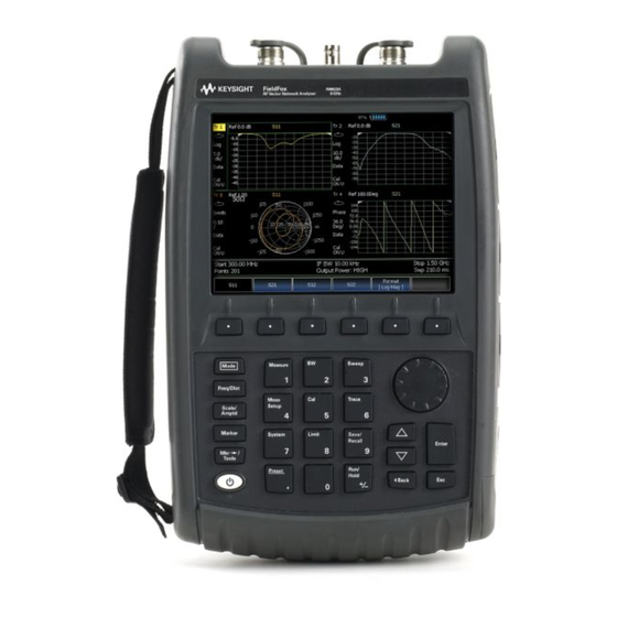
- Page 1 User's Guide Keysight Technologies FieldFox RF Network Analyzers N9923A...
-
Page 2: Safety Notices
DOCUMENT THAT CONFLICT WITH writing elsewhere in the EULA. THESE TERMS, THE WARRANTY Keysight shall be under no obligation © Keysight Technologies, Inc. TERMS IN THE SEPARATE to update, revise or otherwise modify 2014-2016 the Software. - Page 3 URLs, according to the name of your product: http://www.keysight.com/find/fieldfox To receive the latest updates by email, subscribe to Keysight Email Updates at the following URL: http://www.keysight.com/find/MyKeysight Information on preventing instrument damage can be found at: www.keysight.com/find/PreventingInstrumentRepair...
- Page 4 If you do not have access to the Internet, please contact your Keysight field engineer. In any correspondence or telephone conversation, refer to the Keysight product by its model number and full serial number. With this information, the Keysight representative can determine whether your product...
-
Page 5: Table Of Contents
Format ..............46 Keysight N9923-90001 User’s Guide... - Page 6 CAT Mode Settings ............77 Keysight N9923-90001 User’s Guide...
- Page 7 QuickCal (Option 112) ........... 106 Keysight N9923-90001 User’s Guide...
- Page 8 Measurement Selection...........139 Keysight N9923-90001 User’s Guide...
- Page 9 Zeroing ............. . . 167 Keysight N9923-90001 User’s Guide...
- Page 10 Printing..............205 Keysight N9923-90001 User’s Guide...
- Page 11 How to configure LAN settings ..........231 Keysight N9923-90001 User’s Guide...
- Page 12 Packaging Markings ............258 Keysight N9923-90001 User’s Guide...
- Page 13 ............... . 268 Keysight N9923-90001 User’s Guide...
- Page 14 Contents Keysight N9923-90001 User’s Guide...
-
Page 15: Overview
Keysight N9923A Handheld Analyzer User’s Guide Overview Options and Features The FieldFox may be ordered to include the following options and features: Options and Features Learn More: Chapter 3, “NA RF Vector NA Mode (Network Analyzer) Mode”, on page 37... - Page 16 Built-in cal kit. Industry first! Power Meter Mode (Option 302) Chapter 8, “Power Meter (USB) Mode”, on page 125 Use with Keysight External USB Power Sensors Chapter 11, “VVM Vector Voltmeter (VVM) Mode (Option 308) (Vector Voltmeter) Mode - Option 308”,...
-
Page 17: Accessories
“Language” on page 215 FieldFox Options: For a comprehensive list, view the FieldFox Configuration http://literature.cdn.keysight.com/litweb/pdf/5990-9836EN.pdf Guide at: Accessories The following accessories are included with every N9923A FieldFox. Spare accessories can be ordered at any time. Table 1-1 Accessories Accessory Part Description... -
Page 18: Fieldfox Manuals, Software, And Supplemental Help
The six Softkey menus change dynamically and follow these color conventions: — Softkey Blue indicates an available setting. Softkey — Green indicates a change in menu level when selected. — Softkey Black indicates the default or selected setting. Keysight N9923-90001 User’s Guide... -
Page 19: Safety Notes
Denotes a hazard. It calls attention to a procedure which, if not correctly performed or adhered to, could result in injury or loss of life. Do not proceed beyond a warning note until the indicated conditions are fully understood and met. Keysight N9923-90001 User’s Guide... - Page 20 Overview FieldFox Manuals, Software, and Supplemental Help Keysight N9923-90001 User’s Guide...
-
Page 21: Preparing For Initial Use Of Your New Fieldfox
FieldFox. Various AC power cables are available from Keysight that are unique to specific geographic areas. You can order additional AC power cables that are correct for use in different areas. For the power cord part number information please http://www.keysight.com/find/fieldfox... -
Page 22: Install The Lithium-Ion Battery
Learn more about the lithium-ion battery in Lithium-Ion Battery”, on page 239. Battery charge status is viewable: — In the upper-right corner of the screen. — On the Battery screen. To access the screen, select System, Service Diagnostics, and Battery. Keysight N9923-90001 User’s Guide... -
Page 23: Fieldfox On/Off Settings
— To turn power ON, briefly press the power button. Boot-up takes about 1 minute. — To switch to Stand by mode (low battery drain), briefly press the power button. See the Note above concerning Stand By. Keysight N9923-90001 User’s Guide... -
Page 24: Power Button Led Status
FieldFox. Do NOT store the FieldFox in the soft-case while powered ON or in Standby mode. How to monitor the internal FieldFox temperature: — Press System, then Service Diagnostics. Internal Temperatures. — Then Keysight N9923-90001 User’s Guide... -
Page 25: Temperature Control Mode
Maximum Input Voltages and Power: RF IN/OUT Connectors: ±50 VDC, +23 dBm RF — DC Input: -19 to 19 VDC, 40 Watts maximum when charging battery — Learn more about Maximum power and voltages in the FieldFox Data Sheet. Keysight N9923-90001 User’s Guide... - Page 26 FieldFox, may damage the instrument input circuitry. To avoid such damage, it is recommended to dissipate any static charges by temporarily attaching a short to the cable or antenna prior to attaching to the FieldFox. Keysight N9923-90001 User’s Guide...
-
Page 27: Take The Fieldfox Tour
Preparing for Initial Use of Your New FieldFox Take the FieldFox Tour Take the FieldFox Tour Front Panel Keysight N9923-90001 User’s Guide... - Page 28 Displays a sub-menu for marker functions “All about Markers” page 174 Exits and closes the dialog box or clears the character input Save/Recall Saves the current trace or recalls saved data from memory “Saving Recalling Files” on page 192 Keysight N9923-90001 User’s Guide...
- Page 29 Alternative color modes exist that maximize viewing in direct sunlight conditions, as well as other conditions such as nighttime work. Clean the Transflective screen with gentle and minimal wiping using Isopropyl alcohol applied to a lint-free cloth. Keysight N9923-90001 User’s Guide...
-
Page 30: Top Panel
Ext Ref Reference. Source” on page 226. Maximum: 5.5 VDC. External Triggering is not used on the N9923A. Port 2 For CAT and NA mode. Contains source and B/R2 receivers. “CAT Mode Settings” on page 77 Maximum: ±50 VDC, +23 dBm RF. - Page 31 Standard USB connector used to connect a power sensor for Power Meter “How to Connect the Mode. Also used to save files to a USB flash drive. Power Sensor” on page 127 Use of Keyboard and Mouse is NOT supported. Audio output jack. Keysight N9923-90001 User’s Guide...
-
Page 32: Screen Tour
Data / Mem Display (CAT and NA) “All about Trace Math” on page 189 Mode dependent Resolution Setting Measurement Start Freq or Distance Mode dependent Bandpass / Lowpass setting (Fault Meas) “DTF Measurement IF BW in NA Mode Settings” on page 91 Keysight N9923-90001 User’s Guide... - Page 33 “Date and Time” on page 218 Marker Readout “All about Markers” on page 174 Battery Status “Viewing the Battery Charge Status” on page 239 Measurement Type (CAT and NA) Reference Level Mode dependent Reference Position Mode dependent Keysight N9923-90001 User’s Guide...
-
Page 34: How To Enter Numeric Values
Select Frequency multipliers as follows: — Gigahertz (1e9 Hertz) — Megahertz (1e6 Hertz) — Kilohertz (1e3 Hertz) — Hertz Select Time multipliers as follows: — Seconds — milliseconds (1e–3) — microseconds (1e–6) — nanoseconds (1e–9) — picoseconds (1e-12) Keysight N9923-90001 User’s Guide... -
Page 35: Connector Care
In addition, a dirty or damaged connector can destroy connectors that are mated to it. For this reason, NEVER use a damaged connector. See also http://na.support.keysight.com/pna/connectorcare/Connector_Care.htm Keysight N9923-90001 User’s Guide... - Page 36 Preparing for Initial Use of Your New FieldFox Connector Care Keysight N9923-90001 User’s Guide...
-
Page 37: Na (Network Analyzer) Mode
Keysight N9923A Handheld Analyzer User’s Guide NA (Network Analyzer) Mode Learn more about NA Mode measurements in the FieldFox Supplemental Online Help: http://na.support.keysight.com/fieldfox/help/SupHelp/FieldFox.htm. In this Chapter “About S-parameters” on page 39 “Mixed-Mode S-Parameters” on page 40 “Parameter Conversion” on page 41 “Receiver Measurements”... - Page 38 “Why and When to Calibrate” on page 103 “All about Markers” on page 174 “All about Limit Lines” on page 185 “All about Trace Math” on page 189 Learn how to make 75Ω (ohm) Measurements in the Supplemental Online Help: http://na.support.keysight.com/fieldfox/help/SupHel p/FieldFox.htm Keysight N9923-90001 User’s Guide...
-
Page 39: Na Mode Settings
When the source comes from port 2, the measurement is said to be in the reverse direction S11 and S22 reflection measurements are used to measure the amount of reflections off the corresponding DUT port. Low reflections means there is a good impedance match between the source and DUT. Keysight N9923-90001 User’s Guide... -
Page 40: Mixed-Mode S-Parameters
Because the FieldFox has only two test ports, only reflection measurements are available. Connect the balanced input or output of your DUT to the FieldFox ports 1 and 2 For highest accuracy, a Full 2-port calibration is required. Keysight N9923-90001 User’s Guide... -
Page 41: Parameter Conversion
S21 and S12. When the S-parameter is changed, the appropriate conversion changes automatically. ——Refl The displayed S-parameter is converted to Z or Y reflection, regardless of whether the S-parameter is reflection (S11 or S22) or transmission (S21 or S12). Keysight N9923-90001 User’s Guide... -
Page 42: Receiver Measurements
The FieldFox sets the source port based on the selected receiver. —Port 1 Select when measuring transmission at B receiver. —Port 2 Select when measuring reverse transmission at A receiver. Learn more about Raw Receiver Measurements at the FieldFox Supplemental Online Help: http://na.support.keysight.com/fieldfox/help/SupHelp/FieldFox.htm Keysight N9923-90001 User’s Guide... -
Page 43: Multi-Trace Configurations
ACTIVE trace in the same manner as when a single trace is present. — By default, a marker is created on ALL traces. However, they can be created “Coupled individually by disabling Coupled Markers. Learn more in Markers” on page 176. Keysight N9923-90001 User’s Guide... - Page 44 4, Only traces that are shown can be activated. How to maximize the viewing of the active trace — Press System 7 Full Screen. — Then — Press any key to return to the standard display. Keysight N9923-90001 User’s Guide...
-
Page 45: Quick Settings
Edit. —When finished changing a value, press Dock Window — Press to relocate the Settings table to a position relative to the trace window. The Dock Window setting persists through a Preset. Choose from the following: Keysight N9923-90001 User’s Guide... -
Page 46: Calibration Settings
Displays positive values only. Y-axis: Unitless (U) for ratioed measurements; Watts (W) for unratioed measurements. —VSWR Used mainly for S11 and S22. Displays unitless reflection data. —Phase Displays phase in degrees. The trace ‘wraps’ every 360 degrees, from +180 to –180, for easy scaling. Keysight N9923-90001 User’s Guide... -
Page 47: Frequency Range
— Then choose from the following: Start Stop — frequencies – Specify the beginning and end of the sweep. Center Span — frequencies - Specify the center frequency and span of frequencies (half on either side of center). Keysight N9923-90001 User’s Guide... -
Page 48: Scale Settings
Values must be between 0 (TOP line) and 10 (BOTTOM line) Scale annotation on the FieldFox screen —Reference Line = red arrow —Ref Level = –40 dB —Ref Position = 1 —Scale = 2 dB per d ivision Keysight N9923-90001 User’s Guide... -
Page 49: Magnitude Offset
Port Extensions. Learn “Port Extensions” on page how in “Phase Offset” on page Learn how to set Phase formats in How to set Electrical Delay — Press Scale / Amptd More — Then Electrical Delay — Then Keysight N9923-90001 User’s Guide... -
Page 50: Phase Offset
In addition, noise is further reduced by continuing to average after calibration. How to set Averaging — Press BW 2. Keysight N9923-90001 User’s Guide... -
Page 51: If Bandwidth
The number of adjacent data points that are averaged is known as the smoothing aperture. Aperture is set by specifying a percentage of the X-axis span. Trace smoothing does NOT significantly increase measurement time. Keysight N9923-90001 User’s Guide... -
Page 52: Single Or Continuous Measure
When the Resolution is changed after a calibration is performed, the cal “Interpolation *” on page 119. becomes interpolated. Learn more in How to set Resolution — Press Sweep 3. — Then Resolution. Keysight N9923-90001 User’s Guide... -
Page 53: Sweep Time
Power Level settings in this mode will NOT change Power Level settings in other modes. To help prevent damage to your DUT, use caution when changing modes with your DUT connected to the FieldFox test ports. Keysight N9923-90001 User’s Guide... -
Page 54: System Impedance (Z0)
— Then type either 50 or 75 and press Enter Port Extensions Port extensions allow you to electrically move the calibration reference plane on either port 1 or port 2 after you have performed a calibration. Keysight N9923-90001 User’s Guide... - Page 55 — Then enter time value using the numeric keypad, the arrows, or the Enter rotary knob. Press or select a seconds (time) multiplier. You can also set Port Extensions by pressing Meas Setup 4 then Calibration (settings). Keysight N9923-90001 User’s Guide...
-
Page 56: Velocity Factor
If you have already set up your display and do not want to lose it, then save the current state to a state file. Learn how in “State Files” on page 195. The following procedure will overwrite your display state. — Press Mkr ->/ Tools Keysight N9923-90001 User’s Guide... - Page 57 —State – Choose from Normal, Delta, or OFF. The default marker (1) is created in Normal. Learn more in “Marker Functions” on page 183. —Enabled – Turns the Big Readout of the corresponding marker ON and OFF. The default marker (1) is set ON by default. Keysight N9923-90001 User’s Guide...
-
Page 58: Increase Dynamic Range
The following procedure MAY increase the dynamic range of your NA mode measurement. The results you see will depend on the performance of your DUT. With an S21 trace active: 1. With RF OUT (port-2) open, press Trace 6 then Math and Memory then Data->Mem Keysight N9923-90001 User’s Guide... - Page 59 NA (Network Analyzer) Mode NA Mode Settings 2. Re-connect the DUT. 3. Press Data Math then Data-Mem Keysight N9923-90001 User’s Guide...
- Page 60 NA (Network Analyzer) Mode NA Mode Settings Keysight N9923-90001 User’s Guide...
- Page 61 Keysight N9923A Handheld Analyzer User’s Guide 4 Time Domain – Option 010 With NA Mode, Time Domain Reflectometry (Opt 010), frequency information is used to calculate and display measurements with time as the horizontal display axis. The response values appear separated in time allowing a different perspective of the test device's performance and limitations.
-
Page 62: Time Domain - Option 010
Time Domain – Option 010 Gating Settings “Start, Stop, Center, and Span Gate Times” on page 73 “Gating Type” on page 73 Keysight N9923-90001 User’s Guide... -
Page 63: Overview
Markers that are created on a Time Domain trace can be used to pinpoint the distance of the mismatch from the reference plane. For more information on Time Domain theory, see http://literature.cdn.keysight.com/litweb/pdf/5989-5723EN.pdf Keysight N9923-90001 User’s Guide... -
Page 64: Time Domain (Transform) Settings
Time Domain measurements are calculated. Increasing the data points will improve measurement resolution. However, more data points will usually result in slower sweep updates. Set frequency range and points before selecting Stimulus Mode. Keysight N9923-90001 User’s Guide... -
Page 65: Stimulus (Mode)
How to set Start and Stop time — Press Measure Setup 4 Transform — Then Transform Start Stop — Then Keysight N9923-90001 User’s Guide... -
Page 66: Distance Units
Time Domain response. The Window setting reduces the abruptness of the frequency domain transitions. This causes you to make a trade off in the Time Domain response. Keysight N9923-90001 User’s Guide... -
Page 67: Window Settings
Percent Kaiser Beta 6.50 13.00 Impulse Width 100.455 ps 168.501 231.284 Window Settings Window settings provide the ability to choose between optimizing TDR measurements for resolving closely-spaced faults or for the ability to measure low-level faults. Keysight N9923-90001 User’s Guide... - Page 68 (Default setting) Med ium — – Compromise between Min and Max window settings. — Minimum – Best Response Resolution, providing the ability to resolve between two closely-spaced responses. Done Ed — Then press — Again press Done. Keysight N9923-90001 User’s Guide...
-
Page 69: Line Loss And Velocity Factor
— Line Loss is specified in dB/m (or ft). In addition to the length of the cable, loss is also directly proportional to the frequency of the signal that passes through the cable. The following is an example showing how Line Loss works: Keysight N9923-90001 User’s Guide... -
Page 70: Data Chain
— Standard – The normal FieldFox data processing chain. Transform calculations are performed AFTER error correction and trace math. — 8510 – The data processing chain used by the Keysight 8510 network analyzer. Transform calculations are performed BEFORE error correction and trace math. -
Page 71: Trace Settings
Gate Enable Enable Gating for the specific trace. — Select the trace. — Press Measure Setup 4 Transform — Then — Then choose from: —On Trace displays Time Domain data. —Off Trace displays frequency domain data. Keysight N9923-90001 User’s Guide... -
Page 72: Gating
The following image shows how gating can affect measurement results. All 4 traces show the same S11 measurement. Trace 1 shows the frequency response without gating enabled. Trace 2 shows the transform response without gating enabled. Trace 3 shows the transform response with gating enabled. Keysight N9923-90001 User’s Guide... -
Page 73: How To Make Time Domain Gating Settings
The gate start and stop flags on the display point toward the part of the trace you want to keep. Choose from the following: Bandpass — KEEPS the responses within the Gating Start and Stop times. Notch — REMOVES the responses within the Gating Start and Stop times. Keysight N9923-90001 User’s Guide... - Page 74 If you specify a gate span that is smaller than the minimum span, the response will show the following effects: — distorted gate shape that has no passband — distorted shape — incorrect indications of start and stop times — may have increased sidelobe levels. Keysight N9923-90001 User’s Guide...
-
Page 75: Cat (Cable And Antenna Test) Mode
Keysight N9923A Handheld Analyzer User’s Guide CAT (Cable and Antenna Test) Mode CAT Mode is typically used to test an entire transmission system, from the transmitter to the antenna. This process is sometimes referred to as Line Sweeping. CAT Mode is similar to NA (Network Analyzer) Mode. Learn more in the Supplemental Online Help: http://na.support.keysight.com/fieldfox/help/SupH... - Page 76 Chapter 7, “Calibration for NA, CAT, and VVM Modes”, on page 101 “All about Markers” on page 174 “All about Limit Lines” on page 185 “All about Trace Math” on page 189 Making 75Ω (ohm) Measurements at the FieldFox Supplemental Online Help: http://na.support.keysight.com/fieldfox/help/SupHelp/FieldFox.htm Keysight N9923-90001 User’s Guide...
-
Page 77: Cat Mode Settings
The higher the trace is on the screen, the more energy being reflected back to the FieldFox. DTF (VSWR) — Distance to Fault in VSWR format. Keysight N9923-90001 User’s Guide... -
Page 78: Quick Settings Table
Settings table to a position relative to the trace window. The Dock Window setting persists through a Preset. Choose from the following —Full (Default setting) Only the Settings table is shown on the screen. The trace window is temporarily not shown Keysight N9923-90001 User’s Guide... -
Page 79: Frequency Range
Autoscales all of the traces on the screen, useful only for dual-trace configurations. 2. Set Scale, Reference Level, and Reference Position: — Scale Manually enter a scale per d ivision to view specific areas of the trace Keysight N9923-90001 User’s Guide... -
Page 80: Averaging
To achieve the highest dynamic range, select NA mode and reduce the IF Bandwid th setting. Learn more about dynamic range in “Increase Dynamic Range” on page 58 How to set Trace Averaging — Press BW 2. Keysight N9923-90001 User’s Guide... -
Page 81: Smoothing
--> while the sweep occurs —Continuous ON OFF Makes continuous sweeps. This is the typical setting when battery power is not critical. You can also use Run / Hold +/- to toggle between Single and Continuous. Keysight N9923-90001 User’s Guide... -
Page 82: Resolution (Number Of Data Points)
Chapter 1, “Overview.” How to set Sweep Time — Press Sweep 3. Min Swp Time. — Then — Enter a value using the numeric keypad. “Multiplier Abbreviations” on page — Press a multiplier key. Learn more in Keysight N9923-90001 User’s Guide... -
Page 83: Output Power
To achieve a flattened output power, reduce the power level or stop frequency. —Then press Nominal Power —Then enter a value using the numeric keypad, the arrows, or the rotary knob. Keysight N9923-90001 User’s Guide... -
Page 84: Coupled Frequency
Start or Stop frequency is selected, Coupled Frequency is automatically set to OFF. —The DTF measurement is made using the frequencies as determined by the DTF Frequency Mode setting. Learn more in “DTF Measurement Settings” on page Keysight N9923-90001 User’s Guide... -
Page 85: Interference Rejection
— Then choose from the following: —Off No interference rejection and fastest possible sweep speed —Minimum The lowest level of Interference rejection. —Med ium The medium level of Interference rejection. —Maximum The highest level of Interference rejection. Keysight N9923-90001 User’s Guide... -
Page 86: Return Loss Measurements
A deteriorated cable is not usually apparent in a Distance to Fault measurement, where more obvious and dramatic problems are identified. A Cable Loss measurement is necessary to measure the accumulated losses throughout the length of the cable. Keysight N9923-90001 User’s Guide... -
Page 87: How To Make A 1-Port Cable Loss Measurement
12.Remove the LOAD and leave the end of the cable to be tested open. 13.Press Data Math then Data – Mem. The ripple in the measurement is removed. These minor imperfections in the cable should not be considered in the Cable Loss measurement. Keysight N9923-90001 User’s Guide... -
Page 88: 2-Port Insertion Loss Measurements
— Connect the DUT and view the insertion loss measurement results. When measuring very long lengths of cable, it may be necessary to increase “Sweep Time” on page 82. Learn why in the the sweep time. Learn how in Supplemental Online Help: http://na.support.keysight.com/fieldfox/help/SupHelp/FieldFox.htm Keysight N9923-90001 User’s Guide... -
Page 89: Dtf (Distance To Fault) Measurements
Keysight N9923A Handheld Analyzer User’s Guide DTF (Distance to Fault) Measurements CAT Mode Distance to Fault (DTF) measurements are generally used to locate problems, or faults, in a length of cable or transmission line. In this chapter, the cable to be tested is referred to as the DUT (Device Under Test). -
Page 90: How To Make Dtf Measurements
10. Connect the start end of the DUT to the FieldFox. 11. Press Meas Setup 4 then Settings then Next Page. If the Alias-free Range setting is False, then you may see Alias faults on the screen. Learn more page Keysight N9923-90001 User’s Guide... -
Page 91: Dtf Measurement Settings
Faults are displayed on the Y-axis in return loss format, expressed as a positive number in dB. —DTF (VSWR) Faults are displayed on the Y-axis in SWR. Learn more about SWR at the FieldFox Supplemental Online Help: http://na.support.keysight.com/fieldfox/help/SupHelp/FieldFox.ht Keysight N9923-90001 User’s Guide... -
Page 92: Dtf Start And Stop Distance
Frequency Mode — Choose one of the following: —Lowpass Mode The frequency range of a DTF measurement is set automatically based on the Start and Stop Distances. Use Lowpass mode when the DUT is a cable ONLY. Keysight N9923-90001 User’s Guide... -
Page 93: Coupled Frequency
Coupled Frequency When both a DTF and non-DTF measurements are present, this setting allows you to have different frequency ranges for each measurement. Learn more in “Coupled Frequency” on page Keysight N9923-90001 User’s Guide... -
Page 94: Cable (Correction) Specifications
Cable Loss and Velocity factor can be entered using one of the following methods: — Manually enter cable loss and velocity factor for the measurement. — Select or create a cable file which contains the cable loss and velocity factor. With a DTF measurement present: Keysight N9923-90001 User’s Guide... - Page 95 “How the Freq/Loss pairs are applied” below. — Optionally choose from the following: —Previous / Next Page Quickly scrolls through pages of Freq/Loss data. —Add Data Add a blank Freq/Loss pair to the table, —Delete/Clear then: Keysight N9923-90001 User’s Guide...
- Page 96 When the cable file contains two or more Freq/Loss pairs, the Loss value that is used is interpolated from the Freq/Loss pairs and the DTF center frequency. For example, using a cable file with the following Freq/Loss pairs: 1 GHz: 0.1 dB/m 2 GHz: 0.2 dB/m Keysight N9923-90001 User’s Guide...
-
Page 97: Window Settings
(Default setting) —Med ium – Compromise between Min and Max window settings. —Minimum – Best Response Resolution, providing the ability to resolve between two closely-spaced responses. Done Ed — Then press — Again press Done. Keysight N9923-90001 User’s Guide... -
Page 98: Dtf Units
An alias fault is not a true device response. An alias fault appears because of the method used to convert frequency to time. On the DTF Settings page (above) the c - Alias-free Range = Off setting indicates alias images MAY appear on the screen. Keysight N9923-90001 User’s Guide... - Page 99 FieldFox. Re-reflections are measured at the FieldFox as mirror images of the original faults. The largest fault is the open end of the cable. To avoid confusion, set the Stop distance shortly after that fault. Keysight N9923-90001 User’s Guide...
- Page 100 DTF (Distance to Fault) Measurements DTF Measurement Settings Keysight N9923-90001 User’s Guide...
-
Page 101: Chapter 7, "Calibration For Na, Cat, And Vvm Modes
Keysight N9923A Handheld Analyzer User’s Guide Calibration for NA, CAT, and VVM Modes Calibration removes the systematic errors that are associated with measurements in NA, CAT, and VVM Modes. Key presses are identical in all of these Modes. In this Chapter “Why and When to Calibrate”... - Page 102 Calibration for NA, CAT, and VVM Modes See Also Learn How to Make 75 ohm Measurements at the FieldFox Supplemental Online Help: http://na.support.keysight.com/fieldfox/help/SupHelp/FieldFox.htm Keysight N9923-90001 User’s Guide...
-
Page 103: Calibration For Na, Cat, And Vvm Modes
OPEN. —A LOAD standard absorbs almost ALL of the incident signal and very little signal is reflected back to the source. Keysight N9923-90001 User’s Guide... -
Page 104: Calready
Learn how to see when your factory CalReady calibration was performed in “System Information” on page 235. How to Perform a Calibration Press Esc at any time to end the calibration process. In CAT, NA, or VVM Mode, press Cal 5. Keysight N9923-90001 User’s Guide... - Page 105 — View Cal – Shows the properties of the current calibration. Learn more in “View Cal” on page 114. — More – Learn about Cal Ready Properties in “CalReady” on page 104. Press Esc at any time to end the calibration process. Keysight N9923-90001 User’s Guide...
-
Page 106: Quickcal (Option 112)
DUT. Although there is no Cal Kit required, selecting the connector type (limited to Type-N and 7/16) and gender from the list provides an accurate OPEN model which means a more accurate calibration. If the DUT connector type is not listed, select Unknown/Other. Keysight N9923-90001 User’s Guide... - Page 107 Measure press under the following conditions: —When a jumper cable has too much loss. If a ‘Cal Failed’ error appears and you skipped the Load measurement, then perform the Cal again but include measuring the Load. Keysight N9923-90001 User’s Guide...
-
Page 108: Mechanical Cal
Mechanical Calibration is performed using discrete standards from a Cal Kit. Several Cal Kit definitions are built into the FieldFox. To learn about Cal Kit definitions, refer to the Application Note, “Specifying Calibration Standards and Kits for Keysight Vector Network Analyzers,” available online at http://literature.cdn.keysight.com/litweb/pdf/5989-4840EN.pdf Visit www.keysight.com/find/fieldfoxsupport... - Page 109 If the DUT connector type, gender, or Cal Kit is NOT correct for the DUT ports to be calibrated, then: —Press Change DUT Connectors to select the correct connector types that are on your DUT. —For each port: —Use the arrows or rotary knob to change the DUT connector type. Keysight N9923-90001 User’s Guide...
-
Page 110: Ecal
Cal Kit covers the frequency range of the measurement. You can verify the frequency range of your Cal Kit at: www.keysight.com/find/fieldfoxsupport. Click Cal Kits. — Follow the Cal Wizard prompts. Connect the specified standard at the point where the DUT will be connected, then press Measure. - Page 111 Mechanical Cal Setup page of the CalWizard. However, a User Characterization can NOT be PERFORMED using the FieldFox. It must be performed using a bench top Keysight VNA, such as the PNA or ENA. Learn more about User Characterization at the PNA Help website: http://na.tm.keysight.com/pna/help/latest/S3_Cals/ECal_User_Characteriza...
-
Page 112: Simple Response Cals
CalReady are updated by the measured Short or Open that is used during the calibration. 1-port response cals are also available from the Mechanical Cal menu. Learn more in “Calibration Type” on page 114. Keysight N9923-90001 User’s Guide... - Page 113 User Cal (Ex: Response Cal) is correcting ONLY the appropriate measurement. For example, when an Open Response Cal on Port 2 is performed, CAL ON U is shown for an S22 measurement only. Keysight N9923-90001 User’s Guide...
-
Page 114: View Cal
S-parameters. However, there may be times when you may want a little more accuracy or a little faster sweep time. The following information can help you learn about the various calibration choices. Keysight N9923-90001 User’s Guide... - Page 115 Most comprehensive calibration. Corrects all S-parameters DUT: Non-Insertable or Insertable Standards: OPEN, SHORT, LOAD on BOTH ports. Any THRU between ports. For more information on the Unknown THRU process, see the FieldFox Supplemental Online Help: http://na.support.keysight.com/fieldfox/help/SupHelp/FieldFox.htm Keysight N9923-90001 User’s Guide...
- Page 116 114) but NOT as good as full 1-port cal. Corrects either S11 or S22. “Simple Can be used with Isolation (see following section). Learn more in Response Cals ” on page 112 DUT: Non-Insertable or Insertable S-parameters Corrected: S11 or S22 Keysight N9923-90001 User’s Guide...
-
Page 117: Isolation Step Of A 2-Port Cal
Therefore, it is VERY IMPORTANT to set the frequency range of the measurement WITHIN the frequency range of the waveguide Cal Kit. Otherwise, an error message will appear during the ‘Calculating Steps’ portion of the calibration. Keysight N9923-90001 User’s Guide... - Page 118 Calibration for NA, CAT, and VVM Modes Waveguide Cal Kits Keysight sells two waveguide Cal Kit series: the premium 11644A series and www.Keysight.com the economy N9911X series. Both are available online at Effective Velocity Factor Velocity factor is the speed at which an electromagnetic signal passes through the transmission medium relative to the speed of light.
-
Page 119: Enhanced Response Optimization
FieldFox was calibrated. If these settings change after performing a calibration, the FieldFox will interpolate the calibration so that VERY accurate measurements continue to be made. Keysight N9923-90001 User’s Guide... -
Page 120: Cal On ? - Questionable Accuracy
“CalReady” on page 104. connected to the test ports. Learn more in This setting does NOT survive Preset or Power ON/OFF. More — Press Cal 5 then CalReady — Then press to toggle between the following selections: Keysight N9923-90001 User’s Guide... - Page 121 Memory. — Press — Press Cal 5 then More — Select a CalReady Cal to compare with the current setting. — Press Esc to exit the cal menu. — View the differences in the two traces. Keysight N9923-90001 User’s Guide...
-
Page 122: Verifying Calibration And Jumper Cable Integrity
— If the measurement trace is relatively stable, the jumper cable is of good quality. — If you observe significant movement in the peaks of the measurement trace when moving the cable (>5 dB), the jumper cable may need to be replaced. Keysight N9923-90001 User’s Guide... -
Page 123: Calibration Method Summary
—When the temperature changes more than about 10°F (5°C) —When the connection to the DUT requires a different jumper cable or adapters. —When any of the following measurement settings change: Frequency Range, Power Level, IF BW, and Resolution. Keysight N9923-90001 User’s Guide... - Page 124 Calibration for NA, CAT, and VVM Modes Calibration Method Summary Keysight N9923-90001 User’s Guide...
- Page 125 Keysight N9923A Handheld Analyzer User’s Guide Power Meter (USB) Mode Power Meter measurements, available with Option 302, are made with Keysight USB power sensors. Power readings are displayed on the FieldFox screen. In this Chapter “Supported Power Sensors” on page 127 “How to Connect the Power Sensor”...
-
Page 126: Power Meter (Usb) Mode
Power Meter (USB) Mode “Step Detection Mode” on page 133 “Limits” on page 133 See Also “FOPS Settings” on page 139 Keysight N9923-90001 User’s Guide... -
Page 127: Supported Power Sensors
Power Meter (USB) Mode Supported Power Sensors For a complete list of supported Keysight USB Power Sensors, please visit: www.keysight.com/find/usbsensorsforfieldfox The FieldFox does NOT support the following Keysight USB Power Sensor features: External Triggering (Time Gated Burst Power Measurement), Power Sweep Operation, and Frequency Sweep Operation. External Zeroing is NOT allowed on the U2020 X-series Power Sensors. -
Page 128: Usb Power Meter Settings
Zeroing The Keysight USB Power Sensors perform Internal Zeroing automatically. Because Keysight USB Power Sensors have an internal switch, Internal Zeroing does NOT require that the power source be turned OFF. For highest measurement accuracy, when measuring power levels below –30 dBm, External Zeroing should be performed. -
Page 129: Frequency
NO warning is shown. Frequency A table of correction factors versus frequency is stored within Keysight Power Sensors. The frequency of the power to be measured is entered in the FieldFox so that the appropriate correction factor can be used. - Page 130 Type a number and select the units or press Enter. This value is limited to 100 dBm. Autoscale: Using Autoscale, the current reading is used for the center of the scale, and Min and Max values are set accordingly. Keysight N9923-90001 User’s Guide...
-
Page 131: Relative And Offset Power Measurements
— Press Meas Setup 4 or Scale / Amptd, More — Then Unit. — Then choose from the following: dBm (dB) — Sets Power Meter display to dBm or dB. Watt (%) — Sets Power Meter display to Watts or %. Keysight N9923-90001 User’s Guide... -
Page 132: Resolution
This setting can be changed at any time without affecting calibration accuracy. How to set Single or Continuous — Press Sweep 3. — Then choose one of the following: Keysight N9923-90001 User’s Guide... -
Page 133: Step Detection Mode
You can also use Run / Hold +/- to toggle between Single and Continuous. Step Detection Mode The FieldFox supports the Step Detection feature that is present in Keysight USB power sensors. When enabled, this feature reduces settling time after a significant step in the measured power. - Page 134 Power Meter (USB) Mode USB Power Meter Settings Keysight N9923-90001 User’s Guide...
- Page 135 FOPS is accessed through (and requires) Option 302 USB Power Meter Mode. With both options installed, you can send a signal with the FieldFox internal source at one frequency, and measure this signal with a Keysight U-Series USB Power Sensor at another frequency.
- Page 136 Frequency Offset Using Power Sensor (FOPS) – Option 208 “Amplitude Markers” on page 143 “Trace Math” on page 143 See Also “All about Trace Math” on page 189 Keysight N9923-90001 User’s Guide...
-
Page 137: Frequency Offset Using Power Sensor (Fops) - Option 208 Overview
— The USB power sensor, with an equally long USB/LAN cable, is connected to the IF Output. USB/LAN extenders are NOT provided with the FieldFox or Keysight USB power sensors. — Conversion gain/loss is measured at power sensor. Keysight N9923-90001 User’s Guide... - Page 138 Frequency Offset Using Power Sensor (FOPS) – Option 208 Overview The dynamic range with FOPS may be significantly different when using various power sensors. In general, the lower frequency range sensors have better dynamic range. Keysight N9923-90001 User’s Guide...
-
Page 139: Fops Settings
— Press Mode Power Meter (USB Sensor) — Then — Then connect a USB Power Sensor to either FieldFox USB port. — For a complete list of supported Keysight USB Power Sensors, please visit: www.keysight.com/find/usbsensorsforfieldfox Measurement Selection — Press Measure 1 —... -
Page 140: Sweep Type And Frequency
Sweep Type and Frequency Set the source and receiver frequencies for the FOPS measurements. The receiver is a Keysight U-Series Power Sensor. These are broadband measurement devices, which means that they measure power over a very wide frequency range. Tables of frequency and power correction factors are stored within the power sensors. - Page 141 Src = 2 GHz to 3 GHz Offset = 3.8 GHz Rx = 1.800 GHz to 800 MHz Positive Offset, RxSwp = (Offs + Src) Src = 2 GHz to 3 GHz Offset = 3.8 GHz Keysight N9923-90001 User’s Guide...
-
Page 142: Power Sensor Settling
Freq Step Size — Both settings control the number of power sensor measurements between the Start and Stop frequencies. Enter one setting and the other will be changed automatically. There must be at least two data points. Keysight N9923-90001 User’s Guide... -
Page 143: Amplitude Markers
When Trace, then Data -> Mem is pressed, if a Src Power trace is active, then RxPower is actually stored into memory. To Compare Src Power (Input) and Rx Power (Output): 1. Meas Rx Power 2. Store to memory 3. View Data & Memory 4. Meas Src Power. Keysight N9923-90001 User’s Guide... - Page 144 Frequency Offset Using Power Sensor (FOPS) – Option 208 FOPS Settings Keysight N9923-90001 User’s Guide...
-
Page 145: Pulse Measurements Mode - Option
10 Pulse Measurements Mode – Option 330 Pulsed power meter measurements, available with Option 330, are made with Keysight U2020 X-Series USB Peak Power Sensors. These sensors are capable of detecting, measuring, and storing data from a train of pulses at the RF input. - Page 146 Many of the features included with the FieldFox Pulse Measurements Mode are discussed in detail in these two documents: — Keysight U2020 X-Series USB Peak Power Sensors Programmer’s Guide. http://literature.cdn.keysight.com/litweb/pdf/U2021-90003.pdf — “Best Practices For Making The Most Accurate Radar Pulse Measurements”...
-
Page 147: Supported Power Sensors
Pulse Measurements Mode – Option 330 Supported Power Sensors Supported Power Sensors Pulse measurements are made using any of the Keysight U2020 X-Series USB Peak Power Sensors. Zeroing of the U2020 X-Series USB Peak Power Sensors is performed automatically at power up, every 5 seconds, and prior to measuring low level signals. -
Page 148: Pulse Measurement Settings
— Learn how to set Display Units in“Display Units” on page 131. — Learn how to set Limits in “All about Limit Lines” on page 185. Frequency / Time How to set Frequency — Press Freq/Dist — Then choose from the following: Keysight N9923-90001 User’s Guide... -
Page 149: Zoom Window
Closes the zoom window. Zoom Center While monitoring the T within the blue vertical posts on Tr 1, — enter a value for the center time using the numeric keypad, the arrows, or the rotary knob. Keysight N9923-90001 User’s Guide... -
Page 150: Scale
Offset values are limited to +/- 100 dB. Averaging Averaging helps to reduce the effects of random noise on a measurement. The more measurements that are averaged, the greater the amount of noise reduction. Averaging is allowed for all pulse measurements. Keysight N9923-90001 User’s Guide... -
Page 151: Video Bandwidth
This setting determines whether the FieldFox continuously queries the USB Single Power Sensor for data, or only once each time the button is pressed. Single to conserve battery power or to allow you to save or analyze specific data. Keysight N9923-90001 User’s Guide... -
Page 152: Resolution
USB Power Sensor when it is waiting for a pulse signal at the RF Input (Internal) or a TTL signal at the USB Sensor External Trigger input. How to make Trigger settings — Press Sweep 3 Trigger — Then Keysight N9923-90001 User’s Guide... - Page 153 Used ONLY when Trigger Type = Internal, this setting determines whether the trigger level is set manually or is set to the default level in the USB Power Sensor firmware. — Press Sweep 3 Trigger — Then Keysight N9923-90001 User’s Guide...
- Page 154 Trigger Settings Annotation Trigger settings are annotated on the FieldFox screen as highlighted in the following image: In the previous graphic, the settings are: Trig Level = -10 dBm, Trig Type (Int), Pos Slope (/), Delay Keysight N9923-90001 User’s Guide...
-
Page 155: Marker Settings
Amplitude markers are NOT displayed. — Amplitude markers ARE displayed at their previous positions. Ampl Mkr 1 or 2 — Then — Enter a value in dBm for the marker using the numeric keypad, the arrows, or the rotary knob. Keysight N9923-90001 User’s Guide... -
Page 156: Marker Search
Select, then set a value in dB. Delta markers are created and placed at the Peak and at the specified value AFTER the Peak. Rise and Fall time in Marker Search uses different criteria than in Auto Analysis and will therefore result in different reported values. Keysight N9923-90001 User’s Guide... -
Page 157: Auto Analysis
The rate, in pulses / sec, at which pulses recur. How to enable Auto Analysis — Press Mrk ->/Tools. — Then Auto Analysis — Then choose from the following: — Analysis OFF — The Analysis values appear below trace 1. Keysight N9923-90001 User’s Guide... -
Page 158: Pulse Top
The Tr 1 data trace is displayed in yellow. The memory trace is displayed in blue. How to display data and memory traces — Press Trace 6. Keysight N9923-90001 User’s Guide... - Page 159 Data — Press to view only the data trace. Memory — Press to view only the memory trace. Data & Memory — Press to view both the live trace and the stored memory trace. Keysight N9923-90001 User’s Guide...
- Page 160 Pulse Measurements Mode – Option 330 Pulse Measurement Settings Keysight N9923-90001 User’s Guide...
-
Page 161: Vvm (Vector Voltmeter) Mode - Option
Keysight N9923A Handheld Analyzer User’s Guide 11 VVM (Vector Voltmeter) Mode - Option 308 VVM Mode (Option 308) measures the electrical length of cables and other devices. The 1-Port Cable Trimming and 2-Port Transmission measurement displays the electrical length in both Magnitude and Phase. - Page 162 VVM (Vector Voltmeter) Mode - Option 308 Procedures “1-Port Cable Trimming Measurements ” on page 169 “2-Port Transmission Measurements” on page 171 “A/B and B/A Measurements” on page 172 Keysight N9923-90001 User’s Guide...
-
Page 163: Overview
Overview Overview In the FieldFox, both 1-port and 2-port measurement types use a different configuration setup from the HP/Keysight 8508A Vector Voltmeter. Figure 11-2 Typical 8508A measurement configuration –as shown in the 8508A manual. The above block diagram requires an external source and directional coupler to measure the electrical length of a DUT or cable to be trimmed. -
Page 164: Vvm Mode Settings
— After using the keypad, select a multiplier key. Learn about multiplier “Multiplier Abbreviations” on page abbreviations in Display Resolution You can display either one digit or two digits after the decimal point for both magnitude and phase readings. Keysight N9923-90001 User’s Guide... -
Page 165: If Bandwidth
Power Level settings in this mode will NOT change Power Level settings in other modes. To help prevent damage to your DUT, use caution when changing modes with your DUT connected to the FieldFox test ports. How to set Output Power — Press Meas Setup 4. Keysight N9923-90001 User’s Guide... -
Page 166: Averaging
Single or Continuous Measure This setting determines whether the FieldFox measures continuously or only Single button is pressed. Use Single to conserve battery once each time the power or to allow you to save or analyze a specific measurement. Keysight N9923-90001 User’s Guide... -
Page 167: Vvm Calibration
— For 2-port measurements, Zero is typically pressed when a THRU “2-Port Transmission connection is made in place of a DUT. Learn more in Measurements” on page 171. Keysight N9923-90001 User’s Guide... - Page 168 — Open – select to display Phase = 0.0 Deg when zeroed. — Short - select to display Phase = 180.0 Deg when zeroed. — Then Zero ON Zero OFF — Select to turn zeroing off. Keysight N9923-90001 User’s Guide...
-
Page 169: 1-Port Cable Trimming Measurements
Press Meas Setup 4 and press Zero. c. Remove the short standard and connect the open standard. d. Confirm that magnitude measurement is less than –0.1 dB and that the phase value reads 180° degrees. Keysight N9923-90001 User’s Guide... - Page 170 11.Carefully trim the cable until the phase shift reads zero. The attached cable’s electrical length is now matched to the reference cable. 12.Repeat steps 10 through 12 for the remaining cables to be trimmed. Keysight N9923-90001 User’s Guide...
-
Page 171: 2-Port Transmission Measurements
— The phase value is the difference in phase (in degrees) between the DUT input and output. — To measure isolation of the amplifier, reverse the connection to the amplifier (PORT 1 to the amplifier output). Keysight N9923-90001 User’s Guide... -
Page 172: A/B And B/A Measurements
5. To calibrate, replace the DUT with a THRU connection, preferably by connecting together the two Power Splitters (shown in green in the graphic above). For low frequency measurements, TEEs can be used. 6. Press Meas Setup 4, then Zero. 7. Connect the DUT and measure. Keysight N9923-90001 User’s Guide... - Page 173 Keysight N9923A Handheld Analyzer User’s Guide 12 Data Analysis Features The following features can be used to analyze the NA and CAT mode measurement results. In this Chapter “How to create Markers” on page 174 “How to move a Marker after it is created” on page 174 “About Delta Markers”...
-
Page 174: Data Analysis Features
OFF, Normal, or Delta softkey is black to indicate the current setting of each marker. — Then move the marker as when it was first created. — Markers can also be moved using one of the marker search functions. Learn “Searching with Markers” on page 179. more in Keysight N9923-90001 User’s Guide... -
Page 175: About Delta Markers
NOT move. Figure 12-2 A Delta marker and its associated reference marker. In the graphic above, the marker readout shows the difference between the two markers in frequency and amplitude. Keysight N9923-90001 User’s Guide... -
Page 176: Marker Table
— You can have markers that are coupled and others that are uncoupled. — Peak functions move the marker to the peak on the active trace, while all other markers move to the same X-axis position. Keysight N9923-90001 User’s Guide... -
Page 177: Marker Colors
X-axis location on the specified trace. When Coupled Markers is ON, this setting applies to the active marker for ALL traces that are coupled. Otherwise, this setting applies to the active marker on only the active trace. Keysight N9923-90001 User’s Guide... -
Page 178: Marker Format
Same as displayed format R + jX 22.8Ω -j61.4Ω Complex impedance format (3rd number is distance for Time Domain) 287.9fF Z Magnitude 66.08Ω Impedance Mag. Phase 73.8° Real 0.2003 More Imaginary -0.6727 Mag & Phase 0.705, -73.7° Keysight N9923-90001 User’s Guide... -
Page 179: Searching With Markers
Target value. When the marker reaches the end of the stimulus range, it “wraps around” and continues the search from the beginning of the stimulus range. Keysight N9923-90001 User’s Guide... - Page 180 ——If you first enter Negative, then Positive values, it may be necessary to press Marker, then More, then Markers All Off. Figure 12-4 S21 of a filter with BW Markers and associated readout values. The search criteria is -3 dB. Keysight N9923-90001 User’s Guide...
- Page 181 Peak Left — Moves the active marker to the next data point to the left that meets the ‘Peak’ criteria. When no data points to the left meet the ‘Peak’ criteria, the marker does not move. Keysight N9923-90001 User’s Guide...
-
Page 182: What Is A 'Peak
CAT mode Loss measurements are displayed in positive values. In these cases, the Peak Threshold setting is inverted. For example, Peak Threshold = -20 will consider any peak that has less Loss than 20 dB to be valid. Keysight N9923-90001 User’s Guide... -
Page 183: Marker Functions
Learn how to set group “Calibration Settings” on page 46. Learn more about delay format in “Electrical Delay” on page electrical delay in The following applies to DTF Measurements ONLY: — More then: Keysight N9923-90001 User’s Guide... - Page 184 Start Distance. — Mkr=>Stop Distance The Stop Distance of the measurement becomes the value of the active marker. Markers that would no longer appear on the screen are moved to the new Stop Distance. Keysight N9923-90001 User’s Guide...
-
Page 185: All About Limit Lines
Note: It is easiest to first create Fixed Limits, then change this setting to Relative. Learn more “Relative Limit Lines” on page 186. Ed it —Upper/Lower – Press to toggle between the following: Keysight N9923-90001 User’s Guide... -
Page 186: Relative Limit Lines
“Relative Limit Lines” specific center frequency and reference level. Learn how on page 186. Then change the limit line to Relative. The X/Y data points will be re-calculated relative to the center frequency and reference level. Keysight N9923-90001 User’s Guide... -
Page 187: Build From Trace
— Use the arrows to select ON. Offset — Use to shift the limit line UP or DOWN. Learn how below. Limit Options How to set Limit Options Exit — Press if the limit table is visible. Keysight N9923-90001 User’s Guide... -
Page 188: How To Save And Recall Limits
— Then choose from the following: Save Limits — After limit lines have been defined, this saves the line definition to a file on the specified device. Recall Limits — Recalls a limit Line definition from the specified device. Keysight N9923-90001 User’s Guide... -
Page 189: All About Trace Math
Math. — Then choose one of the following: —Data + Memory [D+M] Current measurement data is added to the data in memory. —Data – Memory [D-M] Current measurement data is subtracted from the data in memory. Keysight N9923-90001 User’s Guide... -
Page 190: About Math Operations
S11 performance (–50 and –52). The relative significance is shown in Data-Mem. Values to compare Data/Mem Data-Mem –10 dB and –12 dB 2 dB –24 dB –50 dB and –52 dB 2 dB –64 dB Keysight N9923-90001 User’s Guide... -
Page 191: 13 File Management
Keysight N9923A Handheld Analyzer User’s Guide 13 File Management The FieldFox can save any of the following types of files: — Current settings and calibration — Trace data (*.csv, *.S1P, *.S2P) — Picture of the FieldFox screen In addition, files can be saved to the internal memory, a USB Flash drive, or a standard SD card. -
Page 192: Saving And Recalling Files
FieldFox’s internal An example for transferring an image: memory. http://na.support.keysight.com/fieldfox/help/Programming/webhelp/ Examples/Transfer_Image_to_PC.htm. Please note that the receiving computer program needs to be able to handle the binary block transfer. See also FieldFox Programming Guide Keysight N9923-90001 User’s Guide... - Page 193 You can select either an ABC or Querty style keyboard. The preselected keywords (File, Site, and so forth) can be selected just like a “Edit single character. These keywords can also be edited. Learn more in Keywords” on page 201. Keysight N9923-90001 User’s Guide...
- Page 194 — Press Cancel to close the labeler without saving a file. — If the filename already exists, you are prompted to choose from the following: —Press to overwrite the existing file. Keysight N9923-90001 User’s Guide...
-
Page 195: Recall Files
Move (Copy) Files The FieldFox can Move files (i.e., including Trace + State files, and image files). How to move a file — Press Save/Recall 9 Keysight N9923-90001 User’s Guide... -
Page 196: Set File Type And Select Device
ONLY from the \UserData folder. —SD Card Saves/Recalls/Moves (Copies) files to/from the SD card (not included), inserted in the card slot. See “Take the FieldFox Tour” on page 27. Only the root folder is available. Keysight N9923-90001 User’s Guide... - Page 197 Saves CAT and NA Mode trace data to an *.S1P or *.S2P file, depending on the active measurement. This file format is used by CAE programs such as Keysight's Microwave Design System (MDS) and Advanced Design System (ADS). It can also be imported into spreadsheet software such as Microsoft Excel.
- Page 198 For each non-active trace, SNP trace data is reprocessed using the data processing chain of the active trace. See the FieldFox data processing chain at the Supplemental Online Help: http://na.support.keysight.com/fieldfox/help/SupHelp/FieldFox.htm Learn “Preferences” on page 213. more about System Preferences in Keysight N9923-90001 User’s Guide...
-
Page 199: Manage Files
Then select a device and a folder to copy the file to. Choose from Internal, USB (must be inserted), or SD Card (must be inserted). —Clear All Deselects all of the displayed files. Keysight N9923-90001 User’s Guide... -
Page 200: Manage Folders
Use the arrows to highlight a folder within the current folder. Each time the Change Folder softkey is pressed, the highlighted folder becomes the active folder. Keysight N9923-90001 User’s Guide... -
Page 201: Edit Keywords
— Use the arrows to select a keyword to edit. — When a keyword is selected, then press — Then choose from the following: Select —Press to add the cursor character to the end of the selected keyword. Keysight N9923-90001 User’s Guide... -
Page 202: Prefixes And Suffixes For Filenames
How to edit the Prefix and Suffix (Auto Append) “Manage If you want to edit a prefix on a finite set of files one time, refer to Files” on page 199. — Press Save/Recall 9 More — Then Prefix Suffix — Then Keysight N9923-90001 User’s Guide... - Page 203 “Prefixes and Suffixes for Filenames” on page 202 How to move the cursor — Use the rotary knob to move cursor on the same row. — Use the arrows to move the cursor up and down the rows. Keysight N9923-90001 User’s Guide...
- Page 204 — Press Save/Recall 9 More — Then Prefix Suffix — Then — Then Auto Append — to disable the Auto Append (Suffix) on subsequently saved files. Auto, and Number Suffix Reset softkeys are grayed out (inactive). Keysight N9923-90001 User’s Guide...
-
Page 205: Printing
Columns for up to 16 total images to be printed on a single page. —If necessary, edit the filenames to be printed. —Select Done. Then Print Selected Files to begin printing. ——Print Current Screen – Immediately prints the FieldFox screen using the selected Printer and Page Setup settings. Keysight N9923-90001 User’s Guide... - Page 206 File Management Printing Keysight N9923-90001 User’s Guide...
- Page 207 Keysight N9923A Handheld Analyzer User’s Guide 14 System Settings In this Chapter “Run/Hold” on page 208 “Preset” on page 209 “User Preset” on page 209 “Audio (Volume) Control” on page 210 “Display Settings” on page 211 “Display Brightness” on page 211 “Display Colors”...
-
Page 208: System Settings Run/Hold
Automatically sets Continuous OFF (Hold) and causes FieldFox to make ONE measurement sweep, then hold for the next Single key press. —Continuous ON OFF Makes continuous sweeps. This is the typical setting when battery power is not critical. Keysight N9923-90001 User’s Guide... -
Page 209: Preset
— Make your custom settings for all modes. — When finished, press Preset. Save User Preset, — Then then select to confirm. User Preset ON — Then How to recall User Preset — Press Preset. — Then choose from the following: Keysight N9923-90001 User’s Guide... -
Page 210: Audio (Volume) Control
0 (lowest volume) and 100 (highest volume). — Press Volume again and select Mute to quickly turn OFF the speaker volume. — Press Volume again to set volume ON to the previous volume control. Keysight N9923-90001 User’s Guide... -
Page 211: Display Settings
Display Colors Change Display Colors to alter the viewing scheme. How to set Display Colors — Press System 7 Display — Then Display Colors — Then — Then choose one of the following: Indoor Outdoor Dusk Keysight N9923-90001 User’s Guide... -
Page 212: Trace Width
— Then — Then enter or edit a title using the FieldFox labeler. This is the same labeler “How to use the FieldFox labeler ” function that is used to name files. See on page 193. Keysight N9923-90001 User’s Guide... -
Page 213: Edit Keywords
Preferences when is pressed. How to view and change Preference Quick Settings — Press System 7 — Then Preferences — Then Preferences — Press Next Page Previous Page to view all settings. — To change a setting: Keysight N9923-90001 User’s Guide... -
Page 214: Save And Reset Preferences
FieldFox menu structure. However, they remain through a FieldFox shut down ONLY when the current settings are saved as preferences. The table above shows a list of all of these settings and where they are discussed in this User’s Guide. Keysight N9923-90001 User’s Guide... -
Page 215: Global Settings (Overview)
Choose the language in which to display FieldFox softkeys and other messages. Select Save Current Settings to set this language as a preference. How to select a Language — Press System 7 Preferences — Then Language — Then — Then choose from the following: —English Keysight N9923-90001 User’s Guide... -
Page 216: Battery Saver
Run/Hold. With Battery Saver OFF, the use of a full battery charge is reduced by approximately 45 minutes. Keysight N9923-90001 User’s Guide... -
Page 217: Startup Mode
Ed it — Then for each of the following: — Display Colors — Indoor (default) — Night Vision — Outdoor Sun — Outdoor Dusk — Outdoor Clouds — Trace Width — Normal (default) — Wide — Brightness Keysight N9923-90001 User’s Guide... -
Page 218: Audio
How to select CAT distance units: — Press System 7 Preferences — Then Preferences — Then — Then use arrow softkeys or the knob to select Date and Time Ed it — Then for each of the following: Keysight N9923-90001 User’s Guide... -
Page 219: Gps
— Then use arrow softkeys or the knob to select GPS — Then Ed it for each of the following: —GPS State ——Off (default) ——Internal ——External —Elevation Unit ——Meters (default) ——Feet ——Inches —GPS Sync Lock ——Off (default) ——Internal ——External —Display ——On ——Off —Lat/Lon Format Keysight N9923-90001 User’s Guide... -
Page 220: File Folders
(Suffix). Choices are Off (default), Number, Date. Refer to Suffixes for Filenames” on page 202. CAT (Distance Units) “DTF Choose the CAT distance units (i.e., Meters (default), Feet, Inches). See Units” on page How to select CAT distance units: Keysight N9923-90001 User’s Guide... - Page 221 ——Advanced — Default Factory Error Corr. (N995xA/6xA Only) ——Enhanced Response ——Full 2 Port — Extended Cal Default (N995xA/6xA Only) ——On ——Off (default on models >6 GHz) Done Ed it — Then (after each change in setting) Keysight N9923-90001 User’s Guide...
-
Page 222: System Configuration
System Configuration Options — Then — Then Advanced Delete All Options — Then After a warning message, all options on the FieldFox are deleted. Delete All CFG Options is to be used by Service Personnel ONLY. Keysight N9923-90001 User’s Guide... -
Page 223: Gps
This feature is usable ONLY with the GPS receiver that is shipped with Microsoft “Streets and Trips” and “AutoRoute”. The GPS receiver is NOT available from Keysight. Only the GPS USB receiver is used with the FieldFox. Therefore, it is NOT necessary to purchase the very latest version of the map software. - Page 224 - GPS ON, but NOT locked on satellites. - GPS ON, but no GPS receiver is present or detected. The following annotation (BLUE circle in above image) indicates the INTERNAL, top-panel antenna status: — Ant: INIT – antenna status initializing. Keysight N9923-90001 User’s Guide...
- Page 225 Choose from: — ddd°mm’ ss.sss” degrees, minutes, seconds (default setting) ddd°mm.mmmmm’ — degrees, minutes, fractional minutes ddd.ddddddd° — decimal degrees None — Lat/Lon is not displayed. Elevation Unit — Choose from: — (Meters) Feet — Inches — Keysight N9923-90001 User’s Guide...
-
Page 226: Frequency Reference Source
This can occur when any of the following conditions exist: — NO external reference signal is present. — A low-level external reference signal is present. — A very high-level external reference signal is present. Keysight N9923-90001 User’s Guide... -
Page 227: Security Level
This method of setting the Date and Time does NOT have the security restrictions of the other methods (listed below). This method will NOT set the correct Time Zone. You must do that using the manual method. See below. Keysight N9923-90001 User’s Guide... - Page 228 — Then press — Use the arrows or rotary knob to select the field to be edited. — Use the arrows or numeric keypad to edit that field. — Press Cancel Done when the edits are complete. Keysight N9923-90001 User’s Guide...
-
Page 229: Lan Settings
Configure the LAN settings to be used to communicate with the Data Link Software and connect to the FieldFox for remote SCPI operation. Learn more about Data Link at: www.keysight.com/find/fieldfoxsupport. How to configure LAN settings The first three ‘Current...’ settings can NOT be edited. -
Page 230: Power On
Power ON — Then choose from the following: —Auto The FieldFox will power ON when a charged battery or the DC Adapter is inserted. —Manual The FieldFox will power ON only when the power button is pressed. Keysight N9923-90001 User’s Guide... -
Page 231: Lan Settings
— Hostname Change the name that can be used to address the FieldFox if your server supports this feature. The default hostname is generated automatically. — Obtain IP Choose from: Keysight N9923-90001 User’s Guide... -
Page 232: Power On
— Then choose from the following: Auto — The FieldFox will power ON when a charged battery or the DC Adapter is inserted. Manual — The FieldFox will power ON only when the power button is pressed. Keysight N9923-90001 User’s Guide... -
Page 233: Fieldfox Package Installer (Applies To N9912A Units With Serial Number Prefixes ≥5607)
If you backup multiple versions of the user files, the FieldFox appends a “_#” to each subsequently stored file. During restore, the file with the highest appended number is loaded into the FieldFox. From the initial Installer menu: Utility — Press Keysight N9923-90001 User’s Guide... -
Page 234: How To Restore Files
— A message is displayed: “This option will COMPLETELY ERASE existing user data. ARE YOU SURE?” — Then to return to the previous menu without restoring files. Press SD Card — Then choose either A progress bar and a message is displayed: “Restoring user data…” Keysight N9923-90001 User’s Guide... -
Page 235: Service Diagnostics
Thru connection. The format is P1 <date time>, P2 <date time>, P1-P2 <date time>. The factory calibration is updated when you send your FieldFox to Keysight for Instrument Calibration. Learn more in “Instrument Calibration” on page 265. - Page 236 — The large file is deleted. All blocks released by deleting this file are now available for use. — The FieldFox is rebooted, which manages the newly-freed data and re-writes the factory cal kits and cable files. Keysight N9923-90001 User’s Guide...
-
Page 237: Using The Mini-Usb Port To Send Scpi Commands And Queries (Applies To N9912A Units With Serial Number Prefixes ≥5607 Only)
FieldFox using the VISA connection. Refer to the Keysight Connection Expert Help. — In the Keysight Interactive IO window: Type in your SCPIs on the Command line and click Send Command, Read Response, or Send & Read. Refer to Figure 15-1 on page 238. - Page 238 Using the Mini-USB Port to send SCPI Commands and Queries (Applies to N9912A units with serial number prefixes ≥5607 Only) Mini-USB Connection to PC with IO Libraries Figure 15-1 Keysight Interactive IO Window Keysight N9923-90001 User’s Guide...
-
Page 239: Working With The Lithium-Ion Battery Viewing The Battery Charge Status
Keysight N9923A Handheld Analyzer User’s Guide 16 Working with the Lithium-Ion Battery In this Chapter “Viewing the Battery Charge Status” on page 239 “Charging the Battery” on page 241 “Reconditioning Battery” on page 244 “Battery Care” on page 244 “Maximizing Battery Life” on page 244 “Lithium-Ion Battery Disposal”... -
Page 240: Service Diagnostics-Battery Screen
Each lithium ion battery has an LED gauge that displays its charge status. The gauge is active unless the battery is in shut down mode. To view the LED gauge, open the FieldFox battery compartment door, remove the battery, then press the button on the battery. Keysight N9923-90001 User’s Guide... -
Page 241: Charging The Battery
Internal Charging with the AC/DC Adapter Read the safety information in “For the AC/DC Adapter” on page 250 Internal charging time for a fully depleted battery is approximately 4 hours with the FieldFox either ON or OFF. Keysight N9923-90001 User’s Guide... - Page 242 — FieldFox OFF: Charging is indicated by the FieldFox power LED glowing amber, with its intensity increasing from dim to bright every few seconds. This pattern repeats until the LED turns off when charging is done. Learn “Front Panel” on page more on Keysight N9923-90001 User’s Guide...
-
Page 243: Using The External Battery Charger (N9910X-872)
LED charge gauge is being renewed. See “Reconditioning Battery” on page 244 Yellow/green Battery is reconditioned Red flashing Error Yellow Standby For more information, refer to the Instruction Manual included with the external battery charger. Keysight N9923-90001 User’s Guide... -
Page 244: Reconditioning Battery
3 segments show on the battery gauge. — Allow a battery to warm to room temperature before charging it. Temperature shock can damage the battery chemistry and in some cases cause a short circuit. Keysight N9923-90001 User’s Guide... -
Page 245: Lithium-Ion Battery Disposal
Regulations vary for different countries. Dispose of the battery in accordance with local regulations. Keysight Technologies, through Rechargeable Battery Recycling Corporation (RBRC), offers free and convenient battery recycling options in the U.S. and Canada. - Page 246 Working with the Lithium-Ion Battery Lithium-Ion Battery Disposal Keysight N9923-90001 User’s Guide...
-
Page 247: 17 Safety Considerations
Keysight N9923A Handheld Analyzer User’s Guide 17 Safety Considerations Keysight has designed and tested the FieldFox in accordance with IEC Publication 61010-1Safety Requirements for Electrical Equipment for Measurement, Control and Laboratory Use, and the FieldFox is supplied in a safe condition. The FieldFox is also designed for use in Installation Category II and pollution Degree 2 per IEC 61010-1. -
Page 248: For The Fieldfox
The unit may be used only in the operating conditions and positions specified by the manufacturer. Do not install substitute parts or perform any unauthorized modification to the product. Return the product to Keysight Technologies or a designated repair center for service to ensure that safety features are maintained. - Page 249 Safety Considerations For the FieldFox The measuring terminals on this instrument are designed to be used with external signals described in Measurement Category I, but NOT with external signals described in Categories. Keysight N9923-90001 User’s Guide...
-
Page 250: For The Ac/Dc Adapter
AC/DC adapter from its AC power source to prevent overheating. The AC/DC adapter has an auto–ranging line voltage input – be sure the supply voltage is within the specified range. Keysight N9923-90001 User’s Guide... -
Page 251: For The External Battery Charger (N9910X-872)
For the External Battery Charger (N9910X-872) If charging batteries externally, use the optional external charger available from Keysight, or another SMBus charger of level II or higher. Never use a non–SMBus charger because the battery issues commands over the SMBus to the charger to control the charge rate and voltage. -
Page 252: Battery Protective Functions
For a Korean battery safety consideration translation, refer to Appendix D:, “Korean Battery Safety Translation.” Battery Protective Functions The following protective functions are designed into the lithium-ion rechargeable battery system used in FieldFox. Keysight N9923-90001 User’s Guide... -
Page 253: Active Protection
Overtemperature Charging: The system microcontroller prevents the battery from being charged if the cell temperature exceeds 46C. Once the overtemperature charging protection is tripped, the cell temperature has to drop to or below 45C to reset the protection and permit charging. Keysight N9923-90001 User’s Guide... -
Page 254: Passive Protection
Material Safety Data Sheet for the manufacturer of the battery at: http://na.support.keysight.com/fieldfox/help/SupHelp/Reference/MSDS.ht Environmental Requirements Refer to the FieldFox Specifications in “Specifications/Data Sheet” on page 265. Electrical Requirements The FieldFox allows you to use either the lithium-ion battery or the AC/DC adapter - both are included. Keysight N9923-90001 User’s Guide... -
Page 255: Electrostatic Discharge (Esd) Precautions
FieldFox, may damage the instrument input circuitry. To avoid such damage, it is recommended to dissipate any static charges by temporarily attaching a short to the cable or antenna prior to attaching to the instrument. Keysight N9923-90001 User’s Guide... -
Page 256: Fieldfox Markings
China RoHS requirements. CAUTION, risk of danger, refer to safety information in manual. Dispose of properly Hot surface - connectors get hot during extended operation, so care must be taken when making connections and disconnections. Keysight N9923-90001 User’s Guide... -
Page 257: Battery Markings
Dispose of properly. Do not throw batteries away—collect as small chemical waste. Recycle the old battery properly. Consult local or country regulations related to disposal. Keep battery away from excessive heat. Do not dispose of by burning. UL recognized in Canada and the United States. Keysight N9923-90001 User’s Guide... -
Page 258: Packaging Markings
Mexico and meets Mexico’s safety requirements. Japan’s safety and EMC compliance mark. China’s safety and EMC compliance mark. Taiwan’s safety and EMC compliance mark. Singapore’s safety mark. Korea’s safety and EMC mark. GOST, Russia’s safety and EMC mark. Keysight N9923-90001 User’s Guide... -
Page 259: Certification And Compliance Statements
Certification Keysight Technologies, Inc. certifies that this product met its published specifications at the time of shipment from the factory. Keysight Technologies, Inc. further certifies that its calibration measurements are traceable to the United States National Institute of Standards and Technology, to the extent allowed by the Institute's calibration facility, and to the calibration facilities of other International Standards Organization members. -
Page 260: Emc
This equipment is Class B suitable for home electromagnetic environment and is suitable for use in all areas. Acoustic Statement (European Machinery Directive) Acoustic Noise Emission LpA <70 dB Operator position Normal operation position per ISO 7779 Keysight N9923-90001 User’s Guide... -
Page 261: A:.connector Care Review
Proper connector care and connection techniques are critical for accurate and repeatable measurements. The following table contains for tips on connector care. Prior to making connections to your analyzer, carefully review the information about inspecting, cleaning, and gauging connectors. For course numbers about additional connector care instruction, contact Keysight Technologies. - Page 262 Cleaning connectors with alcohol shall only be done with the DC power cord removed, in a well-venti- lated area, and with the power to the FieldFox turned OFF. Allow all residual alcohol moisture to evapo- rate, and the fumes to dissipate prior to energizing the instrument. Keysight N9923-90001 User’s Guide...
-
Page 263: B:.specifications/Data Sheet
Keysight N9923A Handheld Analyzer User’s Guide Specifications/Data Sheet To ensure the highest accuracy and consistency, the FieldFox Specifications are now stored ONLY at: http://literature.cdn.keysight.com/litweb/pdf/5990-9783EN.pdf... - Page 264 Specifications/Data Sheet Keysight N9923-90001 User’s Guide...
-
Page 265: C:.instrument Calibration
Connector Care. Learn more in “Connector Care Review” on page 261. How do I Get an Instrument Calibration? To get your Keysight instrument calibrated, send it to one of the Keysight Technologies service centers. Please visit this website to learn how: www.keysight.com/find/calibration. -
Page 266: What Are My Choices Of Instrument Calibration
Instrument Calibration What Are My Choices of Instrument Calibration? What Are My Choices of Instrument Calibration? The following types of instrument calibration are available from Keysight Technologies service center: Includes the test data from the calibration and the Keysight Calibration... -
Page 267: D:.korean Battery Safety Translation
Keysight N9923A Handheld Analyzer User’s Guide Korean Battery Safety Translation... - Page 268 Korean Battery Safety Translation Keysight N9923-90001 User’s Guide...
- Page 269 Korean Battery Safety Translation Keysight N9923-90001 User’s Guide...
- Page 270 Korean Battery Safety Translation Keysight N9923-90001 User’s Guide...
- Page 271 DTF delta marker , 175, Cal On ? delta markers averaging , 50, Calculated DTF values display calibration brightness avoid overpowering Cal On ? colors CAT and NA modes front panel type preferences verifying integrity settings Keysight N9923-90001 User’s Guide...
- Page 272 Quick external zeroing numeric values Settings make view and change quick 1-port cable loss settings measurement features overview 2-port insertion loss File Management icons, battery measurement file management IF Bandwidth files NA Mode DTF measurements managing Keysight N9923-90001 User’s Guide...
- Page 273 Coupled (NA Mode) preset creating preset settings NA Factory Cal delta Printing NA mode moving printing calibration search function protection, high settings , 39, 42, table temperature name files trace (CAT & NA Mode) network analyzer Keysight N9923-90001 User’s Guide...
- Page 274 Trace Math , 143, Security Level Trace Width , 212, Zeroing VVM mode select Transform zeroing, external language transform zeroing, VVM mode sending SCPI commands, Transform Window mini-USB port transform window service diagnostics date and time Keysight N9923-90001 User’s Guide...
- Page 275 Installation Note Xxxxx-xxxxx...
- Page 276 This information is subject to change without notice. © Keysight Technologies 2015, 2016 Edition 3, August 2016 www.keysight.com...
Need help?
Do you have a question about the N9923A and is the answer not in the manual?
Questions and answers