Keysight N9912A User Manual
Fieldfox analyzers
Hide thumbs
Also See for N9912A:
- Service manual (135 pages) ,
- User manual (207 pages) ,
- Service manual (147 pages)
Table of Contents
Advertisement
Quick Links
Download this manual
See also:
Service Manual
Advertisement
Table of Contents

Related Manuals for Keysight N9912A


Summary of Contents for Keysight N9912A
- Page 1 User's Guide Keysight Technologies FieldFox Analyzers N9912A...
-
Page 2: Safety Notices
PERFORMANCE OF THIS to the public to use, modify, DOCUMENT OR ANY INFORMATION reproduce, release, perform, CONTAINED HEREIN. SHOULD display, or disclose commercial KEYSIGHT AND THE USER HAVE A computer software or SEPARATE WRITTEN AGREEMENT commercial computer software WITH WARRANTY TERMS... - Page 3 Contacting Keysight Assistance with test and measurements needs and information on finding a local Keysight office are available on the Web http://www.keysight.com/find/assist If you do not have access to the Internet, please contract you Keysight field engineer. in any correspondence or telephone conversation, refer to the Keysight product by its model number and full serial number.
- Page 4 A.09.50 Firmware Release Updates (Also, applies to N9912A units with serial number prefixes ≥5607) For customers upgrading FieldFox firmware, the following is a list of changes from the previous release: Option 350 does not apply to N9912A Added Real-Time Spectrum Analysis (RTSA) Mode - (...
-
Page 5: Table Of Contents
Single or Continuous Measure..........3-7 Keysight N9912-90001 User’s Guide... - Page 6 Smoothing ............5-12 Keysight N9912-90001 User’s Guide...
- Page 7 Interpolation ............7-7 Keysight N9912-90001 User’s Guide...
- Page 8 Frequency Counter at Marker ..........8-34 Keysight N9912-90001 User’s Guide...
- Page 9 Limits ............. . . 11-8 Keysight N9912-90001 User’s Guide...
- Page 10 Display Resolution ............14-5 Keysight N9912-90001 User’s Guide...
- Page 11 About Math Operations ..........16-20 Keysight N9912-90001 User’s Guide...
- Page 12 Security Level ............18-16 Keysight N9912-90001 User’s Guide...
- Page 13 System Information ........... 18-22 19. Using the Mini-USB Port to send SCPI Commands and Queries (N9912A units with serial number prefixes ≥5607 Only)
- Page 14 ............... . .D-2 E:.Keysight Software End-User Licensing Agreement (EULA) .
-
Page 15: Overview
Keysight Handheld Analyzers N9912A User’s Guide Overview Options and Features Table 1-1 Models Options and Features Learn more Cable and Antenna Test (CAT) Mode CAT Mode on page 3-3 — 2 MHz to 4 GHz (Option 104) — 2 MHz to 6 GHz (Option 106) Measurements: —... - Page 16 Options and Features Learn more Power Meter Mode (Option 302) Power Meter Mode on page 11-1 Use with Keysight External USB Power Sensors Network Analyzer (NA) Mode (Option 303) NA Mode on page 5-1 — 2 MHz to 4 GHz (Option 104) —...
-
Page 17: Accessories
Accessories Accessory Part Description Number N9910X–873 AC/DC Adapter (except for US/Canada) N9910X–870 Lithium-Ion Battery N9910X–877 AC/DC Adapter for US / Canada only N9910X–880 Soft-case w/ Backpack & Shoulder Strap N9910X–890 User’s Guide (printed copy) Keysight N9912-90001 User’s Guide 1- 3... -
Page 18: Fieldfox Manuals, Software, And Supplemental Help
Green indicates a change in menu level when selected. — Softkey Black indicates the default or selected setting. — Softkey Yellow indicates an active entry in process. — Softkey Grey indicates a key that is NOT available. 1- 4 Keysight N9912-90001 User’s Guide... -
Page 19: Safety Notes
Denotes a hazard. It calls attention to a procedure which, if not correctly performed or adhered to, could result in injury or loss of life. Do not proceed beyond a warning note until the indicated conditions are fully understood and met. Keysight N9912-90001 User’s Guide 1- 5... - Page 20 Overview FieldFox Manuals, Software, and Supplemental Help 1- 6 Keysight N9912-90001 User’s Guide...
-
Page 21: Preparing For Initial Use Of Your New Fieldfox
FieldFox. Various AC power cables are available from Keysight that are unique to specific geographic areas. You can order additional AC power cables that are correct for use in different areas. For the power cord part number information please visit: http://www.keysight.com/find/fieldfox... -
Page 22: Install The Lithium-Ion Battery
Chapter 20, “Working with the Lithium-Ion Battery”. Battery charge status is viewable: — In the upper-right corner of the screen. — On the Battery screen. To access the screen, select System, Service Diagnostics, and Battery. 2- 2 Keysight N9912-90001 User’s Guide... -
Page 23: Fieldfox On/Off Settings
— To turn power ON, briefly press the power button. Boot-up takes about 1 minute. — To switch to Stand by mode (low battery drain), briefly press the power button. See the Note above concerning Stand By. Keysight N9912-90001 User’s Guide 2- 3... -
Page 24: Power Button Led Status
FieldFox. Do NOT store the FieldFox in the soft-case while powered ON or in Standby mode. How to monitor the internal FieldFox temperature: — Press System, then Service Diagnostics. — Then Internal Temperatures. 2- 4 Keysight N9912-90001 User’s Guide... -
Page 25: Temperature Control Mode
RF OUT Connectors: ±50 VDC, +23 dBm RF — RF IN: ±50 VDC, +27 dBm RF — DC Input: 19 VDC, 4 ADC — Learn more about Maximum power and voltages in the FieldFox Data — Sheet on page B-3 Keysight N9912-90001 User’s Guide 2- 5... - Page 26 FieldFox, may damage the instrument input circuitry. To avoid such damage, it is recommended to dissipate any static charges by temporarily attaching a short to the cable or antenna prior to attaching to the FieldFox. 2- 6 Keysight N9912-90001 User’s Guide...
-
Page 27: Take The Fieldfox Tour
Preparing for Initial Use of Your New FieldFox Take the FieldFox Tour Take the FieldFox Tour Front Panel Keysight N9912-90001 User’s Guide 2- 7... - Page 28 “All about Markers” on page 16-2 Exits and closes the dialog box or clears the character input Save/Recall Saves the current trace or recalls saved data from memory “Saving Recalling Files” on page 17-2 2- 8 Keysight N9912-90001 User’s Guide...
- Page 29 2-12 that maximize viewing in direct sunlight conditions, as well as other conditions such as nighttime work. Clean the Transflective screen with gentle and minimal wiping using Isopropyl alcohol applied to a lint-free cloth. Keysight N9912-90001 User’s Guide 2- 9...
-
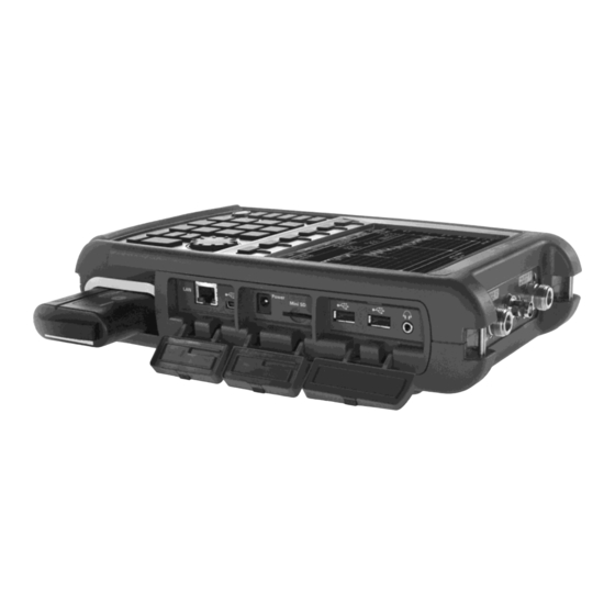
Page 30: Top Panel
Download the latest version of the software at: www.keysight.com/find/fieldfoxsupport Chapter 19, “Using On the N9912A units with serial number prefixes ≥5607, the mini-USB port can be connected to your PC’s standard USB port to send SCPI commands. the Mini-USB Port... - Page 31 Mode. Also used to save files to a USB flash drive. Use of Keyboard and Mouse is NOT supported. Audio output jack for use with SA Mode Tune and Listen. “Saving and Recalling Files” on page 17-2 Keysight N9912-90001 User’s Guide 2- 11...
-
Page 32: Screen Tour
Data / Mem Display (CAT and NA) “All about Limit Lines” Step / FFT (SA) on page 16-14 “Resolution Bandwidth (Res BW)” on page 8-20 Resolution Setting Mode dependent Measurement Start Freq or Distance Mode dependent 2- 12 Keysight N9912-90001 User’s Guide... - Page 33 Settings” on page 18-16 Marker Readout “All about Markers” on page 16-2 Battery Status “Viewing the Battery Charge Status” on page 20-1 Measurement Type (CAT and NA) Reference Level Mode dependent Reference Position Mode dependent Keysight N9912-90001 User’s Guide 2- 13...
-
Page 34: How To Enter Numeric Values
Select Frequency multipliers as follows: — Gigahertz (1e9 Hertz) — Megahertz (1e6 Hertz) Kilohertz (1e3 Hertz) — — Hertz Select Time multipliers as follows: — Seconds — milliseconds (1e–3) — microseconds (1e–6) — nanoseconds (1e–9) — picoseconds (1e-12) 2- 14 Keysight N9912-90001 User’s Guide... -
Page 35: Connector Care
In addition, a dirty or damaged connector can destroy connectors that are mated to it. For this reason, NEVER use a damaged connector. See also http://na.support.keysight.com/pna/connectorcare/Connector_Care.htm Keysight N9912-90001 User’s Guide 2- 15... - Page 36 Preparing for Initial Use of Your New FieldFox Connector Care 2- 16 Keysight N9912-90001 User’s Guide...
-
Page 37: Cat (Cable And Antenna Test) Mode
Keysight Handheld Analyzers N9912A User’s Guide CAT (Cable and Antenna Test) Mode CAT Mode is typically used to test an entire transmission system, from the transmitter to the antenna. This process is sometimes referred to as Line Sweeping. CAT Mode is similar to NA (Network Analyzer) Mode. Learn more in the Supplemental Online Help: http://na.support.keysight.com/fieldfox/help/SupHelp/F... - Page 38 “Calibration for NA, CAT, and VVM Modes” on page 7-1 “All about Markers” on page 16-2 “All about Limit Lines” on page 16-14 “All about Trace Math” on page 16-19 Making 75Ω (ohm) Measurements at the FieldFox Supplemental Online Help: http://na.support.keysight.com/fieldfox/help/SupHelp/FieldFox.htm 3- 2 Keysight N9912-90001 User’s Guide...
-
Page 39: Cat Mode Settings
The higher the trace is on the screen, the more energy being reflected back to the FieldFox. — DTF (VSWR) Distance to Fault in VSWR format. Keysight N9912-90001 User’s Guide 3- 3... -
Page 40: Quick Settings Table
— Full (Default setting) Only the Settings table is shown on the screen. The trace window is temporarily not shown — Left The Settings table is shown to the left of the trace window 3- 4 Keysight N9912-90001 User’s Guide... -
Page 41: Frequency Range
Automatically adjusts the Y-axis to comfortably fit the Min and Max amplitude of the trace on the screen. Autoscale All Autoscales all of the traces on the screen, useful only for dual-trace configurations. 3. Set Scale, Reference Level, and Reference Position: Keysight N9912-90001 User’s Guide 3- 5... -
Page 42: Averaging
When the counter reaches the specified count, then a ‘running average’ of the last N sweeps is displayed. Average Count = 1 means there is NO averaging. 3- 6 Keysight N9912-90001 User’s Guide... -
Page 43: Smoothing
This setting can be changed at any time without affecting calibration accuracy. How to set Single or Continuous — Press Sweep 3. Keysight N9912-90001 User’s Guide 3- 7... -
Page 44: Resolution (Number Of Data Points)
The increase will not be exactly the amount that you enter, as the actual sweep time is the composite of many factors. Measurement speed specifications do NOT apply in Temperature Control Mode. Learn more in “FieldFox High Temperature Protection” on page 2-4 3- 8 Keysight N9912-90001 User’s Guide... -
Page 45: Output Power
— Low Sets output power to approximately –27 dBm, — Man Set output power to an arbitrary value, — Then press Nominal Power. — Then enter a value using the numeric keypad, the arrows, or the rotary knob. Keysight N9912-90001 User’s Guide 3- 9... -
Page 46: Interference Rejection
Interference Rejection [current setting]. — Then choose from the following: — No interference rejection and fastest possible sweep speed — Minimum The lowest level of Interference rejection. — Med ium The medium level of Interference rejection. 3- 10 Keysight N9912-90001 User’s Guide... -
Page 47: Coupled Frequency
Start or Stop frequency is selected, Coupled Frequency is automatically set to OFF. — The DTF measurement is made using the frequencies as determined by the DTF Frequency Mode setting. Learn more in “DTF Measurement Settings” on page 4-19. Keysight N9912-90001 User’s Guide 3- 11... -
Page 48: Return Loss Measurements
A deteriorated cable is not usually apparent in a Distance to Fault measurement, where more obvious and dramatic problems are identified. A Cable Loss measurement is necessary to measure the accumulated losses throughout the length of the cable. 3- 12 Keysight N9912-90001 User’s Guide... -
Page 49: How To Make A 1-Port Cable Loss Measurement
11.Press Trace 6 then Math and Memory then Data->Mem to store the trace into Memory. 12.Remove the LOAD and leave the end of the cable to be tested open. Keysight N9912-90001 User’s Guide 3- 13... -
Page 50: 2-Port Insertion Loss Measurements
— Press Sweep 3, then select a Resolution setting. — Press Cal 5, then press Normalization. Learn more in “Normalize” on page 7-6. — Connect the DUT and view the insertion loss measurement results. 3- 14 Keysight N9912-90001 User’s Guide... - Page 51 CAT (Cable and Antenna Test) Mode 2-Port Insertion Loss Measurements When measuring very long lengths of cable, it may be necessary to increase the sweep time. Learn how on page 3-8. Learn why in the Supplemental Online Help: http://na.support.keysight.com/fieldfox/help/SupHelp/FieldFox.htm Keysight N9912-90001 User’s Guide 3- 15...
- Page 52 CAT (Cable and Antenna Test) Mode 2-Port Insertion Loss Measurements 3- 16 Keysight N9912-90001 User’s Guide...
-
Page 53: Dtf (Distance To Fault) Measurements
Keysight Handheld Analyzers N9912A User’s Guide DTF (Distance to Fault) Measurements CAT Mode Distance to Fault (DTF) measurements are generally used to locate problems, or faults, in a length of cable or transmission line. In this chapter, the cable to be tested is referred to as the DUT (Device Under Test). -
Page 54: How To Make Dtf Measurements
10. Connect the start end of the DUT to the FieldFox. 11. Press Meas Setup 4 then Settings then Next Page. If the Alias-free Range setting is False, then you may see Alias faults on the screen. Learn more page 4-26. 4- 18 Keysight N9912-90001 User’s Guide... -
Page 55: Dtf Measurement Settings
Faults are displayed on the Y-axis in return loss format, expressed as a positive number in dB. — DTF (VSWR) Faults are displayed on the Y-axis in SWR. Learn more about SWR at the FieldFox Supplemental Online Help: http://na.support.keysight.com/fieldfox/help/SupHelp/FieldFox.ht Keysight N9912-90001 User’s Guide 4- 19... -
Page 56: Dtf Start And Stop Distance
— Choose one of the following: — Lowpass Mode The frequency range of a DTF measurement is set automatically based on the Start and Stop Distances. Use Lowpass mode when the DUT is a cable ONLY. 4- 20 Keysight N9912-90001 User’s Guide... -
Page 57: Coupled Frequency
Coupled Frequency When a Return Loss & DTF measurement is present, this setting allows you to have different frequency ranges for each measurement. Learn more on page 3-11. Keysight N9912-90001 User’s Guide 4- 21... -
Page 58: Cable (Correction) Specifications
— Select or create a cable file which contains the cable loss and velocity factor. With a DTF measurement present: — Press Meas Setup 4. — Then DTF Cable Specifications. — Select Cable Corr. 4- 22 Keysight N9912-90001 User’s Guide... - Page 59 Previous / Next Page Quickly scrolls through pages of Freq/Loss data. — Add Data Add a blank Freq/Loss pair to the table, — Delete/Clear then: — Delete Row Remove the selected Freq/Loss pair from the table. Keysight N9912-90001 User’s Guide 4- 23...
- Page 60 Calculated Start = 2.0 MHz Calculated Stop = 3.598 GHz Center Freq = 1.80 GHz The Loss value for the measurement is interpolated from the Freq/Loss pairs at the Center Freq: 1 GHz = 0.1 dB/m 4- 24 Keysight N9912-90001 User’s Guide...
-
Page 61: Window Settings
The DTF Units setting is available ONLY on the DTF Settings table. By default, X-axis units for DTF measurement settings are displayed in Meters. — Select DTF Units. — Then Choose from: — M (meters) — Feet Keysight N9912-90001 User’s Guide 4- 25... -
Page 62: Calculated Dtf Values
When the Alias-free Range = Off, the following procedure will help to determine if a response is true or an alias response: 1. Put a marker on the response in question and note the distance to the fault. 2. Change the start or stop distance. 4- 26 Keysight N9912-90001 User’s Guide... - Page 63 Re-reflections are measured at the FieldFox as mirror images of the original faults. The largest fault is the open end of the cable. To avoid confusion, set the Stop distance shortly after that fault. Keysight N9912-90001 User’s Guide 4- 27...
- Page 64 DTF (Distance to Fault) Measurements DTF Measurement Settings 4- 28 Keysight N9912-90001 User’s Guide...
-
Page 65: Na (Network Analyzer) Mode
Keysight Handheld Analyzers N9912A User’s Guide 5 NA (Network Analyzer) Mode Learn more about NA Mode measurements in the FieldFox Supplemental Online Help: http://na.support.keysight.com/fieldfox/help/SupHelp/FieldFox.htm. In this Chapter “Measurement Selection” on page 5-3 “Parameter Conversion” on page 5-3 “Quick Settings” on page 5-5 “Calibration Settings”... - Page 66 “All about Markers” on page 16-2 “All about Limit Lines” on page 16-14 “All about Trace Math” on page 16-19 Learn how to make 75Ω (ohm) Measurements in the Supplemental Online Help: http://na.support.keysight.com/fieldfox/help/SupHel p/FieldFox.htm 5- 2 Keysight N9912-90001 User’s Guide...
-
Page 67: Na Mode Settings
In NA Mode ONLY, converts the active S-parameter trace to an equivalent impedance (Z), admittance (Y), or reciprocal 1/S-parameter How to select parameter conversions — Press Measure 1. — Then select an S-parameter — Then More. — Then Conversion. Keysight N9912-90001 User’s Guide 5- 3... -
Page 68: Multi-Trace Configurations
— All other trace settings, such as measurement, format, and limit lines, are applied individually to the ACTIVE trace in the same manner as when a single trace is present. 5- 4 Keysight N9912-90001 User’s Guide... -
Page 69: Quick Settings
Both CAT and NA Modes allow you to view and change most relevant settings from a single location. All of these settings are discussed in this chapter and, unless otherwise noted, ALL of these settings can also be made using the standard softkey menus. Keysight N9912-90001 User’s Guide 5- 5... -
Page 70: Calibration Settings
“Port Extensions” on page 5-16. Learn how to calibrate beginning in “Why and When to Calibrate” on page 7-2. The N9912A does NOT support Media Type: Waveguide. How to view and change Calibration Settings — Press Meas Setup 4. — Then Calibration Settings. -
Page 71: Format
– 1). Use Smoothing as the Group Delay aperture. ——Learn how to set Smoothing aperture on “Smoothing” on page 5-12. ——Learn more about Group Delay measurements at the FieldFox Supplemental Online Help: http://na.support.keysight.com/fieldfox/help/SupHelp/FieldF ox.htm Keysight N9912-90001 User’s Guide 5- 7... -
Page 72: Frequency Range
Adjust the Y-axis scale to see the relevant portions of the data trace. The Y-axis is divided into 10 graticules. This setting can be changed at any time without affecting calibration accuracy. How to set Scale — Press Scale / Amptd. 5- 8 Keysight N9912-90001 User’s Guide... -
Page 73: Magnitude Offset
The Magnitude offset setting affects only the active trace. How to set Magnitude Offset — Press Scale / Amptd. — Then More. — Then Magnitude Offset - Offsets the entire data trace by the specified value. Keysight N9912-90001 User’s Guide 5- 9... -
Page 74: Electrical Delay
Improve the d isplay of a phase measurement. This is similar to the way you would change the reference level in an amplitude measurement. Change the phase response to center or align the response on the screen. 5- 10 Keysight N9912-90001 User’s Guide... -
Page 75: Averaging
When the counter reaches the specified count, then a ‘running average’ of the last <n> sweeps is displayed. Keysight N9912-90001 User’s Guide 5- 11... -
Page 76: If Bandwidth
FieldFox screen. How to set Smoothing — Press BW 2. — Then Smoothing ON OFF. — Then Sm. Aperture and enter a value between 0 and 25 (percent) using the numeric keypad. 5- 12 Keysight N9912-90001 User’s Guide... -
Page 77: Single Or Continuous Measure
— Then choose from the following: 101 |201 1001 1601 4001 | 10001. — Using SCPI, Resolution can be set to ANY number of points between 3 and 10001. See the Programming Guide at http://na.support.keysight.com/fieldfox/help/Programming/webhelp/FFP rogrammingHelp.htm Keysight N9912-90001 User’s Guide 5- 13... -
Page 78: Sweep Time
To help prevent damage to your DUT, use caution when changing modes with your DUT connected to the FieldFox test ports. How to set Output Power — Press Meas Setup 4. — Then Output Power. 5- 14 Keysight N9912-90001 User’s Guide... -
Page 79: System Impedance (Z0)
Learn how to make 75Ω measurements at the FieldFox Supplemental Online Help: http://na.support.keysight.com/fieldfox/help/SupHelp/FieldFox.htm How to set System Impedance — Press Meas Setup 4. — Then Settings. — Then scroll to System Z0 and press — Then type either 50 or 75 and press Enter. Keysight N9912-90001 User’s Guide 5- 15... -
Page 80: Port Extensions
— Then enter time value using the numeric keypad, the arrows, or the rotary knob. Press Enter or select a seconds (time) multiplier. You can also set Port Extensions by pressing Meas Setup 4 then Calibration (settings). 5- 16 Keysight N9912-90001 User’s Guide... -
Page 81: Velocity Factor
Loss” in CAT Mode. A Normalization Cal is REQUIRED when making 2-port CAT or NA measurement. For highest accuracy, when measuring the DUT also attach any cable or adapter that was used in the normalization cal. Keysight N9912-90001 User’s Guide 5- 17... -
Page 82: Big Marker Display States (A And B)
Overlayed configurations are allowed. Learn more in “Multi-Trace Configurations” on page 5-4. — Font Size – Choose either Big or Super Big. Super Big marker readout #3 will cover some of the measurement grid. 5- 18 Keysight N9912-90001 User’s Guide... - Page 83 Lin using the standard menu (Meas 1, Format), the setting will show on the display. But if you then use the Big Readout (A | B | OFF) setting, when B is recalled, the Lin setting will be overwritten with the original Log setting. Keysight N9912-90001 User’s Guide 5- 19...
-
Page 84: Increase Dynamic Range
The results you see will depend on the performance of your DUT. With an S21 trace active: 1. With RF OUT (port-2) open, press Trace 6 then Math and Memory then Data->Mem. 2. Re-connect the DUT. 3. Press Data Math then Data-Mem. 5- 20 Keysight N9912-90001 User’s Guide... -
Page 85: Time Domain - Option 010
Keysight Handheld Analyzers N9912A User’s Guide Time Domain – Option 010 With NA Mode, Time Domain Reflectometry (Opt 010), frequency information is used to calculate and display measurements with time as the horizontal display axis. The response values appear separated in time allowing a different perspective of the test device's performance and limitations. - Page 86 Time Domain – Option 010 Gating Settings “Start, Stop, Center, and Span Gate Times” on page 6-10 “Gating Type” on page 6-10 6- 2 Keysight N9912-90001 User’s Guide...
-
Page 87: Overview
“Gating” on page 6-10. Markers that are created on a Time Domain trace can be used to pinpoint the distance of the mismatch from the reference plane. For more information on Time Domain theory, see http://literature.cdn.keysight.com/litweb/pdf/5989-5723EN.pdf Keysight N9912-90001 User’s Guide 6- 3... -
Page 88: Time Domain (Transform) Settings
Time Domain measurements are calculated. Increasing the data points will improve measurement resolution. However, more data points will usually result in slower sweep updates. Set frequency range and points before selecting Stimulus Mode. 6- 4 Keysight N9912-90001 User’s Guide... -
Page 89: Stimulus (Mode)
How to set Start and Stop time — Press Measure 4. — Then Transform. — Then Transform Start Stop. Keysight N9912-90001 User’s Guide 6- 5... -
Page 90: Distance Units
Time Domain response. The Window setting reduces the abruptness of the frequency domain transitions. This causes you to make a trade off in the Time Domain response. 6- 6 Keysight N9912-90001 User’s Guide... -
Page 91: Line Loss And Velocity Factor
Line Loss and Velocity Factor By default, the FieldFox does NOT correct Time Domain measurements to account for the inherent loss of a cable. However, to make more accurate measurements, Line Loss and Velocity Factor should be considered. Keysight N9912-90001 User’s Guide 6- 7... -
Page 92: Data Chain
— Standard – The normal FieldFox data processing chain. Transform calculations are performed AFTER error correction and trace math. — 8510 – The data processing chain used by the Keysight 8510 network analyzer. Transform calculations are performed BEFORE error correction and trace math. -
Page 93: Trace Settings
Gate Enable Enable Gating for the specific trace. — Select the trace. — Press Measure 4. — Then Transform. — Then choose from: — Trace displays Time Domain data. — Trace displays frequency domain data. Keysight N9912-90001 User’s Guide 6- 9... -
Page 94: Gating
The gate start and stop flags on the display point toward the part of the trace you want to keep. Choose from the following: — Bandpass KEEPS the responses within the Gating Start and Stop times. 6- 10 Keysight N9912-90001 User’s Guide... - Page 95 — distorted gate shape that has no passband — distorted shape — incorrect indications of start and stop times — may have increased sidelobe levels. Keysight N9912-90001 User’s Guide 6- 11...
- Page 96 Time Domain – Option 010 Gating 6- 12 Keysight N9912-90001 User’s Guide...
-
Page 97: Calibration For Na, Cat, And Vvm Modes
“Save the Calibration” on page 7-9 “Verify a Calibration” on page 7-10 “Calibration Method Summary” on page 7-11 ECal and Waveguide Calibrations are NOT supported on the N9912A. See Also Learn How to Make 75 ohm Measurements at the FieldFox Supplemental Online Help: http://na.support.keysight.com/fieldfox/help/SupHelp/FieldFox.htm... -
Page 98: Why And When To Calibrate
Calibration Reference Plane is the point at which cal standards are connected during a calibration. This can be either the FieldFox RF OUT connector, or at the end of a jumper cable or adapter. 7- 2 Keysight N9912-90001 User’s Guide... -
Page 99: Preset Calibration (Also Known As Calready)
Press Esc at any time durign the QuickCal to stop the calibration. — In CAT, NA, or VVM Mode, press Cal 5. — Then (if necessary) press Cal Type to see [QuickCal]. — Press Start Cal. No Connection — Disconnect the DUT from the FieldFox. Keysight N9912-90001 User’s Guide 7- 3... - Page 100 — When your DUT has high return loss such as the reject band of a filter. Then measuring the load improves accuracy. Even with the optional Load, phase accuracy begins to degrade when the return loss is greater than about 20dB. 7- 4 Keysight N9912-90001 User’s Guide...
-
Page 101: O, S, L Cal
CAL ON U is shown on the screen when an O,S,L Cal is correcting the measurement. How to perform a O, S, L Cal Keysight N9912-90001 User’s Guide 7- 5... -
Page 102: Normalize
Mode) and a S21 Transmission measurement (NA Mode). One of these measurements must be selected before performing a Normalize Cal. A Normalization Cal is REQUIRED to make accurate 2-port Transmission or Insertion Loss measurements. 7- 6 Keysight N9912-90001 User’s Guide... -
Page 103: Interpolation
Cal ON*. For highest accuracy: a new cal should be performed when the temperature changes more than about 10F (5C), or when the connection to the DUT requires a different jumper cable or adapters. Keysight N9912-90001 User’s Guide 7- 7... -
Page 104: Cal On ? - Questionable Accuracy
However, a 1-port calibration CAN coexist with a 2-port normalization ONLY when BOTH of the following conditions occur: 1. A 1-port Cal already exists, then a Normalization Cal is performed. They can NOT be performed in the reverse order. 7- 8 Keysight N9912-90001 User’s Guide... -
Page 105: Save The Calibration
After performing any type of calibration, you can save the FieldFox settings along with the calibration into a STATE (*.sta) file. These settings and calibration can then be recalled as necessary. To learn how, see “Saving and Recalling Files” on page 17-2. Keysight N9912-90001 User’s Guide 7- 9... -
Page 106: Verifying Calibration And Jumper Cable Integrity
— If the measurement trace is relatively stable, the jumper cable is of good quality. — If you observe significant movement in the peaks of the measurement trace when moving the cable (>5 dB), the jumper cable may need to be replaced. 7- 10 Keysight N9912-90001 User’s Guide... -
Page 107: Calibration Method Summary
— For highest accuracy, a new QuickCal or O,S,L Cal should be performed: — When the temperature changes more than about 10°F (5°C) — When the connection to the DUT requires a different jumper cable or adapters. Keysight N9912-90001 User’s Guide 7- 11... - Page 108 Calibration for NA, CAT, and VVM Modes Calibration Method Summary 7- 12 Keysight N9912-90001 User’s Guide...
-
Page 109: Sa (Spectrum Analyzer) Mode
Keysight Handheld Analyzers N9912A User’s Guide 8 SA (Spectrum Analyzer) Mode SA Mode measures signals at the RF IN port. The RF OUT connector is NOT used. General purpose Spectrum Analyzer measurements are available with Option 230 or 231. SA measurements require NO calibration. - Page 110 “Band/Interval Power Marker” on page 8-33 “Frequency Counter at Marker” on page 8-34 “Audio Beep at Marker Power” on page 8-35 “Channel Measurements” on page 8-37 See Also Interference Analyzer (Opt 236): “Spectrogram Display” on page 9-2 8- 2 Keysight N9912-90001 User’s Guide...
- Page 111 “Waterfall Display” on page 9-5 “How to Record a Session” on page 9-9 Optional Settings: “All about Markers” on page 16-2 “All about Limit Lines” on page 16-14 “Saving and Recalling Files” on page 17-2 Keysight N9912-90001 User’s Guide 8- 3...
-
Page 112: Sa Mode Settings
Span places half of the frequency range on either side of center. When the Center and Frequency Span values are entered, then the X-axis annotation on the screen shows the Center and Span frequencies. 8- 4 Keysight N9912-90001 User’s Guide... - Page 113 Manual to Auto, press CF Step twice. — Manual Type a step size value using the numeric keypad, then select a multiplier key. Learn more in “Multiplier Abbreviations” on page 2-14. Keysight N9912-90001 User’s Guide 8- 5...
-
Page 114: Radio Standard
Radio Standard will be read. Most likely this will be USB or SD Card. — Press Measure 1 OR Freq/Dist then More. — Then Rad io Standard. — Then Import Rad io Standards. 8- 6 Keysight N9912-90001 User’s Guide... -
Page 115: Channel Selection
X-axis. — Freq Span Changes the span of frequencies while the center frequency remains unchanged. — Follow each of the above settings by entering a value using the numeric keypad or the rotary knob. Keysight N9912-90001 User’s Guide 8- 7... -
Page 116: Scale And Units
Adjust the Y-axis scale to see the relevant portions of the data trace. The Y-axis is divided into 10 graticules. A Reference Level is shown on the screen as a solid horizontal bar that can be placed at any graticule. 8- 8 Keysight N9912-90001 User’s Guide... - Page 117 W (watts), V (volts), A (amps), dBmA (dB milliAmps), dBuA (dB microAmps). Antenna correction units are available ONLY by loading or editing an Antenna file that contains the desired units setting. Learn more in “Using the Antenna/Cable Editor” on page 8-13. Keysight N9912-90001 User’s Guide 8- 9...
-
Page 118: External Gain
NOT change. How to set Attenuation The default Attenuation setting is 10 dB. This value can be changed from 0 to 31 dB in 1 dB steps. 8- 10 Keysight N9912-90001 User’s Guide... -
Page 119: Preamplifier Control (Opt 235)
— Increase the RF Attenuation level by 5 dB. —If the signal level does NOT change, then NO compression exists. This indicates that the signal is in the linear region of the FieldFox receiver. Keysight N9912-90001 User’s Guide 8- 11... -
Page 120: Field Strength Measurements
All Correction ON/OFF states survive a Mode Preset, but NOT a Preset. — Press Scale/Amptd. — Then More. — Then Corrections. — Then choose from the following: —Apply Corrections ON OFF Turn ON and OFF correction for all settings. 8- 12 Keysight N9912-90001 User’s Guide... -
Page 121: Using The Antenna/Cable Editor
Using the Antenna/Cable Editor The Antenna Editor and the Cable Editor menus are very similar. Both tables include header information, and a Frequency/Value table. The FieldFox limits Antenna and Cable correction to a maximum of 10001 values. Keysight N9912-90001 User’s Guide 8- 13... - Page 122 ——For both Cable and Antenna correction, Positive numbers indicate loss (we need ADD something positive to compensate for it), and Negative is indicative of some existing gain. 8- 14 Keysight N9912-90001 User’s Guide...
- Page 123 — The FieldFox can also read *.ANT (Antenna) files that were created from older Keysight Spectrum Analyzers. — Data Link does NOT support the SA Mode cable or antenna (*.csv or *.ANT) files.
-
Page 124: Tune & Listen (Am/Fm)
Tune Frequency. See the Listen Time setting for more information. Figure 8-3 Tune & Listen ON In the graphic above, Tune & Listen ON with Tune Frequency is indicated by a vertical bar (highlighted). 8- 16 Keysight N9912-90001 User’s Guide... - Page 125 Tune Frequency to that of the marker. To improve sound quality, try increasing power by reducing the Attenuation setting and, if available, turn ON the Preamplifier. Learn how “Attenuation Control” on page 8-10 Keysight N9912-90001 User’s Guide 8- 17...
-
Page 126: Independent Source
Like a traditional tracking generator, the Independent Source feature can set the internal FieldFox source to track the SA receiver frequency range. It can also set the internal source to a CW frequency that is independent of the SA frequency. 8- 18 Keysight N9912-90001 User’s Guide... - Page 127 Sets the source attenuation from 0 to 31 dB in 1 dB steps. This effectively sets the source output power. While changing the source attenuation, the approximate Nominal Output power is annotated to the right of the active entry setting. Keysight N9912-90001 User’s Guide 8- 19...
-
Page 128: Resolution Bandwidth (Res Bw)
#Res BW x.xx XHz (#) means manual setting. This setting could impact the accuracy of the measurement. See Appendix B:, “Specifications/Data Sheet”. The Res BW setting also affects the Sweep Type setting. Learn how in “Sweep Type” on page 8-21 8- 20 Keysight N9912-90001 User’s Guide... -
Page 129: Video Bandwidth (Video Bw)
FieldFox screen. For a more comprehensive tutorial, see Spectrum Analysis Basics (App Note 150) at http://literature.cdn.keysight.com/litweb/pdf/5952-0292.pdf How to set Sweep Type — Press BW 2. — Then Advanced. — Then Sweep Type Auto FFT Step. Keysight N9912-90001 User’s Guide 8- 21... -
Page 130: Sweep Acquisition
In the graphic above, a GSM signal in a framed data format; timeslot zero ON; all others OFF; PRF = 218Hz, Duty Cycle = 12.5%. The pulsed signal becomes visible on every sweep update with SwpAcquisition = 50. 8- 22 Keysight N9912-90001 User’s Guide... -
Page 131: Very Long Sweep Times
X-axis units becomes Time. The SA becomes like a tunable oscilloscope, with the center frequency being the frequency of interest. This capability is useful for analyzing modulation characteristics, such as pulsed measurements. Keysight N9912-90001 User’s Guide 8- 23... - Page 132 When the sweep time is longer than can be acquired with the current available memory, Meas UNCAL is displayed on the screen. Learn more on page 8-23. Four times the amount of memory is available with the FieldFox A.04.00 release, allowing longer sweep times in Zero Span. 8- 24 Keysight N9912-90001 User’s Guide...
-
Page 133: Triggering
Trigger Settings. — Then Trig Slope. — Then choose from the following: —Pos Sweep is triggered by the rising (positive) edge of signal. —Neg Sweep is triggered by the falling (negative) edge of signal. Keysight N9912-90001 User’s Guide 8- 25... - Page 134 Enter 0 to set Auto Trigger OFF. When Auto Trigger is OFF, the FieldFox does NOT sweep unless a valid External or Video trigger signal is received. — Press Sweep 3. — Then Trigger Settings. 8- 26 Keysight N9912-90001 User’s Guide...
-
Page 135: Single / Continuous / Restart
Points is the number of measured frequencies the X-axis. The higher number of data points, the better the ability to resolve closely spaced signals and the slower the sweep speed. How to set number of points — Press Sweep 3. — Then Points [current setting]. Keysight N9912-90001 User’s Guide 8- 27... -
Page 136: Trace Display States
Trace 4 data WILL be overwritten by the FieldFox when using the Independent Source Normalize feature (“Independent Source” on page 8-18) or using Field Strength antenna or cable corrections (“Field Strength Measurements” on page 8-12). 8- 28 Keysight N9912-90001 User’s Guide... -
Page 137: Average Type
Average Type. For all three of these Trace States, when Sweep 3 Continuous is set to OFF, press Restart to reset the sweep count to 1, perform <n> sweeps, then return to Hold. Keysight N9912-90001 User’s Guide 8- 29... -
Page 138: Detection Method
Figure 8-6 Detection using One Bucket In the graphic above there is one bucket showing Positive peak, Sample, and Negative peak Detection methods. 8- 30 Keysight N9912-90001 User’s Guide... -
Page 139: Display Line
A display line is similar to a Limit Line, except that no PASS/FAIL testing occurs. A display line is easier to create than a Limit Line. Learn more in “All about Limit Lines” on page 16-14. Keysight N9912-90001 User’s Guide 8- 31... -
Page 140: Noise Marker
In addition, when a Noise Marker is displayed, the Detection method is automatically switched to Average and PAvg is shown on the FieldFox screen. This occurs only when Detector is set to Auto. Learn more in “Detection Method” on page 8-30. 8- 32 Keysight N9912-90001 User’s Guide... -
Page 141: Band/Interval Power Marker
— In non-Zero span, a Band Power Marker yields the total power over the specified frequency range. How to measure Band/Interval Power with a marker — Press Marker to create or select a Normal or Delta marker to use to measure Band/Interval Power. — Then press More. Keysight N9912-90001 User’s Guide 8- 33... -
Page 142: Frequency Counter At Marker
CW signal, and read the frequency of the signal peak. However, each frequency count update requires another sweep. If the FieldFox is in HOLD, press Single to update the frequency count results. 8- 34 Keysight N9912-90001 User’s Guide... -
Page 143: Audio Beep At Marker Power
In SA mode, when the current trace does not exactly match the annotation that is on the screen, an asterisk is displayed in the upper-right corner of the screen graticule area. This would occur, for example, when the Res BW setting is Keysight N9912-90001 User’s Guide 8- 35... - Page 144 Hold mode. The annotation is changed immediately, but the trace is not updated until the next sweep occurs. Therefore, the current data trace does not match the screen annotation. See the asterisk in Figure 8-1 on page 8-1. 8- 36 Keysight N9912-90001 User’s Guide...
-
Page 145: Channel Measurements
15 measurements. When enabled, this average setting is automatically making the following ‘averaging’ settings in order to provide the most accurate power measurements: — Averaging Type is set to Power. Keysight N9912-90001 User’s Guide 8- 37... -
Page 146: Traces
Only one measurement trace can be displayed in Channel Measurements. Channel Power (CHP) Channel Power measures total power over the specified Integrated BW. The Integration Bandwidth (IBW) can be adjusted to measure the power over multiple channels. 8- 38 Keysight N9912-90001 User’s Guide... - Page 147 When Channel Power is selected, vertical posts appear on the display to mark the current Integration Bandwidth setting. The displayed Channel Power and Power Spectral Density values are measured and calculated over the specified Integration Bandwidth. Keysight N9912-90001 User’s Guide 8- 39...
- Page 148 The frequency span between the two vertical posts is the Occupied Bandwidth. The Occupied Power, the power that is contained between the two posts, is also displayed in dBm. 8- 40 Keysight N9912-90001 User’s Guide...
- Page 149 Radio Standard in conjunction with channel numbers. Learn how to select a Radio Standard and channels in page 8-6 page 8-7. To change Frequency Span: — Press Freq/Dist . Keysight N9912-90001 User’s Guide 8- 41...
- Page 150 You can measure the channel power in one, two, or three adjacent (offset) channels on the low frequency and high frequency side of the carrier channel. Limits can be used to quickly see if too much power is measured in the adjacent channels. 8- 42 Keysight N9912-90001 User’s Guide...
- Page 151 How to select ACPR — Press Measure__1. — Then Channel Measurements. — Then Ad jacent Channel Power When ACPR is selected, the following settings are maintained from a previous measurement: Center Frequency, Preamp ON|OFF, and RF Attenuation. Keysight N9912-90001 User’s Guide 8- 43...
- Page 152 — Select Offset Integ BW This is the frequency range over which power is measured in that offset; half of the range below and half above the Offset Freq. 8- 44 Keysight N9912-90001 User’s Guide...
- Page 153 - dB or dBc value is computed by subtracting the measured carrier power from the measured offset power. — – dB or dBc value is computed by subtracting the entered RefValue from the measured offset power. —Press Value. Keysight N9912-90001 User’s Guide 8- 45...
- Page 154 RRC Weighting is set and enabled automatically when included in a selected radio standard. To set and enable RRC Weighting: — Press Meas Setup 4. — Then RRC Weighting ON OFF. — Then More. — Then RRC Alpha [current setting]. 8- 46 Keysight N9912-90001 User’s Guide...
- Page 155 SA (Spectrum Analyzer) Mode Channel Measurements — Enter a value between 0 (no smoothing) and 1 (most smoothing) using the numeric keypad, arrows, or the rotary knob. A standard level of filtering is 22. — Press Enter. Keysight N9912-90001 User’s Guide 8- 47...
- Page 156 SA (Spectrum Analyzer) Mode Channel Measurements 8- 48 Keysight N9912-90001 User’s Guide...
- Page 157 Keysight Handheld Analyzers N9912A User’s Guide Interference Analyzer (SA Mode) – Option 236 Option 236 provides Spectrogram display, Waterfall display, and Record/Playback. In this Chapter “Spectrogram Display” on page 9-2 “Common Settings for Waterfall and Spectrogram” on page 9-3 “Waterfall Display” on page 9-5 “About Sessions”...
-
Page 158: Interference Analyzer (Sa Mode) - Option 236
— Frequency Range. Learn more in “Frequency Range” on page 8-4. — Resolution BW and Video BW. Learn more in “Resolution Bandwid th (Res BW)” on page 8-20 “Video Bandwidth (Video BW)” on page 8-21. 9- 2 Keysight N9912-90001 User’s Guide... -
Page 159: Common Settings For Waterfall And Spectrogram
“Average Type” on page 8-29. Common Settings for Waterfall and Spectrogram Set Red and Blue Limits The colors displayed on the Waterfall and Spectrogram represent the various measured power levels: — Red = Highest power levels Keysight N9912-90001 User’s Guide... - Page 160 A indicates the Delta Marker. — At the current sweep speed, the difference in time between these two markers appears at the upper-right corner of the view as Delta Time: hh:mm:ss Sec. 9- 4 Keysight N9912-90001 User’s Guide...
- Page 161 Waterfall display- moderate angle- with time markers 1 minute apart. The following settings all contribute to the sweep time of an individual trace, and therefore, the total elapsed time that can appear on the screen in Waterfall display: Keysight N9912-90001 User’s Guide...
- Page 162 Least detail with highest number of records. — Gradual Most detail with lowest number of records. — Wide Angle Moderate angle with increased space between records. Learn how to “Set Red and Blue Limits” on page 9-3. 9- 6 Keysight N9912-90001 User’s Guide...
-
Page 163: Record/Playback
“Manage Sessions” on page 9-14. You can determine the length of time over which recording can occur by setting the Record Interval (the time between recorded traces) and other settings. Learn more in “Recording Configuration” on page 9-11. Keysight N9912-90001 User’s Guide... - Page 164 Learn about “Field Strength Measurements” on page 8-12. — Frequency Counter at Marker is NOT allowed during Recording or Playback. Learn about this feature in “Frequency Counter at Marker” on page 8-34. 9- 8 Keysight N9912-90001 User’s Guide...
- Page 165 — Is the sweep in HOLD? (upper-left annotation) — Is Recording or Playback Paused? (mid-left annotation) — Is the Record or Playback Interval set too long? (Configuration settings.) How to Record a Session — Press Trace 6. Keysight N9912-90001 User’s Guide...
- Page 166 1 and continues to loop indefinitely. During playback, choose from the following: — Pause Resume Temporarily halts playback. Then choose from the following: — Pause Resume Press to continue playing. 9- 10 Keysight N9912-90001 User’s Guide...
- Page 167 Sets where, in the FieldFox data flow, data is recorded. Learn more in “Record Source” on page 9-13. Choose from the following: — RawMeas Records raw measurement data. — Trace 1,2,3,4 Records data from the corresponding trace in its current state. Keysight N9912-90001 User’s Guide 9-11...
- Page 168 Device location – NOT from the Record Playback Storage Device location. These are two different settings. Learn how to set the Save /Recall Storage Device in “Set File Type and Select Device” on page 17-5. 9- 12 Keysight N9912-90001 User’s Guide...
- Page 169 FieldFox data flow data is recorded and played back. For this discussion, it is important to understand Trace States. Learn more “Trace Display States” on page 8-28. Figure 9-3 FieldFox Data Flow and Record Playback Data Points Keysight N9912-90001 User’s Guide 9-13...
- Page 170 Storage Device to select the media which stores the sessions to be managed. This is a different setting from the Save/Recall Storage Device setting. — Then choose from the following: — Internal FieldFox memory (default). 9- 14 Keysight N9912-90001 User’s Guide...
- Page 171 This session can be played back into any Trace State. For example: Play the Max Hold recording into a Clear/Write trace to see the data exactly as it was recorded. — Press Trace 6 then with Trace = 1 and press State then Clr/Wr. Keysight N9912-90001 User’s Guide 9-15...
- Page 172 Play the Max Hold recording into a Max Hold trace to show the accumulation of “Max Hold” activity over the entire recording. — Press Trace 6 then with Trace = 1 and press State then Hold. — Then Record Player. — Then Play 9- 16 Keysight N9912-90001 User’s Guide...
- Page 173 Keysight Handheld Analyzers N9912A User’s Guide 10 Channel Power Meter Mode - Option 311 Channel Power Meter (also known as CPM or Built-in Power Meter) uses the RF IN connector to make quick and simple power measurements over a selectable frequency span. A power sensor is NOT required.
- Page 174 Learn more about these settings: “Scale” on page 11-5 “Relative and Offset Power Measurements” on page 11-6 “Display Units” on page 11-6 “Averaging” on page 11-7 “Single or Continuous Measure” on page 11-7 “Limits” on page 11-8 10-2 Keysight N9912-90001 User’s Guide...
-
Page 175: Channel Power Meter Mode - Option 311
Center frequency. The size of the frequency step can also be changed. Press CF Step then type a step size value using the numeric keypad, then select a multiplier key. Optionally press. Keysight N9912-90001 User’s Guide 10- 3... -
Page 176: Radio Standard
The following CPM settings are identical to the standard Power Meter settings. To learn about these settings, please refer to the following pages: “Scale” on page 11-5 “Relative and Offset Power Measurements” on page 11-6 10-4 Keysight N9912-90001 User’s Guide... - Page 177 Channel Power Meter Mode - Option 311 CPM Settings “Display Units” on page 11-6 “Averaging” on page 11-7 “Single or Continuous Measure” on page 11-7 “Limits” on page 11-8 Keysight N9912-90001 User’s Guide 10- 5...
- Page 178 Channel Power Meter Mode - Option 311 CPM Settings 10-6 Keysight N9912-90001 User’s Guide...
-
Page 179: Power Meter Mode (Option 302)
Keysight Handheld Analyzers N9912A User’s Guide 11 Power Meter Mode (Option 302) Power Meter measurements are made with Keysight USB power sensors. Power readings are displayed on the FieldFox screen. In this Chapter “Supported Power Sensors” on page 11-2 “How to Connect the Power Sensor” on page 11-2 “Average / Peak”... -
Page 180: Supported Power Sensors
See Also “FOPS Settings” on page 12-5 Supported Power Sensors For a complete list of supported Keysight USB Power Sensors, please visit: www.keysight.com/find/usbsensorsforfieldfox The FieldFox does NOT support the following Keysight USB Power Sensor features: External Triggering (Time Gated Burst Power Measurement), Power Sweep Operation, and Frequency Sweep Operation. -
Page 181: Power Meter Settings
Zeroing The Keysight USB Power Sensors perform Internal Zeroing automatically. Because Keysight USB Power Sensors have an internal switch, Internal Zeroing does NOT require that the power source be turned OFF. For highest measurement accuracy, when measuring power levels below –30 dBm, External Zeroing should be performed. -
Page 182: Frequency
NO warning is shown. Frequency A table of correction factors versus frequency is stored within Keysight Power Sensors. The frequency of the power to be measured is entered in the FieldFox so that the appropriate correction factor can be used. -
Page 183: Scale
100 dBm. Autoscale: Using Autoscale, the current reading is used for the center of the scale, and Min and Max values are set accordingly. — Press Scale / Amptd. — Then More. — Then Autoscale. Keysight N9912-90001 User’s Guide 11-5... -
Page 184: Relative And Offset Power Measurements
Sets Power Meter display to dBm or dB. — Watt (%) Sets Power Meter display to Watts or %. Resolution Resolution sets the number of digits to display after the decimal point on the digital power meter display. 11- 6 Keysight N9912-90001 User’s Guide... -
Page 185: Averaging
When a data trace is displayed, the entire trace is measured, then holds. The Hold annotation changes to an arrow --> while the measurement occurs. — Continuous Makes continuous measurements. This is the typical setting when battery power is not critical. Keysight N9912-90001 User’s Guide 11-7... -
Page 186: Step Detection Mode
— Max Limit OFF ON Toggles the display of the Maximum limit ON and OFF. — Max Limit Value Sets the Maximum limit power value. Power reading higher than this will exceed the limit. 11- 8 Keysight N9912-90001 User’s Guide... -
Page 187: 12 Frequency Offset Using Power Sensor (Fops) - Option
FOPS is accessed through (and requires) Option 302 USB Power Meter Mode. With both options installed, you can send a signal with the FieldFox internal source at one frequency, and measure this signal with a Keysight U-Series USB Power Sensor at another frequency. - Page 188 Frequency Offset Using Power Sensor (FOPS) – Option 208 “Amplitude Markers” on page 12-9 “Trace Math” on page 12-9 See Also “All about Trace Math” on page 16-19 12- 2 Keysight N9912-90001 User’s Guide...
-
Page 189: Overview
— The USB power sensor, with an equally long USB/LAN cable, is connected to the IF Output. USB/LAN extenders are NOT provided with the FieldFox or Keysight USB power sensors. — Conversion gain/loss is measured at power sensor. Keysight N9912-90001 User’s Guide... - Page 190 Frequency Offset Using Power Sensor (FOPS) – Option 208 Overview The dynamic range with FOPS may be significantly different when using various power sensors. In general, the lower frequency range sensors have better dynamic range. 12- 4 Keysight N9912-90001 User’s Guide...
-
Page 191: Fops Settings
— Then Power Meter (USB Sensor). — Then connect a USB Power Sensor to either FieldFox USB port. — For a complete list of supported Keysight USB Power Sensors, please visit: www.keysight.com/find/usbsensorsforfieldfox Measurement Selection — Press Measure 1. — Then choose from the following: —... -
Page 192: Sweep Type And Frequency
Sweep Type and Frequency Set the source and receiver frequencies for the FOPS measurements. The receiver is a Keysight U-Series Power Sensor. These are broadband measurement devices, which means that they measure power over a very wide frequency range. Tables of frequency and power correction factors are stored within the power sensors. - Page 193 Rx = 1 GHz to 2 GHz Positive Offset, RxSwp = (Offs - Src) Src = 2 GHz to 3 GHz Offset = 3.8 GHz Rx = 1.800 GHz to 800 MHz Positive Offset, RxSwp = (Offs + Src) Keysight N9912-90001 User’s Guide 12- 7...
-
Page 194: Power Sensor Settling
Src Nom Power (-15 dBm default setting) Set output power to an arbitrary value at the source CW frequency. Then enter a value using the numeric keypad, the arrows, or the rotary knob. Press Enter 12- 8 Keysight N9912-90001 User’s Guide... -
Page 195: Amplitude Markers
When Trace, then Data -> Mem is pressed, if a Src Power trace is active, then RxPower is actually stored into memory. To Compare Src Power (Input) and Rx Power (Output): 1. Meas Rx Power 2. Store to memory Keysight N9912-90001 User’s Guide 12- 9... - Page 196 Frequency Offset Using Power Sensor (FOPS) – Option 208 FOPS Settings 3. View Data & Memory 4. Meas Src Power. 12- 10 Keysight N9912-90001 User’s Guide...
- Page 197 13 Pulse Measurements Mode – Option 330 Pulsed power meter measurements, available with Option 330, are made with Keysight U2020 X-Series USB Peak Power Sensors. These sensors are capable of detecting, measuring, and storing data from a train of pulses at the RF input.
- Page 198 Many of the features included with the FieldFox Pulse Measurements Mode are discussed in detail in these two documents: — Keysight U2020 X-Series USB Peak Power Sensors Programmer’s Guide. http://literature.cdn.keysight.com/litweb/pdf/U2021-90003.pdf — “Best Practices For Making The Most Accurate Radar Pulse Measurements”...
-
Page 199: Pulse Measurements Mode - Option 330
Pulse Measurements Mode – Option 330 Supported Power Sensors Supported Power Sensors Pulse measurements are made using any of the Keysight U2020 X-Series USB Peak Power Sensors. Zeroing of the U2020 X-Series USB Peak Power Sensors is performed automatically at power up, every 5 seconds, and prior to measuring low level signals. -
Page 200: Pulse Measurement Settings
— Learn how to set “Display Units” on page 11-6. — Learn how to set “Limits” on page 11-8. Frequency / Time How to set Frequency — Press Freq/Dist. — Then choose from the following: 13-4 Keysight N9912-90001 User’s Guide... -
Page 201: Zoom Window
Closes the zoom window. — Zoom Center While monitoring the T within the blue vertical posts on Tr 1, enter a value for the center time using the numeric keypad, the arrows, or the rotary knob. Keysight N9912-90001 User’s Guide 13- 5... -
Page 202: Scale
Averaging is allowed for all pulse measurements. Averaging is performed in the USB Power Sensor before the data is sent to the FieldFox. 13-6 Keysight N9912-90001 User’s Guide... -
Page 203: Video Bandwidth
This setting determines whether the FieldFox continuously queries the USB Power Sensor for data, or only once each time the Single button is pressed. Single to conserve battery power or to allow you to save or analyze specific data. Keysight N9912-90001 User’s Guide 13- 7... -
Page 204: Resolution
USB Power Sensor when it is waiting for a pulse signal at the RF Input (Internal) or a TTL signal at the USB Sensor External Trigger input. How to make Trigger settings — Press Sweep 3. — Then Trigger. 13-8 Keysight N9912-90001 User’s Guide... - Page 205 Used ONLY when Trigger Type = Internal, this setting determines whether the trigger level is set manually or is set to the default level in the USB Power Sensor firmware. — Press Sweep 3. — Then Trigger. Keysight N9912-90001 User’s Guide 13- 9...
- Page 206 Trigger Settings Annotation Trigger settings are annotated on the FieldFox screen as highlighted in the following image: In the previous graphic, the settings are: Trig Level = -10 dBm, Trig Type (Int), Pos Slope (/), Delay 13-10 Keysight N9912-90001 User’s Guide...
-
Page 207: Marker Settings
— Amplitude markers ARE displayed at their previous positions. — Then Ampl Mkr 1 or — Enter a value in dBm for the marker using the numeric keypad, the arrows, or the rotary knob. Keysight N9912-90001 User’s Guide 13- 11... -
Page 208: Marker Search
Select, then set a value in dB. Delta markers are created and placed at the Peak and at the specified value AFTER the Peak. Rise and Fall time in Marker Search uses different criteria than in Auto Analysis and will therefore result in different reported values. 13-12 Keysight N9912-90001 User’s Guide... -
Page 209: Auto Analysis
The rate, in pulses / sec, at which pulses recur. How to enable Auto Analysis — Press Mrk ->/Tools. — Then Auto Analysis. — Then choose from the following: — Analysis OFF — The Analysis values appear below trace 1. Keysight N9912-90001 User’s Guide 13- 13... -
Page 210: Pulse Top
The Tr 1 data trace is displayed in yellow. The memory trace is displayed in blue. How to display data and memory traces — Press Trace 6. 13-14 Keysight N9912-90001 User’s Guide... - Page 211 — Press Data to view only the data trace. — Press Memory to view only the memory trace. — Press Data & Memory to view both the live trace and the stored memory trace. Keysight N9912-90001 User’s Guide 13- 15...
- Page 212 Pulse Measurements Mode – Option 330 Pulse Measurement Settings 13-16 Keysight N9912-90001 User’s Guide...
- Page 213 Keysight Handheld Analyzers N9912A User’s Guide 14 VVM (Vector Voltmeter) Mode - Option 308 VVM Mode measures the electrical length of cables and other devices. The 1-Port Cable Trimming application displays the electrical length in both Magnitude and Phase. The 2-Port Transmission measurement displays Magnitude ONLY.
- Page 214 VVM (Vector Voltmeter) Mode - Option 308 “Single or Continuous Measure” on page 14-7 “Zeroing” on page 14-8 Procedures “1-Port Cable Trimming Measurements ” on page 14-9 “2-Port Transmission Measurements” on page 14-11 14- 2 Keysight N9912-90001 User’s Guide...
-
Page 215: Vvm (Vector Voltmeter) Mode - Option 308
Overview Overview In the FieldFox, both 1-port and 2-port measurement types use a different configuration setup from the HP/Keysight 8508A Vector Voltmeter. Figure 14-2 Typical 8508A measurement configuration –as shown in the 8508A manual. The above block diagram requires an external source and directional coupler to measure the electrical length of a DUT or cable to be trimmed. -
Page 216: Vvm Mode Settings
NOT be changed in VVM Mode. — After using the keypad, select a multiplier key. Learn about multiplier abbreviations in“Multiplier Abbreviations” on page 2-14. 14- 4 Keysight N9912-90001 User’s Guide... -
Page 217: Display Resolution
Generally, the high power setting is used when measuring passive, high-loss devices to place the signal farther from the noise floor. However, for devices that are sensitive to high power levels such as amplifiers, use the Low power setting. Keysight N9912-90001 User’s Guide 14- 5... - Page 218 If you have the USB power sensor feature (Option 302) you can measure the actual output power for your measurement. Refer to “Supported Power Sensors” on page 13-3. 14- 6 Keysight N9912-90001 User’s Guide...
-
Page 219: Averaging
--> while the measurement occurs. — Continuous Makes continuous measurements. This is the typical setting when battery power is not critical. — You can also use Run / Hold +/- to toggle between Single and Continuous. Keysight N9912-90001 User’s Guide 14- 7... -
Page 220: Vvm Calibration
— Open – select to display Phase = 0.0 Deg when zeroed. — Short - select to display Phase = 180.0 Deg when zeroed. — Then Zero — Select Zero OFF to turn zeroing off. 14- 8 Keysight N9912-90001 User’s Guide... -
Page 221: 1-Port Cable Trimming Measurements
5. Connect the Short standard to the RF OUT calibration plane.8 6. Press Trace 6 then Math and Memory. Then Data-> Mem. 7. Connect the Open standard to the RF OUT calibration plane. 8. Press Data Math then Data/Mem. Keysight N9912-90001 User’s Guide 14- 9... - Page 222 6. Carefully trim the cable until the phase shift reads zero. The attached cable’s electrical length is now matched to the reference cable. 7. Repeat steps 4 through 6 for the remaining cables to be trimmed. 14- 10 Keysight N9912-90001 User’s Guide...
-
Page 223: 2-Port Transmission Measurements
5. Connect the DUT as in the diagram above. 6. The displayed magnitude value is the gain of the amplifier. To measure isolation of the amplifier, reverse the connection to the amplifier (RF Out to the amplifier output). Keysight N9912-90001 User’s Guide 14- 11... - Page 224 VVM (Vector Voltmeter) Mode - Option 308 2-Port Transmission Measurements 14- 12 Keysight N9912-90001 User’s Guide...
-
Page 225: Channel Scanner (Sa Only And Option 312)
Keysight Handheld Analyzers N99xxA User’s Guide 15 Channel Scanner (SA Only and Option 312) In this Chapter: “Using Channel Scanner” on page 15-1 “How to Set Up Channel Scanner” on page 15-2 Using Channel Scanner Channel Scanner enables you to do the following: Measure and d isplay channel power vs. -
Page 226: How To Set Up Channel Scanner
Bar ChartV — Bar ChartH — Channel Pow — Strip Chart — Chart Overlay — Scan&Listen 3. Modify scale and specify color bar coding—Modify the scale and assign colors to low and high power channels (bars): Keysight N9912-90001 User’s Guide... - Page 227 — List files are save to-from "CurrentDevice\<UserSelectedFolder>\" — Record-Play files are save-recalled to: "CurrentDevice\<UserSelectedFolder>\" 6. Then Save to *.KML or *.CSV file, Save-Recall Rec-Playback: — Then User Folder Def System — – Sets the default User Folder path: Keysight N9912-90001 User’s Guide...
-
Page 228: How To Define A Channel And Use Channel Scanner
— “Step 3. Modify Scale and the Display Color Bar Settings” on page 15-11 — “Step 4: Enable Data Logging and Record Results” on page 15-12 — “Save 5: Save the Log Results:” on page 15-14 Keysight N9912-90001 User’s Guide... - Page 229 Step 1A: Scan Mode: Range Channel Defined 1. Define some channels: Press Measure > Scan Mode > Range 2. Press Ed it Range and modify table items: — Total Channels — Search Count — Start Channel CF — CF Step Size Keysight N9912-90001 User’s Guide...
- Page 230 Measure > Scan Mode > Custom List 2. Press Ed it Custom List and modify table items: — Add table rows — Then for each row: — Edit Center Frequency (CF) — Edit Integration BW (IBW) Keysight N9912-90001 User’s Guide...
- Page 231 Step 2: Select Display Type Select one of the following display orientations: — Select Display Type—choose: — Bar ChartV — Bar ChartH — Channel Pow — Strip Chart — Chart Overlay — Scan&Listen Keysight N9912-90001 User’s Guide...
- Page 232 Channel Scanner (SA Only and Option 312) How to Set Up Channel Scanner Figure 15-5 Bar Chart Vertical Display Type Figure 15-6 Bar Chart Horizontal Display Type Keysight N9912-90001 User’s Guide...
- Page 233 Channel Scanner (SA Only and Option 312) How to Set Up Channel Scanner Figure 15-7 Channel Power Display Type Figure 15-8 Strip Chart Display Type Keysight N9912-90001 User’s Guide...
- Page 234 Channel Scanner (SA Only and Option 312) How to Set Up Channel Scanner Figure 15-9 Strip Chart Overlay Display Type Figure 15-10 Scan & Listen Display Type Keysight N9912-90001 User’s Guide...
- Page 235 3. And, then press System > Display > Display Colors, to set Indoor, Outdoor, or other display colors. See also Chapter 18, “System Settings.” Figure 15-11 Outdoor Display Colors Keysight N9912-90001 User’s Guide...
- Page 236 — Distance: Store results every “n” meters. GPS must be enabled to store results by distance. Procedure 1. Press Measure > Data Logging > Record Settings > Meas Interval ON (default) 2. Press Interval Type > Time Distance then: Keysight N9912-90001 User’s Guide...
- Page 237 — Optional: Use the RPG (fine adjust) or the arrow keys (coarse adjust) to change the color bar. — Position to change the position along the time record’s results. — Red Limit to change the color bar. Keysight N9912-90001 User’s Guide...
- Page 238 Step 6: Import and Play back KML Files into 3rd Party Software (Example: Google Earth with Animation Tool) Features Use the Playback Slider to replay measurement results. See also Google Maps and or Google Earth’s help. Keysight N9912-90001 User’s Guide...
- Page 239 — Loop mode has a Fast-Slow Replay Option. — Click on each color coded balloon to see the table of measurement results for that location. Figure 15-13 Importing a KML File Into Google Earth Keysight N9912-90001 User’s Guide...
- Page 240 Channel Scanner (SA Only and Option 312) How to Set Up Channel Scanner Keysight N9912-90001 User’s Guide...
- Page 241 Keysight Handheld Analyzers N9912A User’s Guide 16 Data Analysis Features The following features can be used after a measurement to analyze the results. In this Chapter “All about Markers” on page 16-2 “About Delta Markers” on page 16-3 “Marker Table” on page 16-4 “Coupled Markers (NA Mode)”...
-
Page 242: Data Analysis Features
— Then move the marker as when it was first created. — Markers can also be moved using one of the marker search functions. Learn more in “Searching with Markers” on page 16-7. 16- 2 Keysight N9912-90001 User’s Guide... -
Page 243: About Delta Markers
Peak search functions can be performed using delta markers. Figure 16-2 A Delta marker and its associated reference marker. In the graphic above, the marker readout shows the difference between the two markers in frequency and amplitude. Keysight N9912-90001 User’s Guide 16- 3... -
Page 244: Marker Table
6 markers in a full-width window, and up to 3 markers for a half-width window (NA mode). The marker table “squeezes” the graticule area when activated. How to display the Marker table — Press Marker. — Then Marker Table On Off. 16- 4 Keysight N9912-90001 User’s Guide... -
Page 245: Coupled Markers (Na Mode)
Coupled Markers move on ALL traces at the same time. How to create Uncoupled Markers Markers are coupled by default. To create markers that are NOT coupled (move independently on each trace): — Press Marker. — Then More. — Then Coupled Markers OFF Keysight N9912-90001 User’s Guide 16- 5... -
Page 246: Marker Colors
The marker is created on the current Marker Trace selection (default setting is 1). — Then More. — Then select the marker to move using Marker 1,2,3,4,5,6. — Then toggle Marker Trace 1,2,3,4. — The selected marker is moved to the specified trace. 16- 6 Keysight N9912-90001 User’s Guide... -
Page 247: Marker Format
“Format” on page 5-7. Searching with Markers Marker Searches are used to move markers to locations on the trace which exhibits the characteristics of the search criteria. Learn “What Is a ‘Peak’” on page 16-10. Keysight N9912-90001 User’s Guide 16- 7... - Page 248 ——Negative numbers search for a Peak bandpass, such as a filter S21 response. Either of the following TWO methods can be used to search for a Valley or Notch filter, such as the S11 response of a bandpass filter. 16- 8 Keysight N9912-90001 User’s Guide...
- Page 249 S21 of a filter with BW Markers and associated readout values. The search criteria is -3 dB. Figure 16-5 S11 of the same filter with same search criteria: -3 dB. The same values would result from a search criteria of approximately +30.4 Keysight N9912-90001 User’s Guide 16- 9...
-
Page 250: What Is A 'Peak
You define what the FieldFox considers a “peak” by setting the Peak Threshold and Peak Excursion. These two peak criteria settings are set individually for each trace and for each mode (CAT, SA, or NA). 16- 10 Keysight N9912-90001 User’s Guide... - Page 251 Default = 0.5 dB for CAT and NA Modes; 6 dB for SA Mode. For example, the settings for the trace in the following image are: — Threshold: –10 dB — Excursion: 1 dB Keysight N9912-90001 User’s Guide 16- 11...
-
Page 252: Marker Functions
More then: — Mkr=>Start Distance The Start Distance of the measurement becomes the value of the active marker. Markers that would no longer appear on the screen are moved to the new Start Distance. 16- 12 Keysight N9912-90001 User’s Guide... -
Page 253: Sa Marker Functions
The following Marker Functions are available in SA Mode ONLY: — Noise Marker — Band/Interval Power Marker — Frequency Counter at Marker — Audio Beep with Marker Learn more about these marker functions starting in“Noise Marker” on page 8-32. Keysight N9912-90001 User’s Guide 16- 13... -
Page 254: All About Limit Lines
“How to use the FieldFox labeler” on page 17-3. — Fixed/Relative – Press Ed it to toggle between the following: ——Fixed - the limit line does not move. The X/Y coordinates are absolute locations on the screen. 16- 14 Keysight N9912-90001 User’s Guide... -
Page 255: Relative Limit Lines
The limits will then remain a constant Y-axis distance from the Reference Level. Each limit line can be changed at any time from Fixed to Relative, and Relative to Fixed. Keysight N9912-90001 User’s Guide 16- 15... -
Page 256: Build From Trace
— Press Limit 8. — Then — Then Build From Trace. A limit line table appears. — Use the arrows to select ON. — Use Offset to shift the limit line UP or DOWN. Learn how below. 16- 16 Keysight N9912-90001 User’s Guide... -
Page 257: Limit Options
— Press Save/Recall then Device to set the Device (Internal, SD card, or USB flash drive) to be used for the Save or Recall. Learn more in “Set File Type and Select Device” on page 17-5. Keysight N9912-90001 User’s Guide 16- 17... - Page 258 — Then choose from the following: — Save Limits After limit lines have been defined, this saves the line definition to a file on the specified device. — Recall Limits Recalls a limit Line definition from the specified device. 16- 18 Keysight N9912-90001 User’s Guide...
-
Page 259: All About Trace Math
— Then Data Math. — Then choose one of the following: — Data + Mem [D+M] Current measurement data is added to the data in memory. Keysight N9912-90001 User’s Guide 16- 19... -
Page 260: About Math Operations
Data-Mem for Data-Mem for S-parameters absolute power with 20*log levels with relationship 10*log relationship –10 dB and –12 dB 2 dB –24 dB -14dB –50 dB and –52 dB 2 dB –64 dB -54dB 16- 20 Keysight N9912-90001 User’s Guide... -
Page 261: File Management
Keysight Handheld Analyzers N9912A User’s Guide 17 File Management The FieldFox can save any of the following types of files: — Current settings and calibration — Trace data (*.csv, *.kml, and *.S1P) — Picture of the FieldFox screen In addition, files can be saved to the internal memory, a USB Flash drive, or a standardSD card. -
Page 262: Saving And Recalling Files
FieldFox’s internal An example for transferring an image: memory. http://na.support.keysight.com/fieldfox/help/Programming/webhelp/ Examples/Transfer_Image_to_PC.htm. Please note that the receiving computer program needs to be able to handle the binary block transfer. See also FieldFox Programming Guide 17- 2 Keysight N9912-90001 User’s Guide... - Page 263 The preselected keywords (File, Site, and so forth) can be selected just like a single character. These keywords can also be edited. Learn more in “Edit Keywords” on page 17-9. Figure 17-1 The FieldFox labeler Keysight N9912-90001 User’s Guide 17- 3...
-
Page 264: Recall Files
How to Recall a File Before recalling a file, first set File Type to State or Trace + State, and also Select Device from which the file will be recalled. — Press Save/Recall 9. — Then Recall. 17- 4 Keysight N9912-90001 User’s Guide... -
Page 265: Set File Type And Select Device
Saves the current trace and instrument settings to a *.sta file. In SA Mode, all traces are saved. This file can be opened ONLY by a FieldFox. When recalled, the FieldFox sweep is set to Hold. Keysight N9912-90001 User’s Guide 17- 5... - Page 266 Saves CAT and NA Mode trace data to an *.S1P or *.S2P file, depending on the active measurement. This file format is used by CAE programs such as Keysight's Microwave Design System (MDS) and Advanced Design System (ADS). It can also be imported into spreadsheet software such as Microsoft Excel.
-
Page 267: Manage Files
When selecting Internal, it may also be necessary to first select Manage Folders to specify an active folder which contains the files to copy or delete. Refer to “Manage Folders” on page 17-8 — Then More. — Then Manage Files. Keysight N9912-90001 User’s Guide 17- 7... -
Page 268: Manage Folders
A new folder is created in the current folder. Select a name for the new folder from one of the displayed keywords: You can change these keywords using the following Ed it Keywords function. Refer to “Edit Keywords” on page 17-9. 17- 8 Keysight N9912-90001 User’s Guide... -
Page 269: Edit Keywords
When the selected keyword is complete: — Press Done to save all keywords and close the Edit Keywords labeler. These keywords will exist on the FieldFox until changed. — Press Cancel to close the labeler without saving changes. Keysight N9912-90001 User’s Guide 17- 9... -
Page 270: Prefixes For Filenames
When the Prefix is complete — Press Done to save the Prefix and close the labeler. This Prefix will exist on the FieldFox until it is changed. — Press Cancel to close the labeler without saving changes. 17- 10 Keysight N9912-90001 User’s Guide... -
Page 271: Printing
— If necessary, edit the filenames to be printed. — Select Done. Then Print Selected Files to begin printing. ——Print Current Screen – Immediately prints the FieldFox screen using the selected Printer and Page Setup settings. Keysight N9912-90001 User’s Guide 17- 11... - Page 272 File Management Printing 17- 12 Keysight N9912-90001 User’s Guide...
-
Page 273: 18 System Settings
Keysight Handheld Analyzers N99xxA User’s Guide 18 System Settings In this Chapter “Run/Hold” on page 18-2 “Preset” on page 18-3 “User Preset” on page 18-3 “Volume Control” on page 18-4 “Display Settings” on page 18-5 “Display Brightness” on page 18-5 “Display Colors”... -
Page 274: Run/Hold
“Date and Time, Format, and Time Zone Settings” on page 18-16 “LAN Settings” on page 18-18 “Power ON” on page 18-19 “FieldFox Package Installer (N9912A units with serial number prefixes ≥5607 Only)” on page 18-20 “Service Diagnostics” on page 18-22 “System Information”... -
Page 275: Preset
Preset key is pressed. Your custom settings are saved to a standard State file (UserPreset.sta). However, unlike State files, calibration data is NOT saved. Learn more about State files in “Set File Type and Select Device” on page 17-5. Keysight N9912-90001 User’s Guide 18- 3... -
Page 276: How To Set User Preset
The volume control setting remains through a FieldFox Preset. To cause your volume control setting to remain through a FieldFox shut down, save the setting as a Preference. Learn how in “Save and Reset Preferences” on page 18-8. 18- 4 Keysight N9912-90001 User’s Guide... -
Page 277: How To Set Fieldfox Volume Control
0 and 100%. Display Colors Change Display Colors to alter the viewing scheme. How to set Display Colors — Press System 7. — Then Display. Keysight N9912-90001 User’s Guide 18- 5... -
Page 278: Trace Width
A custom title can be made to appear in the upper-left corner of the FieldFox screen. The title can contain up to approximately 65 alpha-numeric characters. To view the Title area, see the “Screen Tour” on page 2-12. 18- 6 Keysight N9912-90001 User’s Guide... -
Page 279: Edit Keywords
Preferences. Learn how in the next section. — From the Quick Settings table. Quick Settings Table All preferences can be set from the Quick Settings table. They are immediately saved as Preferences when Done is pressed. Keysight N9912-90001 User’s Guide 18- 7... -
Page 280: Save And Reset Preferences
All settings that can be saved as preferences (except Battery Saver and Startup Mode) can also be made from individual softkey selections throughout the FieldFox menu structure. However, they remain through a FieldFox shut down ONLY when the current settings are saved as preferences. 18- 8 Keysight N9912-90001 User’s Guide... -
Page 281: Language
Startup Mode The Startup Mode setting determines the mode that becomes active (visible) when User Preset is set to OFF (Factory Preset) and the FieldFox is powered ON. See “User Preset” on page 18-3. Keysight N9912-90001 User’s Guide 18- 9... -
Page 282: Battery Saver
When enabled, FieldFox uses the last selected Device and Folder location as the default device location after instrument power cycle. Before setting the preferences for the File Folders, you must select the Device and Folder locations. Refer to Chapter 17, “File Management”, on page 17-1. 18- 10 Keysight N9912-90001 User’s Guide... -
Page 283: System Configuration
“Options and Features” on page 1-1. How to view the Installed Options — Press System 7. — Then System Configuration. — Then Options (Licensing). — Then Show Options. The currently installed options are listed. Keysight N9912-90001 User’s Guide 18- 11... -
Page 284: Gps
This feature is usable ONLY with the GPS receiver that is shipped with Microsoft “Streets and Trips” and “AutoRoute” (versions 2010 and later). The GPS receiver is NOT available from Keysight. Only the GPS USB receiver is used with the FieldFox. Therefore, it is NOT necessary to purchase the very latest version of the map software. - Page 285 As the bar graph count exceeds 9 bars, the “dB” text is dropped from the number displayed on the bar. Units for C/No are dBHz. Figure 18-1 GPS Display — The left portion of the screen displays satellites and the corresponding number on the adjacent Satellite Power chart. Keysight N9912-90001 User’s Guide 18- 13...
- Page 286 — ddd.ddddddd° decimal degrees — Elevation Unit Choose from: — (Meters) — Feet GPS Status With GPS enabled and a device detected, the following is displayed at the top of the FieldFox screen: 18- 14 Keysight N9912-90001 User’s Guide...
-
Page 287: Frequency Reference Source
— Press System 7. — Then System Configuration. — Then Frequency Ref. — Then Freq Ref Source Int Ext. The FieldFox may take up to 10 seconds to lock to a valid External References source. Keysight N9912-90001 User’s Guide 18- 15... -
Page 288: Security Level
FieldFox screen. The Date and Time is also used to identify files that are saved. The Date and Time can also be set by synchronizing with GPS satellites. Learn more in “GPS” on page 18-12. 18- 16 Keysight N9912-90001 User’s Guide... - Page 289 BEFORE manually setting the Date and Time, be absolutely certain that the Time Zone setting is correct. — Press System 7. — Then System Configuration. — Then Date and Time. — Press the arrows to highlight the row to be edited. Keysight N9912-90001 User’s Guide 18- 17...
-
Page 290: Lan Settings
Software. Learn more about Data Link at: www.keysight.com/find/fieldfoxsupport. Table 18-1 LAN LEDs (N9912A units with serial number prefixes ≥5607 Only) LAN LEDs (N9912A units with serial number prefixes ≥5607 Only) When FieldFox is connected to the LAN, the flashing LAN LEDs have the following definitions: Green: Flashing indicates packets are being transferred. -
Page 291: Power On
Power ON When the FieldFox is without a power source, this setting allows the FieldFox to power ON as soon as a charged battery or the DC Adapter is inserted without pressing the power button. Keysight N9912-90001 User’s Guide 18- 19... -
Page 292: Fieldfox Package Installer (N9912A Units With Serial Number Prefixes ≥5607 Only)
— Manual The FieldFox will power ON only when the power button is pressed. N9912A units with serial number FieldFox Package Installer ( prefixes ≥5607 Only The FieldFox Package Installer enables you to download new versions of firmware from either a USB memory or SD Card. Additionally, the Utility softkey enables you to backup user files or restore user files. - Page 293 If your stored any user files to a USB or SD card, this procedure restores those files. From the initial Installer menu: — Press Utility — Then Cancel to exit without restoring your files and returning to the initial Installer menu. Press Restore Data Keysight N9912-90001 User’s Guide 18- 21...
-
Page 294: Service Diagnostics
Thru connection. The format is P1 <date time>, P2 <date time>, P1-P2 <date time>. The factory calibration is updated when you send your FieldFox to Keysight for Instrument Calibration. Learn more in “Instrument Calibration” on page C-4. - Page 295 — The FieldFox is rebooted, which manages the newly-freed data and re-writes the factory cal kits and cable files. Rebooting is not required on the N9912A units with serial number prefixes ≥5607 models. Keysight N9912-90001 User’s Guide...
- Page 296 System Settings Service Diagnostics 18- 24 Keysight N9912-90001 User’s Guide...
-
Page 297: Using The Mini-Usb Port To Send Scpi Commands And Queries (N9912A Units With Serial Number Prefixes ≥5607 Only)
FieldFox using the VISA connection. Refer to the Keysight Connection Expert Help. — In the Keysight Interactive IO window: Type in your SCPIs on the Command line and click Send Command, Read Response, or Send & Read. Refer to... - Page 298 Using the Mini-USB Port to send SCPI Commands and Queries (N9912A units with serial number prefixes ≥5607 Only) Mini-USB Connection to PC with IO Libraries Figure 19-1 Keysight Interactive IO Window Keysight N9912-90001 User’s Guide...
-
Page 299: 20 Working With The Lithium-Ion Battery
Keysight Handheld Analyzers N9912A User’s Guide 20 Working with the Lithium-Ion Battery In this Chapter “Viewing the Battery Charge Status” on page 20-1 “Charging the Battery” on page 20-3 “Reconditioning Battery” on page 20-6 “Battery Care” on page 20-6 “Maximizing Battery Life” on page 20-6 “Lithium-Ion Battery Disposal”... -
Page 300: Service Diagnostics-Battery Screen
Each lithium ion battery has an LED gauge that displays its charge status. The gauge is active unless the battery is in shut down mode. To view the LED gauge, open the FieldFox battery compartment door, remove the battery, then press the button on the battery. 20- 2 Keysight N9912-90001 User’s Guide... -
Page 301: Charging The Battery
Internal Charging with the AC/DC Adapter Read the safety information in “For the AC/DC Adapter” on page 21-4 Internal charging time for a fully depleted battery is approximately 4 hours with the FieldFox either ON or OFF. Keysight N9912-90001 User’s Guide 20- 3... - Page 302 — FieldFox OFF: Charging is indicated by the FieldFox power LED glowing amber, with its intensity increasing from dim to bright every few seconds. This pattern repeats until the LED turns off when charging is done. Learn more on “Front Panel” on page 2-7. 20- 4 Keysight N9912-90001 User’s Guide...
-
Page 303: Using The External Battery Charger (N9910X-872)
LED charge gauge is being renewed. See “Reconditioning Battery” on page 20-6. Yellow/green Battery is reconditioned Red flashing Error Yellow Standby For more information, refer to the Instruction Manual included with the external battery charger. Keysight N9912-90001 User’s Guide 20- 5... -
Page 304: Reconditioning Battery
Storage temperature limits (20% to 50% relative charge is recommended): Transportation: –20°C to 50°C Within 1 month: –20°C to 45°C Within 6 months: –20°C to 40°C Within 1 year: –20°C to 35°C 20- 6 Keysight N9912-90001 User’s Guide... -
Page 305: Lithium-Ion Battery Disposal
Regulations vary for different countries. Dispose of the battery in accordance with local regulations. Keysight Technologies, through Rechargeable Battery Recycling Corporation (RBRC), offers free and convenient battery recycling options in the U.S. and Canada. - Page 306 Working with the Lithium-Ion Battery Lithium-Ion Battery Disposal 20- 8 Keysight N9912-90001 User’s Guide...
-
Page 307: 21 Safety Considerations
Keysight Handheld Analyzers N9912A User’s Guide 21 Safety Considerations Keysight has designed and tested the FieldFox in accordance with IEC Publication 61010-1Safety Requirements for Electrical Equipment for Measurement, Control and Laboratory Use, and the FieldFox is supplied in a safe condition. The FieldFox is also designed for use in Installation Category II and pollution Degree 2 per IEC 61010-1. -
Page 308: For The Fieldfox
The unit may be used only in the operating conditions and positions specified by the manufacturer. Do not install substitute parts or perform any unauthorized modification to the product. Return the product to Keysight Technologies or a designated repair center for service to ensure that safety features are maintained. - Page 309 Safety Considerations For the FieldFox The measuring terminals on this instrument are designed to be used with external signals described in Measurement Category I, but NOT with external signals described in Categories. Keysight N9912-90001 User’s Guide 21- 3...
-
Page 310: For The Ac/Dc Adapter
No operator serviceable parts inside this product. Do not perform any unauthorized modification to the product. Return the product to Keysight Technologies or a designated repair center for service to ensure that safety features are maintained. Operated at an ambient temperature: 0 to 40°C; full power rating;... - Page 311 The AC/DC adapter is for indoor use only. Never use a modified or damaged charger. Use the original AC–DC adapter ONLY. The AC/DC adapter is designed for use in Installation Category II and Pollution Degree 2 per IEC 61010-1. Keysight N9912-90001 User’s Guide 21- 5...
-
Page 312: For The External Battery Charger (N9910X-872)
For the External Battery Charger (N9910X-872) If charging batteries externally, use the optional external charger available from Keysight, or another SMBus charger of level II or higher. Never use a non–SMBus charger because the battery issues commands over the SMBus to the charger to control the charge rate and voltage. -
Page 313: Battery Protective Functions
4.35 V per cell. Once the overcharge protection is tripped, the voltage across each cell must drop below approximately 4.15 V to reset the protection and permit charging. Keysight N9912-90001 User’s Guide 21- 7... -
Page 314: Passive Protection
Passive Protection Reverse Charging: A reverse protection diode prevents against damage or lost data due to a reverse charge polarity applied to the battery terminals. 21- 8 Keysight N9912-90001 User’s Guide... -
Page 315: Batteries: Safe Handling And Disposal
- both are included. Electrostatic Discharge (ESD) Precautions The FieldFox was constructed in an ESD protected environment. This is because most of the semiconductor devices used in this instrument are susceptible to damage by static discharge. Keysight N9912-90001 User’s Guide 21- 9... - Page 316 FieldFox, may damage the instrument input circuitry. To avoid such damage, it is recommended to dissipate any static charges by temporarily attaching a short to the cable or antenna prior to attaching to the instrument. 21- 10 Keysight N9912-90001 User’s Guide...
-
Page 317: Fieldfox Markings
China RoHS requirements. CAUTION, risk of danger, refer to safety information in manual. Dispose of properly Hot surface - connectors get hot during extended operation, so care must be taken when making connections and disconnections. Keysight N9912-90001 User’s Guide 21- 11... -
Page 318: Battery Markings
Dispose of properly. Do not throw batteries away—collect as small chemical waste. Recycle the old battery properly. Consult local or country regulations related to disposal. Keep battery away from excessive heat. Do not dispose of by burning. UL recognized in Canada and the United States. 21- 12 Keysight N9912-90001 User’s Guide... -
Page 319: Packaging Markings
Mexico and meets Mexico’s safety requirements. Japan’s safety and EMC compliance mark. China’s safety and EMC compliance mark. Taiwan’s safety and EMC compliance mark. Singapore’s safety mark. Korea’s safety and EMC mark. GOST, Russia’s safety and EMC mark. Keysight N9912-90001 User’s Guide 21- 13... -
Page 320: Certification And Compliance Statements
Certification Keysight Technologies, Inc. certifies that this product met its published specifications at the time of shipment from the factory. Keysight Technologies, Inc. further certifies that its calibration measurements are traceable to the United States National Institute of Standards and Technology, to the extent allowed by the Institute's calibration facility, and to the calibration facilities of other International Standards Organization members. -
Page 321: Emc
This equipment is Class A suitable for professional use and is for use in electromagnetic environments outside of the home. Acoustic Statement (European Machinery Directive) Acoustic Noise Emission LpA <70 dB Operator position Normal operation position per ISO 7779 Keysight N9912-90001 User’s Guide 21- 15... - Page 322 Safety Considerations Certification and Compliance Statements 21- 16 Keysight N9912-90001 User’s Guide...
-
Page 323: A:.connector Care Review
The following table contains for tips on connector care. Prior to making connections to your analyzer, carefully review the information about inspecting, cleaning, and gauging connectors. For course numbers about additional connector care instruction, contact Keysight Technologies. A- 1... - Page 324 Cleaning connectors with alcohol shall only be done with the DC power cord removed, in a well-venti- lated area, and with the power to the FieldFox turned OFF. Allow all residual alcohol moisture to evapo- rate, and the fumes to dissipate prior to energizing the instrument. A- 2 Keysight N9912-90001 User’s Guide...
-
Page 325: B:.specifications/Data Sheet
Keysight Handheld Analyzers N9912A User’s Guide Specifications/Data Sheet To ensure the highest accuracy and consistency, the FieldFox Specifications are now stored ONLY at: http://literature.cdn.keysight.com/litweb/pdf/N9912-90006.pdf B- 3... - Page 326 Specifications/Data Sheet Keysight N9912-90001 User’s Guide...
-
Page 327: C:.instrument Calibration
Connector Care. Learn more in Appendix A:, “Connector Care Review,”. How do I Get an Instrument Calibration? To get your Keysight instrument calibrated, send it to one of the Keysight Technologies service centers. Please visit this website to learn how: www.keysight.com/find/calibration. C- 4... -
Page 328: What Are My Choices Of Instrument Calibration
Instrument Calibration What Are My Choices of Instrument Calibration? What Are My Choices of Instrument Calibration? The following types of instrument calibration are available from Keysight Technologies service center: Includes the test data from the calibration and the Keysight Calibration... -
Page 329: D:.korean Battery Safety Translation
Keysight Handheld Analyzers N9912A User’s Guide Korean Battery Safety Translation D- 1... - Page 330 Korean Battery Safety Translation D- 2 Keysight N9912-90001 User’s Guide...
- Page 331 Korean Battery Safety Translation Keysight N9912-90001 User’s Guide D- 3...
- Page 332 Korean Battery Safety Translation D- 4 Keysight N9912-90001 User’s Guide...
- Page 333 Keysight Handheld Analyzers N99xxA User’s Guide Keysight Software End-User Licensing Agreement (EULA)
- Page 334 Keysight Software End-User Licensing Agreement (EULA) Keysight N9912-90001 User’s Guide...
- Page 335 Keysight Software End-User Licensing Agreement (EULA) Keysight N9912-90001 User’s Guide...
- Page 336 Keysight Software End-User Licensing Agreement (EULA) Keysight N9912-90001 User’s Guide...
- Page 337 Antenna Corrections , 8-12, 8-13 Cable (Correction) Measurements 8-11 appendix B , A-1, Specifications connector care review attenuation 8-10 4-22 considerations, safety 21-1 Audio Beep 8-35 cable and antenna test See control, temperature Average Type 8-29 Averaging Keysight N9912-90001 User’s Guide...
- Page 338 NA Mode reference marker 16-4 current prefix 17-10 front panel name files 17-3 edit, enable and disable the Full Screen Mode perform 18-7 current suffix 17-10 normalization Electrical Delay 5-10 O, S, L cal Keysight N9912-90001 User’s Guide...
- Page 339 Markers 17-10 Coupled 16-5 multiplier abbreviations 2-14 icons, battery markers 20-1 16-2 multipliers 2-14 IF Bandwidth Coupled (NA Mode) 16-5 Multi-Trace Configurations NA Mode creating 5-12 16-2 multi-trace configurations delta 14-5 16-3 IF bandwidth moving 16-2 Keysight N9912-90001 User’s Guide...
- Page 340 12-1 9-14 mode stand-by mode 3-12 Points SA mode 8-27 review connector care Startup Mode 2-15 18-9 points, SA mode 8-27 reviewconnector care static charge, dissipate Port Extensions 5-16 RRC Weighting Step Detection Mode 8-46 11-8 Keysight N9912-90001 User’s Guide...
- Page 341 Tune & Listen (AM/FM) 8-16 zero span , 8-23, 8-24 units, DTF, changing Zeroing VVM mode 4-25 14-8 USB keyboard zeroing, external , 1-4, 10-4 11-3 zeroing, VVM mode 14-8 external reference 18-15 User Preset 18-3 User Tags values Keysight N9912-90001 User’s Guide...
- Page 342 Index Keysight N9912-90001 User’s Guide...
- Page 343 Installation Note Xxxxx-xxxxx...
- Page 344 This information is subject to change without notice. © Keysight Technologies 2015, 2017 Edition 2, March 2017 www.keysight.com...
Need help?
Do you have a question about the N9912A and is the answer not in the manual?
Questions and answers