Advertisement
Table of Contents
- 1 Table of Contents
- 2 Do You Have Everything
- 3 The Power Button and LED
- 4 Connector Care
- 5 Battery Usage
- 6 Measure Return Loss (CAT Mode)
- 7 Measure 1-Port Cable Loss (CAT)
- 8 Measure Distance to Fault (CAT)
- 9 Measure S-Parameters (NA Mode)
- 10 Multi-Trace Configurations (NA Mode)9
- 11 Calibration (CAT, NA, VVM)
- 12 Spectrum Analyzer (SA Mode)
- 13 Channel Measurements (SA)
- 14 Record Playback (Opt 236)
- 15 Power Meter Mode
- 16 Save and Recall Files
- Download this manual
Contents
Do you have everything? ..................... 1
Connector Care.....................................2
Battery Usage ...................................... 3
Measure Return Loss (CAT Mode) ...... 4
Measure 1-Port Cable Loss (CAT) ....... 5
Measure Distance to Fault (CAT) ........ 6
Measure S-Parameters (NA Mode) ..... 7
Calibration (CAT, NA, VVM) ............... 10
Spectrum Analyzer (SA Mode) .......... 11
Channel Measurements (SA) ............. 12
Record Playback (Opt 236) ............... 13
Power Meter Mode ............................ 14
Save and Recall Files ......................... 15
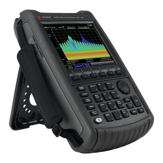
Keysight FieldFox
Microwave Analyzers
Quick Reference Guide
........ 1
Advertisement
Table of Contents

Related Manuals for Keysight FieldFox


Summary of Contents for Keysight FieldFox
-
Page 1: Table Of Contents
Quick Reference Guide Keysight FieldFox Microwave Analyzers Contents Do you have everything? ..... 1 The Power Button and LED ..1 Connector Care……………………………….2 Battery Usage ........3 Measure Return Loss (CAT Mode) ..4 Measure 1-Port Cable Loss (CAT) ..5 Measure Distance to Fault (CAT) .. -
Page 2: Do You Have Everything
FieldFox to devices with various connector types and gender. Attenuators – Reduces power and prevents damage to the FieldFox at the RF IN port. Cal Kit – OSL Tee or other calibration devices. SD card or USB flash drive – Save files to these devices for quick download to a PC. -
Page 3: Connector Care
Connector Care To maintain optimum performance in your FieldFox: Make connections carefully to avoid misalignment, leading to inaccurate measurements of connector damage. Keep the connectors free of dirt and metallic particles. If you must clean the connectors, use clean compressed air first. NEVER use abrasives. When cleaning connectors, use liquid Freon exclusively and apply with a plastic swab. -
Page 4: Battery Usage
Use ONLY a FieldFox charger to recharge a battery. The battery can be fully charged while in the FieldFox in about 4 hours with the FieldFox either ON or OFF. A fully discharged battery takes about 1.5 hours to recharge to 80%. -
Page 5: Measure Return Loss (Cat Mode)
Measure Return Loss (CAT Mode) Starting with A.11.25 firmware, for the B models, the FieldFox output power defaults to -15 dBm. Return loss can be thought of as the absolute value of the reflected power as compared to the incident power. -
Page 6: Measure 1-Port Cable Loss (Cat)
8. Connect the DUT (cable to be tested) to the FieldFox and connect a LOAD at the end of the DUT. Depending on the DUT, the following three steps may improve the amount of ripple visible on the screen. -
Page 7: Measure Distance To Fault (Cat)
8. Press Meas Setup 4 then DTF Cable Specifications. 9. Either press Edit/Save/Recall Cables or enter the Velocity Factor Cable Loss manually--using Cable Corr [Manual]--of the DUT. 10. Connect the start end of the DUT to the FieldFox. The DTF measurement is displayed. -
Page 8: Measure S-Parameters (Na Mode)
Measure S-Parameters (NA Mode) S-parameter syntax is described by the following: S (out | in) out = FieldFox receiver port in = FieldFox source port 1. Press Preset then Preset 2. Press then Mode then then choose from the following: 1-port reflection measurement. - Page 9 Measure S-Parameters (NA Mode) continued The following NA Mode settings can be made before or after calibrating without affecting measurement accuracy. Press Scale/Amptd to change scale. Autoscale Adjusts the Y-axis to comfortably fit the Min and Max amplitude of the active trace. Autoscale All Autoscales all the traces on the screen.
-
Page 10: Multi-Trace Configurations (Na Mode)9
Multi-Trace Configurations (NA Mode) You can display multiple traces on the FieldFox screen. The above image shows a 3-trace configuration. Tr1 is the ACTIVE trace as indicated by the highlighted Tr1 annotation in the upper left corner. The Frequency Range, IF BW, Resolution, Averaging, and Output power is common to all traces. -
Page 11: Calibration (Cat, Na, Vvm)
The Frequency Range, Resolution, Min Swp Time, or Power Level is changed. When using a phase stable jumper cable or adapter to connect the DUT to the FieldFox. These should be high-quality components. Press Cal 5 then see the FieldFox User’s Guide. -
Page 12: Spectrum Analyzer (Sa Mode)
Spectrum Analyzer (SA Mode) SA measurements require NO calibration. Check for a Compressed Measurement 1. Using a marker at the signal peak, make note of the signal power level. 2. Increase the RF Attenuation level by 5 dB. If the signal level does NOT change, then NO compression exists. -
Page 13: Channel Measurements (Sa)
Adjacent Channel Power (ACPR) - Measures the power of a carrier channel and one, two, or three adjacent (offset) channels. Tune and Listen (AM/FM) – Plays potentially interfering AM or FM signals through the FieldFox speaker or headphones. -
Page 14: Record Playback (Opt 236)
Optionally set the following Record Time – limits record time. Record Source – choose where in the FieldFox data flow that data is recorded. RawMeas is easiest. Record Interval – sets the amount of time to wait between individual trace recordings. -
Page 15: Power Meter Mode
Perform external zeroing when measuring power levels below -30 dBm. During external zeroing, the power source MUST either be turned OFF or the power sensor be disconnected from the DUT. Press Cal 5 then see the FieldFox User’s Guide. External Zero Then... -
Page 16: Save And Recall Files
Save and Recall Files Save current settings and calibration, trace data (CSV) and .S1P), or a picture of the FieldFox screen. Press Save/Recall 9 Device 1. Then to set the LOCATION where the file is to be saved. Choose from the following:... - Page 18 This information is subject to change without notice. ©Keysight Technologies 2012-2019 Edition 4 Print Date: June 2019 Supersedes: March 2019 www.keysight.com...
Need help?
Do you have a question about the FieldFox and is the answer not in the manual?
Questions and answers