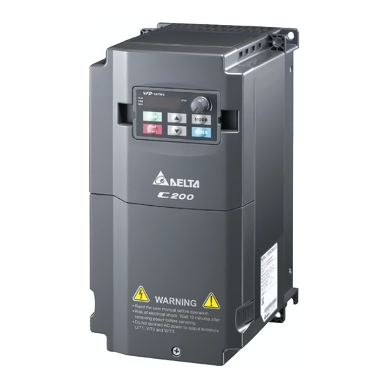
Delta C200 Series User Manual

Delta C200 Series User Manual

Intelligent vector control drive

Advertisement

Call 1(800)985-6929 for Sales
deltaacdrives.com
deltaacdrives.com
sales@deltaacdrives.com

Advertisement

Table of Contents
loading

Summary of Contents for Delta C200 Series

  • Page 1 Call 1(800)985-6929 for Sales deltaacdrives.com sales@deltaacdrives.com Call 1(800)985-6929 for Sales deltaacdrives.com sales@deltaacdrives.com...
  • Page 2 Always read this manual thoroughly before using VFD-C200 series AC Motor Drive, especially the DANGER and CAUTION notes. Failure to comply may result in personal injury and equipment damage. If you have any questions, please contact your dealer.
  • Page 3: Table Of Contents

    Call 1(800)985-6929 for Sales deltaacdrives.com sales@deltaacdrives.com Table of Contents CHAPTER 1 INTRODUCTION......................1-1 CHAPTER 2 INSTALLATION ......................2-1 CHAPTER 3 HOW TO SELECT THE RIGHT AC MOTOR DIRVE..........3-1 CHAPTER 4 WIRING ..........................4-1 CHAPTER 5 MAIN CIRCUIT TERMINALS ..................5-1 CHPATER 6 CONTROL TERMINALS....................6-1 CHAPTER 7 OPTIONAL ACCESSORIES....................7-1 CHAPTER 8 SPECIFICATION ......................8-1 CHAPTER 9 DIGITAL KEYPAD......................9-1...
  • Page 4: Chapter 1 Introduction

    Call 1(800)985-6929 for Sales deltaacdrives.com sales@deltaacdrives.com Chapter 1 Introduction|C200 Series Chapter 1 Introduction Receiving and Inspection After receiving the AC motor drive, please check for the following: Please inspect the unit after unpacking to assure it was not damaged during shipment. Make sure that the part number printed on the package corresponds with the part number indicated on the nameplate.
  • Page 5 Call 1(800)985-6929 for Sales deltaacdrives.com sales@deltaacdrives.com Chapter 1 Introduction|C200 Series Model Name VFD 007 CB 43 A Protection Mode : Blank: standard model M: Enhanced case model 20: IP20/UL Open Type 21: IP20/NEMA1 Installation method Wall mounting Input voltage C200 Series Applicable motor capcity 004:0.5HP(0.375kW)~ 075:10HP(7.5kW)
  • Page 6 Call 1(800)985-6929 for Sales deltaacdrives.com sales@deltaacdrives.com Chapter 1 Introduction|C200 Series RFI Jumper RFI Jumper: The AC motor drive may emit the electrical noise. The RFI jumper is used to suppress the interference (Radio Frequency Interference) on the power line. Frame A0~A Screw Torque: 8 ~10kg-cm(6.9-8.7 lb -in.)
  • Page 7 Call 1(800)985-6929 for Sales deltaacdrives.com sales@deltaacdrives.com Chapter 1 Introduction|C200 Series The gap discharge may occur when the transient voltage is higher than 1,000V. Besides, electro-magnetic compatibility of the AC motor drives will be lower after cutting the RFI jumper. Do NOT cut the RFI jumper when main power is connected to earth.
  • Page 8 Call 1(800)985-6929 for Sales deltaacdrives.com sales@deltaacdrives.com Chapter 1 Introduction|C200 Series Dimensions Frame A0 VFD004CB21A-20; VFD007CB21A-20; VFD004CB23A-20; VFD007CB23A-20; VFD007CB43A-20; VFD015CB43A-20; VFD015CB23A-20 (Fan Module included) Unit: mm [inch] Φ1 Φ2 Φ3 110.0 180.0 160.0 99.6 169.0 151.0 [4.33] [7.09] [6.30] [3,92] [6.65] [5.94]...
  • Page 9 Call 1(800)985-6929 for Sales deltaacdrives.com sales@deltaacdrives.com Chapter 1 Introduction|C200 Series Frame A0 VFD015CB21A-20; VFD022CB21A-20; VFD022CB23A-20; VFD037CB23A-20; VFD022CB43A-20; VFD037CB43A-20; Unit: mm [inch] Φ1 Φ2 Φ3 110.0 180.0 151.0 99.6 169.0 142.0 [4.33] [7.09] [5.94] [3,92] [6.65] [5.59] [0.22] Call 1(800)985-6929 for Sales deltaacdrives.com...
  • Page 10 Call 1(800)985-6929 for Sales deltaacdrives.com sales@deltaacdrives.com Chapter 1 Introduction|C200 Series Frame A0 VFD007CB43A-21; VFD015CB43A-21; VFD004CB23A-21; VFD007CB23A-21; VFD004CB21A-21; VFD007CB21A-21; VFD015CB23A-21 (Fan Module included) Unit: mm [inch] Φ1 Φ2 Φ3 110.0 200.0 160.0 99.6 180.0 169.0 151.0 [4.33] [7.87] [6.30] [3,92] [7.09] [6.65]...
  • Page 11 Call 1(800)985-6929 for Sales deltaacdrives.com sales@deltaacdrives.com Chapter 1 Introduction|C200 Series Frame A0 VFD022CB43A-21; VFD037CB43A-21; VFD022CB23A-21; VFD037CB23A-21; VFD015CB21A-21; VFD022CB21A-21; Unit: mm [inch] Φ1 Φ2 Φ3 110.0 200.0 151.0 99.6 180.0 169.0 142.0 [4.33] [7.87] [5.94] [3,92] [7.09] [6.65] [5.59] [0.22] Call 1(800)985-6929 for Sales deltaacdrives.com...
  • Page 12 Call 1(800)985-6929 for Sales deltaacdrives.com sales@deltaacdrives.com Chapter 1 Introduction|C200 Series Frame A0 VFD004CB21A-21M; VFD004CB23A-21M; VFD007CB21A-21M; VFD007CB23A-21M; VFD007CB43A-21M; VFD015CB43A-21M; VFD015CB23A-21M (Fan Module included) Unit: mm [inch] Φ1 Φ2 Φ3 110.0 200.0 160.0 99.6 180.0 151.0 [4.33] [7.87] [6.30] [3,92] [7.09] [5.94] [0.22]...
  • Page 13 Call 1(800)985-6929 for Sales deltaacdrives.com sales@deltaacdrives.com Chapter 1 Introduction|C200 Series Frame A0 VFD015CB21A-21M; VFD022CB21A-21M; VFD022CB23A-21M; VFD037CB23A-21M; VFD022CB43A-21M; VFD037CB43A-21M; Unit: mm [inch] Φ1 Φ2 Φ3 110.0 200.0 151.0 99.6 180.0 142.0 [4.33] [7.87] [5.94] [3,92] [7.09] [5.59] [0.22] 1-10 Call 1(800)985-6929 for Sales deltaacdrives.com...
  • Page 14 Call 1(800)985-6929 for Sales deltaacdrives.com sales@deltaacdrives.com Chapter 1 Introduction|C200 Series Frame A VFD040CB43A-20; VFD055CB43A-20; VFD075CB43A-20; VFD040CB43A-21; VFD055CB43A-21; VFD075CB43A-21 Unit: mm [inch] Φ1 Φ2 Φ3 130.0 250.0 179.0 116.0 236.0 170.0 22.2 34.0 28.0 [5.12] [9.84] [7.05] [4.57] [9.29] [6.69] [0.24] [0.87]...
  • Page 15 Call 1(800)985-6929 for Sales deltaacdrives.com sales@deltaacdrives.com Chapter 1 Introduction|C200 Series Frame A VFD040CB43A-21M; VFD055CB43A-21M; VFD075CB43A-21M; Unit: mm [inch] Φ1 Φ2 Φ3 130.0 250.0 179.0 116.0 236.0 170.0 22.2 34.0 28.0 [5.12] [9.84] [7.05] [4.57] [9.29] [6.69] [0.24] [0.87] [1.34] [1.10]...
  • Page 16 Call 1(800)985-6929 for Sales deltaacdrives.com sales@deltaacdrives.com Chapter 1 Introduction|C200 Series Digital Keypad KPE-LE02 71.9 [2.83] 25.9 [1.02] 8.6 [0.34] 52.4 [2.06] M3*0.5(2X) 16.3 [0.64] 1.5 [0.06] 61.0 [2.40] 1-13 Call 1(800)985-6929 for Sales deltaacdrives.com sales@deltaacdrives.com...
  • Page 17: Chapter 2 Installation

    Call 1(800)985-6929 for Sales deltaacdrives.com sales@deltaacdrives.com Chapter 2 Installation|C200 Series Chapter 2 Installation Minimum Mounting Clearance and Installation NOTE Prevent fiber particles, scraps of paper, shredded wood saw dust, metal particles, etc. from adhereing to the heat sink Install the AC motor drive in a metal cabinet. When installing one drive below another one, use a metal separation between the AC motor drives to prevent mutual heating and to prevent the risk of fire accident.
  • Page 18 Call 1(800)985-6929 for Sales deltaacdrives.com sales@deltaacdrives.com Chapter 2 Installation|C200 Series Multiple drives side-by-side installation and in rows When installing one AC motor drive below another one (top-bottom installation), use a metal separation between the drives to prevent mutual heating. The temperature measured at the fan’s inflow side must be lower than the temperature measured at the operation side.
  • Page 19 Call 1(800)985-6929 for Sales deltaacdrives.com sales@deltaacdrives.com Chapter 2 Installation|C200 Series NOT E The mounting clearances stated in the figure is for installing the drive in an ※ open area. To install the drive in a confined space (such as cabinet or electric box), please follow the following three rules: (1) Keep the minimum mounting clearances.
  • Page 20 Call 1(800)985-6929 for Sales deltaacdrives.com sales@deltaacdrives.com Chapter 2 Installation|C200 Series Derating Curve Diagram of Normal Duty (Pr.00-16=0) Set Pr.06-55 = 1 Set Pr.06-55 = 0 or 2 (40℃: UL open-type) Set Pr.06-55 = 0 or 2 (30℃: UL type1 or open type_size by size) (50℃: UL open-type)
  • Page 21 Call 1(800)985-6929 for Sales deltaacdrives.com sales@deltaacdrives.com Chapter 2 Installation|C200 Series Derating Curve Diagram of Heavy Duty (Pr.00-16=1) Set Pr.06-55 = 1 Set Pr.06-55 = 0 or 2 (40℃: UL open-type) Set Pr.06-55 = 0 or 2 (30℃: UL type1 or open type_size by size) (50℃: UL open-type)
  • Page 22 Call 1(800)985-6929 for Sales deltaacdrives.com sales@deltaacdrives.com Chapter 3 How to Select the Right AC Motor Drive|C200 Series Chapter 3 How to Select the Right AC Motor Drive The choice of the right AC motor drive for the application is very important and has great influence on its lifetime.
  • Page 23 Call 1(800)985-6929 for Sales deltaacdrives.com sales@deltaacdrives.com Chapter 3 How to Select the Right AC Motor Drive|C200 Series 3-1 Capacity Formulas 1. When one AC motor drive operates one motor The starting capacity should be less than 1.5x rated capacity of AC motor drive The starting capacity= ⎛...
  • Page 24 Call 1(800)985-6929 for Sales deltaacdrives.com sales@deltaacdrives.com Chapter 3 How to Select the Right AC Motor Drive|C200 Series Symbol explanation : Motor shaft output for load (kW) η : Motor efficiency (normally, approx. 0.85) ϕ : Motor power factor (normally, approx. 0.75)
  • Page 25 Call 1(800)985-6929 for Sales deltaacdrives.com sales@deltaacdrives.com Chapter 3 How to Select the Right AC Motor Drive|C200 Series 3-2 General Precaution Selection Note When the AC Motor Drive is connected directly to a large-capacity power transformer (600kVA or above) or when a phase lead capacitor is switched, excess peak currents may occur in the power input circuit and the converter section may be damaged.
  • Page 26 Explosion-proof (Ex) motor: Needs to be installed in a safe place and the wiring should comply with the (Ex) requirements. Delta AC Motor Drives are not suitable for (Ex) areas with special precautions. Gear reduction motor: The lubricating method of reduction gearbox and speed range for continuous operation will be Call 1(800)985-6929 for Sales deltaacdrives.com...
  • Page 27 Call 1(800)985-6929 for Sales deltaacdrives.com sales@deltaacdrives.com Chapter 3 How to Select the Right AC Motor Drive|C200 Series different and depending on brand. The lubricating function for operating long time at low speed and for high-speed operation needs to be considered carefully.
  • Page 28: Chapter 4 Wiring

    Call 1(800)985-6929 for Sales deltaacdrives.com sales@deltaacdrives.com Chapter 4 Wiring|C200 Series Chapter 4 Wiring After removing the front cover, examine if the power and control terminals are clearly noted. Please read following precautions before wiring. Make sure that power is only applied to the R/L1, S/L2, T/L3 terminals. Failure to comply may result in damage to the equipments.
  • Page 29 Call 1(800)985-6929 for Sales deltaacdrives.com sales@deltaacdrives.com Chapter 4 Wiring|C200 Series Wiring Diagram * It provides 1-phase/3-phase power Please refer to chapter 5 Main Circuit Terminals Fuse/NFB(No Fuse Breaker) +1/DC+ R(L1) R(L1) Motor U(T1) S(L2) S(L2) V(T2) T(L3) T(L3) W(T3) It is recommended to install a...
  • Page 30 Call 1(800)985-6929 for Sales deltaacdrives.com sales@deltaacdrives.com Chapter 4 Wiring|C200 Series Figure 1 SINK(NPN)/SOURCE(PNP)Mode Sink Mode Sourc e Mode with internal power (+24VDC ) with internal pow er (+24VDC) +2 4V internal c irc ui t internal c irc ui t...
  • Page 31: Chapter 5 Main Circuit Terminals

    Call 1(800)985-6929 for Sales deltaacdrives.com sales@deltaacdrives.com Chapter 5 Main Circuit Terminals|C200 Series Chapter 5 Main Circuit Terminals Main Circuit Diagram For frame A0 Brake resistor (optional) * Provide 1-phase/3-phase input power Fuse/NFB(No Fuse Breaker) R(L1) U(T1) Motor R(L1) S(L2) V(T2)
  • Page 32 Call 1(800)985-6929 for Sales deltaacdrives.com sales@deltaacdrives.com Chapter 5 Main Circuit Terminals|C200 Series Main power terminals Do not connect 3-phase model to one-phase power. R/L1, S/L2 and T/L3 has no phase-sequence requirement, it can be used upon random selection. It is recommend to add a magnetic contactor (MC) to the power input wiring to cut off power quickly and reduce malfunction when activating the protection function of the AC motor drive.
  • Page 33 Call 1(800)985-6929 for Sales deltaacdrives.com sales@deltaacdrives.com Chapter 5 Main Circuit Terminals|C200 Series avoid this, it is recommend to use a serial connected AC input reactor(6%) at the AC Motor Drive mains input side to reduce the current and improve the input power efficiency.
  • Page 34 Call 1(800)985-6929 for Sales deltaacdrives.com sales@deltaacdrives.com Chapter 5 Main Circuit Terminals|C200 Series 5-1 Main Circuit Terminals Frame A0 Main circuit terminals: R/L1, S/L2, T/L3, U/T1, V/T2, W/T3, , DC+, DC-, B1, B2 Max. Wire Torque Models Min. Wire Gauge Gauge (±10%)
  • Page 35 Call 1(800)985-6929 for Sales deltaacdrives.com sales@deltaacdrives.com Chapter 5 Main Circuit Terminals|C200 Series Frame A Main circuit terminals R/L1, S/L2, T/L3, U/T1, V/T2, W/T3, , DC+(+2,+1), DC-, B1, B2 Max. Wire Torque Models Min. Wire Gauge Gauge (±10%) VFD040CB43A-20/-21/-21M 10 AWG (5.3mm...
  • Page 36 Call 1(800)985-6929 for Sales deltaacdrives.com sales@deltaacdrives.com Chapter 6 Control Terminals|C200 Series Chapter 6 Control Terminals Please remove the top cover before wiring the multi-function input and output terminals, The drive appearances shown in the figures are for reference only, a real drive may look different.
  • Page 37 Call 1(800)985-6929 for Sales deltaacdrives.com sales@deltaacdrives.com Chapter 6 Control Terminals|C200 Series Put back the cover then fasten tightly the screw. Screw torque (M3): 6-8Kg-cm(5.2-6.9lb-in.) Control Terminal the sketch map Frame A0 setting of terminal resistor 0-10V 0/4-20mA 120Ω RB1 RC1...
  • Page 38 Call 1(800)985-6929 for Sales deltaacdrives.com sales@deltaacdrives.com Chapter 6 Control Terminals|C200 Series Wiring precautions: Reserves 5mm and properly install the wire into the terminal; fasten the installation by a slotted screwdriver. If the wire is stripped, sort the wire before install into the terminal.
  • Page 39 Call 1(800)985-6929 for Sales deltaacdrives.com sales@deltaacdrives.com Chapter 6 Control Terminals|C200 Series Terminals Terminal Function Factory Setting (NPN mode) Potentiometer power supply +10V Analog frequency setting: +10Vdc 20mA Analog voltage input Impedance: 20kΩ Range: 0~10V/0~20mA/ 4~20mA(Pr.03-38) +10V AVI circuit =0~Max. Output Frequency (Pr.01-00)
  • Page 40 Call 1(800)985-6929 for Sales deltaacdrives.com sales@deltaacdrives.com Chapter 6 Control Terminals|C200 Series AVI/ACI/AUI AC M ferrite core Wind each wires 3 times or more around the core Digital inputs (FWD, REV, MI1~MI8, COM) When using contacts or switches to control the digital inputs, please use high quality components to avoid contact bounce.
  • Page 41 Call 1(800)985-6929 for Sales deltaacdrives.com sales@deltaacdrives.com Chapter 6 Control Terminals|C200 Series Sink Mode Internal power supply(+24Vdc) +24V MI7/MI8 A B / 0V mode encoder C200 external term inal +24V external power supply 5. Since MI1~MI8 shares the same COM, therefore when using a PG card, MI~MI6 can only be applied at SINK MODE.
  • Page 42: Chapter 7 Optional Accessories

    Call 1(800)985-6929 for Sales deltaacdrives.com sales@deltaacdrives.com Chapter 7 Optional Accessories|C200 Series Chapter 7 Optional Accessories The optional accessories listed in this chapter are available upon request. Installing additional accessories to your drive would substantially improves the drive’s performance. Please select an applicable accessory according to your need or contact the local distributor for suggestion.
  • Page 43 Call 1(800)985-6929 for Sales deltaacdrives.com sales@deltaacdrives.com Chapter 7 Optional Accessories |C200 Series All Brake Resistors and Brake Units Used in AC Motor Drives 230V 1-phase Applicable 125%Braking Torque 10%ED Max. Brake Torque Motor Total Braking Braking Resistor Resistor value Max. Total Braking Min.
  • Page 44 If damage to the drive or other equipment is due to the fact that the brake resistors and brake modules in use are not provided by Delta, the warranty will be void. Take into consideration the safety of the environment when installing the brake resistors. If the minimum resistance value is to be utilized, consult local dealers for the calculation of Watt figures.
  • Page 45 Call 1(800)985-6929 for Sales deltaacdrives.com sales@deltaacdrives.com Chapter 7 Optional Accessories |C200 Series Non-fuse Circuit Breaker Comply with UL standard: Per UL 508, paragraph 45.8.4, part a, The rated current of the breaker shall be 2~4 times of the maximum rated input current of AC motor drive.
  • Page 46 Call 1(800)985-6929 for Sales deltaacdrives.com sales@deltaacdrives.com Chapter 7 Optional Accessories|C200 Series Fuse Specification Chart Use only the fuses comply with UL certificated. Use only the fuses comply with local regulations. Model Manufacturer Class / Catalog No Rating VFD004CB21A-20/-21/-21M Class _T / JJN-15...
  • Page 47 Call 1(800)985-6929 for Sales deltaacdrives.com sales@deltaacdrives.com Chapter 7 Optional Accessories |C200 Series AC Reactor When the AC Motor Drive is connected directly to a large-capacity power transformer (600kVA or above) or when a phase lead capacitor is switched, excess peak currents may occur in the power input circuit due to the load changes and the converter section may be damaged.
  • Page 48 Call 1(800)985-6929 for Sales deltaacdrives.com sales@deltaacdrives.com Chapter 7 Optional Accessories|C200 Series Correct wiring: reactor motor AC motor drive motor AC motor drive motor AC motor drive Application 2 Silicon rectifier and AC motor drive are connected to the same power.
  • Page 49 Call 1(800)985-6929 for Sales deltaacdrives.com sales@deltaacdrives.com Chapter 7 Optional Accessories |C200 Series Zero Phase Reactors RF220X00A UNIT: mm (inch) Diagram A Recommended Cable Wind each wire around the core for 4 times. The reactor Wire Size (mm Wiring type Qty.
  • Page 50 All electrical equipment, including AC motor drives, will generate high-frequency/low-frequency noise and will interfere with peripheral equipment by radiation or conduction when in operation. By using an EMI filter with correct installation, much interference can be eliminated. It is recommended to use DELTA EMI filter to have the best interference elimination performance.
  • Page 51 Call 1(800)985-6929 for Sales deltaacdrives.com sales@deltaacdrives.com Chapter 7 Optional Accessories |C200 Series 1. Use the cable with shielding (double shielding is the best). 2. The shielding on both ends of the motor cable should be grounded with the minimum length and maximum contact area.
  • Page 52 Call 1(800)985-6929 for Sales deltaacdrives.com sales@deltaacdrives.com Chapter 7 Optional Accessories|C200 Series NOTE Never connect phase lead capacitors or surge absorbers to the output terminals of the AC motor drive. If the length is too long, the stray capacitance between cables will increase and may cause leakage current. It will activate the protection of over current, increase leakage current or not insure the correction of current display.
  • Page 53 Call 1(800)985-6929 for Sales deltaacdrives.com sales@deltaacdrives.com Chapter 7 Optional Accessories |C200 Series Digital Keypad KPC-CC01 KPC-CE01 Communication Interface RJ-45 (socket)、RS-485 interface; Installation Method Embedded type and can be put flat on the surface of the control box. The front cover is water proof.
  • Page 54 Call 1(800)985-6929 for Sales deltaacdrives.com sales@deltaacdrives.com Chapter 7 Optional Accessories|C200 Series Function Key It has the factory setting function and the function can be set by the user. The present factory setting: F1 is JOG function. Other functions must be defined by TPEditor first. TPEditor software V1.30.6 is available for download at: http://www.delta.com.tw/ch/product/em/download/download_main.asp?act=3&pid=1&cid=1&tp...
  • Page 55 Call 1(800)985-6929 for Sales deltaacdrives.com sales@deltaacdrives.com Chapter 7 Optional Accessories |C200 Series Panel Mounting (MKC-KPPK) For MKC-KPPK model, user can choose wall mounting or embedded mounting, protection level is IP56. Applicable to the digital keypads (KPC-CC01 & KPC-CE01). Wall Mounting...
  • Page 56 Call 1(800)985-6929 for Sales deltaacdrives.com sales@deltaacdrives.com Chapter 7 Optional Accessories|C200 Series RJ45 Extension Lead for Digital Keypad (Designed only for KEYPAD,NOT for CANopen communication) Part # Description CBC-K3FT 3 feet RJ45 extension lead (approximately 0.9m) CBC-K5FT 5 feet RJ45 extension lead (approximately 1.5 m) CBC-K7FT 7 feet RJ45 extension lead (approximately 2.1 m)
  • Page 57 Call 1(800)985-6929 for Sales deltaacdrives.com sales@deltaacdrives.com Chapter 7 Optional Accessories |C200 Series Fan Kit Frames of the fan kit Model『MKCB-AFKM1』This fan is a12Vdc ON/OFF control fan. Applicable Model VFD015CB21A-20/-21/-21M; VFD022CB21A-20/-21/-21M; VFD022CB23A-20/-21/-21M; VFD037CB23A-20/-21/-21M; VFD022CB43A-20/-21/-21M; VFD037CB43A-20/-21/-21M; VFD040CB43A-20/-21/-21M; VFD055CB43A-20/-21/-21M; Model『MKCB-A0FKM』 Model『MKCB-AFKM2』 This fan is a12Vdc ON/OFF control fan.
  • Page 58 Call 1(800)985-6929 for Sales deltaacdrives.com sales@deltaacdrives.com Chapter 7 Optional Accessories|C200 Series Frame A0 Applicable model VFD015CB23A-20/-21/-21M; 1) Disconnect the power terminal before removing the fan. (As shown below.) 2) Loosen the two screws to remove the fan. Frame A Applicable model VFD040CB43A-20/-21/-21M;...
  • Page 59 Call 1(800)985-6929 for Sales deltaacdrives.com sales@deltaacdrives.com Chapter 7 Optional Accessories |C200 Series USB/RS-485 Communication Interface IFD6530 Warning Please thoroughly read this instruction sheet before installation and putting it into use. The content of this instruction sheet and the driver file may be revised without prior notice. Please consult our distributors or download the most updated instruction/driver version at http://www.delta.com.tw/product/em/control/cm/control_cm_main.asp...
  • Page 60 MKCB-HUB01 Multi-Function Communication Expansion Card In order to coordinate with the integrity of parallel communication between RS485 and CANopen, Delta has introduced a multi-function communication expansion card. Via RS-232 communication port of a computer, connect RS232/RS485 communication interface to any terminal of a communication board MKCB-HUB01. Then connect parallely to one or more VFDs to di multi-function communication control.
  • Page 61 Call 1(800)985-6929 for Sales deltaacdrives.com sales@deltaacdrives.com Chapter 7 Optional Accessories |C200 Series CANopen communication cable Model #: TAP-CB03, TAP-CB04 Title Part No. inch TAP-CB03 500 ± 10 19 ± 0.4 TAP-CB04 39 ± 0.4 1000± 10 Dimensions Unit: mm [inch]...
  • Page 62: Chapter 8 Specification

    Call 1(800)985-6929 for Sales deltaacdrives.com sales@deltaacdrives.com Chapter 8 Specification |C200 Series Chapter 08 Specification 230V Series -1 Phase Frame Size Model VFD -_ _ _CB21A-_ _ _ 0.75 Applicable Motor Output (kW) Applicable Motor Output (HP) Rated Output Capacity (kVA) Rated Output Current (A) rated output current is 120% for 60 seconds;...
  • Page 63 Call 1(800)985-6929 for Sales deltaacdrives.com sales@deltaacdrives.com 460V Series Frame Size Model VFD-_ _ _CB43A-_ _ _ 0.75 Applicable Motor Output (kW) Applicable Motor Output (HP) Rated Output Capacity (kVA) Rated Output Current (A) 10.5 rated output current is 120% for 60 seconds; Overload Tolerance rated output current is 160% for 3 seconds Max.
  • Page 64 Call 1(800)985-6929 for Sales deltaacdrives.com sales@deltaacdrives.com Chapter 8 Specification |C200 Series Environment for Operation, Storage and Transportation DO NOT expose the AC motor drive in the bad environment, such as dust, direct sunlight, corrosive/inflammable gasses, humidity, liquid and vibration environment. The salt in the air must be less than 0.01mg/cm every year.
  • Page 65: Chapter 9 Digital Keypad

    Call 1(800)985-6929 for Sales deltaacdrives.com sales@deltaacdrives.com |C200 Chapter 9 Digital Keypad Chapter 9 Digital Keypad Description of the Digital Keypad KPE-LE02 RUN Key MODE Start AC drive operation. Change between different display mode. STOP/RESET ENTER Stops AC drive operation and reset the drive Used to enter/modify programming after fault occurred.
  • Page 66 Call 1(800)985-6929 for Sales deltaacdrives.com sales@deltaacdrives.com Chapter 9 Digital Keypad|C200 Series External Fault. Display “End” for approximately 1 second if input has been accepted by pressing key. After a parameter value has been set, the new value is automatically stored in memory. To modify an entry, use the keys.
  • Page 67 Call 1(800)985-6929 for Sales deltaacdrives.com sales@deltaacdrives.com |C200 Chapter 9 Digital Keypad How to Operate the Digital Keypad Setting Mode START GO STA RT NOTE: In the selection mode, press to set the parameters. Setting parameters Success to Input data error set parameter.
  • Page 68 Call 1(800)985-6929 for Sales deltaacdrives.com sales@deltaacdrives.com Chapter 9 Digital Keypad|C200 Series Reference Table for the 7-segment LED Display of the Digital Keypad Number Seven Segment Display English letter - - - - Seven Segment Display English letter - - Seven Segment Display English letter -...
  • Page 69 Call 1(800)985-6929 for Sales deltaacdrives.com sales@deltaacdrives.com Chapter 10 Summary of Parameter Settings|C200 Series Chapter 10 Summary of Parameter Settings This chapter provides summary of parameter settings for user to gather the parameter setting ranges, factory settings and set parameters. The parameters can be set, changed and reset by the digital keypad.
  • Page 70 Call 1(800)985-6929 for Sales deltaacdrives.com sales@deltaacdrives.com Chapter 10 Summary of Parameter Settings|C200 Series Factory Parameter Explanation Settings Setting 14: Display the temperature of IGBT in oC (i.) 15: Display the temperature of capacitance in oC (c.) 16: The status of digital input (ON/OFF) (i)
  • Page 71 Call 1(800)985-6929 for Sales deltaacdrives.com sales@deltaacdrives.com Chapter 10 Summary of Parameter Settings|C200 Series Factory Parameter Explanation Settings Setting Bit 0: Control command by PLC force contro Read 00-19 PLC Command Mask only Bit 1: Frequency command by PLC force contro...
  • Page 72 Call 1(800)985-6929 for Sales deltaacdrives.com sales@deltaacdrives.com Chapter 10 Summary of Parameter Settings|C200 Series Factory Parameter Explanation Settings Setting 0: Digital keypad 1: External terminals. Keypad STOP disabled. Source of the Operation 00-31 2: RS-485 serial communication. Keypad STOP Command (HAND)...
  • Page 73 Call 1(800)985-6929 for Sales deltaacdrives.com sales@deltaacdrives.com Chapter 10 Summary of Parameter Settings|C200 Series 01 Basic Parameters Factory Parameter Explanation Settings Setting 60.00/ 01-00 Max. Operation Frequency 0.00~600.00Hz 50.00 60.00/ 01-01 Output Frequency of Motor 1 0.00~600.00Hz 50.00 230V: 0.0V~255.0V 200.0...
  • Page 74 Call 1(800)985-6929 for Sales deltaacdrives.com sales@deltaacdrives.com Chapter 10 Summary of Parameter Settings|C200 Series Factory Parameter Explanation Settings Setting Skip Frequency 2 (upper limit) 01-30 0.00~600.00Hz 0.00 Skip Frequency 2 (lower limit) 01-31 0.00~600.00Hz 0.00 Skip Frequency 3 (upper limit) 01-32 0.00~600.00Hz...
  • Page 75 Call 1(800)985-6929 for Sales deltaacdrives.com sales@deltaacdrives.com Chapter 10 Summary of Parameter Settings|C200 Series 02 Digital Input/Output Parameters Factory Parameter Explanation Settings Setting 0: 2-wire mode, power on for operation control 2-wire/3-wire Operation 02-00 1: 2-wire mode 2, power on for operation control...
  • Page 76 Call 1(800)985-6929 for Sales deltaacdrives.com sales@deltaacdrives.com Chapter 10 Summary of Parameter Settings|C200 Series Factory Parameter Explanation Settings Setting 50: Master dEb action input 51: Selection for PLC mode bit0 52: Selection for PLC mode bit1 53: Trigger CANopen quick stop...
  • Page 77 Call 1(800)985-6929 for Sales deltaacdrives.com sales@deltaacdrives.com Chapter 10 Summary of Parameter Settings|C200 Series Factory Parameter Explanation Settings Setting 30: Output when frequency <= Pr.02-34 (<= 02-34) 31: Y-connection for the motor coil 32: △-connection for the motor coil 33: Zero speed (actual output frequency) 34: Zero speed include stop(actual output frequency) 35: Error output selection 1(Pr.06-23)
  • Page 78 Call 1(800)985-6929 for Sales deltaacdrives.com sales@deltaacdrives.com Chapter 10 Summary of Parameter Settings|C200 Series Factory Parameter Explanation Settings Setting Status of Multi-function Read 02-51 Monitor the status of multi-function output terminals Output Terminal only Display External Output Read 02-52 Monitor the status of PLC input terminals...
  • Page 79 Call 1(800)985-6929 for Sales deltaacdrives.com sales@deltaacdrives.com Chapter 10 Summary of Parameter Settings|C200 Series 03 Analog Input/Output Parameters Factory Parameter Explanation Settings Setting Analog Input Selection 03-00 0: No function (AVI) Analog Input Selection 1: Frequency command (torque limit under torque...
  • Page 80 Call 1(800)985-6929 for Sales deltaacdrives.com sales@deltaacdrives.com Chapter 10 Summary of Parameter Settings|C200 Series Factory Parameter Explanation Settings Setting Multi-function Output 2 03-23 1: Frequency command (Hz) (AFM2) 2: Motor speed (Hz) 3: Output current (rms) 4: Output voltage 5: DC Bus voltage...
  • Page 81 Call 1(800)985-6929 for Sales deltaacdrives.com sales@deltaacdrives.com Chapter 10 Summary of Parameter Settings|C200 Series Factory Parameter Explanation Settings Setting 0: No bias 1: Lower than or equal to bias keypad potentiometer 2: Greater than or equal to bias 03-41 Positive/negative Bias...
  • Page 82 Call 1(800)985-6929 for Sales deltaacdrives.com sales@deltaacdrives.com Chapter 10 Summary of Parameter Settings|C200 Series Factory Parameter Explanation Settings Setting Negative AUI Voltage 03-70 0.00~ -100.00% 0.00 Proportional Low Point Negative AUI Voltage Mid 03-71 0.00~ -10.00V -5.00 Point Negative AUI Voltage 03-72 0.00~ -100.00%...
  • Page 83 Call 1(800)985-6929 for Sales deltaacdrives.com sales@deltaacdrives.com Chapter 10 Summary of Parameter Settings|C200 Series 04 Multi-step Speed Parameters Factory Parameter Explanation Settings Setting 04-00 1st Step Speed Frequency 0.00~600.00Hz 2nd Step Speed 0.00~600.00Hz 04-01 Frequency 3rd Step Speed 0.00~600.00Hz 04-02 Frequency 0.00~600.00Hz...
  • Page 84 Call 1(800)985-6929 for Sales deltaacdrives.com sales@deltaacdrives.com Chapter 10 Summary of Parameter Settings|C200 Series 05 Motor Parameters Factory Parameter Explanation Settings Setting 0: No function 1: Rolling test for induction motor(IM) (Rs, Rr, Lm, Lx, no-load current) 2: Static test for induction motor(IM)
  • Page 85 Call 1(800)985-6929 for Sales deltaacdrives.com sales@deltaacdrives.com Chapter 10 Summary of Parameter Settings|C200 Series Factory Parameter Explanation Settings Setting Motor Accumulative 05-26 Watt-second of Motor in Read only Low Word (W-sec) Accumulative 05-27 Watt-second of Motor in Read only High Word (W-sec)
  • Page 86 Call 1(800)985-6929 for Sales deltaacdrives.com sales@deltaacdrives.com Chapter 10 Summary of Parameter Settings|C200 Series 06 Protection Parameters Factory Parameter Explanation Settings Setting 230V: 150.0~220.0Vdc 180.0 06-00 Low Voltage Level 460V: 300.0~440.0Vdc 360.0 0: Disabled Over-voltage Stall 06-01 230V: 0.0~450.0Vdc 380.0 Prevention 460V: 0.0~900.0Vdc...
  • Page 87 Call 1(800)985-6929 for Sales deltaacdrives.com sales@deltaacdrives.com Chapter 10 Summary of Parameter Settings|C200 Series Factory Parameter Explanation Settings Setting Third Most Recent Fault 06-19 2: Over-current during deceleration (ocd) Record Fourth Most Recent Fault 06-20 3: Over-current during constant speed(ocn) Record...
  • Page 88 Call 1(800)985-6929 for Sales deltaacdrives.com sales@deltaacdrives.com Chapter 10 Summary of Parameter Settings|C200 Series Factory Parameter Explanation Settings Setting 57: Communication error (CE4) 58: Communication Time-out (CE10) 59: Reserved 60: Brake transistor error (bF) 61: Y-connection/△-connection switch error (ydc) 62: Decel. Energy Backup Error (dEb)
  • Page 89 Call 1(800)985-6929 for Sales deltaacdrives.com sales@deltaacdrives.com Chapter 10 Summary of Parameter Settings|C200 Series Factory Parameter Explanation Settings Setting Status of Multi-function Read Input Terminal at only 06-40 0000h~FFFFh Malfunction Status of Multi-function Read 06-41 Output Terminal at 0000h~FFFFh only Malfunction...
  • Page 90 Call 1(800)985-6929 for Sales deltaacdrives.com sales@deltaacdrives.com Chapter 10 Summary of Parameter Settings|C200 Series Factory Parameter Explanation Settings Setting Read 06-70 Minutes of operation Read only only 06-71 Low Current Setting Level 0.0 ~ 6553.5 % Low Current Detection 06-72 0.00 ~ 655.35sec 0.00...
  • Page 91 Call 1(800)985-6929 for Sales deltaacdrives.com sales@deltaacdrives.com Chapter 10 Summary of Parameter Settings|C200 Series 07 Special Parameters Factory Parameter Explanation Settings Setting 230V: 350.0~450.0Vdc 380.0 07-00 Software Brake Level 460V: 700.0~900.0Vdc 760.0 07-01 DC Brake Current Level 0~100% 07-02 DC Brake Time at Start-up 0.0~60.0 sec.
  • Page 92 Call 1(800)985-6929 for Sales deltaacdrives.com sales@deltaacdrives.com Chapter 10 Summary of Parameter Settings|C200 Series Factory Parameter Explanation Settings Setting 07-22 Energy-saving Gain 10~1000% 0: Enable AVR Auto Voltage 07-23 1: Disable AVR Regulation(AVR) Function 2: Disable AVR during deceleration Filter Time of Torque...
  • Page 93 Call 1(800)985-6929 for Sales deltaacdrives.com sales@deltaacdrives.com Chapter 10 Summary of Parameter Settings|C200 Series 08 High-function PID Parameters Factory Parameter Explanation Settings Setting 0: No function 1: Negative PID feedback: input from external terminal AVI (Pr.03-00) 2: Negative PID feedback from PG card (Pr.10-15, skip...
  • Page 94 Call 1(800)985-6929 for Sales deltaacdrives.com sales@deltaacdrives.com Chapter 10 Summary of Parameter Settings|C200 Series 09 Communication Parameters Factory Parameter Explanation Settings Setting COM1 Communication 09-00 1~254 Address COM1 Transmission 09-01 4.8~115.2Kbps 19.2 Speed 0: Warn and continue operation COM1 Transmission Fault...
  • Page 95 Call 1(800)985-6929 for Sales deltaacdrives.com sales@deltaacdrives.com Chapter 10 Summary of Parameter Settings|C200 Series Factory Parameter Explanation Settings Setting 09-27 Reserved 09-29 Communication Decoding 0: Decoding Method 1 09-30 Method 1: Decoding Methond 2 Internal Communication 09-31 0: Modbus 485 Protocol...
  • Page 96 Call 1(800)985-6929 for Sales deltaacdrives.com sales@deltaacdrives.com Chapter 10 Summary of Parameter Settings|C200 Series 10 Speed Feedback Control Parameters IM: Induction Motor; PM: Permanent Magnet Motor NOTE Factory Parameter Explanation Settings Setting 10-00 Reserved 10-01 Encoder Pulse 1~20000 0: Disable 1: Phase A leads in a forward run command and phase...
  • Page 97 Call 1(800)985-6929 for Sales deltaacdrives.com sales@deltaacdrives.com Chapter 10 Summary of Parameter Settings|C200 Series Factory Parameter Explanation Settings Setting 10-30 Reserved 10-31 Obeserver Gain 0~65535 PM Sensorless Obeserver 10-32 Bandwith for High Speed 0.00~600.00Hz 4.00 Zone PM Sensorless Obeserver Bandwith for Low Speed 10-33 0.00~600.00Hz...
  • Page 98 Call 1(800)985-6929 for Sales deltaacdrives.com sales@deltaacdrives.com Chapter 10 Summary of Parameter Settings|C200 Series 11 Advanced Parameters IM: Induction Motor; PM: Permanent Magnet Motor NOTE Factory Parameter Explanation Settings Setting bit 0: Auto tuning for ASR and APR bit 1: Inertia estimate (only for FOCPG mode)
  • Page 99 Call 1(800)985-6929 for Sales deltaacdrives.com sales@deltaacdrives.com Chapter 10 Summary of Parameter Settings|C200 Series Factory Parameter Explanation Settings Setting 11-29 Torque Offset Setting 0~100% 11-30 High Torque Offset 0~100% 30.0 11-31 Middle Torque Offset 0~100% 20.0 11-32 Low Torque Offset 0~100% 10.0...
  • Page 100: Chapter 11 Description Of Parameter Settings

    Call 1(800)985-6929 for Sales deltaacdrives.com sales@deltaacdrives.com Chapter 11 Description of Parameter Settings|C200 Series Chapter 11 Description of Parameter Settings 00 Drive Parameters This parameter can be set during operation. Identity Code of the AC Motor Drive Factory Setting: #.# Settings Read Only Display AC Motor Drive Rated Current Factory Setting: #.#...
  • Page 101 Chapter 11 Description of Parameter Settings|C200 Series input the password set in Pr.00-07 to reset to factory settings. When it is set to 5, KWH display value can be reset to 0 even when the drive is operating. Pr.
  • Page 102 Call 1(800)985-6929 for Sales deltaacdrives.com sales@deltaacdrives.com Chapter 11 Description of Parameter Settings|C200 Series 20: The corresponding CPU pin status of digital output (0.) (refer to NOTE 21~24: Reserved 25: Overload counting (0.00~100.00%) (o.) (Refer to Note 5) 26: GFF Ground Fault (Unit :%)(G.) 27: DC Bus voltage ripple (Unit: Vdc)(r.)
  • Page 103 Call 1(800)985-6929 for Sales deltaacdrives.com sales@deltaacdrives.com Chapter 11 Description of Parameter Settings|C200 Series Software Version Factory Setting: #.# Settings Read only Parameter Protection Password Input Factory Setting: 0 Settings 1~9998, 10000~65535 Display 0~3 (the times of password attempts) This parameter allows user to enter their password (which is set in Pr.00-08) to unlock the parameter protection and to make changes to the parameter.
  • Page 104 Factory Setting: 0 Settings 0: Speed mode 1: Reserved 2: Torque mode This parameter determines the control mode of C200 series AC motor drive. Control of Speed Mode Factory Setting: 0 Settings 0: VF (IM V/f control) 1: VFPG (IM V/f control+ Encoder)
  • Page 105 Call 1(800)985-6929 for Sales deltaacdrives.com sales@deltaacdrives.com Chapter 11 Description of Parameter Settings|C200 Series When setting Pr.00-11 to 0, the V/F control diagram is shown as follows. Fcmd Pr00-20 accel/decel time DC BUS Voltage DC BUS Voltage Protection Detect Current Detection IGBT e->s...
  • Page 106 Call 1(800)985-6929 for Sales deltaacdrives.com sales@deltaacdrives.com Chapter 11 Description of Parameter Settings|C200 Series When setting Pr.00-11 to 3, the FOCPG control diagram is shown as follows. When setting Pr.00-11 to 6, PM FOC sensorless control diagram is shown as follows:...
  • Page 107 Call 1(800)985-6929 for Sales deltaacdrives.com sales@deltaacdrives.com Chapter 11 Description of Parameter Settings|C200 Series no offset by P r.03- 00 by P r.11- 29 by multi -function input Tor que command 11- 34 06-12 11-35 11- 36 or 00- 20 Speed li mit or command...
  • Page 108 Call 1(800)985-6929 for Sales deltaacdrives.com sales@deltaacdrives.com Chapter 11 Description of Parameter Settings|C200 Series Electromagnetic Heat Current Carrier Acoustic Noise or Leakage Dissipation Frequency Wave Noise Current Significant Minimal M inimal 1kH z 8kH z 15kHz M inimal Significant Significant From the table, we see that the PWM carrier frequency has a significant influence on the electromagnetic noise, AC motor drive heat dissipation, and motor acoustic noise.
  • Page 109 Call 1(800)985-6929 for Sales deltaacdrives.com sales@deltaacdrives.com Chapter 11 Description of Parameter Settings|C200 Series Source of the Master Frequency Command(AUTO) Factory Setting: 0 0: Digital keypad Settings 1: RS-485 serial communication 2: External analog input (Pr.03-00) 3: External UP/DOWN terminal 4~5: Reserved...
  • Page 110 Call 1(800)985-6929 for Sales deltaacdrives.com sales@deltaacdrives.com Chapter 11 Description of Parameter Settings|C200 Series Freq uen cy Freq uen cy Output Ou tp ut Frequenc y Freq uenc y Moto r Moto r Ro tatio n Ro tatio n Spe ed...
  • Page 111 Call 1(800)985-6929 for Sales deltaacdrives.com sales@deltaacdrives.com Chapter 11 Description of Parameter Settings|C200 Series Bit 4~15: user define on unit 000xh: Hz 001xh: rpm 002xh: % 003xh: kg Bit 0~3: F & H page unit and Pr.00-26 decimal display is supported up to 3 decimal places.
  • Page 112 Chapter 11 Description of Parameter Settings|C200 Series When external terminal MI is set to 41 and 42 (AUTO/HAND mode), the settings Pr.00-29=1, 2, 3, 4 will be disabled. The external terminal has the highest priority among all command, Pr.00-29 will always function as Pr.00-29=0, standard HOA mode.
  • Page 113 Call 1(800)985-6929 for Sales deltaacdrives.com sales@deltaacdrives.com Chapter 11 Description of Parameter Settings|C200 Series external terminal is OFF, the drive won’t receive any operation signal and can’t execute JOG. Digital Keypad STOP Function Factory Setting: 0 Settings 0: STOP key disable...
  • Page 114 Call 1(800)985-6929 for Sales deltaacdrives.com sales@deltaacdrives.com Chapter 11 Description of Parameter Settings|C200 Series Group 1 Basic Parameters This parameter can be set during operation. Maximum Output Frequency Factory Setting: 60.00/50.00 Settings 50.00~600.00Hz This parameter determines the AC motor drive’s Maximum Output Frequency. All the AC motor drive frequency command sources (analog inputs 0 to +10V, 4 to 20mA, 0 to 20mAand ±10V) are...
  • Page 115 Call 1(800)985-6929 for Sales deltaacdrives.com sales@deltaacdrives.com Chapter 11 Description of Parameter Settings|C200 Series Mid-point Voltage 1 of Motor 2 Factory Setting: 11.0/22.0 Settings 230V series: 0.0~240.0V 460V series: 0.0~480.0V Mid-point Frequency 2 of Motor 1 Factory Setting: 0.50 Settings 0.00~600.00Hz Mid-point Voltage 2 of Motor 1 Factory Setting: 2.0/4.0...
  • Page 116 Call 1(800)985-6929 for Sales deltaacdrives.com sales@deltaacdrives.com Chapter 11 Description of Parameter Settings|C200 Series voltage at the low frequency to prevent motor damage. Pr.01-35 to Pr.01-42 is the V/f curve for the motor 2. When multi-function input terminals Pr.02-01~02-08 and Pr.02-26 ~Pr.02-31 are set to 14 and enabled, the AC motor drive will act as the 2nd V/f curve.
  • Page 117 Call 1(800)985-6929 for Sales deltaacdrives.com sales@deltaacdrives.com Chapter 11 Description of Parameter Settings|C200 Series (3) High starting torque Motor s pec. 6 0Hz Motor s pec. 5 0Hz Settin g Settin g 01-00 60.0 01-00 50.0 01-01 60.0 01-01 50.0 01-02 01-02 220 .0...
  • Page 118 Call 1(800)985-6929 for Sales deltaacdrives.com sales@deltaacdrives.com Chapter 11 Description of Parameter Settings|C200 Series Output Frequency Upper Limit Factory Setting: 600.00 Settings 0.0~600.00Hz Output Frequency Lower Limit Factory Setting: 0.00 Settings 0.0~600.00Hz The upper/lower output frequency setting is used to limit the actual output frequency. If the frequency setting is higher than the upper limit, it will run with the upper limit frequency.
  • Page 119 Chapter 11 Description of Parameter Settings|C200 Series If the frequency output upper limit is 60Hz and frequency setting is also 60Hz, it won’t exceed 60Hz even after slip compensation. If the output frequency needs to exceed 60Hz, it can increase output frequency upper limit or max.
  • Page 120 Call 1(800)985-6929 for Sales deltaacdrives.com sales@deltaacdrives.com Chapter 11 Description of Parameter Settings|C200 Series Frequency 01-00 M ax. O utput Frequency Frequency Setting Time accel. time decel. time 01-13,15,17,19,21 01-12,14,16,18,20 Accel./Decel. Time JOG Frequency Factory Setting: 6.00 Settings 0.00~600.00Hz Both external terminal JOG and key “F1” on the keypad KPC-CC01 can be used. When the jog command is ON, the AC motor drive will accelerate from 0Hz to jog frequency (Pr.01-22).
  • Page 121 Call 1(800)985-6929 for Sales deltaacdrives.com sales@deltaacdrives.com Chapter 11 Description of Parameter Settings|C200 Series S-curve Deceleration Arrival Time 2 Factory Setting: 0.20/0.2 Settings Pr.01-45=0: 0.00~25.00 seconds Pr.01-45=1: 0.00~250.0 seconds It is used to give the smoothest transition between speed changes. The accel./decel. curve can adjust the S-curve of the accel./decel.
  • Page 122 Call 1(800)985-6929 for Sales deltaacdrives.com sales@deltaacdrives.com Chapter 11 Description of Parameter Settings|C200 Series 01- 28 fa ll in g fr eq ue ncy 01- 29 Inter nal 01- 30 frequency 01- 31 command 01- 32 r ising fre qu en cy...
  • Page 123 Call 1(800)985-6929 for Sales deltaacdrives.com sales@deltaacdrives.com Chapter 11 Description of Parameter Settings|C200 Series When setting to 0, refer to Pr.01-01~01-08 for motor 1 V/f curve. For motor 2, please refer to Pr.01-35~01-42. When setting to 1 or 2, 2 and 3 voltage frequency setting are invalid.
  • Page 124 Call 1(800)985-6929 for Sales deltaacdrives.com sales@deltaacdrives.com Chapter 11 Description of Parameter Settings|C200 Series Pr.01-12~01-19. If the accel./decel. time is too short, the actual accel./decel. time is greater than the setting of accel./decel. time. F requenc y 01-00 Max. Fr equency 01- 07 Min.
  • Page 125 Call 1(800)985-6929 for Sales deltaacdrives.com sales@deltaacdrives.com Chapter 11 Description of Parameter Settings|C200 Series 02 Digital Input/Output Parameter This parameter can be set during operation. 2-wire/3-wire Operation Control Factory Setting: 0 Settings 0: 2 wire mode 1 1: 2 wire mode 2...
  • Page 126 Call 1(800)985-6929 for Sales deltaacdrives.com sales@deltaacdrives.com Chapter 11 Description of Parameter Settings|C200 Series 4: multi-step speed command 4/multi-step position command 4 5: Reset 6: JOG command(By KPC-CC01 or external control) 7: acceleration/deceleration speed not allow 8: the 1 acceleration/deceleration time selection...
  • Page 127 Call 1(800)985-6929 for Sales deltaacdrives.com sales@deltaacdrives.com Chapter 11 Description of Parameter Settings|C200 Series OFF: contact is open) Settings Functions Descriptions No Function Multi-step speed command 1/multi-step position command Multi-step speed command 2/ 15 step speeds could be conducted through the digital status of the 4 terminals, and 16 in total if the master speed is included.
  • Page 128 Call 1(800)985-6929 for Sales deltaacdrives.com sales@deltaacdrives.com Chapter 11 Description of Parameter Settings|C200 Series Settings Functions Descriptions V ol tage Fr eque ncy Setti ng fr eque ncy Ti me O FF MI - GND O pe ra tio n co mmand Before using this function, Pr.01-44 should be set to 01/02/03/04 first.
  • Page 129 Call 1(800)985-6929 for Sales deltaacdrives.com sales@deltaacdrives.com Chapter 11 Description of Parameter Settings|C200 Series Settings Functions Descriptions RU N/STOP RU N STOP command Multi- func ti on i np ut ter minal is set to 26 (to rque/speed mode sw itch )
  • Page 130 Call 1(800)985-6929 for Sales deltaacdrives.com sales@deltaacdrives.com Chapter 11 Description of Parameter Settings|C200 Series Settings Functions Descriptions second group A2/B2 (refer to Pr.10-08 and Pr.10-09). When drive=enable, RUN command is valid. Drive enable When drive= disable, RUN command is invalid. When drive is in operation, motor coast to stop.
  • Page 131 Call 1(800)985-6929 for Sales deltaacdrives.com sales@deltaacdrives.com Chapter 11 Description of Parameter Settings|C200 Series Fr eq ue ncy Fr eq ue ncy co mman d In cre ase d b y acce le ra tio n ti me Ti me Mu lti-fu ncti on...
  • Page 132 Call 1(800)985-6929 for Sales deltaacdrives.com sales@deltaacdrives.com Chapter 11 Description of Parameter Settings|C200 Series 2: Operation speed attained 3: Desired frequency attained 1 (Pr.02-22) 4: Desired frequency attained 2 (Pr.02-24) 5: Zero speed (Frequency command) 6: Zero speed, include STOP(Frequency command) 7: Over torque 1(Pr.06-06~06-08)
  • Page 133 Call 1(800)985-6929 for Sales deltaacdrives.com sales@deltaacdrives.com Chapter 11 Description of Parameter Settings|C200 Series 44: Low current output (Pr.06-71 to Pr.06-73) 45: Reserved 46: Master dEb action output 47: Closed brake output 48~49: Reserved 50: Output for CANopen control 51: Output for RS-485 This parameter is used for setting the function of multi-function terminals.
  • Page 134 Call 1(800)985-6929 for Sales deltaacdrives.com sales@deltaacdrives.com Chapter 11 Description of Parameter Settings|C200 Series Settings Functions Descriptions Over-voltage Stall Active when the over-voltage stall prevention is detected. prevention Warning Operation Mode Active when the operation command is controlled by external Indication terminal.
  • Page 135 Call 1(800)985-6929 for Sales deltaacdrives.com sales@deltaacdrives.com Chapter 11 Description of Parameter Settings|C200 Series Settings Functions Descriptions Output Frequency Output Frequency < Pr.02-34 Mu lti-function Output Ti me MO=d47 02-32 48~49 Reserved Output for CANopen For CANopen communication output control Output for RS-485...
  • Page 136 Call 1(800)985-6929 for Sales deltaacdrives.com sales@deltaacdrives.com Chapter 11 Description of Parameter Settings|C200 Series 0000h~FFFFh(0:N.O. ; 1:N.C.) Settings The setting of this parameter is in hexadecimal. This parameter is set via bit setting. If a bit is 1, the corresponding output acts in the opposite way.
  • Page 137 Call 1(800)985-6929 for Sales deltaacdrives.com sales@deltaacdrives.com Chapter 11 Description of Parameter Settings|C200 Series Factory Setting: 60.00/50.00 Settings 0.00~600.00Hz The Width of the Desired Frequency Attained 1 Factory Setting: 2.00 Settings 0.00~600.00Hz Desired Frequency Attained 2 Factory Setting: 60.00/50.00 Settings 0.00~600.00Hz The Width of the Desired Frequency Attained 2 Factory Setting: 2.00...
  • Page 138 Call 1(800)985-6929 for Sales deltaacdrives.com sales@deltaacdrives.com Chapter 11 Description of Parameter Settings|C200 Series frequ ency comma nd 07 -0 3 07-0 2 DC bra ke DC b ra ke time du ri ng time du ri ng stopping s tart-u p...
  • Page 139 Call 1(800)985-6929 for Sales deltaacdrives.com sales@deltaacdrives.com Chapter 11 Description of Parameter Settings|C200 Series Output Boundary for Multi-function Output Terminals Factory Setting: 0.00 Settings 0.00~60.00Hz When output frequency is higher than Pr.02-34, it will activate the multi-function terminal (Pr.02-13, 02-14, 02-16, 02-17 is set to 29).
  • Page 140 Call 1(800)985-6929 for Sales deltaacdrives.com sales@deltaacdrives.com Chapter 11 Description of Parameter Settings|C200 Series Settings 0.000~65000 ms It is used to improve the unstable speed or unstable position due to the insufficient of analog resolution. It needs to be used with external terminal (set to 43). After setting this parameter, it needs to adjust the analog output resolution of controller simultaneously by this setting.
  • Page 141 Call 1(800)985-6929 for Sales deltaacdrives.com sales@deltaacdrives.com Chapter 11 Description of Parameter Settings|C200 Series Weights Relay 1 0=ON Relay 2 1=OFF Reserved NOTE DFM1 2 =16 2 =8 2 =4 2 =2 2 =1 DFM2 Display External Output terminal occupied by PLC Factory Setting: Read only P.02-52 shows the external multi-function input terminal that used by PLC.
  • Page 142 Call 1(800)985-6929 for Sales deltaacdrives.com sales@deltaacdrives.com Chapter 11 Description of Parameter Settings|C200 Series 0=NOT used by PLC 1=Used by PLC Weights Display value Relay 1 3=2+1 Relay 2 =1x2 +1x2 Reserved =bit 1x2 +bit 0x2 DFM1 DFM2 Display the Frequency Command Executed by External Terminal...
  • Page 143 Call 1(800)985-6929 for Sales deltaacdrives.com sales@deltaacdrives.com Chapter 11 Description of Parameter Settings|C200 Series 03 Analog Input/Output Parameter This parameter can be set during operation. Analog Input Selection (AVI) Factory Setting: 1 Analog Input Selection (ACI) Factory Setting: 0 Analog Input Selection (AUI)
  • Page 144 Call 1(800)985-6929 for Sales deltaacdrives.com sales@deltaacdrives.com Chapter 11 Description of Parameter Settings|C200 Series Analog Input Bias (ACI) Factory Setting: 0 Settings -100.0~100.0% It is used to set the corresponding ACI voltage of the external analog input 0. Analog Voltage Input Bias (AUI) Factory Setting: 0 Settings -100.0~100.0%...
  • Page 145 Call 1(800)985-6929 for Sales deltaacdrives.com sales@deltaacdrives.com Chapter 11 Description of Parameter Settings|C200 Series Pr.03-03=10% Frequency Pr.03-07~03-09 (Positive/ Negative Bias Mode) 60Hz 0: N o bias Lower than or equal t o bias 2: Greater than or equal t o bias...
  • Page 146 Call 1(800)985-6929 for Sales deltaacdrives.com sales@deltaacdrives.com Chapter 11 Description of Parameter Settings|C200 Series Pr. 03-03=10% F requency Pr. 03-07~03-09 (Posit ive/Negative Bias Mode) 60Hz 0: No bias Low er t han or equal to bias 54Hz 2: Greater t han or equal to bias...
  • Page 147 Call 1(800)985-6929 for Sales deltaacdrives.com sales@deltaacdrives.com Chapter 11 Description of Parameter Settings|C200 Series Pr.03-03=10% F requency Pr.03-07~03-09 (Positive/ Negative Bias Mode) 60Hz 0: No bias 54Hz Lower than or equal t o bias 2: Greater than or equal t o bias...
  • Page 148 Call 1(800)985-6929 for Sales deltaacdrives.com sales@deltaacdrives.com Chapter 11 Description of Parameter Settings|C200 Series F requency Pr. 03-03=-10% Pr. 03-07~03-09 (Posit ive/Negative Bias Mode) 60Hz 0: No bias Low er t han or equal t o bias 2: Great er t han or equal t o bias...
  • Page 149 Call 1(800)985-6929 for Sales deltaacdrives.com sales@deltaacdrives.com Chapter 11 Description of Parameter Settings|C200 Series F requency Pr. 03-03=-10% 60Hz Pr. 03-07~03-09 (Positive/ Negative Bias Mode) 0: No bias Lower t han or equal t o bias 2: Greater than or equal t o bias...
  • Page 150 Call 1(800)985-6929 for Sales deltaacdrives.com sales@deltaacdrives.com Chapter 11 Description of Parameter Settings|C200 Series F requency Pr. 03-03=-10% Pr. 03-07~03-09 (Positive/ Negative Bias Mode) 60Hz 0: No bias Lower t han or equal t o bias 2: Greater t han or equal t o bias...
  • Page 151 Call 1(800)985-6929 for Sales deltaacdrives.com sales@deltaacdrives.com Chapter 11 Description of Parameter Settings|C200 Series F requency Pr. 03-03=10% Pr. 03-07~03-09 (Posit ive/ Negative Bias Mode) 60Hz 0: No bias Lower t han or equal t o bias 2: Greater t han or equal t o bias...
  • Page 152 Call 1(800)985-6929 for Sales deltaacdrives.com sales@deltaacdrives.com Chapter 11 Description of Parameter Settings|C200 Series F requency Pr. 03-03=10% Pr.03-07~03-09 (Positive/ Negative Bias Mode) 60Hz 0: No bias Lower than or equal t o bias 2: Greater than or equal t o bias...
  • Page 153 Call 1(800)985-6929 for Sales deltaacdrives.com sales@deltaacdrives.com Chapter 11 Description of Parameter Settings|C200 Series F requency Pr. 03-07~03-09 (Posit ive/Negative Bias Mode) 0: No bias 60Hz Lower t han or equal t o bias 2: Greater t han or equal t o bias...
  • Page 154 Call 1(800)985-6929 for Sales deltaacdrives.com sales@deltaacdrives.com Chapter 11 Description of Parameter Settings|C200 Series F requency Pr.03-07~03-09 (Positive/ Negative Bias Mode) 0: No bias 60Hz Lower than or equal t o bias 2: Greater than or equal t o bias 3: T he absolute value of t he bias voltage...
  • Page 155 Call 1(800)985-6929 for Sales deltaacdrives.com sales@deltaacdrives.com Chapter 11 Description of Parameter Settings|C200 Series F requency Pr.03-07~03-09 (Positive/ Negat ive Bias Mode) 0: No bias 60Hz Lower than or equal to bias 2: Great er than or equal to bias 3: T he absolute value of the bias volt age...
  • Page 156 Call 1(800)985-6929 for Sales deltaacdrives.com sales@deltaacdrives.com Chapter 11 Description of Parameter Settings|C200 Series Pr.00-21=0 (Dgit al keypad control and d run in F WD direction) F requency Analog Positive Voltage Input Bias (AUI) = 10% Pr.03-05 Pr.03-07~03-09 (Positive/ Negat ive Bias Mode)
  • Page 157 Call 1(800)985-6929 for Sales deltaacdrives.com sales@deltaacdrives.com Chapter 11 Description of Parameter Settings|C200 Series Pr.00-21=0 (Digit al keypad cont rol and run in F WD direct ion) F requency Pr.03-05 Analog Positive Volt age Input Bias (AUI ) = 10% Pr.03-07~03-09 (Positive/ Negat ive Bias Mode)
  • Page 158 Call 1(800)985-6929 for Sales deltaacdrives.com sales@deltaacdrives.com Chapter 11 Description of Parameter Settings|C200 Series Pr. 00-21=0 (Digital keypad control and run in F WD direct ion F requency Pr.03-05 Analog Posit ive Volt age Input Bias (AUI ) = 10% Pr.03-07~03-09 (Posit ive/N egat ive Bias Mode)
  • Page 159 Call 1(800)985-6929 for Sales deltaacdrives.com sales@deltaacdrives.com Chapter 11 Description of Parameter Settings|C200 Series Pr.00-21=0 (Digit al keypad control and run in F WD direct ion F requency Pr.03-05 Analog Posit ive Volt age Input Bias (AU I) = 10% Pr.03-07~03-09 (Positive/ Negat ive Bias Mode)
  • Page 160 Call 1(800)985-6929 for Sales deltaacdrives.com sales@deltaacdrives.com Chapter 11 Description of Parameter Settings|C200 Series Pr. 00-21=0 igit al keypad control and run in F WD direct ion) F requency Pr. 03-05 Analog Posit ive Voltage I nput Bias (AUI ) = 10% Pr.03-07~03-09 (Posit ive/N egat ive Bias Mode)
  • Page 161 Call 1(800)985-6929 for Sales deltaacdrives.com sales@deltaacdrives.com Chapter 11 Description of Parameter Settings|C200 Series Factory Setting: 100.0 Settings -500.0~500.0% Parameters 03-03 to 03-14 are used when the source of frequency command is the analog voltage/current signal. Analog Input Filter Time (AVI)
  • Page 162 Call 1(800)985-6929 for Sales deltaacdrives.com sales@deltaacdrives.com Chapter 11 Description of Parameter Settings|C200 Series loss of the ACI signal is recovered or drive is stop. Multi-function Output 1 (AFM1) Factory Setting: 0 Multi-function Output 2 (AFM2) Factory Setting: 0 Settings 0~23...
  • Page 163 Call 1(800)985-6929 for Sales deltaacdrives.com sales@deltaacdrives.com Chapter 11 Description of Parameter Settings|C200 Series It is used to adjust the analog voltage level (Pr.03-20) that terminal AFM outputs. This parameter is set the corresponding voltage of the analog output 0. Analog Output 1 when in REV Direction (AFM1)
  • Page 164 Call 1(800)985-6929 for Sales deltaacdrives.com sales@deltaacdrives.com Chapter 11 Description of Parameter Settings|C200 Series 0=ON 1=OFF Weights AFM 1 AFM 2 NOTE 2 =8 2 =4 2 =2 2 =1 For Example: If the value of Pr.02-30 displays 0002h(Hex), it means AFM1and AFM2 are used by PLC.
  • Page 165 Call 1(800)985-6929 for Sales deltaacdrives.com sales@deltaacdrives.com Chapter 11 Description of Parameter Settings|C200 Series 4: Serve bias as the center Refer to Pr.03-07~03-09. Keypad potentiometer input Gain Factory Setting:100.0 Settings -500.0~500.0% AFM1 DC output setting level Keypad potentiometer analog Input Filter Time Factory Setting:0.01...
  • Page 166 Call 1(800)985-6929 for Sales deltaacdrives.com sales@deltaacdrives.com Chapter 11 Description of Parameter Settings|C200 Series Settings 03-28=0, 0.00~10.00V 03-28≠0, 0.00~20.00mA AVI Proportional High Point Factory Setting: 100.00 Settings 0.00~100.00% When Pr.03-28 = 0, AVI setting is 0-10V and the unit is in voltage (V).
  • Page 167 Call 1(800)985-6929 for Sales deltaacdrives.com sales@deltaacdrives.com Chapter 11 Description of Parameter Settings|C200 Series Settings 0.00~10.00V Positive AUI Voltage Proportional Low Point Factory Setting: 0.00 Settings 0.00~100.00% Positive AUI Voltage Mid Point Factory Setting: 5.00 Settings 0.00~10.00V Positive AUI Voltage Proportional Mid Point Factory Setting: 50.00...
  • Page 168 Call 1(800)985-6929 for Sales deltaacdrives.com sales@deltaacdrives.com Chapter 11 Description of Parameter Settings|C200 Series Three of the negative voltage AUI points can be set according to user’s demand on voltage and proportion, there is no setting limit for AUI points. 11-69 Call 1(800)985-6929 for Sales deltaacdrives.com...
  • Page 169 Call 1(800)985-6929 for Sales deltaacdrives.com sales@deltaacdrives.com Chapter 11 Description of Parameter Settings|C200 Series 04 Multi-Step Speed Parameters This parameter can be set during operation. 1st Step Speed Frequency 2nd Step Speed Frequency 3rd Step Speed Frequency 4th Step Speed Frequency...
  • Page 170 Call 1(800)985-6929 for Sales deltaacdrives.com sales@deltaacdrives.com Chapter 11 Description of Parameter Settings|C200 Series 04-07 F re que nc y 04-06 04-08 04-05 04-09 04-04 04-10 04-03 04-11 04-02 04-12 J OG F req. 04-01 01-22 04-13 04-00 04-14 Master Spee d...
  • Page 171 Call 1(800)985-6929 for Sales deltaacdrives.com sales@deltaacdrives.com Chapter 11 Description of Parameter Settings|C200 Series 05 Motor Parameters This parameter can be set during operation. Motor Auto Tuning Factory Setting: 0 Settings 0: No function 1: Rolling test for induction motor (Rs, Rr, Lm, Lx, no-load current)
  • Page 172 Call 1(800)985-6929 for Sales deltaacdrives.com sales@deltaacdrives.com Chapter 11 Description of Parameter Settings|C200 Series NOTE In torque/vector control mode, it is not recommended to have motors run in parallel. It is not recommended to use torque/vector control mode if motor rated power exceeds the rated power of the AC motor drive.
  • Page 173 Call 1(800)985-6929 for Sales deltaacdrives.com sales@deltaacdrives.com Chapter 11 Description of Parameter Settings|C200 Series Set Pr.05-00=4 and press [Run] to begin auto-tuning. Please be aware of the motor that it starts spinning as [Run] is pressed. When auto-tuning is completed, please check if the PG offset angle is written into Pr.05-42 automatically.
  • Page 174 Call 1(800)985-6929 for Sales deltaacdrives.com sales@deltaacdrives.com Chapter 11 Description of Parameter Settings|C200 Series Factory Setting: #.### Settings 0~65.535Ω Magnetizing Inductance(Lm) of Induction Motor 1 Stator inductance(Lx) of Induction Motor 1 Factory Setting: #.# Settings 0~6553.5mH Reserved Full-load Current of Induction Motor 2(A)...
  • Page 175 Call 1(800)985-6929 for Sales deltaacdrives.com sales@deltaacdrives.com Chapter 11 Description of Parameter Settings|C200 Series Stator Resistance (Rs) of Induction Motor 2 Rotor Resistance (Rr) of Induction Motor 2 Factory Setting: #.### Settings 0~65.535Ω Magnetizing Inductance (Lm) of Induction Motor 2 Stator Inductance (Lx) of Induction Motor 2 Factory Setting: #.#...
  • Page 176 Call 1(800)985-6929 for Sales deltaacdrives.com sales@deltaacdrives.com Chapter 11 Description of Parameter Settings|C200 Series -connection is finishe d Pr.02-01 ~08 =30 -connecti on c ontrol Y-c onnec tion is finis hed Pr.02-13~14=32 Pr.02-01 ~08 =29 Y-c onnec tion control Pr.02-11~14=31 connection switch: can be used for wide range motor...
  • Page 177 Call 1(800)985-6929 for Sales deltaacdrives.com sales@deltaacdrives.com Chapter 11 Description of Parameter Settings|C200 Series Factory Setting: #.# Settings Read only Accumulative Watt Per Second of Motor in High Word (W-sec) Factory Setting: #.# Settings Read only Accumulative Watt-hour of Motor (W-Hour) Factory Setting: #.#...
  • Page 178 (0.0001kg.m This parameter setting is defined in kg-cm . If this measure is not familiar to you, please refer to the chart below. (Delta’s motor inertia chart is for reference purpose only.) Delta Motor (Low inertia model) Rated Power(kW) 0.75 Rotor inertia (kg.m^2)
  • Page 179 Call 1(800)985-6929 for Sales deltaacdrives.com sales@deltaacdrives.com Chapter 11 Description of Parameter Settings|C200 Series 06 Protection Parameters This parameter can be set during operation. Low Voltage Level Factory Setting: Settings 230V Series: 150.o~ 220.0 Vdc 180.0 460V Series: 300.0~440.0V 360.0 It is used to set the Lv level. When the drive is in the low voltage, it will stop output and free to stop.
  • Page 180 Call 1(800)985-6929 for Sales deltaacdrives.com sales@deltaacdrives.com Chapter 11 Description of Parameter Settings|C200 Series High-vo ltage a t DC si de Ov er-v ol tage detec ti on level Time Ou tpu t frequen cy F requenc y Held Deceleration c har acteristic...
  • Page 181 Call 1(800)985-6929 for Sales deltaacdrives.com sales@deltaacdrives.com Chapter 11 Description of Parameter Settings|C200 Series During acceleration, the AC drive output current may increase abruptly and exceed the value specified by Pr.06-03 due to rapid acceleration or excessive load on the motor. When this function is enabled, the AC drive will stop accelerating and keep the output frequency constant until the current drops below the maximum value.
  • Page 182 Call 1(800)985-6929 for Sales deltaacdrives.com sales@deltaacdrives.com Chapter 11 Description of Parameter Settings|C200 Series Ov er-Curr ent D etec tion Level Pr . 06-04 s etting 06-04 Current Pr . 06-04 s et ting- rated dr ive c urrent X 5%...
  • Page 183 Call 1(800)985-6929 for Sales deltaacdrives.com sales@deltaacdrives.com Chapter 11 Description of Parameter Settings|C200 Series When Pr.06-06 and Pr.06-09 are set to 1 or 3, it will display a warning message and won’t have an abnormal record. When Pr.06-06 and Pr.06-09 are set to 2 or 4, it will display a warning message and will have an abnormal record.
  • Page 184 Call 1(800)985-6929 for Sales deltaacdrives.com sales@deltaacdrives.com Chapter 11 Description of Parameter Settings|C200 Series 1: Standard motor 2: Disable It is used to prevent self-cooled motor overheats under low speed. User can use electronic thermal relay to limit driver’s output power.
  • Page 185 Call 1(800)985-6929 for Sales deltaacdrives.com sales@deltaacdrives.com Chapter 11 Description of Parameter Settings|C200 Series Over-heating Level (℃) Over-heating Level (℃) VFD015CB43A-21M VFD075CB43A-20 VFD015CB23A-21M VFD040CB43A-21M VFD015CB21A-20 VFD055CB43A-21M VFD022CB21A-20 VFD075CB43A-21M Stall Prevention Limit Level Factory Setting: 50 Settings 0~100% (Refer to Pr.06-03, Pr.06-04) When operation frequency is larger than Pr.01-01;...
  • Page 186 Call 1(800)985-6929 for Sales deltaacdrives.com sales@deltaacdrives.com Chapter 11 Description of Parameter Settings|C200 Series 20: Reserved 21: Drive over-load (oL) 22: Electronics thermal relay 1 (EoL1) 23: Electronics thermal relay 2 (EoL2) 24: Motor PTC overheat (oH3) (PTC) 25: Reserved 26: Over-torque 1 (ot1)
  • Page 187 Call 1(800)985-6929 for Sales deltaacdrives.com sales@deltaacdrives.com Chapter 11 Description of Parameter Settings|C200 Series 62: Decel. Energy Backup Error (dEb) 63: Slip error (oSL) 64: Electromagnet switch error (ryF) 65 : PG Card Error (PGF5) 66-78: Reserved 79: Uocc U phase over current (Detection begins as RUN is pressed,...
  • Page 188 Call 1(800)985-6929 for Sales deltaacdrives.com sales@deltaacdrives.com Chapter 11 Description of Parameter Settings|C200 Series Bit0 Bit1 Bit2 Bit3 Bit4 Bit5 Bit6 Fault Code current Volt. 2: Over-current during deceleration (ocd) ● 3: Over-current during constant speed(ocn) ● 4: Ground fault (GFF) ●...
  • Page 189 Call 1(800)985-6929 for Sales deltaacdrives.com sales@deltaacdrives.com Chapter 11 Description of Parameter Settings|C200 Series Bit0 Bit1 Bit2 Bit3 Bit4 Bit5 Bit6 Fault Code current Volt. 40: Auto tuning error (AUE) ● 41: PID feedback loss (AFE) ● 42: PG feedback error (PGF1) ●...
  • Page 190 Call 1(800)985-6929 for Sales deltaacdrives.com sales@deltaacdrives.com Chapter 11 Description of Parameter Settings|C200 Series Bit0 Bit1 Bit2 Bit3 Bit4 Bit5 Bit6 Fault Code current Volt. 104: CbFE CANopen hardware disconnect ● 105: CIdE CANopen index setting error ● 106: CAdE CANopen slave station number ●...
  • Page 191 Call 1(800)985-6929 for Sales deltaacdrives.com sales@deltaacdrives.com Chapter 11 Description of Parameter Settings|C200 Series Factory Setting: Read only Settings 0.0~6553.5V When malfunction occurs, user can check the current DC voltage. If it happens again, it will overwrite the previous record. Output Current at Malfunction Factory Setting: Read only Settings 0.00~655.35Amp...
  • Page 192 Call 1(800)985-6929 for Sales deltaacdrives.com sales@deltaacdrives.com Chapter 11 Description of Parameter Settings|C200 Series Drive Status at Malfunction Factory Setting: Read only Settings 0000H~FFFFh When malfunction occurs, please check the drive status (communication address 2119H). If malfunction happens again, the previous record will be overwritten by this parameter.
  • Page 193 Call 1(800)985-6929 for Sales deltaacdrives.com sales@deltaacdrives.com Chapter 11 Description of Parameter Settings|C200 Series Treatment for the detected Input Phase Loss (OrP) Factory Setting: 0 Settings 0: warn, ramp to stop 1: warn, coast to stop Over ripple protection Reserved Derating Protection...
  • Page 194 Call 1(800)985-6929 for Sales deltaacdrives.com sales@deltaacdrives.com Chapter 11 Description of Parameter Settings|C200 Series Derating curve diagram in the heavy duty (Pr.00-16=1) Pr.06-55 =1 Pr.06-55 =0 or 2 (40℃: UL open-type) Pr.06-55 =0 or 2 (30℃: UL type1 or open type_size by size) (50℃: UL open-type)
  • Page 195 Call 1(800)985-6929 for Sales deltaacdrives.com sales@deltaacdrives.com Chapter 11 Description of Parameter Settings|C200 Series 230V 230V Pr.06-55=1 Pr.06-55=0 or 2 (40℃: UL open-type) Pr.06-55=0 or 2 (30℃: UL type1 or open type_size by size) (50℃: UL open-type) (40℃:UL type1 or open type_size by size)
  • Page 196 Call 1(800)985-6929 for Sales deltaacdrives.com sales@deltaacdrives.com Chapter 11 Description of Parameter Settings|C200 Series drive in confined space. installing single drive in a confined space. When installing the multiple drives, the required air volume When installing multiple drives, volume of heat ※...
  • Page 197 Call 1(800)985-6929 for Sales deltaacdrives.com sales@deltaacdrives.com Chapter 11 Description of Parameter Settings|C200 Series It will be recorded as the following table: First fault Pr.06-17 Pr.06-63 3000 ovA occurs at the 3000 min after operating. Second fault Pr.06-17 Pr.06-63 3482 3482-3000=482 min...
  • Page 198 Call 1(800)985-6929 for Sales deltaacdrives.com sales@deltaacdrives.com Chapter 11 Description of Parameter Settings|C200 Series 0 : No function Settings 1 : warn and coast to stop 2 : warn and ramp to stop by 2 deceleration time 3 : warn and operation continue The drive will operate as the setting of Pr.06-73 when output current is lower than the setting of...
  • Page 199 Call 1(800)985-6929 for Sales deltaacdrives.com sales@deltaacdrives.com Chapter 11 Description of Parameter Settings|C200 Series 07 Special Parameters This parameter can be set during operation. Software Brake Level Factory Setting: 380.0/760.0 Settings 230V series: 350.0~450.0Vdc 460V series: 700.0~900.0Vdc This parameter sets the DC-bus voltage at which the brake chopper is activated. Users can choose the suitable brake resistor to have the best deceleration.
  • Page 200 Call 1(800)985-6929 for Sales deltaacdrives.com sales@deltaacdrives.com Chapter 11 Description of Parameter Settings|C200 Series This parameter determines the frequency when DC Brake will begin during deceleration. When this setting is less than start frequency (Pr.01-09), the start-point for DC brake will start from the min.
  • Page 201 Call 1(800)985-6929 for Sales deltaacdrives.com sales@deltaacdrives.com Chapter 11 Description of Parameter Settings|C200 Series In PG control mode, the AC motor drive will execute the speed search function automatically by the PG speed when this setting isn’t set to 0. Maximum Power Loss Duration Factory Setting: 2.0...
  • Page 202 Call 1(800)985-6929 for Sales deltaacdrives.com sales@deltaacdrives.com Chapter 11 Description of Parameter Settings|C200 Series Output frequency Input B.B. signal Stop output voltage Disable B.B. signal Output voltage Waiting time 08.07 output current A Speed Search 07-09 Current Limit for Speed Search Speed...
  • Page 203 Call 1(800)985-6929 for Sales deltaacdrives.com sales@deltaacdrives.com Chapter 11 Description of Parameter Settings|C200 Series Fault includes: bb,oc,ov,occ etc. To restart after oc, ov, occ, Pr.07-11 can not be set to 0. Auto Restart After Fault Factory Setting: 0 Settings 0~10 After fault (oc, ov, ov),occurs the AC motor drive can be reset/restarted automatically up to 10 times.
  • Page 204 Chapter 11 Description of Parameter Settings|C200 Series function is the AC motor drive decelerates to stop after momentary power loss. When the momentary power loss occurs, this function can be used for the motor to decelerate to 0 speed with deceleration stop method.
  • Page 205 Call 1(800)985-6929 for Sales deltaacdrives.com sales@deltaacdrives.com Chapter 11 Description of Parameter Settings|C200 Series Settings 0.00~600.00Hz Dwell Time at Decel. Factory Setting: 0.00 Settings 0.00~600.00 sec Dwell Frequency at Decel. Factory Setting: 0.00 Settings 0.00~600.00 Hz In the heavy load situation, Dwell can make stable output frequency temporarily, such as crane or elevator.
  • Page 206 Call 1(800)985-6929 for Sales deltaacdrives.com sales@deltaacdrives.com Chapter 11 Description of Parameter Settings|C200 Series 4: Stop by 4 deceleration time 5: System Deceleration 6: Automatic Deceleration Pr.07-20 determines AC motor drive stop method. When the multi-function input terminal is set to 10 or 18 and is activated, the drive will stop according to the setting in Pr.07-20.
  • Page 207 Chapter 11 Description of Parameter Settings|C200 Series For instance, if V/f curve is set at 200 VAC/50Hz and the input voltage is at 200V to 264VAC, then the motor Output Voltage will automatically be reduced to a maximum of 200VAC/50Hz. If the input voltage is at 180V to 200VAC, output voltage to motor and input power will be in direct proportion.
  • Page 208 Call 1(800)985-6929 for Sales deltaacdrives.com sales@deltaacdrives.com Chapter 11 Description of Parameter Settings|C200 Series Slip Compensation Gain (V/F and SVC control mode) Factory Setting: 0.00 Settings 0.00~10.00 The induction motor needs the constant slip to produce magnetic torque. It can be ignore in the higher motor speed, such as rated speed or 2-3% slip.
  • Page 209 Call 1(800)985-6929 for Sales deltaacdrives.com sales@deltaacdrives.com Chapter 11 Description of Parameter Settings|C200 Series Settings 0~10000 0: Disable The motor will have current wave motion in some specific area. It can improve this situation by setting this parameter. (When it is high frequency or run with PG, it can be set to 0. when the current wave motion happens in the low frequency, please increase Pr.05-29.)
  • Page 210 Call 1(800)985-6929 for Sales deltaacdrives.com sales@deltaacdrives.com Chapter 11 Description of Parameter Settings|C200 Series 08 High-function PID Parameters This parameter can be set during operation. Input Terminal for PID Feedback Factory Setting:0 Settings 0: No function 1: Negative PID feedback: input from external terminal AVI (Pr.03-00)
  • Page 211 Call 1(800)985-6929 for Sales deltaacdrives.com sales@deltaacdrives.com Chapter 11 Description of Parameter Settings|C200 Series steady-state error, an “integral part” needs to be added to the controller. The integral time decides the relation between integral part and error. The integral part will be increased by time even if the error is small.
  • Page 212 Call 1(800)985-6929 for Sales deltaacdrives.com sales@deltaacdrives.com Chapter 11 Description of Parameter Settings|C200 Series Settings 0.0~500.0% It is used to eliminate the system error. It is usually used to decrease the error and get the faster response speed. But if setting too large value in Pr.08-01, it may cause the system oscillation and instability.
  • Page 213 Call 1(800)985-6929 for Sales deltaacdrives.com sales@deltaacdrives.com Chapter 11 Description of Parameter Settings|C200 Series x (Pr.08-04 %). Too large integral value will make the slow response due to sudden load change. In this way, it may cause motor stall or machine damage.
  • Page 214 Call 1(800)985-6929 for Sales deltaacdrives.com sales@deltaacdrives.com Chapter 11 Description of Parameter Settings|C200 Series PID Cancelled Inp ut Selection of the F requ ency 08-00=0 PID Targe ted Value command 00-20:KPC-CC 01/ or 02-01~ 06=21( pid off) RS485 03-00~0 2: UP/D own...
  • Page 215 Call 1(800)985-6929 for Sales deltaacdrives.com sales@deltaacdrives.com Chapter 11 Description of Parameter Settings|C200 Series Settings 0: Warn and keep operation 1: Warn and ramp to stop 2: Warn and coast to stop 3: Warn and operate at last frequency This parameter is valid only when the feedback signal is ACI.
  • Page 216 Call 1(800)985-6929 for Sales deltaacdrives.com sales@deltaacdrives.com Chapter 11 Description of Parameter Settings|C200 Series setting, the PID control fault occurs. The treatment will be done as Pr.08-09 setting. PID Compensation Selection Factory Setting: 0 Settings 0: Parameter setting 1: Reserved PID Compensation Factory Setting: 0 Settings -100.0~+100.0%...
  • Page 217 Call 1(800)985-6929 for Sales deltaacdrives.com sales@deltaacdrives.com Chapter 11 Description of Parameter Settings|C200 Series Frequency out put f req. Pr.08-11 w ake up freq. Deceleration Pr.08-10 time limit Sleep f req. Accel eration Pr.01-11 ti me l imit Output freq. lower limit Pr.01-07/ Pr.01-41...
  • Page 218 Call 1(800)985-6929 for Sales deltaacdrives.com sales@deltaacdrives.com Chapter 11 Description of Parameter Settings|C200 Series 09 Communication Parameters The parameter can be set during the operation. M odbus RS- 485 When us ing communication devi ces, Pin 1~2,7, 8: Reserv ed connects AC dr ive with P C by us ing Pin 3, 6: GND Delt a I FD6530 or I FD6500.
  • Page 219 Call 1(800)985-6929 for Sales deltaacdrives.com sales@deltaacdrives.com Chapter 11 Description of Parameter Settings|C200 Series 9: 8, O, 1 for ASCII 10: 8, E, 2 for ASCII 11: 8, O, 2 for ASCII 12: 8, N, 1 for RTU 13: 8, N, 2 for RTU...
  • Page 220 Call 1(800)985-6929 for Sales deltaacdrives.com sales@deltaacdrives.com Chapter 11 Description of Parameter Settings|C200 Series (7 , O , 1) Start Stop parity 7-data bits 10-bits character frame 11-bit character frame (For RTU): (8 , N , 2) Start Stop Stop 8-data bits 11-bits character frame (8 , E , 1)...
  • Page 221 Call 1(800)985-6929 for Sales deltaacdrives.com sales@deltaacdrives.com Chapter 11 Description of Parameter Settings|C200 Series Contents of data: DATA (n-1) n×8-bit data, n<=16 ……. DATA 0 CRC check sum: CRC CHK Low 16-bit check sum consists of 2 8-bit characters CRC CHK High...
  • Page 222 Call 1(800)985-6929 for Sales deltaacdrives.com sales@deltaacdrives.com Chapter 11 Description of Parameter Settings|C200 Series CRC CHK Low Content of data CRC CHK High address 2103H CRC CHK Low CRC CHK High 06H: single write, write single data to register. Example: writing data 6000(1770H) to register 0100H. AMD address is 01H.
  • Page 223 Call 1(800)985-6929 for Sales deltaacdrives.com sales@deltaacdrives.com Chapter 11 Description of Parameter Settings|C200 Series Number of data ‘0’ ‘E’ LRC Check (count by byte) ‘4’ ‘8’ ‘1’ ‘3’ The first data content ‘8’ ‘8’ ‘0’ ‘F’ The second data content ‘A’...
  • Page 224 Call 1(800)985-6929 for Sales deltaacdrives.com sales@deltaacdrives.com Chapter 11 Description of Parameter Settings|C200 Series Step 4: If the LSB of CRC register is 0, shift the CRC register one bit to the right with MSB zero filling, then repeat step 3. If the LSB of CRC register is 1, shift the CRC register one bit to the right with MSB zero filling, Exclusive OR the CRC register with the polynomial value A001H, then repeat step 3.
  • Page 225 Call 1(800)985-6929 for Sales deltaacdrives.com sales@deltaacdrives.com Chapter 11 Description of Parameter Settings|C200 Series Content Address Function 00B: No function 01B: FWD Bit 4-5 10B: REV 11B: Change direction 00B: 1st accel/decel 01B: 2nd accel/decel Bit 6-7 10B: 3rd accel/decel 11B: 4th accel/decel...
  • Page 226 Call 1(800)985-6929 for Sales deltaacdrives.com sales@deltaacdrives.com Chapter 11 Description of Parameter Settings|C200 Series Content Address Function 2103H Output frequency (H) 2104H Output current (AXX.X.X) 2105H DC-BUS Voltage (UXXX.X) 2106H Output voltage (EXXX.X) 2107H Current step number of Multi-Step Speed Operation...
  • Page 227 Chapter 11 Description of Parameter Settings|C200 Series The AC motor drive does not receive the messages due to a communication error; thus, the AC motor drive has no response. The master device will eventually process a timeout condition.
  • Page 228 Call 1(800)985-6929 for Sales deltaacdrives.com sales@deltaacdrives.com Chapter 11 Description of Parameter Settings|C200 Series Settings 0.00~600.00Hz When Pr.00-20 is set to 1 (RS485 communication). The AC motor drive will save the last frequency command into Pr.09-10 when abnormal turn-off or momentary power loss. After reboots the power, it will regards the frequency set in Pr.09-10 if no new frequency command is inputted.
  • Page 229 Call 1(800)985-6929 for Sales deltaacdrives.com sales@deltaacdrives.com Chapter 11 Description of Parameter Settings|C200 Series PLC commands the drive action regardless decoding method 1 or 2. Internal Communication Protocol Factory Setting: 0 Settings 0: Modbus 485 Reserved PLC Address Factory Setting: 2...
  • Page 230 Call 1(800)985-6929 for Sales deltaacdrives.com sales@deltaacdrives.com Chapter 11 Description of Parameter Settings|C200 Series CANopen Decoding Method Factory Setting: 1 Settings 0: Delta defined decoding method 1: CANopen Standard DS402 protocol CANopen Status Factory Setting: 0 Settings 0: Node Reset State...
  • Page 231 Call 1(800)985-6929 for Sales deltaacdrives.com sales@deltaacdrives.com Chapter 11 Description of Parameter Settings|C200 Series 10 PID Control This parameter can be set during operation. In this parameter group, ASR is the abbreviation for Adjust Speed Regulator and PG is the abbreviation for Pulse Generator.
  • Page 232 Call 1(800)985-6929 for Sales deltaacdrives.com sales@deltaacdrives.com Chapter 11 Description of Parameter Settings|C200 Series 5: Single-phase input Reserved Electrical Gear at Load Side A1 Electrical Gear at Motor Side B1 Electrical Gear at Load Side A2 Electrical Gear at Motor Side B2...
  • Page 233 Call 1(800)985-6929 for Sales deltaacdrives.com sales@deltaacdrives.com Chapter 11 Description of Parameter Settings|C200 Series (Max. output frequency Pr.01-00 =100%) Detection Time of Encoder Stall Factory Setting: 0.1 Settings 0.0~2.0 sec Treatment for Encoder Stall Factory Setting: 2 Settings 0: Warn and keep operation...
  • Page 234 Call 1(800)985-6929 for Sales deltaacdrives.com sales@deltaacdrives.com Chapter 11 Description of Parameter Settings|C200 Series FOC Sensorless mode, cross zero means speed goes from negative to positive or positive to negative (forward to reverse direction or reverse to forward direction). 0: determine by stator frequency , 1: determine by speed...
  • Page 235 Call 1(800)985-6929 for Sales deltaacdrives.com sales@deltaacdrives.com Chapter 11 Description of Parameter Settings|C200 Series PM Sensorless Obeserver Bandwith for High Speed Zone Factory Setting: 4.00 Settings 0.00~600.00Hz PM Sensorless Obeserver Bandwith for Low Speed Zone Factory Setting: 0.50 Settings 0.00~600.00Hz PM Sensorless Observer Low-pass Filter Gain Factory Setting: 1.00...
  • Page 236 Call 1(800)985-6929 for Sales deltaacdrives.com sales@deltaacdrives.com Chapter 11 Description of Parameter Settings|C200 Series 1. When using high frequency standstill VFD parameter tuning, use VFD software v1.45 to monitor adjustment procedure. To download VFD Sotware v1.45. go to: http://www.delta.com.tw/product/em/drive/ac_motor/download/software/VFDSoft%20v1.45.zip 2. Testing PM High Frequency Standstill VFD (calculation of Rs, Ld, Lg)
  • Page 237 Call 1(800)985-6929 for Sales deltaacdrives.com sales@deltaacdrives.com Chapter 11 Description of Parameter Settings|C200 Series Set frequency com man d (Hig her th an switch ing comm and) Big variation of curre nt or OC wh ile switch ing Perfo rm RUN co mm and Lower Per Unit of System Inertia (Pr.11-01)/...
  • Page 238 Call 1(800)985-6929 for Sales deltaacdrives.com sales@deltaacdrives.com Chapter 11 Description of Parameter Settings|C200 Series 11 Advanced Parameters This parameter can be set during operation. In this parameter group, ASR is the abbreviation for Adjust Speed Regulator System Control Factory Setting: 0...
  • Page 239 Call 1(800)985-6929 for Sales deltaacdrives.com sales@deltaacdrives.com Chapter 11 Description of Parameter Settings|C200 Series Pr.11-05 11-06 us e to adjust the 11-07 1. Pr. 11-01 valu e stren gth o f ze ro - 2. set Pr.11 -0 0 to bit 0=1...
  • Page 240 Call 1(800)985-6929 for Sales deltaacdrives.com sales@deltaacdrives.com Chapter 11 Description of Parameter Settings|C200 Series Settings 1~40Hz (IM)/ 1~100Hz (PM) After estimating inertia and set Pr.11-00 to bit 0=1 (auto tuning), user can adjust parameters Pr.11-03, 11-04 and 11-05 separately by speed response. The larger number you set, the faster response you will get.
  • Page 241 Call 1(800)985-6929 for Sales deltaacdrives.com sales@deltaacdrives.com Chapter 11 Description of Parameter Settings|C200 Series overshoot. Please adjust PDFF gain value by actual situation. This parameter will be invalid when Pr.05-24 is set to 1. frequency PD FF T ime Low-pass Filter Time of ASR Output Factory Setting: 0.008...
  • Page 242 Call 1(800)985-6929 for Sales deltaacdrives.com sales@deltaacdrives.com Chapter 11 Description of Parameter Settings|C200 Series Po sitiv e to rque Rev ers e mot or mode Forward mo tor mo de 06-1 2 current limit 06-1 2 current limit Exte rnal ana lo g t ermin als E xt ernal an alog t erminals Pr.
  • Page 243 Call 1(800)985-6929 for Sales deltaacdrives.com sales@deltaacdrives.com Chapter 11 Description of Parameter Settings|C200 Series output tor que Fl ux weakening cur ve 11-21 11-22 100% 01-01 frequency 01-35 Speed Response of Flux Weakening Area Factory Setting: 65 Settings 0: Disable 0~150% It is used to control the speed in the flux weakening area.
  • Page 244 Call 1(800)985-6929 for Sales deltaacdrives.com sales@deltaacdrives.com Chapter 11 Description of Parameter Settings|C200 Series N.O. switch status: ON= contact closed, OFF= contact open Pr. 11-32 Pr. 11-31 Pr. 11-30 MI=33(High) MI=32(Mid) MI=31(Low) Torque Offset None 11-30 11-31 11-30+11-31 11-32 11-30+11-32 11-31+11-32...
  • Page 245 Call 1(800)985-6929 for Sales deltaacdrives.com sales@deltaacdrives.com Chapter 11 Description of Parameter Settings|C200 Series 3: CANopen When Pr.11-33 is set to 0, torque command can be set in Pr.11-34. When Pr.11-33 is set to 1 or 2, Pr.11-34 would only display the torque command Torque Command Factory Setting: 0.0...
  • Page 246 Call 1(800)985-6929 for Sales deltaacdrives.com sales@deltaacdrives.com Chapter 11 Description of Parameter Settings|C200 Series Settings 0~120% These parameters are used in the torque mode to limit the running direction and opposite direction. (Pr.01-00 max. output frequency=100%) Zero Torque Command Mode Factory Setting: 0...
  • Page 247 Call 1(800)985-6929 for Sales deltaacdrives.com sales@deltaacdrives.com Chapter 12 Warning Codes|C200 Series Chapter 12 Warning Codes Warning Dis p la y e rro r s ig n a l CE01 A b b re v ia te erro r c o d e .
  • Page 248 Call 1(800)985-6929 for Sales deltaacdrives.com sales@deltaacdrives.com Chapter 12 Warning Codes|C200 Series Display on Display on Descriptions KPE-LE02 KPC-CC01 Warning Over speed deviation warning dAvE Deviation Warn Warning Auto tuning processing Auto tuning Warning CAN guarding time-out 1 CGdn Guarding T-out...
  • Page 249 Call 1(800)985-6929 for Sales deltaacdrives.com sales@deltaacdrives.com Chapter 12 Warning Codes|C200 Series Display on Display on Descriptions KPE-LE02 KPC-CC01 Warning CAN memory error CFrn CAN/S FRAM fail Warning PLC download error PLod Opposite Defect Warning Save error of PLC download PLSv...
  • Page 250 Call 1(800)985-6929 for Sales deltaacdrives.com sales@deltaacdrives.com Chapter 12 Warning Codes|C200 Series Display on Display on Descriptions KPE-LE02 KPC-CC01 Warning CAN Master guarding error PCGd CAN/M G uard err Warning CAN Master bus off PCbF CAN/M bus off Warning CAN Master node error...
  • Page 251 Call 1(800)985-6929 for Sales deltaacdrives.com sales@deltaacdrives.com Chapter 12 Warning Codes|C200 Series Display on Display on Descriptions KPE-LE02 KPC-CC01 Over-current at stop Fault Corrective Actions: Return to the factory Oc at stop Corrective Actions: When (one of) the output terminal(s) is grounded, short circuit current is...
  • Page 252 Call 1(800)985-6929 for Sales deltaacdrives.com sales@deltaacdrives.com Chapter 12 Warning Codes|C200 Series Display on Display on Descriptions KPE-LE02 KPC-CC01 DC BUS voltage is less than Pr.06-00 during constant speed. Fault Corrective Actions: 1. Check if the input voltage is normal Lv at normal SPD 2.
  • Page 253 Call 1(800)985-6929 for Sales deltaacdrives.com sales@deltaacdrives.com Chapter 12 Warning Codes|C200 Series Display on Display on Descriptions KPE-LE02 KPC-CC01 Overload The AC motor drive detects excessive drive output current. Fault NOTE: The AC motor drive can withstand up to 150% of the rated current for a maximum of 60 seconds.
  • Page 254 Call 1(800)985-6929 for Sales deltaacdrives.com sales@deltaacdrives.com Chapter 12 Warning Codes|C200 Series Display on Display on Descriptions KPE-LE02 KPC-CC01 OC hardware error Fault Corrective Actions: Re-power on to try it. If fault code is still displayed on the keypad, please Oc HW error return to the factory.
  • Page 255 Call 1(800)985-6929 for Sales deltaacdrives.com sales@deltaacdrives.com Chapter 12 Warning Codes|C200 Series Display on Display on Descriptions KPE-LE02 KPC-CC01 ACI loss Fault Corrective Actions: Check the ACI wiring ACI loss Check if the ACI signal is less than 4mA External Fault...
  • Page 256 Call 1(800)985-6929 for Sales deltaacdrives.com sales@deltaacdrives.com Chapter 12 Warning Codes|C200 Series Display on Display on Descriptions KPE-LE02 KPC-CC01 Y-connection/Δ-connection switch error Fault Corrective Actions: Check the wiring of the Y-connection/Δ-connection Y-delta connect Check the parameters settings When Pr.07-13 is not set to 0 and momentary power off or power cut, it will display dEb during accel./decel.
  • Page 257 Call 1(800)985-6929 for Sales deltaacdrives.com sales@deltaacdrives.com Chapter 12 Warning Codes|C200 Series Display on Display on Descriptions KPE-LE02 KPC-CC01 Fault CANopen index error CAdE Can bus Add. Err Fault CANopen station address error CFrE Can bus off 12-11 Call 1(800)985-6929 for Sales deltaacdrives.com...
  • Page 258: Chapter 13 Canopen Overview

    13.2 Wiring for CANopen 13.3 How to control by CANopen 13.3.1 CANopen Control Mode Selection 13.3.2 DS402 Standard Control Mode 13.3.3 Delta Defined Control Mode (There are two modes available) 13.4 CANopen Supporting Index 13.5 CANopen Fault Code 13.6 CANopen LED Function The built-in CANopen function is a kind of remote control.
  • Page 259 Call 1(800)985-6929 for Sales deltaacdrives.com sales@deltaacdrives.com Chapter 13 CANopen Overview |C200 Series 13.1 CANopen Overview CANopen Protocol CANopen is a CAN-based higher layer protocol, and was designed for motion-oriented machine control networks, such as handling systems. Version 4 of CANopen (CiA DS301) is standardized as EN50325-4.
  • Page 260 Call 1(800)985-6929 for Sales deltaacdrives.com sales@deltaacdrives.com Chapter 13 CANopen Overview |C200 Series Pre-Defined Connection Set To reduce configuration effort for simple networks, CANopen define a mandatory default identifier allocation scheme. The 11-bit identifier structure in predefined connection is set as follows:...
  • Page 261 Call 1(800)985-6929 for Sales deltaacdrives.com sales@deltaacdrives.com Chapter 13 CANopen Overview |C200 Series Initializing (15) Reset Application (10) (11) (16) Reset Communication (2)F (14) Pre-Operation ABCD (13) Stopped AB (12) Operation ABCD (1) After power is applied, it is auto in initialization state...
  • Page 262 Type number 252 indicates the data is updated (but not sent) immediately after receiving SYNC. Type number 253 indicates the data is updated immediately after receiving RTR. Type number 254: Delta CANopen doesn’t support this transmission format. Type number 255 indicates the data is asynchronous transmission.
  • Page 263 Call 1(800)985-6929 for Sales deltaacdrives.com sales@deltaacdrives.com Chapter 13 CANopen Overview |C200 Series All PDO transmission data must be mapped to index via Object Dictionary. Example: Master transmits data to Slave PDO1 CAN(H) CAN(L) Master Slave PDO1 data value Data 0, Data 1, Data 2, Data 3, Data 4, Data 5, Data 6, Data 7,...
  • Page 264 Call 1(800)985-6929 for Sales deltaacdrives.com sales@deltaacdrives.com Chapter 13 CANopen Overview |C200 Series Example: Master send NM message to slave 1 for RESET request. Slave 1 responds no error Slave 1 responds a boot up message Master enter Index6040 = 7EH in slave 1...
  • Page 265 Call 1(800)985-6929 for Sales deltaacdrives.com sales@deltaacdrives.com Chapter 13 CANopen Overview |C200 Series 13.2 Wiring for CANopen An external adapter card: EKCB-HUB01 is used for CANopen wiring; establish CANopen to VFD C200 connection. The link is enabled by using RJ45 cable. The two farthest ends must be terminated with 120Ω...
  • Page 266 13.3.1 CANopen Control Mode Selection There are two control modes for CANopen; Pr.09-40 set to 1 is the factory setting mode DS402 standard and Pr.09.40 set to 0 is Delta’s standard setting mode. 13.3.2 DS402 Standard Control Mode To control the AC motor drive by CANopen, please set the parameters by the following steps: Wiring for hardware (refer to Chapter 2 Wiring for CANopen) Operation source setting: set Pr.00.21 to 3 (CANopen communication.
  • Page 267 Call 1(800)985-6929 for Sales deltaacdrives.com sales@deltaacdrives.com Chapter 13 CANopen Overview |C200 Series Bit15 defines the positive and negative sign. i.e. Index 6042 = -300 = ( 300’ + 1) = 012CH’ + 1 = FED3H +1 = FED4H Switching mode:...
  • Page 268 CANopen baud rate setting: set Pr.09.37 (CANopen Baud Rate: 1M(0), 500K(1), 250K(2), 125K(3), 100K(4) and 50K(5)) CANopen decode method setting: set Pr.09.40 to 0 (Delta decoding method). It provides two decoding method by using Pr.09-30 and the default setting of the drive is in decoding method 2 (Pr.09-30=1).
  • Page 269 Call 1(800)985-6929 for Sales deltaacdrives.com sales@deltaacdrives.com Chapter 13 CANopen Overview |C200 Series 13.4 CANopen Supporting Index Basic Index Support by C200: Index Definition Size Note Factory Setting 1000H Device type 00010192H 1001H Error register 1005H COB-ID SYNC message Unit: us...
  • Page 270 Call 1(800)985-6929 for Sales deltaacdrives.com sales@deltaacdrives.com Chapter 13 CANopen Overview |C200 Series Index Definition Factory Setting Size Note Number COB-ID used by PDO 80000300H+Node-ID RW 1401H 00: Acyclic & Synchronous 5 RW Transmission Type 01~240:Cyclic & Synchronous 255:Asynchronous Number 80000400H+Node-ID RW...
  • Page 271 Call 1(800)985-6929 for Sales deltaacdrives.com sales@deltaacdrives.com Chapter 13 CANopen Overview |C200 Series Index Definition Size Note Factory Setting Unit: 100us 0 RW Inhibit time The setting value should be in a multiple of 10 (integer) 3 RW CMS-Priority Group Event timer...
  • Page 272 Call 1(800)985-6929 for Sales deltaacdrives.com sales@deltaacdrives.com Chapter 13 CANopen Overview |C200 Series Index Definition Factory Setting Size Note 4.Mapped Object 20266310H RW Number 3 RW 1.Mapped Object 60410010H RW 1A02H 2.Mapped Object 60640020H RW 3.Mapped Object 60610008H RW 4.Mapped Object...
  • Page 273 Call 1(800)985-6929 for Sales deltaacdrives.com sales@deltaacdrives.com Chapter 13 CANopen Overview |C200 Series Factory Index Sub Definition Size Note Setting Bit1 Reset Bit2~15 Reserved 2021H 0 Number 1 Error code 2 AC motor drive status Bit 0~1 stop decelerate to stop...
  • Page 274 Call 1(800)985-6929 for Sales deltaacdrives.com sales@deltaacdrives.com Chapter 13 CANopen Overview |C200 Series Factory Index Sub Definition Size Note Setting Display the temperature of capacitance in oC (c.) The status of digital input (ON/OFF) (i) The status of digital output (ON/OFF) (o)
  • Page 275 Call 1(800)985-6929 for Sales deltaacdrives.com sales@deltaacdrives.com Chapter 13 CANopen Overview |C200 Series Factory Speed Mode Torque Mode Index sub R/W Priority Setting Speed command 03h RW (unsigned decimal) 04h RW 05h RW Torque command 06h RW (signed decimal) Speed limit...
  • Page 276 Call 1(800)985-6929 for Sales deltaacdrives.com sales@deltaacdrives.com Chapter 13 CANopen Overview |C200 Series Factory Index Sub Definition R/W Size Unit Mode Note Setting 6 slow down on quick stop ramp and stay in QUICK STOP 0: Disable drive function Disable operation option...
  • Page 277 Call 1(800)985-6929 for Sales deltaacdrives.com sales@deltaacdrives.com Chapter 13 CANopen Overview |C200 Series 13.5 CANopen Fault Code CANopen CANopen fault Display Fault code Description fault code register (bit 0~7) Fault 0001H Over-current during acceleration 2213 H Oc at accel 0002H Over-current during deceleration...
  • Page 278 Call 1(800)985-6929 for Sales deltaacdrives.com sales@deltaacdrives.com Chapter 13 CANopen Overview |C200 Series CANopen CANopen fault Display Fault code Description fault code register (bit 0~7) Fault Over-voltage at stop. Hardware failure in 000AH 3210H current detection Ov at stop Fault DC BUS voltage is less than Pr.06.00...
  • Page 279 Call 1(800)985-6929 for Sales deltaacdrives.com sales@deltaacdrives.com Chapter 13 CANopen Overview |C200 Series CANopen CANopen fault Display Fault code Description fault code register (bit 0~7) Overload. The AC motor drive detects excessive drive output current. Fault NOTE: The AC motor drive can...
  • Page 280 Call 1(800)985-6929 for Sales deltaacdrives.com sales@deltaacdrives.com Chapter 13 CANopen Overview |C200 Series CANopen CANopen fault Display Fault code Description fault code register (bit 0~7) Fault Fault 0022H V-phase error FF05H EoL2 Thermal relay 2 Ibs sensor Err Fault Fault 0023H...
  • Page 281 Call 1(800)985-6929 for Sales deltaacdrives.com sales@deltaacdrives.com Chapter 13 CANopen Overview |C200 Series CANopen CANopen fault Display Fault code Description fault code register (bit 0~7) Fault Fault 002DH PG slip error 7301H EoL2 PGF4 Thermal relay 2 PG Fbk deviate Fault...
  • Page 282 Call 1(800)985-6929 for Sales deltaacdrives.com sales@deltaacdrives.com Chapter 13 CANopen Overview |C200 Series CANopen CANopen fault Display Fault code Description fault code register (bit 0~7) Fault Fault 0036H Illegal function code 7500H EoL2 Thermal relay 2 Modbus CMD err Fault Fault...
  • Page 283 Call 1(800)985-6929 for Sales deltaacdrives.com sales@deltaacdrives.com Chapter 13 CANopen Overview |C200 Series CANopen CANopen fault Display Fault code Description fault code register (bit 0~7) Fault Fault 0043H Over voltage caused by unknown reason 3210H Thermal relay 2 Unknow Over volt.
  • Page 284 Call 1(800)985-6929 for Sales deltaacdrives.com sales@deltaacdrives.com Chapter 13 CANopen Overview |C200 Series CANopen CANopen fault Display Fault code Description fault code register (bit 0~7) Fault Fault 0068H CAN bus off 8140H CbFE Thermal relay 2 CAN/S b us off Fault...
  • Page 285 Call 1(800)985-6929 for Sales deltaacdrives.com sales@deltaacdrives.com Chapter 13 CANopen Overview |C200 Series 13.6 CANopen LED Function There are two CANopen flash signs: RUN and ERR. RUN LED: LED status Condition CANopen State Initial Blinking Pre-Operation Single flash Stopped Operation ERR LED:...
  • Page 286: Chapter 14 Plc Function

    Call 1(800)985-6929 for Sales deltaacdrives.com sales@deltaacdrives.com Chapter 14 PLC Function |C200 Series Chapter 14 PLC Function 14.1 PLC Overview 14.2 Precautions for Using PLC 14.3 Start-up 14.4 PLC Ladder Diagram 14.5 PLC Devices 14.6 Commands 14.7 Error Code and Troubleshoot...
  • Page 287 CANopen slave supports two control modes, speed mode and torque mode. 14.1.2 Ladder Diagram Editor – WPLSoft WPLSoft is a program editor of Delta DVP-PLC series and C200 series for WINDOWS. Besides general PLC program planning and general WINDOWS editing functions, such as cut, paste, copy, multi-windows, WPLSoft also provides various Chinese/English comment editing and other special functions (e.g.
  • Page 288 Call 1(800)985-6929 for Sales deltaacdrives.com sales@deltaacdrives.com Chapter 14 PLC Function |C200 Series 14.2 Precautions for Using PLC Functions Default setting of PLC communication protocol is 8,N,2 ,19200, station number 2. Host controller can read/write data from/to both the AC motor drive and the internal PLC program by setting the drive and internal PLC program to two different station numbers.
  • Page 289 Call 1(800)985-6929 for Sales deltaacdrives.com sales@deltaacdrives.com Chapter 14 PLC Function |C200 Series 13. When PLC is programmed with TORQ command, AC motor drive torque is now under PLC function control. The setting of Pr.11-33 and Hand ON/OFF function are disabled and has no control over AC motor drive torque.
  • Page 290 Call 1(800)985-6929 for Sales deltaacdrives.com sales@deltaacdrives.com Chapter 14 PLC Function |C200 Series 14.3 Start-up 14.3.1 The Steps for PLC Execution Please operate PLC functions by following the steps indicate below: When using KPC-CE01 series digital keypad, switch the mode to PLC2 for program download/upload: A.
  • Page 291 Call 1(800)985-6929 for Sales deltaacdrives.com sales@deltaacdrives.com Chapter 14 PLC Function |C200 Series (Execute/Stop) is controlled by WPL editor. When switching the page from PLC to PLC2, it will stop PLC. Again the motion of PLC (Execute/Stop) is controlled by WPL editor.
  • Page 292 Call 1(800)985-6929 for Sales deltaacdrives.com sales@deltaacdrives.com Chapter 14 PLC Function |C200 Series 14.3.3 WPLSoft Installation Download PLC program toC200: Refer to D.3 to D.7 for program coding and download the editor (WPLSoft V2.09) at DELTA website http://www.delta.com.tw/industrialautomation/ 14.3.4 Program Input 14.3.5 Program Download...
  • Page 293 Call 1(800)985-6929 for Sales deltaacdrives.com sales@deltaacdrives.com Chapter 14 PLC Function |C200 Series After finishing Step 2, the program will be downloaded from WPLSoft to the AC motor drive by the communication format. 14.3.6 Program Monitor If you execute “start monitor” in the communication item during executing PLC, the ladder diagram will be shown as follows.
  • Page 294 Call 1(800)985-6929 for Sales deltaacdrives.com sales@deltaacdrives.com Chapter 14 PLC Function |C200 Series 14.4 Ladder Diagram 14.4.1 Program Scan Chart of the PLC Ladder Diagram Read input state from outside Start Calculate the result by ladder diagram algorithm (it doesn’t M100 X3...
  • Page 295 Call 1(800)985-6929 for Sales deltaacdrives.com sales@deltaacdrives.com Chapter 14 PLC Function |C200 Series or double word. Furthermore, the two equipments, timer and counter, in PLC not only have coil but also value of counting time and times. In conclusion, each internal storage unit occupies fixed storage unit. When using these equipments, the corresponding content will be read by bit, byte or word.
  • Page 296 Call 1(800)985-6929 for Sales deltaacdrives.com sales@deltaacdrives.com Chapter 14 PLC Function |C200 Series numbering in decimal system. The different number range corresponds with the different timing period. PLC needs to handle data and operation when controlling each order, timer value and counter value. The data register is used to store data or parameters. It stores 16-bit binary number, i.e.
  • Page 297 Call 1(800)985-6929 for Sales deltaacdrives.com sales@deltaacdrives.com Chapter 14 PLC Function |C200 Series Block in parallel none Multiple output none Output command of coil Y, M drive Basic command/ Basic command, Application Application command command Inverse logic none 14.4.3 The Edition of PLC Ladder Diagram The program edited method is from left power line to right power line.
  • Page 298 Call 1(800)985-6929 for Sales deltaacdrives.com sales@deltaacdrives.com Chapter 14 PLC Function |C200 Series The explanation of command order: The detail explanation of basic structure of ladder diagram LD (LDI) command: give the command LD or LDI in the start of a block.
  • Page 299 Call 1(800)985-6929 for Sales deltaacdrives.com sales@deltaacdrives.com Chapter 14 PLC Function |C200 Series ANB command ORB command: a block connects to a device or a block in parallel. ORB command If there are several blocks when operate ANB or ORB, they should be combined to blocks or network from up to down or from left to right.
  • Page 300 Call 1(800)985-6929 for Sales deltaacdrives.com sales@deltaacdrives.com Chapter 14 PLC Function |C200 Series 14.4.4 The Example for Designing Basic Program Start, Stop and Latching In the same occasions, it needs transient close button and transient open button to be start and stop switch.
  • Page 301 Call 1(800)985-6929 for Sales deltaacdrives.com sales@deltaacdrives.com Chapter 14 PLC Function |C200 Series Example 5: Interlock control The figure above is the circuit of interlock control. Y1 and Y2 will act according to the start contact X1 and X2. Y1 and Y2 will act not at the same time, once one of them acts and the other won’t act.
  • Page 302 Call 1(800)985-6929 for Sales deltaacdrives.com sales@deltaacdrives.com Chapter 14 PLC Function |C200 Series The vibrating circuitry of cycle time ΔT (On) +ΔT (Off): The figure above uses timer T0 to control coil Y1 to be ON. After Y1 is ON, timer T0 will be closed at the next scan period and output Y1.
  • Page 303 Call 1(800)985-6929 for Sales deltaacdrives.com sales@deltaacdrives.com Chapter 14 PLC Function |C200 Series Example 11: Output delay circuit, in the following example, the circuit is made up of two timers. No matter input X0 is ON or OFF, output Y4 will be delay.
  • Page 304 Call 1(800)985-6929 for Sales deltaacdrives.com sales@deltaacdrives.com Chapter 14 PLC Function |C200 Series 14.5 PLC Devices Function Items Specifications Remarks Stored program, cyclic scan Control Method system Batch processing (when END I/O refresh instruction is I/O Processing Method instruction is executed) available Basic commands (minimum 0.24...
  • Page 305 Call 1(800)985-6929 for Sales deltaacdrives.com sales@deltaacdrives.com Chapter 14 PLC Function |C200 Series 14.5.1 Devices Functions The Function of Input/output Contacts The function of input contact X: input contact X reads input signal and enter PLC by connecting with input equipment. It is unlimited usage times for contact A or contact B of each input contact X in program.
  • Page 306 Call 1(800)985-6929 for Sales deltaacdrives.com sales@deltaacdrives.com Chapter 14 PLC Function |C200 Series Double Word Word Byte Nibble Octal Number (OCT) The numbers of external input and output terminal of DVP-PLC use octal number. Example: External input: X0~X7, X10~X17… (device number) External output: Y0~Y7, Y10~Y17…...
  • Page 307 Call 1(800)985-6929 for Sales deltaacdrives.com sales@deltaacdrives.com Chapter 14 PLC Function |C200 Series : It will reset to Off when power loss during running. Its 1. Auxiliary relay for general state will be Off when power on after power loss. : Each special auxiliary relay has its special function.
  • Page 308 Call 1(800)985-6929 for Sales deltaacdrives.com sales@deltaacdrives.com Chapter 14 PLC Function |C200 Series Example: RST C0 C0 K5 1. When X0=On, RST command is executed, C0 reset to 0 and output contact reset to Off. 2. When X1 is from Off to On, counter will count up (add 1).
  • Page 309 Call 1(800)985-6929 for Sales deltaacdrives.com sales@deltaacdrives.com Chapter 14 PLC Function |C200 Series Special Read(R)/ Function Write(W) M1023 Divisor is 0 Read only M1024 Reserved M1025 RUN(ON) / STOP(OFF) the AC motor drive Read/Write M1026 The operation direction of the AC motor drive (FWD: OFF, REV: ON)
  • Page 310 Call 1(800)985-6929 for Sales deltaacdrives.com sales@deltaacdrives.com Chapter 14 PLC Function |C200 Series Read(R)/ Special D Function Write(W) D1011 Minimum scan time (Unit: 0.1ms) Read only D1012 Maximum scan time (Unit: 0.1ms) Read only D1013 Reserved D1019 D1020 Output frequency (0.000~600.00Hz)
  • Page 311 Call 1(800)985-6929 for Sales deltaacdrives.com sales@deltaacdrives.com Chapter 14 PLC Function |C200 Series 14.5.4 Communication Address for PLC Devices Device Range Type Address (Hex) 00~17 (Octal) 0400~040F 00~17 (Octal) 0500~050F 00~159 bit/word 0600~069F 000~799 0800~0B1F 1000~1079 0BE8~0C37 0~79 bit/word 0E00~0E47 00~399...
  • Page 312 Call 1(800)985-6929 for Sales deltaacdrives.com sales@deltaacdrives.com Chapter 14 PLC Function |C200 Series 14.6 Commands 14.6.1 Basic Commands Commands Commands Function Operands Load contact A X, Y, M, T, C Load contact B X, Y, M, T, C Series connection with A contact...
  • Page 313 Call 1(800)985-6929 for Sales deltaacdrives.com sales@deltaacdrives.com Chapter 14 PLC Function |C200 Series End Command Commands Function Operands Program end Other Command Commands Function Operands No function Inverse operation result Indicator 14.6.2 Explanation for the Command Mnemonic Function Load A contact...
  • Page 314 Call 1(800)985-6929 for Sales deltaacdrives.com sales@deltaacdrives.com Chapter 14 PLC Function |C200 Series Mnemonic Function Series connection- A contact X0~X17 Y0~Y17 M0~M799 T0~159 C0~C79 D0~D399 Operand - The AND command is used in the series connection of A contact. The function of the command is to readout the status of present specific series connection contacts first, and then to perform the “AND”...
  • Page 315 Call 1(800)985-6929 for Sales deltaacdrives.com sales@deltaacdrives.com Chapter 14 PLC Function |C200 Series Command code: Operation: Ladder diagram: Load contact A of Example Connect to contact A of X1 in parallel Drive Y1 coil Mnemonic Function Parallel connection- B contact X0~X17...
  • Page 316 Call 1(800)985-6929 for Sales deltaacdrives.com sales@deltaacdrives.com Chapter 14 PLC Function |C200 Series Command code: Operation: Ladder diagram: Example Load contact A of X0 Block A Connect to contact B of X1 in series Load contact B of X2 Connect to contact A of...
  • Page 317 Call 1(800)985-6929 for Sales deltaacdrives.com sales@deltaacdrives.com Chapter 14 PLC Function |C200 Series Mnemonic Function Output coil X0~X17 Y0~Y17 M0~M799 T0~159 C0~C79 D0~D399 Operand - - - - Output the logic calculation result before the OUT command to specific device. Motion of coil contact:...
  • Page 318 Call 1(800)985-6929 for Sales deltaacdrives.com sales@deltaacdrives.com Chapter 14 PLC Function |C200 Series Clear contact Y5 Mnemonic Function 16-bit timer T0~T159, K0~K32,767 Operand T0~T159, D0~D399 When TMR command is executed, the specific coil of timer is ON and timer will start to count.
  • Page 319 Call 1(800)985-6929 for Sales deltaacdrives.com sales@deltaacdrives.com Chapter 14 PLC Function |C200 Series Mnemonic Function Master control Start/Reset MC/MCR N0~N7 Operand 1. MC is the main-control start command. When the MC command is executed, the execution of commands between MC and MCR will not be interrupted. When MC...
  • Page 320 Call 1(800)985-6929 for Sales deltaacdrives.com sales@deltaacdrives.com Chapter 14 PLC Function |C200 Series Disable N0 common series connection contact Load A contact of X10 Enable N0 common series connection contact Load A contact of X0 Enable N0 common series connection contact...
  • Page 321 Call 1(800)985-6929 for Sales deltaacdrives.com sales@deltaacdrives.com Chapter 14 PLC Function |C200 Series Mnemonic Function Rising-edge series connection ANDP X0~X17 Y0~Y17 M0~M799 T0~159 C0~C79 D0~D399 Operand - ANDP command is used in the series connection of the contacts’ rising-edge detection. Command code:...
  • Page 322 Call 1(800)985-6929 for Sales deltaacdrives.com sales@deltaacdrives.com Chapter 14 PLC Function |C200 Series Mnemonic Function Falling-edge parallel connection X0~X17 Y0~Y17 M0~M799 T0~159 C0~C79 D0~D399 Operand - The ORP commands are used in the parallel connection of the contact’s falling-edge detection. Command code:...
  • Page 323 Call 1(800)985-6929 for Sales deltaacdrives.com sales@deltaacdrives.com Chapter 14 PLC Function |C200 Series Command code: Operation: Ladder diagram: Load contact A of X0 Example M0 falling-edge output Load contact A of M0 Y0 latched (ON) Timing Diagram: Time for one scan cycle...
  • Page 324 Call 1(800)985-6929 for Sales deltaacdrives.com sales@deltaacdrives.com Chapter 14 PLC Function |C200 Series Mnemonic Function Indicator P0~P255 Operand Indicator P allows API 00 CJ command and API 01 CALL command to skip from 0. Though it is not necessary to start from number 0, same number can not be used twice or serious error would occur.
  • Page 325 Call 1(800)985-6929 for Sales deltaacdrives.com sales@deltaacdrives.com Chapter 14 PLC Function |C200 Series Mnemonic Codes STEPS Function Command 16-bit 32-bit 16bit 32bit Contact Logical Operation ANDl DANDl AND# Contact Logical Operation AND^ DAND^ AND# Contact Logical Operation OR& DOR& OR# Contact Logical Operation DOR| OR#...
  • Page 326 Call 1(800)985-6929 for Sales deltaacdrives.com sales@deltaacdrives.com Chapter 14 PLC Function |C200 Series 14.6.4 Explanation for the Application Commands Call Subroutine CALL 16-bit command (3 STEPS) Bit Devices Word Devices CALL CALLP H KnX KnY KnM T Operands: 32-bit command -...
  • Page 327 Call 1(800)985-6929 for Sales deltaacdrives.com sales@deltaacdrives.com Chapter 14 PLC Function |C200 Series The end of the main program (First End) - FEND 16-bit command (1 STEP) Bit Devices Word Devices FEND - - H KnX KnY KnM T Operands: 32-bit command No operand -...
  • Page 328 Call 1(800)985-6929 for Sales deltaacdrives.com sales@deltaacdrives.com Chapter 14 PLC Function |C200 Series Compare Bit Devices Word Devices 16-bit command ( 7 STEPS) H KnX KnY KnM T CMPP * * * * * * * * * * * *...
  • Page 329 Call 1(800)985-6929 for Sales deltaacdrives.com sales@deltaacdrives.com Chapter 14 PLC Function |C200 Series Zone Compare Bit Devices Word Devices H KnX KnY KnM T 16-bit command (9 STEPS) * * * * * * * * ZCPP * * * *...
  • Page 330 Call 1(800)985-6929 for Sales deltaacdrives.com sales@deltaacdrives.com Chapter 14 PLC Function |C200 Series Moving the data 16-bit command (5 STEPS) Bit Devices Word Devices MOVP H KnX KnY KnM T * * * * * * * * 32-bit command (9 STEPS) *...
  • Page 331 Call 1(800)985-6929 for Sales deltaacdrives.com sales@deltaacdrives.com Chapter 14 PLC Function |C200 Series Block Move BMOV Bit Devices Word Devices 16-bit command (7 STEPS) H KnX KnY KnM T BMOV BMOVP * * * * * * * * * *...
  • Page 332 Call 1(800)985-6929 for Sales deltaacdrives.com sales@deltaacdrives.com Chapter 14 PLC Function |C200 Series BIN Addition 16-bit command (7 STEPS) Bit Devices Word Devices ADDP H KnX KnY KnM T * * * * * * * * 32-bit command (13 STEPS) *...
  • Page 333 Call 1(800)985-6929 for Sales deltaacdrives.com sales@deltaacdrives.com Chapter 14 PLC Function |C200 Series Subtraction 16-bit command (7 STEPS) Bit Devices Word Devices SUBP H KnX KnY KnM T * * * * * * * * 32-bit command (13 STEPS) *...
  • Page 334 Call 1(800)985-6929 for Sales deltaacdrives.com sales@deltaacdrives.com Chapter 14 PLC Function |C200 Series BIN Multiplication 16-bit command (7 STEPS) Bit Devices Word Devices MULP H KnX KnY KnM T * * * * * * * * 32-bit command (13 STEPS) *...
  • Page 335 Call 1(800)985-6929 for Sales deltaacdrives.com sales@deltaacdrives.com Chapter 14 PLC Function |C200 Series BIN Division Bit Devices Word Devices 16-bit command (7 STEPS) DIVP H KnX KnY KnM T * * * * * * * * 32-bit command (13 STEPS) *...
  • Page 336 Call 1(800)985-6929 for Sales deltaacdrives.com sales@deltaacdrives.com Chapter 14 PLC Function |C200 Series Increment: BIN plus 1 16-bit command (3 STEPS) Bit Devices Word Devices INCP H KnX KnY KnM T * * * * * 32-bit command (5 STEPS) Operands: none -...
  • Page 337 Call 1(800)985-6929 for Sales deltaacdrives.com sales@deltaacdrives.com Chapter 14 PLC Function |C200 Series Decrement: BIN minus 1 16-bit command (3 STEPS) Bit Devices Word Devices DECP H KnX KnY KnM T * * * * * 32-bit command (5 STEPS) Operands: none -...
  • Page 338 Call 1(800)985-6929 for Sales deltaacdrives.com sales@deltaacdrives.com Chapter 14 PLC Function |C200 Series Rotate to the Right Bit Devices Word Devices 16 bit command (5 STEPS) RORP H KnX KnY KnM T * * * * * 32-bit command * *...
  • Page 339 Call 1(800)985-6929 for Sales deltaacdrives.com sales@deltaacdrives.com Chapter 14 PLC Function |C200 Series Rotate to the Left 16-bit command (5 STEPS) Bit Devices Word Devices ROLP H KnX KnY KnM T * * * * * 32-bit command * * -...
  • Page 340 Call 1(800)985-6929 for Sales deltaacdrives.com sales@deltaacdrives.com Chapter 14 PLC Function |C200 Series Zero Reset ZRST Bit Devices Word Devices 16-bit command (5 STEPS) H KnX KnY KnM T ZRST ZRSTP * * * * * * * * * *...
  • Page 341 Call 1(800)985-6929 for Sales deltaacdrives.com sales@deltaacdrives.com Chapter 14 PLC Function |C200 Series Contact Logical Operation LD# 215~ 16-bit command (5 STEPS) Bit Devices Word Devices ZRSTP H KnX KnY KnM T * * * * * * * * 32-bit command (9 STEPS) *...
  • Page 342 Call 1(800)985-6929 for Sales deltaacdrives.com sales@deltaacdrives.com Chapter 14 PLC Function |C200 Series Contact Logical Operation AND# 218~ AND# 16-bit command (5 STEPS) Bit Devices Word Devices AND# ZRSTP H KnX KnY KnM T * * * * * * *...
  • Page 343 Call 1(800)985-6929 for Sales deltaacdrives.com sales@deltaacdrives.com Chapter 14 PLC Function |C200 Series Contact Logical operation OR# 221~ 16-bit command (5 STEPS) Bit Devices Word Devices ZRSTP H KnX KnY KnM T * * * * * * * * 32-bit command (9 STEPS) *...
  • Page 344 Call 1(800)985-6929 for Sales deltaacdrives.com sales@deltaacdrives.com Chapter 14 PLC Function |C200 Series Load Compare※ 224~ LD※ 16-bit command (5 STEPS) Bit Devices Word Devices LD※ ZRSTP H KnX KnY KnM T * * * * * * * * 32 位 bits command (9 STEPS) *...
  • Page 345 Call 1(800)985-6929 for Sales deltaacdrives.com sales@deltaacdrives.com Chapter 14 PLC Function |C200 Series AND Compare※ 232~ AND※ 16-bit command (5 STEPS) Bit Devices Word Devices AND※ ZRSTP H KnX KnY KnM T * * * * * * * * 32-bit command (9 STEPS) *...
  • Page 346 Call 1(800)985-6929 for Sales deltaacdrives.com sales@deltaacdrives.com Chapter 14 PLC Function |C200 Series OR Compare※ 240~ OR※ 16-bit command (5 STEPS) Bit Devices Word Devices OR※ ZRSTP H KnX KnY KnM T * * * * * * * * 32-bit command (9 STEPS) *...
  • Page 347 Call 1(800)985-6929 for Sales deltaacdrives.com sales@deltaacdrives.com Chapter 14 PLC Function |C200 Series 14.6.5 Description to drive’s special commands Read the AC motor drive’s parameters 16-bit command (5 STEPS) Bit Devices Word Devices RPRP H KnX KnY KnM T * *...
  • Page 348 Call 1(800)985-6929 for Sales deltaacdrives.com sales@deltaacdrives.com Chapter 14 PLC Function |C200 Series PID control for the AC motor drive FPID Bit Devices Word Devices 16-bit command (9 STEPS) H KnX KnY KnM T FPID FPIDP * * * 32-bit command *...
  • Page 349 Call 1(800)985-6929 for Sales deltaacdrives.com sales@deltaacdrives.com Chapter 14 PLC Function |C200 Series Operation control of the AC motor drive FREQ 16-bit command (7 STEPS) Bit Devices Word Devices FREQ FREQP H KnX KnY KnM T * * * 32-bit command *...
  • Page 350 Call 1(800)985-6929 for Sales deltaacdrives.com sales@deltaacdrives.com Chapter 14 PLC Function |C200 Series Read CANopen slave data CANRX 16-bit command (7 STEPS) Bit Devices Word Devices FREQ FREQP H KnX KnY KnM T * * 32-bit command * * - -...
  • Page 351 Call 1(800)985-6929 for Sales deltaacdrives.com sales@deltaacdrives.com Chapter 14 PLC Function |C200 Series Write CANopen slave data CANTX Bit Devices Word Devices 16-bit command (7 STEPS) H KnX KnY KnM T FREQ FREQP * * * * * * * 32-bit command *...
  • Page 352 Call 1(800)985-6929 for Sales deltaacdrives.com sales@deltaacdrives.com Chapter 14 PLC Function |C200 Series 14.7 Error and Troubleshoot Fault Fault Descript Corrective Action Check if there is error in the program and PLod Data write error download the program again. Re-apply the power and download the...
  • Page 353 Call 1(800)985-6929 for Sales deltaacdrives.com sales@deltaacdrives.com Chapter 15 Suggestions and Error Corrections for Standard AC Motor Drives |C200 Series Chapter 15 Suggestions and Error Corrections for Standard AC Motor Drives 15-1 Maintenance and Inspections 15-2 Greasy Dirt Problem 15-3 Fiber Dust Problem...
  • Page 354 Call 1(800)985-6929 for Sales deltaacdrives.com sales@deltaacdrives.com Chapter 15 Suggestions and Error Corrections for Standard AC Motor Drives |C200 Series 15-1 Maintenance and Inspections Before the check-up, always turn off the AC input power and remove the cover. Wait at least 10 minutes after all display lamps have gone out, and then confirm that the capacitors have fully discharged by measuring the voltage between DC+ and DC-.
  • Page 355 Call 1(800)985-6929 for Sales deltaacdrives.com sales@deltaacdrives.com Chapter 15 Suggestions and Error Corrections for Standard AC Motor Drives |C200 Series Main circuit Maintenance Period Check Items Methods and Criterion Half Daily Year Year ○ If there are any loose or missing screws...
  • Page 356 Call 1(800)985-6929 for Sales deltaacdrives.com sales@deltaacdrives.com Chapter 15 Suggestions and Error Corrections for Standard AC Motor Drives |C200 Series Transformer and reactor of main circuit Maintenance Period Check Items Methods and Criterion Half Daily Year Year If there is any abnormal vibration or peculiar Visual, aural inspection and ○...
  • Page 357 Call 1(800)985-6929 for Sales deltaacdrives.com sales@deltaacdrives.com Chapter 15 Suggestions and Error Corrections for Standard AC Motor Drives |C200 Series Ventilation channel of cooling system Maintenance Period Check Items Methods and Criterion Half Daily Year Year ○ If there is any obstruction in the heat sink, air...
  • Page 358 Call 1(800)985-6929 for Sales deltaacdrives.com sales@deltaacdrives.com Chapter 15 Suggestions and Error Corrections for Standard AC Motor Drives |C200 Series 15-2 Greasy Dirt Problem Serious greasy dirt problems generally occur in processing industries such as machine tools, punching machines and so on. Please be aware of the possible damages that greasy oil may cause...
  • Page 359 Call 1(800)985-6929 for Sales deltaacdrives.com sales@deltaacdrives.com Chapter 15 Suggestions and Error Corrections for Standard AC Motor Drives |C200 Series 15-3 Fiber Dust Problem Serious fiber dust problems generally occur in the textile industry. Please be aware of the possible damages that fiber may cause to your drives: Fiber that accumulates or adheres to the fans will lead to poor ventilation and cause overheating problems.
  • Page 360 Call 1(800)985-6929 for Sales deltaacdrives.com sales@deltaacdrives.com Chapter 15 Suggestions and Error Corrections for Standard AC Motor Drives |C200 Series 15-4 Erosion Problem Erosion problems may occur if any fluids flow into the drives. Please be aware of the damages that erosion may cause to your drive.
  • Page 361: Drives

    Call 1(800)985-6929 for Sales deltaacdrives.com sales@deltaacdrives.com Chapter 15 Suggestions and Error Corrections for Standard AC Motor Drives |C200 Series 15-5 Industrial Dust Problem Serious industrial dust pollution frequently occurs in stone processing plants, flour mills, cement plants, and so on. Please be aware of the possible damage that industrial dust may cause to your...
  • Page 362 Call 1(800)985-6929 for Sales deltaacdrives.com sales@deltaacdrives.com Chapter 15 Suggestions and Error Corrections for Standard AC Motor Drives |C200 Series 15-6 Wiring and Installation Problem When wiring the drive, the most common problem is wrong wire installation or poor wiring. Please be aware of the possible damages that poor wiring may cause to your drives: Screws are not fully fastened.
  • Page 363 Call 1(800)985-6929 for Sales deltaacdrives.com sales@deltaacdrives.com Chapter 15 Suggestions and Error Corrections for Standard AC Motor Drives |C200 Series 15-7 Multi-function Input/Output Terminals Problem Multi-function input/output terminal errors are generally caused by over usage of terminals and not following specifications. Please be aware of the possible damages that errors on multi-function input/output terminals may cause to your drives: Input/output circuit may burns out when the terminal usage exceeds its limit.

Table of Contents