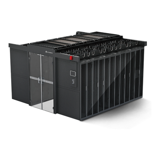
Huawei FusionModule5000 Series Installation Manual
Smart modular data center single-row aisle containment with 2000 mm high cabinets, ecc800
Hide thumbs
Also See for FusionModule5000 Series:
- Maintenance manual (198 pages) ,
- Commissioning manual (137 pages) ,
- Product description (123 pages)

Related Manuals for Huawei FusionModule5000 Series


Summary of Contents for Huawei FusionModule5000 Series
- Page 1 FusionModule5000 Smart Modular Data Center V100R001 Installation Guide (Single-Row Aisle Containment with 2000 mm High Cabinets, ECC800) Issue Date 2019-03-05 HUAWEI TECHNOLOGIES CO., LTD.
- Page 2 Notice The purchased products, services and features are stipulated by the contract made between Huawei and the customer. All or part of the products, services and features described in this document may not be within the purchase scope or the usage scope. Unless otherwise specified in the contract, all statements, information, and recommendations in this document are provided "AS IS"...
-
Page 3: About This Document
NOTICE is used to address practices not related to personal injury. Calls attention to important information, best practices and tips. NOTE is used to address information not related to personal injury, equipment damage, and environment Issue 01 (2019-03-05) Huawei Proprietary and Confidential Copyright © Huawei Technologies Co., Ltd. - Page 4 Changes between document issues are cumulative. The latest document issue contains all updates made in previous issues. Issue 01 (2019-03-05) This issue is the first official release. Issue 01 (2019-03-05) Huawei Proprietary and Confidential Copyright © Huawei Technologies Co., Ltd.
-
Page 5: Table Of Contents
4.1.2.3 Deploying the 600 mm Wide PDC Base ........................31 4.1.2.4 Deploying 800 mm Wide Fixed Bases ........................33 4.1.2.5 Securing Bases ................................34 4.2 Preparing for Installing Air Conditioners .......................... 36 4.2.1 Material Preparations............................... 36 Issue 01 (2019-03-05) Huawei Proprietary and Confidential Copyright © Huawei Technologies Co., Ltd. - Page 6 6.5 (Optional) Installing Aisle Lights ............................101 7 (Optional) Installing the New Main Way ............... 104 8 (Optional) Installing Cable Troughs ................105 8.1 Installing a 600 mm Wide Cable Trough.........................105 Issue 01 (2019-03-05) Huawei Proprietary and Confidential Copyright © Huawei Technologies Co., Ltd.
- Page 7 11 Installing Cabinet Sealing Plates ................... 167 12 Cable Routing ........................169 12.1 System Cabling Rules..............................169 12.2 Cable Routes for the Single-Row Aisle Containment Scenario (Power Supply and Distribution Cabinet) .....174 Issue 01 (2019-03-05) Huawei Proprietary and Confidential Copyright © Huawei Technologies Co., Ltd.
- Page 8 14.5 Commissioning the Management System (Power Supply and Distribution Cabinet) ..........197 14.6 Commissioning the Management System (New Main Way) ..................198 A Appendix ........................... 199 A.1 Contacting Huawei Technical Support (Carrier)......................199 A.2 Installing Expansion Sleeves............................199 A.3 Installing a Floating Nut ..............................200 A.4 Preparing a Monitoring Cable ............................201...
- Page 9 A.9 (Optional) Connecting the Linkage Cables Between the Fire Extinguishing System and Access Actuator ....234 B Common Screw Torques ....................235 C Installation Verification ....................237 D Acronyms and Abbreviation ................... 240 Issue 01 (2019-03-05) Huawei Proprietary and Confidential viii Copyright © Huawei Technologies Co., Ltd.
-
Page 10: Installation Preparations
Move the equipment close to the installation site before unpacking. Unpack the equipment with caution to avoid scratching or bumping. Take down the equipment from the pallet only immediately before installation. Figure 1-1 Transportation gradient Issue 01 (2019-03-05) Huawei Proprietary and Confidential Copyright © Huawei Technologies Co., Ltd. -
Page 11: Unpacking And Acceptance
Step 1 Unpack the carton labeled "Contain Packing List" and take out the Packing List. Step 2 Check all items against the Packing List. Step 3 If an item is incorrect or missing, contact Huawei technical support. Step 4 If any item is damaged, fill in the Cargo Replacement Application Form and report it. -
Page 12: Installation Environment Requirements
Inner dimensions: height > 2.4 m or depth > 2.7 m □ Compliant □ Cable tray Preinstalled in the equipment room for signal cables and power cables Incompliant Issue 01 (2019-03-05) Huawei Proprietary and Confidential Copyright © Huawei Technologies Co., Ltd. - Page 13 ECC collector, the camera, and the VCN respectively. NOTE An IP address is required for each camera. If any of the requirements is not met, contact Huawei technical support. Issue 01 (2019-03-05) Huawei Proprietary and Confidential Copyright © Huawei Technologies Co., Ltd.
-
Page 14: Site Requirements (Power Supply And Distribution Cabinet)
Open-skylight height L2: 550 mm When the base is configured, the equipment room net height equals the equipment room net height (without base) plus the base height. Issue 01 (2019-03-05) Huawei Proprietary and Confidential Copyright © Huawei Technologies Co., Ltd. -
Page 15: Site Requirements (New Main Way)
Table 1-2 Equipment Room Net Height Requirement (Without Base) Scenario Equipment room net height 2000 mm high cabinets and the new main > 2800 mm Issue 01 (2019-03-05) Huawei Proprietary and Confidential Copyright © Huawei Technologies Co., Ltd. - Page 16 First row new main way height L2: 455 Second row new main way height L3: 675 Smart module layout requirement Figure 1-6 shows the layout requirement for the smart module. Issue 01 (2019-03-05) Huawei Proprietary and Confidential Copyright © Huawei Technologies Co., Ltd.
-
Page 17: Documents
Download. integrated UPS. PDU8000 Modular Describes the installation, The document is delivered Precision PDC Quick Guide cable connection, and with the device, or you can Issue 01 (2019-03-05) Huawei Proprietary and Confidential Copyright © Huawei Technologies Co., Ltd. -
Page 18: Tools And Instruments
NetEco WebUI to software. obtain the NetEco version in use. Click Download. 1.7 Tools and Instruments This section lists the tools and instruments required for installation. Issue 01 (2019-03-05) Huawei Proprietary and Confidential Copyright © Huawei Technologies Co., Ltd. - Page 19 Hammer drill (Φ16 Electric screwdriver Heat gun Φ3.7, Φ4, Φ4.5, Φ5, drill bit) Φ6, Φ10, and Φ12 drill bits) Laser locator Electrician's knife Impact tool Polyvinyl chloride (PVC) insulation Issue 01 (2019-03-05) Huawei Proprietary and Confidential Copyright © Huawei Technologies Co., Ltd.
- Page 20 Claw hammer Vacuum cleaner Hacksaw Handsaw Right angle Heat shrink tubing Network cable tester Rubber mallet Adjustable socket screwdriver Flashlight Clamp meter Phase sequence Utility knife meter Issue 01 (2019-03-05) Huawei Proprietary and Confidential Copyright © Huawei Technologies Co., Ltd.
- Page 21 Open end torque wrench (2 PCS) M10/M12 wrench Steel brush Hot melt device Nitrogen cylinder Pressure gauge (used when the water pipes are made of PPR or aluminum-plastic material) Issue 01 (2019-03-05) Huawei Proprietary and Confidential Copyright © Huawei Technologies Co., Ltd.
-
Page 22: Tools Delivered With Equipment
The two types of marking-off templates are used respectively for cabinets that are 1100 mm and 1200 mm deep. For details about how to use a marking-off template, see Figure 1-9. Issue 01 (2019-03-05) Huawei Proprietary and Confidential Copyright © Huawei Technologies Co., Ltd. - Page 23 2000 mm High Cabinets, ECC800) 1 Installation Preparations Figure 1-7 Marking-off template for a 1100 mm deep cabinet Figure 1-8 Marking-off template for a 1200 mm deep cabinet Issue 01 (2019-03-05) Huawei Proprietary and Confidential Copyright © Huawei Technologies Co., Ltd.
-
Page 24: Personnel Requirements
Only trained and qualified personnel who fully understand basic safety precautions are allowed to install and operate a modular data center. Huawei will not be liable for any consequence caused by the violation of this document. The requirements are as follows: ... - Page 25 FusionModule5000 Smart Modular Data Center Installation Guide (Single-Row Aisle Containment with 2000 mm High Cabinets, ECC800) 1 Installation Preparations Figure 1-10 Installation process Issue 01 (2019-03-05) Huawei Proprietary and Confidential Copyright © Huawei Technologies Co., Ltd.
-
Page 26: Scenario Description (Power Supply And Distribution Cabinet)
To attach labels to the cabinets, name the single-row aisle containment row A, as shown in Figure 2-1. Issue 01 (2019-03-05) Huawei Proprietary and Confidential Copyright © Huawei Technologies Co., Ltd. - Page 27 (2) Flat or rotating skylight (3) Control skylight (4) Cable trough (5) Smart ETH gateway (6) Cabinet (7) For the alarm beacon (8) For the pad (9) For the access control Issue 01 (2019-03-05) Huawei Proprietary and Confidential Copyright © Huawei Technologies Co., Ltd.
-
Page 28: Scenario Description (New Main Way)
To attach labels to the cabinets, name the single-row aisle containment row A, as shown in Figure 3-1. Issue 01 (2019-03-05) Huawei Proprietary and Confidential Copyright © Huawei Technologies Co., Ltd. - Page 29 (4) Power distribution unit (5) Busbar trunking unit (6) Flat or rotating skylight (7) Cable trough (8) Cabinet (9) For the pad (10) For the access control (11) End door Issue 01 (2019-03-05) Huawei Proprietary and Confidential Copyright © Huawei Technologies Co., Ltd.
-
Page 30: Hardware Installation Preparations
For detailed dimensions requirements for bases, click Download. If you do not use the bases provided by Huawei, design the bearing requirements for bases according to the service plan. -
Page 31: Optional) Installing The Support For A Cabinet
Measure the distance (H) between the concrete floor and the upper surface of the ESD floor using a ruler and record the value of H, as shown in Figure 4-2. Issue 01 (2019-03-05) Huawei Proprietary and Confidential Copyright © Huawei Technologies Co., Ltd. - Page 32 Partially tighten the height-locking bolts on two sides, as shown by (2) in Figure 4-3. Figure 4-3 Partially tightening the height-locking bolts Step 2 Assemble the base, as shown in Figure 4-4. Issue 01 (2019-03-05) Huawei Proprietary and Confidential Copyright © Huawei Technologies Co., Ltd.
-
Page 33: Positioning Bases
Step 3 Use a marker to mark the outline of the cabinet on the floor and place one corner of the outline at the crossing point of the perpendicular lines. Issue 01 (2019-03-05) Huawei Proprietary and Confidential Copyright © Huawei Technologies Co., Ltd. - Page 34 Step 5 Use the end cabinet base as the reference and place other cabinet bases. Step 6 Partially install the front and rear pallets on the base, as shown by (1) in Figure 4-7. Issue 01 (2019-03-05) Huawei Proprietary and Confidential Copyright © Huawei Technologies Co., Ltd.
-
Page 35: Securing Bases
Step 8 Use a marker to mark the hole positions, as shown by (2) in Figure 4-7. ----End 4.1.1.3.3 Securing Bases Prerequisites The positions for installing bases have been determined. Issue 01 (2019-03-05) Huawei Proprietary and Confidential Copyright © Huawei Technologies Co., Ltd. - Page 36 Step 8 After securing bases, connect bases using connecting plates, as shown by (1) in Figure 4-11, and secure the screws to the floor holders on the bases, as shown by (2) in Figure 4-11. Issue 01 (2019-03-05) Huawei Proprietary and Confidential Copyright © Huawei Technologies Co., Ltd.
-
Page 37: Installing Fixed-Size Bases
A 300 mm wide fixed base adapts to a 300 mm wide air conditioner. The BOM number for a 300 mm wide fixed base is 21152146. Figure 4-12 shows a 300 mm wide fixed base. Issue 01 (2019-03-05) Huawei Proprietary and Confidential Copyright © Huawei Technologies Co., Ltd. - Page 38 Figure 4-13 Removing adjustable feet Move the adjustable feet to the mounting holes on the base according to the depth of the air conditioner. Issue 01 (2019-03-05) Huawei Proprietary and Confidential Copyright © Huawei Technologies Co., Ltd.
-
Page 39: Deploying Bases For A 600 Mm Wide It Cabinet/Battery Cabinet/Network Cabinet
600 mm wide fixed base. Deploy 600 mm wide fixed bases on the concrete floor according to the installation layout. When deploying the base, place the side marked FRONT facing upwards. Issue 01 (2019-03-05) Huawei Proprietary and Confidential Copyright © Huawei Technologies Co., Ltd. -
Page 40: Deploying The 600 Mm Wide Pdc Base
4.1.2.3 Deploying the 600 mm Wide PDC Base Context Figure 4-16 shows a 600 mm wide adjustable base. Figure 4-16 600 mm wide adjustable base (used for a PDC) Issue 01 (2019-03-05) Huawei Proprietary and Confidential Copyright © Huawei Technologies Co., Ltd. - Page 41 Step 2 Move the adjustable legs to the 1100 mm silkscreen at the FRONT end. Step 3 Secure the adjustable feet to the base using the four M6 screws removed in Step 1, as shown Figure 4-18. Issue 01 (2019-03-05) Huawei Proprietary and Confidential Copyright © Huawei Technologies Co., Ltd.
-
Page 42: Deploying 800 Mm Wide Fixed Bases
800 mm wide fixed base. Deploy 800 mm wide fixed bases on the concrete floor according to the installation layout. When deploying the base, place the side marked FRONT facing upwards. Issue 01 (2019-03-05) Huawei Proprietary and Confidential Copyright © Huawei Technologies Co., Ltd. -
Page 43: Securing Bases
The hole depth must range from 52 mm to 60 mm. Step 4 Use a vacuum cleaner to clean up dust in or around the holes, as shown in Figure 4-20. Issue 01 (2019-03-05) Huawei Proprietary and Confidential Copyright © Huawei Technologies Co., Ltd. - Page 44 Step 7 Move the base back to the position so that expansion bolts are inserted into mounting holes on supports. Secure the base to the concrete floor using expansion bolts obtained in Step 6.3, as shown in Figure 4-22. Issue 01 (2019-03-05) Huawei Proprietary and Confidential Copyright © Huawei Technologies Co., Ltd.
-
Page 45: Preparing For Installing Air Conditioners
Materials are classified to Huawei-provided, self-purchased, and onsite prepared materials, which are marked as mandatory, optional, and engineering purchasing in this document. Mandatory: materials that are provided by Huawei and can be obtained from delivered fittings Issue 01 (2019-03-05) Huawei Proprietary and Confidential Copyright ©... - Page 46 4 Hardware Installation Preparations Optional: materials that can be purchased from Huawei or by yourself. Engineering purchasing: materials that are not provided by Huawei and need to be prepared by the customer. Prepare the pipes and pipe fastenings listed in Table 4-2.
- Page 47 2.0 MPa or more, 20 filtration purchasing, based on pores, installed on the main chilled pipes reserved onsite water supply pipe Water Engineering pressure purchasing, based on Issue 01 (2019-03-05) Huawei Proprietary and Confidential Copyright © Huawei Technologies Co., Ltd.
- Page 48 1000 mm away from the changing point. The water inlet pipe can be connected for a humidifier in two ways, as shown in Figure 4-25. Issue 01 (2019-03-05) Huawei Proprietary and Confidential Copyright © Huawei Technologies Co., Ltd.
- Page 49 Select a stainless corrugated hose that is sealing gasket appropriate for the distance between the reserved port and steel pipe opening, and connect the pipe to the steel pipe and Issue 01 (2019-03-05) Huawei Proprietary and Confidential Copyright © Huawei Technologies Co., Ltd.
- Page 50 (8) Steel pipe (DN25, inch, BSPP, internal threaded recommended, to be connector, DN25 recommended, purchased) length 200 mm recommended, to be purchased) Table 4-4 describes the cables specifications. Issue 01 (2019-03-05) Huawei Proprietary and Confidential Copyright © Huawei Technologies Co., Ltd.
- Page 51 Bare crimp terminal, single cord- 2 PCS Standard end terminal, 1 mm , 5 A, tin configuratio plated, 6 mm insertion depth n; delivered with the product Issue 01 (2019-03-05) Huawei Proprietary and Confidential Copyright © Huawei Technologies Co., Ltd.
-
Page 52: Checking The Air Pressure
Step 2 Remove the air filters. Unfasten the eight rotating check plates in the upper and lower positions of the air filters, as shown in Figure 4-27. Issue 01 (2019-03-05) Huawei Proprietary and Confidential Copyright © Huawei Technologies Co., Ltd. - Page 53 If gas emits, the system is normal. Slowly open the exhaust valve to discharge nitrogen and close the valve when there is no airflow through the valve. If no gas emits out of the valve, contact Huawei technical support. Issue 01 (2019-03-05) Huawei Proprietary and Confidential...
-
Page 54: Installing Water Pipe Adapters
This section describes how to install a pagoda connector using method A. Procedure Step 1 Remove the side panels, as shown by Figure 4-29. Issue 01 (2019-03-05) Huawei Proprietary and Confidential Copyright © Huawei Technologies Co., Ltd. - Page 55 Apply thread sealant to the joints of external screw threads and install pagoda connectors from inside to outside, as shown by (6) in Figure 4-30. Issue 01 (2019-03-05) Huawei Proprietary and Confidential Copyright © Huawei Technologies Co., Ltd.
-
Page 56: Removing Transportation Fasteners For The Air Conditioner
4.2.4 Removing Transportation Fasteners for the Air Conditioner Context This step applies to the model with 1100 mm depth or 1200 mm depth, and electric heater or water pump. Issue 01 (2019-03-05) Huawei Proprietary and Confidential Copyright © Huawei Technologies Co., Ltd. -
Page 57: Removing Pallets
When moving a cabinet, verify that any open doors do not fall off. The cabinet with castors can be slid off its pallet using the PDC sliding panel. Issue 01 (2019-03-05) Huawei Proprietary and Confidential Copyright © Huawei Technologies Co., Ltd. -
Page 58: Removing The Pdc Pallet
If any damage is found, notify the carrier immediately. Check that the fittings comply with the packing list. If some fittings are missing or do not comply with the packing list, record the information and contact your local Huawei office immediately. - Page 59 Step 7 Raise the four leveling feet using an adjustable wrench, as shown in Figure 4-33. Figure 4-33 Raising the leveling feet Step 8 Move the PDC over its castors to the installation position. ----End Issue 01 (2019-03-05) Huawei Proprietary and Confidential Copyright © Huawei Technologies Co., Ltd.
-
Page 60: Removing The It Cabinet Pallet
If the cabinet needs to be secured, retain the screws you removed from the pallet for future use. Step 3 Remove the cabinet from the pallet. ----End Issue 01 (2019-03-05) Huawei Proprietary and Confidential Copyright © Huawei Technologies Co., Ltd. -
Page 61: Removing The Air Conditioner Pallet
If a pallet truck is unavailable or not allowed, transport the equipment by manpower. Six persons are required to complete the handling. Remove the side panel. Four Issue 01 (2019-03-05) Huawei Proprietary and Confidential Copyright © Huawei Technologies Co., Ltd. -
Page 62: Adjusting The Baffle Plate For The Air Conditioner
Perform the following procedure to change the position of the baffle plate if required. Procedure Step 1 Loosen the two screws shown by (1) in Figure 4-37. Issue 01 (2019-03-05) Huawei Proprietary and Confidential Copyright © Huawei Technologies Co., Ltd. -
Page 63: Optional) Adjusting It Cabinet Side Plates
Install two side plates for each end cabinet, one in the upper part and the other in the lower part. Issue 01 (2019-03-05) Huawei Proprietary and Confidential Copyright © Huawei Technologies Co., Ltd. -
Page 64: Optional) Adjusting Battery Cabinet Side Plates
After adjusting the side plate of the battery cabinet, remove the label which indicates side plate adjustment from the main battery cabinet. Issue 01 (2019-03-05) Huawei Proprietary and Confidential Copyright © Huawei Technologies Co., Ltd. -
Page 65: Optional) Installing The Pdc Tail Frame
Figure 4-39 Installed tail frame (1) Tail frame Procedure Step 1 Use eight M5 tapping screws to secure the tail frame accessories to the tail frame, as shown in Figure 4-40. Issue 01 (2019-03-05) Huawei Proprietary and Confidential Copyright © Huawei Technologies Co., Ltd. - Page 66 There are two upper sealing plates, and the one used in this step has a gap. Figure 4-41 shows the upper sealing plates of a tail frame. Figure 4-41 Upper sealing plates of a tail frame Issue 01 (2019-03-05) Huawei Proprietary and Confidential Copyright © Huawei Technologies Co., Ltd.
- Page 67 When removing the cabinet rear door, remove the ground cable between the cabinet and the rear door from the cabinet. Figure 4-43 Removing the cabinet rear door Issue 01 (2019-03-05) Huawei Proprietary and Confidential Copyright © Huawei Technologies Co., Ltd.
- Page 68 Step 6 Secure the tail frame to the PDC using eight M5 tapping screws, as shown in Figure 4-45. Issue 01 (2019-03-05) Huawei Proprietary and Confidential Copyright © Huawei Technologies Co., Ltd.
-
Page 69: Routing Air Conditioner Pipes
4.8 Routing Air Conditioner Pipes Preinstall the air conditioner pipes by referring to the onsite engineering layout diagram and NetCol5000-C 30 kW Chilled Water In-Row Precision Air Conditioner Quick Guide Issue 01 (2019-03-05) Huawei Proprietary and Confidential Copyright © Huawei Technologies Co., Ltd. - Page 70 Installation Guide (Single-Row Aisle Containment with 2000 mm High Cabinets, ECC800) 4 Hardware Installation Preparations (Simplified Edition). (The documents are delivered with the product. You can also download them by clicking Download.) Issue 01 (2019-03-05) Huawei Proprietary and Confidential Copyright © Huawei Technologies Co., Ltd.
-
Page 71: Installing The Cabinet
Figure 5-1. When leveling the cabinet, use a socket wrench, adjustable wrench, and flat-head screwdriver to adjust the anchor bolts. Issue 01 (2019-03-05) Huawei Proprietary and Confidential Copyright © Huawei Technologies Co., Ltd. - Page 72 Remove the M5x10 tapping screws that secure the connecting kits and then remove the connecting kits. Remove M4x10 screw assemblies from the position for combining cabinets. Secure the connecting kit using the M4x10 screw assemblies. Issue 01 (2019-03-05) Huawei Proprietary and Confidential Copyright © Huawei Technologies Co., Ltd.
- Page 73 Installation Guide (Single-Row Aisle Containment with 2000 mm High Cabinets, ECC800) 5 Installing the Cabinet Figure 5-2 Interconnecting cabinets Step 4 Secure the cabinet. Figure 5-3 Securing a cabinet Issue 01 (2019-03-05) Huawei Proprietary and Confidential Copyright © Huawei Technologies Co., Ltd.
-
Page 74: Positioning Cabinets (Without Bases)
Use a marker to mark the outline of the marking-off template and the mounting holes for the cabinet on the floor. Issue 01 (2019-03-05) Huawei Proprietary and Confidential Copyright © Huawei Technologies Co., Ltd. -
Page 75: Installing Cabinets (Without Bases)
2000 mm high cabinet. ----End 5.3 Installing Cabinets (Without Bases) Procedure Step 1 Place end cabinets in the marked positions, as shown in Figure 5-5. Issue 01 (2019-03-05) Huawei Proprietary and Confidential Copyright © Huawei Technologies Co., Ltd. - Page 76 Figure 5-6. When leveling the cabinet, use a socket wrench, adjustable wrench, and flat-head screwdriver to adjust the anchor bolts. Issue 01 (2019-03-05) Huawei Proprietary and Confidential Copyright © Huawei Technologies Co., Ltd.
- Page 77 Remove the M5x10 tapping screws that secure the connecting kits and then remove the connecting kits. Remove M4x10 screw assemblies from the position for combining cabinets. Secure the connecting kit using the M4x10 screw assemblies. Issue 01 (2019-03-05) Huawei Proprietary and Confidential Copyright © Huawei Technologies Co., Ltd.
- Page 78 5 Installing the Cabinet Figure 5-7 Interconnecting cabinets Step 4 Install other cabinets in a similar way. Step 5 (Optional) Secure the cabinets, as shown in Figure 5-8. Issue 01 (2019-03-05) Huawei Proprietary and Confidential Copyright © Huawei Technologies Co., Ltd.
-
Page 79: Installing Cabinet Accessories
Step 1 Remove the rodent-proof mesh on the top of the PDU2000 in a cabinet, and take out the two PDU2000 industrial connectors from the top, as shown in Figure 5-9. Issue 01 (2019-03-05) Huawei Proprietary and Confidential Copyright © Huawei Technologies Co., Ltd. - Page 80 Figure 5-10 Laying out PDU2000 industrial connectors and cables Repeat the preceding steps to take out and preinstall PDU2000 industrial connectors for all cabinets. ----End Issue 01 (2019-03-05) Huawei Proprietary and Confidential Copyright © Huawei Technologies Co., Ltd.
-
Page 81: Optional) Installing Branch Ground Copper Bars
(outside), and secure the ground bar using the M8 screws removed earlier, as shown in Figure 5-12. Install the branch ground copper bar in the battery cabinet or IT cabinet adjacent to the PDC. Issue 01 (2019-03-05) Huawei Proprietary and Confidential Copyright © Huawei Technologies Co., Ltd. -
Page 82: Optional) Installing The Vertical Ground Bar
M4 screws respectively at the 04 U, 14 U, 29 U, and 39 U positions. Note that a screw should be secured to the middle tapped hole of each U. Issue 01 (2019-03-05) Huawei Proprietary and Confidential Copyright © Huawei Technologies Co., Ltd. -
Page 83: Optional) Setting A Mechanical Coded Lock
Unlocking with a Key Step 1 Insert the cabinet key into the lock hole and turn it for 180 degrees counterclockwise to unlock, as shown in Figure 5-14. Issue 01 (2019-03-05) Huawei Proprietary and Confidential Copyright © Huawei Technologies Co., Ltd. - Page 84 Step 1 Enter the password and turn the knob for 180 degrees counterclockwise to unlock, as shown Figure 5-15. The preset password is 0, 0, 0. Figure 5-15 Unlocking with a password Issue 01 (2019-03-05) Huawei Proprietary and Confidential Copyright © Huawei Technologies Co., Ltd.
- Page 85 Figure 5-16. Figure 5-16 Changing the password Step 3 Turn the knob for 15 degrees clockwise to finish password changing. ----End Issue 01 (2019-03-05) Huawei Proprietary and Confidential Copyright © Huawei Technologies Co., Ltd.
-
Page 86: Installing The Contained Aisles
When determining the position, verify that adjacent sealing plates will be in close contact with each other. The distance between the cabinet front frame and the outer sealing plate is 1290 mm. Issue 01 (2019-03-05) Huawei Proprietary and Confidential Copyright © Huawei Technologies Co., Ltd. - Page 87 Step 4 Secure the sealing plates to the floor using ST4.8x25 tapping screws or DKBA44091028 plastic expansion bolts and gaskets, as shown by (2) in Figure 6-1. Issue 01 (2019-03-05) Huawei Proprietary and Confidential Copyright © Huawei Technologies Co., Ltd.
-
Page 88: Installing Skylights
The 600 mm wide control skylight is used to install monitoring components such as the camera, multi-functional sensor, or smoke detector. It is used with 600 mm wide cabinets at the end of the smart module. Issue 01 (2019-03-05) Huawei Proprietary and Confidential Copyright © Huawei Technologies Co., Ltd. -
Page 89: Mm Wide Control Skylight
Figure 6-4 shows a 600 mm wide flat skylight. Figure 6-5 shows a 600 mm wide rotating skylight. Issue 01 (2019-03-05) Huawei Proprietary and Confidential Copyright © Huawei Technologies Co., Ltd. -
Page 90: Mm Wide Flat Or Rotating Skylight
Figure 6-6 shows an 800 mm wide flat skylight. Figure 6-7 shows an 800 mm wide rotating skylight. Issue 01 (2019-03-05) Huawei Proprietary and Confidential Copyright © Huawei Technologies Co., Ltd. -
Page 91: Mm Wide Flat Skylight
(2) Skylight connective plate (3) Rotating skylight panel 6.2.1.5 300 mm Wide Flat Skylight Figure 6-8 shows a 300 mm wide flat skylight. Its BOM number is 21501040. Issue 01 (2019-03-05) Huawei Proprietary and Confidential Copyright © Huawei Technologies Co., Ltd. -
Page 92: Securing Skylights
Use four M8x20 screws to partially secure the two skylight connective plates to the correct mounting holes, as shown by (1) in Figure 6-9. Issue 01 (2019-03-05) Huawei Proprietary and Confidential Copyright © Huawei Technologies Co., Ltd. - Page 93 Step 4 Keep the end planes of adjacent skylight connective plates flush with each other and connect the adjacent skylight connective plates using two M6x16 screws with flat washers and nuts. Issue 01 (2019-03-05) Huawei Proprietary and Confidential Copyright © Huawei Technologies Co., Ltd.
-
Page 94: Installing A Rotating Skylight Magnetic Lock
Step 1 Remove the four M4x12 screws (set aside) from the magnetic lock base and take off the lock base from the rotating skylight, as shown by (1) in Figure 6-11. Issue 01 (2019-03-05) Huawei Proprietary and Confidential Copyright © Huawei Technologies Co., Ltd. -
Page 95: Installing End Doors
The cabinets and enclosure plates at both ends of an smart module □ Incompliant are placed with a front-backward deviation no greater than 1.5 □ Compliant The height deviation between the floor surface and support top is Issue 01 (2019-03-05) Huawei Proprietary and Confidential Copyright © Huawei Technologies Co., Ltd. -
Page 96: Installing A Cabinet Lower Mounting Kit
600 mm wide cabinets. (3) in Figure 6-13 shows the assembled front and rear sealing plates for 800 mm wide cabinets. Issue 01 (2019-03-05) Huawei Proprietary and Confidential Copyright © Huawei Technologies Co., Ltd. - Page 97 Step 3 Place the side sealing plate with the side with dents upward, and snap the side sealing plate into the front and rear sealing plates, as shown by (2) in Figure 6-14. ----End Issue 01 (2019-03-05) Huawei Proprietary and Confidential Copyright © Huawei Technologies Co., Ltd.
-
Page 98: Installing A Revolving Door
The door posts on both sides require four screws, as shown by (2) in Figure 6-16. Verify that the posts are flush with the cabinet frame. Issue 01 (2019-03-05) Huawei Proprietary and Confidential Copyright © Huawei Technologies Co., Ltd. - Page 99 600.5 mm (± 2 mm) wide. Stand the door panels and remove the four rubber strips from the two door panels, as shown in Figure 6-17. Issue 01 (2019-03-05) Huawei Proprietary and Confidential Copyright © Huawei Technologies Co., Ltd.
- Page 100 Secure the hinges on the upper part and then those on the lower part. This facilitates hinge adjustment. After fixing the door hinges, install the rubber covers onto the screws, as shown in Figure 6-18. Issue 01 (2019-03-05) Huawei Proprietary and Confidential Copyright © Huawei Technologies Co., Ltd.
- Page 101 Figure 6-18 Installing door panels Secure each hinge on the side of the door post using two M4 screw assemblies, as shown Figure 6-19. Figure 6-19 Installing door panels Issue 01 (2019-03-05) Huawei Proprietary and Confidential Copyright © Huawei Technologies Co., Ltd.
- Page 102 If the door slightly tilts, add a pad under the corresponding post to correct the tilt. Both methods must ensure that there is no gap between the post bottom and the floor. Issue 01 (2019-03-05) Huawei Proprietary and Confidential Copyright © Huawei Technologies Co., Ltd.
- Page 103 Pull the lower end of the post outwards if a corner of a door panel tilts upwards. Figure 6-21 Door panel tilting down Issue 01 (2019-03-05) Huawei Proprietary and Confidential Copyright © Huawei Technologies Co., Ltd.
- Page 104 After confirming that the door box is level, partially secure the door box to the cabinet, as shown by (2) in Figure 6-22. Figure 6-22 Installing the door box hanging kit Issue 01 (2019-03-05) Huawei Proprietary and Confidential Copyright © Huawei Technologies Co., Ltd.
- Page 105 Table 6-3 Door box placement faults Fault Type Possible Cause Measure Door box tilted with a V- The top front and rear of the For details about the Issue 01 (2019-03-05) Huawei Proprietary and Confidential Copyright © Huawei Technologies Co., Ltd.
- Page 106 V-shaped gap disappears, as shown by (1) in Figure 6-26. Figure 6-25 V-shaped gap Figure 6-26 Adjusting the V-shaped gap Issue 01 (2019-03-05) Huawei Proprietary and Confidential Copyright © Huawei Technologies Co., Ltd.
- Page 107 (1) in Figure 6-28. Figure 6-27 Λ-shaped gap Figure 6-28 Adjusting the Λ-shaped gap Step 8 Adjust the positions of the door box fasteners. Issue 01 (2019-03-05) Huawei Proprietary and Confidential Copyright © Huawei Technologies Co., Ltd.
-
Page 108: Attaching Cabinet Labels
6.4 Attaching Cabinet Labels Prerequisites Skylights and end doors are secured. Context Cabinet labels are useful for subsequent cable connections. Procedure Step 1 Take out cabinet labels from package 0. Issue 01 (2019-03-05) Huawei Proprietary and Confidential Copyright © Huawei Technologies Co., Ltd. - Page 109 If there is no dented imprint on the skylight connective plate, attach a label at the accurate position shown in Figure 6-30. Figure 6-30 Position for attaching a label Ensure that labels are properly aligned. ----End Issue 01 (2019-03-05) Huawei Proprietary and Confidential Copyright © Huawei Technologies Co., Ltd.
-
Page 110: Optional) Installing Aisle Lights
A light tube has male and female connectors at both ends for interconnection, as shown in Figure 6-32. When installing lights, ensure that all the male connectors face the same direction (also the female connectors) for serial connection of light tubes. Issue 01 (2019-03-05) Huawei Proprietary and Confidential Copyright © Huawei Technologies Co., Ltd. - Page 111 Ensure that each light tube is secured by three holders. Figure 6-33 Installing a light tube Step 2 Install a light tube onto the holders, as shown by (2) in Figure 6-33. Issue 01 (2019-03-05) Huawei Proprietary and Confidential Copyright © Huawei Technologies Co., Ltd.
- Page 112 Installation Guide (Single-Row Aisle Containment with 2000 mm High Cabinets, ECC800) 6 Installing the Contained Aisles Step 3 Install other light tubes in the same way. ----End Issue 01 (2019-03-05) Huawei Proprietary and Confidential Copyright © Huawei Technologies Co., Ltd.
-
Page 113: Optional) Installing The New Main Way
2000 mm High Cabinets, ECC800) 7 (Optional) Installing the New Main Way (Optional) Installing the New Main Way Install the new main way by referring to the documents delivered with it. Issue 01 (2019-03-05) Huawei Proprietary and Confidential Copyright © Huawei Technologies Co., Ltd. -
Page 114: Optional) Installing Cable Troughs
PDU2000 cables and industrial connectors in the cable trough above the rear door. After PDU2000 cables and industrial connectors are placed, bind the cables to the cable trough using cable ties. Issue 01 (2019-03-05) Huawei Proprietary and Confidential Copyright © Huawei Technologies Co., Ltd. - Page 115 Figure 8-3 Clamping a vertical plate Step 2 Rotate the vertical plate by 90 degrees to stand it on the top plate of the cabinet, as shown in Figure 8-4. Issue 01 (2019-03-05) Huawei Proprietary and Confidential Copyright © Huawei Technologies Co., Ltd.
- Page 116 Figure 8-6. Ensure that the supporting plate is fully into the clasps. When installing the supporting plate, do not remove the grommet strip on the U-shaped trough. Issue 01 (2019-03-05) Huawei Proprietary and Confidential Copyright © Huawei Technologies Co., Ltd.
- Page 117 Step 7 Rotate the interconnecting wrench and clamp it into the clasps until the wrench is horizontal, as shown in Figure 8-8. This operation interconnects the cable troughs. Issue 01 (2019-03-05) Huawei Proprietary and Confidential Copyright © Huawei Technologies Co., Ltd.
-
Page 118: Installing A 300 Mm Wide Cable Trough
A 300 mm wide cable trough is installed on the top of a 300 mm wide cabinet after a 600 mm wide cable trough is installed. Figure 8-9 shows a 300 mm wide cable trough. Its BOM number is 21501141. Issue 01 (2019-03-05) Huawei Proprietary and Confidential Copyright © Huawei Technologies Co., Ltd. - Page 119 Figure 8-10 Connecting a 300 mm wide cable trough to a 600 mm wide cable trough (1) Interconnecting wrench ----End Issue 01 (2019-03-05) Huawei Proprietary and Confidential Copyright © Huawei Technologies Co., Ltd.
-
Page 120: Installing An 800 Mm Wide Cable Trough
The installation method is similar to the method for installing a 600 mm wide cable trough. For details, see 8.1 Installing a 600 mm Wide Cable Trough. Issue 01 (2019-03-05) Huawei Proprietary and Confidential Copyright © Huawei Technologies Co., Ltd. -
Page 121: Installing Monitoring Devices
9-2. When there is a special grounding requirement and a cabinet ground bar can be deployed, use the ground cable prepared by the customer to connect from the device ground point to the cabinet ground bar. Issue 01 (2019-03-05) Huawei Proprietary and Confidential Copyright © Huawei Technologies Co., Ltd. -
Page 122: Optional) Installing A Server
The following installation procedure uses an RH2288 V2 server as an example. For more information, see the documents delivered with the server. Procedure Step 1 Install guide rails, as shown in Figure 9-3. Issue 01 (2019-03-05) Huawei Proprietary and Confidential Copyright © Huawei Technologies Co., Ltd. - Page 123 Step 3 Align the two mounting ears of the server with the rack rail of the cabinet and tighten the screws on the mounting ears. Figure 9-4 Installing the server Issue 01 (2019-03-05) Huawei Proprietary and Confidential Copyright © Huawei Technologies Co., Ltd.
-
Page 124: Optional) Installing A Vcn500
Step 2 Place the VCN500 into the network cabinet with caution, and gently press down buttons on the mounting ears, as shown in Figure 9-6. Issue 01 (2019-03-05) Huawei Proprietary and Confidential Copyright © Huawei Technologies Co., Ltd. -
Page 125: Optional) Installing A Lan Switch
9.4 (Optional) Installing a LAN Switch Procedure Step 1 Determine the mounting holes for the LAN switch based on the network cabinet device layout, adjust the guide rails, and install floating nuts. Issue 01 (2019-03-05) Huawei Proprietary and Confidential Copyright © Huawei Technologies Co., Ltd. - Page 126 Insert the power modules into the power slots of the 24-port LAN switch, and tighten the captive screws on the power module panel, as shown in Figure 9-9. Figure 9-9 Installing the power modules for a 24-port LAN switch Issue 01 (2019-03-05) Huawei Proprietary and Confidential Copyright © Huawei Technologies Co., Ltd.
-
Page 127: Installing An Ecc800
Figure 9-11 Removing an ECC800 main control module Install the SIM card in the correct slot on the left side of the ECC800 main control module, as shown in Figure 9-12. Issue 01 (2019-03-05) Huawei Proprietary and Confidential Copyright © Huawei Technologies Co., Ltd. - Page 128 Connect the 2.4G antenna cable to the RF_Z antenna port on the ECC800. (Optional) Connect the 3G antenna cable to the 3G/4G antenna port on the ECC800, as shown in Figure 9-14. Issue 01 (2019-03-05) Huawei Proprietary and Confidential Copyright © Huawei Technologies Co., Ltd.
-
Page 129: Optional) Installing A Rack Environment Unit
Step 6 Connect the ECC800 power cable to the PDU2000. ----End 9.6 (Optional) Installing a Rack Environment Unit Context Install a rack environment unit on the rack rail of the cabinet rear door. Issue 01 (2019-03-05) Huawei Proprietary and Confidential Copyright © Huawei Technologies Co., Ltd. -
Page 130: Installing Monitoring Components On A Control Skylight
----End 9.7 Installing Monitoring Components on a Control Skylight Monitoring components should be installed in the appropriate holes on the control skylight, as shown in Figure 9-17. Issue 01 (2019-03-05) Huawei Proprietary and Confidential Copyright © Huawei Technologies Co., Ltd. -
Page 131: Installing A Camera
Use the wrench delivered with the camera to loosen the screws on the front cover of the camera, remove the front cover, and take out the inner cover clipped on the lens, as shown in Figure 9-18. Issue 01 (2019-03-05) Huawei Proprietary and Confidential Copyright © Huawei Technologies Co., Ltd. - Page 132 Step 2 Align the holes in the camera base with those in the control skylight, and secure the camera to the control skylight using three M3 screws, as shown in Figure 9-20. Issue 01 (2019-03-05) Huawei Proprietary and Confidential Copyright © Huawei Technologies Co., Ltd.
- Page 133 Step 3 Before installing the inner cover, adjust the infrared light panel of the camera to keep the photoresistor perpendicular to the camera base, so that the infrared light and photoresistor will not be blocked. See Figure 9-22. Issue 01 (2019-03-05) Huawei Proprietary and Confidential Copyright © Huawei Technologies Co., Ltd.
- Page 134 Step 4 Install the front cover of the camera in the direction shown in Figure 9-23, and tighten the screws on the front cover. Remove the protective film from the transparent cover. Figure 9-23 Installing the front cover ----End Issue 01 (2019-03-05) Huawei Proprietary and Confidential Copyright © Huawei Technologies Co., Ltd.
-
Page 135: Optional) Installing A Smoke Detector
Step 2 Route the cables of the multi-functional sensor through the cable holes in the control skylight, as shown by (2) in Figure 9-25. Step 3 Secure the multi-functional sensor to the mounting base, as shown by (3) in Figure 9-25. Issue 01 (2019-03-05) Huawei Proprietary and Confidential Copyright © Huawei Technologies Co., Ltd. -
Page 136: Optional) Installing Monitoring Components On The End Door
9.8 (Optional) Installing Monitoring Components on the End Door 9.8.1 Monitoring Component Layout for the Revolving Door Figure 9-26 shows the installation positions for monitoring components on the revolving door. Issue 01 (2019-03-05) Huawei Proprietary and Confidential Copyright © Huawei Technologies Co., Ltd. -
Page 137: Installing An Actuator Or Converter
BOM numbers, see Table 9-1. The monitoring components mentioned in this section can be installed in the same way. The WiFi converter is used as an example. Issue 01 (2019-03-05) Huawei Proprietary and Confidential Copyright © Huawei Technologies Co., Ltd. - Page 138 Figure 9-28. Shake the WiFi converter in different directions to check that it is securely installed. Issue 01 (2019-03-05) Huawei Proprietary and Confidential Copyright © Huawei Technologies Co., Ltd.
- Page 139 (facing the aisle). Then connect the WiFi antennas to the RF_1 and RF_2 ports on the WiFi converter, as shown in Figure 9-30. Issue 01 (2019-03-05) Huawei Proprietary and Confidential Copyright © Huawei Technologies Co., Ltd.
-
Page 140: Installing An Alarm Beacon
Figure 9-31 Installing a rear panel 9.8.3 Installing an Alarm Beacon Context The BOM number of an alarm beacon is 22010028. By default, one micro-module is equipped with one alarm beacon only. Issue 01 (2019-03-05) Huawei Proprietary and Confidential Copyright © Huawei Technologies Co., Ltd. -
Page 141: Optional) Installing A Revolving Door Magnetic Lock
If no magnetic lock is configured, the cover is used to cover up the magnetic lock installation position. If a magnetic lock is configured, remove the cover and install the magnetic lock. Issue 01 (2019-03-05) Huawei Proprietary and Confidential Copyright © Huawei Technologies Co., Ltd. - Page 142 Step 2 Remove the magnetic lock fixing plate. Remove the fixing plate from the revolving door magnetic lock using the hex key delivered with the magnetic lock. Four hex socket screws need to be removed in this step. Issue 01 (2019-03-05) Huawei Proprietary and Confidential Copyright © Huawei Technologies Co., Ltd.
- Page 143 (2) in Figure 9-35. Figure 9-35 Installing a magnetic lock Step 5 Install the mounting plate of the magnetic lock cover, as shown in Figure 9-36. Issue 01 (2019-03-05) Huawei Proprietary and Confidential Copyright © Huawei Technologies Co., Ltd.
- Page 144 When securing the magnetic to the door panel, do not over-tighten the screws so that the white rubber washer is elastic. The washer will adjust the magnetic to a correct position because of its elasticity. Issue 01 (2019-03-05) Huawei Proprietary and Confidential Copyright © Huawei Technologies Co., Ltd.
- Page 145 (1) in Figure 9-39. If the magnet is not level, use a spacer shown by (2) in Figure 9-39 to adjust the magnet levelness. Issue 01 (2019-03-05) Huawei Proprietary and Confidential Copyright © Huawei Technologies Co., Ltd.
-
Page 146: Installing Buttons
Step 3 Secure the button to the post using the nut delivered with the button, as shown by (3) in Figure 9-40. Figure 9-40 Installing a button Issue 01 (2019-03-05) Huawei Proprietary and Confidential Copyright © Huawei Technologies Co., Ltd. -
Page 147: Installing The Pad Mounting Kit
Baffle plate with the cable Used for installing the card reader with a hole in the middle keypad or the IC card reader. Issue 01 (2019-03-05) Huawei Proprietary and Confidential Copyright © Huawei Technologies Co., Ltd. -
Page 148: Installing A Fingerprint And Card Reader
Step 1 Remove the M4 nuts, spring washers, and flat washers (set aside) from the baffle plate in the target installation position and remove the baffle plate, as shown by (1) in Figure 9-42. Issue 01 (2019-03-05) Huawei Proprietary and Confidential Copyright © Huawei Technologies Co., Ltd. -
Page 149: Installing A Fingerprint And Card Reader With A Keypad
Step 1 Remove the M4 nuts, spring washers, and flat washers (set aside) from the baffle plate in the target installation position and remove the baffle plate, as shown by (1) in Figure 9-43. Issue 01 (2019-03-05) Huawei Proprietary and Confidential Copyright © Huawei Technologies Co., Ltd. -
Page 150: Installing A Card Reader With A Keypad
Step 1 Remove the M4 nuts, spring washers, and flat washers (set aside) from the baffle plate in the target installation position and remove the baffle plate, as shown by (1) in Figure 9-44. Issue 01 (2019-03-05) Huawei Proprietary and Confidential Copyright © Huawei Technologies Co., Ltd. -
Page 151: Installing An Ic Card Reader
Step 1 Remove the M4 nuts, spring washers, and flat washers (set aside) from the baffle plate in the target installation position and remove the baffle plate, as shown by (1) in Figure 9-45. Issue 01 (2019-03-05) Huawei Proprietary and Confidential Copyright © Huawei Technologies Co., Ltd. - Page 152 After the IC card reader has been installed properly, reinstall the cover on the card reader immediately. Otherwise, the card reader will trigger an alarm after it is powered on. ----End Issue 01 (2019-03-05) Huawei Proprietary and Confidential Copyright © Huawei Technologies Co., Ltd.
-
Page 153: Installing A Pad Power Connector
Clamp the power connector to the guide rail of the holder. Install the holder cover using two M4x12 screw assemblies. Install the holder baffle plate using one M4x12 screw assembly. Issue 01 (2019-03-05) Huawei Proprietary and Confidential Copyright © Huawei Technologies Co., Ltd. - Page 154 Figure 9-47 Assembling a pad power connector holder (BOM number: 14190242) Step 2 Connect cables from the power connector to the AC actuator, and route the cables, as shown in the following figure. Issue 01 (2019-03-05) Huawei Proprietary and Confidential Copyright © Huawei Technologies Co., Ltd.
- Page 155 Remove the baffle plate from the power connector mounting holes in the door box. Secure the pad power connector holder to the door box using two M4x12 screw assemblies. Figure 9-50 Securing the pad power connector holder (1) Door box Issue 01 (2019-03-05) Huawei Proprietary and Confidential Copyright © Huawei Technologies Co., Ltd.
-
Page 156: Installing A Pad
Step 5 Adjust the foot in the upper part of the pad mounting bracket and clamp the pad into the mounting bracket, as shown by (4) in Figure 9-52. Issue 01 (2019-03-05) Huawei Proprietary and Confidential Copyright © Huawei Technologies Co., Ltd. -
Page 157: Securing The Pad Mounting Kit
Step 2 Clamp the pad mounting kit to the hanging kit, as shown by (2) in Figure 9-53. Step 3 Secure the pad mounting kit to the hanging kit using two M5x10 tapping screws, as shown by (3) in Figure 9-53. Issue 01 (2019-03-05) Huawei Proprietary and Confidential Copyright © Huawei Technologies Co., Ltd. - Page 158 Skip this step if no pad is installed. Route the access monitoring cable from the cable hole in the door box baffle plate, as shown in Figure 9-55. Issue 01 (2019-03-05) Huawei Proprietary and Confidential Copyright © Huawei Technologies Co., Ltd.
- Page 159 Figure 9-55 Routing the access monitoring cable (no pad is configured) Step 5 Tighten two M3 captive screws to secure the baffle plate to the hanging kit, as shown in Figure 9-56. Issue 01 (2019-03-05) Huawei Proprietary and Confidential Copyright © Huawei Technologies Co., Ltd.
-
Page 160: Optional) Installing A Smart Eth Gateway
A total Module length ≤ 7 m; number of air of 4 PCS should be deployed, as shown in conditioners ≤ 4 Figure 9-57. Issue 01 (2019-03-05) Huawei Proprietary and Confidential Copyright © Huawei Technologies Co., Ltd. - Page 161 Rack environment unit deployed Deploy 2 PCS for each end cabinet and 1 PCS for every three cabinets among other cabinets in the smart module, as shown in Figure 9-59. Issue 01 (2019-03-05) Huawei Proprietary and Confidential Copyright © Huawei Technologies Co., Ltd.
- Page 162 Press the lower part of the smart ETH gateway to clamp the ETH gateway onto the guide rail. Shake the smart ETH gateway in different directions to ensure that it is reliably installed. Issue 01 (2019-03-05) Huawei Proprietary and Confidential Copyright © Huawei Technologies Co., Ltd.
-
Page 163: Installing Temperature Sensors
Procedure Step 1 Bind temperature sensors to the cabinet frames of corresponding cabinets using cable ties, as shown in Figure 9-61. Issue 01 (2019-03-05) Huawei Proprietary and Confidential Copyright © Huawei Technologies Co., Ltd. -
Page 164: Rules For Deploying T/H Sensors
Determine the number of T/H sensors to be deployed based on the number of air conditioners. Each air conditioner can be configured with three more external T/H sensors. Issue 01 (2019-03-05) Huawei Proprietary and Confidential Copyright © Huawei Technologies Co., Ltd. - Page 165 Assign the third T/H sensor to the cabinet that is between the first T/H sensor and the air conditioner and near the air conditioner, as shown by (3) in Figure 9-64 Figure 9-65. Issue 01 (2019-03-05) Huawei Proprietary and Confidential Copyright © Huawei Technologies Co., Ltd.
-
Page 166: Installing A T/H Sensor
Hot-aisle control by air conditioner: The air conditioner controls the temperature at rear doors of IT cabinets so that the temperature is close to the temperature set on the air conditioner. Issue 01 (2019-03-05) Huawei Proprietary and Confidential Copyright © Huawei Technologies Co., Ltd. - Page 167 Step 1 Use two M5x10 tapping screws to secure the T/H sensor base to the IT cabinet door frame 1.8 m above the ground. Step 2 Mount the T/H sensor onto the base. Figure 9-66 Installing a T/H sensor ----End Issue 01 (2019-03-05) Huawei Proprietary and Confidential Copyright © Huawei Technologies Co., Ltd.
-
Page 168: Installing A Wlds900 Water Sensor (Used In Intelligent Micro-Modular)
Figure 9-67 Water sensor components (1) Water detector (2) Conversion cable end A, (3) Conversion connected to the water detector cable Issue 01 (2019-03-05) Huawei Proprietary and Confidential Copyright © Huawei Technologies Co., Ltd. - Page 169 Step 2 Connect the other end of the conversion cable to the water detector, as shown in Figure 9-69. Figure 9-69 Connecting the water detector ----End Issue 01 (2019-03-05) Huawei Proprietary and Confidential Copyright © Huawei Technologies Co., Ltd.
-
Page 170: Laying Out The Water Detection Cable (Top Pipe Routing)
Step 1 Plan the installation position for the fastener of the water detection cable. Ensure that the water detection cable placed on the fastener is in good contact with the floor. One fastener is provided for a 1 meter long water detection cable. Issue 01 (2019-03-05) Huawei Proprietary and Confidential Copyright © Huawei Technologies Co., Ltd. - Page 171 If multiple water detection cables need to be connected in series, connect the male connector of one cable to the female connector of another. Figure 9-73 Securing a water detection cable ----End Issue 01 (2019-03-05) Huawei Proprietary and Confidential Copyright © Huawei Technologies Co., Ltd.
-
Page 172: Laying Out The Water Detection Cable (Bottom Pipe Routing)
(4) Water detection cable Do not contact the water detection cable to metal, for this action will cause a false alarm. Take protective measures when routing a water detection cable. Issue 01 (2019-03-05) Huawei Proprietary and Confidential Copyright © Huawei Technologies Co., Ltd. - Page 173 Figure 9-77. If multiple water detection cables need to be connected in series, connect the male connector of one cable to the female connector of another. Issue 01 (2019-03-05) Huawei Proprietary and Confidential Copyright © Huawei Technologies Co., Ltd.
- Page 174 FusionModule5000 Smart Modular Data Center Installation Guide (Single-Row Aisle Containment with 2000 mm High Cabinets, ECC800) 9 Installing Monitoring Devices Figure 9-77 Securing a water detection cable ----End Issue 01 (2019-03-05) Huawei Proprietary and Confidential Copyright © Huawei Technologies Co., Ltd.
-
Page 175: Optional) Installing In-Room Cable Trays
2000 mm High Cabinets, ECC800) 10 (Optional) Installing In-Room Cable Trays (Optional) Installing In-Room Cable Trays Install the in-room cable trays by referring to Indoor Cable Tray Installation Guide. Issue 01 (2019-03-05) Huawei Proprietary and Confidential Copyright © Huawei Technologies Co., Ltd. -
Page 176: Installing Cabinet Sealing Plates
Step 1 Install a sealing plate for the cabinet front door and secure it using two M5x10 tapping screws, as shown in Figure 11-1. Keep the edgefold of the sealing plate facing the cabinet. Issue 01 (2019-03-05) Huawei Proprietary and Confidential Copyright © Huawei Technologies Co., Ltd. - Page 177 Figure 11-2 Installing 300 mm Wide Air Conditioner Sealing Plates Step 2 Install another sealing plate on the other side of the cabinet in the same way. ----End Issue 01 (2019-03-05) Huawei Proprietary and Confidential Copyright © Huawei Technologies Co., Ltd.
-
Page 178: Cable Routing
To route and bind cables in an appealing way, follow these rules: Neatly organize exterior cables in a large bundle of cables and prevent cable tangles that are avoidable, as shown in Figure 12-1. Issue 01 (2019-03-05) Huawei Proprietary and Confidential Copyright © Huawei Technologies Co., Ltd. - Page 179 12-3. Also comply with these rules when cables of different thickness are bound together. Arrange cables by thickness when arrangement by thickness conflicts with arrangement by color. Issue 01 (2019-03-05) Huawei Proprietary and Confidential Copyright © Huawei Technologies Co., Ltd.
- Page 180 Provide slack at cable connection positions to facilitate connection and disconnection and to prevent stress. Do not leave the cables tight and prevent connector misalignment, as shown in Figure 12-4. Figure 12-4 Cable connection positions Issue 01 (2019-03-05) Huawei Proprietary and Confidential Copyright © Huawei Technologies Co., Ltd.
- Page 181 Bind cables by a moderate force and ensure that cables are not misshapen to prevent compromising the signal quality. After binding cables, cut off the excess parts of cable ties and trim away any burrs, as shown in Figure 12-6. Issue 01 (2019-03-05) Huawei Proprietary and Confidential Copyright © Huawei Technologies Co., Ltd.
- Page 182 Figure 12-7 Binding cables in a bending area Ensure that the cable ties are wrapped and secured in the same direction and do not generate interference with subsequent operations, as shown in Figure 12-8. Issue 01 (2019-03-05) Huawei Proprietary and Confidential Copyright © Huawei Technologies Co., Ltd.
-
Page 183: Cable Routes For The Single-Row Aisle Containment Scenario (Power Supply And Distribution Cabinet)
Ensure that strong-current cables and weak-current cables are at least 100 mm away from each other. Issue 01 (2019-03-05) Huawei Proprietary and Confidential Copyright © Huawei Technologies Co., Ltd. -
Page 184: Cable Routes For The Single-Row Aisle Containment Scenario (New Main Way)
12.3 Cable Routes for the Single-Row Aisle Containment Scenario (New Main Way) Figure 12-10 shows how cables are routed in the single-row aisle containment scenario when you are configuring the new main way. Issue 01 (2019-03-05) Huawei Proprietary and Confidential Copyright © Huawei Technologies Co., Ltd. - Page 185 Figure 12-10 Routing power cables and signal cables (1) General input unit (2) Power distribution unit (3) Conversion unit (4) Signal cable (5) Network cabinet (6) Power cable Issue 01 (2019-03-05) Huawei Proprietary and Confidential Copyright © Huawei Technologies Co., Ltd.
-
Page 186: Cable Routing For Cabinet Door Monitoring Components
(A) To the COM1/12V or COM2/12V port on the rack environment unit Figure 12-12 Cabling routing for a door status sensor (A) To the AI/DI1 or AI/DI2 port on the rack environment unit Issue 01 (2019-03-05) Huawei Proprietary and Confidential Copyright © Huawei Technologies Co., Ltd. -
Page 187: Cable Routing For The Network Cabinet
The cables must be routed out of the cable holes in the left and right posts. Issue 01 (2019-03-05) Huawei Proprietary and Confidential Copyright © Huawei Technologies Co., Ltd. -
Page 188: Cable Routes For The Aisle Lighting System
(8) Actuator or button button magnetic lock converter 12.7 Cable Routes for the Aisle Lighting System Figure 12-15 shows the cable routes for the aisle lighting system. Issue 01 (2019-03-05) Huawei Proprietary and Confidential Copyright © Huawei Technologies Co., Ltd. - Page 189 For lights in different groups, power must be supplied to each group separately. Figure 12-16 Cable connections to lights in the same group (1) AC actuator (2) Light Issue 01 (2019-03-05) Huawei Proprietary and Confidential Copyright © Huawei Technologies Co., Ltd.
-
Page 190: Installing An Sms Modem
An idle serial port is available on the server. Context Bind an SMS modem (BOM number: 50030084) to the rack rail at the rear of the network cabinet near the server using cable ties. Issue 01 (2019-03-05) Huawei Proprietary and Confidential Copyright © Huawei Technologies Co., Ltd. - Page 191 After connecting the power cable, switch on the power supply. The modem indicator should blink regularly. Table 12-2 describes the relationships between the indicator status and the modem status. Issue 01 (2019-03-05) Huawei Proprietary and Confidential Copyright © Huawei Technologies Co., Ltd.
-
Page 192: Connecting The Ground Cables For The Smart Module
12.9.1 Grounding Cabinets M-type Grounding Cabinets are grounded by cables connected from the main ground copper bars shown by (2) in Figure 12-20 to the nearby ground grid. Issue 01 (2019-03-05) Huawei Proprietary and Confidential Copyright © Huawei Technologies Co., Ltd. - Page 193 PDC. If no branch ground bar is installed, connect the cabinet ground copper bar or ground point directly to the general ground bar inside the PDC. Issue 01 (2019-03-05) Huawei Proprietary and Confidential Copyright © Huawei Technologies Co., Ltd.
-
Page 194: Optional) Connecting Base Ground Cables
Figure 12-21 S-type grounding 12.9.2 (Optional) Connecting Base Ground Cables Figure 12-22 shows the base ground points. Select either of the following base grounding solution depending on the actual situation. Issue 01 (2019-03-05) Huawei Proprietary and Confidential Copyright © Huawei Technologies Co., Ltd. - Page 195 Figure 12-23. Then connect the module ground cables by following instructions in 12.9.1 Grounding Cabinets. Figure 12-23 Connecting the ground cable between the base and cabinet Issue 01 (2019-03-05) Huawei Proprietary and Confidential Copyright © Huawei Technologies Co., Ltd.
-
Page 196: Cable Installation For The Power Supply And Distribution System
Figure 12-25. Figure 12-24 Installing a separator Issue 01 (2019-03-05) Huawei Proprietary and Confidential Copyright © Huawei Technologies Co., Ltd. - Page 197 Correct Method for Connecting Battery Cables When the length of a battery cable equals the distance between two battery terminals, connect the cable straight through, as shown in Figure 12-27. Issue 01 (2019-03-05) Huawei Proprietary and Confidential Copyright © Huawei Technologies Co., Ltd.
- Page 198 Figure 12-28. To prevent misshaping battery terminals, do not connect the cable in the way shown in Figure 12-29. Figure 12-28 Correct battery cable connection method Issue 01 (2019-03-05) Huawei Proprietary and Confidential Copyright © Huawei Technologies Co., Ltd.
- Page 199 (Optional) If two battery strings are deployed, connect the UPS terminals +, N, and - for one battery string to the UPS terminals +, N, and - for the other battery string. Issue 01 (2019-03-05) Huawei Proprietary and Confidential Copyright © Huawei Technologies Co., Ltd.
- Page 200 (Optional) If the intelligent battery monitoring system is deployed, for details about how to install, connect cables, and power on the BIM and CIM, see iBAT 2.0-CIM01C2 User Manual (Click Download.). Issue 01 (2019-03-05) Huawei Proprietary and Confidential Copyright © Huawei Technologies Co., Ltd.
-
Page 201: Connecting Cables To Power Supply And Distribution Devices
The document is delivered with the device, or you can click Download. Precision PDC PDU8000 Modular Precision PDC Quick Guide (1100 mm Deep) The document is delivered with the device, or you can click Download. Issue 01 (2019-03-05) Huawei Proprietary and Confidential Copyright © Huawei Technologies Co., Ltd. -
Page 202: Connecting Cables For The Cooling System
Download. 12.12 Connecting Cables for the Management System See Smart Module Management System Wiring Diagram (The document is delivered with the device, or you can click Download). Issue 01 (2019-03-05) Huawei Proprietary and Confidential Copyright © Huawei Technologies Co., Ltd. -
Page 203: Installation Verification
FusionModule5000 Smart Modular Data Center Installation Guide (Single-Row Aisle Containment with 2000 mm High Cabinets, ECC800) 13 Installation Verification Installation Verification C Installation Verification lists the items to be checked. Issue 01 (2019-03-05) Huawei Proprietary and Confidential Copyright © Huawei Technologies Co., Ltd. -
Page 204: Power-On Commissioning
Table 14-1 lists the reference documents. Table 14-1 Device Reference Integrated UPS UPS5000-E-(40 kVA–128 kVA) Quick Guide (Integrated UPS 2.0) The document is delivered with the device, Issue 01 (2019-03-05) Huawei Proprietary and Confidential Copyright © Huawei Technologies Co., Ltd. -
Page 205: Commissioning The Power Supply And Distribution System (New Main Way)
NetCol5000-C 30 kW Chilled Water In-Row Precision Air Chilled Water In-Row Conditioner Quick Guide (Simplified Edition) Precision Air The document is delivered with the device, or you can click Conditioner Download. Issue 01 (2019-03-05) Huawei Proprietary and Confidential Copyright © Huawei Technologies Co., Ltd. -
Page 206: Commissioning The Management System (Power Supply And Distribution Cabinet)
Smart ETH gateway Access actuator Cabinet electronic lock Door status sensor Access control Camera WiFi converter Skylight actuator AC actuator Alarm beacon Water sensor Multi-functional sensor Smoke detector Issue 01 (2019-03-05) Huawei Proprietary and Confidential Copyright © Huawei Technologies Co., Ltd. -
Page 207: Commissioning The Management System (New Main Way)
Access actuator Cabinet electronic lock Door status sensor Access control device Camera WiFi converter Skylight actuator AC actuator Audible and Visual Alarm Water Sensor Multi-functional sensor Smoke detector Issue 01 (2019-03-05) Huawei Proprietary and Confidential Copyright © Huawei Technologies Co., Ltd. -
Page 208: A Appendix
2000 mm High Cabinets, ECC800) A Appendix Appendix A.1 Contacting Huawei Technical Support (Carrier) When contacting Huawei technical support, you need to provide the following information: Full name of the site Name and phone number of the contact person ... -
Page 209: Installing A Floating Nut
Figure A-2 Drilling a hole and installing an expansion sleeve (unit: mm) ----End A.3 Installing a Floating Nut Figure A-3 shows how to install a floating nut. Issue 01 (2019-03-05) Huawei Proprietary and Confidential Copyright © Huawei Technologies Co., Ltd. -
Page 210: Preparing A Monitoring Cable
Strip the insulation layer of cable B to expose cable core C. Put cable core C through cord end terminal A. Crimp the metal part of cord end terminal A using the crimping tool. Issue 01 (2019-03-05) Huawei Proprietary and Confidential Copyright © Huawei Technologies Co., Ltd. - Page 211 (A) Cord end terminal connector (B) Insulation layer (C) Copper core wire Preparing an RS485 Monitoring Cable Figure A-5 shows how to prepare a monitoring cable for the ECC collector. Issue 01 (2019-03-05) Huawei Proprietary and Confidential Copyright © Huawei Technologies Co., Ltd.
-
Page 212: Scenario With A Column (600 Mm Wide It Cabinets Scenario)
A.5 Scenario with a Column (600 mm Wide IT Cabinets Scenario) A.5.1 Scenario Description This section describes the column position in the scenario with a column relative to the adjustable skylight, sealing plates, and cable trays. Issue 01 (2019-03-05) Huawei Proprietary and Confidential Copyright © Huawei Technologies Co., Ltd. - Page 213 (4) Flat or rotating (5) Adjustable (6) Two connected sealing plates with the skylight skylight concave sides facing rightwards (7) Column in the equipment room Issue 01 (2019-03-05) Huawei Proprietary and Confidential Copyright © Huawei Technologies Co., Ltd.
- Page 214 Install an adjustable skylight over the aisle containment. The area to be covered by the adjustable skylight is shown in Figure A-7. Issue 01 (2019-03-05) Huawei Proprietary and Confidential Copyright © Huawei Technologies Co., Ltd.
- Page 215 Install an adjustable skylight over the aisle containment. The area to be covered by the adjustable skylight is shown in Figure A-8. Issue 01 (2019-03-05) Huawei Proprietary and Confidential Copyright © Huawei Technologies Co., Ltd.
- Page 216 Install an adjustable skylight over the aisle containment. The area to be covered by the adjustable skylight is shown in Figure A-9. Issue 01 (2019-03-05) Huawei Proprietary and Confidential Copyright © Huawei Technologies Co., Ltd.
- Page 217 Install an adjustable skylight over the aisle containment. The area to be covered by the adjustable skylight is shown in Figure A-10. Issue 01 (2019-03-05) Huawei Proprietary and Confidential Copyright © Huawei Technologies Co., Ltd.
- Page 218 Install flat or rotating skylights over the aisle containment. If sealing plates cannot be installed on both sides of the column, install sealing plates only near the aisle containment. Issue 01 (2019-03-05) Huawei Proprietary and Confidential Copyright © Huawei Technologies Co., Ltd.
-
Page 219: Installation Process For Scenarios With Columns
The cabinet bottom sealing plate installed in the scenario with a column is the same as the mounting kit installed under the end cabinet. The BOM number is 21242007. Issue 01 (2019-03-05) Huawei Proprietary and Confidential Copyright © Huawei Technologies Co., Ltd. -
Page 220: Installing Sealing Plates Near The Aisle
Table A-2 Sealing plate types Sealing Plate BOM Number 300 mm wide, 2000 mm high sealing plate 21500707 Issue 01 (2019-03-05) Huawei Proprietary and Confidential Copyright © Huawei Technologies Co., Ltd. - Page 221 DKBA44091028 and four washers. If drilling holes in the ESD floor is not supported onsite, use four ST4.8x25 self-drilling tapping screws and washers for securing. Issue 01 (2019-03-05) Huawei Proprietary and Confidential Copyright © Huawei Technologies Co., Ltd.
-
Page 222: Installing The Adjustable Skylight
Figure A-15 Components of an adjustable skylight (1) Skylight connective plates (2) Polycarbonate (PC) plate fasteners (3) L-shaped mounting bracket (4) PC plate clip (5) PC plate supports (6) PC plate Issue 01 (2019-03-05) Huawei Proprietary and Confidential Copyright © Huawei Technologies Co., Ltd. -
Page 223: Installing The Skylight Connective Plate
(1) Column ----End A.5.5.2 Installing the Telescopic Edges Procedure Step 1 Extend the two telescopic edges to an appropriate length and secure them using two M6 screws. Issue 01 (2019-03-05) Huawei Proprietary and Confidential Copyright © Huawei Technologies Co., Ltd. - Page 224 Figure A-17 Adjusting the length of a telescopic edge Step 2 Secure the two telescopic edges to the skylight connective plate using four M6 screws. Figure A-18 Installing telescopic edges (1) Column ----End Issue 01 (2019-03-05) Huawei Proprietary and Confidential Copyright © Huawei Technologies Co., Ltd.
-
Page 225: Installing An Adjustable Skylight Side Sealing Plate
Figure A-20 Installation position of the adjustable skylight side sealing plate (1) Adjustable skylight side sealing plate Issue 01 (2019-03-05) Huawei Proprietary and Confidential Copyright © Huawei Technologies Co., Ltd. - Page 226 Figure A-22 Attaching a PC plate fastener to a trimmed PC plate Step 3 Secure the PC plate fastener and the trimmed PC plate to the skylight connective plate. Issue 01 (2019-03-05) Huawei Proprietary and Confidential Copyright © Huawei Technologies Co., Ltd.
-
Page 227: Installing The Pc Plate Support And Pc Plate
If the space between the right side of the column and the right side of the adjustable skylight is less than 600 mm, PC plate support 2 does not need to be installed. Issue 01 (2019-03-05) Huawei Proprietary and Confidential Copyright © Huawei Technologies Co., Ltd. - Page 228 Step 2 Secure the two PC plate supports to the telescopic edges of the adjustable skylight using four M6 screws and nuts. Figure A-25 Installing PC plate supports (1) Column Step 3 Install L-shaped mounting brackets. Issue 01 (2019-03-05) Huawei Proprietary and Confidential Copyright © Huawei Technologies Co., Ltd.
- Page 229 Figure A-26 Securing L-shaped mounting brackets (1) Column Step 4 Install PC plates. Pave PC plates on the adjustable skylight. Secure PC plate fasteners to PC plate supports. Issue 01 (2019-03-05) Huawei Proprietary and Confidential Copyright © Huawei Technologies Co., Ltd.
-
Page 230: Installing Cable Trays
Determine the position and mode (combined or layered) for installing cable trays based on the actual installation environment and the description in A.5.1 Scenario Description. Context Cable trays can be installed in two modes: Combined installation Issue 01 (2019-03-05) Huawei Proprietary and Confidential Copyright © Huawei Technologies Co., Ltd. - Page 231 FusionModule5000 Smart Modular Data Center Installation Guide (Single-Row Aisle Containment with 2000 mm High Cabinets, ECC800) A Appendix Figure A-28 Combined installation Layered installation Issue 01 (2019-03-05) Huawei Proprietary and Confidential Copyright © Huawei Technologies Co., Ltd.
- Page 232 Step 1 Assemble cable trays. Place four cable tray supports at the coated positions on the cable trays. Secure each support to the cable trays using four M8 screws. Figure A-30 Assembling cable trays Issue 01 (2019-03-05) Huawei Proprietary and Confidential Copyright © Huawei Technologies Co., Ltd.
-
Page 233: Installing A Sealing Plates Away The Aisle
Stand outside the smart module during the installation. Procedure Step 1 Secure the two sealing plates using three M6 screws and nuts. Issue 01 (2019-03-05) Huawei Proprietary and Confidential Copyright © Huawei Technologies Co., Ltd. -
Page 234: Optional) Connecting Cables To Industrial Connectors
Connectors Figure A-33 Figure A-34 show only the cable connection methods. The industrial connector cable connections depend on the industrial connector type and wiring port silk screen. Issue 01 (2019-03-05) Huawei Proprietary and Confidential Copyright © Huawei Technologies Co., Ltd. -
Page 235: Optional) Connecting Pdu2000 Cables
PDU2000 cables. Figure A-35–Figure A-37 show only the cable connection methods. PDU2000 cable connections depend on the PDU2000 type and wiring port silk screen. Issue 01 (2019-03-05) Huawei Proprietary and Confidential Copyright © Huawei Technologies Co., Ltd. - Page 236 Installation Guide (Single-Row Aisle Containment with 2000 mm High Cabinets, ECC800) A Appendix Figure A-35 Connecting PDU2000 cables (method 1) Figure A-36 Connecting PDU2000 cables (method 2) Issue 01 (2019-03-05) Huawei Proprietary and Confidential Copyright © Huawei Technologies Co., Ltd.
- Page 237 2000 mm High Cabinets, ECC800) A Appendix Figure A-37 Connecting PDU2000 cables (method 3) Step 2 (Optional) Route cables for the half-sized PDU2000, as shown in Figure A-38. Issue 01 (2019-03-05) Huawei Proprietary and Confidential Copyright © Huawei Technologies Co., Ltd.
- Page 238 PDU2000 cables through the openings, as shown by (1), (2), and (3) in Figure A-39. Figure A-39 Taking out PDU2000 cables Issue 01 (2019-03-05) Huawei Proprietary and Confidential Copyright © Huawei Technologies Co., Ltd.
-
Page 239: Cable Routes Inside An It Cabinet
Figure A-40 Cable route along a horizontal cable manager (1) Small cable ring (2) Cable manager (3) Customer equipment Issue 01 (2019-03-05) Huawei Proprietary and Confidential Copyright © Huawei Technologies Co., Ltd. - Page 240 (1) Cable tray (2) Big cable ring (3) Customer equipment The cable tray is optional and used to lead cables from the cabinet front to the cabinet rear. Issue 01 (2019-03-05) Huawei Proprietary and Confidential Copyright © Huawei Technologies Co., Ltd.
- Page 241 The depth-directed cable tray is optional and used to manage the cable routes on the side of a cabinet. Figure A-43 Figure A-44 show the routes of the cables out from the rear of customer equipment. Issue 01 (2019-03-05) Huawei Proprietary and Confidential Copyright © Huawei Technologies Co., Ltd.
- Page 242 FusionModule5000 Smart Modular Data Center Installation Guide (Single-Row Aisle Containment with 2000 mm High Cabinets, ECC800) A Appendix Figure A-43 Power cable route Figure A-44 Signal cable route Issue 01 (2019-03-05) Huawei Proprietary and Confidential Copyright © Huawei Technologies Co., Ltd.
-
Page 243: Optional) Connecting The Linkage Cables Between The Fire Extinguishing System And Access Actuator
AI/DI_1 port. Figure A-45 Connecting fire alarm signal cables to the access actuator Issue 01 (2019-03-05) Huawei Proprietary and Confidential Copyright © Huawei Technologies Co., Ltd. -
Page 244: B Common Screw Torques
Cross recessed pan head combination, or outdoor thread forming screw M5 cable clip (GB/T 6560-1986) M8/M8 expansion bolt (tension/implosion) Issue 01 (2019-03-05) Huawei Proprietary and Confidential Copyright © Huawei Technologies Co., Ltd. - Page 245 M6 screw assembly M8 screw assembly M10 screw assembly M12 screw assembly M16 screw assembly Cord end terminal block 2.2–2.5 M2.5 5–6 6–8 M3.5 8–16 15–18 25–30 32–37 Issue 01 (2019-03-05) Huawei Proprietary and Confidential Copyright © Huawei Technologies Co., Ltd.
-
Page 246: C Installation Verification
The cabinet filler panels are in proper positions so that the cold aisle and hot aisle are isolated. Incompliant Aisle Containment Checklist Check Item Check Result □ Compliant □ All aisle containment components are installed. Issue 01 (2019-03-05) Huawei Proprietary and Confidential Copyright © Huawei Technologies Co., Ltd. - Page 247 Cables are bound neatly, and cable ties are secured evenly and properly in the same direction. □ Compliant □ Incompliant Cables are routed in a way convenient for Issue 01 (2019-03-05) Huawei Proprietary and Confidential Copyright © Huawei Technologies Co., Ltd.
- Page 248 Battery cables are correctly connected, and the terminal voltages of battery strings are normal. □ Compliant □ Incompliant DIP switches on devices are correctly set. Customer signature: Check date: Issue 01 (2019-03-05) Huawei Proprietary and Confidential Copyright © Huawei Technologies Co., Ltd.
-
Page 249: D Acronyms And Abbreviation
Battery Interface Module BSPP British Standard Pipe Parallel Thread BSPT British Standard Taper Pipe Thread Communication Interface Module Direct Current Energy Control Center EPDM Ethylene-Propylene-Diene tripolymer Expandable Polyethylene Ethernet Issue 01 (2019-03-05) Huawei Proprietary and Confidential Copyright © Huawei Technologies Co., Ltd. - Page 250 Power Distribution Unit Protective Earthing Power over Ethernet PP-R Polypropylene Random Polyvinyl Chloride Secure Digital Subscriber Identity Module Uninterruptible Power System Video Cloud Node WiFi Wireless Fidelity Issue 01 (2019-03-05) Huawei Proprietary and Confidential Copyright © Huawei Technologies Co., Ltd.
Need help?
Do you have a question about the FusionModule5000 Series and is the answer not in the manual?
Questions and answers