
Related Manuals for Vacon optea


Summary of Contents for Vacon optea
- Page 1 ® ac drives advanced dual port ethernet board, optea dual port ethernet board, opte9 installation manual...
-
Page 3: Table Of Contents
VACON® 100 X ..................42 PC Tools ...........................45 5.8.1 PC tool support ........................45 5.8.2 Updating the OPTEA and OPTE9 option board firmware with VACON® Loader ....46 5.8.3 PC Tools for VACON® NX / NCIPConfig ................49 5.8.4 PC Tools for VACON® NX / NCDrive ................51 5.8.5 PC Tools for VACON®... - Page 4 • 4 6.1.8 EIP Input and Output instance ..................64 6.1.9 EIP Product code offset ....................64 6.1.10 Mode ..........................64 6.1.11 MAC Address........................65 6.1.12 Modbus Unit Identifier .....................65 6.1.13 Media Redundancy ......................66 6.1.14 SNTP settings........................66 6.1.15 SNTP monitoring values ....................68 6.1.16 System Redundancy......................68 Internal communication modes..................68...
- Page 5 11.2 Control Word bit support in VACON® AC drives ............207 11.3 Vacon® Status Word - FBFixedStatusWord..............208 11.4 Status Word bit support in VACON® AC drives.............209 11.5 Monitoring of Control & Status words in VACON® AC drives........209 11.6 VACON® Speed reference and actual speed - FBSpeedReference and FBActualSpeed ......................210 11.7 Process data........................210...
-
Page 6: Safety
• 6 Safety AFETY This manual contains clearly marked cautions and warnings that are intended for your personal safety and to avoid any unintentional damage to the product or connected appliances. Read the information included in cautions and warnings carefully. -
Page 7: Warnings
(EN 13006.emf 60204-1). ® Only spare parts delivered by VACON can be used. 13006.emf At power-up, power break or fault reset the motor will start immediately if the start signal is active, unless the pulse control for Start/Stop logic has been selected. -
Page 8: Grounding And Earth Fault Protection
• 8 Safety Grounding and earth fault protection CAUTION! 13006.emf The AC drive must always be earthed with an grounding conductor connected to the grounding terminal marked with The earth leakage current of the drive exceeds 3.5mA AC. According to EN61800-5-1, one or more... -
Page 9: General Information
The Advanced Dual Port Ethernet board (OPTEA) also supports PROFINET IO with PROFIsafe in combination with OPTBL/OPTBM/OPTBN option board. In addition, OPTEA also supports advanced features such as PROFINET System Redundancy "S2". OPTEA can be used alone as PROFINET IO device, but PROFIsafe always requires OPTBL/OPTBM/OPTBN option board and ®... - Page 10 • 10 General information Table 2. List of abbreviations used in this document Abbreviation Explanation RSTP Rapid Spanning Tree Protocol SNTP Simple Network Time Protocol Transmission Control Layer provides reliable, ordered and error-checked delivery of data streams between computers that are connected to a local area network.
-
Page 11: New Features - Optea
General information vacon • 11 New features - OPTEA The following table shows the new features that are added in the OPTEA Advanced Dual Port Ethernet's firmware version. Table 4. New features - OPTEA New feature Firmware version PROFINET IO + PROFIsafe... -
Page 12: Optea/Opte9 Ethernet Board Technical Data
• 12 OPTEA/OPTE9 Ethernet board technical OPTEA/OPTE9 E THERNET BOARD TECHNICAL DATA General Table 6. Technical data General Board name OPTEA/OPTE9 Interface Two RJ-45 connectors Ethernet connections Transfer cable Shielded Twisted Pair (STP) CAT5e Speed 10 / 100 Mb... -
Page 13: Layout And Connections
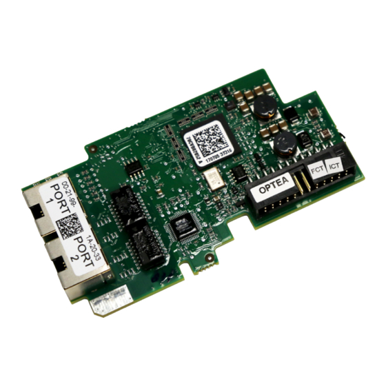
Ethernet option boards are connected to the Ethernet bus using the standard RJ45 connectors (1 and 2). The communication between the control board and the AC drive takes place ® through a standard VACON Interface Board Connector. OPTEA and OPTE9 boards have identical layout and connections. Layout and connections RN ER BS... -
Page 14: Led Indications
• 14 Layout and connections LED Indications RN ER BS 11593_00 LED indications Figure 2. Option board LED indicators The table below lists possible LED combinations and their meanings. When the EtherNet/IP is active, the option board follows CIP standard for LED indications. Therefore, the indications described in Table 8 do not apply. -
Page 15: Profinet Io
Layout and connections vacon • 15 LED combinations Description Protocol is communicating. Protocol communication fault. ER is blinking to indicate a fault. RN is blinking to indicate that protocol is again ready for communications. Protocol is communicating with an active fault. ER is blinking. -
Page 16: Ethernet Devices
® ® NOTE! The Ethernet connection to VACON 20, VACON 20 X and VACON 20 CP via the OPTE9 Dual Port Ethernet is not supported. OPTEA Advanced Dual Port Ethernet board does not support ® ® ® VACON 20, VACON 20 X or VACON 20 CP. -
Page 17: Machine To Machine
Layout and connections vacon • 17 4.3.2 Machine to machine Requirements: - Industrial environment - Fast communication in use MASTER Real-Time Control - Start/Stop, Direction,... - Reference - Feedback Ethernet switch Power 11595_uk Figure 4. Ethernet, Machine to Machine Connections and wiring The option boards have two Ethernet ports and an embedded switch. -
Page 18: Topology: Star
• 18 Layout and connections 4.4.1 Topology: Star In star network, all the devices are connected to the same switch(es). This topology reduces the damage caused by single cable failure. It would affect only to a single drive instead of them all. In this setup, a drive will receive only broadcast/multicast messages and messages directed to this drive. -
Page 19: Topology: Ring
Layout and connections vacon • 19 4.4.3 Topology: Ring In some cases it is possible to use a ring topology. The ring topology gains the same reduced cabling cost as the daisy chain topology, but decreases the damage caused by a single cable failure. - Page 20 • 20 Layout and connections Managed switch with RSTP support Power DRIVE DRIVE DRIVE DRIVE OPTE9-1 OPTE9-2 OPTE9-3 OPTE9-8 11661_uk Figure 7. Ring topology In the example below, the Ethernet communication will be interrupted to device number three and other devices after that when the link is broken.
- Page 21 Layout and connections vacon • 21 Configuration example The screenshots below (Figure 9, Figure 10) show one example of configuring the RSTP in the switch (in this case an EtherWAN switch). Port two is the designated port and port one is the alternative port.
- Page 22 PLC or network switch. The other nodes in the network are called Media Redundancy Clients (MRC), and they react on received configuration frames from the MRM and can detect link changes on its ring ports. OPTEA and OPTE9 boards support only MRC functionality.
- Page 23 Typically, in PROFINET IO systems the recovery time is defined as 200 ms. However, the MRP specification allows for recovery times of 500, 200, 30 and 10 ms. OPTEA and OPTE9 boards can be used in systems with the lowest recovery time of 10 ms. This is often called “Fast MRP”.
- Page 24 • 24 Layout and connections • Only the following packets are processed from the blocked port: • Beacon frames from self and other supervisors • Link_Status/Neighbor_Status frames • Neighbor_Check request or response and Sign_On frames RING SUPERVISOR Beacon Beacon...
-
Page 25: Acd (Address Conflict Detection)
ACD (Address Conflict Detection) The OPTEA and OPTE9 option boards implement ACD algorithm (IETF RFC 5227). The implementation includes requirements from the EtherNet/IP protocol. The ACD algorithm tries to actively detect if the IP address configured to this device is been used by another device in the same network. -
Page 26: Time Synchronization
NXP/NXS AC drives can be updated by writing 32 ® bit unsigned value to ID 2551. This value is seconds since 1.1.1970 (Unix time). In VACON family, the default timezone is UTC. Local time can be configured by changing the timezone and ®... -
Page 27: Installation
VACON AC drives. Option board can be used for PROFINET IO with PROFIsafe communication in slot E, when OPTBL/OPTBM/OPTBN is installed to slot D. If PROFIsafe is not used, then OPTEA can be installed to slot D too. Table 10. OPTEA supported AC drives and slots... -
Page 28: Vacon® Opte9 Dual Port Ethernet Drive Support
VACON OPTE9 Dual Port Ethernet drive support ® ® The VACON OPTE9 Dual Port Ethernet option board can be used with the following VACON drives. Table 12. OPTE9 supported AC drives and slots From AC drive SW From OPTE9 SW... -
Page 29: Installation In Vacon® Nx
Installation vacon • 29 ® Installation in VACON Make sure that the AC drive is switched off before an option or fieldbus board is changed or added! 13006.emf ® VACON NX AC drive. Remove the cable cover. Open the cover of the control unit. - Page 30 • 30 Installation Install the option board in slot D or E on the control board of the AC drive. Make sure that the grounding plate fits tightly in the clamp. Make a sufficiently wide opening for your cable by cutting the grid as wide as necessary.
-
Page 31: Installation In Vacon® 20
Installation vacon • 31 Installation in VACON® 20 5.4.1 Enclosures MI1, MI2, MI3 Remove the cable connector lid from the AC drive. 11555A_00 Select a correct grounding plate and attach it to the option board mounting enclosure. The grounding plate is marked with the supported enclosure size. - Page 32 • 32 Installation Connect the flat cable from the option board mounting enclosure to V20. 11557A_00 If a cable strain relief is required, attach the parts as shown in the figure. 11558A_00 Local contacts: https://www.danfoss.com/en/contact-us/contacts-list/...
- Page 33 Installation vacon • 33 Install the option board to the option board holder. Make sure that the option board is securely fastened. 11559A_00 Cut free a sufficiently wide opening for the option board connector. 11650_00 Attach the option board cover to V20. Attach the strain relief cable clamp with screws if needed.
-
Page 34: Enclosures Mi4, Mi5
• 34 Installation 5.4.2 Enclosures MI4, MI5 Make sure power is disconnected before opening the V20 cover. 13006.emf 1a: For MI4: Open the cover. 11561_00 1b: For MI5: Open the cover and release the fan connector. 11562_00 Connect the flex cable to option board connector PCB. - Page 35 Installation vacon • 35 Connect the option board to connector PCB. 11565_00 Attach the option board with connector PCB to V20 and connect the flex cable. 11566_00 Attach a suitable grounding plate to V20. The grounding plate is marked with supported enclosure size.
- Page 36 • 36 Installation Assemble a clamp on top of the grounding plate on both sides of the option board. 11568_00 8a: For MI4: Close the cover. 11569_00 8b: For MI5: Remount the fan connector and close the cover. 11570_00...
-
Page 37: Installation In Vacon® 20 X And 20 Cp
Installation vacon • 37 ® Installation in VACON 20 X and 20 CP Do not add or replace option boards or fieldbus boards on an AC drive with the power switched on. This may damage the boards. 13006.emf Open the cover of the drive. - Page 38 • 38 Installation Remove the option slot cover. 7089_00 Install the option board into the slot as shown in the figure. 7090_00 Mount the option slot cover. Remove the plastic opening for the option board terminals. 7091_00 7091_00 Local contacts: https://www.danfoss.com/en/contact-us/contacts-list/...
-
Page 39: Installation In Vacon® 100 Family
100 family Open the cover of the AC drive. M4x55 9174.emf The relay outputs and other I/O-terminals may have a dangerous control voltage ® present even when VACON 100 family AC drive is disconnected from mains. DANGER Local contacts: https://www.danfoss.com/en/contact-us/contacts-list/... - Page 40 Open the inner cover to reveal the option board slots (C,D,E). 3023.emf Install the fieldbus board into slot D or E. ® NOTE: Incompatible boards cannot be installed on VACON 100 family AC drive. Compatible boards have a slot coding that enable the placing of the board. 3024.emf Then connect the cable to its appropriate RJ-45 connector.
- Page 41 Installation vacon • 41 Unless already done for the other control cables, cut free the opening on the AC drive cover for the fieldbus cable (protection class IP21). NOTE: Cut the opening on the same side you have installed the board in! Remount the AC drive cover and run the cable as shown in picture.
-
Page 42: Installation In Vacon® 100 X
• 42 Installation ® installation in VACON 100 X Open the cover of the AC drive. 11638_00 Local contacts: https://www.danfoss.com/en/contact-us/contacts-list/... - Page 43 Installation vacon • 43 To get access to the option board slots, remove the screws and open the cover of the control unit. 11639_00 Local contacts: https://www.danfoss.com/en/contact-us/contacts-list/...
- Page 44 • 44 Installation Install the option board into the correct slot, D or E. 11640_00 Close the option board cover. Remove the cable entry plate. If you installed the option board in the slot D, use the cable entry plate on the right side.
-
Page 45: Pc Tools
This table describes what PC tools are supported in each AC drive type. The connection type “serial” means a direct connection to the AC drive. The connection type “Ethernet” means a connection via the board’s Ethernet port. Table below applies to both OPTEA and OPTE9 boards. These PC tools can be downloaded from http://drives.danfoss.com... -
Page 46: Updating The Optea And Opte9 Option Board Firmware With Vacon® Loader
• 46 Installation ® 5.8.2 Updating the OPTEA and OPTE9 option board firmware with VACON Loader ® The VACON Loader can be downloaded from http://drives.danfoss.com website. It has been ® bundled with the VACON Live software package. To update the option board firmware, follow the steps below. - Page 47 Installation vacon • 47 Step 2. Press 'next' and wait for the loader to find the network drives. Then select a drive from the list and press 'Connect to Selected'. See Figure 17. ® Figure 17. VACON Loader: Connecting to drive Step 3.
- Page 48 • 48 Installation ® Figure 19. VACON Loader: Firmware loading ® Figure 20. VACON Loader: Loading is finished Local contacts: https://www.danfoss.com/en/contact-us/contacts-list/...
-
Page 49: Pc Tools For Vacon® Nx / Ncipconfig
PC Tools for VACON NX / NCIPConfig The OPTEA and OPTE9 Ethernet option boards can be configured with the NCIPConfig tool. Before the option board can be used, a valid IP address must be set. By default, the board uses a DHCP server. - Page 50 • 50 Installation Figure 22. Change the option board settings Step 4. Change the protocol settings. To change the currently active protocol, select the setting from the tree structure. A dialog box opens. Select the desired protocol from the dropdown list (Figure 23). After clicking "ok" the setting will be activated.
-
Page 51: Pc Tools For Vacon Nx / Ncdrive
Figure 24. Change the communication timeout value ® 5.8.4 PC Tools for VACON NX / NCDrive You can configure the drive parameters with the NCDrive. Option board parameters can be configured with NCDrive too. The only exception is the PROFINET NameOfStation parameter. - Page 52 • 52 Installation Step 3. In the "Select the active drive" dialog (see Figure 26), select the drive you want to connect to. Then press the "Set Active Drive" button. Now you can close the dialog. The IP information presented in the dialog comes from the option board, other information comes from the drive.
- Page 53 Installation vacon • 53 Step 4. Press the "ON-LINE" button. The NCDrive will connect to the drive and start loading parameter information. This will take a few minutes. See Figure 27 and Figure 28. Figure 27. NC Drive: Going online Figure 28.
-
Page 54: Pc Tools For Vacon® 100 Family And Vacon® 20 / Vacon® Live
Live can be used to configure all the settings of the OPTE9 option board. VACON Live can be downloaded from http://drives.danfoss.com website. To configure the IP settings of the OPTEA or OPTE9 option board, follow the steps below: ® ® ® ®... - Page 55 Installation vacon • 55 ® Step 2. Start VACON Live. When the program starts and it asks "Select startup mode", select "Online". The program will scan your network for compatible drives. When found, they will be added to the list. Select the drive that the option board is connected to and press "Connect to select".
- Page 56 "5.x.3 Parameters". After you have changed the IP settings, you need to change "IP Mode" to "Fixed IP" in order to activate the settings. For more information about these settings, see Chapter 6.1 "Option board menu". ® Figure 32. VACON Live: OPTEA IP Address Mode Local contacts: https://www.danfoss.com/en/contact-us/contacts-list/...
-
Page 57: Commissioning
They are published with source code. For more information, visit www.danfoss.com. The OPTEA and OPTE9 option boards can be commissioned with the control keypad by giving values to appropriate parameters in the option board menu (or via PC tools, see Chapter 5.8 "PC Tools"). - Page 58 For Profinet IO only. Only visible in PNIO Name Of Sta- "" 1...240 char ® tion VACON 100 family AC drives. Name Of Station device identification number. NOS Device ID 0…65535 ® Not visible in VACON 100 family AC drives. Sub menu: SNTP Local contacts: https://www.danfoss.com/en/contact-us/contacts-list/...
- Page 59 Time interval in seconds for time informa- Time Interval 30…65535 tion polling and receiving Time offset Hours. ® Time Offset H -13…15 Only visible in VACON NXP family AC drives. Time offset Minutes ® Time Offset M -59…59 Only visible in VACON NXP family AC drives.
-
Page 60: Option Board Monitoring Values
Protocol status word Status word in protocol format Used device MAC address. Available in ® ® MAC Address VACON NXP, NXS and VACON 100 family AC drives. None (0) MRP Ring Init (1) MRP Ring Ok (11) MRP Ring Fault (21) -
Page 61: Communication Protocol
The OPTEA and OPTE9 option boards come with several fieldbus protocols. The user can select the one used in their network from the list. Only one protocol can be active at a time. Since OPTEA firmware version V002 and OPTE9 firmware version V008, you can also select "none" from the list. -
Page 62: Ip Mode And Ip Settings
IP mode: DCP Since OPTEA fimware version V002 and OPTE9 version V008, it is also possible to set the mode to "DCP". Use this mode with PROFINET IO as it usually uses DCP protocol for the IP settings. You can also use it with other protocols. -
Page 63: Communication Timeout
Commissioning vacon • 63 Possible parameter values are listed in table below. Table 17. Possible parameter values Mode Description Ethernet link speed and duplex are automatically detected. Default and recom- Autonegotiation mend mode. 10 HD 10 Mb half duplex 10 FD... -
Page 64: Profinet Io - Name Of Station
For OPTEA the "Mode" parameter has different content when installed to VACON 100 or to NX family drive. When installed to NX family drive and "OPTCx" mode is selected, OPTEA will emulate behavior of old C-series Ethernet option boards as accurately as possible. -
Page 65: Mac Address
See Chapter 6.5 "OPTCx emulation mode" for more details. 6.1.11 MAC Address ® This value shows the option board’s device MAC address. The format differs between used VACON ® ® AC drive. In VACON 100 family AC drives, the format is 00:11:22:33:44:55, and in VACON NXS and ®... -
Page 66: Media Redundancy
• 66 Commissioning 6.1.13 Media Redundancy This value shows the current state of the active media redundancy protocol. DLR can be active only when EtherNet/IP is the active protocol and MRP when PROFINET has been selected. The values are mapped in the following way: •... - Page 67 NXS and NXP family drives. When the option board is ® ® installed to a VACON 100 family AC drive, the drive’s internal time settings are used. See VACON ® 100 Industrial application manual on how to set time offset in VACON 100 Industrial drive.
-
Page 68: Sntp Monitoring Values
Both primary and backup connections are active Internal communication modes The OPTEA and OPTE9 option boards support multiple communication modes to AC drive. These modes, among other features, enable transmitting and receiving 16 process data items at 1 ms ®... -
Page 69: Safety Parameters
OPTEA Advanced Dual Port Ethernet board has emulation mode for OPTC-series Ethernet boards. When OPTEA is installed to NXP drive, it will have "Mode" parameter. If value "OPTCx" is selected, then OPTEA will emulate behavior of old C-series Ethernet option boards (OPTCI, OPTCP, OPTCQ) as accurately as possible. -
Page 70: Modbus In Emulation Mode
• 70 Commissioning ® To use emulation mode, you need OPTEA with firmware version V002 or later and VACON NXP drive with V197 firmware or later. 6.5.1 Modbus in emulation mode NX Mode: • "Currently this mode has no effect on Modbus functionality OPTCx Mode: •... -
Page 71: Profinet In Emulation Mode
• In OPTCP Name Of Station can be set with NCIPConfig from the "node" field. This is not supported, but there is separate parameter for Name Of Station in NCIPConfig when using OPTEA or OPTE9 board. • OPTCP's Vendor PPO3, PPO4 and PPO6 telegrams are supported. -
Page 72: Modbus Tcp / Modbus Udp
Modbus network ignore the message if the address field does not match their own address. ® If you need to contact VACON service in problems related to Modbus TCP/UDP, send a description of the problem together with the Drive Info File to the local distributor. See local contacts: www.danfoss.com. -
Page 73: Modbus Udp Vs Tcp
Modbus TCP / Modbus UDP vacon • 73 Modbus UDP vs TCP In addition to TCP, the option boards also support UDP (from OPTE9 firmware version V006). It is recommended that UDP is used when reading and writing rapidly and repetitively (cyclically) same data as in case of process data. - Page 74 • 74 Modbus TCP / Modbus UDP Modbus TCP Communication Modbus UDP Communication Drive Drive Modbus Query (1) Modbus Query (1) Modbus Response (1), TCP, ACK Modbus Response (1) TCP, ACK Modbus Query (2) Modbus Query (2) Packet lost, no response...
-
Page 75: Modbus Communications
Modbus communications ® The Modbus-VACON interface features are presented below: ® • Direct control of VACON AC drive (e.g. Run, Stop, Direction, Speed reference, Fault reset) ® • Access to VACON parameters ®... -
Page 76: Data Addresses In Modbus Messages
• 76 Modbus TCP / Modbus UDP Data addresses in Modbus messages All data addresses in Modbus messages are referenced to zero. The first occurrence of a data item is addressed as item number zero. For example: • The coil known as 'Coil 1' in a programmable controller is addressed as 'Coil 0000' in the data address field of a Modbus message. - Page 77 '1' to addresses defined in Table 27. Resetting the counters is not ® ® ® supported in VACON 20, VACON 20 X or VACON 20 CP. Table 27. Clearing trip counters Address Function Purpose...
- Page 78 Fault history with time 40601-40801 16 bit Table 46 30/0 stamps ® These items are supported only in VACON 100 family AC drives. Not supported in current version. See chapter Chapter 5 "Installation". ® ® In VACON 20, VACON 20 X / CP, the maximum R/W size for IDmap operations is 12/30.
- Page 79 Modbus TCP / Modbus UDP vacon • 79 VACON ® 7.3.2.5.1. APPLICATION Application IDs are parameters that depend on the drive's application. These parameters can be read and written by pointing the corresponding memory range directly or by using the so-called ID map (more information below).
- Page 80 * Available in future release Control word bits See Chapter 11 "APPENDIX 1 - VACON® IO DATA DESCRIPTION" for control word bit descriptions. Control Word Monitoring values Drive Control Word and Protocol Control Word monitoring values will always show the same value when using Modbus.
- Page 81 2169 = High data 2111 FB Process Data Out 8 2170 = Low data See Chapter 11 "APPENDIX 1 - VACON® IO DATA DESCRIPTION" 2171 = High data 2112* FB Process Data Out 9 2172 = Low data 2173 = High data...
- Page 82 Modbus TCP / Modbus UDP Status Word bits See Chapter 11 "APPENDIX 1 - VACON® IO DATA DESCRIPTION" for status word bit descriptions. The use of process data depends on the application. In a typical situation, the device is started and stopped with the Control Word (CW) written by the Master and the Rotating speed is set with Reference (REF).
- Page 83 Control unit operating time counter (total value). This counter cannot be reset. The values are read only. ® ® ® NOTE! The feature Operation day counter does not work with VACON 20, VACON 20 X or VACON 20 CP AC drives. Operation day counter as seconds...
- Page 84 This register holds the value for resettable control unit operating time counter (trip value). The values are read only. For resetting this counter see Chapter 7.3.2.2 "Clearing resettable counters". ® ® NOTE! The feature Resettable operation day counter does not work with VACON 20, VACON 20 X ® or VACON 20 CP AC drives.
- Page 85 These registers hold three values for the energy counter, amount of energy used, format of the energy value and unit of the energy value. ® For compatibility with VACON 100 family internal Modbus TCP/UDP and the OPT-CI option board, this counter is found from two different register areas: holding registers 40201...
- Page 86 The fault history ® ® ® can contain 29 faults at the same time. (In VACON 20, VACON 20 X and VACON 20 CP it is ®...
- Page 87 These addresses contain fault code, subcode and timestamp for the fault. Reading can be started ® ® ® from any address. (In VACON 20, VACON 20 X and VACON 20 CP it is possible to read nine faults ®...
-
Page 88: Modbus Communication And Connection Timeout
• 88 Modbus TCP / Modbus UDP NOTE! You can read only 25 items with single request. Reading the fault history items is slow. Reading 25 items at once might take up to three seconds depending on drive type and firmware versions.. -
Page 89: Quick Setup
Modbus TCP / Modbus UDP vacon • 89 Communicating Check Received packet during communication Timeout timout time? Communication timeout zero? Closed Connection closed or broken? Broken Has second connection with communication timeout other than zero? FAULT! No fault 7092_uk Figure 38. The Modbus TCP/UDP function in case of timeout... -
Page 90: Modbus - Example Messages
• 90 Modbus TCP / Modbus UDP Modbus - example messages 7.6.1 Example 1 - Write process data Write the process data 42001…42003 with command 16 (Preset Multiple Registers). Command Master - Slave: ADDRESS 01 hex Slave address 1 hex (= 1) -
Page 91: Example 2 - Read Process Data
Modbus TCP / Modbus UDP vacon • 91 7.6.2 Example 2 - Read process data Read the Process Data 42103…42104 with command 4 (Read Input Registers). Command Master - Slave: ADDRESS 01 hex Slave address 1 hex (= 1) FUNCTION... -
Page 92: Example 3 - Exception Response
• 92 Modbus TCP / Modbus UDP 7.6.3 Example 3 - Exception response In an exception response, the Slave sets the most-significant bit (MSB) of the function code to 1. The Slave returns an exception code in the data field. -
Page 93: Profinet Io
• Highest netload class (class III) ® • Standard diagnosis for VACON AC drive faults and alarms The Advanced Dual Port Ethernet option board (OPTEA) implements also • PROFINET system redundancy (S2) • PROFIsafe over PROFINET ® • OPTCP-emulation (OPTCx) mode when installed to VACON PROFIdrive 4.1 profile... -
Page 94: Profidrive 4.1 State Machine
Lowest priority transition Figure 39. General state diagram ® NOTE! When using VACON NX series AC drives and option board in "PROFIdrive" mode, the stop command always follows the configured stop mode and not the stop command given from fieldbus. -
Page 95: Profinet Io Process Communication
State machine for VACON control/status word is simpler than in the PROFIDrive and therefore ® controlling the drive is also easier in the PLC application. If you have only VACON devices ® controlled by your PLC over PROFINET IO, then it is better to use VACON control/status word. -
Page 96: Telegram Types
Telegrams contain different amount of process data items. Those vary from none to 16 items. Process data can be 16 or 32 bits in size. Process data in VACON® NXP drives is only 16 bit, so telegrams which use 32 bit process data have the upper 16 bits always as zero. - Page 97 STW1 Protocol SW ZSW1 8.3.2.2 VACON® specific Telegram 1 and its variants ® These telegrams (Table 52) use VACON defined control word, status word, speed setpoint value and speed actual value to directly access the AC drive application. When using these telegrams, the process data fields are communicated as 16-bit ®values.
- Page 98 Vendor Telegram 1 + 16 Process Data * Vendor 1 + 16 PD ® * 12 and 16 process data items are available in VACON NXP AC Drive. See Chapter 16 "Appendix 6 - Fieldbus option board communication". Table 53. Vendor telegram 1 setpoint and actual data...
- Page 99 Vendor Telegram 2 + 16 Process Data * Vendor 2 + 16 PD ® * 12 and 16 process data items are available in VACON NXP AC Drive. See Chapter 16 "Appendix 6 - Fieldbus option board communication". When using these telegrams, the process data fields are communicated as 32-bit values, but when ®...
- Page 100 Vendor Telegram 3 + 16 Process Data * Vendor 3 + 16 PD ® * 12 and 16 process data items are available in VACON NXP AC Drive. See Chapter 16 "Appendix 6 - Fieldbus option board communication". Local contacts: https://www.danfoss.com/en/contact-us/contacts-list/...
- Page 101 PROFINET IO vacon • 101 When using these telegrams, the process data fields are communicated as 32-bit values, but when ® ® using VACON NX or VACON 20 family AC drives, the data is actually 16-bits and transferred in the lower bytes.
- Page 102 Use these telegram types (Table 63) as a replacement for the OPT-CP option board, when using "Bypass mode". ® You can also use these telegram types when the PROFIdrive functionality is required and a VACON ® application with PROFIdrive state machine is activated (e.g. VACON NX Advanced Application).
- Page 103 Protocol SW FBGeneralStatusWord 8.3.2.6 VACON® specific Telegram Vendor PPO and its variants This telegram is usable only in NX Mode and in OPTCx Mode. These telegrams are defined in OPTCP GSDML. These telegrams use PROFIdrive 2.0 state machine from OPTCP.
-
Page 104: Telegram Building Blocks
Telegram building blocks 8.3.3.1 PROFIdrive Control Word 1 (STW1) The following table lists the assignments of bits in the control word 1. NOTE! OPTEA in OPTCx mode will do same FBDIN bit mapping as OPTCP option board does. Local contacts: https://www.danfoss.com/en/contact-us/contacts-list/... - Page 105 PROFINET IO vacon • 105 Table 66. Overview of the assignments of bits of the control word 1 Significance Bit value is 1 Bit value is 0 No Coast Stop (no OFF2 ) Coast Stop (OFF2) No Quick Stop (no OFF3)
- Page 106 • 106 PROFINET IO Bit 7: Fault acknowledge This bit is used to acknowledge faults in the drive. When a rising edge (0 -> 1) is seen in this bit by the option board, it requests the drive to acknowledge present faults. The functionality of this bit is rising-edge sensitive only.
- Page 107 PROFINET IO vacon • 107 Bit 2: State of operation This bit indicates whether the drive is operating or not. When the bit has the value 0, the drive is not operating. When the bit has the value 1, the drive is operating.
-
Page 108: Quick Setup
"NX Mode", the option board will use FBSpeedActual instead of NIST_A as backward compatibility for OPTCP option board. This means that value range is 0d-10000d. See Chapter 11.6 "VACON® Speed reference and actual speed - FBSpeedReference and FBActualSpeed" for details. -
Page 109: Profidrive Io Parameters
PROFINET IO vacon • 109 In the Master software: 1. Set the Control Word value to 0hex. 2. Set the Control Word value to 47Ehex. 3. Set the Control Word value to 47Fhex. 4. AC drive status is “RUN”. 5. Set the Reference value to '2000Hex' (=50.00%). - Page 110 An array is structured in the following way (index meaning): 0 = Manufacturer code (0x01BA) 1 = Drive Unit Type (0x0002): 1 = ® ® VACON NX series, 2 = VACON Array[n] ® series, 3 = VACON 20 series Drive Unit Identification Unsigned16...
-
Page 111: Vendor-Specific Profidrive Parameters
PROFINET IO vacon • 111 8.4.1.1 PROFIdrive parameters for PROFINET IO communication interface The table below lists the PROFINET IO communication interface parameters. Table 71. PROFIdrive parameters Significance Data type Explanation Octect- Name of Station for the PROFINET IO String[240]... -
Page 112: Profidrive Signal Numbers
To clear the fault history, write a value to the ® 10118 Unsigned16 Clear VACON fault history parameter. ® Array[n] An array of 40 elements consisting of VACON ® 10119 Read VACON fault history Unsigned16 fault history fault codes. ® 10120 Unsigned16 General control word. - Page 113 PROFINET IO vacon • 113 Table 73. PROFIdrive signal numbers Signal no. Signal name PNU name Active power 10106 Always returns zero. Speed actual value A 10107 Always returns zero. Drive status/fault word 10108 Always returns zero. PROFISAFE safety control word 1...
- Page 114 • 114 PROFINET IO Table 73. PROFIdrive signal numbers Signal no. Signal name PNU name ® ® 127* 10123 VACON DW PDO4 VACON 32-bit Process Data Out ® ® 128* 10123 VACON DW PDO5 VACON 32-bit Process Data Out ®...
-
Page 115: User Specific Record Data
® ® IDs can be read/written as VACON NX scaled values in all AC drives, or, in VACON 100 family AC drives, also as actual raw value. Table 74. Application ID access settings... -
Page 116: Base Mode Parameter Access Model
• 116 PROFINET IO In the examples below, the following index values are used: • 102 = Maximum frequency (Hz) • 600 = Motor control mode Table 75. Example 1: Reading values from different AC drives Read command Response... - Page 117 PROFINET IO vacon • 117 Table 77. Parameter access services Parameter access service Index Base Mode Parameter - Local 0xB02E Base Mode Parameter - Global 0xB02F The structure of parameter requests is described in the table below: Table 78. Parameter request...
- Page 118 • 118 PROFINET IO The table below contains descriptions of parameters. Table 80. Parameter description Sub- Field name Data type Description index A bitmask with information about the Identifier (ID) Unsigned16 parameter characteristics. Number of array ele- For array parameters, the number of...
- Page 119 PROFINET IO vacon • 119 8.4.5.2 Request header The request header consists of 4 fields, each one octet in size. Table 81. Request header Octet Field name Description Allowed values number Unique number for each request/response pair. This Request Refer-...
-
Page 120: Parameter Responses
• 120 PROFINET IO 8.4.5.4 Parameter value The parameter value field is included only in Change requests (not in Read requests). The parameter value field consists of a two-octet parameter value header followed by a list of values. Depending on the format of the parameter, the octet size of a single value is one, two or four octets. - Page 121 PROFINET IO vacon • 121 Octet Field name Description Allowed values number High 4 bits indicate error See Chapter 8.4.6.3 "PROFIdrive Error Code 1 class, 4 lower bits indicate Parameter Access errors" error code. Error Code 2 Application-specific. Always 0 in PROFIdrive.
- Page 122 • 122 PROFINET IO 8.4.6.3 PROFIdrive Parameter Access errors In addition to the error indications in the error response field, details about the error are provided in the parameter value field. The third octet in the parameter value is set to 0x00 and the fourth octet is assigned the error number, as described in Table 86.
- Page 123 PROFINET IO vacon • 123 Table 86. PROFIdrive parameter access errors Error number Meaning When used Parameter text cannot be 0x20 Change request to unavailable parameter text. changed If a parameter request does not have the request ID 0x21 Invalid request ID 01h or 02h, this error code is returned.
-
Page 124: Drive Parameter Access Using Application Id
• 124 PROFINET IO 8.4.6.5 Parameter values Parameter values are included in the response only if the request was of "Request parameter" type. For details on the contents of this field, see Parameter value on Chapter 8.4.5.4 "Parameter value"... - Page 125 PROFINET IO vacon • 125 Figure 43.Screen capture from “PROFINET Master Simulator” requesting value for ID103. 8.4.8.1 Request first element of PNU964 value The following information is used for this request: Table 88. Request first element of PNU964 Field Contents...
- Page 126 • 126 PROFINET IO Table 89. Messages sent and received during requesting value for PNU964 Message Operation Data Request header 0x01 0x01 0x01 0x01 Write request Parameter address 0x10 0x01 0x03 0xC4 0x00 0x00 Write request response from AC drive to PLC...
- Page 127 PROFINET IO vacon • 127 The returned value consists of six words (0x42 means Word, 0x06 is the number of values returned), and the values are 0x01BA, 0x0002, 0x0064, 0x07DE, 0x0065, and 0x0001. Thus the following information can be determined about the device: •...
- Page 128 • 128 PROFINET IO 8.4.8.4 Changing the value of drive parameter ID 103 (successful) The following information is used for this request: Table 94. Request to write the value of parameter ID 103 Field Contents Request reference 0x04 Request ID...
- Page 129 PROFINET IO vacon • 129 8.4.8.5 Changing the value of drive parameter ID 103 (unsuccessful) This example shows behaviour in case where ID modification fails. PLC writes request to change ID 103 value to 0d (Acceleration Time = 0.0s, not allowed) Table 96.
- Page 130 • 130 PROFINET IO Table 98. Request to write the value of parameter ID 103 and ID 104 Field Contents Attribute 0x10 = Value No. of elements 0x01 Parameter Number 0x2711 (10001d) Subindex 0x0067 (103d, ID 103) Attribute 0x10 = Value No.
-
Page 131: Profinet Io Communications And Connection Timeout
PROFINET IO vacon • 131 PROFINET IO communications and connection timeout The PROFINET IO declares a watchdog time within which both master and slave must send IO back to each other. This watchdog time is a factor of the communication cycle time and is set by the master. -
Page 132: System Redundancy
11957_uk Figure 45. System Redundancy overview OPTEA supports "S2" level of System Redundancy as well as Media Redundancy Protocol (MRP) for redundant connectivity. S2 uses a single PROFINET interface (NAP = Network Access Point), and two SR-ARs (System Redundancy Application Relations = connections), one to each PN controller. Redundant PN controllers have parallel access to a SR PN device, but only one AR acts as a primary (SR-ARa) and the other is backup (SR-ARb). -
Page 133: Alarm System
IOC. During the transition, the input data is hold and the output data frozen to ensure a bumpless transition. OPTEA does not create a fault during this time if a backup connection is available. A fault is created after this time elapses and no Primary is available. - Page 134 20 family Diagnostic messages are always sent from the PROFINET module (slot 1). Exception to this is that ® PROFIsafe diagnostics are sent from PROFIsafe module (slot 2). VACON faults are mapped to PROFINET IO alarms according to the following table: Table 101.
-
Page 135: Profisafe
The option board communicates with the safety PLC via PROFINET. The exchanged data includes PROFIsafe data and non-safe process data. The OPTEA option board extracts the process data and the safety frame from the received message and forwards them. The process data is sent to the drive application, and the safety frame is sent to the Advanced safety option board. -
Page 136: Profidrive On Profisafe
The Advanced safety option board receives and sends the PROFIsafe safety frames and implements the configured safety functions. The Advanced safety option board can also interact with the drive ® application, which you can parameterise to react to safety functions. See VACON NXP Advanced Safety Options Operating Guide for more details. -
Page 137: Ethernet/Ip
EtherNet/IP vacon • 137 THER General information The EtherNet/IP™ is an industrial Ethernet network solution available for manufacturing automation. The CIP™ (Common Industrial Protocol) encompasses a comprehensive suite of messages and services for a variety of manufacturing automation applications, including control, safety, synchronization, motion, configuration and information. -
Page 138: Led Functionality
• 138 EtherNet/IP The information in an EDS allows configuration tools to provide informative screens that guide a user through the steps necessary to configure a device. An EDS provides all of the information nec- essary to access and alter the configurable parameters of a device. - Page 139 IO Indicator LED IO Indicator LED is labeled on board as "ER". It shows the status of IO connection. This functionality was added in OPTE9 firmware V009 and in OPTEA firmware V002. The LED functionality is described in the following table.
-
Page 140: Explicit Messaging
• 140 EtherNet/IP LEDs State Summary Requirement No IO connec- When IO connection is not opened or it has Steady Off tion been closed, this LED will be off. IO connection When IO connection is open and in RUN... - Page 141 EtherNet/IP vacon • 141 Table 107. EtherNet/IP datatypes Name Description Bit size Range Minimum Maximum Character string (1 octet SHORT_STRING * per char., 1 octet length indicator) BYTE Bit string (8 bits) WORD Bit string (16 bits) DWORD Bit string (32 bits)
- Page 142 • 142 EtherNet/IP Table 108. General CIP error codes Code Status name Description / 15 Too much data The service supplied more data than was expected. Embedded service / 1E An embedded service resulted in an error. error A vendor specific error has been encountered. The Additional...
- Page 143 EtherNet/IP vacon • 143 Table 109. Connection Manager Object Error codes Extended Status Descriptions / 128 Invalid target to originator size / 129 Invalid configuration application path / 12A Invalid consuming application path / 12B Invalid producing application path / 132...
-
Page 144: Ethernet/Ip Communication And Connection Timeout
• 144 EtherNet/IP 9.1.6 EtherNet/IP communication and connection timeout The EtherNet/IP declares a watchdog the time within which both master and slave must send IO back to each other. This watchdog time is a factor of the communication cycle time (cycle time x timeout multiplier) and is set by the master. - Page 145 EtherNet/IP vacon • 145 Communicating Check Received packet within “TCP Inativity” time? Has user written Cable disconnected process data over this Connection closed connection Has additional Communication timeout elapsed? timeout zero? FAULT! Offline 11721_uk Figure 51. EtherNet/IP timeout logic with explicit connection...
-
Page 146: Common Industrial Objects Implemented By Opte9
• 146 EtherNet/IP Common Industrial Objects implemented by OPTE9 9.2.1 CIP Objects 9.2.1.1 Identity Object, Class 0x01 The Identity Object provides identification of and general information about the device. Table 111. Identity Object Class name Identity Object Class identifier... - Page 147 VACON Ltd is 01BB (443 Instance Attribute “Device Type” ® This attribute indicates which device profile is implemented by the device. For VACON AC drives this device number is 02 (“AC Drive” profile). Instance Attribute “Product Code” This attribute reveals the vendor-assigned product code for a particular product within a device type.
- Page 148 The option boards implement bits 0, 2, and 4-11 according to the specification (Extended Device ® Status values 1, 4 and 8 to 15 are not used by VACON ). The bits 8-11 must be set according to the faults occurring in the drive.
- Page 149 • “OPTEA - VACON 100 FLOW” • “OPTE9 - VACON 20” • “OPTE9 - VACON 20 X” ® When emulating the OPTCQ option board, text “OPTCQ” is returned, and when emulating VACON 100 family AC drive: “VACON 100”. 9.2.1.1.2. ERVICES Instance Service “Reset”...
- Page 150 • 150 EtherNet/IP Table 115. Connection manager object Class name Connection Manager Object Class identifier Access rule Name Datatype Description Revision UINT Class revision (1) Class Maximum instance number Max Instance UINT Attributes Number of Number of object UINT...
- Page 151 EtherNet/IP vacon • 151 Table 115. Connection manager object Name Description Returns content of all (implemented) Get_Attributes_All attributes in the instance Get_Attribute_Single Used to read the single attribute value Instance Services Opens a connection (maximum data size Forward_Open is 511 bytes)
- Page 152 • 152 EtherNet/IP Table 116. TCP/IP interface object Access rule Name Datatype Description Status DWORD Interface status Configuration DWORD Interface capability flags Capability Configuration Get/set DWORD Interface control flags Control Physical Link STRUCT of Path to physical link object...
- Page 153 EtherNet/IP vacon • 153 9.2.1.4.1. NSTANCE TTRIBUTES Instance Attribute “Status” This attribute presents the status of the TCP/IP network interface. Table 117. Status Bit Descriptions Bit(s) Called Definition Value Definition The Interface Configuration Attribute has not been configured The Interface Configuration...
- Page 154 • 154 EtherNet/IP Instance Attribute “Configuration Control” This attribute allows control of the TCP/IP network interface configuration. When using the Configuration Control attribute, the device can be configured to use statically assigned IP values or DHCP. If the value is changed from DHCP to statically assigned, the device will continue using the current IP address.
- Page 155 EtherNet/IP vacon • 155 Instance Attribute “Instance Configuration” This attribute contains the configuration parameters required for a device to operate as a TCP/IP node. The contents of the attribute depend on how the device has been configured to obtain its IP parameters (the “Configuration Method”...
- Page 156 • 156 EtherNet/IP Instance Attribute “Encapsulation Inactivity Timeout” The Encapsulation Inactivity Timeout attribute is used to enable the TCP socket cleanup (closing) when the defined number of seconds have elapsed with no Encapsulation activity. The default value is 120 seconds. The TCP keep-alive traffic does not count as Encapsulation activity.
- Page 157 EtherNet/IP vacon • 157 9.2.1.5 Ethernet Link Object, Class 0xF6 Ethernet Link Object provides interface to Ethernet link counters and attributes. With this object, user can retrieve for example link speed. Table 124. Ethernet Link Object Class name Ethernet Link Object...
- Page 158 • 158 EtherNet/IP Table 124. Ethernet Link Object Name Description Returns content of all (implemented) Get_Attributes_All attributes in the instance Get_Attribute_Single Used to read single attribute value Instance Services Set_Attribute_Single Used to write a single attribute value. Gets then clears the specified attribute Get_and_Clear (Interface Counters, Media Counters).
- Page 159 EtherNet/IP vacon • 159 Instance Attribute “Interface Counters” The attribute is a collection of counters related to the Ethernet physical interface. The dual port option board has only single MAC address and therefore implements only single set of counter values. Only packets sent or received by the device itself are counted.
- Page 160 • 160 EtherNet/IP Instance Attribute “Media Counters” The attribute is a collection of counters related to the Ethernet physical interface. Table 127. Media counters Field name Data type Description Frames received that are not an integral number of Alignment Errors UDINT octets in length.
- Page 161 EtherNet/IP vacon • 161 Instance Attribute “Admin State” The attribute indicates the ability to use the Ethernet interface for administration, for example, for changing the settings. For this attribute, only value "administration enabled" (01h) is supported. An attempt to disable tthe administration (by writing value 02 ) will result in an error.
- Page 162 • 162 EtherNet/IP 9.2.1.7 Motor Data Object, Class 0x28 Motor Data Object provides interface to the motor data attributes, for example “motor type”. Table 130. Motor data object Class name Motor data object / 28 Class identifier Access rule...
- Page 163 EtherNet/IP vacon • 163 Instance Attribute “Base Speed” This attribute allows reading and writing of the nominal speed at rated frequency. The unit of the attribute is 1 RPM 9.2.1.8 Control Supervisor Object, Class 0x29 Control Supervisor Object provides an interface for drive management. You can, for example, start and stop the motor with this object.
- Page 164 • 164 EtherNet/IP Table 131. Control supervisor object Name Description Reset Resets drive to startup state. Instance Get_Attribute_Single Used to read single attribute value. Services Set_Attribute_Single Used to write a single attribute value. 9.2.1.8.1. NSTANCE TTRIBUTES Instance Attribute “Run1”...
- Page 165 EtherNet/IP vacon • 165 Table 133. State Value Descriptions Value Definition Vendor Specific Startup Not_Ready Ready Enabled Stopping Fault_Stop Faulted Instance Attribute “Running1” This attribute is used to describe the run state of the drive. The value of the attribute is 1, if one of the following conditions are fulfilled: •...
- Page 166 • 166 EtherNet/IP Instance Attribute “FaultCode” This attribute is used to read the kind of fault which has caused the device to transition into the “Faulted” state. In the case of multiple faults occurring simultaneously, only one code is reported.
- Page 167 EtherNet/IP vacon • 167 9.2.1.8.3. ONTROL UPERVISOR TATE ACHINE The Control Supervisor Object defines a state machine for governing the behaviour of devices. The following figure describes the states and transitions of the state machine. Switch Off Non-existent Switch On...
- Page 168 • 168 EtherNet/IP Table 135. AC/DC drive object Data- Access rule Name Description type True, when drive actual at reference Get/Set AtReference BOOL (speed or torque reference) based on mode Requests torque or speed reference to be from the network.
- Page 169 EtherNet/IP vacon • 169 Table 135. AC/DC drive object Name Description Get_Attribute_Single Used to read single attribute value. Instance Services Set_Attribute_Single Used to write a single attribute value. 9.2.1.9.1. NSTANCE TTRIBUTES Instance Attribute “AtReference” This attribute indicates whether the actual value is at the reference value (e.g. the drive actual speed is the same as what is requested in the speed reference).
- Page 170 • 170 EtherNet/IP Instance Attribute “SpeedRef” This attribute allows reading and writing of the speed reference set point. The unit of the attribute SpeedScale must be (RPM / 2 ), where SpeedScale is attribute 22 If the SpeedScale attribute is not used by the master, the default unit [1 RPM] is assumed. This is equivalent to the value 0 being used for SpeedScale.
-
Page 171: Vendor Specific Objects
EtherNet/IP vacon • 171 9.2.2 Vendor Specific Objects 9.2.2.1 Vendor Parameters Object, Class 0xA0 The Vendor Parameters Object is a vendor-specific object which allows the user to access any application parameter from the drive. Table 137. Vendor parameter object Class name... - Page 172 • 172 EtherNet/IP 9.2.2.1.2. ERVICES Instance Service “Get_Attribute_Single” When invoked in an instance, the parameter ID to be fetched from the drive is calculated, then the read operation is started and once available, a response is provided to the master.
- Page 173 EtherNet/IP vacon • 173 The old format of the message is as follows (OPTCQ option board): Table 141. Field Data Service Code Class Code Instance Number Attribute ID Attribute Data Parameter-specific 9.2.2.2 Assembly Instance Selector Object, Class 0xBE The Assembly Instance Selector Object is a vendor-specific object. It allows the user to get and set the input and output instances used.
- Page 174 • 174 EtherNet/IP 9.2.2.2.2. ERVICES Instance Service “Get_Attribute_Single” The format of the message is as follows. Table 143. Field Data Service Code Class Code Instance Number or 04 Attribute ID Instance Service “Set_Attribute_Single” The format of the message is as follows: Table 144.
- Page 175 EtherNet/IP vacon • 175 Table 145. Motor Control Mode Object Name Description Get_Attribute_Single Used to read single attribute value. Instance Services Set_Attribute_Single Used to write a single attribute value. 9.2.2.3.1. NSTANCE TTRIBUTES Instance Attribute “ControlMode” This attribute is used to detect or change the used motor control mode. The values allowed for this attribute are listed in the following table.
- Page 176 • 176 EtherNet/IP Instance Service “Set_Attribute_Single” The service is used to set the value of an instance attribute. The format of the message is as follows. Table 149. Field Data Service Code Class Code Instance Number or 02 Attribute ID...
- Page 177 EtherNet/IP vacon • 177 For the OPTE9, the revision of the object is 2. Table 152. Fault history object Class name Fault history object / A2 Class identifier Access rule Name Datatype Description Revision UINT Class revision (2) Class Maximum instance number...
- Page 178 ® ® In VACON 100 family AC drive and in the VACON NXP drive (if real DateTime has been set), the attribute contains the day-of-month in which the fault occurred (according to the fault history). In other drives it contains the number of days the drive had been running since beginning of the year until the fault occurred.
-
Page 179: Supported Assembly Instances
EtherNet/IP vacon • 179 Supported assembly instances The following table contains a simple listing of supported assembly instances. You can find more detailed description of each assembly instance in the following chapters. As the detailed descriptions can contain exceptions based on the drive type, application version and so on, read them before taking any assembly instance into use. - Page 180 • 180 EtherNet/IP Table 155. CIP Control Word Mapping To Object Data Bit name Object Attribute name Attribute ID NetCtrl Control Supervisor Object NetCtrl NetRef AC/DC Drive Object NetRef NetProc AC/DC Drive Object NetProc The status word bits are mapped to the object data according the following table.
- Page 181 EtherNet/IP vacon • 181 9.3.1.1 CIP Output Instances 9.3.1.1.1. 20 – B SSEMBLY NSTANCE ASIC PEED ONTROL UTPUT Table 159. Instance Octet Bit7 Bit6 Bit5 Bit4 Bit3 Bit2 Bit1 Bit0 Fault Reset (length 4) Speed Reference (Low Octet) Speed Reference (High Octet) Control and Status Word monitoring values When using this telegram, monitoring values contains values as shown in the following table.
- Page 182 • 182 EtherNet/IP 9.3.1.1.3. 23 – E SSEMBLY NSTANCE XTENDED PEED AND ORQUE ONTROL UTPUT Table 163. Instance Octet Bit7 Bit6 Bit5 Bit4 Bit3 Bit2 Bit1 Bit0 Fault NetRef NetCtrl Reset Speed Reference (Low Octet) (length 6) Speed Reference (High Octet)
- Page 183 EtherNet/IP vacon • 183 Table 166. Instance Octet Bit7 Bit6 Bit5 Bit4 Bit3 Bit2 Bit1 Bit0 Net- Fault NetRef NetCtrl proc Reset Drive Mode Speed Reference (Low Octet) (length 6) Speed Reference (High Octet) Process Reference (Low Octet) Process Reference (High Octet) Control and Status Word monitoring values When using this telegram, monitoring values contains values as shown in the following table.
- Page 184 • 184 EtherNet/IP 9.3.1.2.2. 71 – E SSEMBLY NSTANCE XTENDED PEED ONTROL NPUT Table 170. Instance Octet Bit7 Bit6 Bit5 Bit4 Bit3 Bit2 Bit1 Bit0 Ref- Ctrl- AtRef- Running2 Running1 From- From- Ready Warning Faulted erence (Rev) (Fwd) Drive State...
-
Page 185: Vendor-Specific I/O Assembly Instances
NOTE: Current firmware versions do not support transfering 32 bit process data with the control. ® Only the lower 16 bits are transfered. Also, only in VACON NXP it is possible to transfer 16 bit process data items with the new communication modes. - Page 186 • 186 EtherNet/IP 9.3.2.1 Vendor Output Instances 9.3.2.1.1. SSEMBLY NSTANCE Table 176. Instance Octet Bit7 Bit6 Bit5 Bit4 Bit3 Bit2 Bit1 Bit0 Fault NetRef NetCtrl Reset FBSpeedReference (Low Octet) in % FBSpeedReference (High Octet) in % (length 8) FBProcessDataIn1 (Low Octet)
- Page 187 EtherNet/IP vacon • 187 9.3.2.1.2. SSEMBLY NSTANCE Table 178. Instance Octet Bit7 Bit6 Bit5 Bit4 Bit3 Bit2 Bit1 Bit0 FBFixedControlWord (Low Octet) FBFixedControlWord (High Octet) FBSpeedReference (Low Octet) in % FBSpeedReference (High Octet) in % FBProcessDataIn1 (Low Octet) FBProcessDataIn1 (High Octet)
- Page 188 • 188 EtherNet/IP 9.3.2.1.3. SSEMBLY NSTANCE Table 180. Instance Octet Bit7 Bit6 Bit5 Bit4 Bit3 Bit2 Bit1 Bit0 FBFixedControlWord (Low Octet) FBGeneralControlWord (High Octet) FBSpeedReference (Low Octet) in % FBSpeedReference (High Octet) in % FBProcessDataIn1 (Low Octet) FBProcessDataIn1 (High Octet)
- Page 189 EtherNet/IP vacon • 189 9.3.2.1.4. SSEMBLY NSTANCE Table 182. Instance Offset Octet 0 Octet +1 Octet +2 Octet +3 FBFixedControl- FBGeneralCon- FBGeneralCon- FBFixedControl- Word (High trolWord (Low trolWord (High Word (Low Octet) Octet) Octet) Octet) FBSpeedRef FBSpeedRef Reserved Reserved (Low Octet)
- Page 190 FBProcessDataIn9 (High Octet) FBProcessDataIn16 (Low Octet) FBProcessDataIn16 (High Octet) ® * FBProcessDataIn9-16 are available in VACON NXP AC drive. See Chapter 16 "Appendix 6 - Fieldbus option board communication". Control and Status Word monitoring values When using this telegram, monitoring values contains values as shown in the following table. Status word values depend on used input instance.
- Page 191 FBProcessDataIn16 (Low Octet) FBProcessDataIn16 (High Octet) ® * FBProcessDataIn9-16 are available in VACON NXP AC drive. See chapter 16. Control and Status Word monitoring values When using this telegram, monitoring values contains values as shown in the following table. Status word values depend on used input instance.
- Page 192 • 192 EtherNet/IP 9.3.2.2 Vendor Input Instances 9.3.2.2.1. SSEMBLY NSTANCE Table 188. Instance Octet Bit7 Bit6 Bit5 Bit4 Bit3 Bit2 Bit1 Bit0 Ref- Ctrl- Runnin Runnin AtRef- Warn- From- From- Ready Faulted erence (Rev) (Fwd) Drive State FBSpeedActual (Low Octet) in %...
- Page 193 EtherNet/IP vacon • 193 9.3.2.2.2. SSEMBLY NSTANCE Table 190. Instance Octet Bit7 Bit6 Bit5 Bit4 Bit3 Bit2 Bit1 Bit0 FBFixedStatusWord (Low Octet) FBFixedStatusWord (High Octet) FBSpeedActual (Low Octet) in % FBSpeedActual (High Octet) in % RPMSpeedActual (Low Octet) in rpm...
- Page 194 • 194 EtherNet/IP 9.3.2.2.3. SSEMBLY NSTANCE Table 192. Instance Octet Bit7 Bit6 Bit5 Bit4 Bit3 Bit2 Bit1 Bit0 FBFixedStatusWord (Low Octet) FBGeneralStatusWord (High Octet) FBSpeedActual (Low Octet) in % FBSpeedActual (High Octet) in % FBProcessDataOut1 (Low Octet) FBProcessDataOut1 (High Octet)
- Page 195 EtherNet/IP vacon • 195 9.3.2.2.4. NPUT SSEMBLY NSTANCE Table 194. Instance Offset Octet 0 Octet +1 Octet +2 Octet +3 FBFixedStatus- FBFixedStatus- FBGeneralStatus- FBGeneralStatus- Word (Low Octet) Word (High Octet) Word (Low Octet) Word (High Octet) FBSpeedActual FBSpeedActual Reserved Reserved...
- Page 196 FBProcessDataOut9 (High Octet) FBProcessDataOut16 (Low Octet) FBProcessDataOut16 (High Octet) ® * FBProcessDataIn9-16 are available in VACON NXP AC drive. See Chapter 16 "Appendix 6 - Fieldbus option board communication". Control and Status Word monitoring values When using this telegram, monitoring values contains values as shown in the following table.
-
Page 197: Mapping Of Standard Output Assemblies Onto Vacon® Data
CIP Status Word ® 9.3.3 Mapping of Standard Output Assemblies onto VACON data ® This section specifies how the data in the Standard Output Assemblies are mapped into VACON data. ® 9.3.3.1 VACON IO data See Chapter 11 "APPENDIX 1 - VACON® IO DATA DESCRIPTION" for detailed information about ®... -
Page 198: Mapping Of Vacon Data Onto Standard Input Assemblies
9.3.3.4 Fault Reset bit in VACON FBFixedControlWord ® The “Fault Reset” bit in an Output Assembly is mapped to the “Fault Reset” bit 2 in the VACON FBFixedControlWord. Both bits are rising-edge sensitive. ® 9.3.3.5 Request Fieldbus Control bit in VACON FBFixedControlWord The “NetCtrl”... - Page 199 FBFixedStatusWord is mapped to the “Running1” and “Running2” bits in an Input Assembly which supports these bits. The state of the Running1 and ® Running2 bits depends further on the “Direction Indication” bit 2 of the VACON FBFixedStatusWord as follows: Table 200.
-
Page 200: Special Assembly Instances
• 200 EtherNet/IP 9.3.5 Special assembly instances In addition to the normal connection (Exclusive Owner) where certain input and output instances are used, the PLC can also open INPUT ONLY and LISTEN ONLY connections to the drive. When using the INPUT ONLY connection, the PLC opens a connection where it only receives data from the drive. - Page 201 EtherNet/IP vacon • 201 Figure 53. Configuration example from EIPScan Tool Local contacts: https://www.danfoss.com/en/contact-us/contacts-list/...
-
Page 202: Fault Tracing
• 202 Fault tracing AULT TRACING When the option board or the AC drive control diagnostics detect an unusual operating condition, the drive opens a notification, for example, on the keypad. The keypad shows the ordinal number of the fault, the fault code and a short fault description. -
Page 203: Other Fault Conditions
Fault tracing vacon • 203 10.2 Other fault conditions The following fault tracing diagram will help you to locate and fix some of the most usual problems. If the problem persists, contact your local distributor. Is fieldbus Drive does not... -
Page 204: Fieldbus Fault Codes
Option board can report only Fieldbus communications fault (F53). This does not identify what actually went wrong and why option board activated this fault. To that end, more information is now ® added to fault activation. Currently this works only with VACON 100 family AC drives. ®... -
Page 205: Appendix 1 - Vacon® Io Data Description
FBFixedControlWord consist of the first 16 bits and FBGeneralControlWord consist of the remaining 16 bits. ® While functionality of the FBFixedControlWord is fixed in VACON standard applications, functionality of the FBGeneralControlWord is totally application specific and can vary even in ®... - Page 206 • 206 APPENDIX 1 - VACON® IO DATA DESCRIPTION Function Description No action. Jogging 1 Jogging request with jogging reference 1. No action. Jogging 2 Jogging request with jogging reference 2. No action. Quick stop Drive executes quick stop / emergency stop.
-
Page 207: Control Word Bit Support In Vacon® Ac Drives
The following table describes the control word bit support in different drives. Notice that this table ® is valid only for VACON standard applications. Always check the application-specific manual. ® Table 208. FBFixedControlWord bit support in different VACON AC drives ® VACON ®... -
Page 208: Vacon® Status Word - Fbfixedstatusword
FBFixedStatusWord consist of the first 16 bits and FBGeneralStatusWord consist of the remaining 16 bits. ® While functionality of the FBFixedStatusWord is fixed in VACON standard applications, functionality of the FBGeneralStatusWord is totally application specific and can vary even in ®... -
Page 209: Status Word Bit Support In Vacon® Ac Drives
APPENDIX 1 - VACON® IO DATA DESCRIPTION vacon • 209 ® 11.4 Status Word bit support in VACON AC drives ® Table 210. FBFixedStatusWord bit support in different VACON AC drives ® VACON ® ® ® VACON VACON VACON Function... -
Page 210: Vacon® Speed Reference And Actual Speed - Fbspeedreference
• 210 APPENDIX 1 - VACON® IO DATA DESCRIPTION Table 212. Signal name in PC tools ® ® VACON NCDrive VACON Live ® ® VACON VACON 20 X/ ® ® Signal VACON VACON family FB Control FBFixedControlWord FBFixedControlWord Word (Low... -
Page 211: Fieldbus Process Data Mapping And Scaling
This chapter describes how standard applications map process data out items by default. For further details, see the AC drive's Application Manua, especially when not using standard application. ® Table 213. Process data output mapping defaults for VACON 100 family PD Out Mapped Application Data... - Page 212 • 212 APPENDIX 1 - VACON® IO DATA DESCRIPTION ® Table 216. Process data output mapping defaults for VACON 20 (standard application) PD Out Mapped Application Data Unit Scale Frequency reference 0.01 Hz Output reference 0.01 Hz Motor speed...
- Page 213 APPENDIX 1 - VACON® IO DATA DESCRIPTION vacon • 213 ® Process data in can also be mapped in VACON NXP drives. Table 219. FB Process data in mapping Drives ® Parameter name VACON Path FB DataIn 1 Selection P2.9.19 FB DataIn 2 Selection P2.9.20...
-
Page 214: Appendix 2 - Example With Siemens Plc
APPENDIX 2 - EXAMPLE WITH SIEMENS PLC APPENDIX 2 - EXAMPLE WITH SIEMENS PLC 12.1 Siemens STEP 7 This example is with the OPTEA board. Process is identical with the OPTE9 board without the PROFIsafe related material. 1. Create a project. Local contacts: https://www.danfoss.com/en/contact-us/contacts-list/... - Page 215 APPENDIX 2 - EXAMPLE WITH SIEMENS PLC vacon • 215 2. Insert the station. 3. Double-click the “Hardware” icon to open the HW config window. Local contacts: https://www.danfoss.com/en/contact-us/contacts-list/...
- Page 216 • 216 APPENDIX 2 - EXAMPLE WITH SIEMENS PLC 4. Insert the rail. 5. Insert the power supply. Local contacts: https://www.danfoss.com/en/contact-us/contacts-list/...
- Page 217 APPENDIX 2 - EXAMPLE WITH SIEMENS PLC vacon • 217 6. Insert the CPU. 7. Change the IP address and select the subnet by clicking “New”. Local contacts: https://www.danfoss.com/en/contact-us/contacts-list/...
- Page 218 • 218 APPENDIX 2 - EXAMPLE WITH SIEMENS PLC 8. Click “OK”. 9. Click “OK”. Local contacts: https://www.danfoss.com/en/contact-us/contacts-list/...
- Page 219 APPENDIX 2 - EXAMPLE WITH SIEMENS PLC vacon • 219 10. Now the configuration is looks like this: 11. Drag and drop the OPTEA to PROFINET IO system. Local contacts: https://www.danfoss.com/en/contact-us/contacts-list/...
- Page 220 • 220 APPENDIX 2 - EXAMPLE WITH SIEMENS PLC 12. Select a PROFIdrive communication profile. 13. Select a PROFIsafe communication profile. Local contacts: https://www.danfoss.com/en/contact-us/contacts-list/...
- Page 221 14. Setup PROFISafe parameters by double-clicking the inserted safety telegram. You need to set the same safe fieldbus parameters here which were used when creating the safety configuration ® ® with VACON Safe PC tool. For example, the F_iPar_CRC was calculated with the VACON Safe PC tool. Local contacts: https://www.danfoss.com/en/contact-us/contacts-list/...
- Page 222 • 222 APPENDIX 2 - EXAMPLE WITH SIEMENS PLC 15. Change the option board properties. 16. Verify the Device Name (Menu: PLC-> Ethernet -> Verify Device Name). Local contacts: https://www.danfoss.com/en/contact-us/contacts-list/...
-
Page 223: Siemens Tia Portal
12.2 Siemens TIA Portal ® This example shows how to configure the Siemens S7-300 PLC series to use the VACON OPTEA ® option board with the Siemens TIA Portal programming tool. This process is identical for VACON OPTEA too. Check your individual PLC information. The information used in this example probably differs from the one you have. - Page 224 • 224 APPENDIX 2 - EXAMPLE WITH SIEMENS PLC 2. Give the project a name and location and click “Create”. When the project is created, click “Proj- ect View” from the lower left corner of the screen. 3. Double-click on “Devices & networks”.
- Page 225 APPENDIX 2 - EXAMPLE WITH SIEMENS PLC vacon • 225 4. Drag and drop the Safety PLC you are using. 5. Add OPTEA option board. Local contacts: https://www.danfoss.com/en/contact-us/contacts-list/...
- Page 226 • 226 APPENDIX 2 - EXAMPLE WITH SIEMENS PLC 6. Click the blue text “Not assigned” to assign IO controller. 7. Assign the connections between the Ethernet ports in “Topology view”. Local contacts: https://www.danfoss.com/en/contact-us/contacts-list/...
- Page 227 APPENDIX 2 - EXAMPLE WITH SIEMENS PLC vacon • 227 8. Assign IP settings and Name of Station to the OPTEA option board. 9. Double-click on the OPTEA to open the device view. Local contacts: https://www.danfoss.com/en/contact-us/contacts-list/...
- Page 228 • 228 APPENDIX 2 - EXAMPLE WITH SIEMENS PLC 10. Drag and drop the used telegram to the configuration. 11. Drag and drop used safety telegram to configuration. Local contacts: https://www.danfoss.com/en/contact-us/contacts-list/...
- Page 229 VA- ® ® Safe PC tool. For example, the F_iPar_CRC was calculated with the VACON Safe PC tool. 12. When the safety telegram is added, TIA Portal shows a yellow circle with a red dot to indicate that safety features are used with this device.
- Page 230 • 230 APPENDIX 2 - EXAMPLE WITH SIEMENS PLC 13. The configuration is complete. Follow the next steps to load the configuration to the PLC. Local contacts: https://www.danfoss.com/en/contact-us/contacts-list/...
- Page 231 APPENDIX 2 - EXAMPLE WITH SIEMENS PLC vacon • 231 14. Select the connection interface from the dropdown menu (how the PC with TIA Portal is con- nected to network with the PLC). Then click “Search”. When the search is completed you should see your PLC in the list.
- Page 232 • 232 APPENDIX 2 - EXAMPLE WITH SIEMENS PLC 15. TIA portal compiles the program. 16. Click “Load” to load the program to the PLC.This view may contain more information when using safety. Local contacts: https://www.danfoss.com/en/contact-us/contacts-list/...
- Page 233 APPENDIX 2 - EXAMPLE WITH SIEMENS PLC vacon • 233 17. When the loading is ready, click “Finish”. Now the PLC should start communicating with the op-tion board. Local contacts: https://www.danfoss.com/en/contact-us/contacts-list/...
-
Page 234: Appendix 3 - Example With Siemens Simatic Pdm
APPENDIX 3 - EXAMPLE WITH SIEMENS SIMATIC PDM APPENDIX 3 - EXAMPLE WITH SIEMENS SIMATIC PDM This example is with OPTEA board. Process is identical with the OPTE9 board. The EDD files for Siemens SIMATIC PDM can be downloaded from: http://drives.danfoss.com/ ®... - Page 235 APPENDIX 3 - EXAMPLE WITH SIEMENS SIMATIC PDM vacon • 235 3. When the integration is done, you can start to use OPTEA in PDM. To add OPTEA into a PDM project, select "Profinet network" and right-click and select "Insert New Object".
- Page 236 • 236 APPENDIX 3 - EXAMPLE WITH SIEMENS SIMATIC PDM 4. Assign the Device Type, and select for example "OPTEA, Vacon NX, Multi-Purpose". 5. Set up the correct IP address that is used with the OPTEA option board. Local contacts: https://www.danfoss.com/en/contact-us/contacts-list/...
- Page 237 APPENDIX 3 - EXAMPLE WITH SIEMENS SIMATIC PDM vacon • 237 6. You can access the drive parameters by opening an object. Local contacts: https://www.danfoss.com/en/contact-us/contacts-list/...
- Page 238 • 238 APPENDIX 3 - EXAMPLE WITH SIEMENS SIMATIC PDM 7. A view of uninitialized drive parameters opens. To download parameters into the PDM, select "Device"-> "Upload to PG/PC". Local contacts: https://www.danfoss.com/en/contact-us/contacts-list/...
- Page 239 APPENDIX 3 - EXAMPLE WITH SIEMENS SIMATIC PDM vacon • 239 8. Press "Start" to start loading the parameter values. Then click "Close" after the process has finished. Local contacts: https://www.danfoss.com/en/contact-us/contacts-list/...
- Page 240 • 240 APPENDIX 3 - EXAMPLE WITH SIEMENS SIMATIC PDM 9. Now you have the updated values that can also be downloaded to the device. 10. You can also go live and monitor Basic monitor menu. Local contacts: https://www.danfoss.com/en/contact-us/contacts-list/...
- Page 241 APPENDIX 3 - EXAMPLE WITH SIEMENS SIMATIC PDM vacon • 241 11. This view automatically updates the values from the drive. Local contacts: https://www.danfoss.com/en/contact-us/contacts-list/...
-
Page 242: Appendix 4 - Fieldbus Parametrisation
NOTE! The motor control mode should be selected to support the used process and profile. 14.1 Fieldbus control and basic reference selection ® The following tables list some of the parameters related to fieldbus control in case of VACON ® ® ®... -
Page 243: Controlling Fieldbus Parameter
Parameter name Value Default Panel Tree Rem. Control place 1 3 = Fieldbus P 3.3 freq. ref. sel. ® Table 223. Parametrization for VACON 20X (standard application) Parameter name Value Default Panel Tree 0 = Frequency Motor control mode P 8.1... -
Page 244: Torque Control Parametrization
Some extra parametrisation has to be made in order to control the frequency control with torque ® ® control. The following instructions are for the VACON 100 family and VACON NXP application, see the application-specific manual for more detailed information. -
Page 245: Appendix 5 - Lwip Licence
APPENDIX 5 - LWIP LICENCE vacon • 245 APPENDIX 5 - LWIP LICENCE License for LWIP Copyright (c) 2001, 2002 Swedish Institute of Computer Science. All rights reserved. Redistribution and use in source and binary forms, with or without modification, are permitted provided that the following conditions are met: 1. -
Page 246: Appendix 6 - Fieldbus Option Board Communication
• 246 Appendix 6 - Fieldbus option board communication 6 - F PPENDIX IELDBUS OPTION BOARD COMMUNICATION The different communication modes can be enabled for fieldbus option board for different features. There are different modes available for different setups: •... -
Page 247: Fieldbus Communication Mode Features And Limitations
Have similar process data latency in both slots • Service data latency is also reduced ® Running multiple service data queries at high interval can cause high CPU load in VACON NXP AC drive. Fast safe mode: • 1 ms process data interval •... -
Page 248: Normal Fieldbus Communication
• 248 Appendix 6 - Fieldbus option board communication 16.3 Normal fieldbus communication The normal fieldbus communication between option board and the AC drive application is visible in Figure 55. In normal communication both process data and service data are transferred in succession at 5 ms interval. -
Page 249: Fast Fieldbus Communication
10 ms. This mode can be used in applications where 16 process data items are required but lowest possible ® communication delay is not needed or the increased CPU load of Fast mode to VACON NXP drives is undesirable. -
Page 250: Fast Safety Fieldbus Communication
• 250 Appendix 6 - Fieldbus option board communication 16.6 Fast safety fieldbus communication The fast safety mode uses the same communication methods as in "Fast mode" (Figure 56), but also transfers safety "black channel" data used by the safety fieldbus. -
Page 251: Appendix 7 - Parameters For Application Developers
APPENDIX 7 - parameters for application developers vacon • 251 APPENDIX 7 - PARAMETERS FOR APPLICATION DEVELOPERS This appendix gives information for the application developers and system integrators on the ® VACON NXP system software variables used to activate and control different fieldbus communication modes and features. - Page 252 This selector can be used to support redundant fieldbus connection. In fieldbus redundancy mode ® two fieldbus option boards are installed to VACON NXP option board slots D and E. Application selects with FBControlSlotSelector_fwu8 variable which fieldbus option board can deliver process data from fieldbus master to the application.
- Page 253 Document ID: Vacon Ltd DPD01583G Member of the Danfoss Group Rev. G Runsorintie 7 65380 Vaasa Sales code: DOC-OPTEA/E9+DLUK Finland...
Need help?
Do you have a question about the optea and is the answer not in the manual?
Questions and answers