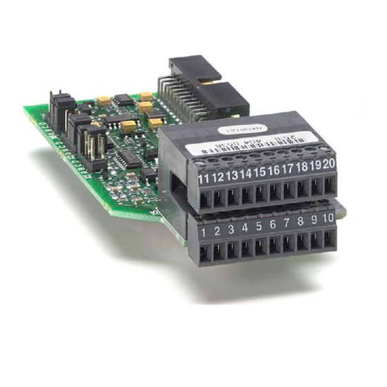
Vacon NXP series User Manual

Vacon NXP series User Manual

Basic i/o boards; expander i/o boards; adapter i/o boards
Hide thumbs Also See for NXP series:

Advertisement

vacon nx
®
ac drives
basic i/o boards
expander i/o boards
adapter i/o boards
user manual

Advertisement

Table of Contents
loading
Need help?

Need help?

Do you have a question about the NXP series and is the answer not in the manual?

Questions and answers

Subscribe to Our Youtube Channel

Summary of Contents for Vacon NXP series

  • Page 1 ® ac drives basic i/o boards expander i/o boards adapter i/o boards user manual...
  • Page 3: Table Of Contents

    ABLE OF ONTENTS Document: DPD00884B Release date : 1/9/16 General information..................2 Board slots on the control board of VACON® NXS and NXP ..........2 Board Slots on the control board of VACON® NXL............3 Option board types ......................4 Technical data ........................5 1.4.1 Isolation..........................6 1.4.2 Analogue inputs (mA/V) .....................6...
  • Page 4: General Information

    NXS and NXP ® The control board is situated inside the control unit of the VACON NX AC drive. There are five board slots (labelled A to E) on the control board of NXS and NXP (See NXS/P User Manual): The connectability of different option boards to different slots depends greatly on the type of the board.
  • Page 5: Board Slots On The Control Board Of Vacon® Nxl

    ® Board Slots on the control board of VACON ® Figure 2. Board slots on control board of VACON NXL. The control board of NXL includes fixed standard I/O and one place for option boards (see NXL User Manual of NXL). The most typical option board for NXL, OPT-AA, is specified in the NXL User Manual.
  • Page 6: Option Board Types

    • 4 General information Option board types ® The VACON option boards are divided in four groups according to their characteristics: types A, B, C and D. Short descriptions of the types below: OPTA_ • Basic boards used for basic I/O (NXS, NXP); normally pre-installed at the factory.
  • Page 7: Technical Data

    General information vacon • 5 Technical data The data in the table below applies to the inputs and outputs on all basic and expander boards. Table 1. Technical data Comply with EN50178, C-UL and EN60204-1 Safety (all boards) Inputs/outputs galvanically isolated; Isolation voltage...
  • Page 8: Isolation

    • 6 General information 1.4.1 Isolation The control connections are isolated from the mains potential and the I/O ground is connected directly to the frame of the AC drive. Digital inputs and relay outputs are isolated from the I/O ground.
  • Page 9: Digital Input Signal Conversion

    General information vacon • 7 Requirements for an external power back-up: output voltage +24DC±10%, max. ripple voltage 100mV RMS max. current 1A 1A external fuse (no internal short-circuit protection on the control board NOTE: Analogue outputs and inputs do not work with only +24V supplied to the control unit.
  • Page 10 • 8 General information If you use an external +24V the following arrangements are possible: External +24V +24V/EXT+24V Ground Jumper setting: = CMA isolated from GND 7226.emf Figure 5. Positive logic with external +24V when CMA is isolated from GND using onboard jumper. The...
  • Page 11: Hardware Protections

    General information vacon • 9 Hardware protections 1.5.1 Terminal block coding In order to avoid incorrect connections of terminal blocks to boards, some terminal blocks as well as related terminal connectors on the board are uniquely coded. For more information, see the description of the individual board.
  • Page 12: Type Identification Number

    Defining functions to inputs and outputs ® How to connect functions and the available I/O depends on the application you use. The VACON in One Application Package includes seven applications: Basic Application, Standard Application, PID Control Application, Multi-Step Speed Control Application, Local/Remote Control Application, Pump and Fan Control Application with Autochange and Multipurpose Control Application (see All- ®...
  • Page 13: Defining A Terminal For A Certain Function With Ncdrive Programming Tool

    General information vacon • 11 Once you have set the desired code, press the Enter button once to confirm the change. READY READY READY I/Oterm I/Oterm I/Oterm AI Ref Faul/Warn AI Ref Faul/Warn AI Ref Faul/Warn enter DigOUT:0.0 DigOUT:0.0 DigOUT:A.1 7230.emf...
  • Page 14: Option Board Related Parameters

    A to E with the Browser buttons to see what expander boards are connected. On the lowermost line of the display you also see the number of parameters associated with the board. Edit the ® parameter value as shown below. For more information on the keypad operation, see VACON NXS/ P User Manual. See Figure 9.
  • Page 15: Installation Of Vacon® Option Boards

    Installation of VACON® Option Boards vacon • 13 ® VACON NSTALLATION OF PTION OARDS Do not add or replace option boards or fieldbus boards on an AC drive with the power switched on. This may damage the boards. ® VACON NX AC drive.
  • Page 16 • 14 Installation of VACON® Option Boards Install the option board in a correct slot on the control board of the AC drive. On attaching (also removing) the board, hold it in horizontally straight position to avoid twisting the connector pins. See the photos below.
  • Page 17: Control Cables

    Installation of VACON® Option Boards vacon • 15 Control cables The control cables used must be at least 0.5mm screened multicore cables. The maximum terminal wire size is 2.5mm for the relay terminals and 1.5 mm for other terminals. Find the tightening torques of the option board terminals in the table below.
  • Page 18: Board Information Sticker

    • 16 Installation of VACON® Option Boards Board information sticker Each I/O option board package delivered by the factory includes a sticker (shown below) where possible modifications made in the AC drive are noted. Please check Option board (1), mark the board type (2), the slot into which the board is mounted (3) and the mounting date (4) on the sticker.
  • Page 19: Descriptions Of Vacon® Option Boards

    -10Vref -10…+10V -10…+10V +24V/ EXT+24V Encoder board can be used in VACON ® NXS with special applications only. DI = Digital input DO = Digital output TI = Thermistor input AI = Analogue input AO = Analogue output RO = Relay output Local contacts: http://drives.danfoss.com/danfoss-drives/local-contacts/...
  • Page 20: Opta1

    • 18 Descriptions of VACON® option boards 3.1.1 OPTA1 ® Figure 11. VACON OPTA1 option board Description: Standard I/O board with digital inputs/outputs and analogue inputs/outputs Allowed slots: Type ID: 16689 Terminals: Two terminal blocks (coded = mounting of blocks in wrong order prevented, terminals #1 and #12);...
  • Page 21 Descriptions of VACON® option boards vacon • 19 I/O terminals on OPTA1 (coded terminals painted black) Table 5. OPTA1 I/O terminals Parameter reference Terminal Technical information on keypad and NCDrive +10 Vref Reference output +10V; Maximum current 10 mA Selection V or mA with jumper block X1 (see page 20): Default: 0–...
  • Page 22 • 20 Descriptions of VACON® option boards Jumper selections There are four jumper blocks on the OPTA1 board. The factory defaults and other available jumper selections are presented below. Jum per block X 1 : Jum per block X 2 :...
  • Page 23: Opta2

    Descriptions of VACON® option boards vacon • 21 OPTA1 parameters Table 6. OPTA1 board-related parameters Number Parameter Default Note 1 = 0...20mA 2 = 4...20mA AI1 mode 3 = 0...10V 4 = 2...10V 5 = -10...+10V 1 = 0...20mA 2 = 4...20mA AI2 mode 3 = 0...10V...
  • Page 24: Opta3

    125VDC/0.4A Min. switching load 5V/10mA 3.1.3 OPTA3 7245.emf Description: ® Relay board with two relay outputs and one thermistor input for VACON AC drive Allowed slots: Type ID: 16691 Terminals: Three terminal blocks; Screw terminals (M3); No coding. Jumpers: None Board parameters: None Local contacts: http://drives.danfoss.com/danfoss-drives/local-contacts/...
  • Page 25: Opta4

    Descriptions of VACON® option boards vacon • 23 I/O terminals on OPTA3 Table 8. OPTA3 I/O terminals Parameter reference Terminal Technical information on keypad and NCDrive Relay output 1 (NO/NC) RO1/normal closed Switching capacity 24VDC/8A RO1/common DigOUT:B.1 250VAC/8A RO1/normal open 125VDC/0.4A...
  • Page 26 • 24 Descriptions of VACON® option boards Description: ® Encoder board for VACON NXP. Encoder input board with programmable control voltage for an encoder. The encoder board OPTA4 is for TTL type encoders (TTL, TTL(R)) providing input signal levels that meet the RS_422 interface standard. Encoder inputs A, B and Z are not galvanically isolated.
  • Page 27 Descriptions of VACON® option boards vacon • 25 Technical data: Encoder control voltage, +5V/+15V/+24V Control voltage selectable with jumper X4. Max. input frequency ≤150kHz Inputs A, B and Z are differential Encoder input connections, Encoder inputs are RS-422 interface compatible inputs A+, A–, B+, B–, Z+, Z–...
  • Page 28 **+5V/15V/+24V 7248.emf Figure 13. RS-422 type encoder connection using differential inputs NOTE: ® The encoder pulses are handled by VACON software as presented below: OUTPUT SIGNALS Clockwise, seen from shaft 360º el. 1 period 90º el. (channel separation) 7249.emf...
  • Page 29 Descriptions of VACON® option boards vacon • 27 OPTA4 parameters Table 10. OPTA4 board-related parameters Number Parameter Default Note 7.3.1.1 Pulse/revolution 65535 1024 0 = No 7.3.1.2 Invert direction 1 = Yes Time used to calculate speed actual value. NOTE: Use value 1 in Closed Loop mode.
  • Page 30 • 28 Descriptions of VACON® option boards +25 Hz -25 Hz 7251.emf 3 = A = Forw, B = Rev This type cannot be used for Closed Loop control! In this mode both channels are receiving signal but not at the same time.
  • Page 31: Opta5

    Descriptions of VACON® option boards vacon • 29 3.1.5 OPTA5 Jumpers 7253.emf Description: ® Encoder board for VACON NXP. Encoder input board with programmable control voltage for an encoder. The OPTA5 board is designed for HTL (High voltage Transistor Logic) type...
  • Page 32 • 30 Descriptions of VACON® option boards I/O terminals on OPTA5 (coded terminal painted black) Table 11. OPTA5 I/O terminals Parameter reference Terminal Technical information Keypad/NCDrive DIC1A+ Pulse input A (differential); Voltage range 10…24V DIC1A– Pulse input B; phase shift of 90 degrees compared to DIC2B+ Pulse input A (differential);...
  • Page 33 Descriptions of VACON® option boards vacon • 31 Jumper selections On the OPTA5 board, there are four jumper blocks; X4 is used to program the control voltage (auxiliary voltage), X2, X5 and X6 are set according the voltage of the encoder. The factory default and other available jumper selections are presented below.
  • Page 34 • 32 Descriptions of VACON® option boards Encoder connection – Single-ended 15V/24V from the OPT-A5- OPT-A5 Twisted pairs board or from external supply* board with own shield +15V/+24V DIC1A+ Encoder DIC1A- DIC2B+ DIC2B- DIC3Z+ DIC3Z- ENC1Q *If external supply is used remember...
  • Page 35: Opta7

    Descriptions of VACON® option boards vacon • 33 3.1.6 OPTA7 Jumper X4 Jumper X5 Jumpers X15 and X16 7258.emf Description: ® Duplicate encoder board for VACON NXP. Encoder input board with programmable control voltage for the encoder. The OPTA7 board is designed for HTL (High voltage Transistor Logic) type...
  • Page 36 • 34 Descriptions of VACON® option boards I/O terminals on OPTA7 Table 12. OPTA7 I/O terminals Parameter reference Terminal Technical information Keypad/NCDrive DIC1A+ Pulse input A (differential); Voltage range 10…24V DIC1A– Pulse input B; phase shift of 90 degrees compared to DIC2B+ Pulse input A (differential);...
  • Page 37 Descriptions of VACON® option boards vacon • 35 Technical data: Encoder control voltage, +15V/+24V Control voltage selectable with jumper X4. Max. input frequency ≤150kHz Encoder input connections, inputs A+, A–, B+, B–, Z+, Z– Inputs A, B and Z are differential Max.
  • Page 38 • 36 Descriptions of VACON® option boards Jumper blocks X15 and X16: Jumper block X5: Master/Slave Encoder channel function Channel DIC Channel DID selected selected Master function Slave function selected selected Jumper block X4: Auxiliary voltage level 2 4 V...
  • Page 39 Descriptions of VACON® option boards vacon • 37 Encoder connection The figures below present examples of a chain connection of several OPTA7 boards (Figure 17) and a connection of two encoders to the OPTA7 option board (Figure 18). OPT-A7 +15V/+24V...
  • Page 40 • 38 Descriptions of VACON® option boards OPTA-7 15V/24V from OPT-A7 +15V/+24V DIC1A+ Encoder 1 DIC1A- DIC2B+ DIC2B- DID1A+ DID1A- Encoder 2 DID2B+ DID2B- DOD1A+ DOD1A- DOD2B+ DOD2B- 7261.emf Figure 18. Connection of two encoders to OPTA7 board OPTA7 parameters Table 13.
  • Page 41: Opta8

    Descriptions of VACON® option boards vacon • 39 OPTA7 monitoring values Table 14. OPTA7 monitoring values Number Monitored value Unit Description Mon 7.3.2.1 Encoder 1 frequency Motor speed in Hz calculated from encoder 1 pulses Motor speed in rpm calculated from encoder 1 Mon 7.3.2.2...
  • Page 42 • 40 Descriptions of VACON® option boards I/O terminals on OPTA8 (coded terminals painted black) Table 15. OPTA8 I/O terminals Parameter reference Terminal Technical information Keypad/NCDrive +10 Vref Refer.output +10V; Max.current 10mA; Decoupled from FC GND Selection V or mA with jumper block X1 (see page 41): Default: 0–...
  • Page 43 Descriptions of VACON® option boards vacon • 41 Jumper selections There are four jumper blocks on the OPTA8 board. The factory defaults and other available jumper selections are presented below. Jum per block X 1 : Jum per block X 2 :...
  • Page 44: Opta9

    • 42 Descriptions of VACON® option boards OPTA8 parameters Table 16. OPTA8 board-related parameters Number Parameter Default Note 1 = 0...20mA 2 = 4...20mA AI1 mode 3 = 0...10V 4 = 2...10V 5 = -10...+10V 1 = 0...20mA 2 = 4...20mA AI2 mode 3 = 0...10V...
  • Page 45: Optal

    Descriptions of VACON® option boards vacon • 43 I/O terminals on OPTA9 See page 19. Jumper selections See page 20. OPTA9 parameters See page 21. 3.1.9 OPTAL Description: Dual I/O expander board with six 42…240 VAC digital inputs, 2 analog inputs, two analog outputs, one digital output and 15 and 24 V out.
  • Page 46 • 44 Descriptions of VACON® option boards I/O terminals on OPTAL Table 17. OPTAL I/O terminals Parameter reference Terminal Technical information Keypad/NCDrive +15 V 15 V out – together with terminal 2 max 200 mA +15 V 15 V out An.IN:A.1...
  • Page 47: Optae

    Descriptions of VACON® option boards vacon • 45 3.1.10 OPTAE Jumper X4 7266.emf Description: ® Encoder board for VACON NXP. Encoder input board with programmable control voltage for an encoder. The OPTAE board is designed for HTL (High voltage Transistor Logic) type...
  • Page 48 • 46 Descriptions of VACON® option boards I/O terminals on OPTAE (coded terminal painted black) Table 18. OPTAE I/O terminals Parameter reference Terminal Technical information Keypad/NCDrive DIC1A+ Pulse input A (differential); Voltage range 10…24V DIC1A– Pulse input B; phase shift of 90 degrees compared to DIC2B+ Pulse input A (differential);...
  • Page 49 Descriptions of VACON® option boards vacon • 47 Usage: Closed Loop Vector Control. The OPTAE board is mainly used in conventional industrial applications where encoder cable lengths are relatively long. Encoder connection - single-ended 15V/24V from the OPT-AE OPT-AE Twisted pairs...
  • Page 50 • 48 Descriptions of VACON® option boards Encoder connection – differential 15V/24V from the OPT-AE OPT-AE board or from external supply* board +15V** +15V/+24V DIC1A+ Encoder DIC1A- DIC2B+ DIC2B- DIC3Z+ DIC3Z- ENC1Q DIC1 **+15V/+24V 7270.emf Figure 22. HTL type encoder connection using differential inputs OPTAE parameters Table 19.
  • Page 51: Optan

    Descriptions of VACON® option boards vacon • 49 3.1.11 OPTAN 7271.emf Description: ® Standard I/O board for VACON NXP with 6 galvanically isolated digital inputs and two analogue inputs/outputs. The Analogue channels are programma- ble: 1 = 0...20mA 2 = 4...20mA 3 = 0...10V...
  • Page 52 • 50 Descriptions of VACON® option boards I/O terminals on OPTAN Table 20. OPTAN I/O terminals Terminal Technical information Selection V or mA with jumper block J1 AI1- Default: 0– +10V (Ri = 200 kΩ) (-10V..+10V Joy-stick control, selected with jumper) 0–...
  • Page 53 Descriptions of VACON® option boards vacon • 51 Jumper selections A B C D A B C D A B C D A B C D 7272.emf J1 (AI1), J2 (AI2) Analog Input Mode 0 ... 10 D (default) J1 (AI1), J2 (AI2) Analog Input Mode –10 ...
  • Page 54 • 52 Descriptions of VACON® option boards Table 21. OPTAN board-related parameters Number Parameter Default Note 1 = 0...20mA 2 = 4...20mA 7.1.1.4 AO2 mode 3 = 0...10V 4 = 2...10V 5 = -10...+10V OPTAN board I/O monitor values Table 22.
  • Page 55: I/O Expander Boards Optb

    • This board type can normally be plugged into slots B, C, D or E. ® The number of control inputs and outputs on your VACON AC drive can be increased with the I/O Expander boards. This kind of boards can usually be placed in any board slot inside the AC drive control unit except for slot A.
  • Page 56: Optb1

    • 54 Descriptions of VACON® option boards 3.2.1 OPTB1 Jumper X2 Jumper X4 7273.emf Description: ® VACON NX I/O expander board with six bidirectional terminals. Allowed slots: B, C, D, E Type ID: 16945 Terminals: One terminal block; Screw terminals (M2.6); No coding Jumpers: 2;...
  • Page 57 Descriptions of VACON® option boards vacon • 55 Table 24. OPTB1 I/O terminals Parameter reference Terminal Technical information Keypad/NCDrive Control voltage output; Voltage for switches etc.; +24V max. current 150mA; Short-circuit protected. Jumper selections On the OPTB1 board, there are two jumper blocks. The jumper block X2 is used to define the bidirectional terminal as either input or output.
  • Page 58: Optb2

    • 56 Descriptions of VACON® option boards 3.2.2 OPTB2 7275.emf Description: ® VACON NX I/O expander board with a thermistor input and two relay out- puts. Allowed slots: B, C, D, E Type ID: 16946 Terminals: Three terminal blocks; Screw terminals (M3); No coding...
  • Page 59: Optb4

    Descriptions of VACON® option boards vacon • 57 3.2.3 OPTB4 7276.emf Description: ® VACON NX I/O expander board with one galvanically isolated analogue input and two galvanically isolated analogue outputs (standard signals 0(4)…20mA). Allowed slots: B, C, D, E Type ID:...
  • Page 60: Optb5

    • 58 Descriptions of VACON® option boards I/O terminals on OPTB4 Table 26. OPTB4 I/O terminals Parameter reference Terminal Technical information Keypad/NCDrive AI1+ AnIN:X.1 0(4)…20mA; R =250Ω; galvanically isolated Resolution 10 bits/0.1%; Accuracy ±1% of the full dis- AI1–...
  • Page 61 Descriptions of VACON® option boards vacon • 59 I/O terminals on OPTB5 Table 27. OPTB5 I/O terminals Parameter reference Terminal Technical information Keypad/NCDrive Switching capacity 24VDC/8A RO1/common 250VAC/8A DigOUT:X.1 RO1/normal open 125VDC/0.4A Min. switching load 5V/10mA Switching capacity 24VDC/8A RO2/common 250VAC/8A DigOUT:X.2...
  • Page 62: Optb8

    • 60 Descriptions of VACON® option boards 3.2.5 OPTB8 Jumper block X2 7278.emf Description: Temperature measuring board with three Pt-100 sensor (3-wire) inputs. The measurable temperature range is –30...200 Cº on Pt-100 input. Both 3-wire and 2-wire elements can be used.
  • Page 63 Descriptions of VACON® option boards vacon • 61 Table 28. OPTB8 I/O terminals Parameter reference Terminal Technical information Keypad/NCDrive Not connected OPTB8 accuracy The following table represents the results of accuracy measurements in laboratory environment. In the tests we used Draga JAMAK cable. The testing covered different sensor setups.
  • Page 64 • 62 Descriptions of VACON® option boards Jumper selections 1 2 3 1 2 3 1 2 3 1 Sensor 2 Sensors 3 Sensors = F actory default 7280.emf Up to three PT100 sensors can be connected to the third PT100 input. You can select the number of sensors in use with jumper block X2: Local contacts: http://drives.danfoss.com/danfoss-drives/local-contacts/...
  • Page 65: Optb9

    Descriptions of VACON® option boards vacon • 63 3.2.6 OPTB9 7281.emf Description: I/O expander board with five 42…240 VAC digital inputs and one normal relay output. Allowed slots: B, C, D, E Type ID: 16953 Terminals: One terminal block; Screw terminals (M2.6); No coding...
  • Page 66: Optbb

    • 64 Descriptions of VACON® option boards depending on the slot which the expander board is plugged into. See chapter 1.7. 3.2.7 OPTBB X6 X7 Jumper block X11 Main board Secondary board 7282.emf Description: ® Absolute encoder board for VACON NXP with inputs for an Endat type encoder.
  • Page 67 Descriptions of VACON® option boards vacon • 65 Sinus signals require some precautions for noise immunity that may be a little more demanding than conventional square wave encoders. Use of twisted pairs (possibly with individual shielding of each pair) is recommended. Use one pair for sinus+ and sinus-, another pair for cosinus+ and cosinus-, another pair for data+ data- of the absolute serial channel, another pair for clock+ and clock- of absolute channel.
  • Page 68 • 66 Descriptions of VACON® option boards Jumper selections On the OPTBB board, there is one jumper block used to program the control voltage (auxiliary voltage). The factory default and other available jumper selections are presented below. Jumper block X 1 1...
  • Page 69 Descriptions of VACON® option boards vacon • 67 OPTBB board parameters Table 33. OPTBB board parameters Code Parameter Default Selections Description 0 = No 7.3.1.1 Reverse Manually selectable rotation direction 1 = Yes 0 = Not used 1 = 1 ms Incremental pulse reading rate.
  • Page 70 • 68 Descriptions of VACON® option boards OPTBB option board status LEDs Yellow LED Meaning Option board not activated Option board in initialisation state waiting for activation command from the AC drive Blinking fast Option board is activated and in RUN state (once/sec) •...
  • Page 71: Optbh

    Descriptions of VACON® option boards vacon • 69 3.2.8 OPTBH 3025.emf Description: Temperature measurement board with three individual channels. Allowed slots: B, C, D, E Supported sensors: PT100, PT1000, NI1000, KTY84-130, KTY84-150, KTY84-131 Type ID: 16968 Terminals: One terminal block; Screw terminals (M3); No coding...
  • Page 72 • 70 Descriptions of VACON® option boards Table 37. PT100, KTU84 and Ni1000 (Ni1000 DIN) accuracy for OPTBH Cable length (m) 3-wire 2-wire Accuracy (°C) ≤300 -1 < x < 1 -1 < x < 5 -1 < x < 3 Connecting Temperature sensors to OPTBH option board: Use shielded cables and connect the cable shield to grounding clamp in the drive.
  • Page 73: Adapter Boards Optd

    Monitor Bus adapter board for OPTD6 B,D,E ® VACON 3.3.1 OPTD1 Description: ® System Bus adapter board for VACON Allowed slots: D, E Type ID: 17457 Terminals: Double optical input and output terminals. Agilent HFBR-1528 (Receiver), HFBR-2528 (Transmitter). Jumpers: None Board parameters: None Local contacts: http://drives.danfoss.com/danfoss-drives/local-contacts/...
  • Page 74 • 72 Descriptions of VACON® option boards I/O terminals on OPTD1 Table 39. OPTD1 I/O terminals Terminal Technical information System Bus optical input 1 (RX1) Use 1-mm optical cable (e.g. Agilent HFBR-RUS500 & HFBR-4531/4532/ 4533 connectors) System Bus optical input 2 (RX2) Use 1-mm optical cable (e.g.
  • Page 75: Optd2

    This figure presents the layout of D2 board version H or later. See Chapter Jumper selections below. Description: ® System Bus adapter board for VACON NXP with single optical input and output; Interface to fast monitor bus used by the NCDrive PC tool. Allowed slots: (B,)D, E;...
  • Page 76 • 74 Descriptions of VACON® option boards I/O terminals on OPTD2 Table 41. OPTD2 I/O terminals Terminal Technical information System Bus optical input 1 (RX1) Use 1-mm optical cable (e.g. Agilent HFBR-RUS500 & HFBR-4531/4532/ 4533 connectors) NOTE: Not available if the board is placed in slot B System Bus optical output 1/2 (TX1/TX2);...
  • Page 77 Descriptions of VACON® option boards vacon • 75 Jumper block X3: CAN grounding A: Connected to ground B: Connected to ground via LC filter C: Connected to CAN isolated ground Not assembled: No connection See further clarifications of the alternatives next page! 7288.emf...
  • Page 78 • 76 Descriptions of VACON® option boards Alternative connection of “CAN GND” signal: connect ‘CAN GND’ together between all nodes. Use the signal wire inside the shield for this purpose, see figure below: Shield CAN HI CAN HI CAN LO...
  • Page 79: Optd3

    Descriptions of VACON® option boards vacon • 77 OPTD2 OPTD2 OPTD2 OPTD2 Jumper X5 : TX1 Jumper X5 : TX2 Jumper X5 : TX2 Jumper X5 : TX2 Master Follower Follower Follower SBInUse = Yes SBID SBInUse = Yes SBInUse...
  • Page 80 • 78 Descriptions of VACON® option boards I/O terminals on OPTD3 Table 43. OPTD3 I/O terminals Terminal Technical information Transmit data Receive data Ground isolated +9V isolated NOTE: If OPTCI Ethernet Option board is used for NC Tools connection, like NCLoad, the OPTD3 board cannot be used.
  • Page 81: Optd6

    This figure presents the layout of D6 board version F or later. See Chapter Jumper selections below. Description: ® Monitor Bus adapter board for VACON NXP. Interface to fast monitor bus used by the NCDrive PC tool. Allowed slots: B, D, E.
  • Page 82 • 80 Descriptions of VACON® option boards Jumper block X3: Jumper block X4: CAN grounding CAN termination Connected to shield Not connected to shield Terminated Not terminated = Factory default 7295.emf Figure 30. Jumper selections for OPTD6, up to version E.
  • Page 83: Vacon® Option Boards - Operational Details

    ® VACON OPTION BOARDS – OPERATIONAL DETAILS ® Table 46. VACON option boards, types A and B Board Slots +24V/ AI (mA), +10V (Enc. Pt-100 (Enc. type allowed DI DO (mA), +15V/ +15/ isol. (mA/V) (no) (mA/V) (no/nc) RS-422) isol.
  • Page 84 ® Table 47. VACON option boards, type D Adapter boards NXOPTD_ OPTD1 17457 System Bus adapter board: 2 x fiber optic pairs (B)DE 17458 System Bus adapter board: 1 x fiber optic pair & CAN bus adapter (galvanically decoupled) OPTD2...
  • Page 85 VACON® Option Boards – operational details vacon • 83 ® Table 48. All in One applications and supported VACON NX option boards NXS, NXP Board type Local- Multi-step Multi- Basic boards Basic Standard Remote speed purpose Multi-control OPTA_ NXFIFF01 NXFIFF02...
  • Page 86 Document ID: Vacon Ltd DPD00884B Member of the Danfoss Group Rev. B Runsorintie 7 65380 Vaasa Sales code: DOC-IOboards+DLUK Finland...

Table of Contents

Save PDF