
Related Manuals for Vacon optbj


Summary of Contents for Vacon optbj
- Page 1 100 industrial ® vacon 100 flow ® vacon 100 hvac ® ac drives optbj sto and atex option board safety manual...
-
Page 3: Table Of Contents
OPTBJ board layout..................15 Identifying board revision....................15 OPTBJ board jumpers......................16 STO jumper on the VACON® 100 family AC drive ............17 Cuttable jumper to separate control ground from PE ............18 STO and SS1 safety functions .................19 Safe Torque Off (STO) principle ..................20 Safe Stop 1 (SS1) Principle ....................22... -
Page 4: Approvals
EU DECLARATION OF CONFORMITY Danfoss A/S Vacon Ltd declares under our sole responsibility that the Product name Vacon OPTBJ option board to be used with Vacon 100 family products Product identification 70CVB01380 Product Safety Functions Safe Torque Off (Specified in EN 61800-5-2) fulfils all of the relevant safety component requirements of EC Machinery Directive 2006/42/EC. - Page 5 Approvals vacon • 5 Local contacts: https://www.danfoss.com/en/contact-us/contacts-list/...
- Page 6 • 6 Approvals Local contacts: https://www.danfoss.com/en/contact-us/contacts-list/...
- Page 7 Approvals vacon • 7 Local contacts: https://www.danfoss.com/en/contact-us/contacts-list/...
- Page 8 • 8 Approvals Local contacts: https://www.danfoss.com/en/contact-us/contacts-list/...
- Page 9 Approvals vacon • 9 Local contacts: https://www.danfoss.com/en/contact-us/contacts-list/...
-
Page 10: General
NOTE! Designing of safety-related systems requires special knowledge and skills. Only qualified persons are permitted to install and set up the OPTBJ board. ® This document covers the OPTBJ option board 70CVB01380 functionality together with VACON family Control board 70CVB01582. ®... -
Page 11: References
• A safety relay providing a reset function NOTE! The safety functions of OPTBJ do not comply with Emergency Switching Off according to EN 60204-1. NOTE! Do not use the STO function as a standard stop function of the drive. -
Page 12: Installation Of Optbj Board
Boards that are compatible for VACON 100 family AC drives have two codings ® that enable the placing of the board (see above): one for VACON 100 family compatibility (A), and another for the slot-specific placing (B). Local contacts: https://www.danfoss.com/en/contact-us/contacts-list/... - Page 13 NOTE! See Chapter 4.2 for the jumper settings! 3041A_00 If shielded cable is used, ground the shield of the OPTBJ cable to the frame of the drive by using the grounding clamp for control cable included in the delivery of the drive.
- Page 14 Remount the AC drive cover and run the cable as shown in picture. NOTE: When planning the cable runs, remember to keep the distance between OPTBJ cables and the motor cable at a minimum of 30 cm. It is rec- ommended to route the OPTBJ cables away from the power cables as shown in the picture.
-
Page 15: Optbj Board Layout
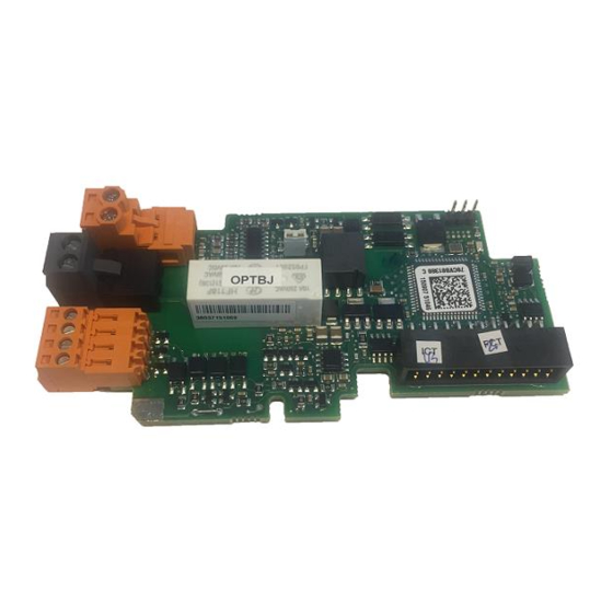
Figure 1. OPTBJ board layout Identifying board revision The revision of OPTBJ board can be identified by checking the revision letter on the matrix bar code sticker. Revision letter is written after the board type code. For example, '70CVB01380 D' indicates that the board is of revision D. -
Page 16: Optbj Board Jumpers
• 16 OPTBJ board layout OPTBJ board jumpers There are two pin headers for jumpers on the OPTBJ option board. The jumper settings are de- scribed below: Jumper X23, short circuit supervision Short circuit supervision ON Short circuit supervision OFF... -
Page 17: Sto Jumper On The Vacon® 100 Family Ac Drive
® STO jumper on the VACON 100 family AC drive STO JMP 3049A_00 ® Figure 4. STO jumper location on VACON 100 family AC drive. Open the main cover and the inner cover to reveal the jumper. Local contacts: https://www.danfoss.com/en/contact-us/contacts-list/... -
Page 18: Cuttable Jumper To Separate Control Ground From Pe
PE through high impedance. In some systems, the control ground may need to be separated from PE when the OPTBJ board is installed. Do not do this before consulting the Danfoss support personnel (contact the Danfoss local contacts at http://drives.danfoss.com/ danfoss-drives/local-contacts/). -
Page 19: Sto And Ss1 Safety Functions
• 19 SAFETY FUNCTIONS The safety functions of the OPTBJ board, such as the technical principle and data, wiring examples and commissioning, will be described in this chapter. NOTE! The use of STO, SS1 or other safety functions does not itself ensure safety. An overall risk evaluation is required in order to make sure that the commissioned system is safe. -
Page 20: Safe Torque Off (Sto) Principle
Safe Torque Off (STO) principle The STO safety function of the OPTBJ board allows the drive output to be disabled so that the drive cannot generate torque in the motor shaft. For STO, the OPTBJ board has two separate, galvanically isolated inputs STO1 and STO2. - Page 21 Atex Safety Function STO1 STO2 SLAVE MASTER POWER UNIT POWER UNIT Hardware Hardware Hardware Hardware STO 1 STO 2 STO 1 STO 2 11654A_uk ® Figure 7.STO principle with OPTBJ board and VACON 100 family control board MR12 Local contacts: https://www.danfoss.com/en/contact-us/contacts-list/...
-
Page 22: Safe Stop 1 (Ss1) Principle
STO safety function. These two subsystems combined compose the Safe Stop 1 safety function as shown in Figure 9. Safe Stop 1 (SS1) Time Delayed Safety Relay Vacon 100 Safe Torque Off (STO) Subsystem Subsystem Safety Relay 11579_uk Figure 9. - Page 23 • The stop function of the drive needs to be correctly set for the process/ machine. Activating the SS1 safety function must execute the configured ® stop in the drive. In the VACON 100 default application software it is rec- 13006.emf ommended to use the "Quick Stop"...
-
Page 24: Technical Details
STO function. The STO inputs of OPTBJ are OSSD tolerant. The operation of OPTBJ is not interfered by test pulses that are generated to the STO lines by the connected safety actuator as long as the test pulses fulfill certain requirements. -
Page 25: External Light Test Pulse Filtering Capability
The thermistor input is disabled by making a short circuit to the ter- minals and setting the jumper X23 in "OFF" state. The thermistor input operation and instructions are presented in chapter 8.1. Table 6. OPTBJ I/O terminals Terminal Technical information... -
Page 26: Relay Output
• 26 STO and SS1 safety functions Table 7. STO function truth table STO state STO1+ STO1- STO2+ STO2- 0VDC 0VDC STO active STO diagnostic fault and STO activation. Fault is activated after 24VDC 0VDC inputs have been in different states for >500 ms. -
Page 27: Safety-Related Data According To The Standard
STO and SS1 safety functions vacon • 27 5.3.7 Safety-related data according to the standard Table 8. Safe Torque Off (STO) safety-related data * MR4 - MR10 MR12 SIL 3 SIL 3 PFH = 4.12 /hour PFH = 4.30 /hour... - Page 28 • 28 STO and SS1 safety functions Safe Stop (SS1) safety-related data NOTE! The following chapter is only an informative example of combining products. The SS1 safety function consists of two subsystems with different safety-related data.The subsys- tem consisting of the time delayed safety relay is manufactured, for example, by PHOENIX CON- TACT.
-
Page 29: Commissioning
• The wiring should be done according to the general wiring instructions for the specific prod- uct where OPTBJ is installed. See wiring examples in the figures 11, 12 and 13. • If shielded cable is used, the shield must be connected to the drive's lid (PE) using a ground- ing clamp. - Page 30 • 30 Commissioning OPTBJ SAFETY ACTUATOR CHANNEL 1 +24V STO1+ SW P STO1- SW M OPTBJ +24V CHANNEL 2 STO2+ STO2- 11852_uk Figure 12. STO connection example 2 OPTBJ SAFETY ACTUATOR CHANNEL 1 +24V STO1+ SW P +24V STO1-...
- Page 31 Commissioning vacon • 31 Individual pair Overall shield Cable jacket (Optional) Pair shield 11860_uk Figure 14. Structure of cable with two individually shielded twisted pairs Table 9. Recommended maximum cable lengths Used STO input connection Diagnostics on safety Safety actuator type...
-
Page 32: Wiring Examples
The figure above shows a connection example of OPTBJ board for Safe Torque Off safety function without reset. The switch S1 is connected with 4 wires to the OPTBJ board as shown above. When the switch S1 is activated (contacts open), the drive goes to STO state and motor (if running) will stop by coasting. - Page 33 The figure above presents a connection example of OPTBJ board for STO safety function with reset. The switch S1 is connected with 4 wires to the OPTBJ board as shown above. The digital input 3 (DIN3), for example, is wired for the fault reset function. The reset function (not part of any safety function) can be programmed to any of the available digital inputs.
- Page 34 The external safety relay module is connected to the switch S1. The used power supply to switch S1 is 230 VAC as an example. The safety relay module is connected to OPTBJ board with 4 wires as shown in Figure above.
- Page 35 Commissioning vacon • 35 More information on the safety relay module may be found in the safety relay documentation. NOTE! According to EN 60204-1 (Safety of machinery - Electrical equipment of machines), the re- setting of the emergency stop request (e.g. releasing of emergency stop button) must not restart the drive.
-
Page 36: Parameterization Of Sto Functionality
• 36 Commissioning Parameterization of STO functionality STO functionality is based on hardware, and cannot be bypassed by parameterization. Activating ei- ther or both of STO input channels by applying logical '0' causes a coasting stop for the motor and prevents the restart. -
Page 37: Checklist For Commissioning The Optbj Board
Step Has a risk assessment of the system been carried out to ensure that us- ing the OPTBJ board Safe Torque Off (STO) or Safe Stop 1 (SS1) safety function is safe and according to the local regulations ? Does the assessment include an examination of whether using external... -
Page 38: Testing The Safe Torque Off (Sto) Or Safe Stop 1 (Ss1) Safety Functions
• 38 Commissioning Testing the Safe Torque Off (STO) or Safe Stop 1 (SS1) safety functions NOTE! Before testing the STO or SS1 safety functions, make sure that the checklist (Chapter 6.2) is inspected and completed. NOTE! After connecting the board ALWAYS make sure that the STO or SS1 safety functions are working properly by testing them before operating the system. -
Page 39: Maintenance
• 39 AINTENANCE CAUTION! If any service or repair is to be conducted on the drive installed with OPTBJ board please follow the check list given in Chapter 6.2. 13006.emf CAUTION! During maintenance breaks, or in case of service/repair, the OPTBJ board might have to be removed from its slot. - Page 40 • Restart the drive. • If the restart does not help, check the wiring: Both STO input channels of OPTBJ need to be on the same state, i.e. safety device controlling the There is a diagnostic failure in inputs needs to feed or cut the STO safety function.
-
Page 41: Thermistor Function (Atex)
It can be used as an overtemperature tripping device for motors in explosive area (EX motors). NOTE! The OPTBJ board also contains the Safe Torque Off (STO) safety function. When STO is not intended to be used, inputs STO1+(OPTBJ:1), STO2+(OPTBJ:3) are to be connected to +24V (for ex- ®... - Page 42 Danfoss A/S Vacon Ltd declares under our sole responsibility that the Product name Vacon OPTBJ option board to be used with Vacon 100 family products Product identification 70CVB01380 Marking of the equipment has been designed in conformity with the requirements of the Council directive for explosive atmospheres, 94/9/EC of March 1994 (until April 19th, 2016), 2014/34/EU (from April 20th, 2016) according to following standards.
- Page 43 Control board Atex Safety Thermistor Function Atex Safety Function STO1 STO2 POWER UNIT Hardware Hardware STO 1 STO 2 11575B uk ® Figure 15. Thermistor function principle in VACON 100 family AC drive with the OPTBJ board, MR4-10 Local contacts: https://www.danfoss.com/en/contact-us/contacts-list/...
- Page 44 Atex Safety Function STO1 STO2 SLAVE MASTER POWER UNIT POWER UNIT Hardware Hardware Hardware Hardware STO 1 STO 2 STO 1 STO 2 11654A_uk ® Figure 16.STO principle with OPTBJ board and VACON 100 family control board MR12 Local contacts: https://www.danfoss.com/en/contact-us/contacts-list/...
-
Page 45: Technical Data
8.1.1 Functional description The thermistor supervision circuit of the OPTBJ board is designed to provide a reliable way of dis- abling the drive modulation in case there is an overtemperature at the motor thermistor(s). By disabling the drive modulation, the feeding of the energy to the motor is prevented and a further heating up of the motor due to this is avoided. -
Page 46: Short Circuit Monitoring
NOTE! Installation, testing and service work on the OPTBJ board can be performed only by qualified persons. NOTE! It is not allowed to perform any repair work on the OPTBJ board. Return faulty boards to the manufacturer for analysis. NOTE! It is recommended to test the ATEX functionality using thermistor input on OPTBJ board pe- riodically (typically once a year). - Page 47 Document ID: Vacon Ltd DPD00470E Member of the Danfoss Group Rev. E Runsorintie 7 65380 Vaasa Sales code: DOC-OPTBJ+DLUK Finland...
Need help?
Do you have a question about the optbj and is the answer not in the manual?
Questions and answers