Juniper MX2020 Hardware Manual
3d universal edge router
Hide thumbs
Also See for MX2020:
- Hardware manual (454 pages) ,
- Hardware manual (800 pages) ,
- Quick start manual (72 pages)
Table of Contents
Advertisement
Quick Links
Download this manual
See also:
Hardware Manual
Advertisement
Table of Contents
Troubleshooting

Related Manuals for Juniper MX2020


Summary of Contents for Juniper MX2020
- Page 1 MX2020 3D Universal Edge Router Hardware Guide Modified: 2015-11-18 Copyright © 2015, Juniper Networks, Inc.
- Page 2 END USER LICENSE AGREEMENT The Juniper Networks product that is the subject of this technical documentation consists of (or is intended for use with) Juniper Networks software. Use of such software is subject to the terms and conditions of the End User License Agreement (“EULA”) posted at http://www.juniper.net/support/eula.html.
-
Page 3: Table Of Contents
MX2020 Component Redundancy ........ - Page 4 MX2020 Cable Manager Description ........45...
- Page 5 MX2020 Chassis Moving Guidelines ........107...
- Page 6 Verifying the MX2020 Parts Received ........199...
- Page 7 Modules on the MX2020 Router ........256...
- Page 8 Installing an MX2020 Adapter Card ........
- Page 9 Maintaining the MX2020 Air Vents ....... . 344 Maintaining the MX2020 Air Filter ....... . . 344 Maintaining the MX2020 Air Baffle .
- Page 10 Removing the MX2020 Air Filter ........
- Page 11 Removing the MX2020 Air Baffle ........475...
- Page 12 MX2020 3D Universal Edge Router Hardware Guide Troubleshooting the MX2020 Power Subsystem ......541 Chapter 28 Contacting Customer Support and Returning the Chassis or Components .
- Page 13 Devices ............583 TN Power Warning for MX2020 Routers ....... . 583 MX2020 AC Power Electrical Safety Guidelines .
- Page 14 MX2020 3D Universal Edge Router Hardware Guide Copyright © 2015, Juniper Networks, Inc.
- Page 15 Figure 12: MX2020 Router ESD Points ........
- Page 16 Figure 35: MPC Edges ..........73 Figure 36: MX2020 Interface Port Mapping ......80 Chapter 9 Power Subsystem .
- Page 17 Figure 79: Unpacking the MX2020 ........
- Page 18 Figure 105: Attaching Winch Strap to Winch Strap Plate ....234 Figure 106: Pulling the MX2020 into the Rack ......235 Figure 107: Reinstalling an AC Power Distribution Module .
- Page 19 Figure 173: Air Baffle ..........370 Figure 174: Upper and Lower Cable Manager Cable Routing ....385 Copyright © 2015, Juniper Networks, Inc.
- Page 20 Figure 211: Installing a DC Power Distribution Module ..... 460 Figure 212: Connecting DC Power to the MX2020 Router ....462 Figure 213: Connecting Power Cables to the DC Power Distribution Module .
- Page 21 General Safety Guidelines and Warnings ......553 Figure 251: Placing a Component into an Electrostatic Bag ....558 Copyright © 2015, Juniper Networks, Inc.
- Page 22 MX2020 3D Universal Edge Router Hardware Guide xxii Copyright © 2015, Juniper Networks, Inc.
- Page 23 System Overview and Architecture ........5 Table 3: Front Components in a Fully Configured MX2020 Router ... . . 6 Table 4: Rear Components in a Fully Configured AC-Powered MX2020 Router .
- Page 24 Table 39: DC Power Cable Specifications ....... . 119 Table 40: MX2020 Site Preparation Checklist ......120 Table 41: MX2020 Shipping Weight Specifications .
- Page 25 Table 68: MX2020 DC Power Zoning ........
- Page 26 Troubleshooting Components ........531 Table 100: MX2020 Cooling System Alarms ......535 xxvi Copyright ©...
-
Page 27: About The Documentation
® To obtain the most current version of all Juniper Networks technical documentation, see the product documentation page on the Juniper Networks website at http://www.juniper.net/techpubs/ If the information in the latest release notes differs from the information in the documentation, follow the product Release Notes. -
Page 28: Table 1: Notice Icons
MX2020 3D Universal Edge Router Hardware Guide Table 1: Notice Icons Icon Meaning Description Informational note Indicates important features or instructions. Caution Indicates a situation that might result in loss of data or hardware damage. Warning Alerts you to the risk of personal injury or death. -
Page 29: Documentation Feedback
We encourage you to provide feedback, comments, and suggestions so that we can improve the documentation. You can provide feedback by using either of the following methods: Online feedback rating system—On any page at the Juniper Networks Technical Documentation site at , simply click the http://www.juniper.net/techpubs/index.html... -
Page 30: Requesting Technical Support
7 days a week, 365 days a year. Self-Help Online Tools and Resources For quick and easy problem resolution, Juniper Networks has designed an online self-service portal called the Customer Support Center (CSC) that provides you with the following features: Find CSC offerings: http://www.juniper.net/customers/support/... - Page 31 About the Documentation For international or direct-dial options in countries without toll-free numbers, see http://www.juniper.net/support/requesting-support.html Copyright © 2015, Juniper Networks, Inc. xxxi...
- Page 32 MX2020 3D Universal Edge Router Hardware Guide xxxii Copyright © 2015, Juniper Networks, Inc.
-
Page 33: Overview
PART 1 Overview MX2020 Router Overview on page 3 System Overview and Architecture on page 5 Chassis Components and Descriptions on page 21 Alarm and Display Components on page 37 Cable and Rack Management on page 45 Cooling System on page 53 Host Subsystem Components on page 57 Interface Modules—ADCs, MPCs, and MICs on page 67... - Page 34 MX2020 3D Universal Edge Router Hardware Guide Copyright © 2015, Juniper Networks, Inc.
-
Page 35: Mx2020 Router Overview
The MX2020 router is 45 rack units (U) tall. One router can be installed in a four-post rack or cabinet. The MX2020 router has 20 dedicated line card slots which means a... - Page 36 MX2020 3D Universal Edge Router Hardware Guide Copyright © 2015, Juniper Networks, Inc.
-
Page 37: System Overview And Architecture
There must be a minimum of 45-U of usable rack space when installing the MX2020 router into a 45-U rack. NOTE: If you are installing the MX2020 router into a network cabinet, make sure that no hardware, device, rack, or cabinet component obstructs the 45-U rack space from access during installation. -
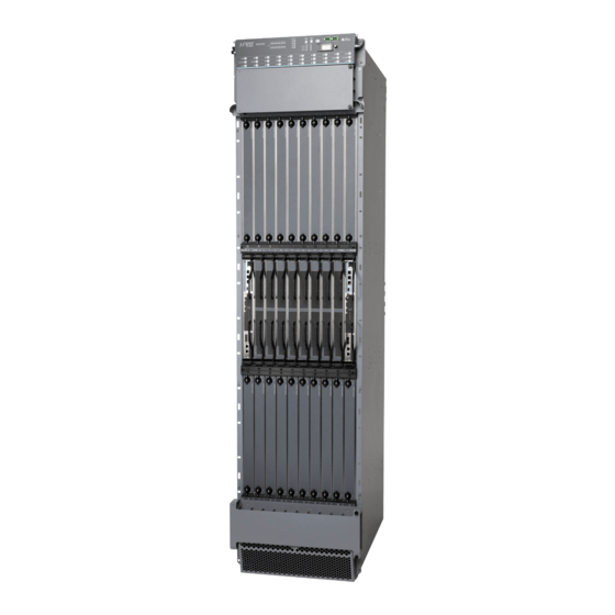
Page 38: Figure 1: Front View Of A Fully Configured Mx2020 Router Chassis
Figure 1: Front View of a Fully Configured MX2020 Router Chassis M X2 ONLI OFFL Remove field replacement units (FRUs) from the front of the MX2020 router before you install the router. See Table 3 on page 6 for information on MX2020 router components. -
Page 39: System Overview And Architecture
Chapter 2: System Overview and Architecture Table 3: Front Components in a Fully Configured MX2020 Router (continued) Component Component No. Description Slots Number of FRUs Switch Fabric Boards 0 through 7 (SFBs) Middle card cage air – filter Control Board and... -
Page 40: Figure 2: Rear View Of A Fully Configured Ac-Powered Mx2020 Router
MX2020 3D Universal Edge Router Hardware Guide Figure 2: Rear View of a Fully Configured AC-Powered MX2020 Router Chassis Remove field replacement units (FRUs) from the rear of the MX2020 router before you install the router. See Table 4 on page 8 for information on MX2020 router components. -
Page 41: Figure 3: Rear View Of A Fully Configured Dc-Powered Mx2020 Router
Fan tray air filter – Lower fan trays (two) Fan tray 0 and fan tray 1 (behind access door) Figure 3: Rear View of a Fully Configured DC-Powered MX2020 Router Chassis Copyright © 2015, Juniper Networks, Inc. -
Page 42: Table 5: Rear Components In A Fully Configured Dc-Powered Mx2020
MX2020 3D Universal Edge Router Hardware Guide Remove field replacement units (FRUs) from the rear of the MX2020 router before you install the router. See Table 5 on page 10 for information on MX2020 router components. Table 5: Rear Components in a Fully Configured DC-Powered MX2020... -
Page 43: Mx2020 Backplane Description
Related MX2020 Physical Specifications on page 108 Documentation Installing the MX2020 Mounting Hardware for a Four-Post Rack or Cabinet on page 205 MX2020 Router Grounding Specifications on page 117 MX2020 Chassis Moving Guidelines on page 107 MX2020 Backplane Description Backplanes are located toward the rear of the chassis and form the rear of the card cage. -
Page 44: Mx2020 Component Redundancy
If the master host subsystem (or either of its components) fails, the backup can take over as the master. DC power subsystem—The MX2020 DC power system is made up of two subsystems. Each subsystem provides power to ten line card slots, one local fan tray and critical FRUs. -
Page 45: Figure 5: Power Distribution From Each Power Subsystem To The Frus
0 fan tray 1 DC power feed redundancy—The MX2020 router subsystem is feed redundant. Each PSM can be connected to two separate feeds from different sources that are used to provide feed redundancy. There are two PDMs per power subsystem that carry nine feeds each. -
Page 46: Figure 7: Power Distribution From Three-Phase Feed Delta Pdm To The Ac
MX2020 3D Universal Edge Router Hardware Guide and three-phase wye. The AC power going to the PSMs is split into three individual phases—each PSM works on a single phase. This means the power system works independent of the kind of AC feed is connected. The user can connect one or two feeds, depending on the power system configuration (number of PSMs, redundancy, etc.). -
Page 47: Table 6: Ac Pdm Delta And Wye Current Requirements
60 A or 80 A current limit. The capacity of these feeds is relayed to system software through a switch located on the DC PDM. The MX2020 router supports two types of three-phase power system PDMs. The three-phase delta and three-phase wye. -
Page 48: Mx2020 Field-Replaceable Units
Displaying MX2020 Router Components and Serial Numbers Guidelines for Packing Router Components for Shipment on page 409 Returning a Hardware Component to Juniper Networks, Inc. on page 412 MX2020 Field-Replaceable Units Field-replaceable units (FRUs) are router components that can be replaced at the... -
Page 49: Mx2020 Router Hardware Components And Cli Terminology
Related Taking an MX2020 Host Subsystem Offline on page 401 Documentation Tools and Parts Required for Replacing MX2020 Hardware Components on page 416 Replacing the MX2020 Cable Managers on page 437 Replacing the MX2020 Craft Interface on page 450 Replacing an MX2020 Fan Tray on page 471... - Page 50 MX2020 3D Universal Edge Router Hardware Guide Table 8: MX2020 Router Hardware Components and CLI Terminology (continued) Component Hardware Model Number CLI Name Description AC Optimized Power MX2020-PREMIUM2-AC Chassis DC Optimized Power MX2020-PREMIUM2-DC Chassis Craft interface panel MX2020-CRAFT “MX2020 Craft Interface Front Panel Display Description”...
- Page 51 Chapter 2: System Overview and Architecture Table 8: MX2020 Router Hardware Components and CLI Terminology (continued) Component Hardware Model Number CLI Name Description PSM blank cover MX2000-PSM-BLANK “MX2020 Power Subsystem Description” on page 83 Power supply module MX2000-PSM-AC AC 52V Power Supply...
- Page 52 MX2020 3D Universal Edge Router Hardware Guide Copyright © 2015, Juniper Networks, Inc.
-
Page 53: Chassis Components And Descriptions
There must be a minimum of 45-U of usable rack space when installing the MX2020 router into a 45-U rack. NOTE: If you are installing the MX2020 router into a network cabinet, make sure that no hardware, device, rack, or cabinet component obstructs the 45-U rack space from access during installation. -
Page 54: Figure 9: Front View Of A Fully Configured Mx2020 Router Chassis
Figure 9: Front View of a Fully Configured MX2020 Router Chassis M X2 ONLI OFFL Remove field replacement units (FRUs) from the front of the MX2020 router before you install the router. See Table 3 on page 6 for information on MX2020 router components. -
Page 55: Chassis Components And Descriptions
Chapter 3: Chassis Components and Descriptions Table 9: Front Components in a Fully Configured MX2020 Router (continued) Component Component No. Description Slots Number of FRUs Switch Fabric Boards 0 through 7 (SFBs) Middle card cage air – filter Control Board and... -
Page 56: Figure 10: Rear View Of A Fully Configured Ac-Powered Mx2020 Router
MX2020 3D Universal Edge Router Hardware Guide Figure 10: Rear View of a Fully Configured AC-Powered MX2020 Router Chassis Remove field replacement units (FRUs) from the rear of the MX2020 router before you install the router. See Table 4 on page 8 for information on MX2020 router components. -
Page 57: Figure 11: Rear View Of A Fully Configured Dc-Powered Mx2020 Router Chassis
Fan tray air filter – Lower fan trays (two) Fan tray 0 and fan tray 1 (behind access door) Figure 11: Rear View of a Fully Configured DC-Powered MX2020 Router Chassis Copyright © 2015, Juniper Networks, Inc. -
Page 58: Table 11: Rear Components In A Fully Configured Dc-Powered Mx2020
MX2020 3D Universal Edge Router Hardware Guide Remove field replacement units (FRUs) from the rear of the MX2020 router before you install the router. See Table 5 on page 10 for information on MX2020 router components. Table 11: Rear Components in a Fully Configured DC-Powered MX2020... -
Page 59: Mx2020 Backplane Description
Related MX2020 Physical Specifications on page 108 Documentation Installing the MX2020 Mounting Hardware for a Four-Post Rack or Cabinet on page 205 MX2020 Router Grounding Specifications on page 117 MX2020 Chassis Moving Guidelines on page 107 MX2020 Backplane Description Backplanes are located toward the rear of the chassis and form the rear of the card cage. -
Page 60: Mx2020 Component Redundancy
If the master host subsystem (or either of its components) fails, the backup can take over as the master. DC power subsystem—The MX2020 DC power system is made up of two subsystems. Each subsystem provides power to ten line card slots, one local fan tray and critical FRUs. -
Page 61: Figure 13: Power Distribution From Each Power Subsystem To The Frus
0 fan tray 1 DC power feed redundancy—The MX2020 router subsystem is feed redundant. Each PSM can be connected to two separate feeds from different sources that are used to provide feed redundancy. There are two PDMs per power subsystem that carry nine feeds each. -
Page 62: Figure 16: Power Distribution From Three-Phase Feed Wye Pdm To The Ac
MX2020 3D Universal Edge Router Hardware Guide and three-phase wye. The AC power going to the PSMs is split into three individual phases—each PSM works on a single phase. This means the power system works independent of the kind of AC feed is connected. The user can connect one or two feeds, depending on the power system configuration (number of PSMs, redundancy, etc.). -
Page 63: Table 12: Ac Pdm Delta And Wye Current Requirements
60 A or 80 A current limit. The capacity of these feeds is relayed to system software through a switch located on the DC PDM. The MX2020 router supports two types of three-phase power system PDMs. The three-phase delta and three-phase wye. -
Page 64: Mx2020 Field-Replaceable Units
Displaying MX2020 Router Components and Serial Numbers Guidelines for Packing Router Components for Shipment on page 409 Returning a Hardware Component to Juniper Networks, Inc. on page 412 MX2020 Field-Replaceable Units Field-replaceable units (FRUs) are router components that can be replaced at the... -
Page 65: Mx2020 Router Hardware Components And Cli Terminology
Related Taking an MX2020 Host Subsystem Offline on page 401 Documentation Tools and Parts Required for Replacing MX2020 Hardware Components on page 416 Replacing the MX2020 Cable Managers on page 437 Replacing the MX2020 Craft Interface on page 450 Replacing an MX2020 Fan Tray on page 471... - Page 66 MX2020 3D Universal Edge Router Hardware Guide Table 14: MX2020 Router Hardware Components and CLI Terminology (continued) Component Hardware Model Number CLI Name Description AC Optimized Power MX2020-PREMIUM2-AC Chassis DC Optimized Power MX2020-PREMIUM2-DC Chassis Craft interface panel MX2020-CRAFT “MX2020 Craft Interface Front Panel Display Description”...
- Page 67 Chapter 3: Chassis Components and Descriptions Table 14: MX2020 Router Hardware Components and CLI Terminology (continued) Component Hardware Model Number CLI Name Description PSM blank cover MX2000-PSM-BLANK “MX2020 Power Subsystem Description” on page 83 Power supply module MX2000-PSM-AC AC 52V Power Supply...
- Page 68 MX2020 3D Universal Edge Router Hardware Guide Copyright © 2015, Juniper Networks, Inc.
-
Page 69: Alarm And Display Components
MX2020 Craft Interface Description on page 37 MX2020 Component LEDs on the Craft Interface on page 39 MX2020 Alarm Relay Contacts on the Craft Interface on page 41 MX2020 Alarm LEDs and Alarm Cutoff/Lamp Test Button on page 42 MX2020 Craft Interface Description The craft interface allows the user to view status and troubleshooting information at a glance and to perform many system control functions. -
Page 70: Figure 18: Extended Craft Interface
MX2020 3D Universal Edge Router Hardware Guide Figure 18: Extended Craft Interface Table 15: Craft Interface LEDs, Buttons, and Connectors Function No. Label Description Status LEDs for PSMs through through Status LEDs for fan trays through FANTRAYS , and Two sets of status LEDs per host subsystem. There... -
Page 71: Mx2020 Component Leds On The Craft Interface
MX2020 Craft Interface Serial Number Label MX2020 Component LEDs on the Craft Interface MX2020 Host Subsystem LEDs and Buttons on the Craft Interface on page 39 MX2020 Power Supply Module LEDs on the Craft Interface on page 40 MX2020 Line Card LEDs and Buttons on the Craft Interface on page 40... -
Page 72: Mx2020 Power Supply Module Leds On The Craft Interface
There are twenty push buttons located next to each of the line cards on the craft interface. These buttons are used to place the line cards online or offline. When a line card is inserted into an ADC, and installed into the MX2020 router the online/offline buttons can turn both cards on or off. -
Page 73: Mx2020 Fan Tray Leds On The Craft Interface
MX2020 Craft Interface Description on page 37 Documentation MX2020 Alarm Relay Contacts on the Craft Interface on page 41 MX2020 Alarm Relay Contacts on the Craft Interface The craft interface has two alarm relay contacts for connecting the router to external alarm devices. -
Page 74: Mx2020 Alarm Leds And Alarm Cutoff/Lamp Test Button
Related Disconnecting the Alarm Relay Wires from the MX2020 Craft Interface on page 283 Documentation Connecting the Alarm Relay Wires to the MX2020 Craft Interface on page 282 MX2020 Alarm LEDs and Alarm Cutoff/Lamp Test Button Two large alarm LEDs are located at the upper right of the craft interface. -
Page 75: Table 22: Alarm Leds And Alarm Cutoff/Lamp Test Button
(for testing) when pressed and held. Related MX2020 Craft Interface Description on page 37 Documentation MX2020 Alarm Relay Contacts on the Craft Interface on page 41 MX2020 Router Overview on page 3 Copyright © 2015, Juniper Networks, Inc. - Page 76 MX2020 3D Universal Edge Router Hardware Guide Copyright © 2015, Juniper Networks, Inc.
-
Page 77: Cable And Rack Management
MX2020 Cable Manager Description on page 45 MX2020 Rack-Mounting Hardware on page 50 MX2020 Cable Manager Description The MX2020 consists of a standard or extended cable management system. Standard Cable Management System on page 45 Extended Cable Management System on page 48... -
Page 78: Figure 20: Mx2020 Standard Cable Managers
MX2020 3D Universal Edge Router Hardware Guide You can pull the DC cable manager up and outward to lock it into the maintenance position. Figure 20: MX2020 Standard Cable Managers Front top Front bottom Rear DC Cable (for DC PDM) -
Page 79: Figure 21: Upper And Lower Cable Management
You can use cable strips or other ties to gently secure the cables in the middle cable manager. To secure the cables in place, loop the tie through the cable anchor and secure the tie. To access the air filter, the cable manager needs to be opened. Copyright © 2015, Juniper Networks, Inc. -
Page 80: Extended Cable Management System
MX2020 3D Universal Edge Router Hardware Guide Figure 22: Middle Card-Cage Cable Manager Figure 23: Middle Card-Cage Air Filter Extended Cable Management System The extended cable management system consists of the following components: Extended upper cable manager—MX2000-CBL-TOP-XT-S Extended lower cable manager—MX2000-CBL-BTM-XT-S Extended DC cable manager—MX2020-DC-CBL-MGR-XT-S... -
Page 81: Figure 24: Mx2020 Extended Cable Managers
You can use cable strips or other ties to gently secure the cables in the upper and lower extended cable managers. To secure the cables in place, loop the tie through the cable anchor and secure the tie. Figure 24: MX2020 Extended Cable Managers Front upper Front lower Rear DC PDM Copyright ©... -
Page 82: Mx2020 Rack-Mounting Hardware
MX2020 3D Universal Edge Router Hardware Guide Figure 25: Upper and Lower Extended Cable Management Related Installing the MX2020 Upper Cable Manager on page 332 Documentation Installing the MX2020 Lower Cable Manager on page 314 Installing the MX2020 DC Cable Manager on page 303... - Page 83 Chapter 5: Cable and Rack Management Installing the MX2020 Mounting Hardware for a Four-Post Rack or Cabinet on page 205 Copyright © 2015, Juniper Networks, Inc.
- Page 84 MX2020 3D Universal Edge Router Hardware Guide Copyright © 2015, Juniper Networks, Inc.
-
Page 85: Cooling System
CHAPTER 6 Cooling System MX2020 Cooling System Description on page 53 MX2020 Fan Tray LED on page 56 MX2020 Cooling System Description The cooling system consists of the following components: Fan tray—MX2000-FANTRAY Lower Fan Tray Air filter—MX2020-FLTR-KIT-S Air baffle—MX2000-UPR-BAFFLE The cooling system components work together to keep all router components within the acceptable temperature range. -
Page 86: Figure 27: Airflow Through The Chassis
Card cage Lower fan trays The MX2020 router provides a two-stage front-to-back cooling system. Air is pushed into the bottom inlet and up through the lower fan tray, and exits through the opening between the backplanes in the center of the chassis. This cools the bottom MPCs, half of the SFBs and CB-REs. -
Page 87: Figure 28: Upper/Lower Fan Tray
Figure 29: Lower Fan Tray Air Filter The air baffle is an optional component that can be purchased from Juniper Networks. When installed over the upper fan tray access door, the air baffle dissipates exhausted air away from the router. -
Page 88: Mx2020 Fan Tray Led
MX2020 Cooling System Description on page 53 Documentation Maintaining the MX2020 Fan Trays on page 345 Troubleshooting the MX2020 Cooling System on page 534 MX2020 Component LEDs on the Craft Interface on page 39 Copyright © 2015, Juniper Networks, Inc. -
Page 89: Host Subsystem Components
MX2020 CB-RE Description on page 59 RE-MX2000-1800x4 CB-RE Description on page 61 MX2020 CB-RE LEDs on page 62 MX2020 Switch Fabric Board Description on page 64 MX2020 Switch Fabric Board LED on page 65 MX2020 Host Subsystem Description The host subsystem provides routing protocol processes, as well as software processes that control the router’s interface, the chassis components, system management, and... -
Page 90: Supported Cb-Re
MX2020 3D Universal Edge Router Hardware Guide Supported CB-RE The CB-RE is hot-pluggable. Some key attributes of the MX2020 CB-RE are: CB-RE into one FRU. Air diverter to isolate upper and lower cooling zones. The MX2020 router supports the following CB-RE: RE-MX2000-1800x4 supported for Junos OS Release 12.3R2 and later. -
Page 91: Mx2020 Cb-Re Description
Maintaining the MX2020 Host Subsystem on page 370 Taking an MX2020 Host Subsystem Offline on page 401 Effect of Taking the MX2020 Host Subsystem Offline on page 402 Removing an MX2020 CB-RE on page 419 RJ-45 Connector Pinouts for MX Series CB-RE Auxiliary and Console Ports on page 145... - Page 92 MX2020 3D Universal Edge Router Hardware Guide Table 24: Components on the RE-MX2000-1800x4 (continued) Function No. Label Description This port is used to configure the CONSOLE MX2020 router. MGMT This port is a dedicated management channel for device maintenance. It is...
-
Page 93: Re-Mx2000-1800X4 Cb-Re Description
) provide support for hardware diagnostics and JCS port testing. XGE-0 XGE-1 ports provide access to external timing distribution. ExtClk EEPROM—Stores the serial number of the CB-RE. Reset button—Reboots the Routing Engine on the CB-RE when pressed. Copyright © 2015, Juniper Networks, Inc. -
Page 94: Re-Mx2000-1800X4 Cb-Re Boot Sequence
MX2020 3D Universal Edge Router Hardware Guide Online/Offline button—Takes the Routing Engine on the CB-RE online or offline when pressed. LEDs—Provide status of the Routing Engine on the CB-RE. RE-MX2000-1800x4 CB-RE Boot Sequence The router is shipped with the Junos OS preinstalled on the CB-RE. There are three copies of software: One copy on a USB flash drive that can be inserted into the slot on the CB-RE faceplate. -
Page 95: Table 25: Cb-Re Leds
GPS external clocking interface has failed. – GPS external clocking interface is offline. Related MX2020 Host Subsystem Description on page 57 Documentation Maintaining the MX2020 Host Subsystem on page 370 Taking an MX2020 Host Subsystem Offline on page 401 Copyright © 2015, Juniper Networks, Inc. -
Page 96: Mx2020 Switch Fabric Board Description
Figure 31: SFB OK/FAI L SFB Slots The user can install up to eight SFBs in the MX2020 router. The SFBs install vertically into the front of the chassis in the slots labeled through . If any slots are empty, you must install a blank panel. -
Page 97: Mx2020 Switch Fabric Board Led
Related MX2020 Host Subsystem Description on page 57 Documentation MX2020 Switch Fabric Board LED on page 65 Replacing an MX2020 SFB on page 494 MX2020 Switch Fabric Board LED One bicolor LED on the SFB indicate the status of the SFB. The LED, labeled... - Page 98 MX2020 3D Universal Edge Router Hardware Guide Copyright © 2015, Juniper Networks, Inc.
-
Page 99: Interface Modules-Adcs, Mpcs, And Mics
MPCs attach to the ADCs which in turn attach to the backplane. Future MPCs for the MX2020 can be used without an ADC. The MX2020 router has 20 dedicated line card slots, which means a maximum of 20 ADCs can be installed. The dedicated slots are numbered... -
Page 100: Mx2020 Modular Port Concentrator Description
Each MPC is equipped with up to four Junos Trio chipsets, which perform control functions tailored to the MPC’s media type. The MX2020 router supports up to 20 MPCs. For power requirements, see “Calculating DC Power Requirements for MX2020 Routers” on page 180 “Calculating AC Power... -
Page 101: Mpc Components
Figure 33 on page 69 shows a typical MPC supported on the MX2020 router. Figure 34 on page 69 shows an MPC installed vertically in the MX2020 router. For more information about MPCs, see the MX Series Interface Module Reference... -
Page 102: Mx2020 Modular Port Concentrator Leds
Replacing an MX2020 MPC on page 485 MICs Supported by MX Series Routers on page 74 MPCs Supported by MX240, MX480, MX960, MX2010, and MX2020 Routers Table 27 on page 71 lists the MPCs and their first supported Junos OS release on MX240, MX480, MX960, MX2010, and MX2020 routers. - Page 103 Chapter 8: Interface Modules—ADCs, MPCs, and MICs Table 27: MPCs Supported by MX240, MX480, MX960, MX2010, and MX2020 Routers First Junos OS Release on First Junos OS First Junos OS MX240, Release on Release on MX480, and MX2010 MX2020 MPC Name...
-
Page 104: Routers
MX2020 3D Universal Edge Router Hardware Guide Table 27: MPCs Supported by MX240, MX480, MX960, MX2010, and MX2020 Routers (continued) First Junos OS Release on First Junos OS First Junos OS MX240, Release on Release on MX480, and MX2010 MX2020... -
Page 105: Mx2020 Mpc Terminology
Related MX2020 Modular Port Concentrator Description on page 68 Documentation MX2020 Component LEDs on the Craft Interface on page 39 Holding an MX2020 MPC on page 404 Troubleshooting the MX2020 MPCs on page 538 Replacing an MX2020 MPC on page 485... -
Page 106: Mics Supported By Mx Series Routers
MX480, MX960, MX2010, and MX2020 routers. Table 29 on page 76 lists the first supported Junos OS release for MICs on MX5, MX10, MX40, MX80, and MX104 routers. Table 28: MICs Supported by MX240, MX480, MX960, MX2010, and MX2020 Routers MX240, MX480, MX960... -
Page 107: Table 28: Mics Supported By Mx240, Mx480, Mx960, Mx2010, And Mx2020
Chapter 8: Interface Modules—ADCs, MPCs, and MICs Table 28: MICs Supported by MX240, MX480, MX960, MX2010, and MX2020 Routers (continued) MX240, MX480, MX960 MX2010 MX2020 MIC Name MIC Model Number Ports Routers Routers Routers Gigabit Ethernet MIC with SFP MIC-3D-20GE-SFP-E 13.3... -
Page 108: Table 29: Mics Supported By Mx5, Mx10, Mx40, Mx80, And Mx104 Routers
MX2020 3D Universal Edge Router Hardware Guide Table 28: MICs Supported by MX240, MX480, MX960, MX2010, and MX2020 Routers (continued) MX240, MX480, MX960 MX2010 MX2020 MIC Name MIC Model Number Ports Routers Routers Routers Channelized SONET/SDH MIC-3D-4CHOC3-2CHOC12 11.4 12.3 12.3... - Page 109 MIC with SFP (H) Tri-Rate Tri-Rate MIC MIC-3D-40GE-TX – 11.2R4 11.2R4 10.2 13.2R2 Services Multiservices MIC MS-MIC-16G 13.2 13.2 13.2 13.2 13.3R2 Rear Rear Rear Rear slot slot slot slot only. only. only. only. Copyright © 2015, Juniper Networks, Inc.
-
Page 110: Mx2020 Modular Interface Card Leds
MIC faceplate, see the “LEDs” section for each MIC in the MX Series Interface Module Reference Related MX2020 Modular Interface Card Description on page 73 Documentation Maintaining MX2020 MICs on page 374 Troubleshooting the MX2020 MICs on page 537 Replacing an MX2020 MIC on page 477... -
Page 111: Mx2020 Port And Interface Numbering
Ethernet interface so—SONET/SDH interface xe—10-Gigabit Ethernet interface For a complete list of media types, see Interface Naming Overview. fpc—Slot in which the MPC is installed. On the MX2020 router, the MPCs are represented in the CLI as through FPC 0 FPC 19 pic—Logical PIC on the MIC. -
Page 112: Figure 36: Mx2020 Interface Port Mapping
MX2020 3D Universal Edge Router Hardware Guide PIC 3 BUILTIN BUILTIN 10x 1GE(LAN) SFP Xcvr 0 REV 01 740-011613 P9F13CH SFP-SX Xcvr 1 REV 01 740-011782 PAR1L2E SFP-SX Xcvr 2 REV 01 740-011782 P9M0TLC SFP-SX Xcvr 3 REV 01 740-011613... - Page 113 Related MX2020 Router Hardware Components and CLI Terminology on page 17 Documentation Copyright © 2015, Juniper Networks, Inc.
- Page 114 MX2020 3D Universal Edge Router Hardware Guide Copyright © 2015, Juniper Networks, Inc.
-
Page 115: Power Subsystem
MX2020 DC Power Supply Module LEDs on page 98 MX2020 Power Subsystem Description The MX2020 router uses AC or DC power distribution modules (PDMs) and AC or DC power supply modules (PSMs). The MX2020 router is configurable with up to four AC or DC PDMs (two per subsystem), and up to eighteen AC or DC PSMs. - Page 116 (one feed has each phase going to two PSMs, and the other feed has each phase going to a single PSM). AC PDMs—The MX2020 supports connection of a three-phase AC power system. There are two types of three-phase power systems. The three-phase delta and three-phase wye.
-
Page 117: Mx2020 Power Midplane Description
MX2020 DC Power Requirements on page 171 MX2020 Power Midplane Description The MX2020 power subsystem consists of a power midplane (PMP). This midplane is used to connect power from the PDM feeds (AC or DC) to the input of the PSMs (AC or DC) as well as the output from the PSMs to the FRUs (MPCs, CB-REs, SFBs, and Fan Trays). -
Page 118: Mx2020 Three-Phase Delta Ac Power Distribution Module Description
If the PDM must be removed, both input power cables must be uninstalled and removed from the PDM before the PDM can be removed from the chassis. The MX2020 chassis is not sensitive to phase rotation sequence—either CW or CCW will operate correctly. -
Page 119: Figure 38: Three-Phase Delta Ac Power Distribution Module Connections
Related MX2020 Power Subsystem Description on page 83 Documentation Maintaining the MX2020 Power Supply Modules on page 386 Troubleshooting the MX2020 Power Subsystem on page 541 MX2020 AC Power Requirements on page 147 MX2020 AC Power Subsystem Electrical Specifications on page 158 MX2020 AC Power Cord Specifications on page 154 Copyright ©... -
Page 120: Mx2020 Three-Phase Wye Ac Power Distribution Module Description
If the PDM must be removed, both input power cables must be uninstalled and removed from the PDM before the PDM can be removed from the chassis. The MX2020 chassis is not sensitive to phase rotation sequence—either CW or CCW will operate correctly. -
Page 121: Figure 41: Three-Phase Wye Ac Power Distribution Module Connections
Related MX2020 Power Subsystem Description on page 83 Documentation Maintaining the MX2020 Power Supply Modules on page 386 Troubleshooting the MX2020 Power Subsystem on page 541 MX2020 AC Power Requirements on page 147 MX2020 AC Power Cord Specifications on page 154... -
Page 122: Description
Related MX2020 Power Subsystem Description on page 83 Documentation Maintaining the MX2020 Power Supply Modules on page 386 Troubleshooting the MX2020 Power Subsystem on page 541 MX2020 AC Power Requirements on page 147 MX2020 AC Power Subsystem Electrical Specifications on page 158... -
Page 123: Mx2020 Three-Phase Delta And Wye Ac Power Distribution Module Leds
DC Power Cable Specifications for the MX2010 Router Site Electrical Wiring Guidelines for MX Series Routers on page 592 MX2020 Three-Phase Delta and Wye AC Power Distribution Module LEDs Figure 45 on page 92 shows the LEDs on the three-phase delta AC PDM faceplate. The three-phase wye AC PDM has the same LEDs. -
Page 124: Mx2020 Nine-Feed Single Phase Ac Power Distribution Module Description
— The right AC terminal block is not receiving voltage. Related MX2020 Three-Phase Delta AC Power Distribution Module Description on page 86 Documentation MX2020 Three-Phase Wye AC Power Distribution Module Description on page 88 Maintaining the MX2020 Power Supply Modules on page 386... -
Page 125: Mx2020 Ac Power Supply Module Leds
Related MX2020 Power Subsystem Description on page 83 Documentation Maintaining the MX2020 Power Supply Modules on page 386 Troubleshooting the MX2020 Power Subsystem on page 541 MX2020 AC Power Requirements on page 147 MX2020 AC Power Subsystem Electrical Specifications on page 158... -
Page 126: Mx2020 Dc Power Distribution Module Description
(bottom to top). A minimum PDM0/Input0 PDM3/Input1 of one PDM is required per subsystem (two PDMs per MX2020 chassis) for nonredundant power. The DC PDMs provides power interface to nine PSMs. Four PDMs provide full redundancy. NOTE: Power backplane distributes regulated 52VDC to all boards supplied by that subsystem. -
Page 127: Mx2020 Dc Power Distribution Module Leds
MX2020 Router Grounding Specifications on page 117 Calculating DC Power Requirements for MX2020 Routers on page 180 DC Power Circuit Breaker Requirements for the MX2020 Router on page 184 MX2020 DC Power Distribution Description on page 177 DC Power Cable Specifications for the MX2020 Router on page 184... -
Page 128: Mx2020 Dc Power Supply Module Description
MX2020 DC Power Subsystem Electrical Specifications on page 179 MX2020 DC Power Supply Module Description The MX2020 supports a two zone DC power system. Each zone (upper and lower) is provided power by one half of the power subsystem. In the DC power configuration, the... -
Page 129: Figure 49: Dc Power Supply Module
Chapter 9: Power Subsystem NOTE: The MX2020 systems configured for DC input power must use only DC PDMs and DC PSMs. AC and DC PSMs or PDMs must not be mixed within a single system. Up to nine PSMs may be connected in parallel to increase available system power across MPCs as needed and provide redundancy. -
Page 130: Mx2020 Dc Power Supply Module Leds
MX2020 DC Power Supply Module LEDs on page 98 Documentation MX2020 Router Grounding Specifications on page 117 DC Power Circuit Breaker Requirements for the MX2020 Router on page 184 MX2020 DC Power Distribution Description on page 177 DC Power Cable Specifications for the MX2020 Router on page 184... -
Page 131: Table 35: Mx2020 Dc Power Supply Module Leds
DC input is detected but voltage is out of range. – DC input to the PSM is not present. Related MX2020 Component LEDs on the Craft Interface on page 39 Documentation MX2020 Power Subsystem Description on page 83 MX2020 DC Power Supply Module Description on page 96 MX2020 DC Power Subsystem Electrical Specifications on page 179 Copyright ©... - Page 132 MX2020 3D Universal Edge Router Hardware Guide Copyright © 2015, Juniper Networks, Inc.
-
Page 133: Site Planning, Preparation, And Specifications
Planning and Preparing the Site on page 103 Transceiver and Cable Specifications on page 127 Pinout Specifications on page 145 AC Power Requirements, Specifications, and Guidelines on page 147 DC Power Requirements, Specifications, and Guidelines on page 171 Copyright © 2015, Juniper Networks, Inc. - Page 134 MX2020 3D Universal Edge Router Hardware Guide Copyright © 2015, Juniper Networks, Inc.
-
Page 135: Planning And Preparing The Site
MX2020 Chassis Moving Guidelines on page 107 MX2020 Physical Specifications on page 108 MX2020 Rack Requirements on page 110 MX2020 Moving Requirements and Guidelines Using a Router Transport Kit on page 113 MX2020 Router Environmental Specifications on page 116 MX2020 Router Grounding Specifications on page 117... - Page 136 MX2020 DC Power Supply Module Description on page 96 MX2020 DC Power Requirements on page 171 DC Power Cable Specifications for the MX2020 Router on page 184 MX2020 DC Power Distribution Description on page 177 Plan rack location, including required space clearances. See:...
-
Page 137: Mx2020 Cabinet Airflow Requirements
Understanding Fiber-Optic Cable Signal Loss, Attenuation, and Dispersion on page 127 Plan the cable routing and management. See: MX2020 Cable Manager Description on page 45 Maintaining Cables That Connect to MX2020 MPCs or MICs on page 338 Related MX2020 Router Overview on page 3 Documentation... -
Page 138: Mx2020 Cabinet Size And Clearance Requirements
Card cage Airflow divider Card cage Lower fan trays Related Clearance Requirements for Airflow and Hardware Maintenance for the MX2020 Router Documentation on page 121 MX2020 Cabinet Size and Clearance Requirements on page 106 MX2020 Rack Requirements on page 110... -
Page 139: Mx2020 Chassis Moving Guidelines
(91.95 cm) between the inside of the front door and the inside of the rear door. NOTE: If you are installing the MX2020 router into a network cabinet, make sure that no hardware, device, rack, or cabinet component obstructs the 45-U rack space from access during installation. -
Page 140: Mx2020 Physical Specifications
MX2020 3D Universal Edge Router Hardware Guide MX2020 Physical Specifications Table 36 on page 108 Table 37 on page 108 summarize the physical specifications for the router chassis and the components. Table 36: MX2020 Shipping Weight Specifications Item Shipping Weight Shipping crate and pallet 527 lb (239.04 kg) - Page 141 28.16 in. (71.52 cm) 2.62 in. (6.65 cm) Fully populated with 4 total: 100 lb (45.35 kg) Standard cable 6.8 lb (3.08 kg) 18.99 in. (48.23 cm) 2.80 in. (7.11 cm) 8.226 in. 20.89 cm) manager (top) Copyright © 2015, Juniper Networks, Inc.
-
Page 142: Mx2020 Rack Requirements
Spacing of Mounting Bracket Holes on page 112 Connection to the Building Structure on page 113 Rack Size and Strength The MX2020 router is designed for installation in a rack that complies with either the following standards: Copyright © 2015, Juniper Networks, Inc. - Page 143 Juniper Networks does not supply this hardware, but consideration for the size and weight of the chassis is important for a safe installation.
-
Page 144: Spacing Of Mounting Bracket Holes
MX2020 3D Universal Edge Router Hardware Guide NOTE: For a complete list of chassis and component weights and measurements, see “MX2020 Physical Specifications” on page 108. NOTE: There must be a minimum of 45-U of usable rack space when installing the MX2020 router into a 45-U rack. -
Page 145: Connection To The Building Structure
Router Transport Kit Turning Radius on page 113 Router Transport Kit Requirements on page 114 Router Transport Kit Turning Radius The MX2020 requires a minimum 42 in. (106.7 cm) diameter of space to turn the chassis on the router transport kit (see Figure 53 on page 114. -
Page 146: Router Transport Kit Requirements
(106.7 cm) The weight of the router transport kit is 138.5 lb (63 kg). The maximum recommended height the MX2020 should be lifted from the floor using the router transport kit is 1.5 in. (3.8 cm). Router Transport Kit Requirements The side view measurements of the MX2020 router with the router transport kit installed is: 78.75 in. -
Page 147: Figure 54: Measurements Of The Router Transport Kit Installed On The Mx2020
23.40 in (59.4 cm) 36.20 in (91.95 cm) The front view measurements of the MX2020 router with the router transport kit installed is: 30.78 in. (78.2 cm), 19 in. (48.3 cm) wide (see Figure 55 on page 116). Copyright © 2015, Juniper Networks, Inc. -
Page 148: Mx2020 Router Environmental Specifications
19.0 in (48.26 cm) 30.78 in (78.2 cm) Related Clearance Requirements for Airflow and Hardware Maintenance for the MX2020 Router Documentation on page 121 MX2020 Rack-Mounting Hardware on page 50 MX2020 Cabinet Size and Clearance Requirements on page 106 MX2020 Cabinet Airflow Requirements on page 105... -
Page 149: Mx2020 Router Grounding Specifications
Articles 110-16, 110-17, and 110-18 of the National Electrical Code, ANSI/NFPA 70. Related Tools and Parts Required to Maintain the MX2020 Hardware Components on page 193 Documentation Definition of Safety Warning Levels on page 553... -
Page 150: Mx2020 Router Grounding Cable Lug Specifications
This separate protective earth terminal must be permanently connected to earth. NOTE: The MX2020 supports 4-AWG DC power cable lugs for 80-A input (see Figure 57 on page 119), and 6-AWG DC power cable lugs for 60-A input... -
Page 151: Mx2020 Router Grounding Cable Specifications
), used with 60-A PDM. Minimum 90°C wire, or as required by the local code MX2020 Router Grounding Cable Specifications The 48 VDC facility must be equipped with a circuit breaker rated 60 A (–48 VDC), or 80 A (–48 VDC) for each PDM input, and the grounding cable must be minimum 10 AWG, or as required by the local code. -
Page 152: Mx2020 Site Preparation Checklist
Related Grounding the MX2020 Router on page 247 Documentation Tools and Parts Required for Connecting the MX2020 Router to Power on page 192 MX2020 AC Power Electrical Safety Guidelines on page 584 MX2020 Site Preparation Checklist The checklist in... -
Page 153: Clearance Requirements For Airflow And Hardware Maintenance For The Mx2020
Installing an MX2020 Router Overview on page 189 Documentation Unpacking the MX2020 Router on page 195 Clearance Requirements for Airflow and Hardware Maintenance for the MX2020 Router When planning the installation site, you need to allow sufficient clearance around the rack (see... -
Page 154: Figure 59: Chassis Dimensions And Clearance Requirements For The Mx2020 Router With The Standard Cable Manager
MX2020 Power Distribution Modules (PDMs), and Power Supply Modules (PSMs); they are within specification. An MX2020 router with an extended cable manager requires extra clearance to accommodate the depth of 40.15 in. (102 cm). Figure 59: Chassis Dimensions and Clearance Requirements for the MX2020 Router with the Standard Cable Manager 36"... -
Page 155: Rack-Mounting Requirements
MX2020 Rack Requirements on page 110 Documentation MX2020 Rack-Mounting Hardware on page 50 MX2020 Cabinet Size and Clearance Requirements on page 106 MX2020 Cabinet Airflow Requirements on page 105 Rack-Mounting Requirements You can install the router in a four-post rack or cabinet. - Page 156 The cabinet must be clear of any hardware, device, rack, or cabinet component that obstructs the 45 U rack space from being access during installation. NOTE: There must be a minimum of 45-U of usable rack space when installing the MX2020 router into a 45-U rack. Copyright © 2015, Juniper Networks, Inc.
-
Page 157: Figure 61: Typical Four-Post Rack
Chapter 10: Planning and Preparing the Site Figure 61: Typical Four-Post Rack 84 in (213.4 cm) 19 in (48.3 cm) 24 in (61cm) to 30 in (76.2 cm) Copyright © 2015, Juniper Networks, Inc. - Page 158 MX2020 3D Universal Edge Router Hardware Guide Copyright © 2015, Juniper Networks, Inc.
-
Page 159: Transceiver And Cable Specifications
Calculating Power Budget and Power Margin for Fiber-Optic Cables on page 128 CB-RE Interface Cable and Wire Specifications for MX Series Routers on page 130 Installing an MX2020 Three-Phase Wye AC Power Cord on page 131 Network Cable and Transceiver Overview for ACX Series, M Series, and MX Series... -
Page 160: Attenuation And Dispersion In Fiber-Optic Cable
MX2020 3D Universal Edge Router Hardware Guide single-mode fiber. Compared with multimode fiber, single-mode fiber has higher bandwidth and can carry signals for longer distances. Exceeding the maximum transmission distances can result in significant signal loss, which causes unreliable transmission. -
Page 161: Calculating Power Budget For Fiber-Optic Cable
Table 42: Estimated Values for Factors Causing Link Loss Link-Loss Factor Estimated Link-Loss Value Higher-order mode losses Single-mode—None Multimode—0.5 dB Modal and chromatic dispersion Single-mode—None Multimode—None, if product of bandwidth and distance is less than 500 MHz-km Copyright © 2015, Juniper Networks, Inc. -
Page 162: Cb-Re Interface Cable And Wire Specifications For Mx Series Routers
MX2020 3D Universal Edge Router Hardware Guide Table 42: Estimated Values for Factors Causing Link Loss (continued) Link-Loss Factor Estimated Link-Loss Value Connector 0.5 dB Splice 0.5 dB Fiber attenuation Single-mode—0.5 dB/km Multimode—1 dB/km The following sample calculation for a 2-km-long multimode link with a power budget... -
Page 163: Installing An Mx2020 Three-Phase Wye Ac Power Cord
Removing an MX2020 CB-RE on page 419 Installing an MX2020 CB-RE on page 301 Installing an MX2020 Three-Phase Wye AC Power Cord To install a three-phase wye AC power cord: Switch off the customer site circuit breakers to the PDM being removed. Make sure that the voltage across the AC power source cord is 0 V and that there is no chance that the cord might become active during the installation process. -
Page 164: Figure 62: Connecting Power To A Three-Phase Wye Ac Power Distribution
MX2020 3D Universal Edge Router Hardware Guide Put the wires of the AC power cord through the hole of the retaining nut and rubber grommet. Put the wires of the AC power cord through the hole of the metal wiring compartment. -
Page 165: Table 44: Supported Three-Phase Wye Ac Wire Gauge
Chapter 11: Transceiver and Cable Specifications NOTE: The color of each AC power wire might vary. The MX2020 chassis is not sensitive to phase rotation sequence—either CW or CCW will operate correctly. CAUTION: Wire label configuration is for Juniper Networks supplied cable only. -
Page 166: Network Cable And Transceiver Overview For Acx Series, M Series, And Mx Series Routers
Network Cable and Transceiver Overview for ACX Series, M Series, and MX Series Routers Juniper Networks devices support a variety of fixed and pluggable transceivers and network cable, including multimode and single-mode fiber-optic cable. For a list of Copyright © 2015, Juniper Networks, Inc. -
Page 167: Supported Network Interface Standards By Transceiver For Acx, M, Mx, And T
Some transceivers support monitoring by using the operational mode CLI command show interfaces diagnostics optics . To determine which transceivers support monitoring, refer to the “Monitoring Available” column in Table 45 on page 136 Table 46 on page 141. Copyright © 2015, Juniper Networks, Inc. -
Page 168: Table 45: Supported Ethernet Standards
CAUTION: If you are having a problem running a Juniper Networks device that is using a third-party optic or cable, the Juniper Networks Technical Assistance Center (JTAC) can help you diagnose the source of the problem. Your JTAC engineer might recommend that you check the third-party optic or cable and potentially replace it with an equivalent Juniper Networks optic or cable that is qualified for the device. - Page 169 Interface Specifications SFP-GE40KM 1000BASE-EX Gigabit Ethernet 1000BASE Optical Interface Specifications SFP-GE40KT13R15 1000BASE-BX Fast Ethernet and Gigabit Ethernet Bidirectional SFP Optical Interface Specifications SFP-GE40KT15R13 1000BASE-BX Fast Ethernet and Gigabit Ethernet Bidirectional SFP Optical Interface Specifications Copyright © 2015, Juniper Networks, Inc.
- Page 170 MX2020 3D Universal Edge Router Hardware Guide Table 45: Supported Ethernet Standards (continued) Transceiver Monitoring Model Number Type Connector Available Standard Specifications SFP-GE80KCW1470-ET Gigabit Ethernet SFP CWDM Optical Interface Specifications SFP-GE80KCW1490-ET Gigabit Ethernet SFP CWDM Optical Interface Specifications SFP-GE80KCW1510-ET Gigabit Ethernet SFP...
- Page 171 XENPAK 10GBASE-SR 10-Gigabit Ethernet 10GBASE Optical Interface Specifications XENPAK-1XGE-ZR XENPAK 10GBASE-Z 10-Gigabit Ethernet 10GBASE Optical EOL (see Interface Specifications PSN-2010-02-649 XFP-10G-CBAND-T50-ZR 10GBASE-Z 10-Gigabit Ethernet 10GBASE Optical 10-Gigabit Ethernet Interface Specifications dense wavelength-division multiplexing (DWDM) Copyright © 2015, Juniper Networks, Inc.
- Page 172 MX2020 3D Universal Edge Router Hardware Guide Table 45: Supported Ethernet Standards (continued) Transceiver Monitoring Model Number Type Connector Available Standard Specifications XFP-10G-E-OC192-IR2 10GBASE-E 10-Gigabit Ethernet 10GBASE Optical Interface Specifications XFP-10G-L-OC192-SR1 10GBASE-L 10-Gigabit Ethernet 10GBASE Optical Interface Specifications XFP-10G-S 10GBASE-S...
-
Page 173: Table 46: Supported Sonet Standards
SONET OC3/STM1 Specifications SFP-OC3-IR SONET/SDH OC3/STM1 SONET/SDH OC3/STM1 Intermediate Reach Optical Interface Specifications SFP-OC3-LR SONET/SDH OC3/STM1 SONET/SDH OC3/STM1 Long Reach Optical Interface Specifications SFP-OC3-SR SONET/SDH OC3/STM1 SONET/SDH OC3/STM1 Multimode Optical Interface Specifications SONET OC12/STM4 Specifications Copyright © 2015, Juniper Networks, Inc. - Page 174 MX2020 3D Universal Edge Router Hardware Guide Table 46: Supported SONET Standards (continued) Transceiver Monitoring Model Number Type Connector Available Standard Specifications SFP-OC12-IR SONET/SDH SONET/SDH OC12/STM4 OC12/STM4 Optical Interface Intermediate Reach Specifications (IR-1) SFP-OC12-LR SONET/SDH SONET/SDH OC12/STM4 OC12/STM4 Long Reach...
- Page 175 Chapter 11: Transceiver and Cable Specifications Related Supported Network Interface Standards by Transceiver for PTX Series Routers Documentation Copyright © 2015, Juniper Networks, Inc.
- Page 176 MX2020 3D Universal Edge Router Hardware Guide Copyright © 2015, Juniper Networks, Inc.
-
Page 177: Pinout Specifications
DSR/DCD Data Set Ready Clear to Send Related MX2020 Host Subsystem Description on page 57 Documentation Removing an MX2020 CB-RE on page 419 Installing an MX2020 CB-RE on page 301 CB-RE Interface Cable and Wire Specifications for MX Series Routers on page 130... -
Page 178: Rj-45 Connector Pinouts For An Mx Series Cb-Re Management Port
MX2020 3D Universal Edge Router Hardware Guide RJ-45 Connector Pinouts for an MX Series CB-RE Management Port The port on the Control Board and Routing Engine (CB-RE) labeled is an MGMT autosensing 10/100-Mbps Ethernet RJ-45 receptacle that accepts an Ethernet cable for connecting the Routing Engine to a management LAN (or other device that supports out-of-band management). -
Page 179: Ac Power Requirements, Specifications, And Guidelines
MX2020 AC Power Supply Module Description on page 158 MX2020 Router Grounding Specifications on page 161 MX2020 Three-Phase Delta AC Power Distribution Module Specifications on page 163 MX2020 Three-Phase Wye AC Power Distribution Module Specifications on page 163 MX2020 Seven-Feed AC Power Distribution Module Specifications on page 164... -
Page 180: Table 49: Base Ac Power Requirements
MICs) includes seven SFBs, one host 2142 W (Typical) subsystem (Control Board and Routing Engine CB-RE), four fan trays, and craft interface, eight PSMs, and two PDMs Table 50: Typical AC Power Requirements for MX2020 Router Power Requirement (Watts) Component Model Number with 91% Efficiency... - Page 181 Chapter 13: AC Power Requirements, Specifications, and Guidelines Table 51: MX2020 FRU AC Power Requirements (continued) Maximum Power Component Model Number Requirement Fan trays, upper MX2000-FANTRAY 200 W (Typical) 1700 W at 55° C 1150 W at 40° C 350 W at 25° C...
- Page 182 MX2020 3D Universal Edge Router Hardware Guide Table 51: MX2020 FRU AC Power Requirements (continued) Maximum Power Component Model Number Requirement MPC2 MX-MPC2-3D 274 W MX-MPC2E-3D With MICs and optics: 348 W at 55° C 329 W at 40° C 315 W at 25°...
- Page 183 Chapter 13: AC Power Requirements, Specifications, and Guidelines Table 51: MX2020 FRU AC Power Requirements (continued) Maximum Power Component Model Number Requirement 2x100GE + 8x10GE MPC4E MPC4E-3D-2CGE-8XGE 610 W With optics: 610 W at 55° C, with SFPP ZR and CFP LR4 optics 550 W at 40°...
- Page 184 MX2020 3D Universal Edge Router Hardware Guide Table 51: MX2020 FRU AC Power Requirements (continued) Maximum Power Component Model Number Requirement 10-Gigabit Ethernet MIC MIC6-10G 74 W with SFP+ With optics: 53 W at 55° C, 40° C and 25° C with 10G BASE-SR and 10G BASE-LR optics 66 W at 55°...
- Page 185 Chapter 13: AC Power Requirements, Specifications, and Guidelines Table 51: MX2020 FRU AC Power Requirements (continued) Maximum Power Component Model Number Requirement 100-Gigabit Ethernet MIC MIC6-100G-CXP 57 W with CXP 49 W at 55° C with CXP SR10 optics 49 W at 40° C with CXP SR10 optics 49 W at 25°...
-
Page 186: Mx2020 Ac Power Cord Specifications
An AC power cord connects each PDM to the power distribution panel. For more information on AC PDM input power mapping, see “Mapping Input Power from AC Power Distribution Modules to AC Power Supply Modules on the MX2020 Router” on page 168. -
Page 187: Figure 63: Three-Phase Delta Ac Power Cord
Power Cable, China CBL-PWR-C21S-EU AC Power Cable, Europe CBL-PWR-C21S-INTL AC Power Cable, International CBL-PWR-C21S-IT AC Power Cable, Italy CBL-PWR-C21S-JP AC Power Cable, Japan CBL-PWR-C21S-US AC Power Cable, US/Canada Figure 63: Three-Phase Delta AC Power Cord Copyright © 2015, Juniper Networks, Inc. -
Page 188: Figure 64: Three-Phase Wye Ac Power Cord
MX2020 3D Universal Edge Router Hardware Guide Figure 64: Three-Phase Wye AC Power Cord Table 54 on page 156 provides specifications for the three-phase delta and wye AC power cord mating connectors. Figure 65 on page 157 Figure 66 on page 157 depict the mating connectors for the three-phase AC power cord. -
Page 189: Figure 65: Three-Phase Delta Ac Power Cord Mating Connector
Power cords and cable must not block access to device components or drape where people could trip on them. Related Connecting AC Power to an MX2020 Router with Three-Phase Delta AC Power Documentation Distribution Modules on page 249 Copyright © 2015, Juniper Networks, Inc. -
Page 190: Mx2020 Ac Power Subsystem Electrical Specifications
MX2020 AC Power Electrical Safety Guidelines on page 584 MX2020 AC Power Supply Module Description The MX2020 supports a three-phase AC power system. There are two types of three-phase power systems that can be installed in the router—three-phase delta or... -
Page 191: Figure 67: Ac Power Supply Module
, and SFBs in slot through NOTE: The MX2020 systems configured for three-phase wye AC input power must use only three-phase wye AC PDMs and AC PSMs. The systems configured for three-phase delta AC input power must use three-phase delta AC PDMs and AC PSMs. -
Page 192: Figure 68: Selecting Input Feed On The Ac Power Supply Module
NONE INP0 INP1 BOTH Related MX2020 AC Power Supply Module LEDs on page 93 Documentation MX2020 AC Power Cord Specifications on page 154 Installing the MX2020 Air Filter on page 296 Removing the MX2020 Air Filter on page 431 Copyright © 2015, Juniper Networks, Inc. -
Page 193: Mx2020 Router Grounding Specifications
(see Figure 56 on page 118). Figure 69: Connecting Chassis Grounding Points on the MX2020 Router MX2020 Router Grounding Cable Lug Specifications CAUTION: Before router installation begins, a licensed electrician must attach a cable lug to the grounding and power cables that you supply. -
Page 194: Mx2020 Router Grounding Cable Specifications
MX2020 3D Universal Edge Router Hardware Guide NOTE: The MX2020 supports 4-AWG DC power cable lugs for 80-A input (see Figure 57 on page 119), and 6-AWG DC power cable lugs for 60-A input (see Figure 58 on page 119). -
Page 195: Mx2020 Three-Phase Delta Ac Power Distribution Module Specifications
Related Grounding the MX2020 Router on page 247 Documentation Tools and Parts Required for Connecting the MX2020 Router to Power on page 192 MX2020 AC Power Electrical Safety Guidelines on page 584 MX2020 Three-Phase Delta AC Power Distribution Module Specifications Table 58 on page 163 lists the three-phase delta AC PDM electrical specifications. -
Page 196: Mx2020 Seven-Feed Ac Power Distribution Module Specifications
Related MX2020 Three-Phase Wye AC Power Distribution Module Description on page 88 Documentation Connecting AC Power to an MX2020 Router with Three-Phase Wye AC Power Distribution Modules on page 252 MX2020 AC Power Subsystem Electrical Specifications on page 158 MX2020 AC Power Cord Specifications on page 154... -
Page 197: Calculating Ac Power Requirements For Mx2020 Routers
AC input current rating 14 A @ 200 VAC Calculating AC Power Requirements for MX2020 Routers The information in this topic helps you determine which of the two input ratings for the PSM is suitable for various configurations. You determine suitability by subtracting the total power draw from the maximum output of the PSM. -
Page 198: Figure 72: Ac Pdm Three-Phase Delta Input Power
MX2020 3D Universal Edge Router Hardware Guide Table 62: Calculating AC Power Budget Power Maximum Maximum Power Supply Distribution Typical Input Input Power Output Power Module Module Power per PSM per PSM per PSM Efficiency Three-phase 2142 W 2800 W... -
Page 199: Figure 73: Ac Pdm Three-Phase Wye Input Power
Nominal value of line current is 14 A. Current rating for input #2 is 14 A. Calculate thermal output (BTUs). Multiply the input power requirement (in watts) by 3.41 as shown in Table 63 on page 168. Copyright © 2015, Juniper Networks, Inc. -
Page 200: Mapping Input Power From Ac Power Distribution Modules To Ac Power Supply Modules On The Mx2020 Router
MX2020 Power Subsystem Description on page 83 Documentation MX2020 AC Power Requirements on page 147 Connecting AC Power to an MX2020 Router with Three-Phase Delta AC Power Distribution Modules on page 249 Connecting AC Power to an MX2020 Router with Three-Phase Wye AC Power... -
Page 201: Figure 74: Mapping Ac Power Distribution Modules Input To Ac Power Supply
Table 64: Input AC Power Mapping for PDM0 and PDM1 PDM0/Input0 PDM0/Input0 (Left) (Right) PDM1/Input1 (Left) PDM1/Input1 (Right) PSM0 PSM3 PSM0 PSM6 PSM1 PSM4 PSM1 PSM7 PSM2 PSM5 PSM2 PSM8 – PSM6 PSM3 – – PSM7 PSM4 – – PSM8 PSM5 – Copyright © 2015, Juniper Networks, Inc. -
Page 202: Table 65: Input Ac Power Mapping For Pdm2 And Pdm3
Related MX2020 Three-Phase Wye AC Power Distribution Module Description on page 88 Documentation Connecting AC Power to an MX2020 Router with Three-Phase Wye AC Power Distribution Modules on page 252 Powering On the AC-Powered MX2020 Router on page 260 MX2020 AC Power Subsystem Electrical Specifications on page 158... -
Page 203: Dc Power Requirements, Specifications, And Guidelines
MX2020 DC Power Subsystem Electrical Specifications on page 179 Calculating DC Power Requirements for MX2020 Routers on page 180 DC Power Circuit Breaker Requirements for the MX2020 Router on page 184 DC Power Cable Specifications for the MX2020 Router on page 184... -
Page 204: Table 66: Fru Dc Power Requirements
MX2020 3D Universal Edge Router Hardware Guide Table 66: FRU DC Power Requirements Maximum Power Component Model Number Requirement Switch Fabric Boards (SFBs) MX2000-SFB 200 W (Typical) 220 W at 55° C 220 W at 40° C 220 W at 25° C... - Page 205 With MICs and optics: 520 W at 55° C, two 40 W MICs 420 W at 40° C, two CFP MICs with LR4 optics 408 W at 25° C, two CFP MICs with LR4 optics Copyright © 2015, Juniper Networks, Inc.
- Page 206 MX2020 3D Universal Edge Router Hardware Guide Table 66: FRU DC Power Requirements (continued) Maximum Power Component Model Number Requirement 32x10GE MPC4E MPC4E-3D-32XGE-SFPP 610 W With optics: 610 W at 55° C, with SFPP ZR optics 560 W at 40° C, with SFPP ZR optics 550 W at 25°...
- Page 207 CFP2 With optics: 94 W at 55° C with 100G BASE-LR4 OTN optics 86 W at 40° C with 100G BASE-LR4 OTN optics 74 W at 25° C with 100G BASE-LR4 OTN optics Copyright © 2015, Juniper Networks, Inc.
- Page 208 MX2020 3D Universal Edge Router Hardware Guide Table 66: FRU DC Power Requirements (continued) Maximum Power Component Model Number Requirement 100-Gigabit Ethernet MIC MIC6-100G-CXP 57 W with CXP 49 W at 55° C with CXP SR10 optics 49 W at 40° C with CXP SR10 optics 49 W at 25°...
-
Page 209: Mx2020 Dc Power Distribution Description
Related MX2020 Power Subsystem Description on page 83 Documentation Connecting Power to a DC-Powered MX2020 Router with Power Distribution Modules on page 262 MX2020 DC Power Subsystem Electrical Specifications on page 179 MX2020 DC Power Distribution Description on page 177... -
Page 210: Figure 75: Typical Dc Source Cabling To The Router
For field-wiring connections, use copper conductors only. CAUTION: Power cords and cables must not block access to device components or drape where people could trip on them. Related MX2020 DC Power Distribution Module Description on page 94 Documentation Copyright © 2015, Juniper Networks, Inc. -
Page 211: Mx2020 Dc Power Subsystem Electrical Specifications
Chapter 14: DC Power Requirements, Specifications, and Guidelines MX2020 DC Power Supply Module Description on page 96 Connecting Power to a DC-Powered MX2020 Router with Power Distribution Modules on page 262 Installing MX2020 DC Power Supply Modules on page 265... -
Page 212: Calculating Dc Power Requirements For Mx2020 Routers
MX2020 3D Universal Edge Router Hardware Guide MX2020 DC Power Distribution Module Description on page 94 MX2020 DC Power Supply Module Description on page 96 MX2020 DC Power Electrical Safety Guidelines on page 585 Calculating DC Power Requirements for MX2020 Routers The information in this topic helps you determine which PSMs are suitable for various configurations, as well as which PSMs are not suitable because output power is exceeded. -
Page 213: Table 68: Mx2020 Dc Power Zoning
Chapter 14: DC Power Requirements, Specifications, and Guidelines The MX2020 DC power subsystem is made up of two sub zones where each sub zone provides power to half of the FRUs in the chassis (see Table 68 on page 181 for information on power zoning). -
Page 214: Table 69: Typical Dc Power Requirements For Mx2020 Router
SFB—slots 0 through 7 MX2000-SFB 220 W * 8 = 1760 W MX2020 DC power subsystem (upper and lower half of chassis, 2100 W * 8 PSMs=16,800 W 60 A feeds to each PDM input) (+ 1 PSM@2100 W redundant... -
Page 215: Table 70: Calculating Dc Power Budget
Related MX2020 Power Subsystem Description on page 83 Documentation Overview of Preparing the Site for the MX2020 Router on page 103 MX2020 DC Power Distribution Description on page 177 MX2020 DC Power Subsystem Electrical Specifications on page 179 Copyright © 2015, Juniper Networks, Inc. -
Page 216: Dc Power Circuit Breaker Requirements For The Mx2020 Router
The cable lugs attach to the terminal studs of each PDM (see Figure 76 on page 185 Figure 77 on page 185). NOTE: The MX2020 supports 4-AWG DC power cable lugs for 80-A input, and 6-AWG DC power cable lugs for 60-A input. Copyright © 2015, Juniper Networks, Inc. -
Page 217: Figure 76: 4-Awg Dc Power Cable Lug
), used with 80-A PDM. Minimum 90°C wire, or as required by the local code Power Eighteen pairs of 6-AWG (13.3 mm ), used with 60-A PDM. Minimum 90°C wire, or as required by the local code Copyright © 2015, Juniper Networks, Inc. - Page 218 MX2020 DC Power Distribution Module Description on page 94 MX2020 DC Power Electrical Safety Guidelines on page 585 MX2020 DC Power Distribution Description on page 177 Connecting an MX2020 DC Power Distribution Module Cable on page 268 Copyright © 2015, Juniper Networks, Inc.
-
Page 219: Initial Installation And Configuration
Installing the Mounting Hardware on page 205 Installing the Router on page 209 Connecting the Router to Power on page 247 Connecting the Router to the Network on page 275 Initially Configuring the Router on page 287 Copyright © 2015, Juniper Networks, Inc. - Page 220 MX2020 3D Universal Edge Router Hardware Guide Copyright © 2015, Juniper Networks, Inc.
-
Page 221: Installation Overview
Tools Required to Install the MX2020 Router Using a Pallet Jack on page 191 Tools Required to Install the MX2020 Router Using a Router Transport Kit on page 191 Tools and Parts Required for Connecting the MX2020 Router to Power on page 192... -
Page 222: Tools And Parts Required To Unpack The Mx2020 Router
MX2020 3D Universal Edge Router Hardware Guide Installing a MX2020 Router Using a Router Transport Kit Overview on page 224 Ground the router. See: See: “Grounding the MX2020 Router” on page 247 Reinstall all components. See: Reinstalling Components in the MX2020 Chassis After Installing It In a Rack on page 236 Connect cables to the network and external devices. -
Page 223: Tools Required To Install The Mx2020 Router Using A Pallet Jack
Installing the MX2020 Router Using a Pallet Jack with Attachment on page 220 Reinstalling Components in the MX2020 Chassis After Installing It In a Rack on page 236 Tools Required to Install the MX2020 Router Using a Router Transport Kit... -
Page 224: Tools And Parts Required For Connecting The Mx2020 Router To Power
209 Installing the MX2020 Router Using a Router Transport Kit on page 229 Reinstalling Components in the MX2020 Chassis After Installing It In a Rack on page 236 Tools and Parts Required for Connecting the MX2020 Router to Power... -
Page 225: Tools And Parts Required To Maintain The Mx2020 Hardware Components
Wire cutters Electrostatic discharge (ESD) grounding wrist strap Related Connecting the MX2020 Router to a Network for Out-of-Band Management on page 275 Documentation Connecting the MX2020 Router to a Console or Auxiliary Device on page 276 Connecting an MX2020 Router to an External Alarm-Reporting Device on page 277... - Page 226 MX2020 3D Universal Edge Router Hardware Guide Copyright © 2015, Juniper Networks, Inc.
-
Page 227: Unpacking The Router
Overview of Unpacking the MX2020 Router To unpack the router: Gather the tools required to unpack the router. See: “Tools and Parts Required to Unpack the MX2020 Router” on page 190 Unpack the router. See: “Unpacking the MX2020 Router” on page 195 Unpack the router transport kit, if ordered. -
Page 228: Figure 78: Mx2020 Shipping Crate Dimensions
Depending on your configuration, the MX2020 may be shipped with additional components already installed. NOTE: The MX2020 can be ordered with extended EMI covers and extended cable managers. The shipping container measures 85.0 in. (215.9 cm) high, 42.0 in. (106.7 cm) wide, and 48.0 in. - Page 229 If you ordered a router transport kit, the shipping crate door is used as a ramp to guide the MX2020 out of the crate. Using a two person team, slide the remainder of the shipping crate off the pallet (see Figure 79 on page 198).
-
Page 230: Figure 79: Unpacking The Mx2020
Save the shipping crate cover, pallet, and packing materials in case you need to move or ship the router at a later time. Related Tools and Parts Required to Unpack the MX2020 Router on page 190 Documentation Verifying the MX2020 Parts Received on page 199... -
Page 231: Verifying The Mx2020 Parts Received
Chapter 16: Unpacking the Router Installing the MX2020 Router Using a Pallet Jack with Attachment on page 220 Installing the MX2020 Router Using a Router Transport Kit on page 229 Verifying the MX2020 Parts Received A packing list is included in each shipment. Check the parts in the shipment against the items on the packing list. -
Page 232: Table 75: Accessory Box Parts List
MX2020 3D Universal Edge Router Hardware Guide Table 74: Parts List for a Fully Configured MX2020 Router (continued) Component Quantity Standard upper cable manager Middle cable manager and air filter Standard lower cable manager Standard DC cable manager Extended upper cable manager (optional) -
Page 233: Unpacking The Router Transport Kit
Ethernet cable, RJ-45/RJ-45, 4-pair stranded UTP, Category 5E, 15 feet long ESD wrist strap with cable Related Tools and Parts Required to Unpack the MX2020 Router on page 190 Documentation Unpacking the MX2020 Router on page 195 MX2020 Router Overview on page 3 Unpacking the Router Transport Kit The router transport kit is shipped in a wooden crate. -
Page 234: Figure 81: Open Router Transport Kit Shipping Crate
MX2020 3D Universal Edge Router Hardware Guide To unpack the router transport kit: Move the router transport kit shipping crate to an ESD-approved staging area, where you have enough room to remove the kit for assembly. Position the shipping crate with the arrows pointing up. -
Page 235: Figure 82: Router Transport Kit Shipping Crate Door
Save the shipping crate cover, pallet, and packing materials in case you need to move or ship the router transport kit at a later time. Related Tools and Parts Required to Unpack the MX2020 Router on page 190 Documentation Verifying the MX2020 Parts Received on page 199 Installing the MX2020 Router Using a Router Transport Kit on page 229 Copyright ©... - Page 236 MX2020 3D Universal Edge Router Hardware Guide Copyright © 2015, Juniper Networks, Inc.
-
Page 237: Installing The Mounting Hardware
CHAPTER 17 Installing the Mounting Hardware Installing the MX2020 Mounting Hardware for a Four-Post Rack or Cabinet on page 205 Installing the MX2020 Mounting Hardware for a Four-Post Rack or Cabinet Installing Cage Nuts, If Needed on page 205 Installing the Four-Post Mounting Shelf on page 207... -
Page 238: Table 77: Mounting Hole Locations For Installing A Mx2020 Chassis In A Four-Post Rack Or Cabinet
Shelf (continued) Hole Distance Above U Division 0.25 in. (0.6 cm) 0.14 U Table 77: Mounting Hole Locations for Installing a MX2020 Chassis in a Four-Post Rack or Cabinet Hole Distance Above U Division 63.88 in. (162.2 cm) 36.50 U 58.63 in. -
Page 239: Installing The Four-Post Mounting Shelf
NOTE: There must be a minimum of 45-U unobstructed front-to-back usable rack space when installing the MX2020 router into a four-post rack or cabinet. Partially insert screws into the open holes in the rear flanges of the four-post mounting shelf. -
Page 240: Figure 83: Installing The Mounting Hardware For A Four-Post Rack Or Cabinet
MX2020 3D Universal Edge Router Hardware Guide Figure 83: Installing the Mounting Hardware for a Four-Post Rack or Cabinet 24 in. (60.96 cm) Front to 30 in (76.2 cm) NOTE: The two rear flanges on the four-post mounting shelf are adjustable from 24 in. -
Page 241: Installing The Router
Installing the MX2020 Router Using a Router Transport Kit on page 229 Reinstalling Components in the MX2020 Chassis After Installing It In a Rack on page 236 Removing Components from the MX2020 Router Chassis Before Installing It In a Rack Before installing the router with a router transport kit, you must first remove shipping covers and components from the chassis. - Page 242 MX2020 3D Universal Edge Router Hardware Guide Removing the Power Distribution Modules Before Installing an MX2020 Router Remove the topmost PDM ( PDM3/Input1 ) first, and then work your way downward. To remove an AC or DC PDM (see Figure 84 on page 211 Figure 85 on page 211).
-
Page 243: Removing The Power Supply Modules Before Installing An Mx2020
MX2020 Router Figure 85: Removing a DC Power Distribution Module Before Installing the MX2020 Router Removing the Power Supply Modules Before Installing an MX2020 Router To remove the AC or DC PSMs (see Figure 86 on page 212 Figure 87 on page... -
Page 244: Figure 86: Removing A Ac Power Supply Module Before Installing The Mx2020
MX2020 3D Universal Edge Router Hardware Guide We recommend this precaution even though the PSMs are not connected to power sources. Loosen the two captive screws that secure the PSM to the chassis. While grasping the handle on the PSM faceplate with one hand, use your other hand to guide the PSM. -
Page 245: Removing The Fan Trays Before Installing An Mx2020 Router
Chapter 18: Installing the Router Figure 87: Removing a DC Power Supply Module Before Installing the MX2020 Router Removing the Fan Trays Before Installing an MX2020 Router To remove the upper and lower fan tray (see Figure 88 on page 214... -
Page 246: Removing The Sfbs Before Installing An Mx2020 Router
Do not stack fan trays on one another after you remove them. Figure 88: Removing Upper Fan Trays Figure 89: Removing Lower Fan Trays Removing the SFBs Before Installing an MX2020 Router To remove the SFBs (see Figure 90 on page 215): Place an electrostatic bag or antistatic mat on a flat, stable surface. -
Page 247: Figure 90: Removing An Sfb
Do not stack hardware components on one another after you remove them. Place each component on an antistatic mat resting on a stable, flat surface. Repeat the procedure for each SFB. Figure 90: Removing an SFB OK/FAIL Copyright © 2015, Juniper Networks, Inc. -
Page 248: Removing The Mpcs With Adapter Card Before Installing An Mx2020
Place each one individually in an electrostatic bag or on its own antistatic mat on a flat, stable surface. Removing the MPCs without an Adapter Card Before Installing an MX2020 Router To remove an MPC without an ADC (see Figure 91 on page 217): Have ready an antistatic mat for the MPC. -
Page 249: Removing The Cb-Res Before Installing The Mx2020 Router
Figure 91: Removing an MPC without the ADC Removing the CB-REs Before Installing the MX2020 Router To remove a CB-RE (see Figure 92 on page 218): Have ready an antistatic mat for the CB-RE. -
Page 250: Figure 92: Removing A Cb-Re
Documentation Overview of Preparing the Site for the MX2020 Router on page 103 Tools Required to Install the MX2020 Router Using a Router Transport Kit on page 191 Installing the MX2020 Router Using a Router Transport Kit on page 229 Reinstalling Components in the MX2020 Chassis After Installing It In a Rack on page 236 Copyright ©... -
Page 251: Installing A Mx2020 Router Using A Pallet Jack Overview
Chapter 18: Installing the Router Installing a MX2020 Router Using a Pallet Jack Overview Because of the MX2020 router’s size and weight—1,515 lb (687.19 kg) depending on the configuration—we strongly recommend that you install the router using a pallet jack with pallet jack attachment. -
Page 252: Installing The Mx2020 Router Using A Pallet Jack With Attachment
Overview of Preparing the Site for the MX2020 Router on page 103 Documentation Tools Required to Install the MX2020 Router Using a Pallet Jack on page 191 Installing the MX2020 Router Using a Pallet Jack with Attachment on page 220... -
Page 253: Figure 94: Loading The Mx2020 Router Onto The Pallet Jack
Chapter 18: Installing the Router Using a four-person team to load the router onto the pallet jack, make sure it rests securely on the pallet jack attachment platform. Figure 94: Loading the MX2020 Router onto the Pallet Jack M X2 ONLI... -
Page 254: Figure 95: Securing The Mx2020 To The Pallet Jack Attachment
There must be a minimum of 45 U of usable rack space when installing the MX2020 router into a 45-U rack. Figure 95: Securing the MX2020 to the Pallet Jack Attachment LINE Lower the pallet jack before moving the chassis. This will help distribute the weight evenly and reduce the risk of tilting or damage to the chassis. -
Page 255: Figure 96: Loading The Mx2020 Router Into The Rack
Chapter 18: Installing the Router NOTE: If you are installing the MX2020 router into a network cabinet, make sure that no hardware, device, rack, or cabinet component obstructs the 45-U rack space from access during installation. Using the pallet jack, lift the chassis approximately 0.25 in. (0.6 cm) above the surface of the mounting shelf, and position it as close as possible to the shelf. -
Page 256: Installing A Mx2020 Router Using A Router Transport Kit Overview
Removing Components from the MX2020 Router Chassis Before Installing It In a Rack on page 209 Reinstalling Components in the MX2020 Chassis After Installing It In a Rack on page 236 Installing a MX2020 Router Using a Router Transport Kit Overview Because of the MX2020 router’s size and weight—1,515 lb (687.19 kg) depending on the... -
Page 257: Figure 97: Preparing The Router Transport Kit For Installation
Figure 97: Preparing the Router Transport Kit for Installation Remove the four shipping brackets that secure the router to the shipping crate platform using a 9/16-in. (14 mm) socket wrench, and a number 2 Phillips screwdriver, and set them aside. Copyright © 2015, Juniper Networks, Inc. -
Page 258: Securing The Mx2020 Router To The Router Transport Platform
MAST OFFLI ONLIN Related Overview of Preparing the Site for the MX2020 Router on page 103 Documentation Installing the MX2020 Router Using a Router Transport Kit on page 229 Securing the MX2020 Router to the Router Transport Platform To secure the router to the router transport platform: Ensure that the rack is in its permanent location and is secured to the building. -
Page 259: Figure 99: Securing The Crate Door To The Shipping Crate Platform
OFFLI NOTE: An empty MX2020 weighs approximately 429.6 lb (194.86 kg). Using a two person team on either side of the chassis, turn the handles on the router transport 4-5 times until the chassis is raised approximately 1 in. (2.54 cm), making sure that the chassis is level. - Page 260 MX2020 3D Universal Edge Router Hardware Guide CAUTION: Do not raise the chassis above 1 in. (2.54 cm). This will ensure the router will not tilt when transporting, which can result in injury or damage to the router. Turn the four wheels on the router transport kit toward the rear of the chassis.
-
Page 261: Installing The Mx2020 Router Using A Router Transport Kit
Chapter 18: Installing the Router Figure 100: Securing the Router Transport Platform Installing the MX2020 Router Using a Router Transport Kit Because of the router's size and weight—up to 1,515 lb (687.19 kg) depending on the configuration—you must use either a pallet jack or router transport kit to install the router. -
Page 262: Figure 101: Installing Winch Strap Plate
To install the MX2020 using a router transport kit: Install the winch strap plate to the rear of the router using the four captive screws,... -
Page 263: Figure 102: Installing Winch Mount Bracket To Rack Rails
Adjust the height of the router by turning the handles clockwise until the router transport platform is aligned with the surface of the mounting shelf and slightly higher than the mounting shelf (see Figure 103 on page 232). Copyright © 2015, Juniper Networks, Inc. -
Page 264: Figure 103: Align The Mx2020 Router With Rack Mounting Shelf
(see Figure 103 on page 232). Figure 103: Align the MX2020 Router with Rack Mounting Shelf Unlock the four toggle latches that secure the router transport platform to the router transport mounting plates and wheel assembly. -
Page 265: Figure 104: Remove Router Transport Mounting Plate And Wheel Assembly
Figure 104 on page 233). Figure 104: Remove Router Transport Mounting Plate and Wheel Assembly Attach the winch strap to the winch strap plate at the rear of the router (see Figure 105 on page 234). Copyright © 2015, Juniper Networks, Inc. -
Page 266: Figure 105: Attaching Winch Strap To Winch Strap Plate
MX2020 3D Universal Edge Router Hardware Guide Figure 105: Attaching Winch Strap to Winch Strap Plate Attach a 1-1/8 in. (28.57 mm) socket drive wrench to the winch mechanism and turn clockwise to start pulling the chassis into the rack onto the mounting shelf until the front-mounting flanges contact the rack rails. -
Page 267: Figure 106: Pulling The Mx2020 Into The Rack
Chapter 18: Installing the Router Figure 106: Pulling the MX2020 into the Rack NOTE: A four-person team is needed to carefully guide the router into the rack while operating the winch. Copyright © 2015, Juniper Networks, Inc. -
Page 268: Reinstalling Components In The Mx2020 Chassis After Installing It In A Rack
Overview of Preparing the Site for the MX2020 Router on page 103 Documentation Tools Required to Install the MX2020 Router Using a Router Transport Kit on page 191 Installing the Router Transport Kit on the MX2020 Router on page 224... - Page 269 Chapter 18: Installing the Router Reinstalling the MPCs After Installing the MX2020 In a Rack on page 243 Reinstalling the CB-REs After Installing the MX2020 In a Rack on page 244 Reinstalling the Power Distribution Modules After Installing the MX2020 In a Rack...
-
Page 270: Figure 107: Reinstalling An Ac Power Distribution Module
MX2020 3D Universal Edge Router Hardware Guide Figure 107: Reinstalling an AC Power Distribution Module Figure 108: Reinstalling a DC Power Distribution Module NOTE: For the DC-powered router, make sure the switch is set to 60 A, or 80 A to match the DC circuit input feed. -
Page 271: Figure 109: Reinstalling An Ac Power Supply Module
Chapter 18: Installing the Router Reinstalling the Power Supply Modules After Installing the MX2020 In a Rack To reinstall the AC or DC PSMs, follow this procedure for each PSM (see Figure 109 on page 239 Figure 110 on page 240): which shows the installation of the AC or DC PSM. -
Page 272: Reinstalling The Fan Trays After Installing The Mx2020 In A Rack
MX2020 3D Universal Edge Router Hardware Guide Figure 110: Reinstalling a DC Power Supply Module Reinstalling the Fan Trays After Installing the MX2020 In a Rack To reinstall the upper or lower fan trays (see Figure 111 on page 241... -
Page 273: Reinstalling The Sfbs After Installing The Mx2020 In A Rack
Reinstall the remaining components into the router. Figure 111: Installing Upper Fan Trays Figure 112: Installing Lower Fan Trays Reinstalling the SFBs After Installing the MX2020 In a Rack To reinstall an SFB (see Figure 113 on page 242):... -
Page 274: Reinstalling The Adapter Card After Installing The Mx2020 In A Rack
If one of the SFBs fails, do not remove the failed SFB until you have a replacement or blank panel to install. Figure 113: Reinstalling an SFB OK/FAIL Reinstalling the Adapter Card After Installing the MX2020 In a Rack To reinstall an ADC (see Figure 114 on page 243): Attach an electrostatic discharge (ESD) grounding strap to your bare wrist, and connect the strap to one of the ESD points on the chassis. -
Page 275: Reinstalling The Mpcs After Installing The Mx2020 In A Rack
Grasp both ejector handles, and gently close them inward simultaneously until the ADC is fully seated. Figure 114: Reinstalling an ADC Reinstalling the MPCs After Installing the MX2020 In a Rack To reinstall an MPC (see Figure 115 on page... -
Page 276: Reinstalling The Cb-Res After Installing The Mx2020 In A Rack
Turn both knobs and rotate them simultaneously clockwise until the MPC is fully seated into the ADC. Figure 115: Reinstalling an MPC Reinstalling the CB-REs After Installing the MX2020 In a Rack To reinstall a CB-RE (see Figure 116 on page... -
Page 277: Figure 116: Reinstalling A Cb-Re
Overview of Preparing the Site for the MX2020 Router on page 103 Documentation Tools Required to Install the MX2020 Router Using a Pallet Jack on page 191 Removing Components from the MX2020 Router Chassis Before Installing It In a Rack... - Page 278 MX2020 3D Universal Edge Router Hardware Guide Copyright © 2015, Juniper Networks, Inc.
-
Page 279: Connecting The Router To Power
Connecting the Router to Power Grounding the MX2020 Router on page 247 Connecting AC Power to an MX2020 Router with Three-Phase Delta AC Power Distribution Modules on page 249 Connecting AC Power to an MX2020 Router with Three-Phase Wye AC Power... -
Page 280: Figure 117: Connecting The Grounding Cable
Documentation Preventing Electrostatic Discharge Damage to an MX2020 Router on page 558 Connecting AC Power to an MX2020 Router with Three-Phase Delta AC Power Distribution Modules on page 249 Connecting AC Power to an MX2020 Router with Three-Phase Wye AC Power... -
Page 281: Connecting Ac Power To An Mx2020 Router With Three-Phase Delta Ac Power Distribution Modules
Chapter 19: Connecting the Router to Power Connecting AC Power to an MX2020 Router with Three-Phase Delta AC Power Distribution Modules CAUTION: Do not mix AC and DC power modules within the same router. WARNING: Power connections must be performed by a licensed electrician only. -
Page 282: Figure 118: Connecting Power To A Three-Phase Delta Ac Power Distribution
The three-phase delta AC PDM terminal blocks will be flipped depending on which slot the PDM gets plugged into. NOTE: The color of each AC power wire might vary. The MX2020 chassis is not sensitive to phase rotation sequence—either CW or CCW will operate correctly. -
Page 283: Table 78: Supported Three-Phase Delta Ac Wire Gauge
Chapter 19: Connecting the Router to Power CAUTION: Wire label configuration is for Juniper Networks supplied cable only. If using your own cable, make sure you use the proper connections. To connect wires to the terminal block that serves three PSMs: a. -
Page 284: Connecting Ac Power To An Mx2020 Router With Three-Phase Wye Ac Power Distribution Modules
MX2020 Three-Phase Delta AC Power Distribution Module Description on page 86 Documentation MX2020 Three-Phase Delta and Wye AC Power Distribution Module LEDs on page 91 Powering On the AC-Powered MX2020 Router on page 260 MX2020 AC Power Subsystem Electrical Specifications on page 158... - Page 285 Insert the wire labeled into the input terminal labeled d. Insert the wire labeled into the input terminal labeled e. Insert the wire labeled into the input terminal labeled Copyright © 2015, Juniper Networks, Inc.
-
Page 286: Figure 119: Connecting Power To A Three-Phase Wye Ac Power Distribution
The three-phase wye AC PDM terminal blocks will be flipped depending on which slot the PDM gets plugged into. NOTE: The color of each AC power wire might vary. The MX2020 chassis is not sensitive to phase rotation sequence—either CW or CCW will operate correctly. -
Page 287: Table 79: Supported Three-Phase Wye Ac Wire Gauge
Repeat the procedure for the other three-phase wye AC PDMs. Related MX2020 Three-Phase Wye AC Power Distribution Module Description on page 88 Documentation MX2020 Three-Phase Delta and Wye AC Power Distribution Module LEDs on page 91 Copyright © 2015, Juniper Networks, Inc. -
Page 288: Mapping Input Power From Ac Power Distribution Modules To Ac Power Supply Modules On The Mx2020 Router
MX2020 AC Power Subsystem Electrical Specifications on page 158 MX2020 AC Power Cord Specifications on page 154 Preventing Electrostatic Discharge Damage to an MX2020 Router on page 558 Mapping Input Power from AC Power Distribution Modules to AC Power Supply Modules... -
Page 289: Figure 120: Mapping Ac Power Distribution Modules Input To Ac Power Supply
Table 80: Input AC Power Mapping for PDM0 and PDM1 PDM0/Input0 PDM0/Input0 (Left) (Right) PDM1/Input1 (Left) PDM1/Input1 (Right) PSM0 PSM3 PSM0 PSM6 PSM1 PSM4 PSM1 PSM7 PSM2 PSM5 PSM2 PSM8 – PSM6 PSM3 – – PSM7 PSM4 – – PSM8 PSM5 – Copyright © 2015, Juniper Networks, Inc. -
Page 290: Installing Mx2020 Ac Power Supply Modules
Related MX2020 Three-Phase Wye AC Power Distribution Module Description on page 88 Documentation Connecting AC Power to an MX2020 Router with Three-Phase Wye AC Power Distribution Modules on page 252 Powering On the AC-Powered MX2020 Router on page 260 MX2020 AC Power Subsystem Electrical Specifications on page 158... -
Page 291: Figure 121: Selecting Ac Power Subsystem Feed Redundancy
Figure 122 on page 259). Apply between 10 lb-in. (1.13 Nm) to 12 lb-in. (1.35 Nm) of torque to each screw. Do not overtighten the screws. Figure 122: MX2020 Router with AC Power Supply Modules Installed Copyright © 2015, Juniper Networks, Inc. -
Page 292: Powering On The Ac-Powered Mx2020 Router
Each PSM slot not occupied by a AC PSM must be covered by a PSM blank panel. Related Preventing Electrostatic Discharge Damage to an MX2020 Router on page 558 Documentation Powering On the AC-Powered MX2020 Router on page 260 Powering On the AC-Powered MX2020 Router You can use this procedure for a router with either a three-phase delta AC PDM or a three-phase wye AC PDM. - Page 293 Documentation MX2020 Three-Phase Wye AC Power Distribution Module Description on page 88 Connecting the MX2020 Router to a Console or Auxiliary Device on page 276 Connecting AC Power to an MX2020 Router with Three-Phase Delta AC Power Distribution Modules on page 249...
-
Page 294: Connecting Power To A Dc-Powered Mx2020 Router With Power Distribution
MX2020 3D Universal Edge Router Hardware Guide Replacing an MX2020 AC Power Supply Module on page 428 Replacing an MX2020 Three-Phase Delta AC Power Distribution Module on page 510 Connecting Power to a DC-Powered MX2020 Router with Power Distribution Modules... - Page 295 The nut should be able to spin freely with your fingers when it is first placed onto the terminal stud. Applying installation torque to the nut when the nut is improperly threaded may result in damage to the terminal stud. Copyright © 2015, Juniper Networks, Inc.
- Page 296 MX2020 3D Universal Edge Router Hardware Guide CAUTION: The maximum torque rating of the terminal studs on the DC PDM is 25 lb-in. (33.89 Nm). The terminal studs may be damaged if excessive torque is applied. Use only a torque-controlled driver or socket wrench to tighten nuts on the DC PDM terminal studs.
-
Page 297: Installing Mx2020 Dc Power Supply Modules
Grounding points (on chassis) Related DC Power Cable Specifications for the MX2020 Router on page 184 Documentation Preventing Electrostatic Discharge Damage to an MX2020 Router on page 558 Powering On the DC-Powered MX2020 Router on page 273 Installing MX2020 DC Power Supply Modules... -
Page 298: Figure 125: Selecting Dc Power Subsystem Feed Redundancy
Figure 126 on page 266). Apply between 10 lb-in. (1.13 Nm) to 12 lb-in. (1.35 Nm) of torque to each screw. Do not overtighten the screws. Figure 126: MX2020 Router with DC Power Supply Modules Installed Copyright © 2015, Juniper Networks, Inc. -
Page 299: Figure 127: Mx2020 Dc Power Supply Module Front View
Each PSM slot not occupied by a DC PSM must be covered by a PSM blank panel. Related Preventing Electrostatic Discharge Damage to an MX2020 Router on page 558 Documentation Powering On the DC-Powered MX2020 Router on page 273 Copyright © 2015, Juniper Networks, Inc. -
Page 300: Connecting An Mx2020 Dc Power Distribution Module Cable
MX2020 3D Universal Edge Router Hardware Guide Connecting an MX2020 DC Power Distribution Module Cable WARNING: Before performing DC power procedures, disconnect all power sources. To ensure that all power is , locate the circuit breaker on the panel board that services the DC circuit, switch the circuit breaker to the position, and tape the switch handle of the circuit breaker in the position. -
Page 301: Figure 128: Connecting Power Cables To The Dc Power Distribution Module
LEDs light green steadily. –48V Related Preventing Electrostatic Discharge Damage to an MX2020 Router on page 558 Documentation MX2020 DC Power Distribution Module Description on page 94 DC Power Cable Specifications for the MX2020 Router on page 184... -
Page 302: Connect Power To A Single-Phase Seven-Feed Ac Power Distribution
MX2020 3D Universal Edge Router Hardware Guide MX2020 DC Power Electrical Safety Guidelines on page 585 Connect Power to a Single-Phase Seven-Feed AC Power Distribution Module CAUTION: Do not mix AC and DC power modules within the same router. To connect an AC power cord to an seven-feed single-phase AC PDM: Attach an electrostatic discharge (ESD) grounding strap to your bare wrist, and connect the strap to an approved site ESD grounding point. -
Page 303: Connect Power To A Seven-Feed Dc Power Distribution Module
Table 67 on page 179 describes the DC operating range specifications. Attach the positive (+) DC source power cable lug to the (return) terminal. Attach the negative (–) DC source power cable lug to the (input) terminal. –48V Copyright © 2015, Juniper Networks, Inc. -
Page 304: Figure 129: Connecting Ground And Dc Power Cables
MX2020 3D Universal Edge Router Hardware Guide Table 82: MX2010 DC Power System Input Voltage Item Specification DC input voltage Operating range: –40 to –72 VDC Figure 129: Connecting Ground and DC Power Cables Cable Flat Terminal washer studs Split... -
Page 305: Powering On The Dc-Powered Mx2020 Router
Close the cable restraint cover over the terminal studs, and tighten the captive screws. Powering On the DC-Powered MX2020 Router To power on a DC-powered router:... - Page 306 Configuring the MX2020 Router” on page 287. Related Connecting the MX2020 Router to Management and Alarm Devices on page 275 Documentation Preventing Electrostatic Discharge Damage to an MX2020 Router on page 558 Replacing an MX2020 DC Power Supply Module on page 454 Replacing an MX2020 DC Power Distribution Module on page 457 Copyright ©...
-
Page 307: Connecting The Router To The Network
Connecting the Router to the Network Connecting the MX2020 Router to Management and Alarm Devices on page 275 Connecting the MX2020 Router to a Network for Out-of-Band Management on page 278 Connecting the MX2020 Router to a Console or Auxiliary Device on page 279... -
Page 308: Connecting The Mx2020 Router To A Console Or Auxiliary Device
It is also used for system administrators to monitor and manage the MX2020 remotely. Connecting the MX2020 Router to a Console or Auxiliary Device To use a system console to configure and manage the Routing Engine, connect it to the appropriate port on the CB-RE interface. -
Page 309: Connecting An Mx2020 Router To An External Alarm-Reporting Device
Chapter 20: Connecting the Router to the Network Figure 132: Console and Auxiliary Ports Figure 133: Console and Auxiliary Cable Connector Table 84: Console and Auxiliary Ports on the MX2020 CB-RE Function No. Label Description Connect a laptop, modem, or other auxiliary unit. -
Page 310: Connecting The Mx2020 Router To A Network For Out-Of-Band Management
Tools and Parts Required for MX2020 Router Connections on page 193 Documentation Connecting MPC or MIC Cables to the MX2020 Router on page 284 CB-RE Interface Cable and Wire Specifications for MX Series Routers on page 130 Connecting the MX2020 Router to a Network for Out-of-Band Management... -
Page 311: Connecting The Mx2020 Router To A Console Or Auxiliary Device
MX2020 remotely. Related Connecting the MX2020 Router to a Console or Auxiliary Device on page 276 Documentation Connecting an MX2020 Router to an External Alarm-Reporting Device on page 277 Connecting the MX2020 Router to a Console or Auxiliary Device... -
Page 312: Connecting An Mx2020 Router To An External Alarm-Reporting Device
CONSOLE to configure the MX2020 router. Related Connecting the MX2020 Router to a Network for Out-of-Band Management on page 275 Documentation Connecting an MX2020 Router to an External Alarm-Reporting Device on page 277 Connecting an MX2020 Router to an External Alarm-Reporting Device... -
Page 313: Figure 139: Alarm Relay Contacts
(NO) relays that signal a minor or major alarm when broken. Related Connecting the MX2020 Router to a Console or Auxiliary Device on page 276 Documentation Connecting the MX2020 Router to a Network for Out-of-Band Management on page 275 Copyright © 2015, Juniper Networks, Inc. -
Page 314: Connecting The Alarm Relay Wires To The Mx2020 Craft Interface
Related Installing the MX2020 Craft Interface on page 299 Documentation Removing the MX2020 Craft Interface on page 451 Maintaining and Verifying the Status of the MX2020 Craft Interface on page 399 Copyright © 2015, Juniper Networks, Inc. -
Page 315: Disconnecting The Alarm Relay Wires From The Mx2020 Craft Interface
Related Installing the MX2020 Craft Interface on page 299 Documentation Removing the MX2020 Craft Interface on page 451 Maintaining and Verifying the Status of the MX2020 Craft Interface on page 399 Copyright © 2015, Juniper Networks, Inc. -
Page 316: Connecting Mpc Or Mic Cables To The Mx2020 Router
MX2020 3D Universal Edge Router Hardware Guide Connecting MPC or MIC Cables to the MX2020 Router To connect the MPCs or MICs to the network (see Figure 142 on page 285 Figure 143 on page 285): Have ready a length of the type of cable used by the component. For cable... -
Page 317: Figure 142: Attaching A Cable To A Mpc
Figure 142: Attaching a Cable to a MPC Figure 143: Attaching a Cable to a MIC Related Connecting the MX2020 Router to Management and Alarm Devices on page 275 Documentation Tools and Parts Required for MX2020 Router Connections on page 193 Grounding the MX2020 Router on page 247 Copyright ©... - Page 318 MX2020 3D Universal Edge Router Hardware Guide Copyright © 2015, Juniper Networks, Inc.
-
Page 319: Initially Configuring The Router
The MX2020 router is shipped with the Junos OS preinstalled and ready to be configured when the MX2020 router is powered on. There are three copies of the software: one on a CompactFlash card in the CB-RE, one on a solid state drive (SSD) in the CB-RE, and... -
Page 320: Figure 144: Usb Flash Drive Port On Cb-Re
MX2020 3D Universal Edge Router Hardware Guide Figure 144: USB Flash Drive Port on CB-RE Gather the following information before configuring the router: Name the router will use on the network Domain name the router will use IP address and prefix length information for the Ethernet interface... - Page 321 SSH public key string (DSA or RSA). [edit] root@# set system root-authentication plain-text-password New password: password Retype new password: password [edit] root@# set system root-authentication encrypted-password encrypted-password [edit] root@# set system root-authentication ssh-dsa public-key Copyright © 2015, Juniper Networks, Inc.
- Page 322 MX2020 3D Universal Edge Router Hardware Guide [edit] root@# set system root-authentication ssh-rsa public-key (Optional) Configure the static routes to remote subnets with access to the management port. Access to the management port is limited to the local subnet. To access the management port from a remote subnet, you need to add a static route to that subnet within the routing table.
- Page 323 Powering On the AC-Powered MX2020 Router on page 260 Documentation Powering On the DC-Powered MX2020 Router on page 273 Grounding the MX2020 Router on page 247 Routine Maintenance Procedures for the MX2020 Router on page 407 Copyright © 2015, Juniper Networks, Inc.
- Page 324 MX2020 3D Universal Edge Router Hardware Guide Copyright © 2015, Juniper Networks, Inc.
-
Page 325: Installing And Replacing Components
Installing an MX2020 Three-Phase Wye AC Power Distribution Module on page 328 Installing the MX2020 Upper Cable Manager on page 332 Installing an SFP or XFP Transceiver into an MX2020 MPC or MIC on page 333 Installing an MX2020 AC Power Supply Module... - Page 326 MX2020 3D Universal Edge Router Hardware Guide WARNING: The AC PSMs have no circuit breakers that can physically disconnect AC current from the router. After AC feeds have been connected to the PDM, the AC voltage is always present on the power midplane and is distributed to the PSM connectors on the power midplane.
-
Page 327: Installing An Mx2020 Adapter Card
Chapter 22: Installing and Replacing Components Figure 145: Installing an AC Power Supply Module Related Preventing Electrostatic Discharge Damage to an MX2020 Router on page 558 Documentation MX2020 AC Power Supply Module Description on page 158 MX2020 AC Power Subsystem Electrical Specifications on page 158... -
Page 328: Installing The Mx2020 Air Filter
Figure 146: Installing an ADC Related MX2020 Adapter Card (ADC) Description on page 67 Documentation Maintaining the MX2020 Adapter Cards on page 338 Removing an MX2020 Adapter Card on page 489 Installing the MX2020 Air Filter To install the lower air filter—MX2020-FLTR-KIT-S:... -
Page 329: Figure 147: Installing The Air Filter
Figure 147: Installing the Air Filter To install the middle card cage cable manager air filter—MX2020-MID-FLTR-PNL-S: Attach an electrostatic discharge (ESD) grounding strap to your bare wrist, and connect the strap to one of the ESD points on the chassis. -
Page 330: Figure 148: Installing The Middle Card Cage Cable Manager Air Filter
Grasp the PSM air filter and insert into the chassis until it stops, (see Figure 149 on page 299). Tighten the two captive screws to secure. NOTE: The AC-powered MX2020 router has the same air filter. Copyright © 2015, Juniper Networks, Inc. -
Page 331: Installing The Mx2020 Craft Interface
Chapter 22: Installing and Replacing Components Figure 149: Installing the PSM Air Filter Related Maintaining the MX2020 Air Filter on page 341 Documentation Removing the MX2020 Air Filter on page 431 Installing the MX2020 Craft Interface To install the craft interface (see... -
Page 332: Installing An Mx2020 Extended Craft Interface
Related MX2020 Craft Interface Description on page 37 Documentation Maintaining and Verifying the Status of the MX2020 Craft Interface on page 399 Removing the MX2020 Craft Interface on page 451 Installing an MX2020 Extended Craft Interface To install the extended craft interface (see... -
Page 333: Installing An Mx2020 Cb-Re
Figure 151: Installing the Extended Craft Interface Related MX2020 Craft Interface Description on page 37 Documentation Maintaining and Verifying the Status of the MX2020 Craft Interface on page 399 Installing an MX2020 CB-RE To install a CB-RE (see Figure 152 on page... - Page 334 MX2020 3D Universal Edge Router Hardware Guide IntakeA-Zone0 Temperature 25 degrees C / 77 degrees F IntakeB-Zone1 Temperature 29 degrees C / 84 degrees F IntakeC-Zone0 Temperature 28 degrees C / 82 degrees F ExhaustA-Zone0 Temperature 26 degrees C / 78 degrees F...
-
Page 335: Installing The Mx2020 Dc Cable Manager
Chapter 22: Installing and Replacing Components Figure 152: Installing a CB-RE Related Preventing Electrostatic Discharge Damage to an MX2020 Router on page 558 Documentation Effect of Taking the MX2020 Host Subsystem Offline on page 402 Taking an MX2020 Host Subsystem Offline on page 401... -
Page 336: Figure 153: Installing The Standard Dc Cable Manager
DC PDM. Push down to secure the DC cable manager in place. Figure 153: Installing the Standard DC Cable Manager Related Removing the MX2020 DC Cable Manager on page 439 Documentation Copyright © 2015, Juniper Networks, Inc. -
Page 337: Installing An Mx2020 Dc Power Supply Module
Chapter 22: Installing and Replacing Components Installing an MX2020 DC Power Supply Module Before you install a PSM, be aware of the following: NOTE: The DC PSM is hot-swappable when a minimum number of PSMs installed and operational. WARNING: The DC PSMs have no circuit breakers that can physically disconnect DC current from the router. -
Page 338: Installing An Mx2020 Dual-Wide Mic
Related MX2020 DC Power Supply Module Description on page 96 Documentation Removing an MX2020 DC Power Supply Module on page 454 Installing an MX2020 Dual-Wide MIC To install a dual-wide MIC: Attach an electrostatic discharge (ESD) grounding strap to your bare wrist, and connect the strap to one of the ESD points on the chassis. -
Page 339: Figure 155: Removing The Septum
Chapter 22: Installing and Replacing Components Store the septum and screws for later use. Install the MPC as described in “Installing an MX2020 MPC into an Adapter Card” on page 492. Figure 155: Removing the Septum Remove four screws Remove two on bottom. -
Page 340: Installing The Mx2020 Standard Emi Covers
“Maintaining MX2020 MICs” on page 374. Related Preventing Electrostatic Discharge Damage to an MX2020 Router on page 558 Documentation Removing an MX2020 MIC on page 477 Installing an MX2020 MIC on page 315 Installing the MX2020 Standard EMI Covers... -
Page 341: Installing The Mx2020 Extended Emi Cover
Chapter 22: Installing and Replacing Components Figure 156: Installing the Standard EMI Card Cage Cover Related Removing the MX2020 Standard EMI Covers on page 465 Documentation Installing the MX2020 Extended EMI Cover Two extended electromagnetic interference (EMI) covers attach to the router over the upper and lower card cages. -
Page 342: Figure 157: Installing The Extended Emi Cover Mounting Brackets
MX2020 3D Universal Edge Router Hardware Guide Figure 157: Installing the Extended EMI Cover Mounting Brackets Orient the cover so that the arrows point up in front of the card cage. Angle the cover so that the points each side of the extended EMI cover fit into the grooves on the EMI cover mounting brackets. -
Page 343: Figure 158: Installing The Extended Emi Card Cage Cover
Chapter 22: Installing and Replacing Components Figure 158: Installing the Extended EMI Card Cage Cover Related Replacing the MX2020 Standard EMI Covers on page 465 Documentation Copyright © 2015, Juniper Networks, Inc. -
Page 344: Installing An Mx2020 Fan Tray
MX2020 3D Universal Edge Router Hardware Guide Installing an MX2020 Fan Tray This topic describes how to install the upper or lower fan trays in a MX2010. This procedure applies to both the standard fan tray and the optimized power fan tray.To install the... -
Page 345: Installing The Mx2020 Air Baffle
Figure 159: Installing Upper Fan Trays Figure 160: Installing Lower Fan Trays Related Preventing Electrostatic Discharge Damage to an MX2020 Router on page 558 Documentation Maintaining the MX2020 Fan Trays on page 345 Removing an MX2020 Fan Tray on page 472 Installing the MX2020 Air Baffle To install the air baffle—MX2000-UPR-BAFFLE:... -
Page 346: Installing The Mx2020 Lower Cable Manager
MX2020 3D Universal Edge Router Hardware Guide Figure 161: Installing the Air Baffle Related Maintaining the MX2020 Air Baffle on page 344 Documentation Removing the MX2020 Air Baffle on page 475 Installing the MX2020 Lower Cable Manager NOTE: To accommodate additional clearance, you may order an extended lower cable manager from Juniper Networks. -
Page 347: Installing An Mx2020 Mic
Place the MPC on a flat surface (if necessary, remove the MPC from the ADC as described in “Removing an MX2020 MPC from the Adapter Card” on page 487. Position the septum in the center of the MPC so that it lines up with holes labeled on the top of the MPC. -
Page 348: Figure 163: Installing The Septum
MX2020 3D Universal Edge Router Hardware Guide Figure 163: Installing the Septum Slide septum Install four screws into MPC. on bottom. Install two screws. If the MIC uses fiber-optic cable, verify that a rubber safety cap is over each transceiver on the faceplate. -
Page 349: Figure 164: Installing A Mic
“Maintaining MX2020 MICs” on page 374. Figure 164: Installing a MIC Related Preventing Electrostatic Discharge Damage to an MX2020 Router on page 558 Documentation Removing an MX2020 MIC on page 477 Installing an MX2020 Dual-Wide MIC on page 306 Copyright © 2015, Juniper Networks, Inc. -
Page 350: Installing An Mx2020 Sfb
MX2020 3D Universal Edge Router Hardware Guide Installing an MX2020 SFB To install an SFB (see Figure 165 on page 323): Attach an electrostatic discharge (ESD) grounding strap to your bare wrist, and connect the strap to one of the ESD points on the chassis. - Page 351 1032 mV LTC3880-XF1-1.5v-RAIL 1499 mV LTC3880-XF1-1.5v-CH0 1499 mV LTC3880-XF1-1.5v-CH1 1501 mV LTC3880-XF1-1.0v-RAIL 1029 mV LTC3880-XF1-1.0v-CH0 1029 mV LTC3880-XF1-1.0v-CH1 1032 mV LTC3880-XF0-1.5v-RAIL 1499 mV LTC3880-XF0-1.5v-CH0 1499 mV LTC3880-XF0-1.5v-CH1 1500 mV LTC3880-XF0-1.0v-RAIL 1029 mV LTC3880-XF0-1.0v-CH0 1029 mV Copyright © 2015, Juniper Networks, Inc.
- Page 352 MX2020 3D Universal Edge Router Hardware Guide LTC3880-XF0-1.0v-CH1 1032 mV LTC3880-3.3v-RAIL 3299 mV LTC3880-3.3v-CH0 3299 mV LTC3880-3.3v-CH1 3299 mV SFB 3 status: State Online Intake-Zone0 Temperature 44 degrees C / 111 degrees F Exhaust-Zone1 Temperature 40 degrees C / 104 degrees F...
- Page 353 Power LTC3880-XF2-1.5v-RAIL 1500 mV LTC3880-XF2-1.5v-CH0 1500 mV LTC3880-XF2-1.5v-CH1 1500 mV LTC3880-XF2-1.0v-RAIL 1029 mV LTC3880-XF2-1.0v-CH0 1029 mV LTC3880-XF2-1.0v-CH1 1032 mV LTC3880-XF1-1.5v-RAIL 1499 mV LTC3880-XF1-1.5v-CH0 1499 mV LTC3880-XF1-1.5v-CH1 1500 mV LTC3880-XF1-1.0v-RAIL 1029 mV LTC3880-XF1-1.0v-CH0 1029 mV Copyright © 2015, Juniper Networks, Inc.
- Page 354 MX2020 3D Universal Edge Router Hardware Guide LTC3880-XF1-1.0v-CH1 1033 mV LTC3880-XF0-1.5v-RAIL 1500 mV LTC3880-XF0-1.5v-CH0 1500 mV LTC3880-XF0-1.5v-CH1 1501 mV LTC3880-XF0-1.0v-RAIL 1029 mV LTC3880-XF0-1.0v-CH0 1029 mV LTC3880-XF0-1.0v-CH1 1033 mV LTC3880-3.3v-RAIL 3300 mV LTC3880-3.3v-CH0 3300 mV LTC3880-3.3v-CH1 3299 mV SFB 7 status:...
-
Page 355: Installing An Mx2020 Three-Phase Delta Ac Power Distribution Module
Maintaining the MX2020 SFB on page 397 Documentation Removing an MX2020 SFB on page 495 Installing an MX2020 Three-Phase Delta AC Power Distribution Module Before you install a three-phase delta AC PDM, be aware of the following: WARNING: Before performing AC power procedures, disconnect all power sources. - Page 356 MX2020 3D Universal Edge Router Hardware Guide NOTE: After powering off a PDM, wait at least 60 seconds before turning the circuit breaker back on. NOTE: The PDMs are hot swappable in a redundant configuration. However, you cannot switch from one type of PDU (AC or DC) to another while the system is on.
-
Page 357: Figure 166: Installing A Three-Phase Delta Ac Power Distribution Module
Insert the grounding wire into the grounding point labeled b. Insert the wire labeled into the input terminal labeled c. Insert the wire labeled into the input terminal labeled d. Insert the wire labeled into the input terminal labeled Copyright © 2015, Juniper Networks, Inc. -
Page 358: Figure 167: Connecting Power To A Three-Phase Delta Ac Power Distribution
The three-phase delta AC PDM terminal blocks will be flipped depending on which slot the PDM gets plugged into. NOTE: The color of each AC power wire may vary. The MX2020 chassis is not sensitive to phase rotation sequence—either CW or CCW will operate correctly. -
Page 359: Table 91: Supported Three-Phase Delta Ac Wire Gauge
Remove the ESD grounding strap from the ESD points on the chassis. Connect the strap to an approved site ESD grounding point. See the instructions for your site. Connect the AC power cord plug to the power source. Copyright © 2015, Juniper Networks, Inc. -
Page 360: Installing An Mx2020 Three-Phase Wye Ac Power Distribution Module
Documentation MX2020 Three-Phase Delta AC Power Distribution Module Specifications on page 163 Removing an MX2020 Three-Phase Delta AC Power Distribution Module on page 510 Installing an MX2020 Three-Phase Wye AC Power Distribution Module Each three-phase wye AC PDM weighs approximately 12 lb (5.44 kg). To install a... -
Page 361: Figure 168: Installing A Three-Phase Wye Ac Power Distribution Module
To insert wires into the terminal block that serves six PSMs: a. Insert the grounding wire into the grounding point labeled b. Insert the wire labeled into the input terminal labeled c. Insert the wire labeled into the input terminal labeled Copyright © 2015, Juniper Networks, Inc. -
Page 362: Figure 169: Connecting Power To A Three-Phase Wye Ac Power Distribution
The three-phase wye AC PDM terminal blocks will be flipped depending on which slot the PDM gets plugged into. NOTE: The color of each AC power wire might vary. The MX2020 chassis is not sensitive to phase rotation sequence—either CW or CCW will operate correctly. -
Page 363: Table 92: Supported Three-Phase Wye Ac Wire Gauge
Using a number 2 Phillips (+) screwdriver, tighten the four captive screws on the metal AC wiring compartment. Verify that the AC power cord is not touching or blocking access to router components, and that it does not drape where people could trip on it. Copyright © 2015, Juniper Networks, Inc. -
Page 364: Installing The Mx2020 Upper Cable Manager
MX2020 Three-Phase Wye AC Power Distribution Module Specifications on page 163 Documentation MX2020 Three-Phase Wye AC Power Distribution Module Description on page 88 Connecting AC Power to an MX2020 Router with Three-Phase Wye AC Power Distribution Modules on page 252 Installing the MX2020 Upper Cable Manager... -
Page 365: Installing An Sfp Or Xfp Transceiver Into An Mx2020 Mpc Or Mic
Removing the MX2020 Upper Cable Manager on page 438 Documentation Installing an SFP or XFP Transceiver into an MX2020 MPC or MIC To install an SFP or XFP: Attach an electrostatic discharge (ESD) grounding strap to your bare wrist, and connect the strap to one of the ESD points on the chassis. - Page 366 Verify that the status LEDs on the component faceplate indicate that the SFP or XFP is functioning correctly. For more information about the component LEDs, see the Series Interface Module Reference Related Removing an SFP or XFP Transceiver from an MX2020 MPC or MIC on page 502 Documentation Copyright © 2015, Juniper Networks, Inc.
-
Page 367: Maintaining The Chassis And Components
PART 4 Maintaining the Chassis and Components Maintaining Components on page 337 Packing and Returning Components on page 409 Replacing Components on page 415 Powering Off the Router on page 527 Copyright © 2015, Juniper Networks, Inc. - Page 368 MX2020 3D Universal Edge Router Hardware Guide Copyright © 2015, Juniper Networks, Inc.
-
Page 369: Maintaining Components
Maintaining the MX2020 Adapter Cards on page 338 Maintaining Cables That Connect to MX2020 MPCs or MICs on page 338 Maintaining and Verifying the Status of the MX2020 Router Components on page 340 Maintaining the MX2020 Air Filter on page 341... -
Page 370: Maintaining The Mx2020 Adapter Cards
Documentation Installing an MX2020 MPC into an Adapter Card on page 492 Connecting MPC or MIC Cables to the MX2020 Router on page 284 Installing a Cable on an MX2020 MPC or MIC on page 425 Maintaining Cables That Connect to MX2020 MPCs or MICs... -
Page 371: Figure 171: Upper And Lower Cable Manager Cable Routing
Figure 171: Upper and Lower Cable Manager Cable Routing NOTE: The MX2020 supports both standard and extended upper and lower cable management. Place excess cable out of the way in the upper and lower cable managers. Do not allow fastened loops of cable to dangle from the connector or cable manager because this stresses the cable at the fastening point. -
Page 372: Maintaining And Verifying The Status Of The Mx2020 Router Components
Opptex Cletop-S Fiber Cleaner. Follow the directions for the cleaning kit you use. Related Tools and Parts Required to Maintain the MX2020 Hardware Components on page 193 Documentation MX2020 Cable Manager Description on page 45 Maintaining MX2020 MPCs on page 375... -
Page 373: Maintaining The Mx2020 Air Filter
Maintaining the MX2020 SFB on page 397 Maintaining the MX2020 Switch Processor Mezzanine Board on page 398 Maintaining and Verifying the MX2020 Router Version on page 398 Maintaining and Verifying the Status of the MX2020 Craft Interface on page 399 Maintaining the MX2020 Air Filter Purpose For optimum cooling, verify the condition of the air filter. -
Page 374: Maintaining The Mx2020 Chassis Fru Power On Sequence
For optimum router performance, verify the condition of the FRU power on sequence. Action On a regular basis: Check the status of the MX2020 chassis FRU power on sequence issuing the command. show chassis power sequence The output displays the chassis FRU power on sequence: user@host>... -
Page 375: Maintaining The Mx2020 Cooling System Components
Maintaining the MX2020 Air Vents on page 344 Maintaining the MX2020 Air Filter on page 344 Maintaining the MX2020 Air Baffle on page 344 Maintaining the MX2020 Fan Trays on page 345 Maintaining the MX2020 Cooling System Zones on page 355 Copyright © 2015, Juniper Networks, Inc. -
Page 376: Maintaining The Mx2020 Air Vents
MX2020 3D Universal Edge Router Hardware Guide Maintaining the MX2020 Air Vents Purpose For optimum cooling, verify the condition of the air vents. Dust can clog air vents, reducing cooling system efficiency. Action On a regular basis, check the vents and clean them as necessary. -
Page 377: Maintaining The Mx2020 Fan Trays
Chapter 23: Maintaining Components Action On a regular basis, check the air baffle louvers are set to a 90-degree angle. Figure 172: Air Baffle Maintaining the MX2020 Fan Trays Purpose For optimum cooling, verify the condition of the fans. Action Monitor the status of the fans. - Page 378 MX2020 3D Universal Edge Router Hardware Guide CB 0 IntakeB-Zone1 29 degrees C / 84 degrees F CB 0 IntakeC-Zone0 28 degrees C / 82 degrees F CB 0 ExhaustA-Zone0 27 degrees C / 80 degrees F CB 0 ExhaustB-Zone1...
- Page 379 54 degrees C / 129 degrees F SFB 4 SFB-XF1-Zone0 46 degrees C / 114 degrees F SFB 4 SFB-XF0-Zone0 45 degrees C / 113 degrees F SFB 5 Intake-Zone0 33 degrees C / 91 degrees F Copyright © 2015, Juniper Networks, Inc.
- Page 380 NOTE: The fan numbers are stamped into the fan tray sheet metal next to each fan. For monitoring the temperature of specific items in the MX2020 router, the output for show chassis environment monitored command is similar to the following: user@host>...
- Page 381 FPC 4 LU 0 TSen 47 degrees C / 116 degrees F FPC 4 LU 0 Chip 46 degrees C / 114 degrees F FPC 4 LU 1 TSen 47 degrees C / 116 degrees F Copyright © 2015, Juniper Networks, Inc.
- Page 382 MX2020 3D Universal Edge Router Hardware Guide FPC 4 LU 1 Chip 48 degrees C / 118 degrees F FPC 4 LU 2 TSen 47 degrees C / 116 degrees F FPC 4 LU 2 Chip 37 degrees C / 98 degrees F...
- Page 383 Item Normal High Normal Bad fan Normal Bad fan Normal Routing Engine 0 Routing Engine 1 CB 0 IntakeA-Zone0 CB 0 IntakeB-Zone1 CB 0 IntakeC-Zone0 CB 0 ExhaustA-Zone0 CB 0 ExhaustB-Zone1 CB 0 TCBC-Zone0 Copyright © 2015, Juniper Networks, Inc.
- Page 384 MX2020 3D Universal Edge Router Hardware Guide CB 1 IntakeA-Zone0 CB 1 IntakeB-Zone1 CB 1 IntakeC-Zone0 CB 1 ExhaustA-Zone0 CB 1 ExhaustB-Zone1 CB 1 TCBC-Zone0 SPMB 0 Intake SPMB 1 Intake SFB 0 Intake-Zone0 SFB 0 Exhaust-Zone1 SFB 0 IntakeA-Zone0...
- Page 385 SFB 5 Exhaust-Zone1 SFB 5 IntakeA-Zone0 SFB 5 IntakeB-Zone1 SFB 5 Exhaust-Zone0 SFB 5 SFB-XF2-Zone1 SFB 5 SFB-XF1-Zone0 SFB 5 SFB-XF0-Zone0 SFB 6 Intake-Zone0 SFB 6 Exhaust-Zone1 SFB 6 IntakeA-Zone0 SFB 6 IntakeB-Zone1 SFB 6 Exhaust-Zone0 Copyright © 2015, Juniper Networks, Inc.
- Page 386 MX2020 3D Universal Edge Router Hardware Guide SFB 6 SFB-XF2-Zone1 SFB 6 SFB-XF1-Zone0 SFB 6 SFB-XF0-Zone0 SFB 7 Intake-Zone0 SFB 7 Exhaust-Zone1 SFB 7 IntakeA-Zone0 SFB 7 IntakeB-Zone1 SFB 7 Exhaust-Zone0 SFB 7 SFB-XF2-Zone1 SFB 7 SFB-XF1-Zone0 SFB 7 SFB-XF0-Zone0...
-
Page 387: Maintaining The Mx2020 Cooling System Zones
Fan 5 Fan 6 fans for each fan tray. Maintaining the MX2020 Cooling System Zones Purpose For optimum router performance, verify the status of the two cooling zones of the chassis. Both Zone 0 and Zone 1 cool the Control Board and Routing Engine (CB-RE). Zone 1... -
Page 388: Maintaining The Mx2020 Cooling System Zones
MX2020 3D Universal Edge Router Hardware Guide Check the LEDs on the craft interface for upper and lower fan trays. The green status LEDs labeled , for lower fan trays, and for the upper fan trays light steadily when a fan tray is functioning normally. -
Page 389: Maintaining The Mx2020 Ethernet Switch
WARM TEMP Num Fans Missing Num Fans Failed Fan Duty Cycle Related MX2020 Cooling System Description on page 53 Documentation Maintaining the MX2020 Ethernet Switch Purpose For optimum router performance, verify the status of the Gigabit Ethernet ports connected to MPC devices. - Page 390 MX2020 3D Universal Edge Router Hardware Guide Speed is 1000Mb Duplex is full Autonegotiate is Enabled Flow Control TX is Disabled Flow Control RX is Disabled Link is good on GE port 8 connected to device: FPC8 Speed is 1000Mb...
-
Page 391: Maintaining The Mx2020 Fan Trays
Junos OS System Basics and Services Command Reference Related MX2020 Host Subsystem Description on page 57 Documentation Troubleshooting the MX2020 Host Subsystems on page 536 Maintaining the MX2020 Fan Trays Purpose For optimum cooling, verify the condition of the fans. Action Monitor the status of the fans. - Page 392 MX2020 3D Universal Edge Router Hardware Guide PSM 10 Absent PSM 11 Absent PSM 12 Absent PSM 13 32 degrees C / 89 degrees F PSM 14 31 degrees C / 87 degrees F PSM 15 30 degrees C / 86 degrees F...
- Page 393 44 degrees C / 111 degrees F SFB 3 Exhaust-Zone1 40 degrees C / 104 degrees F SFB 3 IntakeA-Zone0 36 degrees C / 96 degrees F SFB 3 IntakeB-Zone1 31 degrees C / 87 degrees F Copyright © 2015, Juniper Networks, Inc.
- Page 394 MX2020 3D Universal Edge Router Hardware Guide SFB 3 Exhaust-Zone0 38 degrees C / 100 degrees F SFB 3 SFB-XF2-Zone1 60 degrees C / 140 degrees F SFB 3 SFB-XF1-Zone0 52 degrees C / 125 degrees F SFB 3 SFB-XF0-Zone0...
- Page 395 NOTE: The fan numbers are stamped into the fan tray sheet metal next to each fan. For monitoring the temperature of specific items in the MX2020 router, the output for show chassis environment monitored command is similar to the following: user@host>...
- Page 396 MX2020 3D Universal Edge Router Hardware Guide SFB 7 Exhaust-Zone1 37 degrees C / 98 degrees F SFB 7 IntakeA-Zone0 32 degrees C / 89 degrees F SFB 7 IntakeB-Zone1 28 degrees C / 82 degrees F SFB 7 Exhaust-Zone0...
- Page 397 Fan speed Yellow alarm Red alarm Fire Shutdown (degrees C) (degrees C) (degrees C) (degrees C) Item Normal High Normal Bad fan Normal Bad fan Normal Routing Engine 0 Routing Engine 1 Copyright © 2015, Juniper Networks, Inc.
- Page 398 MX2020 3D Universal Edge Router Hardware Guide CB 0 IntakeA-Zone0 CB 0 IntakeB-Zone1 CB 0 IntakeC-Zone0 CB 0 ExhaustA-Zone0 CB 0 ExhaustB-Zone1 CB 0 TCBC-Zone0 CB 1 IntakeA-Zone0 CB 1 IntakeB-Zone1 CB 1 IntakeC-Zone0 CB 1 ExhaustA-Zone0 CB 1 ExhaustB-Zone1...
- Page 399 SFB 4 IntakeB-Zone1 SFB 4 Exhaust-Zone0 SFB 4 SFB-XF2-Zone1 SFB 4 SFB-XF1-Zone0 SFB 4 SFB-XF0-Zone0 SFB 5 Intake-Zone0 SFB 5 Exhaust-Zone1 SFB 5 IntakeA-Zone0 SFB 5 IntakeB-Zone1 SFB 5 Exhaust-Zone0 SFB 5 SFB-XF2-Zone1 SFB 5 SFB-XF1-Zone0 Copyright © 2015, Juniper Networks, Inc.
- Page 400 MX2020 3D Universal Edge Router Hardware Guide SFB 5 SFB-XF0-Zone0 SFB 6 Intake-Zone0 SFB 6 Exhaust-Zone1 SFB 6 IntakeA-Zone0 SFB 6 IntakeB-Zone1 SFB 6 Exhaust-Zone0 SFB 6 SFB-XF2-Zone1 SFB 6 SFB-XF1-Zone0 SFB 6 SFB-XF0-Zone0 SFB 7 Intake-Zone0 SFB 7 Exhaust-Zone1...
- Page 401 Fan 1 Fan 2 Fan 3 Fan 4 Fan 5 , and Fan 6 refer to the fans on the fan tray. There are six fans for each fan tray. Copyright © 2015, Juniper Networks, Inc.
-
Page 402: Maintaining The Mx2020 Air Baffle
On a regular basis, check the air baffle louvers are set to a 90-degree angle. Figure 173: Air Baffle Related Tools and Parts Required to Maintain the MX2020 Hardware Components on page 193 Documentation MX2020 Cooling System Description on page 53... - Page 403 Action On a regular basis: Check the host subsystem LEDs on the craft interface. For more information about the LEDs, and the display, see “MX2020 Craft Interface Description” on page 37. During normal operations: NOTE: Even though the Routing Engine is combined with a Control Board (CB-RE), separate LEDs on the craft interface show the status of the routing engines, and separate LEDs show the status of the Control Board.
- Page 404 MX2020 3D Universal Edge Router Hardware Guide Slot 1: Current state Backup Election priority Backup (default) Temperature 28 degrees C / 82 degrees F CPU temperature 26 degrees C / 78 degrees F DRAM 3313 Memory utilization 22 percent CPU utilization:...
-
Page 405: Maintaining The Mx2020 Control Boards
On a regular basis: Check the host subsystem LEDs on the craft interface. For more information about the LEDs and the display, see “MX2020 Craft Interface Description” on page During normal operations: The green host subsystem LED on the craft interface is lit. -
Page 406: Maintaining Mx2020 Mics
Services Command Reference Related MX2020 Host Subsystem Description on page 57 Documentation MX2020 Component LEDs on the Craft Interface on page 39 Troubleshooting the MX2020 Host Subsystems on page 536 Maintaining MX2020 MICs Purpose For optimum router performance, verify the condition of the Modular Interface Cards (MICs). -
Page 407: Maintaining Mx2020 Mpcs
For further description of the output from the command, see the Junos OS System Basics and Services Command Reference Related Tools and Parts Required to Maintain the MX2020 Hardware Components on page 193 Documentation MX2020 Modular Interface Card Description on page 73 Maintaining the MX2020 Ethernet Switch on page 357... - Page 408 MX2020 3D Universal Edge Router Hardware Guide Online 2048 Empty Empty Online 2048 Online 2048 Online 2048 Present Online 2048 Empty Empty Empty Online 2048 Empty Empty Online 2048 Empty For more detailed output, add the option. The following example does not specify...
- Page 409 8X10GE SFPP PIC 3 Online 8X10GE SFPP Slot 10 Present MPC 3D 16x 10GE Slot 11 Online MPC4E 3D 32XGE PIC 0 Online 8X10GE SFPP PIC 1 Online 8X10GE SFPP PIC 2 Online 8X10GE SFPP Copyright © 2015, Juniper Networks, Inc.
-
Page 410: Maintaining Mx2020 Packet Forwarding Engine Components
For further description of the output from the command, see the Junos OS System Basics and Services Command Reference Related Tools and Parts Required to Maintain the MX2020 Hardware Components on page 193 Documentation MX2020 Chassis Description on page 5 MX2020 Modular Port Concentrator Description on page 68... - Page 411 2012-11-26 16:20:18 PST Uptime: 18 hours, 5 minutes, 50 seconds Max Power Consumption 348 Watts Slot 9 information: State Online Temperature Total CPU DRAM 2048 MB Total RLDRAM 1036 MB Total DDR DRAM 11264 MB Copyright © 2015, Juniper Networks, Inc.
- Page 412 MX2020 3D Universal Edge Router Hardware Guide Start time: 2012-11-26 17:34:36 PST Uptime: 16 hours, 51 minutes, 32 seconds Max Power Consumption 610 Watts Slot 10 information: State Present Temperature Total CPU DRAM 0 MB Total RLDRAM 0 MB Total DDR DRAM...
- Page 413 4x 10GE(LAN) SFP+ PIC 2 Online 4x 10GE(LAN) SFP+ PIC 3 Online 4x 10GE(LAN) SFP+ For further description of the output from the command, see the Junos OS System Basics and Services Command Reference Copyright © 2015, Juniper Networks, Inc.
-
Page 414: Maintaining Mx2020 Mics
MX2020 3D Universal Edge Router Hardware Guide Maintaining MX2020 MICs Purpose For optimum router performance, verify the condition of the Modular Interface Cards (MICs). Action On a regular basis: Check the LEDs on MIC faceplates. The meaning of the LED states differs for various MICs. -
Page 415: Maintaining The Mx2020 Ethernet Switch
Chapter 23: Maintaining Components Maintaining the MX2020 Ethernet Switch Purpose For optimum router performance, verify the status of the Gigabit Ethernet ports connected to MPC devices. Action On a regular basis: Check the LEDs on MPC faceplates. The meaning of the LED states differs for various MICs. - Page 416 MX2020 3D Universal Edge Router Hardware Guide Link is down on GE port 12 connected to device: FPC13 Link is down on GE port 13 connected to device: FPC12 Link is down on GE port 14 connected to device: FPC14...
-
Page 417: Maintaining Cables That Connect To Mx2020 Mpcs Or Mics
Figure 174: Upper and Lower Cable Manager Cable Routing NOTE: The MX2020 supports both standard and extended upper and lower cable management. Place excess cable out of the way in the upper and lower cable managers. Do not allow fastened loops of cable to dangle from the connector or cable manager because this stresses the cable at the fastening point. -
Page 418: Maintaining The Mx2020 Power Supply Modules
MX2020 3D Universal Edge Router Hardware Guide Keep the cable connections clean and free of dust and other particles, which can cause drops in the received power level. Always inspect cables and clean them if necessary before connecting an interface. - Page 419 335.62 INP1 3.75 0.00 0.00 DC Output Voltage(V) Current(A) Power(W) Load(%) 52.00 5.25 273.00 13.00 Hours Used 7462 PSM 7 status: State Online Temperature AC Input Feed Voltage(V) Current(A) Power(W) INP0 226.25 1.20 271.50 Copyright © 2015, Juniper Networks, Inc.
- Page 420 MX2020 3D Universal Edge Router Hardware Guide INP1 3.75 0.00 0.00 DC Output Voltage(V) Current(A) Power(W) Load(%) 52.00 4.00 208.00 9.90 Hours Used 7462 PSM 8 status: State Online Temperature AC Input Feed Voltage(V) Current(A) Power(W) INP0 226.25 1.30 294.12 INP1 3.75...
- Page 421 Load(%) 51.25 10.50 538.12 25.62 Hours Used 1722 PSM 6 status: State Online Temperature DC Input Feed Voltage(V) Current(A) Power(W) INP0 0.00 0.00 0.00 INP1 50.80 11.20 568.96 DC Output Voltage(V) Current(A) Power(W) Load(%) Copyright © 2015, Juniper Networks, Inc.
- Page 422 MX2020 3D Universal Edge Router Hardware Guide 51.25 10.00 512.50 24.40 Hours Used 2969 PSM 7 status: State Online Temperature DC Input Feed Voltage(V) Current(A) Power(W) INP0 0.00 0.00 0.00 INP1 52.00 11.20 582.40 DC Output Voltage(V) Current(A) Power(W) Load(%) 51.25...
-
Page 423: Maintaining The Mx2020 Power Usage
Documentation MX2020 Troubleshooting Resources on page 531 Troubleshooting the MX2020 Power Subsystem on page 541 Overview of Preparing the Site for the MX2020 Router on page 103 Maintaining the MX2020 Power Usage Purpose For optimum router performance, verify the AC or DC power usage. - Page 424 MX2020 3D Universal Edge Router Hardware Guide AC input: OK (INP0 feed expected, INP0 feed connected) Capacity: 2100 W (maximum 2100 W) DC output: 247.00 W (Lower Zone, 4.75 A at 52.00 V, 11.76% of capacity) PSM 3: State: Online...
- Page 425 The capacity of the DC PSM is limited by the power feeds as indicated by the 60 A/80 A switch on the PDM. user@host> show chassis power PSM 0: State: Empty Input: Absent PSM 1: Copyright © 2015, Juniper Networks, Inc.
- Page 426 MX2020 3D Universal Edge Router Hardware Guide State: Empty Input: Absent PSM 2: State: Empty Input: Absent PSM 3: State: Empty Input: Absent PSM 4: State: Empty Input: Absent PSM 5: State: Online DC input: OK (INP1 feed expected, INP1 feed connected)
-
Page 427: Maintaining The Mx2020 Routing Engines
Services Command Reference Related MX2020 Power Subsystem Description on page 83 Documentation Preventing Electrostatic Discharge Damage to an MX2020 Router on page 558 Troubleshooting the MX2020 Power Subsystem on page 541 Maintaining the MX2020 Routing Engines Purpose Each host subsystem comprises a Control Board and Routing Engine (CB-RE) functioning together. - Page 428 MX2020 3D Universal Edge Router Hardware Guide NOTE: Even though the Routing Engine is combined with a Control Board (CB-RE), separate LEDs on the craft interface show the status of the routing engines, and separate LEDs show the status of the Control Board.
-
Page 429: Maintaining The Mx2020 Sfb
Services Command Reference Related MX2020 Host Subsystem Description on page 57 Documentation MX2020 Component LEDs on the Craft Interface on page 39 Troubleshooting the MX2020 Host Subsystems on page 536 Maintaining the MX2020 SFB Purpose For optimum router performance, verify the condition of the SFBs. -
Page 430: Maintaining The Mx2020 Switch Processor Mezzanine Board
For further description of the output from the commands, see the Junos OS System Basics and Services Command Reference Related Preventing Electrostatic Discharge Damage to an MX2020 Router on page 558 Documentation Maintaining and Verifying the MX2020 Router Version Purpose Verify the router model, Junos OS version, and system software installed. -
Page 431: Maintaining And Verifying The Status Of The Mx2020 Craft Interface
JUNOS Services IPSec [12.3I20121202_1803_lwwang] JUNOS Runtime Software Suite [12.3I20121202_1803_lwwang] JUNOS Routing Software Suite [12.3I20121202_1803_lwwang] Related Tools and Parts Required to Maintain the MX2020 Hardware Components on page 193 Documentation Maintaining and Verifying the Status of the MX2020 Craft Interface Purpose Verify the system status of the craft interface. - Page 432 Chassis Role Check the status-reporting devices on the craft interface: system alarms and LEDs. Related Tools and Parts Required to Maintain the MX2020 Hardware Components on page 193 Documentation Maintaining the MX2020 Cooling System Components on page 343 Maintaining the MX2020 Fan Trays on page 345...
-
Page 433: Taking An Mx2020 Host Subsystem Offline
Chapter 23: Maintaining Components Taking an MX2020 Host Subsystem Offline Before you take a host subsystem offline, see “Effect of Taking the MX2020 Host Subsystem Offline” on page 402. To take a host subsystem offline: Determine whether the host subsystem is functioning as the master or as the backup, using one of the two following methods: Check the Routing Engine LEDs on the craft interface. -
Page 434: Effect Of Taking The Mx2020 Host Subsystem Offline
MX2020 Host Subsystem Description on page 57 Documentation Maintaining the MX2020 Host Subsystem on page 370 Effect of Taking the MX2020 Host Subsystem Offline The host subsystem is taken offline and brought online as a unit. Before you replace a Control Board and Routing Engine (CB-RE) , you must take the host subsystem offline. -
Page 435: Table 93: Effect Of Taking The Host Subsystem Offline
Neighbors are required to support graceful restart. The routing protocol process (rpd) restarts. A graceful restart interval is required. For certain protocols, a significant change in the network can cause graceful restart to stop. Copyright © 2015, Juniper Networks, Inc. -
Page 436: Holding An Mx2020 Mpc
Related MX2020 Host Subsystem Description on page 57 Documentation Taking an MX2020 Host Subsystem Offline on page 401 Maintaining the MX2020 Host Subsystem on page 370 Holding an MX2020 MPC When carrying an MPC, you can hold it either vertically or horizontally. -
Page 437: Figure 175: Do Not Grasp The Connector Edge
Never carry the MPC by the faceplate with only one hand. Do not rest any edge of an MPC directly against a hard surface (see Figure 176 on page 406). Do not stack MPCs. Copyright © 2015, Juniper Networks, Inc. -
Page 438: Storing An Mx2020 Mpc
MX2020 3D Universal Edge Router Hardware Guide Figure 176: Do Not Rest the MPC on an Edge If you must rest the MPC temporarily on an edge while changing its orientation between vertical and horizontal, use your hand as a cushion between the edge and the surface. -
Page 439: Routine Maintenance Procedures For The Mx2020 Router
6 months for optimum cooling system performance. Do not run the router for more than a few minutes without the air filter in place. Related Tools and Parts Required to Maintain the MX2020 Hardware Components on page 193 Documentation Maintaining the MX2020 Air Filter on page 341 Maintaining the MX2020 Fan Trays on page 345 Copyright ©... - Page 440 MX2020 3D Universal Edge Router Hardware Guide Copyright © 2015, Juniper Networks, Inc.
-
Page 441: Packing And Returning Components
To pack the router for shipment: Retrieve the shipping crate and packing materials in which the router was originally shipped. If you do not have these materials, contact your Juniper Networks representative about approved packaging materials. On the console or other management device connected to the master CB-RE, enter CLI operational mode and issue the following command to shut down the router software. - Page 442 MX2020 3D Universal Edge Router Hardware Guide Wait until a message appears on the console confirming that the operating system has halted. For more information about the command, see the Junos OS System Basics and Services Command Reference Attach an electrostatic discharge (ESD) grounding strap to your bare wrist, and connect the strap to one of the ESD points on the chassis.
- Page 443 Guide the router up the ramp and into the shipping crate. Lower the router until the chassis is resting firmly onto the shipping crate platform. Remove the router transport mounting plates and wheel assembly from the chassis. Copyright © 2015, Juniper Networks, Inc.
-
Page 444: Returning A Hardware Component To Juniper Networks, Inc
Replacing an MX2020 Three-Phase Wye AC Power Cord Disconnecting an MX2020 DC Power Distribution Module Cable on page 463 Installing the Router Transport Kit on the MX2020 Router on page 224 Returning a Hardware Component to Juniper Networks, Inc. If a problem cannot be resolved by the JTAC technician, a Return Materials Authorization (RMA) is issued. - Page 445 To return a hardware component: Determine the part number and serial number of the component. Obtain an RMA number from the Juniper Networks Technical Assistance Center (JTAC). You can send e-mail or telephone as described above. Provide the following information in your e-mail message or during the telephone call:...
- Page 446 MX2020 3D Universal Edge Router Hardware Guide Copyright © 2015, Juniper Networks, Inc.
-
Page 447: Replacing Components
Replacing an MX2020 MPC on page 485 Replacing an MX2020 SFB on page 494 Replacing an SFP or XFP Transceiver on an MX2020 MPC or MIC on page 502 Replacing an MX2020 Three-Phase Delta AC Power Cord on page 504... -
Page 448: Tools And Parts Required For Replacing Mx2020 Hardware Components
MX2020 3D Universal Edge Router Hardware Guide Tools and Parts Required for Replacing MX2020 Hardware Components To replace hardware components, you need the tools and parts listed in Table 94 on page 416. Table 94: Tools and Parts Required for Component Replacement... - Page 449 Phillips (+) screwdrivers, numbers 1 and 2 Related MX2020 Field-Replaceable Units on page 16 Documentation Replacing the MX2020 Craft Interface on page 450 Replacing an MX2020 Fan Tray on page 471 Replacing the MX2020 Air Filters on page 431 Copyright © 2015, Juniper Networks, Inc.
-
Page 450: Tools And Parts Required To Remove Components From An Mx2020 Router
MX2020 3D Universal Edge Router Hardware Guide Tools and Parts Required to Remove Components from an MX2020 Router To remove components from the router or the router from a rack, you need the following tools and parts: 2.5-mm flat-blade (–) screwdriver, for detaching alarm relay terminal block 7/16-in. -
Page 451: Removing An Mx2020 Cb-Re
Place one hand underneath the CB-RE to support it, and slide it completely out of the chassis. Place the CB-RE on the antistatic mat or into an antistatic bag. If you are not replacing the CB-RE immediately, install a blank panel over the empty slot. Copyright © 2015, Juniper Networks, Inc. -
Page 452: Installing An Mx2020 Cb-Re
MX2020 3D Universal Edge Router Hardware Guide Figure 177: Removing a CB-RE Installing an MX2020 CB-RE To install a CB-RE (see Figure 152 on page 303): Attach an electrostatic discharge (ESD) grounding strap to your bare wrist, and connect the strap to one of the ESD points on the chassis. - Page 453 1.8 V 1814 mV 2.5 V 2545 mV 3.3 V 3345 mV 5.0 V 5066 mV 5.0 V RE 5020 mV 12.0 V 12104 mV 12.0 V RE 12046 mV Bus Revision FPGA Revision Copyright © 2015, Juniper Networks, Inc.
-
Page 454: Replacing The Alarm Relay Wires From The Mx2020 Craft Interface
Preventing Electrostatic Discharge Damage to an MX2020 Router on page 558 Replacing the Alarm Relay Wires from the MX2020 Craft Interface Disconnecting the Alarm Relay Wires from the MX2020 Craft Interface on page 422 Connecting the Alarm Relay Wires to the MX2020 Craft Interface on page 423... -
Page 455: Connecting The Alarm Relay Wires To The Mx2020 Craft Interface
MAJOR ALARM—[NC C (NO) relays that signal a minor or major alarm when broken. Connecting the Alarm Relay Wires to the MX2020 Craft Interface To connect the alarm relay wires between a router and an alarm-reporting device (see Figure 140 on page... -
Page 456: Replacing A Cable On An Mx2020 Mpc Or Mic
Replacing a Cable on an MX2020 MPC or MIC Removing a Cable on an MX2020 MPC or MIC on page 424 Installing a Cable on an MX2020 MPC or MIC on page 425 Removing a Cable on an MX2020 MPC or MIC Removing and installing cables on an MPC or a MIC does not affect router function, except that the component does not receive or transmit data while its cable is disconnected. -
Page 457: Installing A Cable On An Mx2020 Mpc Or Mic
Remove the cable from the cable manager, and detach it from the destination port. Installing a Cable on an MX2020 MPC or MIC To install a MIC or an MPC cable (see Figure 181 on page 426... -
Page 458: Figure 181: Installing A Mic Cable
MX2020 3D Universal Edge Router Hardware Guide Insert the cable connector into the cable connector port on the component faceplate. Figure 181: Installing a MIC Cable Figure 182: Installing an MPC Cable Arrange the cable in the cable manager to prevent it from dislodging or developing stress points. - Page 459 Preventing Electrostatic Discharge Damage to an MX2020 Router on page 558 Documentation Replacing an MX2020 MIC on page 477 Replacing an MX2020 MPC on page 485 Replacing an SFP or XFP Transceiver on an MX2020 MPC or MIC on page 502 Copyright © 2015, Juniper Networks, Inc.
-
Page 460: Replacing An Mx2020 Ac Power Supply Module
MX2020 3D Universal Edge Router Hardware Guide Maintaining Cables That Connect to MX2020 MPCs or MICs on page 338 Replacing an MX2020 AC Power Supply Module Removing an MX2020 AC Power Supply Module on page 428 Installing an MX2020 AC Power Supply Module on page 429... -
Page 461: Installing An Mx2020 Ac Power Supply Module
Chapter 25: Replacing Components Figure 183: Removing an AC Power Supply Module from the MX2020 Router Installing an MX2020 AC Power Supply Module Before you install a PSM, be aware of the following: NOTE: The AC PSM is hot-swappable when a minimum number of PSMs installed and operational. - Page 462 MX2020 3D Universal Edge Router Hardware Guide NOTE: After powering on a PSM, wait at least 60 seconds before turning it back off. To install an AC PSM (see Figure 145 on page 295): With one PSM installed and operational, install an additional PSM with the power...
-
Page 463: Replacing The Mx2020 Air Filters
Chapter 25: Replacing Components Figure 184: Installing an AC Power Supply Module Related Preventing Electrostatic Discharge Damage to an MX2020 Router on page 558 Documentation MX2020 AC Power Supply Module Description on page 158 MX2020 AC Power Subsystem Electrical Specifications on page 158... -
Page 464: Figure 185: Removing The Lower Air Filter From The Chassis
432. Figure 185: Removing the Lower Air Filter from the Chassis To remove the middle card cage cable manager air filter—MX2020-MID-FLTR-PNL-S: Attach an electrostatic discharge (ESD) grounding strap to your bare wrist, and connect the strap to one of the ESD points on the chassis. -
Page 465: Figure 186: Removing The Middle Card Cage Cable Manager Air Filter
Grasp the PSM air filter, and pull the air filter straight out from the chassis. Slide the air filter out of the chassis as shown in Figure 187 on page 434. NOTE: The AC–powered MX2020 router has the same air filter. Copyright © 2015, Juniper Networks, Inc. -
Page 466: Installing The Mx2020 Air Filter
MX2020 3D Universal Edge Router Hardware Guide Figure 187: Removing the PSM Air Filter from the Chassis Installing the MX2020 Air Filter To install the lower air filter—MX2020-FLTR-KIT-S: Attach an electrostatic discharge (ESD) grounding strap to your bare wrist, and connect the strap to one of the ESD points on the chassis. -
Page 467: Figure 188: Installing The Air Filter
Chapter 25: Replacing Components Figure 188: Installing the Air Filter To install the middle card cage cable manager air filter—MX2020-MID-FLTR-PNL-S: Attach an electrostatic discharge (ESD) grounding strap to your bare wrist, and connect the strap to one of the ESD points on the chassis. -
Page 468: Figure 189: Installing The Middle Card Cage Cable Manager Air Filter
Grasp the PSM air filter and insert into the chassis until it stops, (see Figure 149 on page 299). Tighten the two captive screws to secure. NOTE: The AC-powered MX2020 router has the same air filter. Copyright © 2015, Juniper Networks, Inc. -
Page 469: Replacing The Mx2020 Cable Managers
Maintaining the MX2020 Air Filter on page 341 Replacing the MX2020 Cable Managers The MX2020 router consist of an upper, middle card-cage, lower, and DC cable management system used for routing and securing cables away from system components. There are two types of cable management systems: standard and extended. The following instructions represent both. -
Page 470: Removing The Mx2020 Upper Cable Manager
MX2020 3D Universal Edge Router Hardware Guide Installing the MX2020 Upper Cable Manager on page 441 Installing the MX2020 DC Cable Manager on page 442 Removing the MX2020 Upper Cable Manager NOTE: To accommodate additional clearance, you may order an extended upper cable manager from Juniper Networks. -
Page 471: Removing The Mx2020 Dc Cable Manager
Grasp the lower cable manager, and pull it straight out from the studs on the front of the chassis. Figure 192: Removing the Standard Lower Cable Manager Removing the MX2020 DC Cable Manager To remove the standard DC cable manager (see Figure 193 on page... -
Page 472: Installing The Mx2020 Lower Cable Manager
MX2020 3D Universal Edge Router Hardware Guide Figure 193: Removing the Standard DC Cable Manager Installing the MX2020 Lower Cable Manager NOTE: To accommodate additional clearance, you may order an extended lower cable manager from Juniper Networks. To install the lower cable manager (see... -
Page 473: Installing The Mx2020 Upper Cable Manager
Chapter 25: Replacing Components Figure 194: Installing the Standard Lower Cable Manager Installing the MX2020 Upper Cable Manager NOTE: To accommodate additional clearance, you may order an extended upper cable manager from Juniper Networks. To install the upper cable manager (see... -
Page 474: Installing The Mx2020 Dc Cable Manager
MX2020 3D Universal Edge Router Hardware Guide Figure 195: Installing the Standard Upper Cable Manager Installing the MX2020 DC Cable Manager NOTE: To accommodate additional clearance, you may order an extended DC cable manager from Juniper Networks. To install the DC cable manager (see... -
Page 475: Replacing The Mx2020 Extended Cable Managers
Attach an electrostatic discharge (ESD) grounding strap to your bare wrist, and connect the strap to one of the ESD points on the chassis. Remove the extended craft interface as described in Removing the MX2020 Extended Craft Interface. To remove the cover, loosen the two captive screws on the extended cable manager cover. -
Page 476: Removing The Mx2020 Lower Extended Cable Manager
Figure 197: Removing the Extended Upper Cable Manager Removing the MX2020 Lower Extended Cable Manager To remove the lower MX2020 extended cable manager: Attach an electrostatic discharge (ESD) grounding strap to your bare wrist, and connect the strap to one of the ESD points on the chassis. -
Page 477: Removing The Mx2020 Extended Dc Cable Manager
Chapter 25: Replacing Components Figure 198: Removing the Extended Lower Cable Manager Removing the MX2020 Extended DC Cable Manager To remove the extended DC cable manager (see Figure 199 on page 446): Attach an electrostatic discharge (ESD) grounding strap to your bare wrist, and connect the strap to one of the ESD points on the chassis. -
Page 478: Installing The Mx2020 Upper Extended Cable Manager
MX2020 3D Universal Edge Router Hardware Guide Figure 199: Removing the Extended DC Cable Manager Installing the MX2020 Upper Extended Cable Manager The upper extended cable manager should be used with the extended craft interface to allow for additional clearance. -
Page 479: Installing The Lower Mx2020 Extended Cable Manager
Chapter 25: Replacing Components Figure 200: Installing the MX2020 Upper Extended Cable Manager Installing the Lower MX2020 Extended Cable Manager To install the lower extended cable manager (see Figure 201 on page 448): Attach an electrostatic discharge (ESD) grounding strap to your bare wrist, and connect the strap to one of the ESD points on the chassis. -
Page 480: Installing The Mx2020 Extended Dc Cable Manager
MX2020 3D Universal Edge Router Hardware Guide Figure 201: Installing the Extended Lower Cable Manager Installing the MX2020 Extended DC Cable Manager To install the extended DC cable manager (see Figure 202 on page 449): Attach an electrostatic discharge (ESD) grounding strap to your bare wrist, and connect the strap to one of the ESD points on the chassis. -
Page 481: Removing An Mx2020 Cb-Re
Open the ejector handles outward simultaneously to unseat the CB-RE. Grasp the ejector handles, and slide the CB-RE about halfway out of the chassis. Place one hand underneath the CB-RE to support it, and slide it completely out of the chassis. Copyright © 2015, Juniper Networks, Inc. -
Page 482: Replacing The Mx2020 Craft Interface
If you are not replacing the CB-RE immediately, install a blank panel over the empty slot. Figure 203: Removing a CB-RE Related Preventing Electrostatic Discharge Damage to an MX2020 Router on page 558 Documentation Effect of Taking the MX2020 Host Subsystem Offline on page 402 Taking an MX2020 Host Subsystem Offline on page 401... -
Page 483: Removing The Mx2020 Craft Interface
Chapter 25: Replacing Components Removing the MX2020 Craft Interface To remove the craft interface (see Figure 204 on page 451): Attach an electrostatic discharge (ESD) grounding strap to your bare wrist, and connect the strap to one of the ESD points on the chassis. -
Page 484: Replacing An Mx2020 Extended Craft Interface
Related Preventing Electrostatic Discharge Damage to an MX2020 Router on page 558 Documentation Disconnecting the Alarm Relay Wires from the MX2020 Craft Interface on page 283 MX2020 Craft Interface Description on page 37 MX2020 Craft Interface Serial Number Label Replacing an MX2020 Extended Craft Interface... -
Page 485: Installing An Mx2020 Extended Craft Interface
Squeeze the release latches on the sides of the ribbon cable connector to disconnect the cable from the chassis, if necessary. Figure 206: Removing the Extended Craft Interface Installing an MX2020 Extended Craft Interface To install the extended craft interface (see Figure 151 on page... -
Page 486: Replacing An Mx2020 Dc Power Supply Module
Figure 207: Installing the Extended Craft Interface Replacing an MX2020 DC Power Supply Module Removing an MX2020 DC Power Supply Module on page 454 Installing an MX2020 DC Power Supply Module on page 456 Removing an MX2020 DC Power Supply Module... -
Page 487: Figure 208: Removing A Dc Power Supply Module From The Mx2020 Router
Place the PSM module into an antistatic bag. NOTE: Each PSM slot not occupied by a DC PSM must be covered by a PSM blank panel. Figure 208: Removing a DC Power Supply Module from the MX2020 Router Copyright © 2015, Juniper Networks, Inc. -
Page 488: Installing An Mx2020 Dc Power Supply Module
MX2020 3D Universal Edge Router Hardware Guide Installing an MX2020 DC Power Supply Module Before you install a PSM, be aware of the following: NOTE: The DC PSM is hot-swappable when a minimum number of PSMs installed and operational. WARNING: The DC PSMs have no circuit breakers that can physically disconnect DC current from the router. -
Page 489: Replacing An Mx2020 Dc Power Distribution Module
Chapter 25: Replacing Components Figure 209: Installing a DC Power Supply Module Related Preventing Electrostatic Discharge Damage to an MX2020 Router on page 558 Documentation MX2020 DC Power Supply Module Description on page 96 MX2020 DC Power Electrical Safety Guidelines on page 585... - Page 490 MX2020 3D Universal Edge Router Hardware Guide WARNING: Before performing DC power procedures, disconnect all power sources. To ensure that all power is off, locate the circuit breaker on the panel board that services the DC circuit, switch the circuit breaker to the position, and tape the switch handle of the circuit breaker in the position.
-
Page 491: Installing An Mx2020 Dc Power Distribution Module
Do not touch the power connectors on the back of the PDM. It can get damaged. Place the PDM onto an antistatic mat or into a ESD bag. Figure 210: Removing a DC Power Distribution Module from the MX2020 Router NOTE: Each PDM slot not occupied by a DC PDM must be covered by a PDM blank panel. -
Page 492: Figure 211: Installing A Dc Power Distribution Module
MX2020 3D Universal Edge Router Hardware Guide Open both locking levers on either side of the PDM (see Figure 211 on page 460). While holding both handles, guide the PDM until the locking levers are inserted into the chassis. With both hands push the locking levers simultaneously until the PDM is fully seated into the chassis. - Page 493 Verify that the –48V LED is lit steadily green. Turn the power switch to the on ( ) position for the PSMs that are zoned for the PDMs that are installed. Copyright © 2015, Juniper Networks, Inc.
-
Page 494: Replacing An Mx2020 Dc Power Distribution Module Cable
Grounding points (on chassis) Related Preventing Electrostatic Discharge Damage to an MX2020 Router on page 558 Documentation MX2020 DC Power Subsystem Electrical Specifications on page 179 MX2020 DC Power Distribution Module Description on page 94 MX2020 DC Power Electrical Safety Guidelines on page 585... -
Page 495: Disconnecting An Mx2020 Dc Power Distribution Module Cable
Chapter 25: Replacing Components Disconnecting an MX2020 DC Power Distribution Module Cable WARNING: Before performing DC power procedures, disconnect all power sources. To ensure that all power is , locate the circuit breaker on the panel board that services the DC circuit, switch the circuit breaker to the position, and tape the switch handle of the circuit breaker in the position. -
Page 496: Figure 213: Connecting Power Cables To The Dc Power Distribution Module
MX2020 3D Universal Edge Router Hardware Guide 25 lb-in. (2.8 Nm) of torque to each nut (see Figure 128 on page 269). Do not overtighten the nut. (Use a 7/16-in. [11 mm)] torque-controlled driver or socket wrench.) CAUTION: Ensure that each power cable lug seats flush against the surface of the terminal block as you are tightening the nuts. -
Page 497: Replacing The Mx2020 Standard Emi Covers
Installing the MX2020 Standard EMI Covers on page 466 Removing the MX2020 Standard EMI Covers The MX2020 router supports a standard or extended set of EMI covers that you can order from Juniper Networks. To remove the standard electromagnetic interference (EMI) card cage cover (see... -
Page 498: Installing The Mx2020 Standard Emi Covers
MX2020 3D Universal Edge Router Hardware Guide Figure 214: Removing the Standard EMI Card Cage Cover Installing the MX2020 Standard EMI Covers The upper and lower MPCs require an EMI cover to reduce the risk of radio frequency interference disturbance that affects an electrical circuit due to electromagnetic interference emitted from an external source. -
Page 499: Replacing The Mx2020 Extended Emi Covers
Chapter 25: Replacing Components Figure 215: Installing the Standard EMI Card Cage Cover Related Preventing Electrostatic Discharge Damage to an MX2020 Router on page 558 Documentation Replacing the MX2020 Extended EMI Covers on page 467 Replacing the MX2020 Extended EMI Covers... -
Page 500: Figure 216: Removing The Extended Emi Card Cage Cover
MX2020 3D Universal Edge Router Hardware Guide Pull the cover away from the router toward you to remove it. Using a number 2 Phillips (+) screwdriver, remove the two mounting screws from the mounting brackets on either side of the card cage. Then remove the mounting brackets... -
Page 501: Installing The Mx2020 Extended Emi Cover
Chapter 25: Replacing Components Figure 217: Removing the Extended EMI Cover Mounting Brackets Installing the MX2020 Extended EMI Cover Two extended electromagnetic interference (EMI) covers attach to the router over the upper and lower card cages. Attach an electrostatic discharge (ESD) grounding strap to your bare wrist, and connect the strap to one of the ESD points on the chassis. -
Page 502: Figure 218: Installing The Extended Emi Cover Mounting Brackets
MX2020 3D Universal Edge Router Hardware Guide For the lower extended EMI card cover, the groove that holds the points on the cover should be at the bottom. Secure the extended EMI cover mounting brackets using the four screws provided... -
Page 503: Replacing An Mx2020 Fan Tray
The lower extended EMI cover tilts from the bottom. Figure 219: Installing the Extended EMI Card Cage Cover Related Replacing the MX2020 Standard EMI Covers on page 465 Documentation Replacing an MX2020 Fan Tray Removing an MX2020 Fan Tray on page 472 Installing an MX2020 Fan Tray on page 473 Copyright ©... -
Page 504: Removing An Mx2020 Fan Tray
MX2020 3D Universal Edge Router Hardware Guide Removing an MX2020 Fan Tray CAUTION: To prevent overheating, install the replacement fan tray immediately after removing the existing fan tray. To remove the upper or lower fan trays (see Figure 220 on page 473... -
Page 505: Installing An Mx2020 Fan Tray
Figure 221: Removing the Lower Fan Trays Installing an MX2020 Fan Tray This topic describes how to install the upper or lower fan trays in a MX2010. This procedure applies to both the standard fan tray and the optimized power fan tray.To install the... -
Page 506: Figure 222: Installing Upper Fan Trays
MX2020 3D Universal Edge Router Hardware Guide Remove the fan tray from the antistatic mat or ESD bag. Grasp the fan tray by the handle, and place one hand under the fan tray for support. Insert the fan tray partially into the chassis while pressing the latch. -
Page 507: Replacing The Mx2020 Air Baffle
Chapter 25: Replacing Components Figure 223: Installing Lower Fan Trays Related Preventing Electrostatic Discharge Damage to an MX2020 Router on page 558 Documentation Maintaining the MX2020 Fan Trays on page 345 Replacing the MX2020 Air Baffle Removing the MX2020 Air Baffle on page 475... -
Page 508: Installing The Mx2020 Air Baffle
Tighten the four captive screws to secure the air baffle to the upper fan tray access door. Figure 225: Installing the Air Baffle Related Preventing Electrostatic Discharge Damage to an MX2020 Router on page 558 Documentation MX2020 Cooling System Description on page 53 Maintaining the MX2020 Air Baffle on page 344... -
Page 509: Replacing An Mx2020 Mic
Replacing an MX2020 MIC Removing an MX2020 MIC on page 477 Installing an MX2020 MIC on page 479 Installing an MX2020 Dual-Wide MIC on page 481 Replacing a MIC Installed on an MPC6E on page 483 Removing an MX2020 MIC MICs are hot-insertable and hot-removable. -
Page 510: Figure 226: Removing A Single-Wide Mic
MX2020 3D Universal Edge Router Hardware Guide Arrange the cable to prevent it from dislodging or developing stress points. Secure the cable so that it is not supporting its own weight as it hangs to the floor. Place excess cable out of the way in a neatly coiled loop. -
Page 511: Installing An Mx2020 Mic
Place the MPC on a flat surface (if necessary, remove the MPC from the ADC as described in “Removing an MX2020 MPC from the Adapter Card” on page 487. Position the septum in the center of the MPC so that it lines up with holes labeled on the top of the MPC. - Page 512 MX2020 3D Universal Edge Router Hardware Guide If the MIC uses fiber-optic cable, remove the rubber safety cap from each transceiver and the end of each cable. WARNING: Do not look directly into a fiber-optic transceiver or into the ends of fiber-optic cables. Fiber-optic transceivers and fiber-optic cable connected to a transceiver emit laser light that can damage your eyes.
-
Page 513: Installing An Mx2020 Dual-Wide Mic
307): Place the MPC on a flat surface. If necessary, remove the MPC from the ADC as described in “Removing an MX2020 MPC from the Adapter Card” on page 487. Remove the four screws labeled on the bottom of the MPC. -
Page 514: Figure 229: Removing The Septum
MX2020 3D Universal Edge Router Hardware Guide Figure 229: Removing the Septum Remove two Remove four screws on bottom. screws on top. Slide septum forward. If the MIC uses fiber-optic cable, verify that a rubber safety cap is over each transceiver on the faceplate. -
Page 515: Replacing A Mic Installed On An Mpc6E
“Maintaining MX2020 MICs” on page 374. Replacing a MIC Installed on an MPC6E The MPC6E line cards are supported on the MX2010 and MX2020 routers. You can install the MPC6E directly into the MX2010 and MX2020 line-card slots without using adapter cards. -
Page 516: Installing A Mic On An Mpc6E
MX2020 3D Universal Edge Router Hardware Guide The MPC6E lever moves about an inch from its original position, leaving enough space for you to easily access the MIC ejector levers. NOTE: The arrow on top and bottom of the MPC6E indicates that the ejector lever of the MPC6E can be moved perpendicular to its actuation direction. -
Page 517: Replacing An Mx2020 Mpc
The ejector lever no longer blocks access to the adjacent MPC. Related Preventing Electrostatic Discharge Damage to an MX2020 Router on page 558 Documentation MX2020 Modular Interface Card Description on page 73 Maintaining MX2020 MICs on page 374... - Page 518 MX2020 3D Universal Edge Router Hardware Guide NOTE: When issuing the command, the FRU request chassis fpc offline will lose power, and the system total power will increase. Disconnect the cables from the MPC. WARNING: Do not look directly into a fiber-optic transceiver or into the ends of fiber-optic cables.
-
Page 519: Removing An Mx2020 Mpc From The Adapter Card
MPC and ADC from a different slot, or inserting an MPC and ADC into a different slot. Removing an MX2020 MPC from the Adapter Card An MPC without the ADC weighs up to 18.35 lb (8.32 kg). Be prepared to accept its full weight. - Page 520 MX2020 3D Universal Edge Router Hardware Guide CAUTION: Do not leave a fiber-optic transceiver uncovered except when inserting or removing cable. The safety cap keeps the port clean and prevents accidental exposure to laser light. CAUTION: Avoid bending fiber-optic cable beyond its minimum bend radius.
-
Page 521: Removing An Mx2020 Adapter Card
Attach an electrostatic discharge (ESD) grounding strap to your bare wrist, and connect the strap to one of the ESD points on the chassis. To take the MPC offline, see “Removing an MX2020 MPC from the Adapter Card” on page 487. -
Page 522: Figure 231: Removing An Adc
MX2020 3D Universal Edge Router Hardware Guide Place the ADC on the antistatic mat or into an antistatic bag. If you are not replacing the ADC immediately, install a blank panel over the empty slot. Figure 231: Removing an ADC... -
Page 523: Installing An Mx2020 Adapter Card
Chapter 25: Replacing Components Installing an MX2020 Adapter Card An ADC weighs up to 15 lb (6.80 kg). Be prepared to accept its full weight. To install an ADC (see Figure 146 on page 296): Attach an electrostatic discharge (ESD) grounding strap to your bare wrist, and connect the strap to one of the ESD points on the chassis. -
Page 524: Installing An Mx2020 Mpc Into An Adapter Card
MX2020 3D Universal Edge Router Hardware Guide Figure 232: Installing an ADC Installing an MX2020 MPC into an Adapter Card An MPC weighs up to 25 lb (11.34 kg). Be prepared to accept its full weight. To install an MPC (see... - Page 525 MPC again, removing an MPC from a different slot, or inserting a MPC in a different slot. You can also verify that the MPC is functioning correctly by issuing the show chassis fpc show chassis fpc pic-status commands. Copyright © 2015, Juniper Networks, Inc.
-
Page 526: Replacing An Mx2020 Sfb
Figure 233: Installing an MPC into an ADC Figure 234: Attaching a Cable to an MPC Related Preventing Electrostatic Discharge Damage to an MX2020 Router on page 558 Documentation MX2020 MPC Terminology on page 73 Maintaining MX2020 MPCs on page 375... -
Page 527: Removing An Mx2020 Sfb
Place one hand underneath the SFB to support it, and slide it completely out of the chassis. Place the SFB on the antistatic mat or into an antistatic bag. If you are not replacing the SFB immediately, install a blank panel over the empty slot. Copyright © 2015, Juniper Networks, Inc. -
Page 528: Installing An Mx2020 Sfb
MX2020 3D Universal Edge Router Hardware Guide Figure 235: Removing an SFB OK/FAIL Installing an MX2020 SFB To install an SFB (see Figure 165 on page 323): Attach an electrostatic discharge (ESD) grounding strap to your bare wrist, and connect the strap to one of the ESD points on the chassis. - Page 529 1499 mV LTC3880-XF1-1.5v-CH0 1499 mV LTC3880-XF1-1.5v-CH1 1501 mV LTC3880-XF1-1.0v-RAIL 1030 mV LTC3880-XF1-1.0v-CH0 1030 mV LTC3880-XF1-1.0v-CH1 1033 mV LTC3880-XF0-1.5v-RAIL 1500 mV LTC3880-XF0-1.5v-CH0 1500 mV LTC3880-XF0-1.5v-CH1 1501 mV LTC3880-XF0-1.0v-RAIL 1029 mV LTC3880-XF0-1.0v-CH0 1029 mV LTC3880-XF0-1.0v-CH1 1032 mV Copyright © 2015, Juniper Networks, Inc.
- Page 530 MX2020 3D Universal Edge Router Hardware Guide LTC3880-3.3v-RAIL 3300 mV LTC3880-3.3v-CH0 3300 mV LTC3880-3.3v-CH1 3300 mV SFB 2 status: State Online Intake-Zone0 Temperature 33 degrees C / 91 degrees F Exhaust-Zone1 Temperature 38 degrees C / 100 degrees F IntakeA-Zone0 Temperature...
- Page 531 1500 mV LTC3880-XF2-1.5v-CH0 1500 mV LTC3880-XF2-1.5v-CH1 1500 mV LTC3880-XF2-1.0v-RAIL 1029 mV LTC3880-XF2-1.0v-CH0 1029 mV LTC3880-XF2-1.0v-CH1 1032 mV LTC3880-XF1-1.5v-RAIL 1499 mV LTC3880-XF1-1.5v-CH0 1499 mV LTC3880-XF1-1.5v-CH1 1500 mV LTC3880-XF1-1.0v-RAIL 1029 mV LTC3880-XF1-1.0v-CH0 1029 mV LTC3880-XF1-1.0v-CH1 1032 mV Copyright © 2015, Juniper Networks, Inc.
- Page 532 MX2020 3D Universal Edge Router Hardware Guide LTC3880-XF0-1.5v-RAIL 1499 mV LTC3880-XF0-1.5v-CH0 1499 mV LTC3880-XF0-1.5v-CH1 1501 mV LTC3880-XF0-1.0v-RAIL 1029 mV LTC3880-XF0-1.0v-CH0 1029 mV LTC3880-XF0-1.0v-CH1 1033 mV LTC3880-3.3v-RAIL 3300 mV LTC3880-3.3v-CH0 3300 mV LTC3880-3.3v-CH1 3300 mV SFB 6 status: State Online Intake-Zone0 Temperature...
-
Page 533: Figure 236: Installing An Sfb
3300 mV Figure 236: Installing an SFB OK/FAIL Related Preventing Electrostatic Discharge Damage to an MX2020 Router on page 558 Documentation MX2020 Switch Fabric Board Description on page 64 Maintaining the MX2020 SFB on page 397 Copyright © 2015, Juniper Networks, Inc. -
Page 534: Replacing An Sfp Or Xfp Transceiver On An Mx2020 Mpc Or Mic
MPC or a MIC. SFPs and XFPs are hot-insertable and hot-removable. Removing an SFP or XFP Transceiver from an MX2020 MPC or MIC on page 502 Installing an SFP or XFP Transceiver into an MX2020 MPC or MIC on page 503... -
Page 535: Installing An Sfp Or Xfp Transceiver Into An Mx2020 Mpc Or Mic
After removing a transceiver from the chassis, wait at least 30 seconds before reinserting it or inserting a transceiver into a different slot. Installing an SFP or XFP Transceiver into an MX2020 MPC or MIC To install an SFP or XFP: Attach an electrostatic discharge (ESD) grounding strap to your bare wrist, and connect the strap to one of the ESD points on the chassis. -
Page 536: Replacing An Mx2020 Three-Phase Delta Ac Power Cord
Replacing an MX2020 MPC on page 485 Replacing an MX2020 Three-Phase Delta AC Power Cord The MX2020 router has either one redundant PDM or two redundant PDMs. An AC power cord on a redundant PDM is hot-insertable and hot-removable. When a redundant PDM is powered down, the other PDM automatically assumes the entire electrical load for the router. -
Page 537: Figure 238: Three-Phase Delta Ac Power Cord
Remove the wire labeled from the input terminal labeled c. Remove the wire labeled from the input terminal labeled d. Remove the grounding wire from the grounding point labeled Copyright © 2015, Juniper Networks, Inc. -
Page 538: Figure 239: Disconnecting The Power Cord From A Three-Phase Delta Ac Power
MX2020 3D Universal Edge Router Hardware Guide Figure 239: Disconnecting the Power Cord from a Three-Phase Delta AC Power Distribution Module To remove wires from the terminal block that serves three PSMs: a. Remove the wire labeled from the input terminal labeled b. -
Page 539: Installing An Mx2020 Three-Phase Delta Ac Power Cord
Chapter 25: Replacing Components Installing an MX2020 Three-Phase Delta AC Power Cord To install a three-phase delta AC power cord: Switch off the customer site circuit breakers to the PDM being removed. Make sure that the voltage across the AC power source cord is 0 V and that there is no chance that the cord might become active during the installation process. -
Page 540: Figure 240: Connecting Power To A Three-Phase Delta Ac Power Distribution
The three-phase delta AC PDM terminal blocks will be flipped depending on which slot the PDM gets plugged into. NOTE: The color of each AC power wire might vary. The MX2020 chassis is not sensitive to phase rotation sequence—either CW or CCW will operate correctly. -
Page 541: Table 97: Supported Three-Phase Delta Ac Wire Gauge
Remove the ESD grounding strap from the ESD points on the chassis. Connect the strap to an approved site ESD ground point. See the instructions for your site. Connect the AC power cord plug to the power source. Copyright © 2015, Juniper Networks, Inc. -
Page 542: Replacing An Mx2020 Three-Phase Delta Ac Power Distribution Module
Documentation MX2020 Three-Phase Delta AC Power Distribution Module Description on page 86 MX2020 Three-Phase Delta and Wye AC Power Distribution Module LEDs on page 91 Connecting AC Power to an MX2020 Router with Three-Phase Delta AC Power Distribution Modules on page 249... -
Page 543: Figure 241: Three-Phase Delta Ac Power Cord
Figure 241: Three-Phase Delta AC Power Cord Remove the ESD grounding strap from the approved site ESD grounding point. See the instructions for your site. Reconnect the strap to one of the ESD points on the chassis. Copyright © 2015, Juniper Networks, Inc. -
Page 544: Figure 242: Disconnecting The Power Cord From A Three-Phase Delta Ac Power
MX2020 3D Universal Edge Router Hardware Guide Using a number 2 Phillips (+) screwdriver, loosen the four screws on the cover of the metal wiring compartment that protects the AC terminal block. Remove the cover of the metal AC wiring compartment. -
Page 545: Figure 243: Removing A Three-Phase Delta Ac Power Distribution Module
(5.44 kg). Be prepared to support the full weight of the PDM as you remove it from the router. Place one hand underneath the PDM to support it, and slide it completely out of the chassis. Figure 243: Removing a Three-Phase Delta AC Power Distribution Module Copyright © 2015, Juniper Networks, Inc. -
Page 546: Installing An Mx2020 Three-Phase Delta Ac Power Distribution Module
Each PDM slot not occupied by a AC PDM must be covered by a PDM blank panel. Installing an MX2020 Three-Phase Delta AC Power Distribution Module Before you install a three-phase delta AC PDM, be aware of the following: WARNING: Before performing AC power procedures, disconnect all power sources. -
Page 547: Figure 244: Installing A Three-Phase Delta Ac Power Distribution Module
Insert the grounding wire into the grounding point labeled b. Insert the wire labeled into the input terminal labeled c. Insert the wire labeled into the input terminal labeled d. Insert the wire labeled into the input terminal labeled Copyright © 2015, Juniper Networks, Inc. -
Page 548: Figure 245: Connecting Power To A Three-Phase Delta Ac Power Distribution
The three-phase delta AC PDM terminal blocks will be flipped depending on which slot the PDM gets plugged into. NOTE: The color of each AC power wire may vary. The MX2020 chassis is not sensitive to phase rotation sequence—either CW or CCW will operate correctly. -
Page 549: Table 98: Supported Three-Phase Delta Ac Wire Gauge
Remove the ESD grounding strap from the ESD points on the chassis. Connect the strap to an approved site ESD grounding point. See the instructions for your site. Connect the AC power cord plug to the power source. Copyright © 2015, Juniper Networks, Inc. -
Page 550: Replacing An Mx2020 Three-Phase Wye Ac Power Distribution Module
MX2020 Three-Phase Delta AC Power Distribution Module Description on page 86 MX2020 Three-Phase Wye AC Power Distribution Module Description on page 88 MX2020 Three-Phase Delta and Wye AC Power Distribution Module LEDs on page 91 Connecting AC Power to an MX2020 Router with Three-Phase Delta AC Power... -
Page 551: Figure 246: Three-Phase Wye Ac Power Cord
Disconnect the wires from the AC terminal block on the three-phase delta AC PDM (see Figure 247 on page 520), loosen each of the input terminals or grounding point screws, and remove each wire form the grounding point or input terminal. Copyright © 2015, Juniper Networks, Inc. -
Page 552: Figure 247: Disconnecting The Power Cord From A Three-Phase Wye Ac Power
MX2020 3D Universal Edge Router Hardware Guide To remove wires from the terminal block that serves six PSMs: a. Remove the wire labeled from the input terminal labeled b. Remove the wire labeled from the input terminal labeled c. Remove the wire labeled from the input terminal labeled d. -
Page 553: Figure 248: Removing A Three-Phase Wye Ac Power Distribution Module
Place one hand underneath the PDM to support it, and slide it completely out of the chassis . Figure 248: Removing a Three-Phase Wye AC Power Distribution Module NOTE: Each PDM slot not occupied by a AC PDM must be covered by a PDM blank panel. Copyright © 2015, Juniper Networks, Inc. -
Page 554: Installing An Mx2020 Three-Phase Wye Ac Power Distribution Module
MX2020 3D Universal Edge Router Hardware Guide Installing an MX2020 Three-Phase Wye AC Power Distribution Module Each three-phase wye AC PDM weighs approximately 12 lb (5.44 kg). To install a three-phase wye AC PDM: WARNING: Before performing AC power procedures, disconnect all power sources. -
Page 555: Figure 249: Installing A Three-Phase Wye Ac Power Distribution Module
Insert the wire labeled into the input terminal labeled d. Insert the wire labeled into the input terminal labeled e. Insert the wire labeled into the input terminal labeled Copyright © 2015, Juniper Networks, Inc. -
Page 556: Figure 250: Connecting Power To A Three-Phase Wye Ac Power Distribution
The three-phase wye AC PDM terminal blocks will be flipped depending on which slot the PDM gets plugged into. NOTE: The color of each AC power wire might vary. The MX2020 chassis is not sensitive to phase rotation sequence—either CW or CCW will operate correctly. -
Page 557: Table 99: Supported Three-Phase Wye Ac Wire Gauge
Remove the ESD grounding strap from the ESD points on the chassis. Connect the strap to an approved site ESD grounding point. See the instructions for your site. Connect the AC power cord plug to the power source. Copyright © 2015, Juniper Networks, Inc. - Page 558 Documentation MX2020 Three-Phase Wye AC Power Distribution Module Description on page 88 MX2020 Three-Phase Delta and Wye AC Power Distribution Module LEDs on page 91 Replacing an MX2020 Three-Phase Wye AC Power Cord Troubleshooting the MX2020 Power Subsystem on page 541 MX2020 AC Power Cord Specifications on page 154 Copyright ©...
-
Page 559: Powering Off The Router
Move the AC power switch on the AC PSM faceplate for each AC PSM to the off ( position. Related Connecting the MX2020 Router to Management and Alarm Devices on page 275 Documentation Preventing Electrostatic Discharge Damage to an MX2020 Router on page 558... -
Page 560: Powering Off The Dc-Powered Mx2020 Router
DC circuit breaker from the power source input for each DC PDM to the ( ) position. Related Preventing Electrostatic Discharge Damage to an MX2020 Router on page 558 Documentation Grounding the MX2020 Router on page 247 Powering On the DC-Powered MX2020 Router on page 273... -
Page 561: Troubleshooting Hardware
PART 5 Troubleshooting Hardware Troubleshooting Components on page 531 Copyright © 2015, Juniper Networks, Inc. - Page 562 MX2020 3D Universal Edge Router Hardware Guide Copyright © 2015, Juniper Networks, Inc.
-
Page 563: Troubleshooting Components
Craft Interface LEDs on page 532 Component LEDs on page 533 Command-Line Interface To troubleshoot an MX2020 router, you use the Junos OS command-line interface (CLI), alarms, devices connected to the alarm relay contacts, and LEDs on both the components and craft interface. -
Page 564: Chassis And Interface Alarm Messages
Craft Interface LEDs The craft interface displays system status messages and allows you to troubleshoot the MX2020 router. The craft interface is located on the upper front of the router. It contains LEDs, buttons for the router. LEDs on the craft interface include the following:... -
Page 565: Component Leds
For more information, see the MX Series Interface Module Reference MIC LED—One LED labeled on each MIC faceplate indicates the MIC's status. OK/FAIL For more information, see the MX Series Interface Module Reference Copyright © 2015, Juniper Networks, Inc. -
Page 566: Troubleshooting The Mx2020 Cooling System
Related MX2020 Craft Interface Description on page 37 Documentation Troubleshooting the MX2020 Cooling System on page 534 Troubleshooting the MX2020 MPCs on page 538 Troubleshooting the MX2020 MICs on page 537 Troubleshooting the MX2020 Power Subsystem on page 541... -
Page 567: Table 100: Mx2020 Cooling System Alarms
Use the CLI to check the status of the fans. For example, you can issue the following command to get information about the source of an alarm condition: user@host>show chassis alarms For information about the alarms, see Table 100 on page 535. Table 100: MX2020 Cooling System Alarms Alarm Component Type CLI Message Alarm Condition Solution... -
Page 568: Troubleshooting The Mx2020 Host Subsystems
Related MX2020 Craft Interface Description on page 37 Documentation Replacing an MX2020 Fan Tray on page 471 Maintaining the MX2020 Air Filter on page 341 Maintaining the MX2020 Fan Trays on page 345 Troubleshooting the MX2020 Host Subsystems Problem... -
Page 569: Troubleshooting The Mx2020 Mics
Standalone MX2020 router—Issue the show chassis alarms command to view the alarms. Related MX2020 Host Subsystem Description on page 57 Documentation MX2020 Craft Interface Description on page 37 Troubleshooting the MX2020 MICs Problem Description: A MIC LED lit red indicates a problem with the MIC. -
Page 570: Troubleshooting The Mx2020 Mpcs
Related MX2020 Modular Interface Card Description on page 73 Documentation Maintaining MX2020 MICs on page 374 Maintaining Cables That Connect to MX2020 MPCs or MICs on page 338 Replacing an MX2020 MIC on page 477 Troubleshooting the MX2020 MPCs Problem... - Page 571 1036 MB Total DDR DRAM 6656 MB Start time: 2012-11-26 16:20:12 PST Uptime: 18 hours, 16 minutes, 2 seconds Max Power Consumption 520 Watts Slot 8 information: State Online Temperature Total CPU DRAM 2048 MB Copyright © 2015, Juniper Networks, Inc.
- Page 572 Max Power Consumption 440 Watts Related MX2020 Craft Interface Description on page 37 Documentation MX2020 Modular Port Concentrator Description on page 68 Maintaining MX2020 MPCs on page 375 Replacing an MX2020 MPC on page 485 Copyright © 2015, Juniper Networks, Inc.
-
Page 573: Troubleshooting The Mx2020 Power Subsystem
LED lights when the wrong polarity of DC input voltage is connected on -48V the DC PDM. Solution To troubleshoot the MX2020 power subsystem: Check the LEDs on all AC or DC PSM faceplate. PSM LED is blinking—Check the fans and air filters to be sure they are PWR OK functioning and providing sufficient airflow through the chassis. - Page 574 Check the LEDs on each three-phase delta and wye AC PDM faceplate. There is one LED for each input feed. See “Mapping Input Power from AC Power Distribution Modules to AC Power Supply Modules on the MX2020 Router” on page 168. ←...
- Page 575 270.00 INP1 3.75 0.00 0.00 DC Output Voltage(V) Current(A) Power(W) Load(%) 52.00 3.75 195.00 9.29 Hours Used 7462 PSM 8 status: State Online Temperature AC Input Feed Voltage(V) Current(A) Power(W) INP0 225.00 1.40 315.00 Copyright © 2015, Juniper Networks, Inc.
- Page 576 MX2020 3D Universal Edge Router Hardware Guide INP1 3.75 0.00 0.00 DC Output Voltage(V) Current(A) Power(W) Load(%) 52.00 4.00 208.00 9.90 Hours Used 7462 PSM 9 status: State Online Temperature AC Input Feed Voltage(V) Current(A) Power(W) INP0 223.75 2.40 537.00 INP1 5.00...
- Page 577 Load(%) 51.25 10.00 512.50 24.40 Hours Used 2969 PSM 7 status: State Online Temperature DC Input Feed Voltage(V) Current(A) Power(W) INP0 0.00 0.00 0.00 INP1 51.60 11.20 577.92 DC Output Voltage(V) Current(A) Power(W) Load(%) Copyright © 2015, Juniper Networks, Inc.
- Page 578 MX2020 3D Universal Edge Router Hardware Guide 51.25 10.00 512.50 24.40 Hours Used 2970 PSM 8 status: State Online Temperature DC Input Feed Voltage(V) Current(A) Power(W) INP0 0.00 0.00 0.00 INP1 51.60 11.20 577.92 DC Output Voltage(V) Current(A) Power(W) Load(%) 51.25...
- Page 579 Replacing an MX2020 DC Power Distribution Module on page 457 Replacing an MX2020 AC Power Supply Module on page 428 Replacing an MX2020 Three-Phase Delta AC Power Distribution Module on page 510 Replacing an MX2020 Three-Phase Wye AC Power Distribution Module on page 518 MX2020 Troubleshooting Resources on page 531 Copyright ©...
- Page 580 MX2020 3D Universal Edge Router Hardware Guide Copyright © 2015, Juniper Networks, Inc.
-
Page 581: Contacting Customer Support And Returning The Chassis Or
Contacting Customer Support on page 549 Contacting Customer Support You can contact Juniper Networks Technical Assistance Center (JTAC) 24 hours a day, 7 days a week in one of the following ways: On the Web, using the Case Manager link at: http://www.juniper.net/support/... - Page 582 MX2020 3D Universal Edge Router Hardware Guide Copyright © 2015, Juniper Networks, Inc.
-
Page 583: Safety And Compliance Information
Laser and LED Safety Guidelines and Warnings on page 569 Maintenance and Operational Safety Guidelines and Warnings on page 573 Electrical Safety Guidelines and Warnings on page 579 Agency Approvals and Compliance Statements on page 595 Copyright © 2015, Juniper Networks, Inc. - Page 584 MX2020 3D Universal Edge Router Hardware Guide Copyright © 2015, Juniper Networks, Inc.
-
Page 585: General Safety Guidelines And Warnings
General Safety Guidelines for Juniper Networks Devices on page 555 General Safety Warnings for Juniper Networks Devices on page 556 Preventing Electrostatic Discharge Damage to an MX2020 Router on page 558 Definition of Safety Warning Levels The documentation uses the following levels of safety warnings:... - Page 586 Documentation Installation Safety Warnings for Juniper Networks Devices on page 563 Maintenance and Operational Safety Warnings for Juniper Networks Devices on page 573 General Electrical Safety Warnings for Juniper Networks Devices on page 579 DC Power Electrical Safety Warnings for Juniper Networks Devices on page 586...
-
Page 587: General Safety Guidelines For Juniper Networks Devices
Such an action could cause electrical shock. Some parts of the router might become hot. The following label provides the warning of the hot surfaces on the router: Related General Safety Warnings for Juniper Networks Devices on page 556 Documentation Copyright © 2015, Juniper Networks, Inc. -
Page 588: General Safety Warnings For Juniper Networks Devices
MX2020 3D Universal Edge Router Hardware Guide General Safety Warnings for Juniper Networks Devices Qualified Personnel Warning on page 556 Restricted-Access Area Warning on page 556 Qualified Personnel Warning WARNING: Only trained and qualified personnel should install or replace the hardware equipment. - Page 589 Varning! Denna enhet är avsedd för installation i områden med begränsat tillträde. Ett område med begränsat tillträde får endast tillträdas av servicepersonal med ett speciellt verktyg, lås och nyckel, eller annan säkerhetsanordning, och kontrolleras av den auktoritet som ansvarar för området. Copyright © 2015, Juniper Networks, Inc.
-
Page 590: Preventing Electrostatic Discharge Damage To An Mx2020 Router
Installation Safety Warnings for Juniper Networks Devices on page 563 Documentation Maintenance and Operational Safety Warnings for Juniper Networks Devices on page 573 General Electrical Safety Warnings for Juniper Networks Devices on page 579 DC Power Electrical Safety Warnings for Juniper Networks Devices on page 586 Preventing Electrostatic Discharge Damage to an MX2020 Router Many router hardware components are sensitive to damage from static electricity. - Page 591 Related Definition of Safety Warning Levels on page 553 Documentation General Electrical Safety Guidelines and Electrical Codes for Juniper Networks Devices on page 583 Installation Safety Warnings for Juniper Networks Devices on page 563 Copyright © 2015, Juniper Networks, Inc.
- Page 592 MX2020 3D Universal Edge Router Hardware Guide Copyright © 2015, Juniper Networks, Inc.
-
Page 593: Fire Safety Requirements
Establish procedures for protecting people in a fire emergency, provide safety training, and properly provision fire-control equipment and fire extinguishers. In addition, establish procedures to protect your equipment in a fire emergency. Juniper Networks products should be installed in an environment suitable for electronic equipment. - Page 594 To keep warranties effective, do not use a dry chemical fire extinguisher to control a fire at or near a Juniper Networks device. If a dry chemical fire extinguisher is used, the unit is no longer eligible for coverage under a service agreement.
-
Page 595: Installation Safety Guidelines And Warnings
CHAPTER 31 Installation Safety Guidelines and Warnings Installation Safety Warnings for Juniper Networks Devices on page 563 Installation Safety Warnings for Juniper Networks Devices Observe the following warnings before and during hardware equipment installation: Intrabuilding Ports Warning on page 563... -
Page 596: Rack-Mounting Requirements And Warnings
MX2020 3D Universal Edge Router Hardware Guide Attention Avant de brancher le système sur la source d'alimentation, consulter les directives d'installation. Warnung Lesen Sie die Installationsanweisungen, bevor Sie das System an die Stromquelle anschließen. Avvertenza Consultare le istruzioni di installazione prima di collegare il sistema all'alimentatore. - Page 597 Gewährleistung Ihrer Sicherheit dienen: Der router muß in einem Gestell installiert werden, das in der Gebäudestruktur verankert ist. Wenn diese Einheit die einzige im Gestell ist, sollte sie unten im Gestell angebracht werden. Copyright © 2015, Juniper Networks, Inc.
- Page 598 MX2020 3D Universal Edge Router Hardware Guide Bei Anbringung dieser Einheit in einem zum Teil gefüllten Gestell ist das Gestell von unten nach oben zu laden, wobei das schwerste Bauteil unten im Gestell anzubringen ist. Wird das Gestell mit Stabilisierungszubehör geliefert, sind zuerst die Stabilisatoren zu installieren, bevor Sie die Einheit im Gestell anbringen oder sie warten.
-
Page 599: Ramp Warning
When installing the hardware equipment, do not use a ramp inclined at more than 10 degrees. Waarschuwing Gebruik een oprijplaat niet onder een hoek van meer dan 10 graden. Varoitus Älä käytä sellaista kaltevaa pintaa, jonka kaltevuus ylittää 10 astetta. Copyright © 2015, Juniper Networks, Inc. - Page 600 Related General Safety Guidelines for Juniper Networks Devices on page 555 Documentation General Safety Warnings for Juniper Networks Devices on page 556 Maintenance and Operational Safety Warnings for Juniper Networks Devices on page 573 Copyright © 2015, Juniper Networks, Inc.
-
Page 601: Laser And Led Safety Guidelines And Warnings
CHAPTER 32 Laser and LED Safety Guidelines and Warnings General Laser Safety Guidelines for Juniper Networks Devices on page 569 Laser Safety Warnings for Juniper Networks Devices on page 569 General Laser Safety Guidelines for Juniper Networks Devices Devices with single-mode optical interfaces are equipped with laser transmitters, which are considered a Class 1 Laser Product by the U.S. -
Page 602: Class 1 Laser Product Warning
MX2020 3D Universal Edge Router Hardware Guide Class 1 Laser Product Warning WARNING: Class 1 laser product. Waarschuwing Klasse-1 laser produkt. Varoitus Luokan 1 lasertuote. Attention Produit laser de classe I. Warnung Laserprodukt der Klasse 1. Avvertenza Prodotto laser di Classe 1. -
Page 603: Radiation From Open Port Apertures Warning
Warnung Aus der Port-Öffnung können unsichtbare Strahlen emittieren, wenn kein Glasfaserkabel angeschlossen ist. Vermeiden Sie es, sich den Strahlungen auszusetzen, und starren Sie nicht in die Öffnungen! Copyright © 2015, Juniper Networks, Inc. - Page 604 öppningar. Related General Safety Guidelines for Juniper Networks Devices on page 555 Documentation General Safety Warnings for Juniper Networks Devices on page 556 Installation Safety Warnings for Juniper Networks Devices on page 563 Copyright ©...
-
Page 605: Maintenance And Operational Safety Guidelines And Warnings
CHAPTER 33 Maintenance and Operational Safety Guidelines and Warnings Maintenance and Operational Safety Warnings for Juniper Networks Devices on page 573 Maintenance and Operational Safety Warnings for Juniper Networks Devices As you maintain the hardware equipment, observe the following warnings:... -
Page 606: Jewelry Removal Warning
MX2020 3D Universal Edge Router Hardware Guide Warnung Bei Einsetzen einer falschen Batterie besteht Explosionsgefahr. Ersetzen Sie die Batterie nur durch den gleichen oder vom Hersteller empfohlenen Batterietyp. Entsorgen Sie die benutzten Batterien nach den Anweisungen des Herstellers. Avvertenza Pericolo di esplosione se la batteria non è installata correttamente. -
Page 607: Lightning Activity Warning
Waarschuwing Tijdens onweer dat gepaard gaat met bliksem, dient u niet aan het systeem te werken of kabels aan te sluiten of te ontkoppelen. Varoitus Älä työskentele järjestelmän parissa äläkä yhdistä tai irrota kaapeleita ukkosilmalla. Copyright © 2015, Juniper Networks, Inc. -
Page 608: Operating Temperature Warning
MX2020 3D Universal Edge Router Hardware Guide Attention Ne pas travailler sur le système ni brancher ou débrancher les câbles pendant un orage. Warnung Arbeiten Sie nicht am System und schließen Sie keine Kabel an bzw. trennen Sie keine ab, wenn es gewittert. -
Page 609: Product Disposal Warning
Avvertenza L'eliminazione finale di questo prodotto deve essere eseguita osservando le normative italiane vigenti in materia Advarsel Endelig disponering av dette produktet må skje i henhold til nasjonale lover og forskrifter. Copyright © 2015, Juniper Networks, Inc. - Page 610 Varning! Slutlig kassering av denna produkt bör skötas i enlighet med landets alla lagar och föreskrifter. Related General Safety Guidelines for Juniper Networks Devices on page 555 Documentation General Safety Warnings for Juniper Networks Devices on page 556 Copyright © 2015, Juniper Networks, Inc.
-
Page 611: Electrical Safety Guidelines And Warnings
TN Power Warning for MX2020 Routers on page 583 MX2020 AC Power Electrical Safety Guidelines on page 584 MX2020 DC Power Electrical Safety Guidelines and Warnings on page 585 DC Power Electrical Safety Warnings for Juniper Networks Devices on page 589... -
Page 612: Grounding Requirements And Warning
MX2020 3D Universal Edge Router Hardware Guide Avvertenza Questa apparecchiatura deve essere collegata a massa. Accertarsi che il dispositivo host sia collegato alla massa di terra durante il normale utilizzo. Advarsel Dette utstyret skal jordes. Forviss deg om vertsterminalen er jordet ved normalt bruk. -
Page 613: Midplane Energy Hazard Warning
¡Atención! Esta unidad tiene más de una conexión de suministros de alimentación; para eliminar la alimentación por completo, deben desconectarse completamente todas las conexiones. Copyright © 2015, Juniper Networks, Inc. -
Page 614: Power Disconnection Warning
MX2020 3D Universal Edge Router Hardware Guide Varning! Denna enhet har mer än en strömförsörjningsanslutning; alla anslutningar måste vara helt avlägsnade innan strömtillförseln till enheten är fullständigt bruten. Power Disconnection Warning WARNING: Before working on the chassis or near power supplies, switch off the power at the DC circuit breaker. -
Page 615: Devices
Chapter 34: Electrical Safety Guidelines and Warnings Related DC Power Electrical Safety Warnings for Juniper Networks Devices on page 586 Documentation General Electrical Safety Guidelines and Electrical Codes for Juniper Networks Devices Install the router in compliance with the following local, national, or international electrical codes: United States—National Fire Protection Association (NFPA 70), United States... -
Page 616: Mx2020 Ac Power Electrical Safety Guidelines
General Safety Warnings for Juniper Networks Devices on page 556 MX2020 AC Power Electrical Safety Guidelines The following electrical safety guidelines apply to an AC-powered MX2020 router with three-phase AC power distribution modules: AC-powered routers are shipped with three-phase electrical cords with grounding. Do not circumvent this safety feature. -
Page 617: Mx2020 Dc Power Electrical Safety Guidelines And Warnings
General Electrical Safety Guidelines and Electrical Codes for Juniper Networks Devices Documentation on page 583 MX2020 Three-Phase Wye AC Power Distribution Module Specifications on page 163 MX2020 Three-Phase Delta AC Power Distribution Module Specifications on page 163 Site Electrical Wiring Guidelines for MX Series Routers on page 592... -
Page 618: Dc Power Electrical Safety Warnings For Juniper Networks Devices
, and the earth –48V ground to the chassis grounding points. DC Power Electrical Safety Warnings for Juniper Networks Devices When working with DC-powered equipment, observe the following warnings: DC Power Copper Conductors Warning on page 586 DC Power Disconnection Warning on page 587... -
Page 619: Dc Power Disconnection Warning
Para se assegurar que toda a corrente foi DESLIGADA, localize o disjuntor no painel que serve o circuito de corrente contínua e coloque-o na posição OFF Copyright © 2015, Juniper Networks, Inc. -
Page 620: Dc Power Wiring Terminations Warning
MX2020 3D Universal Edge Router Hardware Guide (Desligado), segurando nessa posição a manivela do interruptor do disjuntor com fita isoladora. ¡Atención! Antes de proceder con los siguientes pasos, comprobar que la alimentación del circuito de corriente continua (CC) esté cortada (OFF). Para asegurarse de que toda la alimentación esté... -
Page 621: Dc Power Electrical Safety Warnings For Juniper Networks Devices
Storleken på dessa kontakter måste vara avpassad till ledningarna och måste kunna hålla både isoleringen och ledaren fastklämda. DC Power Electrical Safety Warnings for Juniper Networks Devices When working with DC-powered equipment, observe the following warnings: DC Power Copper Conductors Warning on page 589... -
Page 622: Dc Power Disconnection Warning
MX2020 3D Universal Edge Router Hardware Guide Avvertenza Usate unicamente dei conduttori di rame. Advarsel Bruk bare kobberledninger. Aviso Utilize apenas fios condutores de cobre. ¡Atención! Emplee sólo conductores de cobre. Varning! Använd endast ledare av koppar. DC Power Disconnection Warning... -
Page 623: Dc Power Wiring Terminations Warning
Attention Quand des fils torsadés sont nécessaires, utiliser des douilles terminales homologuées telles que celles à circuit fermé ou du type à plage ouverte avec cosses rebroussées. Ces douilles terminales doivent être de la Copyright © 2015, Juniper Networks, Inc. -
Page 624: Site Electrical Wiring Guidelines For Mx Series Routers
Related General Safety Warnings for Juniper Networks Devices on page 556 Documentation General Electrical Safety Warnings for Juniper Networks Devices on page 579 Site Electrical Wiring Guidelines for MX Series Routers Distance Limitations for Signaling on page 593 Radio Frequency Interference on page 593 Electromagnetic Compatibility on page 593 Copyright ©... -
Page 625: Distance Limitations For Signaling
OSP cabling. The addition of primary protectors is not sufficient protection to connect these interfaces metallically to OSP wiring. Related General Safety Guidelines for Juniper Networks Devices on page 555 Documentation General Safety Warnings for Juniper Networks Devices on page 556... - Page 626 MX2020 3D Universal Edge Router Hardware Guide Copyright © 2015, Juniper Networks, Inc.
-
Page 627: Agency Approvals And Compliance Statements
CHAPTER 35 Agency Approvals and Compliance Statements Agency Approvals and Compliance Statements for the MX2020 Router on page 595 Agency Approvals and Compliance Statements for the MX2020 Router Agency Approvals for MX2020 Routers on page 595 Compliance Statements for NEBS for the MX2020 Router on page 596... -
Page 628: Compliance Statements For Nebs For The Mx2020 Router
Code (NEC) applies. The battery return connection is to be treated as an isolated DC return (that is, DC-I), as defined in GR-1089-CORE. Compliance Statements for EMC Requirements for the MX2020 Router Canada on page 596 European Community on page 597... -
Page 629: European Community
Compliance Statements for Environmental Requirements for Juniper Networks Devices Batteries in this product are not based on mercury, lead, or cadmium substances. The batteries used in this product are in compliance with EU Directives 91/157/EEC, 93/86/EEC, and 98/101/EEC. - Page 630 MX2020 3D Universal Edge Router Hardware Guide Copyright © 2015, Juniper Networks, Inc.
Need help?
Do you have a question about the MX2020 and is the answer not in the manual?
Questions and answers