Juniper MX204 Hardware Manual
Universal routing platform
Hide thumbs
Also See for MX204:
- Quick start manual (26 pages) ,
- Hardware manual (108 pages) ,
- Quick start manual (31 pages)
Table of Contents
Advertisement
Advertisement
Table of Contents

Related Manuals for Juniper MX204


Summary of Contents for Juniper MX204
- Page 1 MX204 Universal Routing Platform Hardware Guide Published 2019-10-14...
- Page 2 END USER LICENSE AGREEMENT The Juniper Networks product that is the subject of this technical documentation consists of (or is intended for use with) Juniper Networks software. Use of such software is subject to the terms and conditions of the End User License Agreement (“EULA”) posted at https://support.juniper.net/support/eula/.
-
Page 3: Table Of Contents
MX204 Front and Rear Panel Components | 27 Front Panel Components | 27 Rear Panel Components | 28 Alarm LEDs on the MX204 Front Panel | 28 MX204 Cooling System | 29 MX204 Cooling System Description | 29 Fan Trays | 29... - Page 4 DC Power Supply Module LEDs | 37 MX204 Router AC Power Specifications | 38 AC Power Circuit Breaker Requirements for the MX204 Router | 39 AC Power Cord Specifications for MX204 Routers | 40 MX204 DC Power System | 42...
- Page 5 Grounding Cable Specifications | 58 MX204 Router Cabinet Requirements and Specifications | 58 MX204 Router Clearance Requirements for Airflow and Hardware Maintenance | 60 MX204 Router Rack Requirements | 61 MX204 Network Cable and Transceiver Planning | 63 Calculating Power Budget and Power Margin for Fiber-Optic Cables | 63...
- Page 6 Powering Off the MX204 Router | 99 Connecting the MX204 to the Network | 101 Tools and Parts Required to Connect the MX204 Router to External Devices | 101 Connecting the MX204 Router to External Devices and Cables | 102...
- Page 7 Contacting Customer Support | 137 Contacting Customer Support to Obtain Return Material Authorization | 138 Locating the Serial Number on an MX204 Router or Component | 139 Listing the Chassis and Component Details Using the CLI | 139 Locating the Chassis Serial Number ID Label on an MX204 | 140...
- Page 8 Locating the Serial Number ID Label on an MX204 Fan Module | 141 Guidelines for Packing Hardware Components for Shipment | 142 Safety and Compliance Information Definitions of Safety Warning Levels | 145 General Safety Guidelines and Warnings | 147...
- Page 9 Compliance Statements for EMC Requirements | 192 Canada | 192 European Community | 192 Israel | 193 Japan | 193 United States | 193 Compliance Statements for Environmental Requirements | 194 Compliance Statements for Acoustic Noise for MX204 Router | 194...
-
Page 10: About The Documentation
Use this guide to install hardware and perform initial software configuration, routine maintenance, and troubleshooting for the MX204 Universal Routing Platform. After completing the installation and basic configuration procedures covered in this guide, refer to the Junos OS documentation for information about further software configuration. -
Page 11: Merging A Full Example
If the example configuration contains the top level of the hierarchy (or multiple hierarchies), the example is a full example. In this case, use the load merge command. If the example configuration does not start at the top level of the hierarchy, the example is a snippet. In this case, use the load merge relative command. -
Page 12: Merging A Snippet
xiii Merging a Snippet To merge a snippet, follow these steps: 1. From the HTML or PDF version of the manual, copy a configuration snippet into a text file, save the file with a name, and copy the file to a directory on your routing platform. For example, copy the following snippet to a file and name the file ex-script-snippet.conf. - Page 13 Table 1: Notice Icons Icon Meaning Description Informational note Indicates important features or instructions. Caution Indicates a situation that might result in loss of data or hardware damage. Warning Alerts you to the risk of personal injury or death. Laser warning Alerts you to the risk of personal injury from a laser.
- Page 14 Table 2: Text and Syntax Conventions (continued) Convention Description Examples Italic text like this Represents variables (options for Configure the machine’s domain which you substitute a value) in name: commands or configuration [edit] statements. root@# set system domain-name domain-name Text like this Represents names of configuration To configure a stub area, include statements, commands, files, and...
-
Page 15: Documentation Feedback
URL or page number, and software version (if applicable). Requesting Technical Support Technical product support is available through the Juniper Networks Technical Assistance Center (JTAC). If you are a customer with an active Juniper Care or Partner Support Services support contract, or are... -
Page 16: Self-Help Online Tools And Resources
JTAC hours of operation—The JTAC centers have resources available 24 hours a day, 7 days a week, 365 days a year. Self-Help Online Tools and Resources For quick and easy problem resolution, Juniper Networks has designed an online self-service portal called the Customer Support Center (CSC) that provides you with the following features: Find CSC offerings: https://www.juniper.net/customers/support/... -
Page 17: Overview
C HAPTER Overview MX204 Router Overview | 21 MX204 Chassis | 23 MX204 Cooling System | 29 MX204 AC Power System | 32 MX204 DC Power System | 42 MX204 Host Subsystem | 46... -
Page 19: Mx204 Router Overview
MX204 Router Overview The Juniper Networks MX204 Universal Routing Platform is an Ethernet-optimized edge router with 400-Gbps capacity that provides both switching and carrier-class Ethernet routing. The MX204 router runs Junos operating system (Junos OS), enabling a wide range of business and residential applications and services, including high-speed transport and virtual private network (VPN) services, next-generation broadband multiplay services, and high-volume Internet data center internetworking. -
Page 20: System Overview
System Overview The MX204 router is compact and one rack unit (1 U) tall. Several routers can be stacked in a single floor-to-ceiling rack for increased port density per unit of floor space. The MX204 router is a fixed-configuration router, and supports one built-in Routing Engine. The router runs on AC or DC power, with two dedicated power supply modules on each device. -
Page 21: Mx204 Chassis
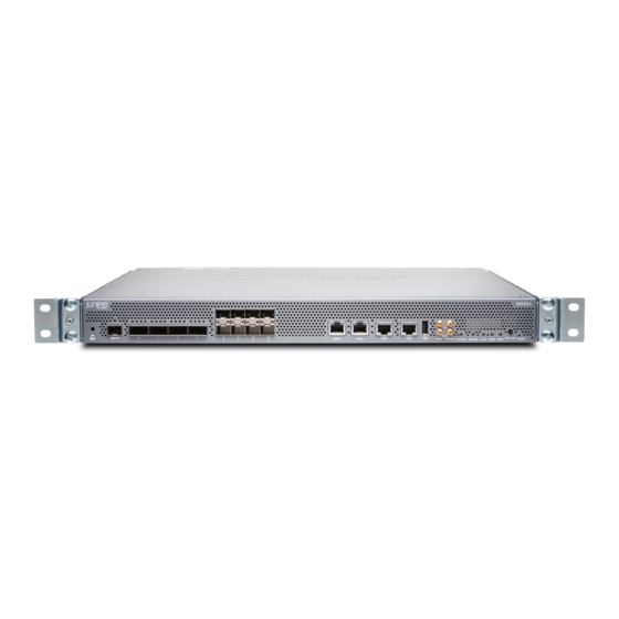
Figure 2: Front View of the MX204 Router The MX204 has four rate-selectable ports that can be configured as 100-Gigabit Ethernet ports or 40-Gigabit Ethernet ports, or each port can be configured as four 10-Gigabit Ethernet ports (by using a breakout cable). - Page 22 Rate selectability at PIC level and port level does not support 1-Gbps speed. For the link to come up, you must configure the no-auto-neg statement on the egress interface. NOTE: For a complete list of supported optics on MX204, see MX204 Transceivers.
-
Page 23: Mx204 Component Redundancy
Only a fully configured router provides complete redundancy. All other configurations provide partial redundancy. The following major hardware components are redundant: Power supplies—The router supports two power supply modules. The MX204 router provides 1+1 redundancy for the system. Both AC and DC systems can withstand the failure of a single power supply without system interruption in 1+1 redundancy mode. -
Page 24: Mx204 Field-Replaceable Units
Replacing an MX204 Fan Module | 124 MX204 Hardware Components and CLI Terminology The MX204 router support the components in Table 4 on page 26, listed in alphabetic order. Table 4: MX204 Router Hardware Components and CLI Terminology Hardware Model Component Number CLI Name... -
Page 25: Mx204 Front And Rear Panel Components
Table 4: MX204 Router Hardware Components and CLI Terminology (continued) Hardware Model Component Number CLI Name Description N/A (built-in) Routing Engine N/A (built-in) RE-S-2X00x6 Transceiver MX Series Interface Xcvr Hardware Compatibility Tool Module Reference. Table 5 on page 27 lists the spare parts and blank panels available for the router. -
Page 26: Rear Panel Components
Chassis Description” on page 23 shows the rear of the fully configured chassis. Table 6 on page 28 lists the components on the rear panel of the MX204 router. Table 6: Rear Panel Components in a Fully Configured MX204 Router Component... -
Page 27: Mx204 Cooling System
MX204 Cooling System IN THIS SECTION MX204 Cooling System Description | 29 MX204 Fan Status LED | 31 MX204 Cooling System Description IN THIS SECTION Fan Trays | 29 Airflow | 30 Power Supply Cooling System | 31 The cooling system components work together to keep all router components within the acceptable temperature range. -
Page 28: Airflow
Figure 6: Fan Module Captive screw Latch — — Airflow The router has front-to-back (AIR OUT) cooling system (see Figure 7 on page 31). Air is pulled through the front the chassis toward the fan tray, where it is exhausted out of the system. -
Page 29: Power Supply Cooling System
Replacing an MX204 DC Power Supply | 130 Replacing an MX204 Fan Module | 124 MX204 Fan Status LED The MX204 fan module does not have any LED—the fan status LEDs are located on the MX204 chassis. Figure 8 on page 32 shows the fan status LEDs. -
Page 30: Mx204 Ac Power System
Fan module is faulty and not functioning normally. steadily – Fan module not present SEE ALSO Replacing an MX204 Fan Module | 124 Maintaining the MX204 Fan Module | 122 MX204 AC Power System IN THIS SECTION MX204 Power System Description | 33... -
Page 31: Mx204 Power System Description
MX204 PSMs. The AC or DC power supply modules directly plug on to main board and are placed on the right side of the rear chassis. Each power supply has a handle, an ejector lever, and status LEDs. The power supply modules connect to the PSM board, which distributes the different output voltages produced by the power supply modules to the router components, depending on their voltage requirements. -
Page 32: Ac Power Supply Description
The power supply modules are cooled by its own internal cooling system. A fan present in the power supply module monitors and maintains the temperature inside. AC Power Supply Description Each AC power supply weighs approximately 2.2 lb (1 kg) and consists of a handle, an ejector lever, an AC appliance inlet, a fan, and status LEDs to monitor the status of the power supply. -
Page 33: Mx204 Power Supply Module Leds
Figure 10: DC Power Supply SEE ALSO Maintaining the MX204 Power Supplies | 126 MX204 Power Supply Module LEDs IN THIS SECTION AC Power Supply Module LEDs | 35 DC Power Supply Module LEDs | 37 AC Power Supply Module LEDs Figure 11 on page 36 shows the AC power supply module components along with the status LEDs. - Page 34 Figure 11: AC Power Supply Module LEDs and Components Input status LED Ejector lever — — Output status LED AC power cord retainer port — — Fault LED — Figure 12 on page 36 shows the AC power supply module components with the AC power cord retainer along with the status LEDs.
-
Page 35: Dc Power Supply Module Leds
Table 9: AC Power Supply Module LEDs (continued) Label Color State Description DC OK Unlit Power supply output is off. Green On steadily The power supply is sending out power correctly. ! (Fault) Amber On steadily An error has been detected in the power supply. Replace the power supply as soon as possible. -
Page 36: Mx204 Router Ac Power Specifications
SEE ALSO Routine Maintenance Procedures for MX204 Routers | 115 Maintaining the MX204 Power Supplies | 126 MX204 Router AC Power Specifications Table 11 on page 39... -
Page 37: Ac Power Circuit Breaker Requirements For The Mx204 Router
SEE ALSO Maintaining the MX204 Power Supplies | 126 AC Power Circuit Breaker Requirements for the MX204 Router We recommend that you use a dedicated customer-site circuit breaker rated for 20 A (110 VAC) minimum or 16 A (220 VAC) minimum for each AC power feed, or as required by local code. Doing so enables you... -
Page 38: Ac Power Cord Specifications For Mx204 Routers
SEE ALSO Replacing an MX204 AC Power Supply | 128 Power Consumption for an AC-Powered MX204 Router | 70 General Safety Guidelines and Warnings | 147 General Electrical Safety Guidelines and Warnings | 172 Prevention of Electrostatic Discharge Damage | 173 AC Power Cord Specifications for MX204 Routers A detachable AC power cord is supplied with the AC power supply modules. - Page 39 Table 13: AC Power Cord Specifications (continued) Country/Region Electrical Specifications Plug Standards Juniper Model Number China 250 VAC, 10 A, 50 Hz GB 1002-1996 Type PRC/3 CBL-EX-PWR-C13-CH Europe (except Italy, 250 VAC, 10 A, 50 Hz CEE (7) VII Type VIIG...
-
Page 40: Mx204 Dc Power System
MX204 DC Power System IN THIS SECTION MX204 Router DC Power Specifications | 42 DC Power Circuit Breaker Requirements for the MX204 Router | 43 DC Power Source Cabling for MX204 Router | 44 DC Power Cable Specifications for MX204 Router | 45... -
Page 41: Dc Power Circuit Breaker Requirements For The Mx204 Router
Maintaining the MX204 Power Supplies | 126 Replacing an MX204 DC Power Supply | 130 DC Power Circuit Breaker Requirements for the MX204 Router Each DC power supply has a single DC input (–48 VDC and return) that requires a dedicated circuit breaker. -
Page 42: Dc Power Source Cabling For Mx204 Router
SEE ALSO Replacing an MX204 DC Power Supply | 130 Power Consumption for a DC-Powered MX204 Router | 72 General Safety Guidelines and Warnings | 147 General Electrical Safety Guidelines and Warnings | 172... -
Page 43: Dc Power Cable Specifications For Mx204 Router
DC Power Cable Specifications for MX204 Router IN THIS SECTION DC Power Cable Lug Specifications | 45 DC Power Cable Specifications | 45 DC Power Cable Lug Specifications The accessory box shipped with the router includes the cable lugs that attach to the terminal of each power supply. -
Page 44: Mx204 Host Subsystem
These routing processes run on top of a kernel that interacts with the Packet Forwarding Engine. The MX204 host subsystem consists of a single built-in Routing Engine. -
Page 45: Routing Engine Components
High-performance 1.6-GHz Intel 8 Core X86 CPU 32-GB DDR4 RAM 100-GB SATA SSD Routing Engine Front Panel Figure 16 on page 47 shows the front panel of the MX204 chassis. Figure 16: MX204 Ports Rate-selectable ports RESET button — —... -
Page 46: Routing Engine Interface Ports
OS supports USB version 1.0 and later. SEE ALSO RJ-45 Connector Pinouts for MX Series CB-RE or RCB Auxillary and Console Ports | 68 RJ-45 Connector Pinouts for an MX Series CB-RE or RCB Management Port | 69 MX204 Chassis Description | 23... -
Page 47: Mx204 Routing Engine Leds
MX204 Routing Engine LEDs The Routing Engine is built-in on the MX204 and is attached to the baseboard and cannot be replaced. The status of the Routing Engine is displayed by the ONLINE and OK/FAIL LEDs on the front panel of the MX204 chassis. - Page 48 Table 16: MX204 LEDs (continued) Label Color State Description Critical alarm—Indicates a critical condition that steadily can cause the router to stop functioning. Possible causes include component failure, or any major software failure. Yellow Warning alarm—Indicates a serious but nonfatal...
-
Page 49: Site Planning, Preparation, And Specifications
Site Planning, Preparation, and Specifications MX204 Site Preparation Checklist | 53 MX204 Site Guidelines and Requirements | 54 MX204 Network Cable and Transceiver Planning | 63 MX204 Management and Console Port Specifications and Pinouts | 68 MX204 Power Planning | 70... -
Page 51: Mx204 Site Preparation Checklist
MX204 Site Preparation Checklist The checklist in Table 17 on page 53 summarizes the tasks you must perform when preparing a site for router installation. Table 17: MX204 Site Preparation Checklist Item or Task For More Information Performed by Date... -
Page 52: Mx204 Site Guidelines And Requirements
RELATED DOCUMENTATION MX204 Installation Overview | 77 Tools Required to Install the MX204 Chassis in Rack | 82 Installing the MX204 Chassis in a Rack | 82 MX204 Site Guidelines and Requirements IN THIS SECTION... -
Page 53: Mx204 Router Physical Specifications
MX204 Router Clearance Requirements for Airflow and Hardware Maintenance | 60 MX204 Router Rack Requirements | 61 MX204 Router Physical Specifications Table 18 on page 55 summarizes the physical specifications for the router. Table 18: Router Physical Specifications Description Weight... - Page 54 Articles 110-16, 110-17, and 110-18 of the National Electrical Code, ANSI/NFPA 70. SEE ALSO Routine Maintenance Procedures for MX204 Routers | 115 General Safety Guidelines for Juniper Networks Devices General Safety Warnings for Juniper Networks Devices | 148...
-
Page 55: Mx204 Router Grounding Specifications
The grounding points are studs sized for 10–32 screws. The 10–32 screws are provided with the MX204 router. The grounding points are spaced at 0.75-in. (19.1-mm) centers. Two threaded holes are provided on the rear left side of the chassis for connecting the router to earth ground. -
Page 56: Grounding Cable Specifications
12 AWG (2.5 mm²) stranded wire, 60° C wire, or as permitted by local code. SEE ALSO Tools and Parts Required for MX204 Router Grounding and Power Connections | 89 Prevention of Electrostatic Discharge Damage | 173 MX204 Router AC Power Specifications | 38... - Page 57 Table 20: Cabinet Requirements and Specifications for an MX204 Router (continued) Cabinet Requirement Guidelines for the MX204 Router Cabinet airflow requirements When you install the router in a cabinet, you must ensure that ventilation through the cabinet is sufficient to prevent overheating. Consider the following requirements to when planning for chassis cooling: Airflow must always be from front to back with respect to the rack.
-
Page 58: Mx204 Router Clearance Requirements For Airflow And Hardware Maintenance
FRUs SEE ALSO MX204 Installation Overview | 77 MX204 Cooling System Description | 29 MX204 Router Clearance Requirements for Airflow and Hardware Maintenance When planning the installation site, allow sufficient clearance around the rack (see Figure 19 on page 61): For the cooling system to function properly, the airflow around the chassis must be unrestricted. -
Page 59: Mx204 Router Rack Requirements
Figure 19: MX204 Chassis Dimensions and Clearance Requirements MX204 Router Rack Requirements The MX204 router can be installed in a standard 19-in. rack. Many types of racks are acceptable, including four-post (telco) racks and open-frame racks. Table 21 on page 61 summarizes rack requirements and specifications for the router. - Page 60 Table 21: Rack Requirements and Specifications for an MX204 Router (continued) Rack Requirement Guidelines Rack size and strength Ensure that the rack is a 19-in. rack as defined in Cabinets, Racks, Panels, and Associated Equipment (document number EIA-310–D) published by the Electronics Components Industry Association (http://www.ecianow.org/).
-
Page 61: Mx204 Network Cable And Transceiver Planning
MX204 Network Cable and Transceiver Planning IN THIS SECTION Calculating Power Budget and Power Margin for Fiber-Optic Cables | 63 CB-RE and RCB Interface Cable and Wire Specifications for MX Series Routers | 65 Understanding Fiber-Optic Cable Signal Loss, Attenuation, and Dispersion | 66... -
Page 62: Calculating Power Margin For Fiber-Optic Cable
= –15 dBm – (–28 dBm) = 13 dB Calculating Power Margin for Fiber-Optic Cable After calculating a link's power budget, you can calculate the power margin (P ), which represents the amount of power available after subtracting attenuation or link loss (LL) from the power budget (P ). -
Page 63: Cb-Re And Rcb Interface Cable And Wire Specifications For Mx Series Routers
= 13 dB – 2 km (1 dB/km) – 5 (0.5 dB) – 2 (0.5 dB) – 0.5 dB = 13 dB – 2 dB – 2.5 dB – 1 dB – 0.5 dB = 7 dB The following sample calculation for an 8-km-long single-mode link with a power budget (P ) of 13 dB uses the estimated values from Table 22 on page 64... -
Page 64: Understanding Fiber-Optic Cable Signal Loss, Attenuation, And Dispersion
Table 23: Cable and Wire Specifications for Routing Engine and RCB Management and Alarm Interfaces (continued) Cable Cable/Wire Maximum Router Port Specification Supplied Length Receptacle Routing Engine Category 5 One 4.57-m 100 m RJ-45 Ethernet cable or length with autosensing interface equivalent RJ-45/RJ-45... -
Page 65: Attenuation And Dispersion In Fiber-Optic Cable
Single-mode fiber is so small in diameter that rays of light can reflect internally through one layer only. Interfaces with single-mode optics use lasers as light sources. Lasers generate a single wavelength of light, which travels in a straight line through the single-mode fiber. Compared with multimode fiber, single-mode fiber has higher bandwidth and can carry signals for longer distances. -
Page 66: Mx204 Management And Console Port Specifications And Pinouts
MX204 Management and Console Port Specifications and Pinouts IN THIS SECTION RJ-45 Connector Pinouts for MX Series CB-RE or RCB Auxillary and Console Ports | 68 RJ-45 Connector Pinouts for an MX Series CB-RE or RCB Management Port | 69... -
Page 67: Connector Pinouts For An Mx Series Cb-Re Or Rcb Management Port
Table 24: RJ-45 Connector Pinout for the AUX and CONSOLE Ports (continued) Signal Description DSR/DCD Data Set Ready Clear to Send RJ-45 Connector Pinouts for an MX Series CB-RE or RCB Management Port The port on the Control Board and Routing Engine (CB-RE; Routing and Control Board (RCB)) labeled MGMT is an autosensing 10/100/1000-Mbps Ethernet RJ-45 receptacle that accepts an Ethernet cable for connecting the Routing Engine to a management LAN (or other device that supports out-of-band management). -
Page 68: Mx204 Power Planning
Transmit/receive data pair 4 MX204 Power Planning IN THIS SECTION Power Consumption for an AC-Powered MX204 Router | 70 Power Consumption for a DC-Powered MX204 Router | 72 Power Consumption for an AC-Powered MX204 Router Use the information in this topic to determine the power consumption for your router and plan the amount of power you need to provide to the router. -
Page 69: Calculating System Thermal Output
Table 27 on page 71 lists the power requirements for the fully configured AC-powered routers operating under typical voltage conditions. Table 27: MX204 Router AC Router Power Requirements at Typical Temperature (25° C) Power Requirement Power Requirement at 25° (Watts) with 90%... -
Page 70: Power Consumption For A Dc-Powered Mx204 Router
Table 30 on page 72 lists the power requirements for the fully configured DC-powered routers operating under typical voltage conditions. Table 30: MX204 Router DC Router Power Requirements at Typical Temperature (25° C) Power Requirement Power Requirement at 25° (Watts) with 90%... -
Page 71: Calculating System Thermal Output
Table 31: MX204 Router DC Router Power Requirements at Maximum Temperature (55° C) Power Requirement Power Requirement at 55° (Watts) with 90% Chassis Configuration C (Watts) Efficiency Fully configured chassis running at high activity 280 W 311 W Calculating System Thermal Output After you have calculated the power consumption for your configuration, you can use that information to determine the system thermal output (BTUs per hour). -
Page 72: Initial Installation And Configuration
MX204 Installation Overview | 77 Unpacking the MX204 | 78 Installing the MX204 | 81 Connecting the MX204 to Power | 89 Connecting the MX204 to the Network | 101 Performing the Initial Software Configuration for the MX204 Router | 108... -
Page 74: Mx204 Installation Overview
See “Verifying the MX204 Router Parts Received” on page 4. (Optional) Remove components from the MX204 router chassis before Installing It in a rack. See individual topics listed in Removing, Installing, and Upgrading Components for removing components. 5. Install the router in the rack. -
Page 75: Unpacking The Mx204
“Powering On an AC-Powered MX204 Router” on page “Powering On a DC-Powered MX204 Router” on page 11. Perform the initial system configuration. “Performing the Initial Software Configuration for the MX204 Router” on page 108. RELATED DOCUMENTATION MX204 Router Rack Requirements | 61... -
Page 76: Unpacking Mx204 Router
6. Verify the contents of the carton against the packing list included with the router. 7. Save the shipping carton and packing materials in case you later need to move or ship the router. SEE ALSO MX204 Site Preparation Checklist | 53... -
Page 77: Verifying The Mx204 Router Parts Received
Verifying the MX204 Router Parts Received A packing list is included in each shipment. Check the parts in the shipment against the items on the packing list. The packing list specifies the part numbers and descriptions of each part in your order. -
Page 78: Installing The Mx204
ESD wrist strap with cable ETSI brackets SEE ALSO MX204 Site Preparation Checklist | 53 Installing the MX204 IN THIS SECTION Tools Required to Install the MX204 Chassis in Rack | 82 Installing the MX204 Chassis in a Rack | 82... -
Page 79: Tools Required To Install The Mx204 Chassis In Rack
Four mounting screws, supplied with the router SEE ALSO MX204 Site Preparation Checklist | 53 Installing the MX204 Chassis in a Rack IN THIS SECTION Installing the MX204 Chassis in a 19-in. Rack | 83 Installing the MX204 in a 21-in. ETSI Rack | 85... -
Page 80: Installing The Mx204 Chassis In A 19-In. Rack
The fully loaded chassis weighs approximately 22.7 lb (10.3 kg). The MX204 router is designed for installation in a rack that complies with either of the following standards: 19-in. rack—A 19-in. (450 mm) rack as defined in Cabinets, Racks, Panels, and Associated Equipment (document number EIA-310-D) published by the Electronics Industry Association (http://www.ecianow.org/). - Page 81 4. Using a Phillips (+) number 2 screwdriver, secure the mounting brackets to the router using the mounting screws. 5. With one person on each side, hold on to the bottom of the chassis and carefully lift it so that the mounting brackets contact the rack rails.
-
Page 82: Installing The Mx204 In A 21-In. Etsi Rack
Figure 24: Router Installed in the Rack Installing the MX204 in a 21-in. ETSI Rack The ETSI racks are little wider than the standard 19-in. rack. To install the router in an ETSI rack, you need to install the ETSI brackets on to the router. - Page 83 Figure 25: ETSI Brackets To install the router in a 21-in. ETSI rack or cabinet: 1. Position the router in front of the rack or cabinet. 2. Attach an electrostatic discharge (ESD) grounding strap to your bare wrist and to a site ESD point. 3.
- Page 84 Figure 28: Installing the Router in a Four-Post Rack 7. Install mounting screws into each of the open front-mounting holes aligned with the rack, starting from the bottom, and secure them tightly. Figure 29 on page 87 shows the router fully secured to the front rails of the four-post rack.
- Page 85 ETSI brackets. Figure 32: Router Installed in the Rack with ETSI Brackets SEE ALSO MX204 Site Preparation Checklist | 53 MX204 Router Grounding Specifications | 57 MX204 Router Clearance Requirements for Airflow and Hardware Maintenance | 60...
-
Page 86: Connecting The Mx204 To Power
Connecting the MX204 to Power IN THIS SECTION Tools and Parts Required for MX204 Router Grounding and Power Connections | 89 Grounding the MX204 Router | 90 Connecting Power to an AC-Powered MX204 Router | 91 Powering On an AC-Powered MX204 Router | 94... -
Page 87: Grounding The Mx204 Router
You must provide the grounding cables (the cable lugs are supplied with the router). For grounding cable specifications, see “MX204 Router Grounding Specifications” on page Figure 33: Grounding Point on the MX204 Router Rear panel Grounding point —... -
Page 88: Connecting Power To An Ac-Powered Mx204 Router
9. Dress the grounding cable, and verify that it does not touch or block access to router components, and that it does not drape where people could trip on it. Figure 34: Connecting Grounding Lug to the MX204 Router SEE ALSO... - Page 89 1. Locate power cords that have a plug appropriate for your geographic location. For more information, “AC Power Cord Specifications for MX204 Routers” on page 2. Attach an ESD grounding strap to your bare wrist and connect the strap to one of the ESD points on the chassis.
- Page 90 Figure 36: Power Cord Retainer Installed on the AC Power Supply Module Input status LED AC power cord retainer installed — — Output status LED Ejector lever — — Fault LED — 6. Press the small tab on the retainer strip to loosen the loop. Slide the loop until you have enough space to insert the power cord coupler into the inlet.
-
Page 91: Powering On An Ac-Powered Mx204 Router
SEE ALSO MX204 Router Grounding Specifications | 57 General Safety Guidelines and Warnings | 147 General Electrical Safety Guidelines and Warnings | 172 Prevention of Electrostatic Discharge Damage | 173 Powering On an AC-Powered MX204 Router To power on an AC-powered router: 1. -
Page 92: Connecting Power To A Dc-Powered Mx204 Router
General Safety Guidelines and Warnings | 147 General Electrical Safety Guidelines and Warnings | 172 Prevention of Electrostatic Discharge Damage | 173 Connecting Power to a DC-Powered MX204 Router CAUTION: Do not mix AC and DC power supply modules within the same router. Damage... - Page 93 You must provide the power cables (the cable lugs are supplied with the router). For power cable specifications, see “DC Power Cable Specifications for MX204 Router” on page To connect the DC source power cables to the router for each power supply: 1.
- Page 94 7. Repeat Step through Step for installing the other power supply modules. Figure 38: Connecting DC Power to the Router SEE ALSO MX204 Router Grounding Specifications | 57 General Safety Guidelines and Warnings | 147...
-
Page 95: Powering On A Dc-Powered Mx204 Router
General Electrical Safety Guidelines and Warnings | 172 Prevention of Electrostatic Discharge Damage | 173 Powering On a DC-Powered MX204 Router To power on a DC-powered router: 1. Verify that an external management device is connected to the CON port on the chassis. -
Page 96: Powering Off The Mx204 Router
Before you power off an MX204: Ensure that you have taken the necessary precautions to prevent electrostatic discharge (ESD) damage. “Prevention of Electrostatic Discharge Damage” on page 173. Ensure that you do not need to route traffic through the MX204. - Page 97 Ensure that you have the following parts and tools available to power off the MX204: An ESD grounding strap An external management device such as a PC An RJ-45 to DB-9 rollover cable to connect the external management device to the console port NOTE: After powering off a power supply, wait at least 60 seconds before turning it back on.
-
Page 98: Connecting The Mx204 To The Network
Connecting the MX204 to the Network IN THIS SECTION Tools and Parts Required to Connect the MX204 Router to External Devices | 101 Connecting the MX204 Router to External Devices and Cables | 102 Tools and Parts Required to Connect the MX204 Router to External Devices To connect the router to external devices, you need the following tools and parts: 2.5-mm flat-blade (–) screwdriver for the alarm relay contacts... -
Page 99: Connecting The Mx204 Router To External Devices And Cables
Connecting the Router to External Clocking and Timing Devices | 105 Figure 39 on page 102 shows the front panel of the MX204 router. All the connections to the router are made through the front panel. Figure 39: MX204 Front Panel Ports, LEDs and Buttons... -
Page 100: Connecting The Router To A Network For Out-Of-Band Management
104). The console port accepts a cable with an RJ-45 connector. One serial cable with an RJ-45 connector and a DB-9 connector is provided with the router. NOTE: Use shielded CAT5e cable for connecting the CON and MGMT ports on the MX204 router. - Page 101 Data bits—8 Stop bits—1 Flow control—none Figure 41: Console and Auxiliary Cable Connector Figure 42: Connecting the MX204 Router to a Management Console Through a Console Server To Console port Console server Figure 43: Connecting the MX204 Router Directly to a Management Console...
-
Page 102: Connecting The Router To External Clocking And Timing Devices
10-MHz-OUT timing ports. NOTE: MX204 can be configured as a timing master or a slave device. If the MX204 is configured as a timing master device, the router gets 1-PPS-IN and 10-MHz-IN input (connected to the ports marked IN) from the timing source and sends 1-PPS-OUT and 10-MHz-OUT to a slave device. If the MX204 is configured as a timing slave device, it receives 1-PPS-IN and 10-MHz-IN (connected to ports marked IN) as input from the timing source. - Page 103 Ensure that the 10-MHz and 1-PPS source network equipment contains a low voltage complementary metal oxide semiconductor (LVCMOS) of 50 ohms or is compatible with low-voltage transistor-transistor logic (LVTTL) (3.3v). Figure 44: Clocking Ports on the MX204 Router Table 36: Clocking Ports on the MX204 Router Label...
- Page 104 3. Plug the other end of the RJ-45 cable into the ToD timing device. 4. Verify that the LEDs for the ToD port on the router are lit steadily green. 5. Configure the port. See Configuring Clock Synchronization Interface on MX Series Routers. Table 37: Time-of-Day Port on the MX204 Router Callout Label Description ToD RJ-45 port with LED.
-
Page 105: Performing The Initial Software Configuration For The Mx204 Router
Table 38: BITS Port on the MX204 Router Callout Label Description BITS Building-Integrated Timing Supply (BITS) clock interface port with LED. (See Figure 39 on page 102) SEE ALSO MX204 Routing Engine Description | 46 Prevention of Electrostatic Discharge Damage | 173... - Page 106 This procedure connects the router to the network but does not enable it to forward traffic. For complete information about enabling the router to forward traffic, including examples, see the Junos OS configuration guides. To configure the software: 1. Verify that the router is powered on. 2.
- Page 107 [edit] root@# set system domain-name domain-name 9. Configure the IP address and prefix length for the router’s Ethernet interface. [edit] root@# set interfaces fxp0 unit 0 family inet address address/prefix-length 10. Configure the IP address of a backup router, which is used only while the routing protocol is not running. [edit] root@# set system backup-router address 11.
- Page 108 root@# set system root-authentication ssh-rsa public-key 13. (Optional) Configure the static routes to remote subnets with access to the management port. Access to the management port is limited to the local subnet. To access the management port from a remote subnet, you need to add a static route to that subnet within the routing table.
- Page 109 16. Commit the configuration to activate it on the router. [edit] root@# commit 17. (Optional) Configure additional properties by adding the necessary configuration statements. Then commit the changes to activate them on the router. [edit] root@host# commit 18. When you have finished configuring the router, exit configuration mode. [edit] root@host# exit root@host>...
-
Page 110: Maintaining Components
C HAPTER Maintaining Components Maintaining MX204 Components | 115 Maintaining MX204 Cooling System Components | 122 Maintaining MX204 Power System Components | 126... -
Page 112: Maintaining Mx204 Components
Check the status-reporting devices on the font panel—system alarms and LEDs. SEE ALSO Alarm LEDs on the MX204 Front Panel | 28 Maintaining the MX204 Routing Engine Purpose For optimum router performance, verify the condition of the Routing Engine on a regular basis. - Page 113 To check the status of the Routing Engine on the router, issue the show chassis routing-engine command. The output is similar to the following: user@host> show chassis routing-engine Routing Engine status: Temperature 53 degrees C / 127 degrees F CPU temperature 53 degrees C / 127 degrees F DRAM 16341 MB (16384 MB installed)
-
Page 114: Replace An Sfp+ Transceiver
MX204 Routing Engine Description | 46 MX204 Routing Engine LEDs | 49 show chassis routing-engine Replace an SFP+ Transceiver IN THIS SECTION Remove an SFP+ Transceiver | 117 Install an SFP+ Transceiver | 119 Small form-factor pluggable plus transceivers (SFP+) are enhanced SFP transceivers that provide support for data rates of up to 10 Gbps for fiber-optic or copper interfaces. - Page 115 3. Label the cables connected to the transceiver so that you can reconnect them correctly later. 4. Remove the cable connector from the transceiver. Immediately cover the transceiver and the end of the cable with a rubber safety cap. WARNING: Do not look directly into a fiber-optic transceiver or into the ends of fiber-optic cables.
-
Page 116: Install An Sfp+ Transceiver
Install an SFP+ Transceiver To install an SFP+ transceiver: 1. Wrap and fasten one end of the ESD grounding strap around your bare wrist, and connect the other end of the strap to the ESD point on the chassis. 2. Take each transceiver to be installed out of its electrostatic bag, and identify the slot on the component where you will install it. -
Page 117: Remove A Qsfp28 Transceiver
28-Gbps quad small form-factor pluggable (QSFP28) transceivers are hot-insertable and hot-removable. Removing a QSFP28 transceiver does not interrupt router functioning, but the removed QSFP28 transceiver no longer receives or transmits data. Remove a QSFP28 Transceiver To remove a QSFP28 transceiver (see Figure 46 on page 121): 1. -
Page 118: Install A Qsfp28 Transceiver
CAUTION: Avoid bending fiber-optic cable beyond its minimum bend radius. An arc smaller than a few inches in diameter can damage the cable and cause problems that are difficult to diagnose. 6. Pull the transceiver’s rubber handle straight back. The locking pins on the transceiver automatically releases the transceiver. -
Page 119: Maintaining Mx204 Cooling System Components
You can also verify interface port functioning by issuing the show chassis fpc pic-status command. Maintaining MX204 Cooling System Components IN THIS SECTION Maintaining the MX204 Fan Module | 122 Replacing an MX204 Fan Module | 124 Maintaining the MX204 Fan Module... - Page 120 For optimum cooling, verify the condition of the fans. Action Monitor the status of the fans. A fan module contains multiple fans that work in unison to cool the router components. If one fan fails, the router adjusts the speed of the remaining fans to maintain proper cooling.
-
Page 121: Replacing An Mx204 Fan Module
MX204 Cooling System Description | 29 show chassis environment Replacing an MX204 Fan Module IN THIS SECTION Removing an MX204 Fan Module | 124 Installing an MX204 Fan Module | 125 Removing an MX204 Fan Module NOTE: To prevent overheating, install the replacement fan module immediately after removing the existing fan module. -
Page 122: Installing An Mx204 Fan Module
4. Using a number-2 Phillips screwdriver, turn the locking screw on the fan module faceplate until it is tight and secured. Figure 48: Installing the Fan Module SEE ALSO MX204 Cooling System Description | 29 Prevention of Electrostatic Discharge Damage | 173... -
Page 123: Maintaining Mx204 Power System Components
Maintaining MX204 Power System Components IN THIS SECTION Maintaining the MX204 Power Supplies | 126 Replacing an MX204 AC Power Supply | 128 Replacing an MX204 DC Power Supply | 130 Maintaining the MX204 Power Supplies Purpose For optimum router performance, verify the condition of the power supply modules. - Page 124 CAUTION: Do not mix AC and DC power supplies in the same chassis. SEE ALSO MX204 Power System Description | 33 MX204 Power Supply Module LEDs | 35...
-
Page 125: Replacing An Mx204 Ac Power Supply
Replacing an MX204 AC Power Supply IN THIS SECTION Removing an MX204 AC Power Supply | 128 Installing an MX204 AC Power Supply | 129 Removing an MX204 AC Power Supply Before you remove a power supply, be aware of the following:... -
Page 126: Installing An Mx204 Ac Power Supply
Figure 49 on page 129). 5. Pull the power supply straight out of the chassis. Figure 49: Removing an AC Power Supply Installing an MX204 AC Power Supply To install an AC power supply (see Figure 50 on page 130): 1. -
Page 127: Replacing An Mx204 Dc Power Supply
SEE ALSO MX204 Power System Description | 33 MX204 Router AC Power Specifications | 38 AC Power Circuit Breaker Requirements for the MX204 Router | 39 Prevention of Electrostatic Discharge Damage | 173 Replacing an MX204 DC Power Supply IN THIS SECTION... - Page 128 WARNING: Before performing DC power procedures, ensure that power is removed from the DC circuit. To ensure that all power is off, locate the circuit breaker on the panel board that services the DC circuit, switch the circuit breaker to the off position, and tape the switch handle of the circuit breaker in the off position.
-
Page 129: Installing An Mx204 Dc Power Supply
132). Figure 51: Disconnecting the DC Power Cables Figure 52: Removing a DC Power Supply Installing an MX204 DC Power Supply WARNING: Before performing DC power procedures, ensure that power is removed from the DC circuit. To ensure that all power is off, locate the circuit breaker on the panel board that services the DC circuit, switch the circuit breaker to the off position, and tape the switch handle of the circuit breaker in the off position. - Page 130 3. Using both hands, slide the DC power supply straight into the chassis until the power supply is fully seated in the chassis slot. The power supply faceplate must alligned with any adjacent power supply faceplate or blank installed in the power supply slot. 4.
- Page 131 MX204 Power System Description | 33 MX204 Router DC Power Specifications | 42 DC Power Circuit Breaker Requirements for the MX204 Router | 43 DC Power Source Cabling for MX204 Router | 44 DC Power Cable Specifications for MX204 Router | 45...
-
Page 132: Contacting Customer Support And Returning The Chassis Or Components | 137
C HAPTER Contacting Customer Support and Returning the Chassis or Components Contacting Customer Support and Returning the Chassis or Components | 137... -
Page 134: Contacting Customer Support
Guidelines for Packing Hardware Components for Shipment | 142 Contacting Customer Support You can contact Juniper Networks Technical Assistance Center (JTAC) 24 hours a day, 7 days a week in one of the following ways: On the Web, using the Service Request Manager link at: https://support.juniper.net/support/... -
Page 135: Contacting Customer Support To Obtain Return Material Authorization
The support representative validates your request and issues an RMA number for return of the component. Contacting Customer Support to Obtain Return Material Authorization If you are returning a device or hardware component to Juniper Networks for repair or replacement, obtain a Return Material Authorization (RMA) number from Juniper Networks Technical Assistance Center (JTAC). -
Page 136: Locating The Serial Number On An Mx204 Router Or Component
Locating the Serial Number ID Label on an MX204 Fan Module | 141 If you are returning a router or component to Juniper Networks for repair or replacement, you must locate the serial number of the router or component. You must provide the serial number to the Juniper Networks Technical Assistance Center (JTAC) when you contact them to obtain a Return Materials Authorization (RMA). -
Page 137: Locating The Chassis Serial Number Id Label On An Mx204
Locating the Serial Number ID Labels on MX204 Power Supplies The power supplies installed in an MX204 are field-replaceable units (FRUs). For each FRU, you must remove the FRU from the router chassis to see the FRU serial number ID label. -
Page 138: Locating The Serial Number Id Label On An Mx204 Fan Module
Locating the Serial Number ID Label on an MX204 Fan Module The fan modules installed in an MX204 are field-replaceable units (FRUs). For each FRU, you must remove the FRU from the router chassis to see the FRU serial number ID label. -
Page 139: Guidelines For Packing Hardware Components For Shipment
Figure 58: MX204 Fan Module Serial Number Location Serial number ID label SEE ALSO MX204 Hardware Components and CLI Terminology | 26 Guidelines for Packing Hardware Components for Shipment To pack and ship individual components: When you return components, make sure that they are adequately protected with packing materials and packed so that the pieces are prevented from moving around inside the carton. -
Page 140: Safety And Compliance Information
Safety and Compliance Information Definitions of Safety Warning Levels | 145 General Safety Guidelines and Warnings | 147 General Safety Warnings for Juniper Networks Devices | 148 Fire Safety Requirements | 152 Installation Instructions Warning | 154 Chassis and Component Lifting Guidelines | 154... - Page 141 Action to Take After an Electrical Accident | 189 Agency Approvals for MX204 Router | 190 Compliance Statements for NEBS | 191 Compliance Statements for EMC Requirements | 192 Compliance Statements for Environmental Requirements | 194 Compliance Statements for Acoustic Noise for MX204 Router | 194...
-
Page 142: Definitions Of Safety Warning Levels
Definitions of Safety Warning Levels The documentation uses the following levels of safety warnings (there are two Warning formats): NOTE: You might find this information helpful in a particular situation, or you might overlook this important information if it was not highlighted in a Note. CAUTION: You need to observe the specified guidelines to prevent minor injury or discomfort to you or severe damage to the device. - Page 143 WARNING: This symbol means danger. You are in a situation that could cause bodily injury. Before you work on any equipment, be aware of the hazards involved with electrical circuitry and be familiar with standard practices for preventing accidents. Waarschuwing Dit waarschuwingssymbool betekent gevaar. U verkeert in een situatie die lichamelijk letsel kan veroorzaken.
-
Page 144: General Safety Guidelines And Warnings
Varning! Denna varningssymbol signalerar fara. Du befinner dig i en situation som kan leda till personskada. Innan du utför arbete på någon utrustning måste du vara medveten om farorna med elkretsar och känna till vanligt förfarande för att förebygga skador. General Safety Guidelines and Warnings The following guidelines help ensure your safety and protect the device from damage. -
Page 145: General Safety Warnings For Juniper Networks Devices
Always ensure that all modules, power supplies, and cover panels are fully inserted and that the installation screws are fully tightened. General Safety Warnings for Juniper Networks Devices IN THIS SECTION Qualified Personnel Warning | 149... -
Page 146: Qualified Personnel Warning
Qualified Personnel Warning WARNING: Only trained and qualified personnel should install or replace the hardware equipment. Waarschuwing Installatie en reparaties mogen uitsluitend door getraind en bevoegd personeel uitgevoerd worden. Varoitus Ainoastaan koulutettu ja pätevä henkilökunta saa asentaa tai vaihtaa tämän laitteen. -
Page 147: Restricted-Access Area Warning
Restricted-Access Area Warning... - Page 148 WARNING: The hardware equipment is intended for installation in restricted-access areas. A restricted-access area is an area to which access can be gained only by service personnel through the use of a special tool, lock and key, or other means of security, and which is controlled by the authority responsible for the location.
-
Page 149: Fire Safety Requirements
In addition, you should establish procedures to protect your equipment in the event of a fire emergency. Juniper Networks products should be installed in an environment suitable for electronic equipment. We recommend that fire suppression equipment be available in the event of a fire in the vicinity of the equipment and that all local fire, safety, and electrical codes and ordinances be observed when you install and operate your equipment. -
Page 150: Fire Suppression Equipment
To keep warranties effective, do not use a dry chemical fire extinguisher to control a fire at or near a Juniper Networks device. If a dry chemical fire extinguisher is used, the unit is no longer eligible for coverage under a service agreement. -
Page 151: Installation Instructions Warning
Installation Instructions Warning WARNING: Read the installation instructions before you connect the device to a power source. Waarschuwing Raadpleeg de installatie-aanwijzingen voordat u het systeem met de voeding verbindt. Varoitus Lue asennusohjeet ennen järjestelmän yhdistämistä virtalähteeseen. Attention Avant de brancher le système sur la source d'alimentation, consulter les directives d'installation. -
Page 152: Ramp Warning
Up to 39.7 lb (18 kg): One person. 39.7 lb (18 kg) to 70.5 lb (32 kg): Two or more people. 70.5 lb (32 kg) to 121.2 lb (55 kg): Three or more people. Above 121.2 lbs (55 kg): Material handling systems (such as levers, slings, lifts and so on) must be used. When this is not practical, specially trained persons or systems must be used (riggers or movers). - Page 153 De onderstaande richtlijnen worden verstrekt om uw veiligheid te verzekeren: De Juniper Networks switch moet in een stellage worden geïnstalleerd die aan een bouwsel is verankerd. Dit toestel dient onderaan in het rek gemonteerd te worden als het toestel het enige in het rek is.
- Page 154 Les directives ci-dessous sont destinées à assurer la protection du personnel: Le rack sur lequel est monté le Juniper Networks switch doit être fixé à la structure du bâtiment. Si cette unité constitue la seule unité montée en casier, elle doit être placée dans le bas.
- Page 155 Para garantizar su seguridad, proceda según las siguientes instrucciones: El Juniper Networks switch debe instalarse en un bastidor fijado a la estructura del edificio. Colocar el equipo en la parte inferior del bastidor, cuando sea la única unidad en el mismo.
-
Page 156: Laser And Led Safety Guidelines And Warnings
Class 1 LED Product Warning | 161 Laser Beam Warning | 162 Juniper Networks devices are equipped with laser transmitters, which are considered a Class 1 Laser Product by the U.S. Food and Drug Administration and are evaluated as a Class 1 Laser Product per EN 60825-1 requirements. -
Page 157: Class 1 Laser Product Warning
Do not look into unterminated ports or at fibers that connect to unknown sources. Do not examine unterminated optical ports with optical instruments. Avoid direct exposure to the beam. WARNING: Unterminated optical connectors can emit invisible laser radiation. The lens in the human eye focuses all the laser power on the retina, so focusing the eye directly on a laser source—even a low-power laser—could permanently damage the eye. -
Page 158: Class 1 Led Product Warning
Class 1 LED Product Warning WARNING: Class 1 LED product. Waarschuwing Klasse 1 LED-product. Varoitus Luokan 1 valodiodituote. Attention Alarme de produit LED Class I. Warnung Class 1 LED-Produktwarnung. Avvertenza Avvertenza prodotto LED di Classe 1. Advarsel LED-produkt i klasse 1. Aviso Produto de classe 1 com LED. -
Page 159: Laser Beam Warning
Laser Beam Warning WARNING: Do not stare into the laser beam or view it directly with optical instruments. Waarschuwing Niet in de straal staren of hem rechtstreeks bekijken met optische instrumenten. Varoitus Älä katso säteeseen äläkä tarkastele sitä suoraan optisen laitteen avulla. Attention Ne pas fixer le faisceau des yeux, ni l'observer directement à... -
Page 160: Radiation From Open Port Apertures Warning
Radiation from Open Port Apertures Warning WARNING: Because invisible radiation might be emitted from the aperture of the port when no fiber cable is connected, avoid exposure to radiation and do not stare into open apertures. Waarschuwing Aangezien onzichtbare straling vanuit de opening van de poort kan komen als er geen fiberkabel aangesloten is, dient blootstelling aan straling en het kijken in open openingen vermeden te worden. -
Page 161: Maintenance And Operational Safety Guidelines And Warnings
Maintenance and Operational Safety Guidelines and Warnings IN THIS SECTION Battery Handling Warning | 165 Jewelry Removal Warning | 166 Lightning Activity Warning | 168 Operating Temperature Warning | 169 Product Disposal Warning | 171 While performing the maintenance activities for devices, observe the following guidelines and warnings:... -
Page 162: Battery Handling Warning
Battery Handling Warning WARNING: Replacing a battery incorrectly might result in an explosion. Replace a battery only with the same or equivalent type recommended by the manufacturer. Dispose of used batteries according to the manufacturer's instructions. Waarschuwing Er is ontploffingsgevaar als de batterij verkeerd vervangen wordt. Vervang de batterij slechts met hetzelfde of een equivalent type dat door de fabrikant aanbevolen is. -
Page 163: Jewelry Removal Warning
Jewelry Removal Warning... - Page 164 WARNING: Before working on equipment that is connected to power lines, remove jewelry, including rings, necklaces, and watches. Metal objects heat up when connected to power and ground and can cause serious burns or can be welded to the terminals. Waarschuwing Alvorens aan apparatuur te werken die met elektrische leidingen is verbonden, sieraden (inclusief ringen, kettingen en horloges) verwijderen.
-
Page 165: Lightning Activity Warning
Varning! Tag av alla smycken (inklusive ringar, halsband och armbandsur) innan du arbetar på utrustning som är kopplad till kraftledningar. Metallobjekt hettas upp när de kopplas ihop med ström och jord och kan förorsaka allvarliga brännskador; metallobjekt kan också sammansvetsas med kontakterna. Lightning Activity Warning WARNING: Do not work on the system or connect or disconnect cables during periods... -
Page 166: Operating Temperature Warning
Operating Temperature Warning... - Page 167 6 in. (15.2 cm) of clearance around the ventilation openings. Waarschuwing Om te voorkomen dat welke switch van de Juniper Networks router dan ook oververhit raakt, dient u deze niet te bedienen op een plaats waar de maximale aanbevolen omgevingstemperatuur van 40°...
-
Page 168: Product Disposal Warning
Varning! Förhindra att en Juniper Networks switch överhettas genom att inte använda den i ett område där den maximalt rekommenderade omgivningstemperaturen på 40° C överskrids. Förhindra att luftcirkulationen inskränks genom att se till att det finns fritt utrymme på minst 15,2 cm omkring ventilationsöppningarna. -
Page 169: General Electrical Safety Guidelines And Warnings
General Electrical Safety Guidelines and Warnings WARNING: Certain ports on the device are designed for use as intrabuilding (within-the-building) interfaces only (Type 2 or Type 4 ports as described in GR-1089-CORE) and require isolation from the exposed outside plant (OSP) cabling. To comply with NEBS requirements and protect against lightning surges and commercial power disturbances, the intrabuilding ports must not be metallically connected to interfaces that connect to the OSP or its wiring. -
Page 170: Prevention Of Electrostatic Discharge Damage
Operate the device within marked electrical ratings and product usage instructions. To ensure that the device and peripheral equipment function safely and correctly, use the cables and connectors specified for the attached peripheral equipment, and make certain they are in good condition. You can remove and replace many device components without powering off or disconnecting power to the device, as detailed elsewhere in the hardware documentation for this device. -
Page 171: Site Electrical Wiring Guidelines
Figure 59: Placing a Component into an Antistatic Bag CAUTION ELECTROSTATIC SENSITIVE DEVICES DO NOT OPEN OR HANDLE EXCEPT AT A STATIC-FREE WORKSTATION CAUTION: ANSI/TIA/EIA-568 cables such as Category 5e and Category 6 can get electrostatically charged. To dissipate this charge, always ground the cables to a suitable and safe earth ground before connecting them to the system. -
Page 172: Ac Power Electrical Safety Guidelines
Table 39: Site Electrical Wiring Guidelines Site Wiring Factor Guidelines Signaling limitations If your site experiences any of the following problems, consult experts in electrical surge suppression and shielding: Improperly installed wires cause radio frequency interference (RFI). Damage from lightning strikes occurs when wires exceed recommended distances or pass between buildings. - Page 173 The following electrical safety guidelines apply to AC-powered devices: Note the following warnings printed on the device: “CAUTION: THIS UNIT HAS MORE THAN ONE POWER SUPPLY CORD. DISCONNECT ALL POWER SUPPLY CORDS BEFORE SERVICING TO AVOID ELECTRIC SHOCK.” “ATTENTION: CET APPAREIL COMPORTE PLUS D'UN CORDON D'ALIMENTATION. AFIN DE PRÉVENIR LES CHOCS ÉLECTRIQUES, DÉBRANCHER TOUT CORDON D'ALIMENTATION AVANT DE FAIRE LE DÉPANNAGE.”...
-
Page 174: Ac Power Disconnection Warning
AC Power Disconnection Warning WARNING: Before working on the device or near power supplies, unplug all the power cords from an AC-powered device. Waarschuwing Voordat u aan een frame of in de nabijheid van voedingen werkt, dient u bij wisselstroom toestellen de stekker van het netsnoer uit het stopcontact te halen. Varoitus Kytke irti vaihtovirtalaitteiden virtajohto, ennen kuin teet mitään asennuspohjalle tai työskentelet virtalähteiden läheisyydessä. -
Page 175: Dc Power Disconnection Warning
DC Power Disconnection Warning... - Page 176 WARNING: Before performing any of the DC power procedures, ensure that power is removed from the DC circuit. To ensure that all power is off, locate the circuit breaker on the panel board that services the DC circuit, switch the circuit breaker to the OFF position, and tape the device handle of the circuit breaker in the OFF position.
-
Page 177: Dc Power Grounding Requirements And Warning
corrente contínua e coloque-o na posição OFF (Desligado), segurando nessa posição a manivela do interruptor do disjuntor com fita isoladora. ¡Atención! Antes de proceder con los siguientes pasos, comprobar que la alimentación del circuito de corriente continua (CC) esté cortada (OFF). Para asegurarse de que toda la alimentación esté... - Page 178 WARNING: When you install the device, the ground connection must always be made first and disconnected last. Waarschuwing Bij de installatie van het toestel moet de aardverbinding altijd het eerste worden gemaakt en het laatste worden losgemaakt. Varoitus Laitetta asennettaessa on maahan yhdistäminen aina tehtävä ensiksi ja maadoituksen irti kytkeminen viimeiseksi.
-
Page 179: Dc Power Wiring Sequence Warning
DC Power Wiring Sequence Warning... - Page 180 WARNING: Wire the DC power supply using the appropriate lugs. When connecting power, the proper wiring sequence is ground to ground, +RTN to +RTN, then –48 V to –48 V. When disconnecting power, the proper wiring sequence is –48 V to –48 V, +RTN to +RTN, then ground to ground.
- Page 181 último. Observe que el alambre de tierra se debe conectar siempre primero y desconectar por último. ¡Atención! Wire a fonte de alimentação de DC Usando os talões apropriados na extremidade da fiação. Ao conectar a potência, a seqüência apropriada da fiação é moída para moer, +RTN a +RTN, então –48 V a –48 V.
-
Page 182: Dc Power Wiring Terminations Warning
DC Power Wiring Terminations Warning... - Page 183 WARNING: When stranded wiring is required, use approved wiring terminations, such as closed-loop or spade-type with upturned lugs. These terminations must be the appropriate size for the wires and must clamp both the insulation and conductor. Waarschuwing Wanneer geslagen bedrading vereist is, dient u bedrading te gebruiken die voorzien is van goedgekeurde aansluitingspunten, zoals het gesloten-lus type of het grijperschop type waarbij de aansluitpunten omhoog wijzen.
- Page 184 hacia arriba. Estos terminales deberán ser del tamaño apropiado para los cables que se utilicen, y tendrán que sujetar tanto el aislante como el conductor. Varning! När flertrådiga ledningar krävs måste godkända ledningskontakter användas, t.ex. kabelsko av sluten eller öppen typ med uppåtvänd tapp. Storleken på dessa kontakter måste vara avpassad till ledningarna och måste kunna hålla både isoleringen och ledaren fastklämda.
-
Page 185: Multiple Power Supplies Disconnection Warning
Multiple Power Supplies Disconnection Warning WARNING: The network device has more than one power supply connection. All connections must be removed completely to remove power from the unit completely. Waarschuwing Deze eenheid heeft meer dan één stroomtoevoerverbinding; alle verbindingen moeten volledig worden verwijderd om de stroom van deze eenheid volledig te verwijderen. -
Page 186: Tn Power Warning
TN Power Warning WARNING: The device is designed to work with a TN power system. Waarschuwing Het apparaat is ontworpen om te functioneren met TN energiesystemen. Varoitus Koje on suunniteltu toimimaan TN-sähkövoimajärjestelmien yhteydessä. Attention Ce dispositif a été conçu pour fonctionner avec des systèmes d'alimentation Warnung Das Gerät ist für die Verwendung mit TN-Stromsystemen ausgelegt. -
Page 187: Agency Approvals For Mx204 Router
Agency Approvals for MX204 Router The router comply with the following standards: Safety CAN/CSA-C22.2 No. 60950-1, Safety of Information Technology Equipment UL 60950-1 Information Technology Equipment - Safety - Part 1: General Requirements EN 60950-1 European Norm, Safety of Information Technology Equipment... -
Page 188: Compliance Statements For Nebs
GR-1089-Core: EMC and Electrical Safety for Network Telecommunications Equipment SR-3580 NEBS Criteria Levels (Level 3 Compliance) RELATED DOCUMENTATION MX204 Router Overview | 21 Compliance Statements for NEBS The equipment is suitable for installation as part of the Common Bonding Network (CBN). -
Page 189: Compliance Statements For Emc Requirements
The battery return connection is to be treated as an isolated DC return (that is, DC-I), as defined in GR-1089-CORE. You must provision a readily accessible device outside of the equipment to disconnect power. The device must also be rated based on local electrical code practice. Compliance Statements for EMC Requirements IN THIS SECTION Canada | 192... -
Page 190: Israel
Israel Translation from Hebrew—Warning: This product is Class A. In residential environments, the product might cause radio interference, and in such a situation, the user might be required to take adequate measures. Japan The preceding translates as follows: This is a Class A product based on the standard of the Voluntary Control Council for Interference by Information Technology Equipment (VCCI). -
Page 191: Compliance Statements For Environmental Requirements
EU Directives 91/157/EEC, 93/86/EEC, and 98/101/EEC. The product documentation includes instructional information about the proper method of reclamation and recycling. Compliance Statements for Acoustic Noise for MX204 Router The router complies with NEBS Level 3 requirements:...
Need help?
Do you have a question about the MX204 and is the answer not in the manual?
Questions and answers