Juniper MX240 Hardware Manual
Ethernet services router
Hide thumbs
Also See for MX240:
- Hardware manual (512 pages) ,
- Instruction for upgrading (35 pages) ,
- Quick start manual (31 pages)

Related Manuals for Juniper MX240


Summary of Contents for Juniper MX240
-
Page 1: Hardware Guide
MX240 Ethernet Services Router Hardware Guide Juniper Networks, Inc. 1194 North Mathilda Avenue Sunnyvale, California 94089 408-745-2000 www.juniper.net Part Number: 530-022140-01, Revision 2... - Page 2 Products made or sold by Juniper Networks or components thereof might be covered by one or more of the following patents that are owned by or licensed to Juniper Networks: U.S. Patent Nos. 5,473,599, 5,905,725, 5,909,440, 6,192,051, 6,333,650, 6,359,479, 6,406,312, 6,429,706, 6,459,579, 6,493,347, 6,538,518, 6,538,899, 6,552,918, 6,567,902, 6,578,186, and 6,590,785.
- Page 3 (g) distribute any key for the Software provided by Juniper to any third party; (h) use the Software in any manner that extends or is broader than the uses purchased by Customer from Juniper or an authorized Juniper reseller;...
- Page 4 (or services are accessed by) the Software shall be a third party beneficiary with respect to this Agreement, and such licensor or vendor shall have the right to enforce this Agreement in its own name as if it were Juniper. In addition, certain third party software may be provided with the Software and is subject to the accompanying license(s), if any, of its respective owner(s).
-
Page 5: Table Of Contents
Audience .....................xvii Documentation Conventions ..............xviii List of Technical Publications ................xix Obtaining Documentation ................xxvi Documentation Feedback ................xxvi Requesting Technical Support ..............xxvii Part 1 MX240 Router Overview Chapter 1 Router Overview Router Description ..................3 Component Redundancy .................4 Chapter 2 Hardware Components Router Chassis ....................5 Midplane ......................8... - Page 6 Alarm Relay Contacts ................21 Power Supplies ....................21 AC Power Supply ..................21 AC Power Supply LEDs ..............22 DC Power Supply ..................23 DC Power Supply Configurations for the MX240 Router ....23 DC Power Supply LEDs ..............24 Cooling System .....................24 Part 2 Setting Up the Router...
- Page 7 Table of Contents Chapter 8 Connecting the Router Tools and Parts Required ................49 Connecting the Router to Management and Alarm Devices ......49 Connecting to a Network for Out-of-Band Management ......50 Connecting to a Management Console or Auxiliary Device .....50 Connecting to an External Alarm-Reporting Device ........50 Connecting DPC Cables .................51 Chapter 9 Grounding and Providing Power to the Router...
- Page 8 MX240 Ethernet Services Router Hardware Guide Chapter 12 Troubleshooting Hardware Components Overview of Troubleshooting Resources ............79 Juniper Networks Technical Assistance Center ........79 Command-Line Interface ................79 Chassis and Interface Alarm Messages ............80 Alarm Relay Contacts ................80 LEDs .......................80 Craft Interface LEDs .................80 Component LEDs ................81...
- Page 9 Table of Contents Replacing DPCs and Transceivers ..............106 Replacing a DPC ...................106 Removing a DPC ................106 Installing a DPC ................108 Removing an SFP or XFP Transceiver ...........110 Installing an SFP or XFP Transceiver .............112 Replacing Power System Components ............112 Removing an AC Power Supply .............113 Installing an AC Power Supply ..............114 Removing a DC Power Supply ..............114 Installing a DC Power Supply ..............116...
- Page 10 MX240 Ethernet Services Router Hardware Guide Lightning Activity Warning .............142 Operating Temperature Warning ............142 Product Disposal Warning ..............143 Electrical Safety Guidelines and Warnings ..........144 In Case of Electrical Accident ............144 General Electrical Safety Guidelines and Warnings ......145 AC Power Electrical Safety Guidelines ..........148 DC Power Electrical Safety Guidelines and Warnings .....149...
- Page 11 Reinstalling DPCs ..................196 Appendix H Contacting Customer Support and Returning Hardware Locating Component Serial Numbers ............197 MX240 Chassis Serial Number Label .............198 SCB Serial Number Label ..............199 DPC Serial Number Label ..............200 Power Supply Serial Number Labels ............200 Routing Engine Serial Number Label .............201 Contacting Customer Support ..............202...
- Page 12 MX240 Ethernet Services Router Hardware Guide Return Procedure ..................203 Tools and Parts Required ................204 Packing the Router for Shipment ..............204 Packing Components for Shipment .............205 Part 5 Index Index ......................209 Table of Contents...
- Page 13 Figure 35: Airflow Through the Chassis ............82 Figure 36: Removing the Craft Interface ............90 Figure 37: Installing a Craft Interface ............91 Figure 38: Alarm Relay Contacts ..............91 Figure 39: Removing the Fan Tray from an MX240 Router ......93 xiii List of Figures...
- Page 14 Figure 53: Removing an AC Power Supply ..........113 Figure 54: Installing an AC Power Supply ............114 Figure 55: Removing a DC Power Supply from an MX240 Router ....116 Figure 56: Installing a DC Power Supply in an MX240 Router .....118 Figure 57: Connecting DC Power to the Router ...........118...
- Page 15 Table 4: JUNOS Software Network Operations Guides ........xxiv Table 5: JUNOS Software with Enhanced Services Documentation .....xxiv Table 6: Additional Books Available Through http://www.juniper.net/books ..............xxv Table 7: Four-Port 10-Gigabit Ethernet DPC LEDs ..........10 Table 8: 40-Port Gigabit Ethernet DPC LEDs ..........10 Table 9: Switch Control Board LEDs ..............13...
- Page 16 MX240 Ethernet Services Router Hardware Guide Table 40: RJ-45 Connector Pinout for the Routing Engine ETHERNET Port .......................185 Table 41: RJ-45 Connector Pinout for the AUX and CONSOLE Ports ....186 List of Tables...
-
Page 17: About This Guide
This guide is designed for network administrators who are installing and maintaining a Juniper Networks router or preparing a site for router installation. To use this guide, you need a broad understanding of networks in general, the Internet in particular, networking principles, and network configuration. -
Page 18: Table 1: Notice Icons
MX240 Ethernet Services Router Hardware Guide Documentation Conventions Table 1 on page xviii defines the notice icons used in this guide. Table 1: Notice Icons Icon Meaning Description Informational note Indicates important features or instructions. Caution Indicates a situation that might result in loss of data or hardware damage. -
Page 19: List Of Technical Publications
Table 3 on page xx lists the software and hardware guides and release notes for Juniper Networks J-series, M-series, MX-series, and T-series routing platforms and describes the contents of each document. Table 4 on page xxiv lists the books included in the Network Operations Guide series. -
Page 20: Table 3: Technical Documentation For Supported Routing Platforms
MX240 Ethernet Services Router Hardware Guide Table 6 on page xxv lists additional books on Juniper Networks solutions that you can order through your bookstore. A complete list of such books is available at http://www.juniper.net/books Table 3: Technical Documentation for Supported Routing Platforms... - Page 21 This material was formerly covered in the JUNOS System Basics Configuration Guide. System Basics Describes Juniper Networks routing platforms and explains how to configure basic system parameters, supported protocols and software processes, authentication, and a variety of utilities for managing your router on the network.
- Page 22 Describes the Advanced Insight Manager (AIM) application, which provides a gateway between JUNOS devices and Juniper Support Systems (JSS) for case management and intelligence updates. Explains how to run AI scripts on Juniper Networks devices. J-series Routing Platform Documentation xxii...
- Page 23 About This Guide Table 3: Technical Documentation for Supported Routing Platforms (continued) Book Description Getting Started Guide Provides an overview, basic instructions, and specifications for J-series routing platforms. The guide explains how to prepare your site for installation, unpack and install the router and its components, install licenses, and establish basic connectivity.
-
Page 24: Table 4: Junos Software Network Operations Guides
Table 4: JUNOS Software Network Operations Guides Book Description Baseline Describes the most basic tasks for running a network using Juniper Networks products. Tasks include upgrading and reinstalling JUNOS software, gathering basic system management information, verifying your network topology, and searching log messages. -
Page 25: Table 6: Additional Books Available Through Http://Www.juniper.net/Books
The release notes also contain corrections and updates to the manuals and software upgrade and downgrade instructions for JUNOS software with enhanced services. Table 6: Additional Books Available Through http://www.juniper.net/books Book Description Interdomain Multicast Provides background and in-depth analysis of multicast routing using Protocol Independent Routing Multicast sparse mode (PIM SM) and Multicast Source Discovery Protocol (MSDP);... -
Page 26: Obtaining Documentation
Juniper Networks Web site at http://www.juniper.net/ To order printed copies of this guide and other Juniper Networks technical documents, or to order a documentation CD, which contains this guide, contact your sales representative. -
Page 27: Requesting Technical Support
7 days a week, 365 days a year. Self-Help Online Tools and Resources For quick and easy problem resolution, Juniper Networks has designed an online self-service portal called the Customer Support Center (CSC) that provides you with the following features: Find CSC offerings: http://www.juniper.net/customers/support/... - Page 28 MX240 Ethernet Services Router Hardware Guide xxviii Requesting Technical Support...
-
Page 29: Mx240 Router Overview
Part 1 MX240 Router Overview Router Overview on page 3 Hardware Components on page 5 MX240 Router Overview... - Page 30 MX240 Ethernet Services Router Hardware Guide MX240 Router Overview...
-
Page 31: Router Overview
VPN services, next-generation broadband multiplay services, and high-volume Internet data center internetworking. The MX240 router is five rack units (U) tall. Several routers can be stacked in a single floor-to-ceiling rack, for increased port density per unit of floor space. Fully populated, the MX240 provides up to 120 Gigabit Ethernet or up to 12 10-Gigabit Ethernet ports. - Page 32 For more information about nonstop routing and graceful switchover, see the JUNOS High Availability Configuration Guide. In the high-line (220 V) AC power configuration, the MX240 router contains one or two AC power supplies, located horizontally at the rear of the chassis in slots (left to right) (see Figure 3 on page 7).
-
Page 33: Hardware Components
Chapter 2 Hardware Components This chapter provides an overview of the router's hardware components: Router Chassis on page 5 Midplane on page 8 Dense Port Concentrators (DPCs) on page 8 Host Subsystem on page 11 Cable Management System on page 17 Craft Interface on page 17 Power Supplies on page 21 Cooling System on page 24... -
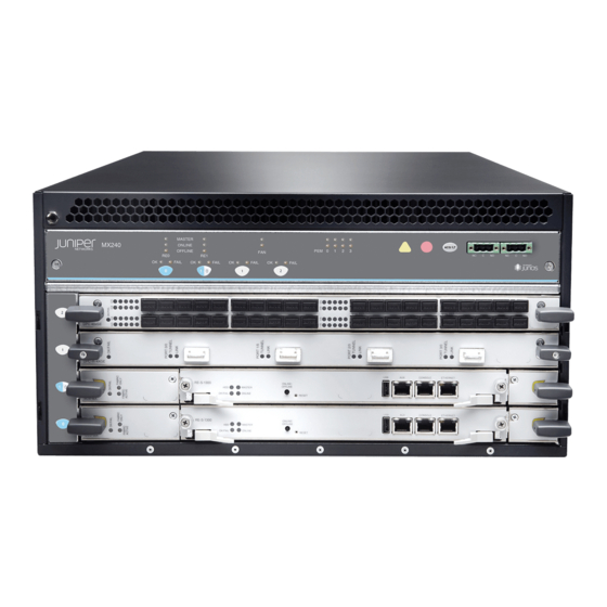
Page 34: Figure 1: Front View Of A Fully Configured Router Chassis
MX240 Ethernet Services Router Hardware Guide Figure 1: Front View of a Fully Configured Router Chassis Figure 2: Rear View of a Fully Configured AC-Powered Router Chassis (110 V) Router Chassis... -
Page 35: Figure 3: Rear View Of A Fully Configured Ac-Powered Router Chassis
Chapter 2: Hardware Components Figure 3: Rear View of a Fully Configured AC-Powered Router Chassis (220V) Figure 4: Rear View of a Fully Configured DC-Powered Router Chassis Router Chassis... - Page 36 MX240 Ethernet Services Router Hardware Guide Midplane The midplane is located toward the rear of the chassis and forms the rear of the DPC card cage (see Figure 5 on page 8). The DPCs and SCBs install into the midplane from the front of the chassis, and the power supplies install into the midplane from the rear of the chassis.
-
Page 37: Figure 6: Typical Dpcs Supported On The Mx240 Router
Figure 6 on page 9 shows typical DPCs supported on the MX240 router. For more information about DPCs, see the MX-series Ethernet Services Router DPC Guide. -
Page 38: Dpc Components
MX240 Ethernet Services Router Hardware Guide DPC Components Each DPC consists of the following components: DPC cover, which functions as a ground plane and a stiffener. Fabric interfaces. Two Gigabit Ethernet interfaces that allow control information, route information, and statistics to be sent between the Routing Engine and the CPU on the DPCs. -
Page 39: Host Subsystem
Chapter 2: Hardware Components Table 8: 40-Port Gigabit Ethernet DPC LEDs (continued) Label Color State Description Green On steadily Link is active. LINK No link. Two LEDs, located on the craft interface above the DPC, display the status of the DPC and are labeled FAIL . -
Page 40: Scb Slots
MX240 Ethernet Services Router Hardware Guide Figure 8: SCB SCB Slots You can install one or two SCBs. The SCBs install horizontally into the front of the chassis in the slots labeled (the multifunction slot can contain either SCB1 or DPC0). If any slots are empty, you must install a blank panel. -
Page 41: Scb Components
Chapter 2: Hardware Components SCB Components Each SCB consists of the following components: Chassis management Ethernet switch. I2C bus logic, used for low-level communication with each component. Component redundancy circuitry. Control Board/Routing Engine mastership mechanism. Gigabit Ethernet switch that is connected to the embedded CPU complex on all components. -
Page 42: Routing Engine
The Backup Routing Engine is hot-insertable and hot-removable. The MX240 router supports the RE-S-1300-2048 Routing Engine and the RE-S-2000-4096 Routing Engine. Both Routing Engines have the same ports and LEDs on the faceplate. -
Page 43: Figure 10: Usb Memory Device In A Routing Engine
Chapter 2: Hardware Components CPU—Runs JUNOS software to maintain the router's routing tables and routing protocols. It has a Pentium-class processor. DRAM—Provides storage for the routing and forwarding tables and for other Routing Engine processes. USB port—Provides a removable media interface through which you can install the JUNOS software manually. -
Page 44: Routing Engine Interface Ports
MX240 Ethernet Services Router Hardware Guide Table 10: Routing Engine LEDs Label Color State Description Blue On steadily Routing Engine is the Master. MASTER Green Green Hard disk is functioning normally. blinking Green Blinking Routing Engine is transitioning online. ONLINE On steadily Routing Engine is functioning normally. -
Page 45: Cable Management System
Chapter 2: Hardware Components Cable Management System The cable management system (see Figure 11 on page 17 and Figure 12 on page 17) consists of plastic dividers located on the left and right sides of each DPC, SCB, and multifunction slot. The cable management system allows you to route the cables outside the router and away from the DPCs, SCBs, and Routing Engines. -
Page 46: Figure 13: Front Panel Of The Craft Interface
MX240 Ethernet Services Router Hardware Guide SCB LEDs on page 20 Fan LEDs on page 20 Alarm Relay Contacts on page 21 Figure 13: Front Panel of the Craft Interface NOTE: At least one SCB must be installed in the router for the craft interface to obtain power. -
Page 47: Table 11: Alarm Leds And Alarm Cutoff/Lamp Test Button
Chapter 2: Hardware Components Table 11: Alarm LEDs and Alarm Cutoff/Lamp Test Button Shape Color State Description On steadily Critical alarm LED—Indicates a critical condition that can cause the router to stop functioning. Possible causes include component removal, failure, or overheating. Yellow On steadily Warning alarm LED—Indicates a serious but nonfatal... -
Page 48: Dpc Leds
MX240 Ethernet Services Router Hardware Guide DPC LEDs Each DPC has LEDs on the craft interface that indicate its status. The DPC LEDs, labeled , and shows status of either SCB1 or DPC0, depending on which component is installed in the slot), are located along the bottom of the craft interface. -
Page 49: Alarm Relay Contacts
Figure 14: Alarm Relay Contacts Power Supplies The MX240 router uses either AC or DC power supplies. You can configure the MX240 router with either one or two high-line (220 V) AC power supplies, two or four low-line (110 V) AC power supplies, or one or two DC power supplies. The power supplies... -
Page 50: Ac Power Supply Leds
This separate protective earthing terminal must be permanently connected to earth. In the high-line (220 V) AC power configuration, the MX240 router contains one or two AC power supplies, located horizontally at the rear of the chassis in slots... -
Page 51: Dc Power Supply
“Connecting Power to a DC-Powered Router” on page 56. For DC power electrical specifications, see “DC Power System Electrical Specifications” on page 167. DC Power Supply Configurations for the MX240 Router In the DC power configuration, the router contains either one or two DC power... -
Page 52: Dc Power Supply Leds
MX240 Ethernet Services Router Hardware Guide (left to right). You can upgrade your DC power system from one to two PEM2 power supplies. A single DC power supply provides power to all components. One DC power supply is required. A second DC power supply provides redundancy. -
Page 53: Figure 17: Airflow Through Chassis
Chapter 2: Hardware Components The air intake to cool the chassis is located on the side of the chassis next to the air filter. Air is pulled through the chassis toward the fan tray, where it is exhausted out the side of the system. The air intake to cool the power supplies is located in the front of the router above the craft interface. -
Page 54: Figure 19: Air Filter
MX240 Ethernet Services Router Hardware Guide Figure 19: Air Filter Cooling System... -
Page 55: Setting Up The Router
Part 2 Setting Up the Router Preparing the Site for Router Installation on page 29 Installation Overview on page 35 Unpacking the Router on page 37 Installing the Mounting Hardware on page 41 Installing the Router on page 45 Connecting the Router on page 49 Grounding and Providing Power to the Router on page 53 Configuring JUNOS Software on page 61 Setting Up the Router... -
Page 56: Setting Up The Router
MX240 Ethernet Services Router Hardware Guide Setting Up the Router... -
Page 57: Preparing The Site For Router Installation
Chapter 3 Preparing the Site for Router Installation This chapter describes how to prepare your site for installation of the MX240 router. It discusses the following topics: Site Preparation Checklist on page 29 Cabinet Requirements on page 30 Rack Requirements on page 31... -
Page 58: Cabinet Requirements
MX240 Ethernet Services Router Hardware Guide Table 19: Site Preparation Checklist (continued) Item or Task For More Information Performed By Date Calculate the optical power budget and optical “Calculating Power Budget for power margin. Fiber-Optic Cable” on page 181 Cabinet Requirements The router can be installed in a standard 482-mm wide (or larger) enclosed cabinet. -
Page 59: Rack Requirements
Cabinets, Racks, Panels, and Associated Equipment (document number EIA-310-D) published by the Electronics Industry Association. You can stack several MX240 routers in a rack that has sufficient usable vertical space. The rack must be strong enough to support the weight of the fully configured router, up to 128 lb (58.1 kg). -
Page 60: Connection To Building Structure
MX240 Ethernet Services Router Hardware Guide Figure 20: Typical Open-Frame Rack Spacing of Mounting Bracket Holes The router can be mounted in any rack that provides holes or hole patterns spaced at 1 U (1.75 in.) increments. The mounting brackets used to attach the chassis to a rack are designed to fasten to holes spaced at those distances. -
Page 61: Figure 21: Chassis Dimensions And Clearance Requirements
Chapter 3: Preparing the Site for Router Installation routers. Allow 2.8 in. (7 cm) between the side of the chassis and any non-heat-producing surface such as a wall. For service personnel to remove and install hardware components, there must be adequate space at the front and back of the router. At least 24 in. (61 cm) is required both in front of and behind the router. - Page 62 MX240 Ethernet Services Router Hardware Guide Clearance Requirements for Airflow and Hardware Maintenance...
-
Page 63: Installation Overview
Chapter 4 Installation Overview After you have prepared your installation site as described in “Preparing the Site for Router Installation” on page 29, you are ready to unpack and install the router. It is important to proceed through the installation process in the following order: Review the safety guidelines explained in “Safety and Regulatory Compliance Information”... - Page 64 MX240 Ethernet Services Router Hardware Guide...
-
Page 65: Chapter 5 Unpacking The Router
Chapter 5 Unpacking the Router This chapter describes how to prepare to install the router. It discusses the following topics: Tools and Parts Required on page 37 Unpacking the Router on page 37 Verifying Parts Received on page 38 Tools and Parts Required To unpack the router and prepare for installation, you need the following tools: Phillips (+) screwdriver, number 2 1/2-in. -
Page 66: Figure 22: Contents Of The Shipping Crate
MX240 Ethernet Services Router Hardware Guide To unpack the router (see Figure 22 on page 38): Move the shipping crate to a staging area as close to the installation site as possible, where you have enough room to remove the components from the chassis. -
Page 67: Figure 8: Scb
Chapter 5: Unpacking the Router If any part is missing, contact a customer service representative. A fully configured router contains the router chassis with installed components, listed in Table 20 on page 39, and an accessory box, which contains the parts listed in Table 21 on page 39. - Page 68 MX240 Ethernet Services Router Hardware Guide Table 21: Accessory Box Parts List (continued) Part Quantity Label, accessories contents, MX240 USB flash drive with JUNOS software Read me first document Affidavit for T1 connection Juniper Networks Product Warranty End User License Agreement Document sleeve 3 in.
-
Page 69: Installing The Mounting Hardware
Chapter 6 Installing the Mounting Hardware The router can be installed in a four-post rack or cabinet or an open-frame rack. Install the mounting hardware on the rack before installing the router. After the mounting hardware is installed, proceed to “Installing the Router” on page 45 or “Installing the Router Without a Mechanical Lift”... -
Page 70: Figure 23: Installing The Front Mounting Hardware For A Four-Post Rack Or Cabinet
MX240 Ethernet Services Router Hardware Guide To install the mounting shelf on the front rails of a four-post rack or cabinet, or the rails of an open-frame rack: If needed, install cage nuts in the holes specified in Table 22 on page 41. -
Page 71: Figure 24: Installing The Mounting Hardware For An Open-Frame Rack
Chapter 6: Installing the Mounting Hardware Figure 24: Installing the Mounting Hardware for an Open-Frame Rack Moving the Mounting Brackets for Center-Mounting the Router Two removable mounting brackets are attached to the mounting holes closest to the front of the chassis. You can move the pair of brackets to another position on the side of the chassis for center-mounting the router. - Page 72 MX240 Ethernet Services Router Hardware Guide Tighten the two screws completely. Repeat the procedure for the other bracket. Moving the Mounting Brackets for Center-Mounting the Router...
-
Page 73: Installing The Router
Chapter 7 Installing the Router This chapter discusses the following router installation topics: Safety Requirements, Warnings, and Guidelines on page 45 Installing the Router Using a Mechanical Lift on page 45 Safety Requirements, Warnings, and Guidelines To avoid harm to yourself or the router as you install and maintain it, follow the guidelines for working with and near electrical equipment, as well as the safety procedures for working with Internet routers. -
Page 74: Tools Required
MX240 Ethernet Services Router Hardware Guide Tools Required To install the router, you need the following tools: Mechanical lift Phillips (+) screwdriver, number 2 Installing the Router Using a Lift Before installing the router in the rack, read the safety information in “Chassis-Lifting Guidelines”... -
Page 75: Figure 25: Installing The Router In The Rack
Chapter 7: Installing the Router Figure 25: Installing the Router in the Rack NOTE: This illustration depicts the router being installed in an open-frame rack. For an illustration of the mounting hardware required for a four-post rack or cabinet, see Figure 23 on page 42. - Page 76 MX240 Ethernet Services Router Hardware Guide Installing the Router Using a Mechanical Lift...
-
Page 77: Chapter 8 Connecting The Router
Chapter 8 Connecting the Router Tools and Parts Required on page 49 Connecting the Router to Management and Alarm Devices on page 49 Connecting DPC Cables on page 51 Tools and Parts Required To connect the router to management devices and DPCs, you need the following tools and parts: Phillips (+) screwdrivers, numbers 1 and 2 2.5-mm flat-blade (–) screwdriver... -
Page 78: Connecting To A Network For Out-Of-Band Management
MX240 Ethernet Services Router Hardware Guide Figure 27: RJ-45 Cable Connector To connect external devices to the Routing Engine management ports, perform the procedures described in the following sections: Connecting to a Network for Out-of-Band Management on page 50 Connecting to a Management Console or Auxiliary Device on page 50... -
Page 79: Connecting Dpc Cables
Chapter 8: Connecting the Router system condition that triggers the red or yellow alarm LED on the craft interface also activates the corresponding alarm relay contact. The terminal blocks that plug into the alarm relay contacts are supplied with the router. -
Page 80: Figure 29: Attaching A Cable To A Dpc
MX240 Ethernet Services Router Hardware Guide CAUTION: Do not leave a fiber-optic transceiver uncovered except when inserting or removing cable. The safety cap keeps the port clean and prevents accidental exposure to laser light. Insert the cable connector into the cable connector port on the DPC faceplate. -
Page 81: Grounding And Providing Power To The Router
Chapter 9 Grounding and Providing Power to the Router Tools and Parts Required on page 53 Grounding the Router on page 54 Connecting Power to an AC-Powered Router on page 54 Powering On an AC-Powered Router on page 55 Connecting Power to a DC-Powered Router on page 56 Powering On a DC-Powered Router on page 58 Powering Off the Router on page 59 Tools and Parts Required... -
Page 82: Connecting Power To An Ac-Powered Router
MX240 Ethernet Services Router Hardware Guide Grounding the Router You ground the router by connecting a grounding cable to earth ground and then attaching it to the chassis grounding points using UNC 1/4-20 two screws. You must provide the grounding cables (the cable lugs are supplied with the router). For grounding cable specifications, see “Chassis Grounding Specifications”... -
Page 83: Powering On An Ac-Powered Router
Chapter 9: Grounding and Providing Power to the Router NOTE: Each power supply must be connected to a dedicated AC power feed and a dedicated external circuit breaker. We recommend that you use a 15 A (250 VAC) minimum, or as permitted by local code. Dress the power cord appropriately. -
Page 84: Connecting Power To A Dc-Powered Router
MX240 Ethernet Services Router Hardware Guide If any of the status LEDs indicates that the power supply is not functioning normally, repeat the installation and cabling procedures described in “Replacing Power System Components” on page 112. NOTE: After powering off a power supply, wait at least 60 seconds before turning it back on. - Page 85 Chapter 9: Grounding and Providing Power to the Router connected to chassis ground at the battery plant, you can use a multimeter to verify that the ohm output of the DC cables to chassis ground. . The cable with very large resistance (indicating an open circuit) to chassis ground will be and the cable with very low resistance (indicating a closed circuit) to chassis ground will be...
-
Page 86: Powering On A Dc-Powered Router
MX240 Ethernet Services Router Hardware Guide Figure 31: Connecting DC Power to the Router Powering On a DC-Powered Router WARNING: Before performing the following procedure, ensure that power is removed from the DC circuit. To ensure that all power is off, locate the circuit breaker on the panel board that services the DC circuit, switch the circuit breaker to the off position, and tape the switch handle of the circuit breaker in the off position. -
Page 87: Powering Off The Router
Chapter 9: Grounding and Providing Power to the Router Switch on the dedicated facility circuit breakers to provide power to the DC power cables. Check the LED is lit steadily green to verify that power is present. INPUT OK If power is not present: Verify that the fuse is installed correctly and turn on the breaker at the battery distribution fuse board or fuse bay. - Page 88 MX240 Ethernet Services Router Hardware Guide Wait until a message appears on the console confirming that the operating system has halted. For more information about the command, see the JUNOS System Basics and Services Command Reference. Attach an electrostatic discharge (ESD) grounding strap to your bare wrist and connect the strap to one of the ESD points on the chassis.
-
Page 89: Chapter 10 Configuring Junos Software
Chapter 10 Configuring JUNOS Software Configuring the JUNOS Software on page 61 Configuring the JUNOS Software The router is shipped with the JUNOS software preinstalled and ready to be configured when the router is powered on. There are three copies of the software: one on a CompactFlash card in the Routing Engine, one on a hard disk in the Routing Engine, and one on a USB flash drive that can be inserted into the slot in the Routing Engine faceplate. - Page 90 MX240 Ethernet Services Router Hardware Guide Start the CLI. root# cli root@> Enter configuration mode. cli> configure [edit] root@# Configure the name of the router. If the name includes spaces, enclose the name in quotation marks (“ ”). [edit] root@# set system host-name host-name Configure the router s domain name.
- Page 91 Chapter 10: Configuring JUNOS Software [edit] root@# set system root-authentication ssh-rsa public-key Optionally, display the configuration to verify that it is correct. [edit] root@# show system { host-name host-name; domain-name domain-name; backup-router address; root-authentication { authentication-method (password | public-key); name-server { address;...
- Page 92 MX240 Ethernet Services Router Hardware Guide Configuring the JUNOS Software...
-
Page 93: Hardware Maintenance, Troubleshooting, And Replacement Procedures
Part 3 Hardware Maintenance, Troubleshooting, and Replacement Procedures Maintaining Hardware Components on page 67 Troubleshooting Hardware Components on page 79 Replacing Hardware Components on page 87 Hardware Maintenance, Troubleshooting, and Replacement Procedures... -
Page 94: Procedures
MX240 Ethernet Services Router Hardware Guide Hardware Maintenance, Troubleshooting, and Replacement Procedures... -
Page 95: Maintaining Hardware Components
This chapter describes how to maintain hardware components installed in the router. Some components, such as the craft interface, require no maintenance. For information about returning a part to Juniper Networks for repair or replacement, see “Contacting Customer Support and Returning Hardware” on page 197. -
Page 96: Maintaining The Air Filter
MX240 Ethernet Services Router Hardware Guide few minutes without the air filter in place. For maintenance instructions, see “Maintaining the Air Filter” on page 68. Maintaining Cooling System Components This section discusses the following topics: Maintaining the Air Filter on page 68... - Page 97 Chapter 11: Maintaining Hardware Components Routing Engine 0 42 degrees C / 107 degrees F Routing Engine 1 Present CB 0 Intake 40 degrees C / 104 degrees F CB 0 Exhaust A 37 degrees C / 98 degrees F CB 0 Exhaust B 42 degrees C / 107 degrees F CB 0 ACBC...
-
Page 98: Maintaining The Host Subsystem
MX240 Ethernet Services Router Hardware Guide Maintaining the Host Subsystem The host subsystem comprises an SCB and a Routing Engine installed into a slot in the SCB. To maintain the host subsystem components, follow these guidelines: Check the LEDs on the craft interface to view information about the status of the Routing Engines. - Page 99 Chapter 11: Maintaining Hardware Components To check the status of the SCBs, issue the command. show chassis environment cb The output is similar to the following: user@host> show chassis environment cb CB 0 status: State Online Master Temperature 40 degrees C / 104 degrees F Power 1 1.2 V 1208 mV...
-
Page 100: Maintaining Packet Forwarding Engine Components
MX240 Ethernet Services Router Hardware Guide user@host> show chassis environment cb 0 CB 0 status: State Online Temperature Intake 66 degrees C / 150 degrees F Temperature Exhaust A 67 degrees C / 152 degrees F Temperature Exhaust B 73 degrees C / 163 degrees F Power 1.2 V... - Page 101 Chapter 11: Maintaining Hardware Components Empty Empty Online 1024 For more detailed output, add the option. The following example does not detail specify a slot number, which is optional: user@host> show chassis fpc detail Slot 1 information: State Online Temperature 33 degrees C / 91 degrees F Total CPU DRAM 1024 MB...
- Page 102 MX240 Ethernet Services Router Hardware Guide Maintaining DPC Cables To maintain DPCs and DPC cables, follow these guidelines: Use the cable management system (shown in Figure 11 on page 17) to support cables and prevent cables from dislodging or developing stress points.
-
Page 103: Holding A Dpc
Chapter 11: Maintaining Hardware Components CAUTION: Failure to handle DPCs as specified in this document can cause irreparable damage. This section discusses how to hold DPCs in both the vertical and horizontal positions. Regardless of orientation, this section uses the same terms for all four edges of the DPC (see Figure 32 on page 75): Faceplate—Edge of the DPC that has connectors into which you insert the SFP or XFP transceivers... -
Page 104: Figure 33: Do Not Grasp The Connector Edge
MX240 Ethernet Services Router Hardware Guide NOTE: A DPC weighs 13.1 lb (5.9 kg). Be prepared to accept the full weight of the DPC as you lift it. To hold a DPC vertically: Orient the DPC so that the faceplate faces you. To verify orientation, confirm that the text on the DPC is right-side up and the electromagnetic interference (EMI) strip is on the right-hand side. -
Page 105: Storing A Dpc
Chapter 11: Maintaining Hardware Components Never carry the DPC by the faceplate with only one hand. Do not rest any edge of a DPC directly against a hard surface (see Figure 34 on page 77). Do not stack DPCs. Figure 34: Do Not Rest the DPC on an Edge If you must rest the DPC temporarily on an edge while changing its orientation between vertical and horizontal, use your hand as a cushion between the edge and the surface. -
Page 106: Maintaining The Power Supplies
MX240 Ethernet Services Router Hardware Guide If you must insert the DPC into a bag by yourself, first lay the DPC horizontally on a flat, stable surface, sheet metal side down. Orient the DPC with the faceplate facing you. Carefully insert the DPC connector edge into the opening of the bag, and pull the bag toward you to cover the DPC. -
Page 107: Troubleshooting Hardware Components
Alarm Relay Contacts on page 80 LEDs on page 80 Juniper Networks Technical Assistance Center If you need assistance during troubleshooting, you can contact the Juniper Networks Technical Assistance Center (JTAC) by using the Web or by telephone. See “Requesting Technical Support” on page xxvii. -
Page 108: Leds
MX240 Ethernet Services Router Hardware Guide You enter CLI commands on one or more external management devices connected to ports on the Routing Engine. For more information about the Routing Engine ports, see “Routing Engine Interface Ports” on page 16. -
Page 109: Component Leds
Chapter 12: Troubleshooting Hardware Components Alarm LEDs—One large red circular LED and one large yellow triangular LED, located on the upper right of the craft interface, indicate two levels of alarm conditions. The circular red LED lights to indicate a critical condition that can result in a system shutdown. -
Page 110: Troubleshooting The Cooling System
MX240 Ethernet Services Router Hardware Guide RE might still be booting or the SCB is not receiving power. For more information, see “SCB Components” on page 13. RE LEDs—Four LEDs, labeled , and on each Routing MASTER ONLINE FAIL Engine faceplate indicate the status of the Routing Engine and hard disk drive. -
Page 111: Troubleshooting Dpcs
Chapter 12: Troubleshooting Hardware Components See “Maintaining Cooling System Components” on page 68. If the fans are not functioning normally, follow these guidelines to troubleshoot the fans: If the red alarm LED on the craft interface lights, use the CLI to get information about the source of an alarm condition: . -
Page 112: Troubleshooting The Power System
MX240 Ethernet Services Router Hardware Guide Total RLDRAM 256 MB Total DDR DRAM 4096 MB Start time: 2007-12-06 11:33:01 PST Uptime: 4 hours, 34 minutes, 48 seconds Slot 2 information: State Online Temperature 33 degrees C / 91 degrees F... - Page 113 Replace the power supply with a spare, as described in “Replacing Power System Components” on page 112. If you cannot determine the cause of the problem or need additional assistance, see “Juniper Networks Technical Assistance Center” on page 79. Troubleshooting the Power System...
- Page 114 MX240 Ethernet Services Router Hardware Guide Troubleshooting the Power System...
-
Page 115: Replacing Hardware Components
Table 23 on page 88 lists the FRUs for the MX240 router. Before you replace an SCB or a Routing Engine, you must take the host subsystem offline (see “Taking the Host Subsystem Offline”... -
Page 116: Table 23: Field-Replaceable Units
MX240 Ethernet Services Router Hardware Guide Table 23: Field-Replaceable Units Hot-Removable and Hot-Insertable FRUs Hot-Pluggable FRUs Air filter Master Switch Control Board (SCB) (if redundant) Craft interface Master Routing Engine (if redundant) Backup Switch Control Board (SCB) (if redundant) Switch Control Board (SCB) (nonredundant) -
Page 117: Removing The Craft Interface
Chapter 13: Replacing Hardware Components Table 24: Tools and Parts Required (continued) Tool or part Components Phillips (+) screwdrivers, numbers 1 Air filter and 2 Routing Engine Craft interface Cables and connectors Fan tray Rubber safety cap Wire cutters Cables and connectors DC power supply Replacing the Craft Interface The craft interface is located above the DPC card cage, as shown in... -
Page 118: Figure 36: Removing The Craft Interface
MX240 Ethernet Services Router Hardware Guide Grasp the craft interface faceplate and carefully tilt it toward you until it is horizontal. Disconnect the ribbon cable from the back of the faceplate by gently pressing on both sides of the latch with your thumb and forefinger. Remove the craft interface from the chassis. -
Page 119: Disconnecting The Alarm Relay Wires
Chapter 13: Replacing Hardware Components Figure 37: Installing a Craft Interface Replacing Alarm Relay Wires The alarm relay wires connect external alarm-reporting devices to the relay contacts on the craft interface. YELLOW The terminal blocks that plug into the alarm relay contacts are supplied with the router. -
Page 120: Connecting The Alarm Relay Wires
MX240 Ethernet Services Router Hardware Guide Connecting the Alarm Relay Wires To connect the alarm relay wires between a router and an alarm-reporting device (see Figure 38 on page 91): Prepare the required length of replacement wire with gauge between 28-AWG and 14-AWG (0.08 and 2.08 mm 2 ). -
Page 121: Figure 39: Removing The Fan Tray From An Mx240 Router
Place one hand under the fan tray to support it and pull the fan tray completely out of the chassis. Figure 39: Removing the Fan Tray from an MX240 Router Installing the Fan Tray To install the fan tray (see Figure 40 on page 94): Attach an electrostatic discharge (ESD) grounding strap to your bare wrist and connect the strap to one of the ESD points on the chassis. -
Page 122: Removing An Air Filter
MX240 Ethernet Services Router Hardware Guide Figure 40: Installing the Fan Tray in an MX240 Router Replacing the Air Filter The router has one air filter that installs vertically in the rear of the chassis. The air filter is hot-insertable and hot-removable. -
Page 123: Figure 41: Removing The Air Filter From An Mx240 Router
Loosen the captive screws on the air filter cover. Remove the air filter cover. Slide the air filter out of the chassis. Figure 41: Removing the Air Filter from an MX240 Router Installing the Air Filter To install the air filter (see Figure 42 on page 96): Attach an electrostatic discharge (ESD) grounding strap to your bare wrist and connect the strap to one of the ESD points on the chassis. -
Page 124: Replacing Host Subsystem Components
MX240 Ethernet Services Router Hardware Guide Figure 42: Installing the Air Filter in an MX240 Router Replacing Host Subsystem Components To replace a host subsystem, use the following procedures: Taking the Host Subsystem Offline on page 96 Replacing an SCB on page 97 Taking the Host Subsystem Offline The host subsystem is taken offline and brought online as a unit. - Page 125 Chapter 13: Replacing Hardware Components Determine whether the host subsystem is functioning as the master or as the backup, using one of the two following methods: Check the Routing Engine LEDs on the craft interface. If the green RE MASTER LED is lit, the corresponding host subsystem is functioning as the master.
-
Page 126: Operating And Positioning The Scb Ejectors
MX240 Ethernet Services Router Hardware Guide “Taking the Host Subsystem Offline” on page 96). To replace an SCB, use the following procedures: Operating and Positioning the SCB Ejectors on page 98 Removing an SCB on page 99 Installing an SCB on page 100... -
Page 127: Figure 43: Removing An Scb
Chapter 13: Replacing Hardware Components Removing an SCB To remove an SCB (see Figure 43 on page 99): NOTE: You can remove the SCB and Routing Engine as a unit, or remove the Routing Engine separately. Place an electrostatic bag or antistatic mat on a flat, stable surface. Attach an electrostatic discharge (ESD) grounding strap to your bare wrist and connect the strap to one of the ESD points on the chassis. - Page 128 MX240 Ethernet Services Router Hardware Guide Installing an SCB To install an SCB (see Figure 44 on page 102): Attach an electrostatic discharge (ESD) grounding strap to your bare wrist and connect the strap to one of the ESD points on the chassis. For more information about ESD, see “Preventing Electrostatic Discharge Damage”...
- Page 129 Chapter 13: Replacing Hardware Components To check the status of the SCB, use the CLI command: user@host> show chassis environment cb CB 0 status: State Online Master Temperature 25 degrees C / 77 degrees F Power 1 1.2 V 1198 mV 1.5 V 1508 mV 1.8 V...
-
Page 130: Replacing A Routing Engine
MX240 Ethernet Services Router Hardware Guide Figure 44: Installing an SCB Replacing a Routing Engine The router can have one or two Routing Engines. They are located in the front of the chassi within the SCBs in the horizontally along the bottom of the chassis in the slots marked . -
Page 131: Installing A Routing Engine
Chapter 13: Replacing Hardware Components NOTE: To maintain proper airflow through the chassis, do not leave an SCB installed in the chassis without a Routing Engine for extended periods of time. If a Routing Engine is removed, a replacement Routing Engine should be installed as soon as possible. -
Page 132: Replacing Connections To Routing Engine Interface Ports
MX240 Ethernet Services Router Hardware Guide user@host> show chassis routing-engine Routing Engine status: Slot 0: Current state Master For more information about using the CLI, see the JUNOS software manuals. Figure 46: Installing a Routing Engine Replacing Connections to Routing Engine Interface Ports You can connect the router to external management devices (see Figure 47 on page 104). -
Page 133: Removing The Management Ethernet Cable
Chapter 13: Replacing Hardware Components Replacing the Management Ethernet Cable To connect the Routing Engine to a network for out-of-band management, connect an Ethernet cable with RJ-45 connectors to the ETHERNET port on the Routing Engine. One such cable is provided with the router. For cable specifications, see “Routing Engine Interface Cable and Wire Specifications”... -
Page 134: Connecting The Cable To A Management Console Or Auxiliary Device
MX240 Ethernet Services Router Hardware Guide Connecting the Cable to a Management Console or Auxiliary Device To connect a serial cable to a management console or auxiliary device: Plug the RJ-45 end of the replacement serial cable into the CONSOLE port. - Page 135 Chapter 13: Replacing Hardware Components user@host>request chassis fpc slot slot-number offline For more information about the command, see the JUNOS System Basics and Services Command Reference. Disconnect the cables from the DPC. If the DPC uses fiber-optic cable, immediately cover each transceiver and the end of each cable with a rubber safety cap.
-
Page 136: Installing A Dpc
MX240 Ethernet Services Router Hardware Guide CAUTION: After removing a DPC from the chassis, wait at least 30 seconds before reinserting it, removing a DPC from a different slot, or inserting a DPC into a different slot. Figure 49: Removing a DPC... - Page 137 Chapter 13: Replacing Hardware Components Insert the appropriate cables into the cable connector ports on each DPC (see Figure 51 on page 110). Secure the cables so that they are not supporting their own weight. Place excess cable out of the way in a neatly coiled loop, using the cable management system.
-
Page 138: Removing An Sfp Or Xfp Transceiver
MX240 Ethernet Services Router Hardware Guide Figure 50: Installing a DPC Figure 51: Attaching a Cable to a DPC Removing an SFP or XFP Transceiver Small form-factor pluggable (SFPs) and XFPs are optical transceivers that are installed in a DPC. -
Page 139: Figure 52: Removing Sfps Or Xfps
Chapter 13: Replacing Hardware Components WARNING: Do not look directly into a fiber-optic transceiver or into the end of a fiber-optic cable. Fiber-optic transceivers contain laser light sources that can damage your eyes. Remove the cable connector plugged into the transceiver. Carefully drape the disconnected cable over the bobbins in the cable management system to prevent the cable from developing stress points. -
Page 140: Installing An Sfp Or Xfp Transceiver
MX240 Ethernet Services Router Hardware Guide Installing an SFP or XFP Transceiver To install an SFP or XFP: Attach an ESD wrist strap to your bare wrist and connect the wrist strap to one of the ESD points on the chassis. -
Page 141: Replacing An Ac Power Cord
Chapter 13: Replacing Hardware Components Replacing an AC Power Cord on page 118 Replacing a DC Power Supply Cable on page 119 Removing an AC Power Supply The power supplies are located at the rear of the chassis. Each AC power supply weighs approximately 5.0 lb (2.3 kg). -
Page 142: Figure 54: Installing An Ac Power Supply
MX240 Ethernet Services Router Hardware Guide Installing an AC Power Supply To install an AC power supply (see Figure 54 on page 114): Attach an electrostatic discharge (ESD) grounding strap to your bare wrist and connect the strap to one of the ESD points on the chassis. For more information about ESD, see “Preventing Electrostatic Discharge Damage”... - Page 143 Chapter 13: Replacing Hardware Components The power supplies are located at the rear of the chassis. Each DC power supply weighs approximately 3.8 lb (1.7 kg). CAUTION: Do not leave a power supply slot empty for more than 30 minutes while the router is operational.
-
Page 144: Figure 55: Removing A Dc Power Supply From An Mx240 Router
MX240 Ethernet Services Router Hardware Guide Figure 55: Removing a DC Power Supply from an MX240 Router Installing a DC Power Supply WARNING: Before performing the following procedure, ensure that power is removed from the DC circuit. To ensure that all power is off, locate the circuit breaker on the panel board that services the DC circuit, switch the circuit breaker to the off position, and tape the switch handle of the circuit breaker in the off position. - Page 145 DC power source at your site determines the color coding for the leads on the power cables that attach to the terminal studs on each power supply. NOTE: For the MX240 router, the DC power supply in PEM0 must be powered by...
-
Page 146: Disconnecting An Ac Power Cord
MX240 Ethernet Services Router Hardware Guide Figure 56: Installing a DC Power Supply in an MX240 Router Figure 57: Connecting DC Power to the Router Replacing an AC Power Cord To replace an AC power cord: Disconnecting an AC Power Cord on page 119... -
Page 147: Replacing A Dc Power Supply Cable
Chapter 13: Replacing Hardware Components Disconnecting an AC Power Cord WARNING: Before working on the router or near power supplies, unplug the power cord from an AC router. To disconnect the AC power cord: Unplug the power cord from the power source receptacle. Attach an electrostatic discharge (ESD) grounding strap to your bare wrist and connect the strap to one of the ESD points on the chassis. - Page 148 MX240 Ethernet Services Router Hardware Guide Disconnecting a DC Power Supply Cable To disconnect a power cable for a DC power supply: Switch the dedicated facility circuit breaker to the off position. Make sure that the voltage across the DC power source cable leads is 0 V and that there is no chance that the cables might become active during the removal process.
-
Page 149: Replacing The Cable Management System
Chapter 13: Replacing Hardware Components Figure 58: Connecting Power Cables to the DC Power Supply Replace the clear plastic cover over the terminal studs on the faceplate. Verify that the DC power cable is connected correctly, that it does not touch or block access to router components, and that it does not drape where people could trip on it. -
Page 150: Figure 59: Removing Or Installing The Cable Management System
MX240 Ethernet Services Router Hardware Guide Loosen the captive screws on either side of the chassis. Remove the cable manager. Figure 59: Removing or Installing the Cable Management System Installing the Cable Management System To install the cable management system (see Figure 59 on page 122): Position the cable management system on the front sides of the chassis. -
Page 151: Appendixes
Part 4 Appendixes Safety and Regulatory Compliance Information on page 125 Physical Specifications on page 161 Router Environmental Specifications on page 163 Power Guidelines, Requirements, and Specifications on page 165 Cable and Wire Guidelines and Specifications on page 179 Cable Connector Pinouts on page 185 Installing the Router Without a Mechanical Lift on page 187 Contacting Customer Support and Returning Hardware on page 197 Appendixes... - Page 152 MX240 Ethernet Services Router Hardware Guide Appendixes...
-
Page 153: Appendix A Safety And Regulatory Compliance Information
Appendix A Safety and Regulatory Compliance Information To install and use the router safely, follow proper safety procedures. This appendix discusses the following safety and regulatory compliance information: Definition of Safety Warning Levels on page 125 Safety Guidelines and Warnings on page 126 Agency Approvals and Compliance on page 155 Definition of Safety Warning Levels This manual uses the following three levels of safety warnings:... -
Page 154: General Safety Guidelines And Warnings
MX240 Ethernet Services Router Hardware Guide Attention Ce symbole d'avertissement indique un danger. Vous vous trouvez dans une situation pouvant causer des blessures ou des dommages corporels. Avant de travailler sur un équipement, soyez conscient des dangers posés par les circuits électriques et familiarisez-vous avec les procédures couramment utilisées pour éviter... -
Page 155: General Safety Guidelines And Warnings
Appendix A: Safety and Regulatory Compliance Information General Safety Guidelines and Warnings The following guidelines help ensure your safety and protect the router from damage. The list of guidelines might not address all potentially hazardous situations in your working environment, so be alert and exercise good judgment at all times. Perform only the procedures explicitly described in this manual. - Page 156 MX240 Ethernet Services Router Hardware Guide Waarschuwing Installatie en reparaties mogen uitsluitend door getraind en bevoegd personeel uitgevoerd worden. Varoitus Ainoastaan koulutettu ja pätevä henkilökunta saa asentaa tai vaihtaa tämän laitteen. Attention Tout installation ou remplacement de l'appareil doit être réalisé par du personnel qualifié...
- Page 157 Appendix A: Safety and Regulatory Compliance Information sécurité. L'accès aux zones de sécurité est sous le contrôle de l'autorité responsable de l'emplacement. Warnung Diese Einheit ist zur Installation in Bereichen mit beschränktem Zutritt vorgesehen. Ein Bereich mit beschränktem Zutritt ist ein Bereich, zu dem nur Wartungspersonal mit einem Spezialwerkzeugs, Schloß...
-
Page 158: Fire Safety Requirements
MX240 Ethernet Services Router Hardware Guide Preventing Electrostatic Discharge Damage Many router hardware components are sensitive to damage from static electricity. Some components can be impaired by voltages as low as 30 V. You can easily generate potentially damaging static voltages whenever you handle plastic or foam packing material or if you move components across plastic or carpets. -
Page 159: Fire Suppression
NOTE: To keep warranties effective, do not use a dry chemical fire extinguisher to control a fire at or near a Juniper Networks router. If a dry chemical fire extinguisher is used, the unit is no longer eligible for coverage under a service agreement. -
Page 160: Installation Instructions Warning
MX240 Ethernet Services Router Hardware Guide Chassis-Lifting Guidelines The weight of a fully configured chassis is about 128 lb (58.1 kg). Observe the following guidelines for lifting and moving the router: Before moving the router, read the guidelines in “Preparing the Site for Router Installation”... -
Page 161: Rack-Mounting Requirements And Warnings
De onderstaande richtlijnen worden verstrekt om uw veiligheid te verzekeren: De Juniper Networks router moet in een stellage worden geïnstalleerd die aan een bouwsel is verankerd. Dit toestel dient onderaan in het rek gemonteerd te worden als het toestel het enige in het rek is. - Page 162 Les directives ci-dessous sont destinées à assurer la protection du personnel: Le rack sur lequel est monté le Juniper Networks router doit être fixé à la structure du bâtiment. Si cette unité constitue la seule unité montée en casier, elle doit être placée dans le bas.
- Page 163 Para garantizar su seguridad, proceda según las siguientes instrucciones: El Juniper Networks router debe instalarse en un bastidor fijado a la estructura del edificio. Colocar el equipo en la parte inferior del bastidor, cuando sea la única unidad en el mismo.
-
Page 164: Ramp Warning
MX240 Ethernet Services Router Hardware Guide Juniper Networks router måste installeras i en ställning som är förankrad i byggnadens struktur. Om denna enhet är den enda enheten på ställningen skall den installeras längst ned på ställningen. Om denna enhet installeras på en delvis fylld ställning skall ställningen fyllas nedifrån och upp, med de tyngsta enheterna längst ned på... -
Page 165: Laser Beam Warning
Appendix A: Safety and Regulatory Compliance Information Laser Beam Warning on page 138 Radiation from Open Port Apertures Warning on page 139 General Laser Safety Guidelines When working around PICs, observe the following safety guidelines to prevent eye injury: Do not look into unterminated ports or at fibers that connect to unknown sources. Do not examine unterminated optical ports with optical instruments. - Page 166 MX240 Ethernet Services Router Hardware Guide Varoitus Luokan 1 valodiodituote. Attention Alarme de produit LED Class I. Warnung Class 1 LED-Produktwarnung. Avvertenza Avvertenza prodotto LED di Classe 1. Advarsel LED-produkt i klasse 1. Aviso Produto de classe 1 com LED.
-
Page 167: Maintenance And Operational Safety Guidelines And Warnings
Appendix A: Safety and Regulatory Compliance Information Radiation from Open Port Apertures Warning WARNING: Because invisible radiation might be emitted from the aperture of the port when no fiber cable is connected, avoid exposure to radiation and do not stare into open apertures. - Page 168 MX240 Ethernet Services Router Hardware Guide Operating Temperature Warning on page 142 Product Disposal Warning on page 143 Battery Handling Warning WARNING: Replacing the battery incorrectly might result in an explosion. Replace the battery only with the same or equivalent type recommended by the manufacturer.
- Page 169 Appendix A: Safety and Regulatory Compliance Information Jewelry Removal Warning WARNING: Before working on equipment that is connected to power lines, remove jewelry, including rings, necklaces, and watches. Metal objects heat up when connected to power and ground and can cause serious burns or weld the metal object to the terminals.
-
Page 170: Lightning Activity Warning
6 inches (15.2 cm) of clearance around the ventilation openings. Waarschuwing Om te voorkomen dat welke router van de Juniper Networks router dan ook oververhit raakt, dient u deze niet te bedienen op een plaats waar de maximale aanbevolen omgevingstemperatuur van 40 C wordt overschreden. -
Page 171: Product Disposal Warning
40 C. Para evitar a restrição à circulação de ar, deixe pelo menos um espaço de 15,2 cm à volta das aberturas de ventilação. ¡Atención! Para impedir que un encaminador de la serie Juniper Networks router se recaliente, no lo haga funcionar en un área en la que se supere la temperatura ambiente máxima recomendada de 40 C. -
Page 172: Electrical Safety Guidelines And Warnings
MX240 Ethernet Services Router Hardware Guide Waarschuwing Dit produkt dient volgens alle landelijke wetten en voorschriften te worden afgedankt. Varoitus Tämän tuotteen lopullisesta hävittämisestä tulee huolehtia kaikkia valtakunnallisia lakeja ja säännöksiä noudattaen. Attention La mise au rebut définitive de ce produit doit être effectuée conformément à... - Page 173 Appendix A: Safety and Regulatory Compliance Information General Electrical Safety Guidelines and Warnings Install the router in compliance with the following local, national, or international electrical codes: United States—National Fire Protection Association (NFPA 70), United States National Electrical Code. Canada—Canadian Electrical Code, Part 1, CSA C22.1. Other countries—International Electromechanical Commission (IEC) 60364, Part 1 through Part 7.
- Page 174 MX240 Ethernet Services Router Hardware Guide Avvertenza Questa apparecchiatura deve essere collegata a massa. Accertarsi che il dispositivo host sia collegato alla massa di terra durante il normale utilizzo. Advarsel Dette utstyret skal jordes. Forviss deg om vertsterminalen er jordet ved normalt bruk.
- Page 175 Appendix A: Safety and Regulatory Compliance Information Aviso Este dispositivo possui mais do que uma conexão de fonte de alimentação de energia; para poder remover a fonte de alimentação de energia, deverão ser desconectadas todas as conexões existentes. ¡Atención! Esta unidad tiene más de una conexión de suministros de alimentación; para eliminar la alimentación por completo, deben desconectarse completamente todas las conexiones.
- Page 176 MX240 Ethernet Services Router Hardware Guide Varning! Innan du arbetar med ett chassi eller nära strömförsörjningsenheter skall du för växelströmsenheter dra ur nätsladden och för likströmsenheter bryta strömmen vid överspänningsskyddet. TN Power Warning WARNING: The router is designed to work with TN power systems.
-
Page 177: Dc Power Electrical Safety Guidelines
Appendix A: Safety and Regulatory Compliance Information WARNING: The router is pluggable type A equipment installed in a restricted-access location. It has a separate protective earthing terminal (sized for UNC 1/4-20 ground lugs) provided on the chassis in addition to the grounding pin of the power supply cord. -
Page 178: Copper Conductors Warning
MX240 Ethernet Services Router Hardware Guide accordance with the National Electrical Code in the US and the Canadian Electrical Code in Canada. Run two wires from the circuit breaker box to a source of 48 VDC. Use appropriate gauge wire to handle up to 50 A. -
Page 179: Dc Power Disconnection Warning
Appendix A: Safety and Regulatory Compliance Information ¡Atención! Emplee sólo conductores de cobre. Varning! Använd endast ledare av koppar. DC Power Disconnection Warning WARNING: Before performing any of the following procedures, ensure that power is removed from the DC circuit. To ensure that all power is off, locate the circuit breaker on the panel board that services the DC circuit, switch the circuit breaker to position, and tape the switch handle of the circuit breaker in the position. -
Page 180: Dc Power Grounding Requirements And Warning
MX240 Ethernet Services Router Hardware Guide que toda a corrente foi DESLIGADA, localize o disjuntor no painel que serve o circuito de corrente contínua e coloque-o na posição OFF (Desligado), segurando nessa posição a manivela do interruptor do disjuntor com fita isoladora. -
Page 181: Dc Power Wiring Sequence Warning
Appendix A: Safety and Regulatory Compliance Information Aviso Ao instalar a unidade, a ligação à terra deverá ser sempre a primeira a ser ligada, e a última a ser desligada. ¡Atención! Al instalar el equipo, conectar la tierra la primera y desconectarla la última. Varning! Vid installation av enheten måste jordledningen alltid anslutas först och kopplas bort sist. -
Page 182: Dc Power Wiring Terminations Warning
MX240 Ethernet Services Router Hardware Guide Aviso Ate con alambre la fuente de potencia cc Usando los terminales apropiados en el extremo del cableado. Al conectar potencia, la secuencia apropiada del cableado se muele para moler, +RTN a +RTN, entonces -48 V a -48 V. Al desconectar potencia, la secuencia apropiada del cableado es -48 V a -48 V, +RTN a +RTN, entonces molió... -
Page 183: Agency Approvals And Compliance
Appendix A: Safety and Regulatory Compliance Information Avvertenza Quando occorre usare trecce, usare connettori omologati, come quelli a occhiello o a forcella con linguette rivolte verso l'alto. I connettori devono avere la misura adatta per il cablaggio e devono serrare sia l'isolante che il conduttore. Advarsel Hvis det er nødvendig med flertrådede ledninger, brukes godkjente ledningsavslutninger, som for eksempel lukket sløyfe eller spadetype med oppoverbøyde kabelsko. - Page 184 MX240 Ethernet Services Router Hardware Guide EN 60950-1 Safety of Information Technology Equipment AS/NZS 3548 Class A (Australia/New Zealand) EN55022 Class A (Europe) FCC Part 15 Class A (USA) VCCI Class A (Japan) Immunity EN-61000-3-2 Power Line Harmonics EN-61000-3-3 Voltage Fluctuations and Flicker...
-
Page 185: Canada
Appendix A: Safety and Regulatory Compliance Information Compliance Statements for EMC Requirements Canada This Class A digital apparatus complies with Canadian ICES-003. Cet appareil numérique de la classe A est conforme à la norme NMB-003 du Canada. European Community This is a Class A product. In a domestic environment this product might cause radio interference in which case the user might be required to take adequate measures. -
Page 186: Japan
MX240 Ethernet Services Router Hardware Guide Declaration of Conformity Japan Agency Approvals and Compliance... -
Page 187: United States
Appendix A: Safety and Regulatory Compliance Information Translation: This is a Class A product. In a domestic environment this product might cause radio interference in which case the user might be required to take adequate measures. VCCI-A United States The router has been tested and found to comply with the limits for a Class A digital device, pursuant to Part 15 of the FCC Rules. - Page 188 MX240 Ethernet Services Router Hardware Guide Agency Approvals and Compliance...
-
Page 189: Appendix B Physical Specifications
Appendix B Physical Specifications Physical Specifications on page 161 Physical Specifications Table 25 on page 161 summarizes the physical specifications for the router chassis. Table 25: Physical Specifications Description Value Chassis dimensions 8.71 in. (22.1 cm) high 17.45 in. (44.3 cm) wide 24.5 in. - Page 190 MX240 Ethernet Services Router Hardware Guide Physical Specifications...
-
Page 191: Appendix C Router Environmental Specifications
Appendix C Router Environmental Specifications Router Environmental Specifications on page 163 Router Environmental Specifications Table 26 on page 163 specifies the environmental specifications required for normal router operation. In addition, the site should be as dust-free as possible. For more information, see “Maintaining Hardware Components”... - Page 192 MX240 Ethernet Services Router Hardware Guide Router Environmental Specifications...
-
Page 193: Appendix D Power Guidelines, Requirements, And Specifications
Appendix D Power Guidelines, Requirements, and Specifications Chassis Grounding Specifications on page 165 DC Power Specifications and Requirements on page 166 AC Power Specifications and Requirements on page 171 Site Electrical Wiring Guidelines on page 176 Chassis Grounding Specifications To meet safety and electromagnetic interference (EMI) requirements and to ensure proper operation, the router must be adequately grounded before power is connected. -
Page 194: Grouding Cable Specification
MX240 Ethernet Services Router Hardware Guide Figure 61: Grounding Cable Lug CAUTION: Before router installation begins, a licensed electrician must attach a cable lug to the grounding and power cables that you supply. A cable with an incorrectly attached lug can damage the router. -
Page 195: Table 28: Dc Power System Electrical Specifications
Appendix D: Power Guidelines, Requirements, and Specifications DC Power System Electrical Specifications Table 28 on page 167 lists the DC power system electrical specifications. Table 28: DC Power System Electrical Specifications Item Specification DC input voltage Operating range: –40.5 to –72 VDC DC system current rating 31 A @ –48 VDC per input (maximum) DC system input power... -
Page 196: Table 30: Dc-Powered Base Router Power Requirements
MX240 Ethernet Services Router Hardware Guide power supply configurations. The base DC-powered router includes the midplane, craft interface, and fan tray running at normal speed. Table 30: DC-Powered Base Router Power Requirements Current Power Requirement Requirement (Amps @ DC Power Supply Configuration (Watts) –48 VDC) - Page 197 Appendix D: Power Guidelines, Requirements, and Specifications 1.38 A + 0.4 A + 3.1 A + 1.9 A + 3(7.6 A) = 1.38 A + 0.4 A + 3.1 A + 1.9 A + 22.8 A = 29.58 A @ 48 VDC = 1,420 W DC Input current from a DC source other than –48 VDC (based on maximum configuration;...
-
Page 198: Figure 62: Typical Dc Source Cabling To The Router
MX240 Ethernet Services Router Hardware Guide DC Power Cable Specifications Figure 62 on page 170 shows a typical DC source cabling arrangement. Figure 62: Typical DC Source Cabling to the Router The DC power supply in must be powered by dedicated power feeds derived... -
Page 199: Dc Power Cable Lug Specifications
Appendix D: Power Guidelines, Requirements, and Specifications DC Power Cable Lug Specifications The accessory box shipped with the router includes the cable lugs that attach to the terminal studs of each power supply (see Figure 63 on page 171). Figure 63: DC Power Cable Lug CAUTION: Before router installation begins, a licensed electrician must attach a cable lug to the grounding and power cables that you supply. -
Page 200: Ac Power System Electrical Specifications
MX240 Ethernet Services Router Hardware Guide AC Power Specifications AC Power System Electrical Specifications on page 172 AC Power Supply Electrical Specifications on page 172 AC Power System Electrical Specifications Table 33 on page 172 lists the AC power system electrical specifications. -
Page 201: Table 35: Ac Base Router Power Requirements
Appendix D: Power Guidelines, Requirements, and Specifications For AC-powered routers, you can use the information in Table 35 on page 173 and Table 36 on page 173 to calculate the power consumption and thermal output for your hardware configuration. Table 35 on page 173 lists the power requirements for base AC-powered routers operating under typical voltage conditions and includes various power supply configurations. -
Page 202: Ac Power Circuit Breaker Specifications
MX240 Ethernet Services Router Hardware Guide Base router (with fan tray at normal speed and two power supplies) + 1 SCB + 1 Routing Engine + 1 DPC = 270 W + 176 W + 106 W + 367 W = 919 W... -
Page 203: Figure 64: Ac Plug Types
Appendix D: Power Guidelines, Requirements, and Specifications Table 37 on page 175 provides specifications and Figure 64 on page 175 depicts the plug on the AC power cord provided for each country or region. Table 37: AC Power Cord Specifications Country Model Number Electrical Specification... -
Page 204: Site Electrical Wiring Guidelines
MX240 Ethernet Services Router Hardware Guide NOTE: In North America, AC power cords must not exceed 4.5 m (approximately 14.75 ft) in length, to comply with National Electrical Code (NEC) Sections 400-8 (NFPA 75, 5-2.2) and 210-52, and Canadian Electrical Code (CEC) Section 4-010(3). - Page 205 Appendix D: Power Guidelines, Requirements, and Specifications advice. Strong sources of electromagnetic interference (EMI) can destroy the signal drivers and receivers in the router and conduct power surges over the lines into the equipment, resulting in an electrical hazard. It is particularly important to provide a properly grounded and shielded environment and to use electrical surge-suppression devices.
- Page 206 MX240 Ethernet Services Router Hardware Guide Site Electrical Wiring Guidelines...
-
Page 207: Appendix E Cable And Wire Guidelines And Specifications
Appendix E Cable and Wire Guidelines and Specifications To prepare for router or component installation, ensure that you have all required cables and wires. Network Cable Specifications and Guidelines on page 179 Routing Engine Interface Cable and Wire Specifications on page 183 Network Cable Specifications and Guidelines The various PICs supported on the router accept different kinds of network cable, including multimode and single-mode fiber-optic cable. - Page 208 For information about the maximum transmission distance and supported wavelength range for the types of single-mode and multimode fiber-optic cable used by DPCs on the MX240 router, see the MX-series Ethernet Services Router DPC Guide. Exceeding the maximum transmission distances can result in significant signal loss, which causes unreliable transmission.
-
Page 209: Table 38: Estimated Values For Factors Causing Link Loss
Appendix E: Cable and Wire Guidelines and Specifications Calculating Power Budget for Fiber-Optic Cable To ensure that fiber-optic connections have sufficient power for correct operation, calculate the link's power budget, which is the maximum amount of power it can transmit. When you calculate the power budget, you use a worst-case analysis to provide a margin of error, even though all the parts of an actual system do not operate at the worst-case levels. - Page 210 MX240 Ethernet Services Router Hardware Guide Table 38: Estimated Values for Factors Causing Link Loss (continued) Link-Loss Factor Estimated Link-Loss Value Splice 0.5 dB Fiber attenuation Single-mode—0.5 dB/km Multimode—1 dB/km The following example uses the estimated values in Table 38 on page 181 to calculate...
-
Page 211: Table 39: Cable And Wire Specifications For Routing Engine Management And Alarm Interfaces
Appendix E: Cable and Wire Guidelines and Specifications Routing Engine Interface Cable and Wire Specifications Table 39 on page 183 lists the specifications for the cables that connect to management ports and the wires that connect to the alarm relay contacts. Table 39: Cable and Wire Specifications for Routing Engine Management and Alarm Interfaces Cable... - Page 212 MX240 Ethernet Services Router Hardware Guide Routing Engine Interface Cable and Wire Specifications...
-
Page 213: Appendix F Cable Connector Pinouts
Appendix F Cable Connector Pinouts This appendix describes the pinouts for the following cable connectors: RJ-45 Connector Pinouts for the Routing Engine ETHERNET Port on page 185 RJ-45 Connector Pinouts for the Routing Engine AUX and CONSOLE Ports on page 185 RJ-45 Connector Pinouts for the Routing Engine ETHERNET Port The port on the craft interface labeled ETHERNET is an autosensing 10/100-Mbps Ethernet RJ-45 receptacle that accepts an Ethernet cable for connecting the Routing... - Page 214 MX240 Ethernet Services Router Hardware Guide an auxiliary or console management device. For more information, see “Routing Engine Interface Ports” on page 16. Table 41 on page 186 describes the RJ-45 connector pinout. Table 41: RJ-45 Connector Pinout for the AUX and CONSOLE Ports...
-
Page 215: Appendix G Installing The Router Without A Mechanical Lift
Appendix G Installing the Router Without a Mechanical Lift If you cannot use a mechanical lift to install the router (the preferred method), you can install it manually. Before installing the router manually, you must first remove components from the chassis, and you must reinstall the components once the router is installed in the rack. -
Page 216: Removing The Power Supplies
MX240 Ethernet Services Router Hardware Guide how to remove components from the chassis, first from the rear and then from the front: Removing the Power Supplies on page 188 Removing the Fan Tray on page 189 Removing SCBs on page 189... -
Page 217: Removing The Fan Tray
Appendix G: Installing the Router Without a Mechanical Lift Removing the Fan Tray In the rear of the chassis, the fan tray is located on the right of the chassis. The fan tray weighs about 4.2 lb (1.9 kg). To remove the fan tray (see Figure 66 on page 189 ): Attach an electrostatic discharge (ESD) grounding strap to your bare wrist and connect the strap to one of the ESD points on the chassis. -
Page 218: Removing Dpcs
MX240 Ethernet Services Router Hardware Guide Simultaneously rotate the ejector handles counterclockwise to unseat the SCB. Grasp the ejector handles and slide the SCB about halfway out of the chassis. Place one hand underneath the SCB to support it and slide it completely out of the chassis. -
Page 219: Figure 68: Removing A Dpc
Appendix G: Installing the Router Without a Mechanical Lift CAUTION: The weight of the DPC is concentrated in the back end. Be prepared to accept the full weight—up to 13.1 lb (5.9 kg)—as you slide the DPC out of the chassis. When the DPC is out of the chassis, do not hold it by the ejector handles, bus bars, or edge connectors. -
Page 220: Installing The Chassis In The Rack Manually
MX240 Ethernet Services Router Hardware Guide Installing the Chassis in the Rack Manually To install the router in the rack (see Figure 69 on page 193): CAUTION: If you are installing more than one router in a rack, install the lowest one first. -
Page 221: Reinstalling Components In The Chassis
Appendix G: Installing the Router Without a Mechanical Lift Figure 69: Installing the Router in the Rack NOTE: This illustration depicts the router being installed in an open-frame rack. For an illustration of the mounting hardware required for a four-post rack or cabinet, see Figure 23 on page 42. -
Page 222: Figure 70: Reinstalling A Power Supply
MX240 Ethernet Services Router Hardware Guide Attach an electrostatic discharge (ESD) grounding strap to your bare wrist and connect the strap to one of the ESD points on the chassis. For more information about ESD, see “Preventing Electrostatic Discharge Damage” on page 130. -
Page 223: Reinstalling Scbs
Appendix G: Installing the Router Without a Mechanical Lift Figure 71: Installing a Fan Tray Reinstalling SCBs To reinstall an SCB (see Figure 72 on page 196): CAUTION: Before removing or replacing an SCB, ensure that the ejector handles are stored vertically and pressed toward the center of the SCB. -
Page 224: Reinstalling Dpcs
MX240 Ethernet Services Router Hardware Guide Figure 72: Installing an SCB Reinstalling DPCs To reinstall a DPC (see Figure 73 on page 196): Attach an electrostatic discharge (ESD) grounding strap to your bare wrist and connect the strap to one of the ESD points on the chassis. For more information about ESD, see “Preventing Electrostatic Discharge Damage”... -
Page 225: Appendix H Contacting Customer Support And Returning Hardware
Appendix H Contacting Customer Support and Returning Hardware This appendix describes how to return the router or individual components to Juniper Networks for repair or replacement: Locating Component Serial Numbers on page 197 Contacting Customer Support on page 202 Return Procedure on page 203... -
Page 226: Mx240 Chassis Serial Number Label
Figure 74: Serial Number ID Label The following sections describe the label location on each type of component: MX240 Chassis Serial Number Label on page 198 SCB Serial Number Label on page 199 DPC Serial Number Label on page 200... -
Page 227: Figure 75: Mx240 Chassis Serial Number Label
Appendix H: Contacting Customer Support and Returning Hardware Figure 75: MX240 Chassis Serial Number Label SCB Serial Number Label The serial number is located on the right side of the top of the SCB (see Figure 76 on page 199). -
Page 228: Figure 77: Dpc Serial Number Label
MX240 Ethernet Services Router Hardware Guide DPC Serial Number Label The serial number label is located on the center of the right side of the DPC (see Figure 77 on page 200). Figure 77: DPC Serial Number Label Power Supply Serial Number Labels The serial number label is located on the top of the AC power supply (see Figure 78 on page 201). -
Page 229: Figure 78: Ac Power Supply Serial Number Label
Appendix H: Contacting Customer Support and Returning Hardware Figure 78: AC Power Supply Serial Number Label Figure 79: DC Power Supply Serial Number Label Routing Engine Serial Number Label The serial number label is located on the right side of the top of the Routing Engine (see Figure 80 on page 202). -
Page 230: Contacting Customer Support
Contacting Customer Support After you have located the serial numbers of the components you need to return, contact Juniper Networks Technical Assistance Center (JTAC) in one of the following ways. You can contact JTAC 24 hours a day, seven days a week: On the Web, using the Case Manager link at: http://www.juniper.net/support/... -
Page 231: Return Procedure
NOTE: Do not return any component to Juniper Networks, Inc. unless you have first obtained an RMA number. Juniper Networks, Inc. reserves the right to refuse shipments that do not have an RMA. -
Page 232: Tools And Parts Required
To pack the router for shipment: Retrieve the shipping crate and packing materials in which the router was originally shipped. If you do not have these materials, contact your Juniper Networks representative about approved packaging materials. Attach an electrostatic discharge (ESD) grounding strap to your bare wrist and connect the strap to one of the ESD points on the chassis. -
Page 233: Packing Components For Shipment
Appendix H: Contacting Customer Support and Returning Hardware Remove the cables that connect to all external devices. For instructions, see “Replacing Connections to Routing Engine Interface Ports” on page 104. Remove all field replaceable units (FRUs) from the router. Remove the router from the rack: If you are using a mechanical lift, place the lift platform under the router, unscrew and remove the mounting screws from the rack, and move the router to the shipping crate. - Page 234 MX240 Ethernet Services Router Hardware Guide Packing Components for Shipment...
-
Page 235: Part 5 Index
Part 5 Index Index on page 209 Index... - Page 236 MX240 Ethernet Services Router Hardware Guide Index...
- Page 237 Index ATM analyzer, use of............74 attenuation in fiber-optic cable........180 Symbols AUX port See auxiliary port #, comments in configuration statements....xix auxiliary port ( ), in syntax descriptions..........xix description............16 < >, in syntax descriptions........xix auxiliary port (for Routing Engine management) [ ], in configuration statements........xix cable { }, in configuration statements........xix connection during initial installation....50...
- Page 238 MX240 Ethernet Services Router Hardware Guide grounding See DC power and grounding cables configuration power See AC power cord router..............61 cable management system console port description............17 description............16 fiber-optic cable, use with........74 CONSOLE port See console port installation............122 console port (for Routing Engine management) removal..............121...
- Page 239 Index replacing.............106 status, checking........72, 74, 83 grounding (electrical) specifications DPCs AC-powered router..........165 components............10 DC-powered router..........165 troubleshooting.............83 grounding cables lug..............165 earthquakes site preparation for..........32 hardware components tested toleration for seismic........163 power requirements...........171 EIA rack standards............31 returning for repair or replacement....197 electrical specifications........167, 172 higher-order mode loss (HOL)........179 electricity host subsystem...
- Page 240 MX240 Ethernet Services Router Hardware Guide maintenance See maintenance guidelines modal dispersion in fiber-optic cable......180 DPC...............74 mode loss, higher-order..........179 packing multimode fiber-optic cable See cable, fiber-optic router for shipment........204 interface network See DPC interference NEBS standards............155 electromagnetic..........176 network cable See cable, fiber-optic; cable, DPC radio frequency...........176...
- Page 241 Index powering on the router..........55, 58 pinouts for cable connections......185 ports..............16 description.............16 See also auxiliary port, console port, Ethernet rack port clearance around, required........32 replacing.............102 mounting bracket hole spacing......32 status indicator lights..........14 securing to building..........32 taking offline............96 size and strength required........31 USB port...............14 standards, EIA and ETSI........31 rack mounting...
- Page 242 MX240 Ethernet Services Router Hardware Guide specifications AC power cord............174 U (rack unit)..............31 cable..............179 unpacking the router............37 power............170 Routing Engine management ports....183 See also cable, DPC clearance around rack...........32 warnings electrical.............174 electrical.............144 cable and wiring..........176 general..............127 environmental............163 installation............131 fire safety............130 laser and LED.............136...
Need help?
Do you have a question about the MX240 and is the answer not in the manual?
Questions and answers