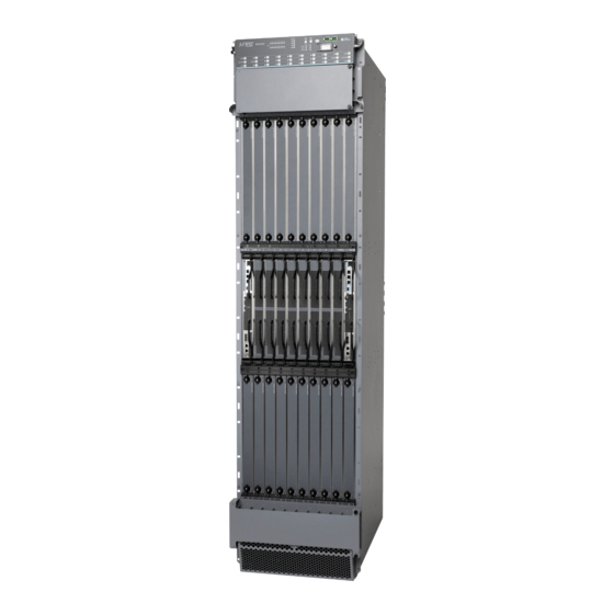
Sign In
Upload
Manuals
Brands
Juniper Manuals
Network Router
MX2020
Juniper MX2020 Manuals
Manuals and User Guides for Juniper MX2020. We have
4
Juniper MX2020 manuals available for free PDF download: Hardware Manual, Quick Start Manual
Juniper MX2020 Hardware Manual (630 pages)
3D Universal Edge Router
Brand:
Juniper
| Category:
Network Router
| Size: 33.14 MB
Table of Contents
Table of Contents
3
About the Documentation
27
Documentation and Release Notes
27
Supported Platforms
27
Documentation Conventions
27
Table 1: Notice Icons
28
Table 2: Text and Syntax Conventions
28
Documentation Feedback
29
About the Documentation
29
Requesting Technical Support
30
Opening a Case with JTAC
30
Self-Help Online Tools and Resources
30
Overview
33
System Overview and Architecture
33
Chassis
33
Host Subsystem Components
33
Power Subsystem
33
Chapter 1 MX2020 Router Overview
35
Chapter 2 System Overview and Architecture
37
MX2020 Chassis Description
37
Figure 1: Front View of a Fully Configured MX2020 Router Chassis
38
Table 3: Front Components in a Fully Configured MX2020 Router
38
System Overview and Architecture
39
Figure 2: Rear View of a Fully Configured AC-Powered MX2020 Router
40
Chassis
40
Table 4: Rear Components in a Fully Configured AC-Powered MX2020
40
Figure 3: Rear View of a Fully Configured DC-Powered MX2020 Router
41
Table 5: Rear Components in a Fully Configured DC-Powered MX2020
42
MX2020 Backplane Description
43
Figure 4: MX2020 Router ESD Points
43
MX2020 Component Redundancy
44
Figure 5: Power Distribution from each Power Subsystem to the Frus
45
Figure 6: DC Power Subsystem Feed Redundancy
45
Figure 7: Power Distribution from Three-Phase Feed Delta PDM to the AC
46
Psms
46
Figure 8: Power Distribution from Three-Phase Feed Wye PDM to the AC
46
Table 6: AC PDM Delta and Wye Current Requirements
47
MX2020 Field-Replaceable Units
48
MX2020 Router Hardware Components and CLI Terminology
49
Table 7: Field-Replaceable Units
49
Table 8: MX2020 Router Hardware Components and CLI Terminology
49
Chapter 3 Chassis Components and Descriptions
53
MX2020 Chassis Description
53
Figure 9: Front View of a Fully Configured MX2020 Router Chassis
54
Table 9: Front Components in a Fully Configured MX2020 Router
54
Chassis Components and Descriptions
55
Figure 10: Rear View of a Fully Configured AC-Powered MX2020 Router
56
Chassis
56
Table 10: Rear Components in a Fully Configured AC-Powered MX2020
56
Figure 11: Rear View of a Fully Configured DC-Powered MX2020 Router Chassis
57
Table 11: Rear Components in a Fully Configured DC-Powered MX2020
58
MX2020 Backplane Description
59
Figure 12: MX2020 Router ESD Points
59
MX2020 Component Redundancy
60
Figure 13: Power Distribution from each Power Subsystem to the Frus
61
Figure 14: DC Power Subsystem Feed Redundancy
61
Figure 16: Power Distribution from Three-Phase Feed Wye PDM to the AC
62
Table 12: AC PDM Delta and Wye Current Requirements
63
MX2020 Field-Replaceable Units
64
MX2020 Router Hardware Components and CLI Terminology
65
Table 13: Field-Replaceable Units
65
Table 14: MX2020 Router Hardware Components and CLI Terminology
65
Chapter 4 Alarm and Display Components
69
MX2020 Craft Interface Description
69
Figure 17: Front Panel of the Craft Interface
69
Figure 18: Extended Craft Interface
70
Table 15: Craft Interface Leds, Buttons, and Connectors
70
MX2020 Component Leds on the Craft Interface
71
MX2020 Host Subsystem Leds and Buttons on the Craft Interface
71
Table 16: Host Subsystem Leds on the Craft Interface
71
MX2020 Power Supply Module Leds on the Craft Interface
72
MX2020 Line Card Leds and Buttons on the Craft Interface
72
MX2020 SFB LED and Buttons on the Craft Interface
72
Table 17: Power Supply Module Leds on the Craft Interface
72
Table 18: Line Card Leds on the Craft Interface
72
MX2020 Fan Tray Leds on the Craft Interface
73
MX2020 Alarm Relay Contacts on the Craft Interface
73
Alarm and Display Components
73
Table 19: SFB LED on the Craft Interface
73
Table 20: Fan Tray Leds on the Craft Interface
73
MX2020 Alarm Leds and Alarm Cutoff/Lamp Test Button
74
Figure 19: Alarm Relay Contacts
74
Table 21: Alarm Relay Contacts
74
Table 22: Alarm Leds and Alarm Cutoff/Lamp Test Button
75
Chapter 5 Cable and Rack Management
77
MX2020 Cable Manager Description
77
Standard Cable Management System
77
Figure 20: MX2020 Standard Cable Managers
78
Figure 21: Upper and Lower Cable Management
79
Extended Cable Management System
80
Figure 22: Middle Card-Cage Cable Manager
80
Figure 23: Middle Card-Cage Air Filter
80
Figure 24: MX2020 Extended Cable Managers
81
MX2020 Rack-Mounting Hardware
82
Figure 25: Upper and Lower Extended Cable Management
82
Chapter 6 Cooling System
85
Cooling System
85
MX2020 Cooling System Description
85
Figure 26: Removing Fan Tray
85
Figure 27: Airflow through the Chassis
86
Cooling System
87
Figure 28: Upper/Lower Fan Tray
87
Figure 29: Lower Fan Tray Air Filter
87
MX2020 Fan Tray LED
88
Table 23: Fan Tray Leds
88
Chapter 7 Host Subsystem Components
89
MX2020 Host Subsystem Description
89
Supported CB-RE
90
CB-RE Function
90
CB-RE Slots
90
CB-RE Interface Ports
90
MX2020 CB-RE Description
91
Figure 30: RE-MX2000-1800X4 CB-RE Front View
91
Table 24: Components on the RE-MX2000-1800X4
91
RE-MX2000-1800X4 CB-RE Description
93
RE-MX2000-1800X4 CB-RE Components
93
RE-MX2000-1800X4 CB-RE Boot Sequence
94
MX2020 CB-RE Leds
94
Table 25: CB-RE Leds
95
MX2020 Switch Fabric Board Description
96
SFB Slots
96
SFB Redundancy
96
SFB Components
96
Figure 31: SFB
96
MX2020 Switch Fabric Board LED
97
Table 26: Switch Fabric Board LED
97
Chapter 8 Interface Modules—Adcs, Mpcs, and Mics
99
MX2020 Modular Port Concentrator Description
100
Figure 32: Typical ADC Supported on the MX2020 Router
100
Figure 33: Typical MPC Supported on the MX2020 Router
101
Figure 34: MPC Installed in the MX2020 Router
101
Interface Modules-Adcs, Mpcs, and Mics
101
MPC Components
101
MX2020 Modular Port Concentrator Leds
102
Routers
104
Table 27: Mpcs Supported by MX240, MX480, MX960, MX2010, and MX2020
104
MX2020 MPC Terminology
105
MX2020 Modular Interface Card Description
105
Figure 35: MPC Edges
105
Mics Supported by MX Series Routers
106
Routers
106
Table 28: Mics Supported by MX240, MX480, MX960, MX2010, and MX2020
107
Routers
107
Table 29: Mics Supported by MX5, MX10, MX40, MX80, and MX104 Routers
108
MX2020 Modular Interface Card Leds
110
MX2020 Port and Interface Numbering
111
Figure 36: MX2020 Interface Port Mapping
112
Interface Modules-Adcs, Mpcs, and Mics
99
MX2020 Adapter Card (ADC) Description
99
Chapter 9 Power Subsystem
115
MX2020 Power Midplane Description
117
Table 30: Supported MX2020 Power System Components
117
MX2020 Three-Phase Delta AC Power Distribution Module Description
118
Figure 37: Three-Phase Delta AC Power Distribution Module
118
Figure 38: Three-Phase Delta AC Power Distribution Module Connections
119
Figure 39: Three-Phase Delta AC Power Cord
119
MX2020 Three-Phase Wye AC Power Distribution Module Description
120
Figure 40: Three-Phase Wye AC Power Distribution Module
120
Figure 41: Three-Phase Wye AC Power Distribution Module Connections
121
Figure 42: Three-Phase Wye AC Power Cord
121
Description
122
MX2010 DC Power Distribution Module Description
122
Figure 43: Seven Feed Single Phase AC Power Distribution Module
122
MX2020 Three-Phase Delta and Wye AC Power Distribution Module Leds
123
Figure 44: DC Power Distribution Module
123
Power Subsystem
115
MX2020 Power Subsystem Description
115
Figure 45: Three-Phase Delta AC PDM Leds
124
MX2020 Nine-Feed Single Phase AC Power Distribution Module Description
124
Table 31: Three-Phase Delta AC PDM Leds
124
Figure 46: Single-Phase Nine-Feed AC Power Distribution Module
125
MX2020 AC Power Supply Module Leds
125
MX2020 DC Power Distribution Module Description
126
Table 32: MX2020 AC Power Supply Module Leds
126
Figure 47: DC Power Distribution Module
127
MX2020 DC Power Distribution Module Leds
127
Figure 48: DC Power Distribution Module Leds
128
MX2020 DC Power Supply Module Description
128
Table 33: DC Power Distribution Module Leds
128
Figure 49: DC Power Supply Module
129
Table 34: DIP Switch Positions on the DC PSM
129
MX2020 DC Power Supply Module Leds
130
Figure 50: Selecting Input Feed on the DC Power Supply Module
130
Table 35: MX2020 DC Power Supply Module Leds
131
AC Power Requirements, Specifications, and Guidelines
133
Pinout Specifications
133
Planning and Preparing the Site
133
Site Planning, Preparation, and Specifications
133
Chapter 10 Planning and Preparing the Site
135
MX2020 Cabinet Airflow Requirements
137
Figure 51: Airflow through Chassis
138
MX2020 Cabinet Size and Clearance Requirements
138
MX2020 Chassis Moving Guidelines
139
MX2020 Physical Specifications
140
Table 36: MX2020 Shipping Weight Specifications
140
Table 37: Physical Specifications
140
MX2020 Rack Requirements
142
Rack Size and Strength
142
Spacing of Mounting Bracket Holes
144
Figure 52: Typical Four-Post Rack
144
Connection to the Building Structure
145
MX2020 Moving Requirements and Guidelines Using a Router Transport Kit
145
Router Transport Kit Turning Radius
145
Router Transport Kit Requirements
146
Figure 53: Turning Diameter of Router Transport Kit
146
Figure 54: Measurements of the Router Transport Kit Installed on the MX2020
147
Figure 55: Measurements of the Router Transport Kit Installed on the MX2020
148
MX2020 Router Environmental Specifications
148
Table 38: Router Environmental Specifications
148
MX2020 Router Grounding Specifications
149
MX2020 Chassis Grounding Points Specifications
149
MX2020 Router Grounding Cable Lug Specifications
150
Figure 56: Connecting Chassis Grounding Points on the MX2020 Router
150
MX2020 Router Grounding Cable Specifications
151
Figure 57: 4-AWG DC Grounding Cable Lug
151
Figure 58: 6-AWG DC Grounding Cable Lug
151
Table 39: DC Power Cable Specifications
151
MX2020 Site Preparation Checklist
152
Table 40: MX2020 Site Preparation Checklist
152
Clearance Requirements for Airflow and Hardware Maintenance for the MX2020
153
Router
153
Figure 59: Chassis Dimensions and Clearance Requirements for the MX2020 Router with the Standard Cable Manager
154
Figure 60: Chassis Dimensions and Clearance Requirements for the MX2020 Router with the Extended Cable Manager
154
Rack-Mounting Requirements
155
Table 41: MX2020 Shipping Weight Specifications
155
Figure 61: Typical Four-Post Rack
157
Chapter 11 Transceiver and Cable Specifications
159
Understanding Fiber-Optic Cable Signal Loss, Attenuation, and Dispersion
159
Signal Loss in Multimode and Single-Mode Fiber-Optic Cable
159
Attenuation and Dispersion in Fiber-Optic Cable
160
Calculating Power Budget and Power Margin for Fiber-Optic Cables
160
Calculating Power Budget for Fiber-Optic Cable
161
Calculating Power Margin for Fiber-Optic Cable
161
Transceiver and Cable Specifications
161
Table 42: Estimated Values for Factors Causing Link Loss
161
CB-RE Interface Cable and Wire Specifications for MX Series Routers
162
Installing an MX2020 Three-Phase Wye AC Power Cord
163
Table 43: Cable and Wire Specifications for Routing Engine Management and
163
Figure 62: Connecting Power to a Three-Phase Wye AC Power Distribution
164
Table 44: Supported Three-Phase Wye AC Wire Gauge
165
Network Cable and Transceiver Overview for ACX Series, M Series, and MX Series Routers
166
Supported Network Interface Standards by Transceiver for ACX, M, MX, and T
167
Series Routers
167
Table 45: Supported Ethernet Standards
168
Table 46: Supported SONET Standards
173
Overview of Preparing the Site for the MX2020 Router
135
Chapter 12 Pinout Specifications
177
Pinout Specifications
177
RJ-45 Connector Pinouts for MX Series CB-RE Auxiliary and Console Ports
177
Table 47: RJ-45 Connector Pinout for the Auxiliary and Console Ports
177
RJ-45 Connector Pinouts for an MX Series CB-RE Management Port
178
Table 48: RJ-45 Connector Pinout for the CB-RE Management Port
178
Chapter 13 AC Power Requirements, Specifications, and Guidelines
179
MX2020 AC Power Requirements
179
Table 49: Base AC Power Requirements
180
Table 50: Typical AC Power Requirements for MX2020 Router
180
Table 51: MX2020 FRU AC Power Requirements
180
MX2020 AC Power Cord Specifications
186
Table 52: Three-Phase Delta and Wye AC Power Cord Specifications
186
Figure 63: Three-Phase Delta AC Power Cord
187
Table 53: Single-Phase AC Power Cord Specifications
187
Figure 64: Three-Phase Wye AC Power Cord
188
Table 54: Three-Phase Delta and Wye AC Power Cord Mating Cable Connector
188
Figure 65: Three-Phase Delta AC Power Cord Mating Connector
189
Figure 66: Three-Phase Wye AC Power Cord Mating Connector
189
MX2020 AC Power Subsystem Electrical Specifications
190
MX2020 AC Power Supply Module Description
190
Table 55: MX2020 AC Power Subsystem Electrical Specifications
190
Figure 67: AC Power Supply Module
191
Figure 68: Selecting Input Feed on the AC Power Supply Module
192
Table 56: DIP Switch Positions on the AC PSM
192
MX2020 Router Grounding Specifications
193
MX2020 Chassis Grounding Points Specifications
193
MX2020 Router Grounding Cable Lug Specifications
193
Figure 69: Connecting Chassis Grounding Points on the MX2020 Router
193
MX2020 Router Grounding Cable Specifications
194
Figure 70: 4-AWG DC Grounding Cable Lug
194
Figure 71: 6-AWG DC Grounding Cable Lug
194
Table 57: DC Power Cable Specifications
194
MX2020 Three-Phase Delta AC Power Distribution Module Specifications
195
MX2020 Three-Phase Wye AC Power Distribution Module Specifications
195
Table 58: Three-Phase Delta AC Power Distribution Module Electrical Specifications
195
Table 59: Three-Phase Wye AC Power Distribution Module Electrical Specifications
195
MX2020 Seven-Feed AC Power Distribution Module Specifications
196
MX2010 Nine-Feed AC Power Distribution Module Specifications
196
Table 60: Seven-Feed Single-Phase AC Power Distribution Module Electrical Specifications
196
Calculating AC Power Requirements for MX2020 Routers
197
Table 61: Single-Phase AC Power Distribution Module Electrical
197
Figure 72: AC PDM Three-Phase Delta Input Power
198
Table 62: Calculating AC Power Budget
198
Figure 73: AC PDM Three-Phase Wye Input Power
199
Mapping Input Power from AC Power Distribution Modules to AC Power Supply Modules on the MX2020 Router
200
Table 63: Calculating AC Thermal Output
200
Figure 74: Mapping AC Power Distribution Modules Input to AC Power Supply
201
Table 64: Input AC Power Mapping for PDM0 and PDM1
201
Table 65: Input AC Power Mapping for PDM2 and PDM3
202
Chapter 14 DC Power Requirements, Specifications, and Guidelines
203
MX2020 DC Power Requirements
203
Table 66: FRU DC Power Requirements
204
MX2020 DC Power Distribution Description
209
Figure 75: Typical DC Source Cabling to the Router
210
MX2020 DC Power Subsystem Electrical Specifications
211
Table 67: DC PSM Electrical Specifications Per Input Configurations
211
Calculating DC Power Requirements for MX2020 Routers
212
Table 68: MX2020 DC Power Zoning
213
Table 69: Typical DC Power Requirements for MX2020 Router
214
Table 70: Calculating DC Power Budget
215
Table 71: Calculating DC Input Power
215
Table 72: Calculating DC Thermal Output
215
DC Power Circuit Breaker Requirements for the MX2020 Router
216
DC Power Cable Specifications for the MX2020 Router
216
Figure 76: 4-AWG DC Power Cable Lug
217
Figure 77: 6-AWG DC Power Cable Lug
217
Table 73: DC Power Cable Specifications
217
Initial Installation and Configuration
219
Chapter 15 Installation Overview
221
Tools and Parts Required to Unpack the MX2020 Router
222
Tools Required to Install the MX2020 Router Using a Pallet Jack
223
Tools Required to Install the MX2020 Router Using a Router Transport Kit
223
Tools and Parts Required for Connecting the MX2020 Router to Power
224
Tools and Parts Required to Maintain the MX2020 Hardware Components
225
Tools and Parts Required for MX2020 Router Connections
225
Installation Overview
221
Installing an MX2020 Router Overview
221
Chapter 16 Unpacking the Router
227
Overview of Unpacking the MX2020 Router
227
Unpacking the MX2020 Router
227
Figure 78: MX2020 Shipping Crate Dimensions
228
Figure 79: Unpacking the MX2020
230
Verifying the MX2020 Parts Received
231
Table 74: Parts List for a Fully Configured MX2020 Router
231
Table 75: Accessory Box Parts List
232
Unpacking the Router Transport Kit
233
Figure 80: Router Transport Kit Crate Dimensions
233
Figure 81: Open Router Transport Kit Shipping Crate
234
Figure 82: Router Transport Kit Shipping Crate Door
235
Chapter 17 Installing the Mounting Hardware
237
Installing the MX2020 Mounting Hardware for a Four-Post Rack or Cabinet
237
Installing Cage Nuts, if Needed
237
Table 76: Mounting Hole Locations for Installing the Four-Post Mounting
237
Table 77: Mounting Hole Locations for Installing a MX2020 Chassis in a Four-Post Rack or Cabinet
238
Installing the Four-Post Mounting Shelf
239
Figure 83: Installing the Mounting Hardware for a Four-Post Rack or Cabinet
240
Advertisement
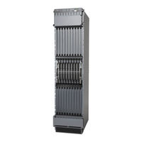
Juniper MX2020 Hardware Manual (800 pages)
Universal Routing Platform
Brand:
Juniper
| Category:
Network Router
| Size: 45.57 MB
Table of Contents
Table of Contents
3
About the Documentation
20
Documentation and Release Notes
20
Using the Examples in this Manual
20
Merging a Full Example
21
Merging a Snippet
22
Documentation Conventions
22
Documentation Feedback
25
Requesting Technical Support
25
Creating a Service Request with JTAC
26
Self-Help Online Tools and Resources
26
1 Overview
27
MX2020 System Overview and Architecture
29
MX2020 Universal Edge Router Overview
29
MX Series Router Architecture
30
MX2020 Chassis Description
32
MX2020 Backplane Description
38
MX2020 Component Redundancy
39
MX2020 Field-Replaceable Units
45
MX Series Router Packet Forwarding Engine (PFE) Architecture
47
Line Cards Supported on MX Series Routers
48
Dpcs
49
Fpcs and Pics
49
Mpcs and Mics
50
Switch Fabric Boards (SFB, SFB2, SFB3)
50
Mx2000 Adc
51
Routing Engines and CB-Res
51
Switch Control Boards
51
Ethernet Frame Counts and Statistics on MX Series Routers
52
MX2020 Router Hardware Components and CLI Terminology
52
Understanding Trio Layer 2 Feature Parity
56
Alarm and Display Components
57
MX2020 Craft Interface Description
57
MX2020 Alarm Relay Contacts on the Craft Interface
59
MX2020 Alarm Leds and Alarm Cutoff/Lamp Test Button
60
Cable and Rack Management
62
MX2020 Cable Management Description
62
Standard Cable Management System
62
Extended Cable Management System
65
MX2020 Rack-Mounting Hardware
67
Cooling System Components and Descriptions
69
MX2020 Cooling System Description
69
MX2020 Fan Tray LED
72
Host Subsystem Components
73
MX2000 Host Subsystem CB-RE Description
73
RE-MX2000-1800X4 CB-RE Description
74
RE-MX2000-1800X4 CB-RE Front Panel
75
RE-MX2000-1800X4 CB-RE Components
76
MX2000 Host Subsystem CB-RE Description | 49
77
RE-MX2000-1800X4 CB-RE Boot Sequence
77
RE-MX2000-1800X4 CB-RE Software
77
REMX2K-X8-64G and REMX2K-X8-64G-LT CB-RE Description
78
REMX2K-X8-64G CB-RE Components
78
REMX2K-X8-64G and REMX2K-X8-64G-LT CB-RE Boot Sequence
80
CB-RE Leds
80
REMX2K-X8-128G CB-RE Description
84
REMX2K-X8-128G CB-RE Components
84
REMX2K-X8-128G CB-RE Leds
86
REMX2K-X8-128G CB-RE Boot Sequence
87
MX2000 Switch Fabric Board (SFB) Overview
87
Interface Modules- Adcs, Mpcs, and Mics
88
MX2000 Modular Interface Card (MIC) Description
88
Mics Supported by MX Series Routers
89
MX2020 Modular Interface Card Leds
99
MX2020 Modular Port Concentrator (MPC) Description
99
MPC Components
101
Mpcs Supported by MX Series Routers
102
MX2020 Modular Port Concentrator Leds
106
MX2000 Adapter Card (ADC) Description
107
MPC Terminology
108
MX2020 Port and Interface Numbering
110
Power Subsystem
114
MX2020 Power Subsystem Description
114
MX2020 Power Midplane Description
119
MX2000 Three-Phase Delta AC Power Distribution Module Description
119
MX2000 Three-Phase Wye AC Power Distribution Module Description
121
MX2000 Seven-Feed Single-Phase AC Power Distribution Module Description
124
MX2000 Nine-Feed Single-Phase AC Power Distribution Module Description
125
MX2000 Three-Phase Delta and Wye AC Power Distribution Module Leds
126
MX2000 AC Power Supply Module Description
126
MX2020 AC Power Supply Module Leds
129
MX2020 DC Power Distribution Module (-48 V) Description
130
MX2000 DC Power Distribution Module (240 V China) Description
132
MX2020 DC Power Distribution Module (-48 V) Leds
133
MX2000 DC Power Distribution Module (240 V China) Leds
134
MX2020DC Power Supply Module (-48 V) Description
135
MX2000 DC Power Supply Module (240 V China) Description
138
MX2020 DC and Power Supply Module Leds
140
2 Site Planning, Preparation, and Specifications
142
Planning and Preparing the Site
144
Overview of Preparing the Site for the MX2020 Router
144
MX2020 Site Preparation Checklist
146
MX2020 Physical Specifications
148
MX2020 Rack Requirements
153
Rack Size and Strength
153
Connection to the Building Structure
155
Spacing of Mounting Bracket Holes
155
MX2020 Cabinet Size and Clearance Requirements
156
Clearance Requirements for Airflow and Hardware Maintenance for the MX2020 Router
156
MX2020 Cabinet Airflow Requirements
159
MX2020 Router Environmental Specifications
160
MX2000 Router Grounding Specifications
161
MX2000 Series Chassis Grounding Points Specifications
162
MX2000 Series Router Grounding Cable Lug Specifications
162
MX2000 Series Router Grounding Cable Specifications
163
MX2020 Chassis Moving Guidelines
164
MX2020 Moving Requirements and Guidelines Using a Router Transport Kit
165
Router Transport Kit Turning Radius
165
Router Transport Kit Requirements
166
Rack-Mounting Requirements
169
Transceiver and Cable Specifications
172
Calculating Power Budget and Power Margin for Fiber-Optic Cables
172
Calculating Power Budget for Fiber-Optic Cable
172
Calculating Power Margin for Fiber-Optic Cable
173
Signal Loss in Multimode and Single-Mode Fiber-Optic Cable
174
Understanding Fiber-Optic Cable Signal Loss, Attenuation, and Dispersion
174
Attenuation and Dispersion in Fiber-Optic Cable
175
CB-RE and RCB Interface Cable and Wire Specifications for MX Series Routers
176
Pinout Specifications
177
RJ-45 Connector Pinouts for MX Series CB-RE Auxiliary and Console Ports
177
Connector Pinouts for an MX Series CB-RE or RCB Management Port
178
Management Cable Specifications
179
Console Port Connector Pinout Information
179
RJ-45 to DB-9 Serial Port Adapter Pinout Information
180
Mini-USB Port Pinout Specifications
181
RJ-45 Management Port Connector Pinout Information
182
Port, QSFP+ Port, QSFP28 Port, SFP+ Port, and SFP Port Connector Pinout Information
182
AC Power Requirements, Specifications, and Guidelines
189
MX2020 AC Power Requirements
189
MX2000 AC Power Cord Specifications
198
MX2000 AC Power System Electrical Specifications
201
AC Power Supply Input Fuses
202
MX2000 Router Grounding Specifications
203
MX2000 Series Chassis Grounding Points Specifications
204
MX2000 Series Router Grounding Cable Lug Specifications
204
MX2000 Series Router Grounding Cable Specifications
205
MX2000 Three-Phase Delta AC Power Distribution Module Electrical Specifications
206
MX2000 Three-Phase Wye AC Power Distribution Module Electrical Specifications
207
MX2000 Single-Phase AC Power Distribution Module Electrical Specifications
208
Calculating AC Power Requirements for MX2020 Routers
208
Mapping Input Power from AC Power Distribution Modules to AC Power Supply Modules on MX2000 Routers
212
DC Power Requirements, Specifications, and Guidelines
215
MX2020 DC Power Requirements
215
MX2020 DC Power Distribution Description
223
MX2020 DC Power Distribution (240 V China) Description
225
MX2000 Router DC Power Subsystem Electrical Specifications
227
DC Power Supply Input Fuses
228
MX2000 Router DC (240 V China) Power Subsystem Electrical Specifications
229
DC Power Supply Input Fuses
230
Determining DC Power Requirements for Your MX2020 Router
231
MX 2020 DC Power Subsystem Components
231
Understanding Power Zones in the MX2020 DC Power Subsystem
231
Calculating the DC Power Requirements for Your MX2020 Router
235
DC Power (-48 V) Circuit Breaker Requirements for the MX2020 Router
237
DC Power (240 V China) Circuit Breaker Requirements for the MX2000 Router
238
DC Power Cable Specifications for the MX2020 Router
238
3 Initial Installation and Configuration
241
Installation Overview
243
Installing an MX2020 Router Overview
243
Tools and Parts Required to Unpack the MX2020 Router
245
Tools Required to Install the MX2020 Router Using a Pallet Jack
245
Tools Required to Install the MX2020 Router Using a Router Transport Kit
246
Tools and Parts Required for Connecting an MX2000 Router to Power
246
Tools and Parts Required to Maintain the MX2020 Hardware Components
247
Tools and Parts Required for MX2020 Router Connections
248
Unpacking the Router
249
Overview of Unpacking the MX2020 Router
249
Unpacking the MX2020 Router
250
Verifying the MX2020 Parts Received
254
Unpacking the Router Transport Kit
257
Installing the Mounting Hardware
260
Installing the MX2020 Mounting Hardware for a Four-Post Rack or Cabinet
260
Installing Cage Nuts, if Needed
260
Installing the Four-Post Mounting Shelf
262
Installing the Router
265
Removing Components from the MX2020 Router Chassis before Installing It in a Rack
265
Removing the Power Distribution Modules before Installing an MX2020 Router
266
Removing the Power Supply Modules before Installing an MX2020 Router
268
Removing the Fan Trays before Installing an MX2020 Router
271
Removing the Sfbs before Installing an MX2020 Router
273
Removing the Mpcs with Adapter Card before Installing an MX2020 Router
274
Removing the Mpcs Without an Adapter Card before Installing an MX2020 Router
275
Removing the CB-Res before Installing the MX2020 Router
276
Installing a MX2020 Router Using a Pallet Jack Overview
278
Installing the Pallet Jack Attachment
279
Installing the MX2020 Router Using a Pallet Jack with Attachment
280
Installing a MX2020 Router Using a Router Transport Kit Overview
285
Installing the Router Transport Kit on the MX2020 Router
285
Securing the MX2020 Router to the Router Transport Platform
288
Installing the MX2020 Router Using a Router Transport Kit
290
Reinstalling Components in the MX2020 Router after Installing in a Rack
297
Reinstalling the Power Distribution Modules after Installing the MX2020 Router in a Rack
298
Reinstalling the Power Supply Modules after Installing the MX2020 Router
301
Reinstalling the Fan Trays after Installing the MX2020 in a Rack
303
Reinstalling the Sfbs after Installing the MX2020 Router in a Rack
305
Reinstalling the Adapter Card after Installing the MX2020 Router in a Rack
306
Reinstalling Mpcs after Installing the MX2020 Router in a Rack
307
Reinstalling the CB-Res after Installing the MX2020 Router in a Rack
308
Connecting the MX2020 to Ground
311
Grounding an MX2000 Router
311
Providing Power to the MX2020
313
Connecting Power to an MX2000 Single-Phase AC Power Distribution Module
313
Connecting AC Power to an MX2000 Router with Three-Phase Delta AC Power Distribution Modules
315
Connecting AC Power to an MX2000 Router with Three-Phase Wye AC Power Distribution Modules
320
Mapping Input Power from AC Power Distribution Modules to AC Power Supply Modules on MX2000 Routers
324
Installing MX2020 AC Power Supply Modules
327
Installing MX2000 Router DC Power Supply Modules (-48 V)
329
Installing MX2000 Router DC Power Supply Modules (240 V China)
333
Connecting Power to a DC-Powered MX2020 Router with Power Distribution Modules
337
Connecting Power to a DC-Powered MX2000 Router with DC Power Distribution Modules
341
China)
341
Connecting an MX2000 DC Router Power Distribution Module (-48 V) Cable
342
Connecting an MX2000 DC Router Power Distribution Module (240 V China) Cable
345
Powering on the DC-Powered (-48 V) MX2020 Router
347
Powering on the DC-Powered (240 V China) MX2000 Router
349
Powering on a Three-Phase AC-Powered MX2000 Router
351
Connecting the MX2020 to the Network
353
Connecting the MX2020 Router to Management and Alarm Devices
353
Connecting the MX2020 Router to a Network for Out-Of-Band Management
357
Connecting the MX2020 Router to a Console or Auxiliary Device
358
Connecting an MX2020 Router to an External Alarm-Reporting Device
360
Connecting the MX2020 Router to a Network for Out-Of-Band Management | 333
360
Connecting the MX2020 Router to a Console or Auxiliary Device | 334
361
Connecting the Alarm Relay Wires to the MX2020 Craft Interface
362
Disconnecting the Alarm Relay Wires from the MX2020 Craft Interface
363
Connecting MPC or MIC Cables to the MX2020 Router
364
Configuring the Junos os Software
367
Initially Configuring the MX2020 Router
367
Juniper MX2020 Hardware Manual (454 pages)
3D Universal Edge Router
Brand:
Juniper
| Category:
Network Router
| Size: 26.58 MB
Table of Contents
Table of Contents
3
Hardware Guide
1
List of Tables
19
Part 4 Appendixes
20
About the Documentation
23
Junos os Documentation and Release Notes
23
Documentation Conventions
23
Table 1: Notice Icons
23
Table 2: Text and Syntax Conventions
24
Documentation Feedback
25
Requesting Technical Support
25
Self-Help Online Tools and Resources
25
About the Documentation
25
Opening a Case with JTAC
26
Chapter 1 MX2020 Router Description
27
Chapter 2 MX2020 Hardware Components
27
MX2020 Router Description
29
MX2020 Router Overview
29
MX2020 Router Hardware and CLI Terminology Mapping
30
Chassis
30
Table 3: MX2020 Hardware and CLI Terminology Mapping
30
MX2020 Router Description
31
MX2020 Component Redundancy
32
Figure 1: Power Distribution from each Power Subsystem to the Frus
32
Figure 2: DC Power Subsystem Feed Redundancy
33
Figure 3: Power Distribution from Three-Phase Feed Delta PDM to the AC
33
Psms
33
Figure 4: Power Distribution from Three-Phase Feed Wye PDM to the AC
34
Psms
34
Table 4: AC PDM Delta and Wye Current Requirements
34
MX2020 Hardware Components
37
MX2020 Chassis Description
38
Figure 5: Front View of a Fully Configured MX2020 Router Chassis
39
MX2020 Hardware Components
39
Table 5: Front Components in a Fully Configured MX2020 Router
39
Figure 6: Rear View of a Fully Configured AC-Powered MX2020 Router
40
Table 6: Rear Components in a Fully Configured AC-Powered MX2020
40
Figure 7: Rear View of a Fully Configured DC-Powered MX2020 Router
42
Table 7: Rear Components in a Fully Configured DC-Powered MX2020
42
Figure 8: MX2020 Router ESD Points
44
MX2020 Rack-Mounting Hardware
45
MX2020 Backplane Description
45
MX2020 Power Midplane Description
46
MX2020 Adapter Card (ADC) Description
46
MX2020 Modular Port Concentrator Overview
47
MX2020 Modular Port Concentrator Description
47
Figure 9: Typical ADC Supported on the MX2020 Router
47
Figure 10: Typical MPC Supported on the MX2020 Router
48
MPC Components
49
Figure 11: MPC Installed in the MX2020 Router
49
MX2020 Modular Port Concentrator Leds
50
MX2020 Modular Interface Card Overview
50
MX2020 Modular Interface Card Description
50
MX2020 Modular Interface Card (MIC) Leds
50
MX2020 Host Subsystem Overview
51
MX2020 Host Subsystem Description
51
Supported CB-RE
51
CB-RE Function
51
CB-RE Slots
52
CB-RE Interface Ports
52
RE-MX2000-1800X4 CB-RE Description
53
RE-MX2000-1800X4 CB-RE Components
53
RE-MX2000-1800X4 CB-RE Boot Sequence
54
MX2020 CB-RE Description
54
Figure 12: RE-MX2000-1800X4 CB-RE Front View
54
Table 8: Components on the RE-MX2000-1800X4
54
MX2020 CB-RE Leds
56
Table 9: CB-RE Leds
56
MX2020 Switch Fabric Board Overview
57
MX2020 Switch Fabric Board Description
57
Figure 13: SFB
57
SFB Slots
58
SFB Redundancy
58
SFB Components
58
MX2020 Switch Fabric Board LED
58
MX2020 Craft Interface Overview
59
MX2020 Craft Interface Description
59
Table 10: Switch Fabric Board LED
59
Figure 14: Front Panel of the Craft Interface
60
Table 11: Craft Interface Leds, Buttons, and Connectors
60
MX2020 Alarm Leds and Alarm Cutoff/Lamp Test Button
61
MX2020 Component Leds on the Craft Interface
62
MX2020 Host Subsystem Leds and Buttons on the Craft Interface
62
Table 12: Alarm Leds and Alarm Cutoff/Lamp Test Button
62
Table 13: Host Subsystem Leds on the Craft Interface
62
MX2020 Power Supply Module Leds on the Craft Interface
63
MX2020 Line Card Leds and Buttons on the Craft Interface
63
Table 14: Power Supply Module Leds on the Craft Interface
63
Table 15: Line Card Leds on the Craft Interface
63
MX2020 SFB LED and Buttons on the Craft Interface
64
MX2020 Fan Leds on the Craft Interface
64
MX2020 Alarm Relay Contacts on the Craft Interface
64
Table 16: SFB LED on the Craft Interface
64
Table 17: Fan Leds on the Craft Interface
64
MX2020 Power Subsystem Overview
65
MX2020 Power Subsystem Description
65
MX2020 Three-Phase Delta and Wye AC Power Distribution Module
65
Overview
65
Description
65
Figure 15: Alarm Relay Contacts
65
Table 18: Alarm Relay Contacts
65
Table 19: Supported MX2020 Power System Components
67
Figure 16: Three-Phase Delta AC Power Distribution Module
68
Figure 17: Three-Phase Delta AC Power Distribution Module Connections
69
Figure 18: Three-Phase Delta AC Power Cord
69
Description
70
Figure 19: Three-Phase Wye AC Power Distribution Module
70
Figure 20: Three-Phase Wye AC Power Distribution Module Connections
71
Figure 21: Three-Phase Wye AC Power Cord
71
Leds
72
MX2020 AC Power Supply Module Description
72
Figure 22: Three-Phase Delta AC PDM Leds
72
Table 20: Three-Phase Delta AC PDM Leds
72
Figure 23: AC Power Supply Module
73
MX2020 AC Power Supply Module Leds
74
Figure 24: Selecting Input Feed on the AC Power Supply Module
74
MX2020 DC Power Distribution Module Description
75
Table 21: MX2020 AC Power Supply Module Leds
75
MX2020 DC Power Distribution Module Leds
76
Figure 25: DC Power Distribution Module
76
MX2020 DC Power Supply Module Description
77
Figure 26: DC Power Distribution Module Leds
77
Table 22: DC Power Distribution Module Leds
77
Figure 27: DC Power Supply Module
78
MX2020 DC Power Supply Module Leds
79
Figure 28: Selecting Input Feed on the DC Power Supply Module
79
MX2020 Cooling System Overview
80
MX2020 Cooling System Description
80
Table 23: MX2020 DC Power Supply Module Leds
80
Figure 29: Removing Fan Tray
81
Figure 30: Airflow through the Chassis
82
Figure 31: Adjustable Air Baffle
83
Figure 32: Upper/Lower Fan Trays with Safety Double Latch System
83
Table 24: Upper/Lower Fan Tray with Safety Double Latch System
83
MX2020 Fan Tray LED
84
MX2020 Cable Manager Description
84
Figure 33: Lower Fan Tray Air Filter
84
Table 25: Fan Tray Leds
84
Figure 34: MX2020 Cable Managers
86
Figure 35: Upper and Lower Cable Management
87
Figure 36: Middle Card-Cage Cable Manager
88
Figure 37: Middle Card-Cage Air Filter
88
Installing the MX2020 Router Mounting Hardware
89
Installing the MX2020 Router Using a Pallet Jack
89
Preparing the Site for MX2020 Router Installation
89
Setting up the MX2020 Router
89
MX2020 3D Universal Edge Router
27
Chapter 3 MX2020 Router Installation Overview
91
Installing an MX2020 Router Overview
91
Chapter 4 Preparing the Site for MX2020 Router Installation
93
MX2020 Site Preparation Checklist
93
Table 26: MX2020 Site Preparation Checklist
93
MX2020 Rack Requirements
95
Rack Size and Strength
95
Spacing of Mounting Bracket Holes
96
Connection to the Building Structure
96
Figure 38: Typical Four-Post Rack
96
Clearance Requirements for Airflow and Hardware Maintenance for the MX2020
96
Router
97
Figure 39: Chassis Dimensions and Clearance Requirements for the MX2020
97
Preparing the Site for MX2020 Router Installation
97
MX2020 Cabinet Requirements
98
MX2020 Cabinet Size and Clearance Requirements
98
MX2020 Cabinet Airflow Requirements
98
Figure 40: Airflow through Chassis
99
Chapter 5 Unpacking the MX2020 Router
101
Overview of Unpacking the MX2020 Router
101
Tools and Parts Required to Unpack the MX2020 Router
101
Unpacking the MX2020 Router
102
Figure 41: MX2020 Shipping Crate Dimensions
102
Figure 42: MX2020 Shipping Crate Door
103
Verifying the MX2020 Parts Received
104
Table 27: Parts List for a Fully Configured MX2020 Router
104
Table 28: Accessory Box Parts List
105
Chapter 6 Installing the MX2020 Router Mounting Hardware
107
Installing the MX2020 Mounting Hardware for a Four-Post Rack or Cabinet
107
Installing Cage Nuts, if Needed
107
Table 29: Mounting Hole Locations for Installing the Four-Post Mounting
107
Shelf
107
Table 30: Mounting Hole Locations for Installing a MX2020 Chassis in a Four-Post
108
Installing the Four-Post Mounting Shelf
109
Figure 43: Installing the Mounting Hardware for a Four-Post Rack or Cabinet
109
Installing the MX2020 Router Mounting Hardware
109
Installing the Mx2020 Router Using a Pallet Jack
111
Chapter 7 Installing the MX2020 Router Using a Pallet Jack
111
Overview of Installing a MX2020 Router Using a Pallet Jack
111
Tools Required to Install the MX2020 Router Using a Pallet Jack
112
With a Pallet Jack
112
Removing Components from the MX2020 Router Chassis before Installing It with a Pallet Jack
112
Installing the MX2020 Router Using a Pallet Jack with Attachment
112
Removing the Power Distribution Modules before Installing an MX2020 Router with a Pallet Jack
113
Jack
113
With a Pallet Jack
113
With a Pallet Jack
114
Figure 44: Removing an AC Power Distribution Module before Installing the
114
Figure 45: Removing a DC Power Distribution Module before Installing the
114
Figure 46: Removing a AC Power Supply Module before Installing the MX2020
115
Removing the Mpcs Without an Adapter Card before Installing an MX2020 Router with a Pallet Jack
120
Jack
120
Figure 51: Removing an MPC Without the ADC
121
Chapter 8 Router
115
Figure 47: Removing a DC Power Supply Module before Installing the MX2020
116
Router
116
Figure 48: Removing Upper Fan Trays
117
Figure 49: Removing Lower Fan Trays
117
Jack
118
With a Pallet Jack
119
Figure 50: Removing an SFB
119
Installing the MX2020 Router Using a Pallet Jack with Attachment
122
Figure 52: Removing a CB-RE
122
Reinstalling Components in the MX2020 Chassis after Installing It with a Pallet
122
Figure 53: Installing the MX2020 Router into a Four-Post Rack
124
Reinstalling Components in the MX2020 Chassis after Installing It with a Pallet
124
Advertisement
Juniper MX2020 Quick Start Manual (72 pages)
3D Universal Edge Router
Brand:
Juniper
| Category:
Network Router
| Size: 5.29 MB
Table of Contents
Quick Start
1
Table of Contents
1
MX2020 Quick Start Description
3
Step 1: Prepare the Site for Installation
4
Rack-Mounting Requirements
4
Moving Requirements and Guidelines Using a Router Transport Kit
6
Tools Required to Unpack and Prepare the MX2020 Router for Installation
9
Step 2: Install the Mounting Hardware
11
Step 3: Install the Router
13
Unpack the Router
13
Remove Components
17
Unpack the Router
17
Install the Router Using a Pallet Jack with Attachment
22
Install the Pallet Jack Attachment
23
Use a Pallet Jack with Attachment to Install the Router in the Rack
24
Install the Router Using a Pallet Jack with Attachment
24
Install the Router Using a Router Transport Kit
28
Unpack the Router Transport Kit
28
Install the Router Transport Kit Onto the Router
30
Use the Transport Kit to Install the Router in the Rack
32
Step 4: Connect the Grounding Cable
43
Step 5: Reinstall Components
44
Step 6: Connect External Devices and Line Card Cables
45
Connect to a Network for Out-Of-Band Management
45
Connect a Management Console
45
Connect the Line Card Cables
45
Step 7: Connect Power Cables
47
Connect Power to a Three-Phase Delta AC Power Distribution Module
47
Connect Power to a Three-Phase Wye AC Power Distribution Module
51
Connect AC Power Supply Modules
55
See Table
56
Connect Power to a DC Power Distribution Module
58
Connect DC Power Supply Modules
60
Step 8: Perform Initial Software Configuration
64
Enter Configuration Mode
64
Configure User Accounts and Passwords
64
Configure System Attributes
65
Commit the Configuration
66
Safety Warnings
67
Compliance Statements for EMC Requirements
69
Canada
69
European Community
69
Israel
70
Japan
70
United States
70
Compliance Statements for NEBS
69
Junos os Documentation and Release Notes
71
Requesting Technical Support
71
Self-Help Online Tools and Resources
71
Opening a Case with JTAC
72
Revision History
72
Advertisement
Related Products
Juniper MX240
Juniper MX240 3D
Juniper MX204
Juniper MX2010
Juniper MX2008
Juniper MX5
Juniper MX10
Juniper MX80
Juniper MX10008
Juniper Networks MX150
Juniper Categories
Network Router
Switch
Gateway
Software
Network Hardware
More Juniper Manuals
Login
Sign In
OR
Sign in with Facebook
Sign in with Google
Upload manual
Upload from disk
Upload from URL