Table of Contents
Advertisement
Quick Links
Advertisement
Table of Contents

Related Manuals for Juniper MX2010


Summary of Contents for Juniper MX2010
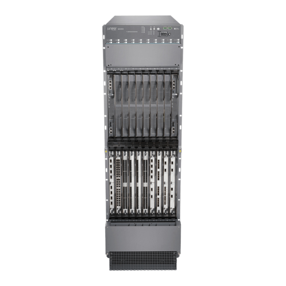
- Page 1 MX2010 Universal Routing Platform Published RELEASE 2023-10-05...
-
Page 2: Table Of Contents
Table of Contents MX2010 Quick Start Description Step 1: Prepare the Site for Installation Rack-Mounting Requirements | 2 Moving Requirements and Guidelines Using a Router Transport Kit | 5 Tools Required to Unpack and Prepare the Router for Installation | 8... - Page 3 Connect a Management Console | 58 Connect the Line Card Cables | 58 Step 7: Connect Power Cables Connect Power to a Three-Phase Delta AC Power Distribution Module | 60 Connect Power to a Three-Phase Wye AC Power Distribution Module | 64 Connect AC Power Supply Modules | 68 Connect Power to a DC Power Distribution Module | 71 Connect DC Power Supply Modules | 74...
-
Page 4: Mx2010 Quick Start Description
The MX2010 Universal Routing Platform is shipped in a wooden crate. A wooden pallet forms the base of the crate. The MX2010 chassis is bolted to this pallet. The shipping crate also contains a large rack mount tray, electromagnetic interference (EMI) cover, a cardboard accessory box, and a Quick Start (this document). -
Page 5: Step 1: Prepare The Site For Installation
Adapter cards provide housing to MPCs. The MPCs attach to the adapter cards, which in turn connect to the backplane. Up to two MICs can be installed in each MPC. Fully populated, the MX2010 router supports up to 20 MICs. - Page 6 • For the cooling system to function properly, the airflow around the chassis must be unrestricted. Allow at least 36 in. (91.44 cm) of clearance between front-to-rear-cooled routers. Allow 2.8 in. (7 cm) between the side of the chassis and any non-heat-producing surface such as a wall. NOTE: To help redirect exhaust air away from the chassis, there is an optional adjustable air baffle that can be installed on the upper fan tray access.
- Page 7 Figure 1: MX2010 Rack Clearance and Router Dimensions for Four-Post Rack...
-
Page 8: Moving Requirements And Guidelines Using A Router Transport Kit
Figure 2: MX2010 Rack Clearance and Router Dimensions for Open-Frame Rack Moving Requirements and Guidelines Using a Router Transport Kit The router requires a minimum 42 in. (106.7 cm) diameter of space to turn the chassis on the router transport kit (see... - Page 9 NOTE: The router transport kit handles can be removed to accommodate aisle width. Figure 3: Turning Diameter of Router Transport Kit The weight of the router transport kit is 138.5 lb (63 kg). The maximum recommended height the router should be lifted from the floor using the router transport kit is 1.5 in. (3.8 cm). Viewed from the side, the router with the router transport kit installed measures 59.50 in.
- Page 10 Figure 4: Measurements of the Router Transport Kit Installed on the MX2010 (Side View) Viewed from the front, the router with the router transport kit installed measures 30.78 in. (78.2 cm) wide (see Figure 5 on page...
-
Page 11: Tools Required To Unpack And Prepare The Router For Installation
Tools Required to Unpack and Prepare the Router for Installation To unpack the router and prepare for installation, you may need the following tools and equipment: NOTE: We recommend that you install the MX2010 by using a pallet jack with attachment or a router transport kit. -
Page 12: Step 2: Install The Mounting Hardware
1. Slide the large shelf between the rack rails, resting the bottom of the shelf on the rack supports. The large shelf installs on the rear rack rails, extending toward the front of the rack, as specified in the MX2010 Universal Routing Platform Hardware Guide, for large shelf installation. - Page 13 NOTE: There must be a minimum of 34-U unobstructed front-to-back usable rack space when installing the MX2010 router into a four-post rack or cabinet. 2. Partially insert screws into the open holes in the rear flanges of the four-post mounting shelf (see Figure 6 on page 11).
- Page 14 (60.96 cm) through 30 in. (76.2 cm) to accommodate different types of racks rails. NOTE: If you are installing the MX2010 router into a network cabinet, make sure that no hardware, device, rack, or cabinet component obstructs the 34-U rack space from access during...
-
Page 15: Step 3: Install The Router
Step 3: Install the Router IN THIS SECTION Unpack the Router | 12 Remove Components | 15 Install the Router Using a Pallet Jack with Attachment | 22 Install the Router Using a Router Transport Kit | 29 • "Unpack the Router" on page 12 •... - Page 16 The shipping container door can be used as a ramp to guide the MX2010 router out of the crate (see Figure 7 on page 13). Figure 7: MX2010 Shipping Crate Door To unpack the router: Move the shipping crate to a staging area as close to the installation site as possible, where you have enough room to remove the components from the chassis.
- Page 17 NOTE: If you ordered a router transport kit, the shipping crate door is used as a ramp to guide the MX2010 router out of the crate. Using a two-person team, slide the remainder of the shipping crate off the pallet.
-
Page 18: Remove Components
Figure 10 on page 19). Figure 8: Components to Remove from the Front of the MX2010 Router Remove field replacement units (FRUs) from the front of the MX2010 router before you install the router. See Table 1 on page 16... - Page 19 Table 1: Components to Remove from the Front of the MX2010 Router Component No. Component Description Slots Number of FRUs Craft interface – Switch Fabric Boards 0 through 7 (SFBs) Control Board and 0 and 1 Routing Engine (CB-RE) MPCs with ADCs and...
- Page 20 Figure 9: Components to Remove from the Rear of an AC-Powered MX2010 Router Remove field replacement units (FRUs) from the rear of an AC-powered MX2010 router before you install the router. See Table 2 on page 17 for information about MX2010 router components.
- Page 21 (Continued) Table 2: Components to Remove from the Rear of an AC-Powered MX2010 Router Component No. Component Description Slots Number of FRUs AC PSM 0 through 8 PSM air filter – AC PDM—Three-Phase delta PDM0/Input0 or wye Fan tray air filter –...
- Page 22 Figure 10: Components to Remove from the Rear of a DC-Powered MX2010 Router Remove field replacement units (FRUs) from the rear of a DC-powered MX2010 router before you install the router. See Table 3 on page 19 for information about MX2010 router components.
- Page 23 (Continued) Table 3: Components to Remove from the Rear of a DC-Powered MX2010 Router Component No. Component Description Slots Number of FRUs DC PSM 0 through 8 PSM air filter – DC PDM PDM0/Input0 DC cable manager – Fan tray air filter –...
- Page 24 4. Press and hold the latch while simultaneously pulling the fan tray out approximately 1 to 3 in. Place one hand under the fan tray for support, while pulling the fan tray completely out of the router. NOTE: The double latch system is a safety mechanism, so you cannot pull the fan tray out in one motion.
-
Page 25: Install The Router Using A Pallet Jack With Attachment
Figure 12: Removing Lower Fan Trays NOTE: For complete instructions on removing router components, see the MX2010 Universal Routing Platform Hardware Guide. Install the Router Using a Pallet Jack with Attachment IN THIS SECTION Install the Pallet Jack Attachment | 22... -
Page 26: Use The Pallet Jack With Attachment To Install The Router
(see Figure 13 on page 23). Figure 13: Installing MX2010 Pallet Jack Attachment Use the Pallet Jack with Attachment to Install the Router Before installing the router, you must remove all components (see "Remove Components"... - Page 27 Reattach the front and rear shipping covers to the chassis to help move the router. The handles on the shipping covers are used to guide the chassis during installation. CAUTION: Do not lift the router by using the handles on the shipping covers. Use these handles only to help position the router.
- Page 28 Tighten all screws. These brackets help prevent the chassis from tilting. Lower the pallet jack before moving the chassis. Doing this helps distribute the weight evenly and reduces the risk of tilting or damage to the chassis. NOTE: An empty MX2010 router weighs approximately 324 lb (146.96 kg).
- Page 29 Using the pallet jack, position the router in front of the rack or cabinet, centering it in front of the rack. NOTE: If you are installing the MX2010 router into a network cabinet, make sure that no hardware, device, rack, or cabinet component obstructs the 34-U rack space from access during installation.
- Page 30 Figure 15: Loading the MX2010 Router into a Four-Post Rack...
- Page 31 Figure 16: Loading the MX2010 Router into an Open-Frame Rack...
-
Page 32: Install The Router Using A Router Transport Kit
Install the Router Using a Router Transport Kit IN THIS SECTION Unpack the Router Transport Kit | 29 Install the Router Transport Kit onto the Router | 33 Secure the Router to the Transport Platform | 35 Use the Router Transport Kit to Install the Router in a Four-Post Rack | 38 Use the Router Transport Kit to Install the Router in an Open-Frame Rack | 48 Unpack the Router Transport Kit The router transport kit is shipped in a wooden crate. - Page 33 Figure 17: Router Transport Kit Crate Dimensions NOTE: The router transport kit is maximally protected inside the shipping crate. Do not unpack it until you are ready to begin installation. To unpack the router transport kit: 1. Move the router transport kit shipping crate to an ESD-approved staging area, where you have enough room to remove the kit for assembly.
- Page 34 Figure 18: Open Router Transport Kit Shipping Crate 4. Remove the top and front of the shipping crate, and set them aside. 5. Remove the two wing nuts that secure the wooden brace to the shipping crate platform, and set them aside.
- Page 35 Figure 19: Router Transport Kit Shipping Crate Door 7. Remove the router transport kit from the shipping container. 8. Remove the vapor corrosion inhibitor (VCI) packs attached to the pallet, being careful not to break the VCI packs open. 9. Save the shipping crate cover, pallet, and packing materials in case you need to move or ship the router transport kit at a later time.
-
Page 36: Install The Router Transport Kit Onto The Router
Install the Router Transport Kit onto the Router NOTE: The router transport kit can be purchased from Juniper Networks. The router transport kit includes the following components: • Router transport platform • Router transport left and right mounting plates with adjustable wheel assembly •... - Page 37 Figure 20: Preparing the Router Transport Kit for Installation 5. Remove the four shipping brackets that secure the router to the shipping crate platform by using a 9/16-in. (14 mm) socket wrench and a number 2 Phillips screwdriver, and set the brackets aside. 6.
-
Page 38: Secure The Router To The Transport Platform
Figure 21: Installing the Router Transport Kit onto the MX2010 Router Secure the Router to the Transport Platform 1. Ensure that the rack is in its permanent location and is secured to the building. Ensure that the installation site allows adequate clearance for router transport kit turn ratios, airflow, and maintenance. - Page 39 Figure 22: Securing the Crate Door to the Shipping Crate Platform NOTE: An empty MX2010 weighs approximately 324 lb (146.96 kg). 3. Using a two-person team on either side of the chassis, turn the handles on the router transport 4–5...
- Page 40 NOTE: The router transport kit is equipped with four T-shaped levels on top of each of the four router transport mounting brackets. Make sure the bubbles within the T-shaped levels are between the lines, indicating the chassis is level. CAUTION: Do not raise the chassis above 1 in. (2.54 cm). This will ensure the router will not tilt when transporting, which can result in injury or damage to the router.
-
Page 41: Use The Router Transport Kit To Install The Router In A Four-Post Rack
Figure 23: Securing the Router Transport Platform Use the Router Transport Kit to Install the Router in a Four-Post Rack Because of the router's size and weight—up to 985 lb (446.79 kg) depending on the configuration—we recommend that you use a router transport kit to install the router. NOTE: Four people are needed to install the router into a rack. - Page 42 CAUTION: Before front-mounting the router in a rack, have a qualified technician verify that the rack is strong enough to support the router's weight and is adequately supported at the installation site. Install the winch strap plate to the rear of the router by tightening the four captive screws (see Figure 24 on page 40).
- Page 43 Figure 24: Installing Winch Strap Plate (Four-Post Rack)
- Page 44 Using a four-person team, transport the router to the rack installation location and center it in front of the mounting shelf. NOTE: A minimum of 38 in. (96.5 cm) of clearance is required to roll the chassis sideways. NOTE: A minimum of 42 in. (106.7 cm) of circular space is required to rotate the chassis. NOTE: The router transport kit handles can be removed to accommodate aisle width.
- Page 45 Figure 25: Installing Winch Mount Bracket to Rack Rails Adjust the height of the router by turning the handles clockwise until the router transport platform is aligned with the surface of the mounting shelf and slightly higher than the mounting shelf (see Figure 26 on page 43).
- Page 46 Figure 26: Aligning the MX2010 Router with Rack Mounting Shelf...
- Page 47 Unlock the four toggle latches that secure the router transport platform to the router transport mounting plate and wheel assembly. Lift the wheels up by turning the handles counterclockwise so that the weight of the router is on the router transport platform. Using a number 3 Phillips screwdriver, loosen the captive screws that secure the router transport mounting plates and wheel assembly to the chassis, and set them aside (see Figure 27 on page...
- Page 48 Figure 27: Removing Router Transport Mounting Plate and Wheel Assembly...
- Page 49 Attach the winch strap to the winch strap plate at the rear of the router (see Figure 28 on page 46). Figure 28: Attaching Winch Strap to Winch Strap Plate 10. Attach a 1-1/8 in. (28.57 mm) torque-controlled driver or socket wrench to the winch mechanism and turn clockwise to start pulling the chassis into the rack (see Figure 29 on page 47).
- Page 50 Figure 29: Pulling the MX2010 into the Rack...
-
Page 51: Use The Router Transport Kit To Install The Router In An Open-Frame Rack
You must remove the winch bracket to perform this procedure. NOTE: There must be a minimum of 45-U of usable rack space when installing the MX2010 into a 45-U rack. 11. Remove the router transport platform, and set the platform aside. - Page 52 NOTE: A minimum of 38 in. (96.5 cm) of clearance is required to roll the chassis sideways. NOTE: A minimum of 42 in. (106.7 cm) of circular space is required to rotate the chassis. NOTE: The router transport kit handles can be removed to accommodate aisle width. Adjust the height of the router by turning the handles clockwise until the router transport platform is approximately 0.75 in.
- Page 53 Figure 30: Aligning the MX2010 Router with the Rack...
- Page 54 Unlock the four toggle latches that secure the router transport platform to the router transport mounting plate and wheel assembly. Lift the wheels up by turning the handles counterclockwise so that the weight of the router is on the router transport platform. Using a number 3 Phillips screwdriver, loosen the captive screws that secure the router transport mounting plates and wheel assembly to the chassis, and set them aside (see Figure 31 on page...
- Page 55 Figure 31: Removing Router Transport Mounting Plate and Wheel Assembly...
- Page 56 Grasping the handles on the shipping covers, carefully slide the router into the rack until the center- mounting brackets contact the rack rails (see Figure 32 on page 54).
- Page 57 Figure 32: Sliding the MX2010 into the Open-Frame Rack...
-
Page 58: Step 4: Connect The Grounding Cable
NOTE: A four-person team is needed to carefully guide the router into the rack. NOTE: There must be a minimum of 45-U of usable rack space when you install the MX2010 into a 45-U rack. Remove the router transport platform, and set the platform aside. -
Page 59: Step 5: Reinstall Components
Figure 33: Grounding Points on the MX2010 Router 8. Verify that the grounding cabling is correct, that the grounding cable does not touch or block access to router components, and that it does not drape where people could trip on it. -
Page 60: Step 6: Connect External Devices And Line Card Cables
Step 6: Connect External Devices and Line Card Cables IN THIS SECTION Connect to a Network for Out-of-Band Management | 58 Connect a Management Console | 58 Connect the Line Card Cables | 58 Figure 34: Connecting External Devices and MPC Cables... -
Page 61: Connect To A Network For Out-Of-Band Management
Connect to a Network for Out-of-Band Management 1. Turn off the power to the management device. 2. Plug one end of an RJ-45 Ethernet cable into the ETHERNET port on the CB-RE. 3. Plug the other end of the cable into the network device. Connect a Management Console 1. -
Page 62: Step 7: Connect Power Cables
Connect DC Power Supply Modules | 74 Depending on your configuration, your router uses either AC or DC power distribution modules (PDMs). Perform the appropriate procedures for each PDM in your router. For more information about PDMs, see the MX2010 Universal Routing Platform Hardware Guide. -
Page 63: Connect Power To A Three-Phase Delta Ac Power Distribution Module
Connect Power to a Three-Phase Delta AC Power Distribution Module To connect an AC power cord to an AC power source for the three-phase delta AC PDM: CAUTION: Do not mix AC and DC power modules within the same router. Attach an electrostatic discharge (ESD) grounding strap to your bare wrist, and connect the strap to an approved site ESD grounding point. - Page 64 If the PDM must be removed, both input power cables must be uninstalled and removed from the PDM before the PDM can be removed from the chassis. The MX2010 chassis is not sensitive to phase rotation sequence—either clockwise or counter clockwise will operate correctly.
- Page 65 (DVM). Then turn off the AC breaker, de-energizing the PDM, and install the metal cover and engage all AC PSMs. NOTE: The color of each AC power wire might vary. NOTE: Three-phase delta AC wire assembly kits can be purchased from Juniper Networks. Table 4: Supported Three-Phase Delta AC Wire Gauge Wire Gauge...
- Page 66 NOTE: We recommend that you use the proper gauge wire in order for the cable clamps to hold the AC cables. Using smaller gauge wiring will result in the cable clamps not tightening properly. WARNING: Power connections must be performed by a licensed electrician only. 12.
-
Page 67: Connect Power To A Three-Phase Wye Ac Power Distribution Module
NOTE: The three-phase delta AC power cord mating connector is not supplied by Juniper Networks. Table 5: Three-Phase Delta AC Power Cord Mating Cable Connector Specifications Cable Manufacturer Part Number Description Three-phase delta 460C9W 60-amp, 250 volt 3-phase, 3- pole, 4-wire, North American... - Page 68 If the PDM must be removed, both input power cables must be uninstalled and removed from the PDM before the PDM can be removed from the chassis. The MX2010 chassis is not sensitive to phase rotation sequence—either clockwise or counter clockwise will operate correctly.
- Page 69 Figure 37: Connecting Power to a Three-Phase Wye AC Power Distribution Module CAUTION: Wire label configuration is for Juniper Networks supplied cable only. If you are using your own cable, make sure you use the proper connections. To connect wires to the terminal block that serves three PSMs: a.
- Page 70 AC breaker, de-energizing the PDM, and install the metal cover and engage all AC PSMs. NOTE: The color of each AC power wire might vary. NOTE: Three-phase wye AC wire assembly kits can be purchased from Juniper Networks. Table 6: Supported Three-Phase Wye AC Wire Gauge Wire Gauge...
-
Page 71: Connect Ac Power Supply Modules
32-amp, 400 volt IP44 3 pole, 5 wire with brass contacts (red) NOTE: The three-phase wye AC power cord mating connector is not supplied by Juniper Networks. WARNING: Do not touch the power connectors on the PDM. They can contain dangerous voltages. - Page 72 ESD points on the chassis. 7. Move the switch to the on (|) position. 8. Verify that the PWR OK LED is lit green steadily. See Table 8 on page 70 for information about MX2010 AC PSM LEDs.
- Page 73 NOTE: The MX2010 systems configured for three-phase wye AC input power must use only three-phase wye AC PDMs and AC PSMs. Systems configured for three-phase delta AC input power must use three-phase delta AC PDMs and AC PSMs. AC and DC PSMs or PDMs must not be mixed within a single system.
-
Page 74: Connect Power To A Dc Power Distribution Module
Figure 40: MX2010 AC Power Supply Module Front View NOTE: Each PSM slot not occupied by an AC PSM must be covered by a PSM blank panel. Connect Power to a DC Power Distribution Module Attach an electrostatic discharge (ESD) grounding strap to your bare wrist, and connect the strap to one of the ESD points on the chassis. - Page 75 Attach the positive (+) DC source power cable lug to the RTN (return) terminal. b. Attach the negative (–) DC source power cable lug to the –48V (input) terminal. Table 9: MX2010 DC Power System Input Voltage Item Specification DC input voltage Operating range: –40 through –72 VDC...
- Page 76 Figure 41: Connecting Ground and DC Power Cables CAUTION: Ensure that each power cable lug seats flush against the surface of the terminal block as you are tightening the nuts. Ensure that each nut is properly threaded onto the terminal stud. The nut should be able to spin freely with your fingers when it is first placed onto the terminal stud.
-
Page 77: Connect Dc Power Supply Modules
12. Close the cable restraint cover over the terminal studs, and tighten the captive screws. Connect DC Power Supply Modules To install an MX2010 DC PSM: 1. Verify that the power switch on the PSM is in the off (O) position (see Figure 42 on page 75). - Page 78 Tighten the two captive screws to secure the PSM to the chassis. NOTE: The MX2010 systems configured for DC input power must use only DC PDMs and DC PSMs. AC and DC PSMs or PDMs must not be mixed within a single system.
- Page 79 Table 10: MX2010 DC Power Supply Module LEDs Label Color State Description PWR OK Green PSM is functioning normally with no alarms. Yellow PSM controller is functioning normally. – PSM is not functioning normally or the PSM controller is off.
-
Page 80: Step 8: Perform Initial Software Configuration
Figure 43: MX2010 DC Power Supply Module Front View NOTE: Each PSM slot not occupied by a DC PSM must be covered by a PSM blank panel. Step 8: Perform Initial Software Configuration IN THIS SECTION Enter Configuration Mode | 78... -
Page 81: Enter Configuration Mode
Check the LEDs on the craft interface to verify the hardware status after reinstalling or powering on the MX2010 router. For a list of system status verification commands, see the MX2010 Universal Routing Platform Hardware Guide https:/ /www.juniper.net/documentation/. To configure the software: Enter Configuration Mode 1. -
Page 82: Configure System Attributes
1. Add a password to the root administration user account. Enter a clear-text password. [edit] root# set system root-authentication plain-text-password password New password: password Retype new password: 2. Create a management console user account. [edit] user-name authentication plain-text-password root# set system login user password New Password: password... - Page 83 user-name @ host-name > 2. Configure the IP address of the DNS server. [edit] address root# set system name-server 3. Configure the router’s domain name. [edit] domain-name roott# set system domain-name 4. Configure the IP address and prefix length for the router’s management Ethernet interface. [edit] address/prefix-length root # set interfaces fxp0 unit 0 family inet address...
-
Page 84: Commit The Configuration
Commit the Configuration 1. Display the configuration to verify that it is correct. [edit] root@# show system { host-name ; host-name domain-name ; domain-name address ; backup-router root-authentication { authentication-method ( password | public-key ); name-server { address ; interfaces { fxp0 { unit 0 { family inet {... -
Page 85: Safety Warnings
WARNING: See installation instructions before connecting the router. This is a summary of safety warnings. For a complete list of warnings for this router, including translations, see the MX2010 Universal Routing Platform Hardware Guide. Other services should be performed by aut at https:/ /www.juniper.net/documentation/. - Page 86 Allow at least 36 in. (91.44 cm) of clearance between front to rear-cooled routers. Allow 2.8 in. (7 cm) between the side of the chassis and any non-heat-producing surface such as a wall. • Four people are required to move the MX2010 router. • Always remove the front and rear shipping covers before removing the components.
- Page 87 Networks, Inc. in the United States and other countries. All other trademarks, service marks, registered marks, or registered service marks are the property of their respective owners. Juniper Networks assumes no responsibility for any inaccuracies in this document. Juniper Networks reserves the right to change, modify, transfer, or otherwise revise this publication without notice.
Need help?
Do you have a question about the MX2010 and is the answer not in the manual?
Questions and answers