Juniper MX2020 Hardware Manual
3d universal edge router
Hide thumbs
Also See for MX2020:
- Hardware manual (630 pages) ,
- Hardware manual (800 pages) ,
- Quick start manual (72 pages)
Table of Contents
Advertisement
Quick Links
Download this manual
See also:
Hardware Manual
Advertisement
Chapters
Table of Contents
Troubleshooting

Related Manuals for Juniper MX2020


Summary of Contents for Juniper MX2020
-
Page 1: Hardware Guide
MX2020 3D Universal Edge Router Hardware Guide Published: 2013-03-26 Copyright © 2013, Juniper Networks, Inc. - Page 2 Products made or sold by Juniper Networks or components thereof might be covered by one or more of the following patents that are owned by or licensed to Juniper Networks: U.S. Patent Nos. 5,473,599, 5,905,725, 5,909,440, 6,192,051, 6,333,650, 6,359,479, 6,406,312, 6,429,706, 6,459,579, 6,493,347, 6,538,518, 6,538,899, 6,552,918, 6,567,902, 6,578,186, and 6,590,785.
-
Page 3: Table Of Contents
MX2020 Hardware Components ........ - Page 4 MX2020 Switch Fabric Board LED ........32...
- Page 5 Verifying the MX2020 Parts Received ........
- Page 6 Connecting the MX2020 Router ........109...
- Page 7 Troubleshooting the MX2020 MPCs ........198...
- Page 8 Removing the MX2020 Air Filter ........
- Page 9 MX2020 Chassis Moving Guidelines ........327...
- Page 10 MX2020 Physical Specifications ........
- Page 11 MX2020 DC Power Distribution ........359...
- Page 12 Tools and Parts Required to Remove Components from an MX2020 Router . . . 411 Packing the MX2020 Router for Shipment ....... 411 Guidelines for Packing Router Components for Shipment .
- Page 13 MX2020 Hardware Components ........
- Page 14 Figure 42: MX2020 Shipping Crate Door ....... . . 77...
- Page 15 Figure 77: MX2020 Router with AC Power Supply Modules Installed ..128 Figure 78: MX2020 AC Power Supply Module Front View ....129 Figure 79: Connecting DC Power to the MX2020 Router .
- Page 16 Figure 119: Installing a DC Power Distribution Module ..... 267 Figure 120: Connecting DC Power to the MX2020 Router ....269 Figure 121: Removing a DC Power Supply Module from the MX2020 Router .
- Page 17 Figure 150: Placing a Component into an Electrostatic Bag ....321 Figure 151: MX2020 Declaration of Conformity ......349...
- Page 18 MX2020 3D Universal Edge Router Hardware Guide xviii Copyright © 2013, Juniper Networks, Inc.
-
Page 19: List Of Tables
MX2020 Hardware Components ........ -
Page 20: Part 4 Appendixes
Connecting the MX2020 Router ........109... - Page 21 Appendix F MX2020 Cable Connector Pinouts ....... . . 391 Table 65: RJ-45 Connector Pinout for the CB-RE MGMT Port .
- Page 22 MX2020 3D Universal Edge Router Hardware Guide xxii Copyright © 2013, Juniper Networks, Inc.
-
Page 23: About The Documentation
Junos OS Release Notes. ® To obtain the most current version of all Juniper Networks technical documentation, see the product documentation page on the Juniper Networks website at http://www.juniper.net/techpubs/ Documentation Conventions Table 1 on page xxiii defines the notice icons used in this guide. -
Page 24: Table 2: Text And Syntax Conventions
MX2020 3D Universal Edge Router Hardware Guide Table 2 on page xxiv defines the text and syntax conventions used in this guide. Table 2: Text and Syntax Conventions Convention Description Examples Bold text like this Represents text that you type. -
Page 25: Documentation Feedback
7 days a week, 365 days a year. Self-Help Online Tools and Resources For quick and easy problem resolution, Juniper Networks has designed an online self-service portal called the Customer Support Center (CSC) that provides you with the following features:... -
Page 26: Opening A Case With Jtac
Download the latest versions of software and review release notes: http://www.juniper.net/customers/csc/software/ Search technical bulletins for relevant hardware and software notifications: https://www.juniper.net/alerts/ Join and participate in the Juniper Networks Community Forum: http://www.juniper.net/company/communities/ Open a case online in the CSC Case Management tool: http://www.juniper.net/cm/... -
Page 27: Mx2020 3D Universal Edge Router
PART 1 MX2020 3D Universal Edge Router MX2020 Router Description on page 3 MX2020 Hardware Components on page 11 Copyright © 2013, Juniper Networks, Inc. - Page 28 MX2020 3D Universal Edge Router Hardware Guide Copyright © 2013, Juniper Networks, Inc.
-
Page 29: Mx2020 Router Description
The MX2020 router is 45 rack units (U) tall. One router can be installed in a four-post rack or cabinet. The MX2020 router has 20 dedicated line card slots which means a... -
Page 30: Mx2020 Router Hardware And Cli Terminology Mapping
MX2020 3D Universal Edge Router Hardware Guide MX2020 Router Hardware and CLI Terminology Mapping Table 3 on page 4 describes the hardware terms used in MX2020 router documentation and the corresponding terms used in the Junos OS command line interface (CLI). -
Page 31: Mx2020 Router Description
Chapter 1: MX2020 Router Description Table 3: MX2020 Hardware and CLI Terminology Mapping (continued) Hardware Item Value (as (as dipslayed in Description (as displayed in the Additional the CLI) displayed in the CLI) CLI) Item in Documentation Information ADC (n) -
Page 32: Mx2020 Component Redundancy
If the master host subsystem (or either of its components) fails, the backup can take over as the master. DC power subsystem—The MX2020 DC power system is made up of two subsystems. Each subsystem provides power to ten line card slots, one local fan tray and critical FRUs. -
Page 33: Figure 2: Dc Power Subsystem Feed Redundancy
“MX2020 DC Power Supply Module Description” on page AC power subsystem—The MX2020 supports connection of a three-phase AC power system. There are two types of three-phase power systems: the three-phase delta and three-phase wye. The AC power going to the PSMs is split into three individual phases—each PSM works on a single phase. -
Page 34: Figure 4: Power Distribution From Three-Phase Feed Wye Pdm To The Ac
NOTE: This is the minimum required to provide 2.5KW per PSM. Based on facilities guidelines, you should over-provision the MX2020 router. The two numbers listed in the current columns reflect the distribution of phases from the feed to PSM. For example, from one feed each phase goes to two PSMs and from other feed each phase goes to only one PSM. - Page 35 60-amp or 80-amp current limit. The capacity of these feeds is relayed to system software through a switch located on the DC PDM. The MX2020 router supports two types of three–phase power system PDMs. The three–phase delta and three–phase wye.
- Page 36 MX2020 3D Universal Edge Router Hardware Guide Copyright © 2013, Juniper Networks, Inc.
-
Page 37: Mx2020 Hardware Components
MX2020 Rack-Mounting Hardware on page 19 MX2020 Backplane Description on page 19 MX2020 Power Midplane Description on page 20 MX2020 Adapter Card (ADC) Description on page 20 MX2020 Modular Port Concentrator Overview on page 21 MX2020 Modular Interface Card Overview on page 24... -
Page 38: Mx2020 Chassis Description
There must be a minimum of 45U of usable rack space when installing the MX2020 router into a 45U rack. NOTE: If you are installing the MX2020 router into a network cabinet, make sure that no hardware, device, rack, or cabinet component obstructs the 45U rack space from access during installation. -
Page 39: Mx2020 Hardware Components
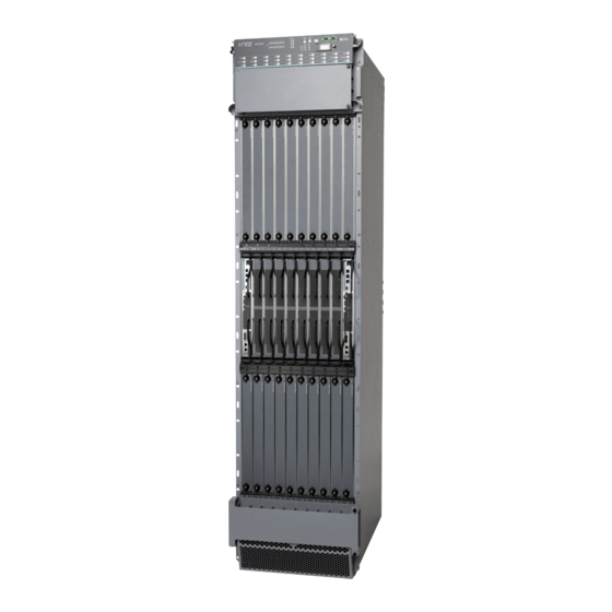
Figure 5: Front View of a Fully Configured MX2020 Router Chassis M X2 ONLI OFFL Remove field replacement units (FRUs) from the front of the MX2020 router before you install the router. See Table 5 on page 13 for information on MX2020 router components. -
Page 40: Figure 6: Rear View Of A Fully Configured Ac-Powered Mx2020 Router
Figure 6: Rear View of a Fully Configured AC-Powered MX2020 Router Chassis Remove field replacement units (FRUs) from the rear of the MX2020 router before you install the router. See Table 6 on page 14 for information on MX2020 router components. - Page 41 Chapter 2: MX2020 Hardware Components Table 6: Rear Components in a Fully Configured AC-Powered MX2020 Router (continued) Component Component Description Slots Number of FRUs AC PSM 9 through 17 PSM air filter – AC PDM—Three-phase PDM2 delta or wye AC PDM—Three-phase...
-
Page 42: Figure 7: Rear View Of A Fully Configured Dc-Powered Mx2020 Router
MX2020 3D Universal Edge Router Hardware Guide Figure 7: Rear View of a Fully Configured DC-Powered MX2020 Router Chassis Remove field replacement units (FRUs) from the rear of the MX2020 router before you install the router. See Table 7 on page 16 for information on MX2020 router components. - Page 43 Fan tray 0 and fan tray 1 (behind access door) The MX2020 router has four electrostatic discharge (ESD) points. Two are located on either side of the upper MPCs on the front of the chassis. A second pair is located on...
-
Page 44: Figure 8: Mx2020 Router Esd Points
Related MX2020 Physical Specifications on page 351 Documentation Installing the MX2020 Mounting Hardware for a Four-Post Rack or Cabinet on page 81 MX2020 Router Grounding Specifications on page 380 MX2020 Chassis Moving Guidelines on page 327 Copyright © 2013, Juniper Networks, Inc. -
Page 45: Mx2020 Rack-Mounting Hardware
Documentation MX2020 Backplane Description on page 19 Installing the MX2020 Mounting Hardware for a Four-Post Rack or Cabinet on page 81 MX2020 Backplane Description Backplanes are located toward the rear of the chassis and form the rear of the card cage. -
Page 46: Mx2020 Power Midplane Description
MPCs attach to the ADCs which in turn attach to the backplane. Future MPCs for the MX2020 can be used without an ADC. The MX2020 router has 20 dedicated line card slots, which means a maximum of 20 ADCs can be installed. The dedicated slots are numbered... -
Page 47: Mx2020 Modular Port Concentrator Overview
Removing the MPCs without an Adapter Card Before Installing an MX2020 Router with a Pallet Jack on page 94 Reinstalling the MPCs After Installing the MX2020 Router with a Pallet Jack on page 106 Reinstalling the Adapter Card After Installing the MX2020 Router with a Pallet Jack... -
Page 48: Figure 10: Typical Mpc Supported On The Mx2020 Router
Each MPC is equipped with up to four Junos Trio chipsets, which perform control functions tailored to the MPC’s media type. The MX2020 router supports up to 20 MPCs. For power requirements, see “Calculating DC Power Requirements for MX2020 Routers” on page 365 “Calculating AC Power... -
Page 49: Mpc Components
Chapter 2: MX2020 Hardware Components Figure 11: MPC Installed in the MX2020 Router MPC Components Each MPC consists of the following components: MIC card carrier, which includes two MIC slots (excludes the fixed configuration MPC). Fabric interfaces. Two Gigabit Ethernet interfaces that allow control information, route information, and statistics to be sent between the routing engine and the CPU on the MPCs. -
Page 50: Mx2020 Modular Port Concentrator Leds
Replacing an MX2020 MPC on page 242 MX2020 Modular Interface Card Overview MX2020 Modular Interface Card Description on page 24 MX2020 Modular Interface Card (MIC) LEDs on page 24 MX2020 Modular Interface Card Description The Modular Interface Cards (MICs) install into the Modular Port Concentrators (MPCs) and provide the physical connections to various network media types. -
Page 51: Mx2020 Host Subsystem Overview
Supported CB-RE The CB-RE is hot-pluggable. Some key attributes of the MX2020 CB-RE are: Control Board and Routing Engine (CB-RE) into one FRU. Air diverter to isolate upper and lower cooling zones. -
Page 52: Cb-Re Slots
ExtClk-0 ExtClk-1 —Connect the CB-RE to an external clock device through a serial cable with an RJ-45 connector. Related MX2020 CB-RE LEDs on page 30 Documentation Maintaining the MX2020 Host Subsystem on page 163 Copyright © 2013, Juniper Networks, Inc. -
Page 53: Re-Mx2000-1800X4 Cb-Re Description
Chapter 2: MX2020 Hardware Components Taking an MX2020 Host Subsystem Offline on page 230 Effect of Taking the MX2020 Host Subsystem Offline on page 228 Removing an MX2020 CB-RE on page 232 RJ-45 Connector Pinouts for MX Series CB-RE AUX and CONSOLE Ports on page 392... -
Page 54: Re-Mx2000-1800X4 Cb-Re Boot Sequence
MX2020 3D Universal Edge Router Hardware Guide Reset button—Reboots the Routing Engine on the CB-RE when pressed. Online/Offline button—Takes the Routing Engine on the CB-RE online or offline when pressed. LEDs—Provide status of the Routing Engine on the CB-RE. RE-MX2000-1800x4 CB-RE Boot Sequence The router is shipped with the Junos OS preinstalled on the CB-RE. - Page 55 RJ-45 Connector Pinouts for MX Series CB-RE AUX and CONSOLE Ports on page 392 Documentation RJ-45 Connector Pinouts for an MX Series CB-RE MANAGEMENT Port on page 391 Removing an MX2020 CB-RE on page 232 MX2020 Host Subsystem Description on page 25 Copyright © 2013, Juniper Networks, Inc.
-
Page 56: Mx2020 Cb-Re Leds
MX2020 3D Universal Edge Router Hardware Guide MX2020 CB-RE LEDs Each Routing Engine on the CB-RE (model number RE-MX2000-1800X4) has three LEDs that indicate its status. The LEDs, labeled ONLINE MASTER OK/FAIL , are located directly on the faceplate of the CB-RE. -
Page 57: Mx2020 Switch Fabric Board Overview
MX2020 Switch Fabric Board Description on page 31 MX2020 Switch Fabric Board LED on page 32 MX2020 Switch Fabric Board Description The MX2020 Switch Fabric Board (SFB) straddles the two backplanes. It has connectors connecting to both backplanes, (see Figure 13 on page 31). -
Page 58: Sfb Slots
MX2020 3D Universal Edge Router Hardware Guide SFB Slots The user can install up to eight SFBs in the MX2020 router. The SFBs install vertically into the front of the chassis in the slots labeled through . If any slots are empty, you must install a blank panel. -
Page 59: Mx2020 Craft Interface Overview
MX2020 Craft Interface Overview MX2020 Craft Interface Description on page 33 MX2020 Alarm LEDs and Alarm Cutoff/Lamp Test Button on page 35 MX2020 Component LEDs on the Craft Interface on page 36 MX2020 Alarm Relay Contacts on the Craft Interface on page 38... -
Page 60: Figure 14: Front Panel Of The Craft Interface
MX2020 3D Universal Edge Router Hardware Guide Figure 14: Front Panel of the Craft Interface MX2020 RE 0 RE 1 MASTER M/S CHASSIS NUM ONLINE OFFLINE CB-RE CB-RE Table 11: Craft Interface LEDs, Buttons, and Connectors Function No. Label Description... -
Page 61: Mx2020 Alarm Leds And Alarm Cutoff/Lamp Test Button
Replacing the MX2020 Craft Interface on page 214 Documentation MX2020 Craft Interface Serial Number Label on page 402 MX2020 Alarm LEDs and Alarm Cutoff/Lamp Test Button Two large alarm LEDs are located at the upper right of the craft interface. When lit, the circular red LED indicates a critical condition that can result in a system shutdown. -
Page 62: Mx2020 Component Leds On The Craft Interface
MX2020 Router Overview on page 3 MX2020 Component LEDs on the Craft Interface MX2020 Host Subsystem LEDs and Buttons on the Craft Interface on page 36 MX2020 Power Supply Module LEDs on the Craft Interface on page 37 MX2020 Line Card LEDs and Buttons on the Craft Interface on page 37... -
Page 63: Mx2020 Power Supply Module Leds On The Craft Interface
There are twenty push buttons located next to each of the line cards on the craft interface. These buttons are used to place the line cards online or offline. When a line card is inserted into an ADC, and installed into the MX2020 router the online/offline buttons can turn both cards on or off. -
Page 64: Mx2020 Sfb Led And Buttons On The Craft Interface
MX2020 Craft Interface Description on page 33 Documentation MX2020 Alarm Relay Contacts on the Craft Interface on page 38 MX2020 Alarm Relay Contacts on the Craft Interface The craft interface has two alarm relay contacts for connecting the router to external alarm devices. -
Page 65: Mx2020 Power Subsystem Overview
MX2020 DC Power Supply Module LEDs on page 53 MX2020 Power Subsystem Description The MX2020 router uses AC or DC power distribution modules (PDMs) and AC or DC power supply modules (PSMs). The MX2020 router is configurable with up to four AC or DC PDMs (two per subsystem), and up to eighteen AC or DC PSMs. - Page 66 MX2020 3D Universal Edge Router Hardware Guide DC power subsystem—The MX2020 DC power system is made up of two subsystems. Each subsystem provides power to ten line card slots, one local fan tray and critical FRUs. These critical FRUs consist of two CB-REs, eight SFBs located in the center of the chassis, and two fan trays (one for each zone).
-
Page 67: Table 19: Supported Mx2020 Power System Components
Table 19 on page NOTE: The MX2020 systems configured for DC input power must use only DC PDMs and DC PSMs. Systems configured for three-phase wye AC input power must use only three-phase wye AC PDMs and AC PSMs. Systems configured for three-phase delta AC input power must use only three-phase delta AC PDMs and AC PSMs. -
Page 68: Figure 16: Three-Phase Delta Ac Power Distribution Module
MX2020 Three-Phase Delta AC Power Distribution Module Description on page 42 MX2020 Three-Phase Wye AC Power Distribution Module Description on page 44 MX2020 Three-Phase Delta and Wye AC Power Distribution Module LEDs on page 46 MX2020 Three-Phase Delta AC Power Distribution Module Description Each three-phase delta AC PDM weighs approximately 8.0 lb (3.62 kg). -
Page 69: Figure 17: Three-Phase Delta Ac Power Distribution Module Connections
Related MX2020 Power Subsystem Description on page 39 Documentation Maintaining the MX2020 Power Supply Modules on page 186 Troubleshooting the MX2020 Power Subsystem on page 202 MX2020 AC Power Requirements on page 373 MX2020 AC Power Subsystem Electrical Specifications on page 369 MX2020 AC Power Cord Specifications on page 370 Copyright ©... -
Page 70: Description
If the PDM must be removed, both input power cables must be uninstalled and removed from the PDM before the PDM can be removed from the chassis. The MX2020 chassis is not sensitive to phase rotation sequence—either CW or CCW will operate correctly. -
Page 71: Figure 20: Three-Phase Wye Ac Power Distribution Module Connections
Related MX2020 Power Subsystem Description on page 39 Documentation Maintaining the MX2020 Power Supply Modules on page 186 Troubleshooting the MX2020 Power Subsystem on page 202 MX2020 AC Power Requirements on page 373 MX2020 AC Power Cord Specifications on page 370... -
Page 72: Leds
MX2020 AC Power Requirements on page 373 MX2020 AC Power Supply Module Description The MX2020 supports a three-phase AC power system. There are two types of three-phase power systems that can be installed in the router—three-phase delta or three-phase wye. The PSMs work with a single phase only. Each phase from the each of the two feeds is distributed among one or two PSMs. -
Page 73: Figure 23: Ac Power Supply Module
, and SFBs in slot through NOTE: The MX2020 systems configured for three-phase wye AC input power must use only three-phase wye AC PDMs and AC PSMs. The systems configured for three-phase delta AC input power must use three-phase delta AC PDMs and AC PSMs. -
Page 74: Mx2020 Ac Power Supply Module Leds
PWR OK FAULT INP0 INP1 Related MX2020 AC Power Supply Module LEDs on page 48 Documentation MX2020 AC Power Cord Specifications on page 370 Installing the MX2020 Air Filter on page 225 Removing the MX2020 Air Filter on page 222 MX2020 AC Power Supply Module LEDs Each AC PSM faceplate contains four LEDs. -
Page 75: Mx2020 Dc Power Distribution Module Description
PDM0 through PDM3 (bottom to top). A minimum of one PDM is required per subsystem (two PDMs per MX2020 chassis) for nonredundant power. The DC PDMs provides power interface to nine PSMs. Four PDMs provide full redundancy. NOTE: Power backplane distributes regulated 52VDC to all boards supplied by that subsystem. -
Page 76: Mx2020 Dc Power Distribution Module Leds
MX2020 Router Grounding Specifications on page 380 Calculating DC Power Requirements for MX2020 Routers on page 365 DC Power Circuit Breaker Requirements for the MX2020 Router on page 358 MX2020 DC Power Distribution on page 359 DC Power Cable Specifications for the MX2020 Router on page 360... -
Page 77: Mx2020 Dc Power Supply Module Description
MX2020 DC Power Subsystem Electrical Specifications on page 357 MX2020 DC Power Supply Module Description The MX2020 supports a two zone DC power system. Each zone (upper and lower) is provided power by one half of the power subsystem. In the DC power configuration, the... -
Page 78: Figure 27: Dc Power Supply Module
MX2020 3D Universal Edge Router Hardware Guide NOTE: The MX2020 systems configured for DC input power must use only DC PDMs and DC PSMs. AC and DC PSMs or PDMs must not be mixed within a single system. Up to nine PSMs may be connected in parallel to increase available system power across MPCs as needed and provide redundancy. -
Page 79: Mx2020 Dc Power Supply Module Leds
MX2020 DC Power Supply Module LEDs on page 53 Documentation MX2020 Router Grounding Specifications on page 380 DC Power Circuit Breaker Requirements for the MX2020 Router on page 358 MX2020 DC Power Distribution on page 359 DC Power Cable Specifications for the MX2020 Router on page 360... -
Page 80: Mx2020 Cooling System Overview
DC input is detected but voltage is out of range. – DC input to the PSM is not present. Related MX2020 Component LEDs on the Craft Interface on page 36 Documentation MX2020 Power Subsystem Description on page 39 MX2020 DC Power Supply Module Description on page 51... -
Page 81: Figure 29: Removing Fan Tray
Chapter 2: MX2020 Hardware Components The cooling system components work together to keep all router components within the acceptable temperature range. The router has four fan trays, two trays located at the top, and two trays located at the bottom of the router that install horizontally. Each fan tray contains six fans. -
Page 82: Figure 30: Airflow Through The Chassis
Card cage Lower fan trays The MX2020 router provides a two-stage front-to-back cooling system. Air is pushed into the bottom inlet and up through the lower fan tray, and exits through the opening between the backplanes in the center of the chassis. This cools the bottom MPCs, half of the SFBs and CB-REs. -
Page 83: Figure 31: Adjustable Air Baffle
Chapter 2: MX2020 Hardware Components Figure 31: Adjustable Air Baffle The CB-REs and SFBs are equipped with an air baffle to deflect the exhaust air from the bottom half of the system out and direct the air to the top half MPCs. -
Page 84: Mx2020 Fan Tray Led
Documentation Maintaining the MX2020 Fan Trays on page 152 Troubleshooting the MX2020 Cooling System on page 197 MX2020 Component LEDs on the Craft Interface on page 36 MX2020 Cable Manager Description The cable management system consists of the following components:... - Page 85 Chapter 2: MX2020 Hardware Components Upper cable manager—MX2000-CBL-TOP-S Middle cable manager and air filter—MX2000-CBL-MID-S Lower cable manager—MX2000-CBL-BTM-S DC power cable manager—MX2020-DC-CBL-MGR-S The upper cable manager, (see Figure 34 on page 60) is located just below the craft interface, which has rows for routing and securing the cables away from the front of the Modular Port Concentrators (MPCs), and Modular Interface Cards (MICs).The lower...
-
Page 86: Figure 34: Mx2020 Cable Managers
MX2020 3D Universal Edge Router Hardware Guide Figure 34: MX2020 Cable Managers Front top Front bottom Rear DC Cable manager Copyright © 2013, Juniper Networks, Inc. -
Page 87: Figure 35: Upper And Lower Cable Management
Chapter 2: MX2020 Hardware Components Figure 35: Upper and Lower Cable Management Upper card cage Lower card cage The middle card-cage cable manager, (see Figure 36 on page 62 Figure 37 on page is a combination cable tray and air filter located in the middle card cage, which has rows for routing and securing the cables away from the front of the CB-REs, and SFBs. -
Page 88: Figure 36: Middle Card-Cage Cable Manager
Figure 36: Middle Card-Cage Cable Manager Figure 37: Middle Card-Cage Air Filter Related Installing the MX2020 Upper Cable Manager on page 306 Documentation Installing the MX2020 Lower Cable Manager on page 308 Installing the MX2020 DC Cable Manager on page 310 Replacing the MX2020 Cable Managers on page 305 Copyright ©... -
Page 89: Setting Up The Mx2020 Router
Unpacking the MX2020 Router on page 75 Installing the MX2020 Router Mounting Hardware on page 81 Installing the MX2020 Router Using a Pallet Jack on page 85 Connecting the MX2020 Router on page 109 Grounding and Providing Power to the MX2020 Router on page 115 Configuring Junos OS on page 139 Copyright ©... - Page 90 MX2020 3D Universal Edge Router Hardware Guide Copyright © 2013, Juniper Networks, Inc.
-
Page 91: Mx2020 Router Installation Overview
Unpacking the MX2020 Router on page 76 Verifying the MX2020 Parts Received on page 78 Install the mounting hardware. Installing the MX2020 Mounting Hardware for a Four-Post Rack or Cabinet on page 81 NOTE: There must be a minimum of 45U of usable rack space when installing the MX2020 router into a 45U rack. - Page 92 MX2020 3D Universal Edge Router Hardware Guide Installing MX2020 AC Power Supply Modules on page 127 Connecting AC Power to a MX2020 Router with Three-Phase Delta AC Power Distribution Modules on page 117 Connecting AC Power to a MX2020 Router with Three-Phase Wye AC Power...
-
Page 93: Preparing The Site For Mx2020 Router Installation
Preparing the Site for MX2020 Router Installation MX2020 Site Preparation Checklist on page 67 MX2020 Rack Requirements on page 69 Clearance Requirements for Airflow and Hardware Maintenance for the MX2020 Router on page 71 MX2020 Cabinet Requirements on page 72 MX2020 Site Preparation Checklist... - Page 94 Plan the cable routing and “Maintaining Cables That Connect management. to MX2020 MPCs or MICs” on page 175 Related Installing an MX2020 Router Overview on page 65 Documentation Unpacking the MX2020 Router on page 76 Copyright © 2013, Juniper Networks, Inc.
-
Page 95: Mx2020 Rack Requirements
Spacing of Mounting Bracket Holes on page 70 Connection to the Building Structure on page 70 Rack Size and Strength The MX2020 router is designed for installation in a rack that complies with either the following standards: Figure 38 on page A 19-in. -
Page 96: Spacing Of Mounting Bracket Holes
For maximum stability, also secure the rack to ceiling brackets. Related Clearance Requirements for Airflow and Hardware Maintenance for the MX2020 Router Documentation on page 71 MX2020 Rack-Mounting Hardware on page 19... -
Page 97: Router
Chapter 4: Preparing the Site for MX2020 Router Installation Clearance Requirements for Airflow and Hardware Maintenance for the MX2020 Router When planning the installation site, you need to allow sufficient clearance around the rack (see Figure 39 on page 71): For the cooling system to function properly, the airflow around the chassis must be unrestricted. -
Page 98: Mx2020 Cabinet Requirements
(919.48 mm) between the inside of the front door and the inside of the rear door. NOTE: If you are installing the MX2020 router into a network cabinet, make sure that no hardware, device, rack, or cabinet component obstructs the 45U rack space from access during installation. -
Page 99: Figure 40: Airflow Through Chassis
Card cage Airflow divider Card cage Lower fan trays Related Clearance Requirements for Airflow and Hardware Maintenance for the MX2020 Router Documentation on page 71 MX2020 Cabinet Size and Clearance Requirements on page 72 MX2020 Rack Requirements on page 69 MX2020 Rack-Mounting Hardware on page 19 Copyright ©... - Page 100 MX2020 3D Universal Edge Router Hardware Guide Copyright © 2013, Juniper Networks, Inc.
-
Page 101: Unpacking The Mx2020 Router
Unpacking the MX2020 Router Overview of Unpacking the MX2020 Router on page 75 Tools and Parts Required to Unpack the MX2020 Router on page 75 Unpacking the MX2020 Router on page 76 Verifying the MX2020 Parts Received on page 78... -
Page 102: Unpacking The Mx2020 Router
MX2020 3D Universal Edge Router Hardware Guide Unpacking the MX2020 Router The router is shipped in a wooden crate. A wooden pallet forms the base of the crate. The router chassis is bolted to this pallet. Metal latches secure the top and bottom in place. -
Page 103: Figure 42: Mx2020 Shipping Crate Door
The router is maximally protected inside the shipping crate. Do not unpack it until you are ready to begin installation. The shipping container door can be used as a ramp to guide the MX2020 router out of the crate (see Figure 42 on page 77). -
Page 104: Verifying The Mx2020 Parts Received
Documentation Verifying the MX2020 Parts Received on page 78 Installing the MX2020 Router Using a Pallet Jack with Attachment on page 96 Verifying the MX2020 Parts Received A packing list is included in each shipment. Check the parts in the shipment against the items on the packing list. -
Page 105: Table 28: Accessory Box Parts List
Chapter 5: Unpacking the MX2020 Router Table 27: Parts List for a Fully Configured MX2020 Router (continued) Component Quantity MICs Up to 40 SFBs Up to 8 Combed Control Board with Routing Engines (CB-REs) 1 or 2 Power distribution modules (PDMs) - Page 106 Ethernet cable, RJ-45/RJ-45, 4-pair stranded UTP, Category 5E, 15 feet long ESD wrist strap with cable Related Tools and Parts Required to Unpack the MX2020 Router on page 75 Documentation Unpacking the MX2020 Router on page 76 MX2020 Router Overview on page 3...
-
Page 107: Installing The Mx2020 Router Mounting Hardware
CHAPTER 6 Installing the MX2020 Router Mounting Hardware Installing the MX2020 Mounting Hardware for a Four-Post Rack or Cabinet on page 81 Installing the MX2020 Mounting Hardware for a Four-Post Rack or Cabinet Installing Cage Nuts, If Needed on page 81... -
Page 108: Table 30: Mounting Hole Locations For Installing A Mx2020 Chassis In A Four-Post
Hole Distance Above U Division Mounting Shelf 0.25 in. (0.6 cm) 0.14 U Table 30: Mounting Hole Locations for Installing a MX2020 Chassis in a Four-Post Rack or Cabinet Hole Distance Above U Division 63.88 in. (162.2 cm) 36.50 U 58.63 in. -
Page 109: Installing The Four-Post Mounting Shelf
Chapter 6: Installing the MX2020 Router Mounting Hardware Installing the Four-Post Mounting Shelf To install the four-post mounting shelf (see Figure 43 on page 83): Slide the shelf between the rack rails, resting the bottom of the shelf on the rack rail supports. - Page 110 MX2020 3D Universal Edge Router Hardware Guide 24in. (60.96 cm) to 30 in (76.2 cm) NOTE: There must be a minimum of 45U of usable rack space when installing the MX2020 router into a 45U rack. Related MX2020 Rack-Mounting Hardware on page 19 Documentation Copyright ©...
-
Page 111: Installing The Mx2020 Router Using A Pallet Jack
Pallet Jack Overview of Installing a MX2020 Router Using a Pallet Jack on page 85 Tools Required to Install the MX2020 Router Using a Pallet Jack on page 86 Removing Components from the MX2020 Router Chassis Before Installing It with a... -
Page 112: Tools Required To Install The Mx2020 Router Using A Pallet Jack
Removing Components from the MX2020 Router Chassis Before Installing It with a Pallet Jack on page 86 Installing the MX2020 Router Using a Pallet Jack with Attachment on page 96 Reinstalling Components in the MX2020 Chassis After Installing It with a Pallet Jack... -
Page 113: Removing The Power Distribution Modules Before Installing An Mx2020 Router With A Pallet Jack
Removing the Fan Trays Before Installing an MX2020 Router with a Pallet Jack on page 90 Removing the SFBs Before Installing an MX2020 Router with a Pallet Jack on page 92 Removing the MPCs with Adapter Card Before Installing an MX2020 Router with a... -
Page 114: With A Pallet Jack
Figure 45: Removing a DC Power Distribution Module Before Installing the MX2020 Router Removing the Power Supply Modules Before Installing an MX2020 Router with a Pallet Jack To remove the AC or DC PSMs (see Figure 46 on page 89... -
Page 115: Figure 46: Removing A Ac Power Supply Module Before Installing The Mx2020
Chapter 7: Installing the MX2020 Router Using a Pallet Jack Loosen the two captive screws that secure the PSM to the chassis. While grasping the handle on the PSM faceplate with one hand, use your other hand to guide the PSM. -
Page 116: Figure 47: Removing A Dc Power Supply Module Before Installing The Mx2020
Figure 47: Removing a DC Power Supply Module Before Installing the MX2020 Router Removing the Fan Trays Before Installing an MX2020 Router with a Pallet Jack To remove the upper and lower fan tray (see Figure 48 on page 91... -
Page 117: Figure 48: Removing Upper Fan Trays
Chapter 7: Installing the MX2020 Router Using a Pallet Jack NOTE: The double latch system is a safety mechanism, so you cannot pull the fan tray out in one motion. CAUTION: Do not stack fan trays on one another after you remove them. -
Page 118: Jack
MX2020 3D Universal Edge Router Hardware Guide Removing the SFBs Before Installing an MX2020 Router with a Pallet Jack To remove the SFBs (see Figure 50 on page 93): Place an electrostatic bag or antistatic mat on a flat, stable surface. -
Page 119: With A Pallet Jack
Figure 50: Removing an SFB OK/FAIL Removing the MPCs with Adapter Card Before Installing an MX2020 Router with a Pallet Jack To remove an MPC with an adapter card (ADC): Have ready an antistatic mat for the MPC with an ADC. Also have ready rubber safety caps for each MPC using an optical interface on the MPC that you are removing. -
Page 120: Removing The Mpcs Without An Adapter Card Before Installing An Mx2020 Router With A Pallet Jack
Place each one individually in an electrostatic bag or on its own antistatic mat on a flat, stable surface. Removing the MPCs without an Adapter Card Before Installing an MX2020 Router with a Pallet Jack To remove an MPC without an ADC (see... -
Page 121: Figure 51: Removing An Mpc Without The Adc
Chapter 7: Installing the MX2020 Router Using a Pallet Jack Figure 51: Removing an MPC without the ADC Removing the CB-REs Before Installing the MX2020 Router with a Pallet Jack To remove a CB-RE (see Figure 52 on page 96): Have ready an antistatic mat for the CB-RE. -
Page 122: Installing The Mx2020 Router Using A Pallet Jack With Attachment
Documentation MX2020 Site Preparation Checklist on page 67 Tools Required to Install the MX2020 Router Using a Pallet Jack on page 86 Installing the MX2020 Router Using a Pallet Jack with Attachment on page 96 Reinstalling Components in the MX2020 Chassis After Installing It with a Pallet Jack... - Page 123 Chapter 7: Installing the MX2020 Router Using a Pallet Jack NOTE: The instructions below are for using a pallet jack with attachment. A standard pallet jack is approximately 48 in. (121.92 cm) deep x 27 in. (68.58 cm) wide. Ensure that the rack is in its permanent location and is secured to the building. Ensure that the installation site allows adequate clearance for both airflow and maintenance.
-
Page 124: Figure 53: Installing The Mx2020 Router Into A Four-Post Rack
Related MX2020 Site Preparation Checklist on page 67 Documentation Tools Required to Install the MX2020 Router Using a Pallet Jack on page 86 Removing Components from the MX2020 Router Chassis Before Installing It with a Pallet Jack on page 86... -
Page 125: Jack
Reinstalling the Fan Trays After Installing the MX2020 Router with a Pallet Jack on page 103 Reinstalling the SFBs After Installing the MX2020 Router with a Pallet Jack on page 104 Reinstalling the Adapter Card After Installing the MX2020 Router with a Pallet... -
Page 126: Reinstalling The Power Distribution Modules After Installing The Mx2020 Router With A Pallet Jack
MX2020 3D Universal Edge Router Hardware Guide Reinstalling the Power Distribution Modules After Installing the MX2020 Router with a Pallet Jack To reinstall the AC or DC PDMs, follow this procedure for each PDM (see Figure 54 on page 100... -
Page 127: With A Pallet Jack
For the DC-powered router, make sure the switch is set to 60 A, or 80 A to match the DC circuit input feed. Reinstalling the Power Supply Modules After Installing the MX2020 Router with a Pallet Jack To reinstall the AC or DC PSMs, follow this procedure for each PSM (see... -
Page 128: Figure 56: Reinstalling An Ac Power Supply Module
MX2020 3D Universal Edge Router Hardware Guide Figure 56: Reinstalling an AC Power Supply Module Copyright © 2013, Juniper Networks, Inc. -
Page 129: Figure 57: Reinstalling A Dc Power Supply Module
Chapter 7: Installing the MX2020 Router Using a Pallet Jack Figure 57: Reinstalling a DC Power Supply Module Reinstalling the Fan Trays After Installing the MX2020 Router with a Pallet Jack To reinstall the upper or lower fan trays, (see... -
Page 130: Figure 58: Installing Upper Fan Trays
Reinstall the remaining components into the router. Figure 58: Installing Upper Fan Trays Figure 59: Installing Lower Fan Trays Reinstalling the SFBs After Installing the MX2020 Router with a Pallet Jack To reinstall an SFB (see Figure 60 on page... -
Page 131: Pallet Jack
If one of the SFBs fails, do not remove the failed SFB until you have a replacement or blank panel to install. Figure 60: Reinstalling an SFB OK/FAIL Reinstalling the Adapter Card After Installing the MX2020 Router with a Pallet Jack To reinstall an ADC (see Figure 61 on page 106): Attach an electrostatic discharge (ESD) grounding strap to your bare wrist, and connect the strap to one of the ESD points on the chassis. -
Page 132: Jack
Grasp both ejector handles, and gently close them inward simultaneously until the ADC is fully seated. Figure 61: Reinstalling an ADC Reinstalling the MPCs After Installing the MX2020 Router with a Pallet Jack To reinstall an MPC (see Figure 62 on page... -
Page 133: Jack
Chapter 7: Installing the MX2020 Router Using a Pallet Jack Figure 62: Reinstalling an MPC Reinstalling the CB-REs After Installing the MX2020 Router with a Pallet Jack To reinstall a CB-RE (see Figure 63 on page 108): Attach an electrostatic discharge (ESD) grounding strap to your bare wrist, and connect the strap to one of the ESD points on the chassis. -
Page 134: Figure 63: Reinstalling A Cb-Re
Related MX2020 Site Preparation Checklist on page 67 Documentation Tools Required to Install the MX2020 Router Using a Pallet Jack on page 86 Removing Components from the MX2020 Router Chassis Before Installing It with a Pallet Jack on page 86 Installing the MX2020 Router Using a Pallet Jack with Attachment on page 96 Copyright ©... -
Page 135: Connecting The Mx2020 Router
Wire cutters Electrostatic discharge (ESD) grounding wrist strap Related Connecting the MX2020 Router to a Network for Out-of-Band Management on page 109 Documentation Connecting the MX2020 Router to a Console or Auxiliary Device on page 110 Connecting an MX2020 Router to an External Alarm-Reporting Device on page 111... -
Page 136: Connecting The Mx2020 Router To A Console Or Auxiliary Device
It is also used for system administrators to monitor and manage the MX2020 remotely. Connecting the MX2020 Router to a Console or Auxiliary Device To use a system console to configure and manage the Routing Engine, connect it to the appropriate CONSOLE port on the CB-RE interface. -
Page 137: Connecting An Mx2020 Router To An External Alarm-Reporting Device
Data bits—8 Stop bits—1 Flow control—none Figure 66: Console and Auxiliary Ports Figure 67: Console and Auxiliary Cable Connector Table 32: Console and Auxiliary Ports on the MX2020 CB-RE Function No. Label Description Connect a laptop, modem, or other auxiliary unit. -
Page 138: Figure 68: Alarm Relay Contacts
Documentation Connecting MPC or MIC Cables to the MX2020 Router on page 113 Connecting the MX2020 Router to a Console or Auxiliary Device on page 110 Connecting the MX2020 Router to a Network for Out-of-Band Management on page 109 CB-RE Interface Cable and Wire Specifications for MX Series Routers on page 388 CB-RE Interface Cable and Wire Specifications for MX Series Routers on page 388 Copyright ©... -
Page 139: Connecting Mpc Or Mic Cables To The Mx2020 Router
Chapter 8: Connecting the MX2020 Router Connecting MPC or MIC Cables to the MX2020 Router To connect the MPCs or MICs to the network (see Figure 69 on page 114 Figure 70 on page 114): Have ready a length of the type of cable used by the component. For cable... -
Page 140: Figure 69: Attaching A Cable To A Mpc
Figure 69: Attaching a Cable to a MPC Figure 70: Attaching a Cable to a MIC Related Connecting the MX2020 Router to Management and Alarm Devices on page 109 Documentation Tools and Parts Required for MX2020 Router Connections on page 109 Grounding the MX2020 Router on page 116 Copyright ©... -
Page 141: Grounding And Providing Power To The Mx2020 Router
Mapping Input Power from Three-Phase Delta AC Power Distribution Modules to AC Power Supply Modules on the MX2020 Router on page 120 Connecting AC Power to a MX2020 Router with Three-Phase Wye AC Power Distribution Modules on page 122 Mapping Input Power from Three-Phase Wye AC Power Distribution Modules to AC... -
Page 142: Grounding The Mx2020 Router
Connecting AC Power to a MX2020 Router with Three-Phase Delta AC Power Distribution Modules on page 117 Connecting AC Power to a MX2020 Router with Three-Phase Wye AC Power Distribution Modules on page 122 Connecting Power to a DC-Powered MX2020 Router with Power Distribution Modules... -
Page 143: Connecting Ac Power To A Mx2020 Router With Three-Phase Delta Ac Power Distribution Modules
Connecting AC Power to a MX2020 Router with Three-Phase Delta AC Power Distribution Modules on page 117 Connecting AC Power to a MX2020 Router with Three-Phase Wye AC Power Distribution Modules on page 122 Connecting Power to a DC-Powered MX2020 Router with Power Distribution Modules... - Page 144 MX2020 3D Universal Edge Router Hardware Guide Detach the ESD grounding strap from the approved site ESD grounding point, and connect the strap to one of the ESD points on the chassis. Switch the power switches on all the PSM faceplates to the off ( ) position.
-
Page 145: Figure 72: Connecting Power To A Three-Phase Delta Ac Power Distribution
The three-phase delta AC PDM terminal blocks will be flipped depending on which slot the PDM gets plugged into. NOTE: The color of each AC power wire might vary. The MX2020 chassis is not sensitive to phase rotation sequence—either CW or CCW will operate correctly. -
Page 146: Mapping Input Power From Three-Phase Delta Ac Power Distribution Modules To Ac Power Supply Modules On The Mx2020 Router
MX2020 Three-Phase Delta AC Power Distribution Module Description on page 42 Documentation MX2020 Three-Phase Delta and Wye AC Power Distribution Module LEDs on page 46 Mapping Input Power from Three-Phase Delta AC Power Distribution Modules to AC Power Supply Modules on the MX2020 Router on page 120... -
Page 147: Figure 73: Mapping Ac Three-Phase Delta Power Distribution Modules Input To Ac Power Supply Modules
Chapter 9: Grounding and Providing Power to the MX2020 Router Figure 73: Mapping AC Three-Phase Delta Power Distribution Modules Input to AC Power Supply Modules MX2020 System Rear View IN P1/3_LEFT IN P1/3_RIGHT PDM3 IN P0/2_LEFT IN P0/2_RIGHT PDM2 IN P1/1_LEFT... -
Page 148: Connecting Ac Power To A Mx2020 Router With Three-Phase Wye Ac Power Distribution Modules
Distribution Modules on page 117 MX2020 Three-Phase Delta AC Power Distribution Module Description on page 42 MX2020 Three-Phase Delta and Wye AC Power Distribution Module LEDs on page 46 Powering On the AC-Powered MX2020 Router on page 129 MX2020 AC Power Subsystem Electrical Specifications on page 369... - Page 149 Chapter 9: Grounding and Providing Power to the MX2020 Router Verify that the correct three-phase wye PDMs are installed and secured in the chassis before connecting power cables. NOTE: The power cables must be uninstalled and removed from the three-phase wye PDM before removal of the PDM from the chassis.
-
Page 150: Figure 74: Connecting Power To A Three-Phase Wye Ac Power Distribution
The three-phase wye AC PDM terminal blocks will be flipped depending on which slot the PDM gets plugged into. NOTE: The color of each AC power wire might vary. The MX2020 chassis is not sensitive to phase rotation sequence—either CW or CCW will operate correctly. -
Page 151: Mapping Input Power From Three-Phase Wye Ac Power Distribution Modules To Ac Power Supply Modules On The Mx2020 Router
MX2020 Three-Phase Wye AC Power Distribution Module Description on page 44 Documentation MX2020 Three-Phase Delta and Wye AC Power Distribution Module LEDs on page 46 Mapping Input Power from Three-Phase Wye AC Power Distribution Modules to AC Power Supply Modules on the MX2020 Router on page 125... -
Page 152: Figure 75: Mapping Ac Three-Phase Wye Power Distribution Modules Input To
MX2020 3D Universal Edge Router Hardware Guide Figure 75: Mapping AC Three-Phase Wye Power Distribution Modules Input to AC Power Supply Modules MX2020 System Rear View IN P1/3_LEFT IN P1/3_RIGHT PDM3 IN P0/2_LEFT IN P0/2_RIGHT PDM2 IN P1/1_LEFT IN P1/1_RIGHT... -
Page 153: Installing Mx2020 Ac Power Supply Modules
Related MX2020 Three-Phase Wye AC Power Distribution Module Description on page 44 Documentation Connecting AC Power to a MX2020 Router with Three-Phase Wye AC Power Distribution Modules on page 122 Powering On the AC-Powered MX2020 Router on page 129 MX2020 AC Power Subsystem Electrical Specifications on page 369... -
Page 154: Figure 76: Selecting Ac Power Subsystem Feed Redundancy
PSM is fully seated in the chassis slot. Tighten the two captive screws, (see Figure 77 on page 128). Figure 77: MX2020 Router with AC Power Supply Modules Installed Verify that the and/or LEDs on the PSM are lit green steadily, (see... -
Page 155: Powering On The Ac-Powered Mx2020 Router
Each PSM slot not occupied by a AC PSM must be covered by a PSM blank panel. Related Preventing Electrostatic Discharge Damage to an MX2020 Router on page 320 Documentation Powering On the AC-Powered MX2020 Router on page 129 Powering On the AC-Powered MX2020 Router You can use this procedure for a router with either a three-phase delta AC PDM or a three-phase wye AC PDM. - Page 156 Documentation MX2020 Three-Phase Wye AC Power Distribution Module Description on page 44 Connecting the MX2020 Router to a Console or Auxiliary Device on page 110 Connecting AC Power to a MX2020 Router with Three-Phase Delta AC Power Distribution Modules on page 117...
-
Page 157: Powering Off The Ac-Powered Mx2020 Router
Preventing Electrostatic Discharge Damage to an MX2020 Router on page 320 Replacing an MX2020 AC Power Supply Module on page 301 Replacing an MX2020 Three-Phase Delta AC Power Distribution Module on page 276 Powering Off the AC-Powered MX2020 Router NOTE: After powering off a PSM, wait at least 60 seconds before turning it back on. - Page 158 MX2020 3D Universal Edge Router Hardware Guide To connect the DC source power cables to the router: Switch off the dedicated customer site circuit breakers. Ensure that the voltage across the DC power source cable leads is 0 V and that there is no chance that the cable leads might become active during installation.
- Page 159 Chapter 9: Grounding and Providing Power to the MX2020 Router Remove the nut and washers from each of the terminal studs. (Use a 7/16-in. [11 mm] nut driver or socket wrench.) Secure each power cable lug to the terminal studs, first with the split washer, then...
-
Page 160: Installing Mx2020 Dc Power Supply Modules
Grounding points (on chassis) Related DC Power Cable Specifications for the MX2020 Router on page 360 Documentation Preventing Electrostatic Discharge Damage to an MX2020 Router on page 320 Powering On the DC-Powered MX2020 Router on page 136 Installing MX2020 DC Power Supply Modules... -
Page 161: Figure 80: Selecting Dc Power Subsystem Feed Redundancy
Chapter 9: Grounding and Providing Power to the MX2020 Router Figure 80: Selecting DC Power Subsystem Feed Redundancy PWR OK FAULT INP0 INP1 Using both hands, grasp the handle and slide the PSM straight into the chassis until the PSM is fully seated in the chassis slot. Tighten the two captive screws, (see... -
Page 162: Powering On The Dc-Powered Mx2020 Router
Each PSM slot not occupied by a DC PSM must be covered by a PSM blank panel. Related Preventing Electrostatic Discharge Damage to an MX2020 Router on page 320 Documentation Powering On the DC-Powered MX2020 Router on page 136 Powering On the DC-Powered MX2020 Router... - Page 163 Chapter 9: Grounding and Providing Power to the MX2020 Router Verify that the source power cables are connected to the appropriate terminal: the positive (+) source cable to the return terminal labeled ( ) and the negative (–) source cable to the input terminal labeled ( ), on the PDMs.
-
Page 164: Powering Off The Dc-Powered Mx2020 Router
Configuring the MX2020 Router” on page 139, and Related Connecting the MX2020 Router to Management and Alarm Devices on page 109 Documentation Preventing Electrostatic Discharge Damage to an MX2020 Router on page 320 Replacing an MX2020 DC Power Supply Module on page 269... -
Page 165: Configuring Junos Os
The MX2020 router is shipped with the Junos OS preinstalled and ready to be configured when the MX2020 router is powered on. There are three copies of the software: one on a CompactFlash card in the CB-RE, one on a SSD in the CB-RE, and one on a USB flash... -
Page 166: Figure 83: Usb Flash Drive Port On Cb-Re
MX2020 3D Universal Edge Router Hardware Guide Figure 83: USB Flash Drive Port on CB-RE Gather the following information before configuring the router: Name the router will use on the network Domain name the router will use IP address and prefix length information for the Ethernet interface... - Page 167 SSH public key string (DSA or RSA). [edit] root@# set system root-authentication plain-text-password New password: password Retype new password: password [edit] root@# set system root-authentication encrypted-password encrypted-password [edit] root@# set system root-authentication ssh-dsa public-key Copyright © 2013, Juniper Networks, Inc.
- Page 168 MX2020 3D Universal Edge Router Hardware Guide [edit] root@# set system root-authentication ssh-rsa public-key (Optional) Configure the static routes to remote subnets with access to the management port. Access to the management port is limited to the local subnet. To access the management port from a remote subnet, you need to add a static route to that subnet within the routing table.
- Page 169 Powering On the AC-Powered MX2020 Router on page 129 Documentation Powering On the DC-Powered MX2020 Router on page 136 Grounding the MX2020 Router on page 116 Routine Maintenance Procedures for the MX2020 Router on page 148 Copyright © 2013, Juniper Networks, Inc.
- Page 170 MX2020 3D Universal Edge Router Hardware Guide Copyright © 2013, Juniper Networks, Inc.
-
Page 171: Mx2020 Router Hardware Maintenance, Troubleshooting, And Replacement Procedures
PART 3 MX2020 Router Hardware Maintenance, Troubleshooting, and Replacement Procedures Maintaining MX2020 Router Hardware Components on page 147 Troubleshooting MX2020 Router Hardware Components on page 193 Replacing MX2020 Router Hardware Components on page 211 Copyright © 2013, Juniper Networks, Inc. - Page 172 MX2020 3D Universal Edge Router Hardware Guide Copyright © 2013, Juniper Networks, Inc.
-
Page 173: Maintaining Mx2020 Router Hardware Components
Maintaining MX2020 Router Hardware Components Maintaining and Verifying the Status of the MX2020 Router Components on page 147 Tools and Parts Required to Maintain the MX2020 Hardware Components on page 148 Routine Maintenance Procedures for the MX2020 Router on page 148... -
Page 174: Tools And Parts Required To Maintain The Mx2020 Hardware Components
Maintaining the MX2020 Switch Processor Mezzanine Board (SPMB) on page 181 Maintaining and Verifying the MX2020 Router Version on page 149 Maintaining and Verifying the Status of the MX2020 Craft Interface on page 149 Tools and Parts Required to Maintain the MX2020 Hardware Components... -
Page 175: Maintaining And Verifying The Mx2020 Router Version
Chapter 11: Maintaining MX2020 Router Hardware Components Related Tools and Parts Required to Maintain the MX2020 Hardware Components on page 148 Documentation Maintaining the MX2020 Air Filter on page 151 Maintaining the MX2020 Fan Trays on page 152 Maintaining and Verifying the MX2020 Router Version Purpose Verify the router model, Junos OS version, and system software installed. - Page 176 MX2020 3D Universal Edge Router Hardware Guide To display the status of the craft interface, issue the show chassis craft-interface command. user@host> show chassis craft-interface Front Panel System LEDs: Routing Engine -------------------------- Fail Master Front Panel Alarm Indicators: ----------------------------- Red LED...
-
Page 177: Maintaining The Mx2020 Cooling System Components
Chassis Role Check the status-reporting devices on the craft interface: system alarms and LEDs. Related Tools and Parts Required to Maintain the MX2020 Hardware Components on page 148 Documentation Maintaining the MX2020 Cooling System Components on page 151 Maintaining the MX2020 Fan Trays on page 152... -
Page 178: Maintaining The Mx2020 Air Baffle
MX2020 3D Universal Edge Router Hardware Guide Maintaining the MX2020 Air Baffle Purpose For optimum cooling, verify the condition of the air baffle. Redirect the exhaust air to the desired direction to dissipate air away from the router. Action On a regular basis, check the air baffle and adjust accordingly to redirect exhaust air. - Page 179 Chapter 11: Maintaining MX2020 Router Hardware Components CB 1 IntakeB-Zone1 25 degrees C / 77 degrees F CB 1 IntakeC-Zone0 39 degrees C / 102 degrees F CB 1 ExhaustA-Zone0 33 degrees C / 91 degrees F CB 1 ExhaustB-Zone1...
- Page 180 MX2020 3D Universal Edge Router Hardware Guide SFB 6 IntakeA-Zone0 32 degrees C / 89 degrees F SFB 6 IntakeB-Zone1 29 degrees C / 84 degrees F SFB 6 Exhaust-Zone0 37 degrees C / 98 degrees F SFB 6 SFB-XF2-Zone1...
- Page 181 NOTE: The fan numbers are stamped into the fan tray sheet metal next to each fan. For monitoring the temperature of specific items in the MX2020 router, the output for show chassis environment monitored command is similar to the following: user@host>...
- Page 182 MX2020 3D Universal Edge Router Hardware Guide CB 1 IntakeB-Zone1 23 degrees C / 73 degrees F CB 1 IntakeC-Zone0 26 degrees C / 78 degrees F CB 1 ExhaustA-Zone0 25 degrees C / 77 degrees F CB 1 ExhaustB-Zone1...
- Page 183 Chapter 11: Maintaining MX2020 Router Hardware Components FPC 4 XM 0 Chip 57 degrees C / 134 degrees F FPC 4 XM 1 TSen 47 degrees C / 116 degrees F FPC 4 XM 1 Chip 46 degrees C / 114 degrees F...
- Page 184 MX2020 3D Universal Edge Router Hardware Guide FPC 18 MQ 0 TSen 38 degrees C / 100 degrees F FPC 18 MQ 0 Chip 39 degrees C / 102 degrees F FPC 18 MQ 1 TSen 38 degrees C / 100 degrees F...
- Page 185 Chapter 11: Maintaining MX2020 Router Hardware Components CB 1 ExhaustA-Zone0 CB 1 ExhaustB-Zone1 CB 1 TCBC-Zone0 SPMB 0 Intake SPMB 1 Intake SFB 0 Intake-Zone0 SFB 0 Exhaust-Zone1 SFB 0 IntakeA-Zone0 SFB 0 IntakeB-Zone1 SFB 0 Exhaust-Zone0 SFB 0 SFB-XF2-Zone1...
- Page 186 MX2020 3D Universal Edge Router Hardware Guide SFB 3 IntakeA-Zone0 SFB 3 IntakeB-Zone1 SFB 3 Exhaust-Zone0 SFB 3 SFB-XF2-Zone1 SFB 3 SFB-XF1-Zone0 SFB 3 SFB-XF0-Zone0 SFB 4 Intake-Zone0 SFB 4 Exhaust-Zone1 SFB 4 IntakeA-Zone0 SFB 4 IntakeB-Zone1 SFB 4 Exhaust-Zone0...
- Page 187 Chapter 11: Maintaining MX2020 Router Hardware Components SFB 7 Intake-Zone0 SFB 7 Exhaust-Zone1 SFB 7 IntakeA-Zone0 SFB 7 IntakeB-Zone1 SFB 7 Exhaust-Zone0 SFB 7 SFB-XF2-Zone1 SFB 7 SFB-XF1-Zone0 SFB 7 SFB-XF0-Zone0 FPC 4 FPC 7 FPC 11 FPC 16 FPC 18...
-
Page 188: Maintaining The Mx2020 Cooling System Zones
MX2020 3D Universal Edge Router Hardware Guide ADC 18 ADC-XF1 ADC 18 ADC-XF0 For the fan trays, the output for the show chassis fan command is similar to the following: user@host> show chassis fan Item Status % RPM Measurement Fan Tray 0 Fan 1... -
Page 189: Maintaining The Mx2020 Host Subsystem
Num Fans Missing Num Fans Failed Fan Duty Cycle Maintaining the MX2020 Host Subsystem Maintaining the MX2020 Routing Engines on page 163 Maintaining the MX2020 Control Boards on page 166 Maintaining the MX2020 Routing Engines Purpose Each host subsystem comprises a Control Board and Routing Engine (CB-RE) functioning together. - Page 190 MX2020 3D Universal Edge Router Hardware Guide NOTE: Even though the Routing Engine is combined with a Control Board (CB-RE), separate LEDs on the craft interface show the status of the routing engines, and separate LEDs show the status of the control board.
- Page 191 Chapter 11: Maintaining MX2020 Router Hardware Components Load averages: 1 minute 5 minute 15 minute 0.00 0.00 0.00 For further description of the output from the command, see the Junos OS System Basics and Services Command Reference Copyright © 2013, Juniper Networks, Inc.
-
Page 192: Maintaining The Mx2020 Control Boards
MX2020 3D Universal Edge Router Hardware Guide Maintaining the MX2020 Control Boards Purpose For optimum router performance, verify the condition of the Control Board and Routing Engine (CB-RE). Action On a regular basis: Check the host subsystem LEDs on the craft interface. For more information about the LEDs and the display, see “MX2020 Craft Interface Description”... -
Page 193: Maintaining The Mx2020 Adapter Cards
Services Command Reference Related MX2020 Host Subsystem Description on page 25 Documentation MX2020 Component LEDs on the Craft Interface on page 36 Troubleshooting the MX2020 Host Subsystems on page 196 Maintaining the MX2020 Adapter Cards Purpose For optimum router performance, verify the condition of the ADCs. The router can have up to twenty ADCs mounted vertically in the line card cage at the front of the chassis. -
Page 194: Maintaining Mx2020 Packet Forwarding Engine Components
Documentation Installing an MX2020 MPC into an Adapter Card on page 249 Connecting MPC or MIC Cables to the MX2020 Router on page 113 Installing a Cable on an MX2020 MPC or MIC on page 259 Maintaining MX2020 Packet Forwarding Engine Components... - Page 195 Chapter 11: Maintaining MX2020 Router Hardware Components Action On a regular basis: Check the LEDs on the craft interface directly above each MPC slot. The green LED labeled lights steadily when a MPC is functioning normally. Check the OK/FAIL LED on the MPC. For more information, see MX Series 3D Universal .
- Page 196 MX2020 3D Universal Edge Router Hardware Guide Slot 8 information: State Online Temperature Total CPU DRAM 2048 MB Total RLDRAM 662 MB Total DDR DRAM 2560 MB Start time: 2012-11-26 16:20:18 PST Uptime: 18 hours, 5 minutes, 50 seconds Max Power Consumption...
- Page 197 Chapter 11: Maintaining MX2020 Router Hardware Components PIC 2 Online 4x10GE SFPP PIC 3 Online 1X100GE CFP Slot 7 Online MPCE Type 3 3D PIC 0 Online 1X100GE CFP PIC 2 Online 1x 10GE XFP PIC 3 Online 1x 10GE XFP...
-
Page 198: Maintaining Mx2020 Mics
MX2020 3D Universal Edge Router Hardware Guide Maintaining MX2020 MICs Purpose For optimum router performance, verify the condition of the Modular Interface Cards (MICs). Action On a regular basis: Check the LEDs on MIC faceplates. The meaning of the LED states differs for various MICs. -
Page 199: Maintaining The Mx2020 Ethernet Switch
Chapter 11: Maintaining MX2020 Router Hardware Components Maintaining the MX2020 Ethernet Switch Purpose For optimum router performance, verify the status of the Gigabit Ethernet ports connected to MPC devices. Action On a regular basis: Check the LEDs on MPC faceplates. The meaning of the LED states differs for various MICs. - Page 200 MX2020 3D Universal Edge Router Hardware Guide Link is down on GE port 12 connected to device: FPC13 Link is down on GE port 13 connected to device: FPC12 Link is down on GE port 14 connected to device: FPC14...
-
Page 201: Maintaining Cables That Connect To Mx2020 Mpcs Or Mics
Chapter 11: Maintaining MX2020 Router Hardware Components Maintaining Cables That Connect to MX2020 MPCs or MICs Purpose For optimum router performance, verify the condition of the cables that connect to the MPCs or MICs. Action On a regular basis: Use an upper cable manager and a lower cable manager (shown in... -
Page 202: Holding And Storing Mx Series Mpcs
MX2020 3D Universal Edge Router Hardware Guide The following guidelines apply specifically to fiber-optic cables: When you unplug a fiber-optic cable, always place a rubber safety plug over the transceiver on the faceplate and on the end of the cable. -
Page 203: Holding An Mx2020 Mpc
Related MX2020 Modular Port Concentrator Description on page 21 Documentation MX2020 Component LEDs on the Craft Interface on page 36 Holding an MX2020 MPC on page 177 Troubleshooting the MX2020 MPCs on page 198 Replacing an MX2020 MPC on page 242 Holding an MX2020 MPC When carrying an MPC, you can hold it either vertically or horizontally. -
Page 204: Figure 86: Do Not Grasp The Connector Edge
MX2020 3D Universal Edge Router Hardware Guide If the MPC is horizontal before you grasp it, place your left hand around the faceplate and your right hand along the bottom edge. To hold an MPC horizontally: Orient the MPC so that the faceplate faces you. -
Page 205: Storing An Mx2020 Mpc
Chapter 11: Maintaining MX2020 Router Hardware Components Figure 87: Do Not Rest the MPC on an Edge If you must rest the MPC temporarily on an edge while changing its orientation between vertical and horizontal, use your hand as a cushion between the edge and the surface. -
Page 206: Maintaining The Mx2020 Sfb
MX2020 3D Universal Edge Router Hardware Guide Carefully insert the MPC connector edge into the opening of the bag, and pull the bag toward you to cover the MPC. Never stack an MPC under or on top of any other component. -
Page 207: Maintaining The Mx2020 Switch Processor Mezzanine Board (Spmb)
Chapter 11: Maintaining MX2020 Router Hardware Components Maintaining the MX2020 Switch Processor Mezzanine Board (SPMB) Purpose For optimum router performance, verify the switch processor mezzanine board status. Action On a regular basis: Issue the command to display the status information The output... - Page 208 MX2020 3D Universal Edge Router Hardware Guide DC output: 271.69 W (Lower Zone, 5.25 A at 51.75 V, 12.94% of capacity) PSM 1: State: Online AC input: OK (INP0 feed expected, INP0 feed connected) Capacity: 2100 W (maximum 2100 W) DC output: 247.00 W (Lower Zone, 4.75 A at 52.00 V, 11.76% of capacity)
- Page 209 Chapter 11: Maintaining MX2020 Router Hardware Components PSM 11: State: Online AC input: OK (INP0 feed expected, INP0 feed connected) Capacity: 2100 W (maximum 2100 W) DC output: 273.00 W (Upper Zone, 5.25 A at 52.00 V, 13.00% of capacity)
- Page 210 MX2020 3D Universal Edge Router Hardware Guide NOTE: The capacity of the DC PSM is limited by the power feeds as indicated by the 60A/80A switch on the PDM. user@host> show chassis power PSM 0: State: Empty Input: Absent PSM 1:...
- Page 211 Junos OS System Basics and Services Command Reference Related MX2020 Power Subsystem Description on page 39 Documentation Preventing Electrostatic Discharge Damage to an MX2020 Router on page 320 Troubleshooting the MX2020 Power Subsystem on page 202 Copyright © 2013, Juniper Networks, Inc.
-
Page 212: Maintaining The Mx2020 Power Supply Modules
MX2020 3D Universal Edge Router Hardware Guide Maintaining the MX2020 Power Supply Modules Purpose For optimum router performance, verify the condition of the PSMs. Action On a regular basis: Check the status of the PSMs by issuing the command. show chassis environment psm The output displays the chassis AC PSM status: user@host>... - Page 213 Chapter 11: Maintaining MX2020 Router Hardware Components AC Input Feed Voltage(V) Current(A) Power(W) INP0 225.00 1.30 292.50 INP1 5.00 0.00 0.00 DC Output Voltage(V) Current(A) Power(W) Load(%) 52.00 4.25 221.00 10.52 Hours Used 7462 PSM 6 status: State Online Temperature...
- Page 214 MX2020 3D Universal Edge Router Hardware Guide State Online Temperature AC Input Feed Voltage(V) Current(A) Power(W) INP0 223.75 2.20 492.25 INP1 0.00 0.00 0.00 DC Output Voltage(V) Current(A) Power(W) Load(%) 52.00 8.25 429.00 20.43 Hours Used 6838 PSM 13 status:...
- Page 215 Chapter 11: Maintaining MX2020 Router Hardware Components INP1 51.20 11.55 591.36 DC Output Voltage(V) Current(A) Power(W) Load(%) 51.25 10.25 525.31 25.01 Hours Used 1369 PSM 5 status: State Online Temperature DC Input Feed Voltage(V) Current(A) Power(W) INP0 0.00 0.00 0.00 INP1 50.80...
- Page 216 Related MX2020 Power Subsystem Description on page 39 Documentation MX2020 Troubleshooting Resources on page 193 Troubleshooting the MX2020 Power Subsystem on page 202 MX2020 Site Preparation Checklist on page 67 Copyright © 2013, Juniper Networks, Inc.
-
Page 217: Maintaining The Mx2020 Chassis Fru Power On Sequence
For optimum router performance, verify the condition of the FRU power on sequence. Action On a regular basis: Check the status of the MX2020 chassis FRU power on sequence issuing the command. show chassis power sequence The output displays the chassis FRU power on sequence: user@host>... - Page 218 MX2020 3D Universal Edge Router Hardware Guide Copyright © 2013, Juniper Networks, Inc.
-
Page 219: Troubleshooting Mx2020 Router Hardware Components
Craft Interface LEDs on page 194 Component LEDs on page 195 Command-Line Interface To troubleshoot an MX2020 router, you use the Junos OS command-line interface (CLI), alarms, devices connected to the alarm relay contacts, and LEDs on both the components and craft interface. -
Page 220: Chassis And Interface Alarm Messages
Craft Interface LEDs The craft interface displays system status messages and allows you to troubleshoot the MX2020 router. The craft interface is located on the upper front of the router. It contains LEDs, buttons for the router. LEDs on the craft interface include the following:... -
Page 221: Component Leds
Chapter 12: Troubleshooting MX2020 Router Hardware Components Alarm LEDs—One large red circular LED and one large yellow triangular LED, located on the upper right of the craft interface, indicate two levels of alarm conditions. The circular red LED lights to indicate a critical condition that can result in a system shutdown. -
Page 222: Troubleshooting The Mx2020 Host Subsystems
Related MX2020 Craft Interface Description on page 33 Documentation Troubleshooting the MX2020 Cooling System on page 197 Troubleshooting the MX2020 MPCs on page 198 Troubleshooting the MX2020 MICs on page 201 Troubleshooting the MX2020 Power Subsystem on page 202... -
Page 223: Troubleshooting The Mx2020 Cooling System
Chapter 12: Troubleshooting MX2020 Router Hardware Components Use the CLI to check the alarms. Standalone MX2020 router—Issue the command to view the show chassis alarms alarms. Related MX2020 Host Subsystem Description on page 25 Documentation MX2020 Craft Interface Description on page 33... -
Page 224: Troubleshooting The Mx2020 Mpcs
Related MX2020 Craft Interface Description on page 33 Documentation Replacing an MX2020 Fan Tray on page 218 Maintaining the MX2020 Air Filter on page 151 Maintaining the MX2020 Fan Trays on page 152 Troubleshooting the MX2020 MPCs Problem... - Page 225 Chapter 12: Troubleshooting MX2020 Router Hardware Components The green LED above the MPC is not lit. Solution To troubleshoot an MPC: Monitor the green LED labeled above the MPC on the craft interface as soon as an MPC is seated in an operating router.
- Page 226 MX2020 3D Universal Edge Router Hardware Guide For further description of the output from the commands, see the Junos OS System Basics Configuration Guide user@host> show chassis fpc detail Slot 4 information: State Online Temperature Total CPU DRAM 2048 MB...
-
Page 227: Troubleshooting The Mx2020 Mics
Max Power Consumption 440 Watts Related MX2020 Craft Interface Description on page 33 Documentation MX2020 Modular Port Concentrator Description on page 21 Maintaining MX2020 MPCs on page 168 Replacing an MX2020 MPC on page 242 Troubleshooting the MX2020 MICs Problem A MIC LED lit red indicates a problem with the MIC. -
Page 228: Troubleshooting The Mx2020 Power Subsystem
MX2020 Modular Interface Card Description on page 24 Documentation Maintaining MX2020 MICs on page 172 Maintaining Cables That Connect to MX2020 MPCs or MICs on page 175 Replacing a MX2020 MIC on page 252 Troubleshooting the MX2020 Power Subsystem Problem... - Page 229 LED for each input feed. See “Mapping Input Power from Three-Phase Delta AC Power Distribution Modules to AC Power Supply Modules on the MX2020 Router” on page 120 “Mapping Input Power from Three-Phase Wye AC Power Distribution Modules to AC Power Supply Modules on the MX2020 Router” on page 125.
- Page 230 MX2020 3D Universal Edge Router Hardware Guide Connect the PDM to a different power source with new power cables. If the PSM LED still does not light, the PSM is the source of the problem. Replace the PWR OK PSM with a spare.
- Page 231 Chapter 12: Troubleshooting MX2020 Router Hardware Components Temperature AC Input Feed Voltage(V) Current(A) Power(W) INP0 225.00 1.30 292.50 INP1 5.00 0.00 0.00 DC Output Voltage(V) Current(A) Power(W) Load(%) 51.75 4.00 207.00 9.86 Hours Used 7462 PSM 6 status: State Online...
- Page 232 MX2020 3D Universal Edge Router Hardware Guide PSM 12 status: State Online Temperature AC Input Feed Voltage(V) Current(A) Power(W) INP0 223.75 2.20 492.25 INP1 0.00 0.00 0.00 DC Output Voltage(V) Current(A) Power(W) Load(%) 52.00 8.25 429.00 20.43 Hours Used 6838...
- Page 233 Chapter 12: Troubleshooting MX2020 Router Hardware Components INP0 0.00 0.00 0.00 INP1 51.20 11.55 591.36 DC Output Voltage(V) Current(A) Power(W) Load(%) 51.25 10.25 525.31 25.01 Hours Used 1369 PSM 5 status: State Online Temperature DC Input Feed Voltage(V) Current(A) Power(W) INP0 0.00...
- Page 234 MX2020 DC Power Distribution Module Description on page 49 MX2020 AC Power Supply Module Description on page 46 MX2020 Three-Phase Delta AC Power Distribution Module Description on page 42 MX2020 Three-Phase Wye AC Power Distribution Module Description on page 44...
- Page 235 Replacing an MX2020 DC Power Distribution Module on page 264 Replacing an MX2020 AC Power Supply Module on page 301 Replacing an MX2020 Three-Phase Delta AC Power Distribution Module on page 276 Replacing an MX2020 Three-Phase Wye AC Power Distribution Module on page 288 MX2020 Troubleshooting Resources on page 193 Copyright ©...
- Page 236 MX2020 3D Universal Edge Router Hardware Guide Copyright © 2013, Juniper Networks, Inc.
-
Page 237: Replacing Mx2020 Router Hardware Components
Replacing a MX2020 MIC on page 252 Replacing a Cable on an MX2020 MPC or MIC on page 258 Replacing an SFP or XFP Transceiver on an MX2020 MPC or MIC on page 262 Replacing MX2020 DC Power Subsystem Components on page 264... -
Page 238: Tools And Parts Required For Replacing Mx2020 Hardware Components
Related Taking an MX2020 Host Subsystem Offline on page 230 Documentation Tools and Parts Required for Replacing MX2020 Hardware Components on page 212 Replacing the MX2020 Craft Interface on page 214 Replacing an MX2020 Fan Tray on page 218 Replacing the MX2020 Air Filters on page 222... -
Page 239: Table 40: Tools And Parts Required For Component Replacement
Chapter 13: Replacing MX2020 Router Hardware Components Table 40: Tools and Parts Required for Component Replacement Components Tool or Part Electrostatic discharge (ESD) grounding wrist strap AC power supply module Phillips (+) screwdrivers, number 1 and 2 AC power distribution module... -
Page 240: Replacing The Mx2020 Craft Interface
Replacing the MX2020 Air Filters on page 222 Replacing the MX2020 Craft Interface Disconnecting the Alarm Relay Wires from the MX2020 Craft Interface on page 215 Removing the MX2020 Craft Interface on page 215 Copyright © 2013, Juniper Networks, Inc. -
Page 241: Disconnecting The Alarm Relay Wires From The Mx2020 Craft Interface
Chapter 13: Replacing MX2020 Router Hardware Components Installing the MX2020 Craft Interface on page 216 Connecting the Alarm Relay Wires to the MX2020 Craft Interface on page 217 Disconnecting the Alarm Relay Wires from the MX2020 Craft Interface To disconnect the alarm relay wires from the router and an alarm-reporting device (see... -
Page 242: Installing The Mx2020 Craft Interface
MX2020 3D Universal Edge Router Hardware Guide Grasp the craft interface faceplate and carefully tilt it toward you until it is horizontal. Disconnect the ribbon cable from the back of the faceplate by gently pressing on both sides of the latch with your thumb and forefinger. Remove the craft interface from the chassis. -
Page 243: Connecting The Alarm Relay Wires To The Mx2020 Craft Interface
Chapter 13: Replacing MX2020 Router Hardware Components Figure 90: Installing the Craft Interface Connecting the Alarm Relay Wires to the MX2020 Craft Interface To connect the alarm relay wires between a router and an alarm-reporting device (see Figure 91 on page... -
Page 244: Replacing An Mx2020 Fan Tray
Preventing Electrostatic Discharge Damage to an MX2020 Router on page 320 Documentation Disconnecting the Alarm Relay Wires from the MX2020 Craft Interface on page 215 Removing the MX2020 Craft Interface on page 215 Installing the MX2020 Craft Interface on page 216... -
Page 245: Figure 92: Removing Upper Fan Trays
Chapter 13: Replacing MX2020 Router Hardware Components NOTE: The fan trays are interchangeable and are hot-insertable and hot-removable. Press and hold the latch a second time to disengage fan operation. Place one hand under the fan tray for support while pulling the fan tray completely out of the router. -
Page 246: Installing An Mx2020 Fan Tray
MX2020 3D Universal Edge Router Hardware Guide Installing an MX2020 Fan Tray To install the upper or lower fan tray (see Figure 94 on page 221 Figure 95 on page 221): Attach an electrostatic discharge (ESD) grounding strap to your bare wrist, and connect the strap to one of the ESD points on the chassis. -
Page 247: Replacing The Mx2020 Air Baffle
Figure 94: Installing Upper Fan Trays Figure 95: Installing Lower Fan Trays Related Preventing Electrostatic Discharge Damage to an MX2020 Router on page 320 Documentation Removing an MX2020 Fan Tray on page 218 Maintaining the MX2020 Fan Trays on page 152... -
Page 248: Installing The Mx2020 Air Baffle
Open the air baffle louvers to direct the exhaust air away from the router. Related Preventing Electrostatic Discharge Damage to an MX2020 Router on page 320 Documentation MX2020 Cooling System Description on page 54 Maintaining the MX2020 Air Baffle on page 152... -
Page 249: Figure 96: Removing The Lower Air Filter From The Chassis
Chapter 13: Replacing MX2020 Router Hardware Components NOTE: Removing the cables from the DC cable manager is not necessary to access the air filter. CAUTION: Do not run the router for more than 2 minutes without the air filter in place. -
Page 250: Figure 97: Removing The Middle Card Cage Cable Manager Air Filter
Grasp the PSM air filter, and pull the air filter straight out from the chassis. Slide the air filter out of the chassis as shown in Figure 98 on page 225. NOTE: The AC–powered MX2020 router has the same air filter. Copyright © 2013, Juniper Networks, Inc. -
Page 251: Installing The Mx2020 Air Filter
Chapter 13: Replacing MX2020 Router Hardware Components Figure 98: Removing the PSM Air Filter from the Chassis Installing the MX2020 Air Filter To install the lower air filter—MX2020-FLTR-KIT-S: Attach an electrostatic discharge (ESD) grounding strap to your bare wrist, and connect the strap to one of the ESD points on the chassis. -
Page 252: Figure 99: Installing The Air Filter
MX2020 3D Universal Edge Router Hardware Guide Figure 99: Installing the Air Filter To install the middle card cage cable manager air filter—MX2000-CBL-MID-S: Attach an electrostatic discharge (ESD) grounding strap to your bare wrist, and connect the strap to one of the ESD points on the chassis. -
Page 253: Figure 100: Installing The Middle Card Cage Cable Manager Air Filter
Grasp the PSM air filter and insert into the chassis until it stops, (see Figure 101 on page 228). Tighten the two captive screws to secure. NOTE: The AC–powered MX2020 router has the same air filter. Copyright © 2013, Juniper Networks, Inc. -
Page 254: Replacing Mx2020 Host Subsystem Components
MX2020 3D Universal Edge Router Hardware Guide Figure 101: Installing the PSM Air Filter Related Preventing Electrostatic Discharge Damage to an MX2020 Router on page 320 Documentation Removing the MX2020 Air Filter on page 222 Maintaining the MX2020 Air Filter on page 151... -
Page 255: Table 43: Effect Of Taking The Host Subsystem Offline
Chapter 13: Replacing MX2020 Router Hardware Components causes the router to shut down. The effect of taking the master host subsystem offline varies depending on your configuration of high availability features. Table 43 on page 229 explains the effect of taking the host subsystem offline. -
Page 256: Taking An Mx2020 Host Subsystem Offline
Related MX2020 Host Subsystem Description on page 25 Documentation Taking an MX2020 Host Subsystem Offline on page 230 Maintaining the MX2020 Host Subsystem on page 163 Taking an MX2020 Host Subsystem Offline Before you take a host subsystem offline, see “Effect of Taking the MX2020 Host... - Page 257 Chapter 13: Replacing MX2020 Router Hardware Components Temperature 35 degrees C / 95 degrees F CPU temperature 31 degrees C / 87 degrees F DRAM 16351 MB (16384 MB installed) Memory utilization 7 percent CPU utilization: User 1 percent Background...
-
Page 258: Removing An Mx2020 Cb-Re
Related MX2020 Host Subsystem Description on page 25 Documentation Maintaining the MX2020 Host Subsystem on page 163 Removing an MX2020 CB-RE To remove a CB-RE (see Figure 102 on page 233): NOTE: You can remove the CB-RE as a unit. -
Page 259: Installing An Mx2020 Cb-Re
If you are not replacing the CB-RE immediately, install a blank panel over the empty slot. Figure 102: Removing a CB-RE Related Preventing Electrostatic Discharge Damage to an MX2020 Router on page 320 Documentation Effect of Taking the MX2020 Host Subsystem Offline on page 228 Taking an MX2020 Host Subsystem Offline on page 230... - Page 260 MX2020 3D Universal Edge Router Hardware Guide Grasp both ejector handles, and gently close them inward simultaneously until the CB-RE is fully seated. Check the LEDs on the CB-RE faceplate to verify that it is functioning normally. The green LED should light steadily a few minutes after the CB-RE is OK/FAIL installed.
-
Page 261: Replacing An Mx2020 Sfb
Chapter 13: Replacing MX2020 Router Hardware Components Figure 103: Installing an CB-RE Related Preventing Electrostatic Discharge Damage to an MX2020 Router on page 320 Documentation Effect of Taking the MX2020 Host Subsystem Offline on page 228 Taking an MX2020 Host Subsystem Offline on page 230... -
Page 262: Removing An Mx2020 Sfb
MX2020 3D Universal Edge Router Hardware Guide Removing an MX2020 SFB To remove an SFB (see Figure 104 on page 237): NOTE: You can remove the SFB as a unit. CAUTION: Before removing an SFB, ensure that you know how to operate the ejector handles properly to avoid damage to the equipment. -
Page 263: Installing An Mx2020 Sfb
Chapter 13: Replacing MX2020 Router Hardware Components Figure 104: Removing an SFB OK/FAIL Installing an MX2020 SFB To install an SFB (see Figure 105 on page 242): Attach an electrostatic discharge (ESD) grounding strap to your bare wrist, and connect the strap to one of the ESD points on the chassis. - Page 264 MX2020 3D Universal Edge Router Hardware Guide SFB 0 status: State Online Intake-Zone0 Temperature 32 degrees C / 89 degrees F Exhaust-Zone1 Temperature 38 degrees C / 100 degrees F IntakeA-Zone0 Temperature 28 degrees C / 82 degrees F IntakeB-Zone1 Temperature...
- Page 265 Chapter 13: Replacing MX2020 Router Hardware Components LTC3880-3.3v-RAIL 3300 mV LTC3880-3.3v-CH0 3300 mV LTC3880-3.3v-CH1 3300 mV SFB 2 status: State Online Intake-Zone0 Temperature 33 degrees C / 91 degrees F Exhaust-Zone1 Temperature 38 degrees C / 100 degrees F IntakeA-Zone0 Temperature...
- Page 266 MX2020 3D Universal Edge Router Hardware Guide LTC3880-XF0-1.0v-RAIL 1029 mV LTC3880-XF0-1.0v-CH0 1029 mV LTC3880-XF0-1.0v-CH1 1032 mV LTC3880-3.3v-RAIL 3300 mV LTC3880-3.3v-CH0 3300 mV LTC3880-3.3v-CH1 3300 mV SFB 4 status: State Online Intake-Zone0 Temperature 32 degrees C / 89 degrees F Exhaust-Zone1 Temperature...
- Page 267 Chapter 13: Replacing MX2020 Router Hardware Components LTC3880-XF0-1.5v-RAIL 1499 mV LTC3880-XF0-1.5v-CH0 1499 mV LTC3880-XF0-1.5v-CH1 1501 mV LTC3880-XF0-1.0v-RAIL 1029 mV LTC3880-XF0-1.0v-CH0 1029 mV LTC3880-XF0-1.0v-CH1 1033 mV LTC3880-3.3v-RAIL 3300 mV LTC3880-3.3v-CH0 3300 mV LTC3880-3.3v-CH1 3300 mV SFB 6 status: State Online Intake-Zone0 Temperature...
-
Page 268: Replacing An Mx2020 Mpc
3300 mV Figure 105: Installing an SFB OK/FAIL Related Preventing Electrostatic Discharge Damage to an MX2020 Router on page 320 Documentation MX2020 Switch Fabric Board Description on page 31 Replacing an MX2020 MPC Removing an MX2020 MPC with Adapter Card on page 243... -
Page 269: Removing An Mx2020 Mpc With Adapter Card
Chapter 13: Replacing MX2020 Router Hardware Components Installing an MX2020 Adapter Card on page 248 Installing an MX2020 MPC into an Adapter Card on page 249 Removing an MX2020 MPC with Adapter Card An MPC with an adapter card (ADC) weighs up to 25 lb (11.34 kg). Be prepared to accept its full weight. -
Page 270: Removing An Mx2020 Mpc From The Adapter Card
MPC and ADC from a different slot, or inserting an MPC and ADC into a different slot. Removing an MX2020 MPC from the Adapter Card An MPC without the ADC weighs up to 18.35 lb (8.32 kg). Be prepared to accept its full weight. - Page 271 Chapter 13: Replacing MX2020 Router Hardware Components Press and hold the corresponding MPC online button on the craft interface. The green LED next to the button begins to blink. Hold the button down until the LED goes off. Issue the following CLI command: user@host>request chassis fpc slot slot-number offline...
-
Page 272: Removing An Mx2020 Adapter Card
MX2020 3D Universal Edge Router Hardware Guide When the MPC is out of the ADC, do not hold it by the knobs, bus bars, or edge connectors. They cannot support its weight. Do not stack MPCs on top of one another after removal. -
Page 273: Figure 107: Removing An Adc
Chapter 13: Replacing MX2020 Router Hardware Components To take the MPC offline, see “Removing an MX2020 MPC from the Adapter Card” on page 244. Issue the following CLI command to take the ADC offline: user@host>request chassis adc slot slot-number offline... -
Page 274: Installing An Mx2020 Adapter Card
MX2020 3D Universal Edge Router Hardware Guide Installing an MX2020 Adapter Card An ADC weighs up to 15 lb (6.80 kg). Be prepared to accept its full weight. To install an ADC (see Figure 108 on page 249): Attach an electrostatic discharge (ESD) grounding strap to your bare wrist, and connect the strap to one of the ESD points on the chassis. -
Page 275: Installing An Mx2020 Mpc Into An Adapter Card
Chapter 13: Replacing MX2020 Router Hardware Components Figure 108: Installing an ADC Installing an MX2020 MPC into an Adapter Card An MPC weighs up to 25 lb (11.34 kg). Be prepared to accept its full weight. To install an MPC (see... - Page 276 MX2020 3D Universal Edge Router Hardware Guide Insert the cables into the cable connector ports on each MPC (see Figure 110 on page 251). Arrange the cable in the cable manager to prevent it from dislodging or developing stress points. Secure the cable so that it is not supporting its own weight as it hangs to the floor.
-
Page 277: Figure 109: Installing An Mpc Into An Adc
Figure 109: Installing an MPC into an ADC Figure 110: Attaching a Cable to an MPC Related Preventing Electrostatic Discharge Damage to an MX2020 Router on page 320 Documentation MX2020 MPC Terminology on page 176 Maintaining MX2020 MPCs on page 168 Troubleshooting the MX2020 MPCs on page 198 Copyright ©... -
Page 278: Replacing A Mx2020 Mic
Replacing a MX2020 MIC Removing a MX2020 MIC on page 252 Installing a MX2020 MIC on page 254 Installing a MX2020 Dual-Wide MIC on page 256 Removing a MX2020 MIC MICs are hot-insertable and hot-removable. When you remove a MIC, the router continues to function, although the MIC interfaces being removed no longer function. -
Page 279: Figure 111: Removing A Single-Wide Mic
Chapter 13: Replacing MX2020 Router Hardware Components Arrange the cable to prevent it from dislodging or developing stress points. Secure the cable so that it is not supporting its own weight as it hangs to the floor. Place excess cable out of the way in a neatly coiled loop. -
Page 280: Installing A Mx2020 Mic
Place the MPC on a flat surface (if necessary, remove the MPC from the ADC as described in (“Removing an MX2020 MPC from the Adapter Card” on page 244). Position the septum in the center of the MPC so that it lines up with holes labeled on the top of the MPC. - Page 281 Chapter 13: Replacing MX2020 Router Hardware Components If the MIC uses fiber-optic cable, remove the rubber safety cap from each transceiver and the end of each cable. WARNING: Do not look directly into a fiber-optic transceiver or into the ends of fiber-optic cables. Fiber-optic transceivers and fiber-optic cable connected to a transceiver emit laser light that can damage your eyes.
-
Page 282: Installing A Mx2020 Dual-Wide Mic
257): Place the MPC on a flat surface (if necessary, remove the MPC from the ADC as described in (“Removing an MX2020 MPC from the Adapter Card” on page 244). Remove the four screws labeled on the bottom of the MPC. -
Page 283: Figure 114: Removing The Septum
Chapter 13: Replacing MX2020 Router Hardware Components Figure 114: Removing the Septum Remove two Remove four screws on bottom. screws on top. Slide septum forward. If the MIC uses fiber-optic cable, verify that a rubber safety cap is over each transceiver on the faceplate. -
Page 284: Replacing A Cable On An Mx2020 Mpc Or Mic
Troubleshooting the MX2020 MICs on page 201 Replacing a Cable on an MX2020 MPC or MIC Removing a Cable on an MX2020 MPC or MIC on page 258 Installing a Cable on an MX2020 MPC or MIC on page 259... -
Page 285: Installing A Cable On An Mx2020 Mpc Or Mic
Remove the cable from the cable manager, and detach it from the destination port. Installing a Cable on an MX2020 MPC or MIC To install a MIC or an MPC cable (see Figure 115 on page 260... -
Page 286: Figure 115: Installing A Mic Cable
MX2020 3D Universal Edge Router Hardware Guide Insert the cable connector into the cable connector port on the component faceplate. Figure 115: Installing a MIC Cable Figure 116: Installing an MPC Cable Arrange the cable in the cable manager to prevent it from dislodging or developing stress points. - Page 287 Preventing Electrostatic Discharge Damage to an MX2020 Router on page 320 Documentation Replacing a MX2020 MIC on page 252 Replacing an MX2020 MPC on page 242 Replacing an SFP or XFP Transceiver on an MX2020 MPC or MIC on page 262 Copyright © 2013, Juniper Networks, Inc.
-
Page 288: Replacing An Sfp Or Xfp Transceiver On An Mx2020 Mpc Or Mic
MPC or MIC. SFPs and XFPs are hot-insertable and hot-removable. Removing an SFP or XFP Transceiver from an MX2020 MPC or MIC on page 262 Installing an SFP or XFP Transceiver into an MX2020 MPC or MIC on page 263... -
Page 289: Installing An Sfp Or Xfp Transceiver Into An Mx2020 Mpc Or Mic
After removing a transceiver from the chassis, wait at least 30 seconds before reinserting it or inserting a transceiver into a different slot. Installing an SFP or XFP Transceiver into an MX2020 MPC or MIC To install an SFP or XFP: Attach an electrostatic discharge (ESD) grounding strap to your bare wrist, and connect the strap to one of the ESD points on the chassis. -
Page 290: Replacing Mx2020 Dc Power Subsystem Components
For more information about the component LEDs, see the Series 3D Universal Edge Routers Line Card Guide Related Preventing Electrostatic Discharge Damage to an MX2020 Router on page 320 Documentation Replacing a MX2020 MIC on page 252... - Page 291 Chapter 13: Replacing MX2020 Router Hardware Components NOTE: After powering off a PDM, wait at least 60 seconds before turning the circuit breaker back on. Switch off the dedicated customer site circuit breaker for the PDM being removed. Follow your site's procedures for ESD.
-
Page 292: Installing An Mx2020 Dc Power Distribution Module
MX2020 3D Universal Edge Router Hardware Guide Figure 118: Removing a DC Power Distribution Module from the MX2020 Router NOTE: Each PDM slot not occupied by a DC PDM must be covered by a PDM blank panel. Installing an MX2020 DC Power Distribution Module... -
Page 293: Figure 119: Installing A Dc Power Distribution Module
Chapter 13: Replacing MX2020 Router Hardware Components Figure 119: Installing a DC Power Distribution Module Tighten both captive screws. Remove the clear plastic cover protecting the terminal studs on the faceplate. Remove the nut and washers from each of the terminal studs. - Page 294 MX2020 3D Universal Edge Router Hardware Guide CAUTION: You must ensure that power connections maintain the proper polarity. The power source cables might be labeled to indicate their polarity. There is no standard color coding for DC power cables. The...
-
Page 295: Replacing An Mx2020 Dc Power Supply Module
Grounding points (on chassis) Related Preventing Electrostatic Discharge Damage to an MX2020 Router on page 320 Documentation MX2020 DC Power Subsystem Electrical Specifications on page 357 MX2020 DC Power Distribution Module Description on page 49 MX2020 DC Power Electrical Safety Guidelines on page 342... - Page 296 MX2020 3D Universal Edge Router Hardware Guide NOTE: After powering off a PSM, wait at least 60 seconds before turning it back on. To remove a DC PSM (see Figure 121 on page 271): NOTE: The minimum number of DC PSMs change, based on the configuration.
-
Page 297: Figure 121: Removing A Dc Power Supply Module From The Mx2020 Router
Chapter 13: Replacing MX2020 Router Hardware Components Figure 121: Removing a DC Power Supply Module from the MX2020 Router Copyright © 2013, Juniper Networks, Inc. -
Page 298: Installing An Mx2020 Dc Power Supply Module
MX2020 3D Universal Edge Router Hardware Guide Installing an MX2020 DC Power Supply Module Before you install a PSM, be aware of the following: NOTE: The DC PSM is hot-swappable when a minimum number of PSMs installed and operational. WARNING: The DC PSMs have no circuit breakers that can physically disconnect DC line from the router. -
Page 299: Replacing An Mx2020 Dc Power Distribution Module Cable
Chapter 13: Replacing MX2020 Router Hardware Components Figure 122: Installing a DC Power Supply Module Related Preventing Electrostatic Discharge Damage to an MX2020 Router on page 320 Documentation MX2020 DC Power Supply Module Description on page 51 MX2020 DC Power Electrical Safety Guidelines on page 342... -
Page 300: Disconnecting An Mx2020 Dc Power Distribution Module Cable
MX2020 3D Universal Edge Router Hardware Guide Disconnecting an MX2020 DC Power Distribution Module Cable WARNING: Before performing DC power procedures, ensure that power is removed from the DC circuit. To ensure that all power is , locate the circuit... -
Page 301: Figure 123: Connecting Power Cables To The Dc Power Distribution Module
Chapter 13: Replacing MX2020 Router Hardware Components Secure the power cable lug to the terminal studs, first with the split washer, then with the nut. Apply between 23 lb-in. (2.6 Nm) and 25 lb-in. (2.8 Nm) of torque to each... -
Page 302: Replacing Mx2020 Ac Power Subsystem Components
MX2020 DC Power Electrical Safety Guidelines on page 342 Replacing MX2020 AC Power Subsystem Components Replacing an MX2020 Three-Phase Delta AC Power Distribution Module on page 276 Replacing an MX2020 Three-Phase Delta AC Power Cord on page 283 Replacing an MX2020 Three-Phase Wye AC Power Distribution Module on page 288... -
Page 303: Figure 124: Three-Phase Delta Ac Power Cord
Chapter 13: Replacing MX2020 Router Hardware Components WARNING: Do not touch the power connectors on the PDM. They can contain dangerous voltages. CAUTION: To maintain proper cooling and prevent thermal shutdown of the operating power supply unit, each PDM slot must contain either a PDM or a blank panel. -
Page 304: Figure 125: Disconnecting The Power Cord From A Three-Phase Delta Ac Power
MX2020 3D Universal Edge Router Hardware Guide Remove the ESD grounding strap from the approved site ESD grounding point. See the instructions for your site. Reconnect the strap to one of the ESD points on the chassis. Using a number 2 Phillips (+) screwdriver, loosen the four screws on the cover of the metal wiring compartment that protects the AC terminal block. -
Page 305: Figure 126: Removing A Three-Phase Delta Ac Power Distribution Module
Chapter 13: Replacing MX2020 Router Hardware Components NOTE: The three-phase delta AC PDM terminal blocks will be flipped depending on which slot the PDM gets plugged into. NOTE: The terminal connections have either slotted screws or hex screws. Use a 1/4-in. slotted screwdriver for the slotted screws. Use a 5/32-in. -
Page 306: Module
Each PDM slot not occupied by a AC PDM must be covered by a PDM blank panel. Installing an MX2020 Three-Phase Delta AC Power Distribution Module Before you install a three-phase delta AC PDM, be aware of the following: WARNING: Before performing AC power procedures, ensure that power is removed from the AC circuit. -
Page 307: Figure 127: Installing A Three-Phase Delta Ac Power Distribution Module
Chapter 13: Replacing MX2020 Router Hardware Components Using a number 2 Phillips (+) screwdriver, loosen the four screws on the cover of the metal wiring compartment that protects the AC terminal block. Figure 127: Installing a Three-Phase Delta AC Power Distribution Module Remove the cover of the metal AC wiring compartment. -
Page 308: Figure 128: Connecting Power To A Three-Phase Delta Ac Power Distribution
The three-phase delta AC PDM terminal blocks will be flipped depending on which slot the PDM gets plugged into. NOTE: The color of each AC power wire may vary. The MX2020 chassis is not sensitive to phase rotation sequence—either CW or CCW will operate correctly. -
Page 309: Replacing An Mx2020 Three-Phase Delta Ac Power Cord
MX2020 Three-Phase Delta AC Power Distribution Module Specifications on page 369 Replacing an MX2020 Three-Phase Delta AC Power Cord The MX2020 router has either one redundant PDM or two redundant PDMs. An AC power cord on a redundant PDM is hot-insertable and hot-removable. When a redundant PDM is powered down, the other PDM automatically assumes the entire electrical load for the router. -
Page 310: Removing An Mx2020 Three-Phase Delta Ac Power Cord
MX2020 3D Universal Edge Router Hardware Guide Removing an MX2020 Three-Phase Delta AC Power Cord To remove a three-phase delta AC power cord: Switch off the customer site circuit breakers to the PDM being removed. Make sure that the voltage across the AC power source cord is 0 V and that there is no chance that the cord might become active during the installation process. -
Page 311: Figure 130: Disconnecting The Power Cord From A Three-Phase Delta Ac Power
Chapter 13: Replacing MX2020 Router Hardware Components NOTE: The terminal connections have either slotted screws or hex screws. Use a 1/4-in. slotted screwdriver for the slotted screws. Use a 5/32-in. (4-mm) Allen wrench for the 5/16-in. hex screws. To remove wires from the terminal block that serves six PSMs: a. -
Page 312: Installing An Mx2020 Three-Phase Delta Ac Power Cord
Carefully move the AC power cable out of the way. Disconnect the AC power cord from the AC PDM. Installing an MX2020 Three-Phase Delta AC Power Cord To install a three-phase delta AC power cord: Switch off the customer site circuit breakers to the PDM being removed. Make sure that the voltage across the AC power source cord is 0 V and that there is no chance that the cord might become active during the installation process. -
Page 313: Figure 131: Connecting Power To A Three-Phase Delta Ac Power Distribution
The three-phase delta AC PDM terminal blocks will be flipped depending on which slot the PDM gets plugged into. NOTE: The color of each AC power wire might vary. The MX2020 chassis is not sensitive to phase rotation sequence—either CW or CCW will operate correctly. -
Page 314: Replacing An Mx2020 Three-Phase Wye Ac Power Distribution Module
Documentation MX2020 Three-Phase Delta AC Power Distribution Module Description on page 42 MX2020 Three-Phase Delta and Wye AC Power Distribution Module LEDs on page 46 Connecting AC Power to a MX2020 Router with Three-Phase Delta AC Power Distribution Modules on page 117... - Page 315 Chapter 13: Replacing MX2020 Router Hardware Components WARNING: Before performing AC power procedures, ensure that power is removed from the AC circuit. To ensure that all power is off, locate the circuit breaker on the panel board that services the AC circuit, switch the circuit breaker to the off position, and tape the switch handle of the circuit breaker in the off position.
-
Page 316: Figure 132: Three-Phase Wye Ac Power Cord
MX2020 3D Universal Edge Router Hardware Guide Figure 132: Three-Phase Wye AC Power Cord Remove the ESD grounding strap from the approved site ESD grounding point. See the instructions for your site. Reconnect the strap to one of the ESD points on the chassis. -
Page 317: Figure 133: Disconnecting The Power Cord From A Three-Phase Wye Ac Power Distribution Module
Chapter 13: Replacing MX2020 Router Hardware Components Figure 133: Disconnecting the Power Cord from a Three-Phase Wye AC Power Distribution Module To remove wires from the terminal block that serves three PSMs: a. Remove the wire from the input terminal labeled b. -
Page 318: Figure 134: Removing A Three-Phase Wye Ac Power Distribution Module
Each PDM slot not occupied by a AC PDM must be covered by a PDM blank panel. Installing an MX2020 Three-Phase Wye AC Power Distribution Module Each three-phase wye AC PDM weighs approximately 8.0 lb (3.62 kg). To install a... - Page 319 Chapter 13: Replacing MX2020 Router Hardware Components CAUTION: To maintain proper cooling and prevent thermal shutdown of the operating power supply unit, each PDM slot must contain either a PDM or a blank panel. If you remove a PDM, you must install a replacement PDM or a blank panel shortly after the removal.
-
Page 320: Figure 135: Installing A Three-Phase Wye Ac Power Distribution Module
MX2020 3D Universal Edge Router Hardware Guide Figure 135: Installing a Three-Phase Wye AC Power Distribution Module Remove the cover of the metal AC wiring compartment. Unscrew the retaining nut from the AC power cord. Place the retaining nut inside the metal wiring compartment. -
Page 321: Module
The three-phase wye AC PDM terminal blocks will be flipped depending on which slot the PDM gets plugged into. NOTE: The color of each AC power wire might vary. The MX2020 chassis is not sensitive to phase rotation sequence—either CW or CCW will operate correctly. -
Page 322: Replacing An Mx2020 Three-Phase Wye Ac Power Cord
MX2020 AC Power Cord Specifications on page 370 Replacing an MX2020 Three-Phase Wye AC Power Cord The MX2020 router has either one redundant PDM or two redundant PDMs. An AC power supply cord on a redundant PDM is hot-insertable and hot-removable. When a redundant PDM is powered down, the other PDM automatically assumes the entire electrical load for the router. -
Page 323: Figure 137: Three-Phase Wye Ac Power Supply Cord
Chapter 13: Replacing MX2020 Router Hardware Components Switch the power switch on the PSM faceplate to the off ( ) position. NOTE: After powering off a PSM, wait at least 60 seconds before turning it back on. Remove the ESD grounding strap from the ESD point on the chassis, and attach it to an approved site ESD grounding point. -
Page 324: Figure 138: Disconnecting The Power Cord From A Three-Phase Wye Ac Power
MX2020 3D Universal Edge Router Hardware Guide d. Remove the wire from the input terminal labeled e. Remove the grounding wire from the grounding point labeled Figure 138: Disconnecting the Power Cord from a Three-Phase Wye AC Power Distribution Module To remove wires from the terminal block that serves three PSMs: a. -
Page 325: Installing An Mx2020 Three-Phase Wye Ac Power Cord
Chapter 13: Replacing MX2020 Router Hardware Components Installing an MX2020 Three-Phase Wye AC Power Cord To install a three-phase wye AC power cord: Switch off the customer site circuit breakers to the PDM being removed. Make sure that the voltage across the AC power source cord is 0 V and that there is no chance that the cord might become active during the installation process. -
Page 326: Figure 139: Connecting Power To A Three-Phase Wye Ac Power Distribution
The three-phase wye AC PDM terminal blocks will be flipped depending on which slot the PDM gets plugged into. NOTE: The color of each AC power wire might vary. The MX2020 chassis is not sensitive to phase rotation sequence—either CW or CCW will operate correctly. -
Page 327: Replacing An Mx2020 Ac Power Supply Module
Documentation MX2020 Three-Phase Wye AC Power Distribution Module Description on page 44 MX2020 Three-Phase Delta and Wye AC Power Distribution Module LEDs on page 46 Replacing an MX2020 Three-Phase Wye AC Power Distribution Module on page 288 Troubleshooting the MX2020 Power Subsystem on page 202... - Page 328 MX2020 3D Universal Edge Router Hardware Guide If you remove a PSM, you must install a replacement PSM or a blank panel shortly after the removal. NOTE: After powering off a PSM, wait at least 60 seconds before turning it back on.
-
Page 329: Installing An Mx2020 Ac Power Supply Module
Chapter 13: Replacing MX2020 Router Hardware Components Figure 140: Removing an AC Power Supply Module from the MX2020 Router Installing an MX2020 AC Power Supply Module Before you install a PSM, be aware of the following: NOTE: The AC PSM is hot-swappable when a minimum number of PSMs installed and operational. - Page 330 MX2020 3D Universal Edge Router Hardware Guide NOTE: After powering on a PSM, wait at least 60 seconds before turning it back off. To install an AC PSM (see Figure 141 on page 305): With one PSM installed and operational, install an additional PSM with the power...
-
Page 331: Replacing The Mx2020 Cable Managers
MX2020 AC Power Subsystem Electrical Specifications on page 369 Replacing the MX2020 Cable Managers The MX2020 router consist of an upper, middle card-cage, lower, and dc cable management system used for routing and securing cables away from system components. NOTE: The middle card-cage cable manager is permanently installed onto the MX2020 system chassis, and cannot be removed. -
Page 332: Removing The Mx2020 Upper Cable Manager
MX2020 3D Universal Edge Router Hardware Guide Removing the MX2020 DC Cable Manager on page 309 Installing the MX2020 DC Cable Manager on page 310 Removing the MX2020 Upper Cable Manager To remove the upper cable manager (see Figure 142 on page... -
Page 333: Removing The Mx2020 Lower Cable Manager
Chapter 13: Replacing MX2020 Router Hardware Components Figure 143: Installing the Upper Cable Manager Removing the MX2020 Lower Cable Manager To remove the lower cable manager (see Figure 144 on page 308): Attach an electrostatic discharge (ESD) grounding strap to your bare wrist, and connect the strap to one of the ESD points on the chassis. -
Page 334: Installing The Mx2020 Lower Cable Manager
MX2020 3D Universal Edge Router Hardware Guide Figure 144: Removing the Lower Cable Manager Installing the MX2020 Lower Cable Manager To install the lower cable manager (see Figure 145 on page 309): Position the lower cable manager on the studs on the lower front of the chassis, just below the MPCs. -
Page 335: Removing The Mx2020 Dc Cable Manager
Chapter 13: Replacing MX2020 Router Hardware Components Figure 145: Installing the Lower Cable Manager Removing the MX2020 DC Cable Manager To remove the DC cable manager (see Figure 146 on page 309): Attach an electrostatic discharge (ESD) grounding strap to your bare wrist, and connect the strap to an approved site ESD grounding point. -
Page 336: Installing The Mx2020 Dc Cable Manager
Push down to secure the DC cable manager in place. Figure 147: Installing the DC Cable Manager Related Preventing Electrostatic Discharge Damage to an MX2020 Router on page 320 Documentation MX2020 Cable Manager Description on page 58 Replacing MX2020 EMI Covers... -
Page 337: Installing Mx2020 Emi Covers
The two EMI covers are designed to reduce the electromagnetic interference (EMI) to comply with the Federal Communications Commission (FCC) requirements. The EMI cover is available from Juniper Networks—MX2000-EMI-COVER-S. To install the EMI card cage cover (see Figure 149 on page 312). -
Page 338: Figure 149: Installing The Emi Card Cage Cover
MX2020 3D Universal Edge Router Hardware Guide Figure 149: Installing the EMI Card Cage Cover Related Preventing Electrostatic Discharge Damage to an MX2020 Router on page 320 Documentation Copyright © 2013, Juniper Networks, Inc. -
Page 339: Appendixes
MX2020 Router Environmental Specifications on page 355 Power Guidelines, Requirements, and Specifications for the MX2020 Router on page 357 Cable and Wire Guidelines and Specifications for the MX2020 Router on page 385 MX2020 Cable Connector Pinouts on page 391 Contacting Customer Support and Returning MX2020 Hardware on page 393... - Page 340 MX2020 3D Universal Edge Router Hardware Guide Copyright © 2013, Juniper Networks, Inc.
-
Page 341: Safety And Regulatory Compliance Information For The Mx2020
Laser Safety Warnings for Juniper Networks Devices on page 328 Maintenance and Operational Safety Warnings for Juniper Networks Devices on page 331 Electrical Safety Guidelines and Warnings for the MX2020 Router on page 336 MX2020 AC Power Electrical Safety Guidelines on page 346... - Page 342 MX2020 3D Universal Edge Router Hardware Guide WARNING: This symbol means danger. You are in a situation that could cause bodily injury. Before you work on any equipment, be aware of the hazards involved with electrical circuitry and be familiar with standard practices for preventing accidents.
-
Page 343: General Safety Guidelines For Juniper Networks Devices
Appendix A: Safety and Regulatory Compliance Information for the MX2020 Router Varning! Denna varningssymbol signalerar fara. Du befinner dig i en situation som kan leda till personskada. Innan du utför arbete på någon utrustning måste du vara medveten om farorna med elkretsar och känna till vanligt förfarande för att förebygga skador. -
Page 344: General Safety Warnings For Juniper Networks Devices
Avoid touching uninsulated electrical wires or terminals that have not been disconnected from their power source. Such an action could cause electrical shock. Related General Safety Warnings for Juniper Networks Devices on page 318 Documentation General Safety Warnings for Juniper Networks Devices... -
Page 345: Restricted Access Area Warning
Appendix A: Safety and Regulatory Compliance Information for the MX2020 Router Restricted Access Area Warning WARNING: The hardware equipment is intended for installation in restricted access areas. A restricted access area is an area to which access can be gained only by service personnel through the use of a special tool, lock and key, or other means of security, and which is controlled by the authority responsible for the location. -
Page 346: Preventing Electrostatic Discharge Damage To An Mx2020 Router
Installation Safety Warnings for Juniper Networks Devices on page 322 Documentation Maintenance and Operational Safety Warnings for Juniper Networks Devices on page 331 General Electrical Safety Warnings for Juniper Networks Devices on page 336 DC Power Electrical Safety Warnings for Juniper Networks Devices on page 343 Preventing Electrostatic Discharge Damage to an MX2020 Router Many router hardware components are sensitive to damage from static electricity. -
Page 347: Fire Safety Requirements For Juniper Networks Devices
Establish procedures for protecting people in a fire emergency, provide safety training, and properly provision fire-control equipment and fire extinguishers. In addition, establish procedures to protect your equipment in a fire emergency. Juniper Networks products should be installed in an environment suitable for electronic equipment. -
Page 348: Installation Safety Warnings For Juniper Networks Devices
To keep warranties effective, do not use a dry chemical fire extinguisher to control a fire at or near a Juniper Networks device. If a dry chemical fire extinguisher is used, the unit is no longer eligible for coverage under a service agreement. -
Page 349: Rack-Mounting Requirements And Warnings
Appendix A: Safety and Regulatory Compliance Information for the MX2020 Router Attention Avant de brancher le système sur la source d'alimentation, consulter les directives d'installation. Warnung Lesen Sie die Installationsanweisungen, bevor Sie das System an die Stromquelle anschließen. Avvertenza Consultare le istruzioni di installazione prima di collegare il sistema all'alimentatore. - Page 350 MX2020 3D Universal Edge Router Hardware Guide Waarschuwing Om lichamelijk letsel te voorkomen wanneer u dit toestel in een rek monteert of het daar een servicebeurt geeft, moet u speciale voorzorgsmaatregelen nemen om ervoor te zorgen dat het toestel stabiel blijft.
- Page 351 Appendix A: Safety and Regulatory Compliance Information for the MX2020 Router um sicherzustellen, daß das System stabil bleibt. Die folgenden Richtlinien sollen zur Gewährleistung Ihrer Sicherheit dienen: Der router muß in einem Gestell installiert werden, das in der Gebäudestruktur verankert ist.
- Page 352 MX2020 3D Universal Edge Router Hardware Guide de que o sistema possui um suporte estável. As seguintes directrizes ajudá-lo-ão a efectuar o seu trabalho com segurança: O router deverá ser instalado numa prateleira fixa à estrutura do edificio. Esta unidade deverá ser montada na parte inferior da estante, caso seja esta a única unidade a ser montada.
-
Page 353: Ramp Warning
Appendix A: Safety and Regulatory Compliance Information for the MX2020 Router Ramp Warning WARNING: When installing the hardware equipment, do not use a ramp inclined at more than 10 degrees. Waarschuwing Gebruik een oprijplaat niet onder een hoek van meer dan 10 graden. -
Page 354: General Laser Safety Guidelines For Juniper Networks Devices
Keep your knees bent and your back relatively straight and avoid twisting your body as you lift. Balance the load evenly and be sure that your footing is solid. Related General Safety Guidelines for Juniper Networks Devices on page 317 Documentation General Safety Warnings for Juniper Networks Devices on page 318... -
Page 355: Class 1 Laser Product Warning
Appendix A: Safety and Regulatory Compliance Information for the MX2020 Router Class 1 Laser Product Warning WARNING: Class 1 laser product. Waarschuwing Klasse-1 laser produkt. Varoitus Luokan 1 lasertuote. Attention Produit laser de classe I. Warnung Laserprodukt der Klasse 1. -
Page 356: Radiation From Open Port Apertures Warning
MX2020 3D Universal Edge Router Hardware Guide Waarschuwing Niet in de straal staren of hem rechtstreeks bekijken met optische instrumenten. Varoitus Älä katso säteeseen äläkä tarkastele sitä suoraan optisen laitteen avulla. Attention Ne pas fixer le faisceau des yeux, ni l'observer directement à l'aide d'instruments optiques. -
Page 357: Maintenance And Operational Safety Warnings For Juniper Networks Devices
Appendix A: Safety and Regulatory Compliance Information for the MX2020 Router Avvertenza Quando i cavi in fibra non sono inseriti, radiazioni invisibili possono essere emesse attraverso l'apertura della porta. Evitate di esporvi alle radiazioni e non guardate direttamente nelle aperture. -
Page 358: Jewelry Removal Warning
MX2020 3D Universal Edge Router Hardware Guide door de fabrikant aanbevolen is. Gebruikte batterijen dienen overeenkomstig fabrieksvoorschriften weggeworpen te worden. Varoitus Räjähdyksen vaara, jos akku on vaihdettu väärään akkuun. Käytä vaihtamiseen ainoastaan saman- tai vastaavantyyppistä akkua, joka on valmistajan suosittelema. Hävitä käytetyt akut valmistajan ohjeiden mukaan. - Page 359 Appendix A: Safety and Regulatory Compliance Information for the MX2020 Router aarde zijn verbonden, en kunnen ernstige brandwonden veroorzaken of het metalen voorwerp aan de aansluitklemmen lassen. Varoitus Ennen kuin työskentelet voimavirtajohtoihin kytkettyjen laitteiden parissa, ota pois kaikki korut (sormukset, kaulakorut ja kellot mukaan lukien).
-
Page 360: Lightning Activity Warning
MX2020 3D Universal Edge Router Hardware Guide Lightning Activity Warning WARNING: Do not work on the system or connect or disconnect cables during periods of lightning activity. Waarschuwing Tijdens onweer dat gepaard gaat met bliksem, dient u niet aan het systeem te werken of kabels aan te sluiten of te ontkoppelen. -
Page 361: Product Disposal Warning
Appendix A: Safety and Regulatory Compliance Information for the MX2020 Router Ettei ilmanvaihto estyisi, tuuletusaukkojen ympärille on jätettävä ainakin 15,2 cm tilaa. Attention Pour éviter toute surchauffe des routeurs de la gamme router, ne l'utilisez pas dans une zone où la température ambiante est supérieure à 40 C. -
Page 362: Electrical Safety Guidelines And Warnings For The Mx2020 Router
In Case of an Electrical Accident on page 341 TN Power Warning for MX2020 Routers on page 341 MX2020 DC Power Electrical Safety Guidelines and Warnings on page 342 General Electrical Safety Warnings for Juniper Networks Devices Grounded Equipment Warning on page 337... -
Page 363: Grounded Equipment Warning
Appendix A: Safety and Regulatory Compliance Information for the MX2020 Router Grounded Equipment Warning WARNING: The network device is intended to be grounded. Ensure that the network device is connected to earth ground during normal use. Waarschuwing Deze apparatuur hoort geaard te worden Zorg dat de host-computer tijdens normaal gebruik met aarde is verbonden. -
Page 364: Midplane Energy Hazard Warning
MX2020 3D Universal Edge Router Hardware Guide Attention Lors de l'installation de l'appareil, la mise à la terre doit toujours être connectée en premier et déconnectée en dernier. Warnung Der Erdanschluß muß bei der Installation der Einheit immer zuerst hergestellt und zuletzt abgetrennt werden. -
Page 365: Power Disconnection Warning
Appendix A: Safety and Regulatory Compliance Information for the MX2020 Router Avvertenza Questa unità ha più di una connessione per alimentatore elettrico; tutte le connessioni devono essere completamente rimosse per togliere l'elettricità dall'unità. Advarsel Denne enheten har mer enn én strømtilkobling. Alle tilkoblinger må... -
Page 366: General Electrical Safety Guidelines And Electrical Codes For Juniper Networks Devices
överspänningsskyddet. Related DC Power Electrical Safety Warnings for Juniper Networks Devices on page 343 Documentation General Electrical Safety Guidelines and Electrical Codes for Juniper Networks Devices Install the router in compliance with the following local, national, or international electrical codes: United States—National Fire Protection Association (NFPA 70), United States... -
Page 367: In Case Of An Electrical Accident
Appendix A: Safety and Regulatory Compliance Information for the MX2020 Router Related In Case of an Electrical Accident on page 341 Documentation In Case of an Electrical Accident If an electrical accident results in an injury, take the following actions in this order: Use caution. -
Page 368: Mx2020 Dc Power Electrical Safety Guidelines And Warnings
MX2020 DC Power Electrical Safety Guidelines and Warnings MX2020 DC Power Electrical Safety Guidelines on page 342 DC Power Electrical Safety Warnings for Juniper Networks Devices on page 343 MX2020 DC Power Electrical Safety Guidelines The following electrical safety guidelines apply to a DC-powered router: A DC-powered router is equipped with a DC terminal block that is rated for the power requirements of a maximally configured router. -
Page 369: Dc Power Electrical Safety Warnings For Juniper Networks Devices
Appendix A: Safety and Regulatory Compliance Information for the MX2020 Router The marked input voltage of –48 VDC for a DC-powered router is the nominal voltage associated with the battery circuit, and any higher voltages are only to be associated with float voltages for the charging function. - Page 370 MX2020 3D Universal Edge Router Hardware Guide de stroomverbreker naar de UIT positie en plakt de schakelaarhendel van de stroomverbreker met plakband in de UIT positie vast. Varoitus Varmista, että tasavirtapiirissä ei ole virtaa ennen seuraavien toimenpiteiden suorittamista. Varmistaaksesi, että virta on KATKAISTU täysin, paikanna tasavirrasta huolehtivassa kojetaulussa sijaitseva suojakytkin,...
- Page 371 Appendix A: Safety and Regulatory Compliance Information for the MX2020 Router strömförsörjning är BRUTEN genom att slå AV det överspänningsskydd som skyddar likströmskretsen och tejpa fast överspänningsskyddets omkopplare i FRÅN-läget. DC Power Wiring Terminations Warning WARNING: When stranded wiring is required, use approved wiring terminations, such as closed-loop or spade-type with upturned lugs.
-
Page 372: Mx2020 Ac Power Electrical Safety Guidelines
MX2020 AC Power Electrical Safety Guidelines The following electrical safety guidelines apply to an AC-powered MX2020 router with three-phase AC power distribution modules: AC-powered routers are shipped with three-phase electrical cords with grounding. Do not circumvent this safety feature. -
Page 373: Agency Approvals And Compliance Statements For The Mx2020 Router
Agency Approvals for MX2020 Routers on page 347 Compliance Statements for NEBS for the MX2020 Router on page 348 Compliance Statements for EMC Requirements for the MX2020 Router on page 348 Compliance Statements for Environmental Requirements for Juniper Networks Devices on page 350... -
Page 374: Compliance Statements For Nebs For The Mx2020 Router
Code (NEC) applies. The battery return connection is to be treated as an isolated DC return (that is, DC-I), as defined in GR-1089-CORE. Compliance Statements for EMC Requirements for the MX2020 Router Canada on page 348 European Community on page 348... -
Page 375: Declaration Of Conformity
Appendix A: Safety and Regulatory Compliance Information for the MX2020 Router Declaration of Conformity This topic shows the Declaration of Conformity for the router. Figure 151: MX2020 Declaration of Conformity Japan Copyright © 2013, Juniper Networks, Inc. -
Page 376: United States
Compliance Statements for Environmental Requirements for Juniper Networks Devices Batteries in this product are not based on mercury, lead, or cadmium substances. The batteries used in this product are in compliance with EU Directives 91/157/EEC, 93/86/EEC, and 98/101/EEC. -
Page 377: Appendix Bmx2020 Router Physical Specifications
APPENDIX B MX2020 Router Physical Specifications MX2020 Physical Specifications on page 351 MX2020 Physical Specifications Table 44 on page 351 summarizes the physical specifications for the router chassis. Table 44: Physical Specifications Description Weight Width Depth Height Chassis 19 in. (48.26 cm) 36.20 in. - Page 378 MX2020 3D Universal Edge Router Hardware Guide Table 44: Physical Specifications (continued) Description Weight Width Depth Height Single ADC 15 lb (6.80 kg) 1.7 in. (4.31 cm) 23.6 in. (59.94 cm) 17.71 in. (44.98 cm) weight 26.14 in. (66.39 cm)–(including...
- Page 379 Appendix B: MX2020 Router Physical Specifications Table 44: Physical Specifications (continued) Description Weight Width Depth Height Air filter (lower) 1 lb (0.5 kg) 16.7 in. (42.4 cm) 19.7 in. (50 cm) 0.43 in. (1.1 cm) PSM air filter 0.5 lb (0.23 kg) 16.0 in.
- Page 380 MX2020 3D Universal Edge Router Hardware Guide Related MX2020 Chassis Moving Guidelines on page 327 Documentation MX2020 Router Overview on page 3 MX2020 Chassis Description on page 12 Copyright © 2013, Juniper Networks, Inc.
-
Page 381: Appendix Cmx2020 Router Environmental Specifications
Articles 110-16, 110-17, and 110-18 of the National Electrical Code, ANSI/NFPA 70. Related Tools and Parts Required to Maintain the MX2020 Hardware Components on page 148 Documentation Definition of Safety Warning Levels on page 315... - Page 382 MX2020 3D Universal Edge Router Hardware Guide Copyright © 2013, Juniper Networks, Inc.
-
Page 383: Power Guidelines, Requirements, And Specifications For The Mx2020
MX2020 Router DC Power Specifications and Requirements MX2020 DC Power Subsystem Electrical Specifications on page 357 DC Power Circuit Breaker Requirements for the MX2020 Router on page 358 MX2020 DC Power Distribution on page 359 DC Power Cable Specifications for the MX2020 Router on page 360... -
Page 384: Dc Power Circuit Breaker Requirements For The Mx2020 Router
17-67% and nominal input voltage at 48 VDC. Related Calculating DC Power Requirements for MX2020 Routers on page 365 Documentation MX2020 DC Power Distribution Module Description on page 49 MX2020 DC Power Supply Module Description on page 51... -
Page 385: Mx2020 Dc Power Distribution
Appendix D: Power Guidelines, Requirements, and Specifications for the MX2020 Router current specified above or each DC power supply rated for at least 125% of the continuous current that the system draws at –48 VDC. Related MX2020 DC Power Distribution Module Description on page 49... -
Page 386: Dc Power Cable Specifications For The Mx2020 Router
MX2020 DC Power Distribution Module Description on page 49 Documentation MX2020 DC Power Supply Module Description on page 51 Connecting Power to a DC-Powered MX2020 Router with Power Distribution Modules on page 131 Installing MX2020 DC Power Supply Modules on page 134... -
Page 387: Mx2020 Dc Power Requirements
Appendix D: Power Guidelines, Requirements, and Specifications for the MX2020 Router CAUTION: The router is a pluggable type A equipment installed in restricted access location. It has a separate protective earthing terminal (Metric [–M6] and English [–¼-20] screw ground lugs) provided on the chassis in addition to the grounding pin of the power supply cord. -
Page 388: Table 48: Fru Dc Power Requirements
MX2020 3D Universal Edge Router Hardware Guide If you do not plan to provision as recommended above, you can use the information in Table 48 on page 362 to calculate the power consumption for your hardware configuration. Table 48: FRU DC Power Requirements... - Page 389 Appendix D: Power Guidelines, Requirements, and Specifications for the MX2020 Router Table 48: FRU DC Power Requirements (continued) Maximum Power Component Model Number Requirement MPC2 Q MX-MPC2-3D-Q 294 W MPC2 EQ MX-MPC2-3D-EQ With MICs and optics: 368 W at 55 degrees C...
- Page 390 MX2020 3D Universal Edge Router Hardware Guide Table 48: FRU DC Power Requirements (continued) Maximum Power Component Model Number Requirement SONET/SDH OC3/STM1 4-Port: MIC-3D-4OC3OC12-1OC48 4-Port: Multi-Rate MIC 8-Port: MIC-3D-8OC3OC12-4OC48 24 W at 55 degrees C 22.75 W at 40 degrees C 21.5 W at 25 degrees C...
-
Page 391: Calculating Dc Power Requirements For Mx2020 Routers
Appendix D: Power Guidelines, Requirements, and Specifications for the MX2020 Router Related MX2020 Power Subsystem Description on page 39 Documentation Connecting Power to a DC-Powered MX2020 Router with Power Distribution Modules on page 131 MX2020 DC Power Subsystem Electrical Specifications on page 357... -
Page 392: Table 49: Mx2020 Dc Power Zoning
MX2020 3D Universal Edge Router Hardware Guide The MX2020 DC power subsystem is made up of two sub zones where each sub zone provides power to half of the FRUs in the chassis (see Table 49 on page 366 for information on power zoning). -
Page 393: Table 50: Typical Dc Power Requirements For Mx2020 Router
Appendix D: Power Guidelines, Requirements, and Specifications for the MX2020 Router Calculate the power requirements (usage) using the values in “MX2020 DC Power Requirements” on page 361 as shown in Table 50 on page 367. Table 50: Typical DC Power Requirements for MX2020 Router... -
Page 394: Table 51: Calculating Dc Power Budget
34.5 divided by 0.91 = 37.9 KW. Related MX2020 Power Subsystem Description on page 39 Documentation MX2020 Site Preparation Checklist on page 67 MX2020 DC Power Distribution on page 359 MX2020 DC Power Subsystem Electrical Specifications on page 357 Copyright © 2013, Juniper Networks, Inc. -
Page 395: Mx2020 Router Ac Power Specifications And Requirements
Appendix D: Power Guidelines, Requirements, and Specifications for the MX2020 Router MX2020 Router AC Power Specifications and Requirements MX2020 AC Power Subsystem Electrical Specifications on page 369 MX2020 Three-Phase Delta AC Power Distribution Module Specifications on page 369 MX2020 Three-Phase Wye AC Power Distribution Module Specifications on page 370... -
Page 396: Mx2020 Three-Phase Wye Ac Power Distribution Module Specifications
Related MX2020 Three-Phase Wye AC Power Distribution Module Description on page 44 Documentation Connecting AC Power to a MX2020 Router with Three-Phase Wye AC Power Distribution Modules on page 122 MX2020 AC Power Subsystem Electrical Specifications on page 369 MX2020 AC Power Cord Specifications on page 370... -
Page 397: Figure 154: Three-Phase Delta Ac Power Cord
MX2020 Router” on page 120 “Mapping Input Power from Three-Phase Wye AC Power Distribution Modules to AC Power Supply Modules on the MX2020 Router” on page 125. Detachable AC power cords, each 4.5 m (approximately 14.8 ft) long, are supplied with the router. -
Page 398: Figure 155: Three-Phase Wye Ac Power Cord
Connecting AC Power to a MX2020 Router with Three-Phase Delta AC Power Documentation Distribution Modules on page 117 Connecting AC Power to a MX2020 Router with Three-Phase Wye AC Power Distribution Modules on page 122 Replacing an MX2020 Three-Phase Delta AC Power Cord on page 283... -
Page 399: Mx2020 Ac Power Requirements
Appendix D: Power Guidelines, Requirements, and Specifications for the MX2020 Router MX2020 AC Power Requirements To allow for future growth so that you can operate the router in any hardware configuration without upgrading the power infrastructure, we recommend that you provision 2800 W for each AC PDM (delta or wye). -
Page 400: Table 60: Mx2020 Fru Ac Power Requirements
MX2020 3D Universal Edge Router Hardware Guide Table 60: MX2020 FRU AC Power Requirements Maximum Power Component Model Number Requirement Switch Fabric Boards (SFBs) MX2000-SFB-S 220 W Fan Trays Fan trays MX2000-FANTRAY-S 1700 W Adapter Cards MX2000-LC-ADAPTER 150 W Control Board and Routing Engine... - Page 401 Appendix D: Power Guidelines, Requirements, and Specifications for the MX2020 Router Table 60: MX2020 FRU AC Power Requirements (continued) Maximum Power Component Model Number Requirement MPC2 Q MX-MPC2-3D-Q 294 W MPC2 EQ MX-MPC2-3D-EQ With MICs and optics: 368 W at 55 degrees C...
- Page 402 MX2020 3D Universal Edge Router Hardware Guide Table 60: MX2020 FRU AC Power Requirements (continued) Maximum Power Component Model Number Requirement SONET/SDH OC3/STM1 4-Port: MIC-3D-4OC3OC12-1OC48 4-Port: Multi-Rate MIC 8-Port: MIC-3D-8OC3OC12-4OC48 24 W at 55 degrees C 22.75 W at 40 degrees C 21.5 W at 25 degrees C...
-
Page 403: Calculating Ac Power Requirements For Mx2020 Routers
Connecting AC Power to a MX2020 Router with Three-Phase Delta AC Power Distribution Modules on page 117 Connecting AC Power to a MX2020 Router with Three-Phase Wye AC Power Distribution Modules on page 122 MX2020 AC Power Subsystem Electrical Specifications on page 369... -
Page 404: Figure 156: Ac Pdm Three-Phase Delta Input Power
MX2020 3D Universal Edge Router Hardware Guide Table 61: Calculating AC Power Budget (continued) Power Distribution Maximum Input Maximum Output Power Supply Module Module Power per PSM Power per PSM Efficiency Three-phase wye AC 2800W 2500W PDM (4 per system)—30A feed... -
Page 405: Figure 157: Ac Pdm Three-Phase Wye Input Power
Appendix D: Power Guidelines, Requirements, and Specifications for the MX2020 Router Figure 157: AC PDM Three-Phase Wye Input Power AC PS_1 AC PS_4 2800W 2800W AC PS_7 input input 2800W input AC PS_0 AC PS_3 AC PS_2 AC PS_5 AC PS_6... -
Page 406: Mx2020 Router Grounding Specifications
Connecting AC Power to a MX2020 Router with Three-Phase Delta AC Power Distribution Modules on page 117 Connecting AC Power to a MX2020 Router with Three-Phase Wye AC Power Distribution Modules on page 122 MX2020 AC Power Subsystem Electrical Specifications on page 369... -
Page 407: Mx2020 Router Grounding Cable Lug Specifications
Appendix D: Power Guidelines, Requirements, and Specifications for the MX2020 Router Figure 158: Connecting Chassis Grounding Points on the MX2020 Router MX2020 Router Grounding Cable Lug Specifications CAUTION: Before router installation begins, a licensed electrician must attach a cable lug to the grounding and power cables that you supply. A cable with an incorrectly attached lug can damage the router. -
Page 408: Site Electrical Wiring Guidelines For Mx Series Routers
Related Grounding the MX2020 Router on page 116 Documentation Tools and Parts Required for MX2020 Router Grounding and Power Connections on page 115 Site Electrical Wiring Guidelines for MX Series Routers Distance Limitations for Signaling on page 382... - Page 409 Appendix D: Power Guidelines, Requirements, and Specifications for the MX2020 Router WARNING: The intrabuilding port(s) of the equipment or subassembly is suitable for connection to intrabuilding or unexposed wiring or cabling only. The intrabuilding port(s) of the equipment or subassembly MUST NOT be metallically connected to interfaces that connect to the OSP or its wiring.
- Page 410 MX2020 3D Universal Edge Router Hardware Guide Copyright © 2013, Juniper Networks, Inc.
-
Page 411: Appendix E Cable And Wire Guidelines And Specifications For The Mx2020 Router
APPENDIX E Cable and Wire Guidelines and Specifications for the MX2020 Router Understanding Fiber-Optic Cable Signal Loss, Attenuation, and Dispersion on page 385 Calculating Power Budget and Power Margin for Fiber-Optic Cables on page 386 CB-RE Interface Cable and Wire Specifications for MX Series Routers on page 388... -
Page 412: Calculating Power Budget And Power Margin For Fiber-Optic Cables
MX2020 3D Universal Edge Router Hardware Guide significantly lower for optical fiber than for other media, it still occurs in both multimode and single-mode transmission. An efficient optical data link must have enough light available to overcome attenuation. Dispersion is the spreading of the signal in time. The following two types of dispersion can affect an optical data link: Chromatic dispersion—Spreading of the signal in time resulting from the different... -
Page 413: Calculating Power Margin For Fiber-Optic Cable
Appendix E: Cable and Wire Guidelines and Specifications for the MX2020 Router = –15 dBm – (–28 dBm) = 13 dB Calculating Power Margin for Fiber-Optic Cable After calculating a link's power budget you can calculate the power margin (P... -
Page 414: Cb-Re Interface Cable And Wire Specifications For Mx Series Routers
MX2020 3D Universal Edge Router Hardware Guide – LL = 13 dB – 2 km (1.0 dB/km) – 5 (0.5 dB) – 2 (0.5 dB) – 0.5 dB [HOL] – 1 dB [CRM] = 13 dB – 2 dB – 2.5 dB – 1 dB – 0.5 dB – 1 dB... - Page 415 Appendix E: Cable and Wire Guidelines and Specifications for the MX2020 Router Table 64: Cable and Wire Specifications for Routing Engine Management and Alarm Interfaces (continued) Cable Cable/Wire Maximum Router Port Specification Supplied Length Receptacle Alarm relay Wire with gauge None —...
- Page 416 MX2020 3D Universal Edge Router Hardware Guide Copyright © 2013, Juniper Networks, Inc.
-
Page 417: Appendix Fmx2020 Cable Connector Pinouts
Table 65: RJ-45 Connector Pinout for the CB-RE MGMT Port Signal TX– Termination network Termination network RX– Termination network Termination network Related MX2020 Host Subsystem Description on page 25 Documentation Removing an MX2020 CB-RE on page 232 Copyright © 2013, Juniper Networks, Inc. -
Page 418: Rj-45 Connector Pinouts For Mx Series Cb-Re Aux And Console Ports
MX2020 3D Universal Edge Router Hardware Guide RJ-45 Connector Pinouts for MX Series CB-RE AUX and CONSOLE Ports The ports on the Control Board and Routing Engine (CB-RE) labeled CONSOLE are asynchronous serial interfaces that accept an RJ-45 connector. The ports connect the Routing Engine to an auxiliary or console management device.Table 66 on page 392... -
Page 419: Appendix G Contacting Customer Support And Returning Mx2020 Hardware
Contacting Customer Support on page 409 Returning a Hardware Component to Juniper Networks, Inc. on page 410 Tools and Parts Required to Remove Components from an MX2020 Router on page 411 Packing the MX2020 Router for Shipment on page 411... - Page 420 MX2020 3D Universal Edge Router Hardware Guide Item Version Part number Serial number Description Chassis JN11C7C99AFJ MX2020 Midplane REV 04 711-032387 ABAC7419 Lower Backplane Midplane 1 REV 04 711-032386 ABAC7468 Upper Backplane PMP 1 REV 03 711-032428 ACAJ1030 Upper Power Midplane...
- Page 421 Appendix G: Contacting Customer Support and Returning MX2020 Hardware PIC 0 BUILTIN BUILTIN 4x10GE SFPP Xcvr 0 REV 01 740-021308 ANA0MLS SFP+-10G-SR Xcvr 1 REV 01 740-021308 ANA0MPY SFP+-10G-SR Xcvr 2 REV 01 740-021308 ANA0MLU SFP+-10G-SR Xcvr 3 REV 01...
- Page 422 MX2020 3D Universal Edge Router Hardware Guide Xcvr 2 REV 01 740-011782 P8Q21LY SFP-SX Xcvr 3 REV 01 740-031851 AM1045SU7LT SFP-SX Xcvr 4 REV 01 740-011613 P9F11ZV SFP-SX Xcvr 5 REV 01 740-011613 AM0814S9590 SFP-SX Xcvr 6 REV 01 740-013111...
- Page 423 Appendix G: Contacting Customer Support and Returning MX2020 Hardware FPC 19 REV 34 750-031090 ZT9647 MPC Type 2 3D EQ REV 06 711-030884 ZS1148 MPC PMB 2G MIC 0 REV 07 750-028387 JZ8700 3D 4x 10GE PIC 0 BUILTIN BUILTIN...
- Page 424 MX2020 3D Universal Edge Router Hardware Guide Module PSM 8 REV 01 740-045050 1E02224005A DC 52V Power Supply Module PSM 13 REV 01 740-045050 1E02224005W DC 52V Power Supply Module PSM 14 REV 01 740-045050 1E02224006W DC 52V Power Supply...
- Page 425 Appendix G: Contacting Customer Support and Returning MX2020 Hardware Xcvr 4 REV 01 740-011782 PCH2P6F SFP-SX PIC 3 BUILTIN BUILTIN 10x 1GE(LAN) SFP Xcvr 0 REV 01 740-011613 PE70XRB SFP-SX Xcvr 1 REV 01 740-021309 91D104A00011 UNSUPPORTED FPC 9 REV 11...
-
Page 426: Figure 160: Serial Number Id Label
MX2020 CB-RE Serial Number Label on page 404 MX2020 SFB Serial Number Label on page 405 MX2020 Power Distribution Module Serial Number Label on page 406 MX2020 Power Supply Module Serial Number Label on page 407 MX2020 Fan Tray Serial Number Label on page 409... -
Page 427: Mx2020 Chassis Serial Number Label
Figure 161 on page 401). Figure 161: MX2020 Chassis Serial Number Label Related Displaying MX2020 Router Components and Serial Numbers on page 393 Documentation MX2020 Craft Interface Serial Number Label on page 402 MX2020 MPC Serial Number Label on page 402... -
Page 428: Mx2020 Craft Interface Serial Number Label
Related Replacing the MX2020 Craft Interface on page 214 Documentation Displaying MX2020 Router Components and Serial Numbers on page 393 Contacting Customer Support on page 409 Returning a Hardware Component to Juniper Networks, Inc. on page 410 Guidelines for Packing Router Components for Shipment on page 413... -
Page 429: Mx2020 Mic Serial Number Label
Related Replacing an MX2020 MPC on page 242 Documentation Displaying MX2020 Router Components and Serial Numbers on page 393 Contacting Customer Support on page 409 Returning a Hardware Component to Juniper Networks, Inc. on page 410 Guidelines for Packing Router Components for Shipment on page 413... -
Page 430: Mx2020 Cb-Re Serial Number Label
Related Replacing a MX2020 MIC on page 252 Documentation Displaying MX2020 Router Components and Serial Numbers on page 393 Contacting Customer Support on page 409 Returning a Hardware Component to Juniper Networks, Inc. on page 410 Guidelines for Packing Router Components for Shipment on page 413... -
Page 431: Mx2020 Sfb Serial Number Label
Related Removing an MX2020 CB-RE on page 232 Documentation Displaying MX2020 Router Components and Serial Numbers on page 393 Contacting Customer Support on page 409 Returning a Hardware Component to Juniper Networks, Inc. on page 410 Guidelines for Packing Router Components for Shipment on page 413... -
Page 432: Mx2020 Power Distribution Module Serial Number Label
Related Replacing an MX2020 SFB on page 235 Documentation Displaying MX2020 Router Components and Serial Numbers on page 393 Contacting Customer Support on page 409 Returning a Hardware Component to Juniper Networks, Inc. on page 410 Guidelines for Packing Router Components for Shipment on page 413... -
Page 433: Mx2020 Power Supply Module Serial Number Label
Serial Number Label Figure 168: DC Power Distribution Module Serial Number Label Related Replacing an MX2020 Three-Phase Delta AC Power Distribution Module on page 276 Documentation Replacing an MX2020 Three-Phase Wye AC Power Distribution Module on page 288 Replacing an MX2020 DC Power Distribution Module on page 264... -
Page 434: Figure 169: Ac Power Supply Module Serial Number Label
Figure 169: AC Power Supply Module Serial Number Label Figure 170: DC Power Supply Module Serial Number Label Related Replacing an MX2020 AC Power Supply Module on page 301 Documentation Replacing an MX2020 DC Power Supply Module on page 269... -
Page 435: Mx2020 Fan Tray Serial Number Label
Guidelines for Packing Router Components for Shipment on page 413 Contacting Customer Support You can contact Juniper Networks Technical Assistance Center (JTAC) 24 hours a day, 7 days a week in one of the following ways: On the Web, using the Case Manager link at: http://www.juniper.net/support/... -
Page 436: Returning A Hardware Component To Juniper Networks, Inc
NOTE: Do not return any component to Juniper Networks, Inc. unless you have first obtained an RMA number. Juniper Networks, Inc. reserves the right to refuse shipments that do not have an RMA. Refused shipments will be returned to the customer by collect freight. -
Page 437: Tools And Parts Required To Remove Components From An Mx2020 Router
Guidelines for Packing Router Components for Shipment on page 413 Packing the Packet Transport Switch Components for Shipment Tools and Parts Required to Remove Components from an MX2020 Router To remove components from the router or the router from a rack, you need the following tools and parts: 2.5-mm flat-blade (–) screwdriver, for detaching alarm relay terminal block... - Page 438 The standard pallet jack is approximately 48 in. (121.92 cm) deep x 27 in. (68.58 cm) wide. WARNING: Juniper recommends using a pallet jack with the attachment. Not using a pallet jack with the attachment can result in personal injury and can damage to the equipment.
-
Page 439: Guidelines For Packing Router Components For Shipment
Appendix G: Contacting Customer Support and Returning MX2020 Hardware Related Preventing Electrostatic Discharge Damage to an MX2020 Router on page 320 Documentation Powering Off the DC-Powered MX2020 Router on page 138 Replacing an MX2020 Three-Phase Delta AC Power Cord on page 283... - Page 440 MX2020 3D Universal Edge Router Hardware Guide Copyright © 2013, Juniper Networks, Inc.
-
Page 441: Part 5 Index
PART 5 Index Index on page 417 Copyright © 2013, Juniper Networks, Inc. - Page 442 MX2020 3D Universal Edge Router Hardware Guide Copyright © 2013, Juniper Networks, Inc.
-
Page 443: Index
AC Three-Phase Delta LEDs connection during initial installation....110 description...............46 connector pinouts (DB-9).......392 AC three-phase Delta power distribution modules specifications............388 description................39 description................26 AC Three-Phase Wye AC PDM description................44 AC Three-Phase Wye LEDs description...............46 Copyright © 2013, Juniper Networks, Inc. - Page 444 MX2020 3D Universal Edge Router Hardware Guide Canada Class A notice............348 backplane...................19 Canada electronic emission Class A notice....348 description.................19 case number, for JTAC............409 functions................19 CB-RE battery description................28 environmental compliance........350 installing................233 handling warning............331 LEDs..................30 lithium................350 ports..................26 booting the router............129, description...............26 braces, in configuration statements......xxiv...
- Page 445 CONSOLE port See console port power supplies disconnection warning....338 console port (for Routing Engine management) provisioning..............365 cable removal warning............343 connection during initial installation....110 wiring terminations warning........345 connector pinout (RJ-45).......391, specifications............388 description................26 Copyright © 2013, Juniper Networks, Inc.
- Page 446 MX2020 3D Universal Edge Router Hardware Guide DC power cable electromagnetic lugs...................360 compatibility See EMC specifications...............360 pulse.................382 DC power circuit breaker...........358 electromagnetic interference covers DC power distribution installing................311 replacing.................264 removing................310 DC power distribution module electronic emission Class A notice cables See DC power cable, specifications Canada................348...
- Page 447 Ethernet port (for Routing Engine overview................65 management) parts received, verifying..........78 during initial installation........109 PSM air filter..............225 tools required............109 Three-phase delta AC power distribution cable, MIC module...............280 for maintenance or replacement....259 Three-phase wye AC power distribution module................292 Copyright © 2013, Juniper Networks, Inc.
- Page 448 MX2020 3D Universal Edge Router Hardware Guide upper air baffle..............222 Line Card upper cable manager..........306 LEDs..................37 upper fan tray..............220 link loss, calculating.............387 instructions lithium battery compliance..........350 calculation lower air filter power requirements........361, installing................225 cleaning See cleaning instructions removing................222 maintenance See maintenance guidelines lower cable manager MICs................175...
- Page 449 168, SFP+ See SFP+ port maintenance..............175 Power reinstalling maintaining..............147 after chassis installation........106 power replacing................242 budget calculation............386 serial number..............402 disconnection warning (DC power).....339 status, checking..........168, 175, margin calculation............387 storing................179 requirements for hardware terminology..............176 components.............361, troubleshooting............198 Copyright © 2013, Juniper Networks, Inc.
- Page 450 MX2020 3D Universal Edge Router Hardware Guide surges................382 rack mounting warning............323 system radiation warning..............330 specifications............357 radio frequency interference, preventing....382 power distribution module ramp warning.................327 reinstalling redundancy..................6 after chassis installation........100 reinstalling power distribution modules ADCs cables See DC power after chassis installation........105...
- Page 451 RJ-45 cable connector pinouts (auxiliary and show chassis fpc command..........198 console ports)..............392 for MPC status..............168 router show chassis fpc detail command........198 component overview............11 show chassis fpc pic-status command configuration..............139 for MIC status..............172 parts list................78 Copyright © 2013, Juniper Networks, Inc.
- Page 452 MX2020 3D Universal Edge Router Hardware Guide show chassis hardware command.......393 status indicator lights for CB-RE.......28, show chassis environment psm command....202 steps to unpack router signal dispersion..............385 unpacking the router.............75 signaling, distance limitations.........382 support, technical See technical support single-mode fiber-optic cable See cables, surge protection..............382...
- Page 453 VCCI notice See Voluntary Control Council for replacing.................262 Interference notice verification system version...............149 Zones verification status maintaining..............147 craft interface..............149 Voluntary Control Council for Interference notice Japan................349 Copyright © 2013, Juniper Networks, Inc.
- Page 454 MX2020 3D Universal Edge Router Hardware Guide Copyright © 2013, Juniper Networks, Inc.
Need help?
Do you have a question about the MX2020 and is the answer not in the manual?
Questions and answers