Juniper MX240 Hardware Manual
3d universal edge router
Hide thumbs
Also See for MX240:
- Hardware manual (512 pages) ,
- Instruction for upgrading (35 pages) ,
- Quick start manual (31 pages)

Related Manuals for Juniper MX240


Summary of Contents for Juniper MX240
-
Page 1: Hardware Guide
MX240 3D Universal Edge Router Hardware Guide Published: 2013-08-29 Copyright © 2013, Juniper Networks, Inc. - Page 2 Products made or sold by Juniper Networks or components thereof might be covered by one or more of the following patents that are owned by or licensed to Juniper Networks: U.S. Patent Nos. 5,473,599, 5,905,725, 5,909,440, 6,192,051, 6,333,650, 6,359,479, 6,406,312, 6,429,706, 6,459,579, 6,493,347, 6,538,518, 6,538,899, 6,552,918, 6,567,902, 6,578,186, and 6,590,785.
- Page 3 END USER LICENSE AGREEMENT The Juniper Networks product that is the subject of this technical documentation consists of (or is intended for use with) Juniper Networks software. Use of such software is subject to the terms and conditions of the End User License Agreement (“EULA”) posted at http://www.juniper.net/support/eula.html.
- Page 4 Copyright © 2013, Juniper Networks, Inc.
-
Page 5: Table Of Contents
MX240 Hardware Components ........ - Page 6 MX240 Craft Interface Overview ........37...
- Page 7 Installing an MX240 Router Overview ........
- Page 8 Initially Configuring the MX240 Router ........111...
- Page 9 Maintaining the MX240 Air Filter ........
- Page 10 Replacing the MX240 Craft Interface ........156...
- Page 11 Ramp Warning ..........232 MX240 Chassis Lifting Guidelines ....... . . 233 General Laser Safety Guidelines for Juniper Networks Devices .
- Page 12 MX240 Router Physical Specifications ......257 MX240 Router Physical Specifications ....... . . 257 Appendix C MX240 Router Environmental Specifications .
- Page 13 MX240 PIC Serial Number Label ........296...
- Page 14 MX240 3D Universal Edge Router Hardware Guide Copyright © 2013, Juniper Networks, Inc.
- Page 15 MX240 Hardware Components ........
- Page 16 Connecting the MX240 Router ........
- Page 17 Chapter 14 Replacing MX240 Hardware Components ......151 Figure 78: Removing the Air Filter ........155 Figure 79: Installing the Air Filter .
- Page 18 Figure 118: Placing a Component into an Electrostatic Bag ....227 Figure 119: MX240 Declaration of Conformity ......255...
- Page 19 MX240 Hardware Components ........
- Page 20 Appendix F MX240 Cable Connector Pinouts ........289 Table 41: RJ-45 Connector Pinout for the Routing Engine ETHERNET Port .
-
Page 21: About The Documentation
JUNOS Release Notes. ® To obtain the most current version of all Juniper Networks technical documentation, see the product documentation page on the Juniper Networks website at http://www.juniper.net/techpubs/ Documentation Conventions Table 1 on page xxi defines the notice icons used in this guide. -
Page 22: Table 2: Text And Syntax Conventions
MX240 3D Universal Edge Router Hardware Guide Table 2 on page xxii defines the text and syntax conventions used in this guide. Table 2: Text and Syntax Conventions Convention Description Examples Bold text like this Represents text that you type. -
Page 23: Documentation Feedback
7 days a week, 365 days a year. Self-Help Online Tools and Resources For quick and easy problem resolution, Juniper Networks has designed an online self-service portal called the Customer Support Center (CSC) that provides you with the following features: Find CSC offerings: http://www.juniper.net/customers/support/... -
Page 24: Opening A Case With Jtac
Download the latest versions of software and review release notes: http://www.juniper.net/customers/csc/software/ Search technical bulletins for relevant hardware and software notifications: https://www.juniper.net/alerts/ Join and participate in the Juniper Networks Community Forum: http://www.juniper.net/company/communities/ Open a case online in the CSC Case Management tool: http://www.juniper.net/cm/... -
Page 25: Mx240 3D Universal Edge Router Overview
PART 1 MX240 3D Universal Edge Router Overview MX240 Router Description on page 3 MX240 Hardware Components on page 7 Copyright © 2013, Juniper Networks, Inc. - Page 26 MX240 3D Universal Edge Router Hardware Guide Copyright © 2013, Juniper Networks, Inc.
-
Page 27: Mx240 Router Description
Internet data center internetworking. The MX240 router is five rack units (U) tall. Several routers can be stacked in a single floor-to-ceiling rack, for increased port density per unit of floor space. Fully populated, the MX240 router provides an aggregate throughput of up to 240 Gbps, with line-rate throughput on 24 10-Gigabit Ethernet ports, or oversubscribed forwarding at a gross ratio of 2:1 on all 48 10-Gigabit Ethernet ports. -
Page 28: Mx240 Router Hardware And Cli Terminology Mapping
MX240 Router Physical Specifications on page 257 MX240 Router Hardware and CLI Terminology Mapping The MX240 router supports the components in Table 3 on page Table 3: MX240 Router Hardware Components and CLI Terminology Component Hardware Model Number CLI Name... - Page 29 Chapter 1: MX240 Router Description Table 3: MX240 Router Hardware Components and CLI Terminology (continued) Component Hardware Model Number CLI Name Description See DPCs Supported on MX240, MX480, and MX960 Routers “MX240 Dense Port Concentrator MX Series Interface Module Reference (DPC) Description”...
-
Page 30: Mx240 Component Redundancy
To operate, each host subsystem requires a Routing Engine installed directly into in an SCB. In the high-line (220 V) AC power configuration, the MX240 router contains one or two AC power supplies, located horizontally at the rear of the chassis in slots PEM0 (left to right). -
Page 31: Mx240 Hardware Components
MX240 Hardware Components MX240 Chassis Description on page 7 MX240 Midplane Description on page 9 MX240 Dense Port Concentrator (DPC) Overview on page 10 MX240 Flexible PIC Concentrator (FPC) Overview on page 15 MX240 PIC Overview on page 17 MX240 Modular Port Concentrator (MPC) Overview on page 20... -
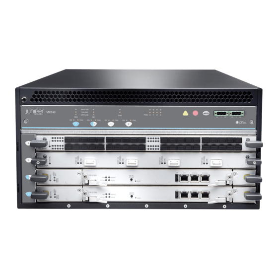
Page 32: Figure 1: Front View Of A Fully Configured Routers Chassis
MX240 3D Universal Edge Router Hardware Guide Figure 1: Front View of a Fully Configured Routers Chassis Figure 2: Rear View of a Fully Configured AC-Powered Routers Chassis (110 V) Copyright © 2013, Juniper Networks, Inc. -
Page 33: Mx240 Midplane Description
Figure 3: Rear View of a Fully Configured AC-Powered Routers Chassis (220 V) Figure 4: Rear View of a Fully Configured DC-Powered Routers Chassis Related MX240 Router Physical Specifications on page 257 Documentation MX240 Router Overview on page 3 MX240 Midplane Description... -
Page 34: Mx240 Dense Port Concentrator (Dpc) Overview
MX240 Router Overview on page 3 Documentation MX240 Chassis Description on page 7 MX240 Dense Port Concentrator (DPC) Description on page 10 MX240 Switch Control Board (SCB) Description on page 27 MX240 Flexible PIC Concentrator (FPC) Description on page 15... -
Page 35: Figure 6: Typical Dpcs Supported On The Mx240 Router
If a slot is not occupied by a DPC or an SCB, a blank panel must be installed to shield the empty slot and to allow cooling air to circulate properly through the router. Figure 6 on page 11 shows typical DPCs supported on the MX240 router. For more information about DPCs, see the MX Series Interface Module Reference... -
Page 36: Dpc Components
Two LEDs, located on the craft interface above the DPC, display the status of the DPC and are labeled FAIL Related DPC and MPC LEDs on the MX240 Craft Interface on page 40 Documentation MX240 Field-Replaceable Units (FRUs) on page 151 Replacing an MX240 DPC on page 180... -
Page 37: Mx240 Dpc Port And Interface Numbering
Ethernet interface so—SONET/SDH interface xe—10-Gigabit Ethernet interface For a complete list of media types, see Interface Naming Overview. fpc—Slot in which the DPC is installed. On the MX240 router, the DPCs are represented in the CLI as FPC 1 FPC 2 pic—Logical ports on the DPC. -
Page 38: Figure 8: Mx240 Dpc Interface Port Mapping
Related MX240 Router Hardware and CLI Terminology Mapping on page 4 Documentation Copyright © 2013, Juniper Networks, Inc. -
Page 39: Mx240 Flexible Pic Concentrator (Fpc) Overview
Chapter 2: MX240 Hardware Components MX240 Flexible PIC Concentrator (FPC) Overview MX240 Flexible PIC Concentrator (FPC) Description on page 15 MX240 Flexible PIC Concentrator (FPC) LEDs on page 16 FPCs Supported by the MX240 Router on page 17 MX240 Flexible PIC Concentrator (FPC) Description A Flexible PIC Concentrator (FPC) occupies two DPC slots on an MX Series router. -
Page 40: Fpc Components
FPC, are enabled. Forwarding continues uninterrupted during this process. When you remove or install an FPC, packet forwarding between other DPCs or FPCs is not affected. Figure 10: FPC Installed in the MX240 Router Chassis SC B SC B... -
Page 41: Fpcs Supported By The Mx240 Router
Maintaining MX240 FPCs on page 124 Troubleshooting the MX240 FPCs on page 145 FPCs Supported by the MX240 Router An FPC occupies two slots when installed in an MX Series router. The MX240 router supports up to one FPC. Table 4 on page 17 lists FPCs supported by MX Series routers. -
Page 42: Mx240 Pic Leds
Ethernet interface For a complete list of media types, see Interface Naming Overview. fpc—Lowest slot number in which the FPC is installed. On the MX240 router, the FPC is represented in the CLI as FPC 0 FPC 1 pic—PIC number, 0 or 1 depending on the FPC slot. -
Page 43: Figure 11: Mx240 Pic Interface Port Mapping
), that correspond to the four ports located on the PIC. coc12 user@host>show interfaces terse coc12-1/0/0 lc-1/0/0 lc-1/0/0.32769 vpls pfe-1/0/0 pfe-1/0/0.16383 inet inet6 pfh-1/0/0 pfh-1/0/0.16383 inet coc12-1/0/1 coc12-1/0/2 coc12-1/0/3 Related MX240 Router Hardware and CLI Terminology Mapping on page 4 Documentation Copyright © 2013, Juniper Networks, Inc. -
Page 44: Mx240 Modular Port Concentrator (Mpc) Overview
MPCs interface with the power supplies and Switch Control Boards (SCBs). You must install redundant SCBs to support full line-rate. The MX240 router supports up to three MPCs. You must install a high-capacity fan tray to use an MPC. For power requirements, see “Calculating Power Requirements for MX240... -
Page 45: Mpc Components
Chapter 2: MX240 Hardware Components Figure 12: Typical MPC Supported on the MX240 Router MPC (empty) Figure 13: MPC Installed Horizontally in the MX240 Router SC B SC B MPC Components Each MPC consists of the following components: MPC card carrier, which includes two MIC slots (excludes the fixed configuration MPC). -
Page 46: Mx240 Modular Port Concentrator (Mpc) Leds
. For more information about the line card LEDs on the craft interface, see “DPC and MPC LEDs on the MX240 Craft Interface” on page Each MPC also has LEDs located on the faceplate. For more information about LEDs on the MPC faceplate, see the “LEDs”... -
Page 47: Mx240 Modular Interface Card (Mic) Leds
MPC. Related MICs Supported by MX Series Routers Documentation MX240 Modular Interface Card (MIC) LEDs on page 23 Replacing an MX240 MIC on page 197 Maintaining MX240 MICs on page 127 MX240 Modular Interface Card (MIC) LEDs Each MIC has LEDs located on the faceplate. For more information about LEDs on the MIC faceplate, see the “LEDs”... - Page 48 MX240 3D Universal Edge Router Hardware Guide For a complete list of media types, see Interface Naming Overview. fpc—Slot in which the MPC is installed. On the MX240 router, the MPCs are represented in the CLI as through FPC 0 FPC 2 pic—Logical PIC on the MIC, numbered 0 or 1 when installed in MIC slot 0 and 2 or 3...
-
Page 49: Figure 14: Mx240 Mic Interface Port Mapping
Chapter 2: MX240 Hardware Components Figure 14: MX240 MIC Interface Port Mapping The MIC contains two logical PICs, numbered PIC 0 through PIC 1 in the CLI. Each logical PIC contains 10 ports numbered through The following sample CLI output displays a 20-port Gigabit Ethernet MIC with SFP (... -
Page 50: Mx240 Host Subsystem Overview
Related MX240 Router Hardware and CLI Terminology Mapping on page 4 Documentation MX240 Host Subsystem Overview MX240 Host Subsystem Description on page 26 MX240 Host Subsystem LEDs on page 27 MX240 Host Subsystem Description The host subsystem provides the routing and system management functions of the router. -
Page 51: Mx240 Host Subsystem Leds
Each host subsystem has three LEDs that display its status. The host subsystem LEDs are located in the middle of the craft interface. Related Host Subsystem LEDs on the MX240 Craft Interface on page 39 Documentation Maintaining the MX240 Host Subsystem on page 120... -
Page 52: Scb Slots
MX240 3D Universal Edge Router Hardware Guide Figure 15: SCB SCB Slots You can install one or two SCBs. The SCBs install horizontally into the front of the chassis in the slots labeled (the multifunction slot can contain either SCB1, DPC0, MPC0, or FPC0). -
Page 53: Mx240 Scb Leds
Ethernet transport markets that require higher-capacity traffic support demanding greater interface density (slot and capacity scale), as well as improved services. The upgraded SCB is supported on MX960, MX480, and MX240 routers. Some key attributes of the Enhanced MX SCB are:... -
Page 54: Mx Scbe Slots
MX240 3D Universal Edge Router Hardware Guide 160 Gbps/slot bandwidth with redundant fabric support, and improved fabric performance by using the next-generation fabric (XF) chip A central clocking module and a centralized clocking architecture that supports clock cleanup and distribution. The Stratum 3 clock module performs clock monitoring,... -
Page 55: Mx Scbe Components
Power circuits for the Routing Engine and SCBE LEDs—Provide status of the SCBE and clocking interface Related MX240 Switch Control Board (SCB) Description on page 27 Documentation MX240 Enhanced Switch Control Board LEDs on page 31 Upgrading an MX240 SCB on page 167... -
Page 56: Mx240 Routing Engine Overview
UTI clocking interface has failed. – UTI clocking interface is offline. Related MX240 Enhanced Switch Control Board Description on page 29 Documentation MX240 Host Subsystem Description on page 26 Upgrading an MX240 SCB on page 167 MX240 Routing Engine Overview... -
Page 57: Mx240 Routing Engine Description
If the master Routing Engine fails or is removed and the backup is configured appropriately, the backup takes over as the master. The Backup Routing Engine is hot-insertable and hot-removable. The MX240 router supports the RE-S-1300-2048, EE-S-2000-4096, and RE-S-1800 Routing Engines. NOTE: If two Routing Engines are installed, they must both be the same hardware model. -
Page 58: Routing Engine Components
Documentation Removing an MX240 Routing Engine on page 174 Installing an MX240 Routing Engine on page 176 MX240 Routing Engine Serial Number Label on page 301 RE-S-1800 Routing Engine Description for MX Series Figure 19 on page 35 shows the Routing Engine 1800. -
Page 59: Re-S-1800 Routing Engine Components
Chapter 2: MX240 Hardware Components Figure 19: RE-S-1800 Front View Auxiliary Ethernet port port slot 1 slot 2 Extractor clip Console Reset port port button Extractor clip RE-S-1800 Routing Engine Components on page 35 RE-S-1800 Routing Engine Boot Sequence on page 36... -
Page 60: Re-S-1800 Routing Engine Boot Sequence
MX240 3D Universal Edge Router Hardware Guide Reset button—Reboots the Routing Engine when pressed. Online/Offline button—Takes the Routing Engine online or offline when pressed. Extractor clips—Used for inserting and extracting the Routing Engine. Captive screws—Secure the Routing Engine in place. -
Page 61: Re-S-1800 Routing Engine Leds
MX240 Craft Interface Description MX240 Craft Interface Overview on page 37 MX240 Alarm LEDs and Alarm Cutoff/Lamp Test Button on page 38 MX240 Component LEDs on the Craft Interface on page 39 MX240 Alarm Relay Contacts on the Craft Interface on page 41... -
Page 62: Mx240 Alarm Leds And Alarm Cutoff/Lamp Test Button
At least one SCB must be installed in the router for the craft interface to obtain power. Related MX240 Alarm LEDs and Alarm Cutoff/Lamp Test Button on page 38 Documentation MX240 Alarm Relay Contacts on the Craft Interface on page 41... -
Page 63: Mx240 Component Leds On The Craft Interface
MX240 Alarm Relay Contacts on the Craft Interface on page 41 MX240 Component LEDs on the Craft Interface on page 39 Connecting the Alarm Relay Wires to the MX240 Craft Interface on page 158 MX240 Component LEDs on the Craft Interface... -
Page 64: Power Supply Leds On The Mx240 Craft Interface
Power supply is functioning normally. On steadily Power supply has failed or power input has failed. DPC and MPC LEDs on the MX240 Craft Interface Each DPC or MPC has LEDs on the craft interface that indicate its status. The LEDs, labeled... -
Page 65: Scb Leds On The Mx240 Craft Interface
Related MX240 Craft Interface Overview on page 37 Documentation MX240 Alarm LEDs and Alarm Cutoff/Lamp Test Button on page 38 MX240 Alarm Relay Contacts on the Craft Interface on page 41 MX240 Alarm Relay Contacts on the Craft Interface The craft interface has two alarm relay contacts for connecting the router to external... -
Page 66: Mx240 Power Supplies Description
MX240 DC Power Supply LEDs on page 47 MX240 Power System Overview The MX240 router uses either AC or DC power supplies. You can configure the MX240 router with either one or two high-line (220 V) AC power supplies, two or four low-line (110 V) AC power supplies, or one or two DC power supplies. -
Page 67: Mx240 Ac Power Supply Description
Chapter 2: MX240 Hardware Components MX240 DC Power Supply Description on page 45 Troubleshooting the MX240 Power System on page 149 MX240 AC Power Supply Description Each AC power supply weighs approximately 5.0 lb (2.3 kg) and consists of one AC appliance inlet, one AC input switch, a fan, and LEDs to monitor the status of the power supply. -
Page 68: Ac Power Supply Configurations
In the high-line (220 V) AC power configuration, the MX240 router contains one or two AC power supplies, located horizontally at the rear of the chassis in slots PEM0 (left to right). -
Page 69: Mx240 Dc Power Supply Description
Related MX240 Chassis Description on page 7 Documentation Power Supply LEDs on the MX240 Craft Interface on page 40 MX240 AC Power Supply Description on page 43 Connecting Power to an AC-Powered MX240 Router with Normal-Capacity Power Supplies on page 101... -
Page 70: Dc Power Supply Configurations
Do not set the input mode switch if the power supply is installed in the chassis. If the power supply is already installed, you must remove it before setting the input mode switch. Related MX240 DC Power Supply LEDs on page 47 Documentation Copyright © 2013, Juniper Networks, Inc. -
Page 71: Mx240 Dc Power Supply Leds
Supplies on page 104 MX240 Chassis Grounding Specifications on page 270 DC Power Supply Electrical Specifications for the MX240 Router on page 276 MX240 DC Power Supply LEDs Each DC power supply faceplate contains three LEDs that indicate the status of the... -
Page 72: Mx240 Cooling System Overview
MX240 3D Universal Edge Router Hardware Guide MX240 Cooling System Overview MX240 Cooling System Description on page 48 MX240 Fan LED on page 49 MX240 Cooling System Description The cooling system consists of the following components: Fan tray Air filter... -
Page 73: Mx240 Fan Led
Related MX240 Chassis Description on page 7 Documentation Troubleshooting the MX240 Cooling System on page 144 MX240 Fan LED Each fan has an LED that displays its status. The fan LEDs are located on the top left of the craft interface. For more information, see “Fan LED on the MX240 Craft Interface”... - Page 74 MX240 3D Universal Edge Router Hardware Guide Copyright © 2013, Juniper Networks, Inc.
-
Page 75: Setting Up The Mx240 Router
Unpacking the MX240 Router on page 61 Installing the MX240 Router Mounting Hardware on page 65 Installing the MX240 Router with a Mechanical Lift on page 69 Installing the MX240 Router Without a Mechanical Lift on page 81 Connecting the MX240 Router on page 93... - Page 76 MX240 3D Universal Edge Router Hardware Guide Copyright © 2013, Juniper Networks, Inc.
-
Page 77: Mx240 Router Installation Overview
Verifying the MX240 Router Parts Received on page 63 Install the mounting hardware. Installing the MX240 Router Mounting Hardware for a Rack or Cabinet on page 65 Moving the Mounting Brackets for Center-Mounting the MX240 Router on page 67 Lift the router on to the rack. Because of the weight of the router, we recommend that you use a mechanical lift. - Page 78 MX240 3D Universal Edge Router Hardware Guide Power on the router: Perform the initial system configuration as described in “Initially Configuring the MX240 Router” on page 111. Related Definition of Safety Warning Levels on page 221 Documentation MX240 Router Physical Specifications on page 257...
-
Page 79: Preparing The Site For Mx240 Router Installation
Preparing the Site for MX240 Router Installation MX240 Site Preparation Checklist on page 55 MX240 Router Rack Requirements on page 56 MX240 Router Clearance Requirements for Airflow and Hardware Maintenance on page 58 MX240 Router Cabinet Requirements on page 59 MX240 Site Preparation Checklist... -
Page 80: Mx240 Router Rack Requirements
Related MX240 Router Rack Requirements on page 56 Documentation MX240 Router Clearance Requirements for Airflow and Hardware Maintenance on page 58 MX240 Router Rack Requirements The router can be installed in many types of racks, including four-post (telco) racks and open-frame racks. - Page 81 Cabinets, Racks, Panels, and Associated Equipment (document number EIA-310-D) published by the Electronics Industry Association. You can stack several MX240 Router units in a rack that has sufficient usable vertical space. The rack must be strong enough to support the weight of the fully configured router, up to 128 lb (58.1 kg).
-
Page 82: Maintenance
MX240 3D Universal Edge Router Hardware Guide Figure 30: Typical Open-Frame Rack Related Installing the MX240 Router Mounting Hardware for a Rack or Cabinet on page 65 Documentation Installation Safety Warnings for Juniper Networks Devices on page 228 MX240 Router Clearance Requirements for Airflow and Hardware Maintenance... -
Page 83: Mx240 Router Cabinet Requirements
Figure 31: Chassis Dimensions and Clearance Requirements Related MX240 Router Cabinet Size and Clearance Requirements on page 59 Documentation MX240 Router Cabinet Airflow Requirements on page 60 MX240 Router Cabinet Requirements... -
Page 84: Mx240 Router Cabinet Airflow Requirements
Route and dress all cables to minimize the blockage of airflow to and from the chassis. Figure 32: Airflow Through Chassis Related MX240 Router Clearance Requirements for Airflow and Hardware Maintenance on Documentation page 58 MX240 Router Cabinet Size and Clearance Requirements on page 59... -
Page 85: Unpacking The Mx240 Router
CHAPTER 5 Unpacking the MX240 Router Tools and Parts Required to Unpack the MX240 Router on page 61 Unpacking the MX240 Router on page 61 Verifying the MX240 Router Parts Received on page 63 Tools and Parts Required to Unpack the MX240 Router... -
Page 86: Figure 33: Contents Of The Shipping Crate
Figure 33: Contents of the Shipping Crate Related Tools and Parts Required to Unpack the MX240 Router on page 61 Documentation Verifying the MX240 Router Parts Received on page 63 Installing the MX240 Router Using a Mechanical Lift on page 74 Installing the MX240 Chassis in the Rack Manually on page 86 Copyright ©... -
Page 87: Verifying The Mx240 Router Parts Received
Chapter 5: Unpacking the MX240 Router Verifying the MX240 Router Parts Received A packing list is included in each shipment. Check the parts in the shipment against the items on the packing list. The packing list specifies the part numbers and descriptions of each part in your order. -
Page 88: Table 21: Accessory Box Parts List
Ethernet cable, RJ-45/RJ-45, 4-pair stranded UTP, Category 5E, 15' ESD wrist strap with cable Related Tools and Parts Required to Unpack the MX240 Router on page 61 Documentation Unpacking the MX240 Router on page 61 Copyright © 2013, Juniper Networks, Inc. -
Page 89: Installing The Mx240 Router Mounting Hardware
Installing the MX240 Router Mounting Hardware Installing the MX240 Router Mounting Hardware for a Rack or Cabinet on page 65 Moving the Mounting Brackets for Center-Mounting the MX240 Router on page 67 Installing the MX240 Router Mounting Hardware for a Rack or Cabinet The router can be installed in a four-post rack or cabinet or an open-frame rack. -
Page 90: Figure 34: Installing The Front Mounting Hardware For A Four-Post Rack Or
MX240 3D Universal Edge Router Hardware Guide Install the small shelf on the back of the rack rails. Rest the bottom slot of each flange on a mounting screw. Partially insert the remaining screws into the open holes in each flange of the small... -
Page 91: Moving The Mounting Brackets For Center-Mounting The Mx240 Router
Chapter 6: Installing the MX240 Router Mounting Hardware Figure 35: Installing the Mounting Hardware for an Open-Frame Rack Related Moving the Mounting Brackets for Center-Mounting the MX240 Router on page 67 Documentation Installing the MX240 Router Using a Mechanical Lift on page 74... - Page 92 Tighten the two screws completely. Repeat the procedure for the other bracket. Related Installing the MX240 Router Mounting Hardware for a Rack or Cabinet on page 65 Documentation Installing the MX240 Router Using a Mechanical Lift on page 74 Installing the MX240 Chassis in the Rack Manually on page 86...
-
Page 93: Installing The Mx240 Router With A Mechanical Lift
Lift on page 69 Installing the MX240 Router Using a Mechanical Lift on page 74 Reinstalling Components in the MX240 Router After Installing it With a Lift on page 76 Tools Required to Install the MX240 Router with a Mechanical Lift... -
Page 94: Lift
MX240 3D Universal Edge Router Hardware Guide Removing the SCBs Before Installing the MX240 Router With a Lift on page 71 Removing the DPCs Before Installing the MX240 Router With a Lift on page 72 Removing the FPC Before Installing the MX240 Router With a Lift on page 73 Removing the Power Supplies Before Installing the MX240 Router With a Lift Remove the leftmost power supply first and then work your way to the right. -
Page 95: Removing The Scbs Before Installing The Mx240 Router With A Lift
Chapter 7: Installing the MX240 Router with a Mechanical Lift Figure 37: Removing the Fan Tray Removing the SCBs Before Installing the MX240 Router With a Lift To remove the SCBs (see Figure 38 on page 72): Place an electrostatic bag or antistatic mat on a flat, stable surface. -
Page 96: Removing The Dpcs Before Installing The Mx240 Router With A Lift
MX240 3D Universal Edge Router Hardware Guide Figure 38: Removing an SCB Removing the DPCs Before Installing the MX240 Router With a Lift To remove a DPC (see Figure 39 on page 73): Have ready an antistatic mat for the DPC. Also have ready rubber safety caps for each DPC using an optical interface on the DPC that you are removing. -
Page 97: Removing The Fpc Before Installing The Mx240 Router With A Lift
Chapter 7: Installing the MX240 Router with a Mechanical Lift Figure 39: Removing a DPC Removing the FPC Before Installing the MX240 Router With a Lift To remove an FPC (see Figure 40 on page 74): Attach an electrostatic discharge (ESD) grounding strap to your bare wrist and connect the strap to an approved site ESD grounding point. -
Page 98: Installing The Mx240 Router Using A Mechanical Lift
Documentation Installing the MX240 Router Using a Mechanical Lift on page 74 Reinstalling Components in the MX240 Router After Installing it With a Lift on page 76 Installing the MX240 Router Using a Mechanical Lift Because of the router's size and weight—up to 128 lb (58.1 kg) depending on the configuration—we strongly recommend that you install the router using a mechanical... -
Page 99: Figure 41: Installing The Router In The Rack
Tools Required to Install the MX240 Router with a Mechanical Lift on page 69 Removing Components from the MX240 Router Before Installing It With a Lift on page 69 Reinstalling Components in the MX240 Router After Installing it With a Lift on page 76 Copyright © 2013, Juniper Networks, Inc. -
Page 100: Reinstalling Components In The Mx240 Router After Installing It With A Lift
Reinstalling the Power Supplies After Installing the MX240 Router With a Lift on page 76 Reinstalling the Fan Tray After Installing the MX240 Router With a Lift on page 77 Reinstalling the SCBs After Installing the MX240 Router With a Lift on page 77... -
Page 101: Reinstalling The Fan Tray After Installing The Mx240 Router With A Lift
Chapter 7: Installing the MX240 Router with a Mechanical Lift Reinstalling the Fan Tray After Installing the MX240 Router With a Lift To reinstall the fan tray (see Figure 43 on page 77): Attach an electrostatic discharge (ESD) grounding strap to your bare wrist, and connect the strap to one of the ESD points on the chassis. -
Page 102: Reinstalling The Dpcs After Installing The Mx240 Router With A Lift
To avoid blocking the visibility of the LEDs position the ejectors over the PARK icon. Figure 44: Reinstalling an SCB Reinstalling the DPCs After Installing the MX240 Router With a Lift To reinstall a DPC (see Figure 45 on page... -
Page 103: Reinstalling The Fpcs After Installing The Mx240 Router With A Lift
Chapter 7: Installing the MX240 Router with a Mechanical Lift Figure 45: Reinstalling a DPC Reinstalling the FPCs After Installing the MX240 Router With a Lift To reinstall a DPC (see Figure 46 on page 79): Attach an electrostatic discharge (ESD) grounding strap to your bare wrist, and connect the strap to one of the ESD points on the chassis. - Page 104 MX240 3D Universal Edge Router Hardware Guide Related Tools Required to Install the MX240 Router with a Mechanical Lift on page 69 Documentation Removing Components from the MX240 Router Before Installing It With a Lift on page 69 Installing the MX240 Router Using a Mechanical Lift on page 74 Preventing Electrostatic Discharge Damage to an MX240 Router on page 226 Copyright ©...
-
Page 105: Installing The Mx240 Router Without A Mechanical Lift
CHAPTER 8 Installing the MX240 Router Without a Mechanical Lift Tools Required to Install the MX240 Router Without a Mechanical Lift on page 81 Removing Components from the MX240 Router Before Installing It Without a Lift on page 81 Installing the MX240 Chassis in the Rack Manually on page 86... -
Page 106: Removing The Power Supplies Before Installing The Mx240 Router Without
Removing the Power Supplies Before Installing the MX240 Router Without a Lift on page 82 Removing the Fan Tray Before Installing the MX240 Router Without a Lift on page 82 Removing the SCBs Before Installing the MX240 Router Without a Lift on page 83... -
Page 107: Removing The Scbs Before Installing The Mx240 Router Without A Lift
Place one hand under the fan tray to support it, and pull the fan tray completely out of the chassis. Figure 48: Removing the Fan Tray Removing the SCBs Before Installing the MX240 Router Without a Lift To remove the SCBs (see Figure 49 on page 84): Place an electrostatic bag or antistatic mat on a flat, stable surface. -
Page 108: Removing The Dpcs Before Installing The Mx240 Router Without A Lift
MX240 3D Universal Edge Router Hardware Guide Figure 49: Removing an SCB Removing the DPCs Before Installing the MX240 Router Without a Lift To remove a DPC (see Figure 50 on page 85): Have ready an antistatic mat for the DPC. Also have ready rubber safety caps for each DPC using an optical interface on the DPC that you are removing. -
Page 109: Removing The Fpc Before Installing The Mx240 Router Without A Lift
Chapter 8: Installing the MX240 Router Without a Mechanical Lift Figure 50: Removing a DPC Removing the FPC Before Installing the MX240 Router Without a Lift To remove an FPC (see Figure 51 on page 86): Attach an electrostatic discharge (ESD) grounding strap to your bare wrist, and connect the strap to an approved site ESD grounding point. -
Page 110: Installing The Mx240 Chassis In The Rack Manually
Tools and Parts Required to Replace MX240 Hardware Components on page 152 Documentation Installing the MX240 Chassis in the Rack Manually on page 86 Reinstalling Components in the MX240 Router After Installing It Without a Lift on page 88 Preventing Electrostatic Discharge Damage to an MX240 Router on page 226... -
Page 111: Figure 52: Installing The Router In The Rack
For an illustration of the mounting hardware required for a four-post rack or cabinet, see Figure 34 on page Related MX240 Site Preparation Checklist on page 55 Documentation Tools Required to Install the MX240 Router Without a Mechanical Lift on page 81 Copyright © 2013, Juniper Networks, Inc. -
Page 112: Lift
Reinstalling the Power Supplies After Installing the MX240 Router Without a Lift on page 88 Reinstalling the Fan Tray After Installing the MX240 Router Without a Lift on page 89 Reinstalling the SCBs After Installing the MX240 Router Without a Lift on page 90... -
Page 113: Lift
Chapter 8: Installing the MX240 Router Without a Mechanical Lift Figure 53: Reinstalling a Power Supply Reinstalling the Fan Tray After Installing the MX240 Router Without a Lift To reinstall the fan tray (see Figure 54 on page 89): Attach an electrostatic discharge (ESD) grounding strap to your bare wrist, and connect the strap to one of the ESD points on the chassis. -
Page 114: Reinstalling The Scbs After Installing The Mx240 Router Without A Lift
MX240 3D Universal Edge Router Hardware Guide Reinstalling the SCBs After Installing the MX240 Router Without a Lift To reinstall an SCB (see Figure 55 on page 90): CAUTION: Before removing or replacing an SCB, ensure that the ejector handles are stored vertically and pressed toward the center of the SCB. -
Page 115: Reinstalling The Fpcs After Installing The Mx240 Router Without A Lift
Grasp both ejector handles and rotate them clockwise simultaneously until the DPC is fully seated. Figure 56: Reinstalling a DPC Reinstalling the FPCs After Installing the MX240 Router Without a Lift To reinstall a DPC (see Figure 57 on page... -
Page 116: Figure 57: Reinstalling An Fpc
Figure 57: Reinstalling an FPC SC B SC B Related Tools Required to Install the MX240 Router Without a Mechanical Lift on page 81 Documentation Removing Components from the MX240 Router Before Installing It Without a Lift on page 81... -
Page 117: Connecting The Mx240 Router
Tools and Parts Required for MX240 Router Connections on page 93 Connecting the MX240 Router to Management and Alarm Devices on page 93 Connecting DPC, MPC, MIC, or PIC Cables to the MX240 Router on page 96 Tools and Parts Required for MX240 Router Connections... -
Page 118: Device
Plug the other end of the cable into the network device. Figure 58: Ethernet Port Figure 59: Routing Engine Ethernet Cable Connector Connecting the MX240 Router to a Management Console or Auxiliary Device To use a system console to configure and manage the Routing Engine, connect it to the appropriate port on the Routing Engine. -
Page 119: Connecting The Mx240 Router To An External Alarm-Reporting Device
Figure 60: Auxiliary and Console Ports Figure 61: Routing Engine Console and Auxiliary Cable Connector Connecting the MX240 Router to an External Alarm-Reporting Device To connect the router to external alarm-reporting devices, attach wires to the relay contacts on the craft interface. (See Figure 62 on page 95.) A system... -
Page 120: Connecting Dpc, Mpc, Mic, Or Pic Cables To The Mx240 Router
Tools and Parts Required for MX240 Router Connections on page 93 Documentation Connecting DPC, MPC, MIC, or PIC Cables to the MX240 Router on page 96 Connecting the Alarm Relay Wires to the MX240 Craft Interface on page 158 Routing Engine Interface Cable and Wire Specifications for MX Series Routers on... -
Page 121: Figure 63: Attaching A Cable To A Dpc
Figure 63: Attaching a Cable to a DPC Figure 64: Attaching a Cable to a MIC Fiber-optic cable Related Connecting the MX240 Router to Management and Alarm Devices on page 93 Documentation Installing an MX240 DPC on page 182 Installing an MX240 PIC on page 190... - Page 122 MX240 3D Universal Edge Router Hardware Guide Copyright © 2013, Juniper Networks, Inc.
-
Page 123: Grounding And Providing Power To The Mx240 Router
Powering On a DC-Powered MX240 Router on page 108 Powering Off the MX240 Router on page 110 Tools and Parts Required for MX240 Router Grounding and Power Connections To ground and provide power to the router, you need the following tools and parts: Phillips (+) screwdrivers, numbers 1 and 2 2.5-mm flat-blade (–) screwdriver... -
Page 124: Grounding The Mx240 Router
Dress the grounding cable and verify that it does not touch or block access to router components, and that it does not drape where people could trip on it. Related Tools and Parts Required for MX240 Router Grounding and Power Connections on Documentation page 99... -
Page 125: Power Supplies
Chapter 10: Grounding and Providing Power to the MX240 Router Connecting Power to an AC-Powered MX240 Router with Normal-Capacity Power Supplies CAUTION: Do not mix AC and DC power supplies within the same router. Damage to the router might occur. -
Page 126: Installing The Mx240 Ac High-Capacity Power Supplies
Documentation Disconnecting an MX240 AC Power Supply Cord on page 215 Preventing Electrostatic Discharge Damage to an MX240 Router on page 226 AC Power Cord Specifications for the MX240 Router on page 273 Installing the MX240 AC High-Capacity Power Supplies... -
Page 127: Powering On An Ac-Powered Mx240 Router
Chapter 10: Grounding and Providing Power to the MX240 Router Figure 66: Installing a High-Capacity AC Power Supply Powering On an AC-Powered MX240 Router To power on an AC-powered router: Verify that the power supplies are fully inserted in the chassis. -
Page 128: Supplies
On the external management device connected to the Routing Engine, monitor the startup process to verify that the system has booted properly. Related Connecting the MX240 Router to Management and Alarm Devices on page 93 Documentation Replacing an MX240 AC Power Supply Cord on page 214... - Page 129 Chapter 10: Grounding and Providing Power to the MX240 Router To connect the DC source power cables to the router for each power supply: Switch off the dedicated customer site circuit breakers. Ensure that the voltage across the DC power source cable leads is 0 V and that there is no chance that the cable leads might become active during installation.
-
Page 130: Figure 67: Connecting Dc Power To The Router
Figure 67: Connecting DC Power to the Router Related Powering On a DC-Powered MX240 Router on page 108 Documentation Preventing Electrostatic Discharge Damage to an MX240 Router on page 226 DC Power Cable Specifications for the MX240 Router on page 279 Copyright © 2013, Juniper Networks, Inc. -
Page 131: Installing An Mx240 Dc High-Capacity Power Supply
Chapter 10: Grounding and Providing Power to the MX240 Router Installing an MX240 DC High-Capacity Power Supply To install a DC power supply: Ensure that the voltage across the DC power source cable leads is 0 V and that there is no chance that the cable leads might become active during installation. -
Page 132: Powering On A Dc-Powered Mx240 Router
MX240 3D Universal Edge Router Hardware Guide CAUTION: Ensure that each power cable lug seats flush against the surface of the terminal block as you are tightening the nuts. Ensure that each nut is properly threaded onto the terminal stud. The nut should be able to spin freely with your fingers when it is first placed onto the terminal stud. - Page 133 Chapter 10: Grounding and Providing Power to the MX240 Router Verify that the power supplies are fully inserted in the chassis. Verify that the source power cables are connected to the appropriate terminal: the positive (+) source cable to the return terminal (labeled ) and the negative (–)
-
Page 134: Powering Off The Mx240 Router
MX240 3D Universal Edge Router Hardware Guide Related Connecting the MX240 Router to Management and Alarm Devices on page 93 Documentation Replacing an MX240 DC Power Supply Cable on page 215 Preventing Electrostatic Discharge Damage to an MX240 Router on page 226... -
Page 135: Configuring Junos Os
The MX240 router is shipped with the Junos OS preinstalled and ready to be configured when the MX240 router is powered on. There are three copies of the software: one on a CompactFlash card in the Routing Engine, one on a rotating hard disk in the Routing Engine, and one on a USB flash drive that can be inserted into the slot in the Routing Engine faceplate. - Page 136 MX240 3D Universal Edge Router Hardware Guide Start the CLI. root# cli root@> Enter configuration mode. cli> configure [edit] root@# Configure the name of the router. If the name includes spaces, enclose the name in quotation marks (“ ”). [edit] root@# set system host-name host-name Create a management console user account.
- Page 137 (Optional) Configure additional properties by adding the necessary configuration statements. Then commit the changes to activate them on the router. [edit] root@host# commit When you have finished configuring the router, exit configuration mode. Copyright © 2013, Juniper Networks, Inc.
- Page 138 If the router boots from an alternate boot device, the Junos OS displays a message indication this when you log in to the router. Related Powering On an AC-Powered MX240 Router on page 103 Documentation Powering On a DC-Powered MX240 Router on page 108...
- Page 139 PART 3 Hardware Maintenance, Troubleshooting, and Replacement Procedures Maintaining MX240 Router Hardware Components on page 117 Troubleshooting MX240 Hardware Components on page 141 Replacing MX240 Hardware Components on page 151 Copyright © 2013, Juniper Networks, Inc.
- Page 140 MX240 3D Universal Edge Router Hardware Guide Copyright © 2013, Juniper Networks, Inc.
-
Page 141: Maintaining Mx240 Router Hardware Components
This chapter describes how to maintain hardware components installed in the router. Some components, such as the craft interface, require no maintenance. For information about returning a part to Juniper Networks for repair or replacement, see “Contacting Customer Support and Returning MX240 Hardware” on page 291. -
Page 142: Maintaining The Mx240 Cooling System Components
Do not run the router for more than a few minutes without the air filter in place. Related Maintaining the MX240 Air Filter on page 118 Documentation Maintaining the MX240 Fan Tray on page 118 Maintaining the MX240 Host Subsystem on page 120... - Page 143 Chapter 12: Maintaining MX240 Router Hardware Components the remaining fans to maintain proper cooling. A red alarm is triggered when a fan fails, and a yellow alarm and red alarm is triggered when a fan tray is removed. To display the status of the cooling system, issue the show chassis environment command.
-
Page 144: Maintaining The Mx240 Host Subsystem
MX240 3D Universal Edge Router Hardware Guide Related MX240 Cooling System Description on page 48 Documentation Troubleshooting the MX240 Cooling System on page 144 Replacing the MX240 Fan Tray on page 159 Maintaining the MX240 Host Subsystem Purpose For optimum router performance, verify the condition of the host subsystem. The host subsystem comprises an SCB and a Routing Engine installed into a slot in the SCB. - Page 145 Chapter 12: Maintaining MX240 Router Hardware Components Model RE-S-1300 Serial ID 1000694976 Start time 2007-06-19 14:17:00 PDT Uptime 20 days, 23 hours, 51 minutes, 4 seconds To check the status of the SCBs, issue the show chassis environment cb command.
-
Page 146: Maintaining Mx240 Packet Forwarding Engine Components
Maintaining MX240 MPCs on page 126 Maintaining MX240 MICs on page 127 Maintaining Cables that Connect to MX240 DPCs, MPCs, MICs, or PICs on page 128 Holding and Storing MX Series DPCs on page 129 Holding and Storing MX Series FPCs on page 133... - Page 147 Chapter 12: Maintaining MX240 Router Hardware Components Issue the CLI command to check the status of installed DPCs. As show chassis fpc shown in the sample output, the value in the column labeled indicates Online State that the DPC is functioning normally: user@host>...
-
Page 148: Maintaining Mx240 Fpcs
MX240 Dense Port Concentrator (DPC) Description on page 10 Documentation MX240 Dense Port Concentrator (DPC) LEDs on page 12 Maintaining Cables that Connect to MX240 DPCs, MPCs, MICs, or PICs on page 128 Troubleshooting the MX240 DPCs on page 144 Replacing an MX240 DPC on page 180... -
Page 149: Maintaining Mx240 Pics
For further description of the output from the command, see the Junos OS Operational Mode Commands. Related MX240 Flexible PIC Concentrator (FPC) LEDs on page 16 Documentation Holding an MX240 FPC on page 134 Storing an MX240 FPC on page 138... -
Page 150: Maintaining Mx240 Mpcs
MX240 PIC Description on page 17 Documentation Troubleshooting the MX240 PICs on page 147 Replacing an MX240 PIC on page 188 MX240 PIC Serial Number Label on page 296 Maintaining MX240 MPCs Purpose For optimum router performance, verify the condition of the Modular Port Concentrators (MPCs). -
Page 151: Maintaining Mx240 Mics
For further description of the output from the command, see the Junos OS Operational Mode Commands. Related MX240 Modular Port Concentrator (MPC) Description on page 20 Documentation MX240 Modular Port Concentrator (MPC) LEDs on page 22 Troubleshooting the MX240 MPCs on page 147... -
Page 152: Maintaining Cables That Connect To Mx240 Dpcs, Mpcs, Mics, Or Pics
Troubleshooting the MX240 MICs on page 148 Replacing an MX240 MIC on page 197 Maintaining Cables that Connect to MX240 DPCs, MPCs, MICs, or PICs Purpose For optimum router performance, verify the condition of the cables that connect to the DPCs, MPCs, MICs, or PICs. -
Page 153: Holding And Storing Mx Series Dpcs
Chapter 12: Maintaining MX240 Router Hardware Components frequent plugging and unplugging is then absorbed by the short fiber extension, which is easy and inexpensive to replace. Keep fiber-optic cable connections clean. Small microdeposits of oil and dust in the canal of the transceiver or cable connector could cause loss of light, reducing signal power and possibly causing intermittent problems with the optical connection. -
Page 154: Holding An Mx240 Dpc
MX240 3D Universal Edge Router Hardware Guide Figure 69: DPC Edges Related Maintaining MX240 DPCs on page 122 Documentation Holding an MX240 DPC on page 130 Storing an MX240 DPC on page 132 Troubleshooting the MX240 DPCs on page 144... -
Page 155: Figure 70: Do Not Grasp The Connector Edge
Chapter 12: Maintaining MX240 Router Hardware Components If the DPC is horizontal before you grasp it, place your left hand around the faceplate and your right hand along the bottom edge. To hold a DPC horizontally: Orient the DPC so that the faceplate faces you. -
Page 156: Storing An Mx240 Dpc
MX240 3D Universal Edge Router Hardware Guide Figure 71: Do Not Rest the DPC on an Edge If you must rest the DPC temporarily on an edge while changing its orientation between vertical and horizontal, use your hand as a cushion between the edge and the surface. -
Page 157: Holding And Storing Mx Series Fpcs
Chapter 12: Maintaining MX240 Router Hardware Components If you must insert the DPC into a bag by yourself, first lay the DPC horizontally on a flat, stable surface, sheet metal side down. Orient the DPC with the faceplate facing you. -
Page 158: Holding An Mx240 Fpc
Connector edge Faceplate Bottom edge Related MX240 Flexible PIC Concentrator (FPC) Description on page 15 Documentation MX240 Flexible PIC Concentrator (FPC) LEDs on page 16 Maintaining MX240 FPCs on page 124 Troubleshooting the MX240 FPCs on page 145 Replacing an MX240 FPC on page 184... -
Page 159: Figure 73: Do Not Grasp The Connector Edge
Chapter 12: Maintaining MX240 Router Hardware Components Figure 73: Do Not Grasp the Connector Edge Do not carry the FPC by the faceplate with only one hand (see Figure 74 on page 136). Copyright © 2013, Juniper Networks, Inc. -
Page 160: Figure 74: Do Not Carry An Fpc With Only One Hand
MX240 3D Universal Edge Router Hardware Guide Figure 74: Do Not Carry an FPC with Only One Hand Do not rest any edge of an FPC directly against a hard surface (see Figure 75 on page 136). If you must rest the FPC temporarily on an edge while changing its orientation between vertical and horizontal, use your hand as a cushion between the edge and the surface. -
Page 161: Figure 76: Holding An Fpc Vertically
Related MX240 FPC Terminology on page 133 Documentation Storing an MX240 FPC on page 138 Replacing an MX240 FPC on page 184 Tools and Parts Required to Replace MX240 Hardware Components on page 152 Copyright © 2013, Juniper Networks, Inc. -
Page 162: Storing An Mx240 Fpc
Documentation Holding an MX240 FPC on page 134 Replacing an MX240 FPC on page 184 Tools and Parts Required to Replace MX240 Hardware Components on page 152 Maintaining the MX240 Power Supplies Purpose For optimum router performance, verify the condition of the power supplies. - Page 163 Related Power Supply LEDs on the MX240 Craft Interface on page 40 Documentation MX240 AC Power Supply Description on page 43 MX240 DC Power Supply Description on page 45...
- Page 164 MX240 3D Universal Edge Router Hardware Guide Copyright © 2013, Juniper Networks, Inc.
-
Page 165: Troubleshooting Mx240 Hardware Components
CHAPTER 13 Troubleshooting MX240 Hardware Components Troubleshooting Resources for MX240 Routers on page 141 Troubleshooting the MX240 Cooling System on page 144 Troubleshooting the MX240 DPCs on page 144 Troubleshooting the MX240 FPCs on page 145 Troubleshooting the MX240 PICs on page 147... -
Page 166: Chassis And Interface Alarm Messages
MX240 3D Universal Edge Router Hardware Guide Chassis and Interface Alarm Messages When the Routing Engine detects an alarm condition, it lights the red or yellow alarm LED on the craft interface as appropriate. To view a more detailed description of the... -
Page 167: Component Leds
Power supply LEDs—Two LEDs on each power supply faceplate indicate the status of that power supply. Juniper Networks Technical Assistance Center If you need assistance during troubleshooting, you can contact the Juniper Networks Technical Assistance Center (JTAC) by using the Web or by telephone. For more information see “Contacting Customer Support”... -
Page 168: Troubleshooting The Mx240 Cooling System
The temperature of the router exceeds the maximum (“temperature hot”) threshold (red alarm and automatic shutdown of the power supplies). Related MX240 Alarm LEDs and Alarm Cutoff/Lamp Test Button on page 38 Documentation MX240 Cooling System Description on page 48... -
Page 169: Troubleshooting The Mx240 Fpcs
For further description of the output from the commands, see the Junos OS Administration Library for Routing Devices. Related MX240 Dense Port Concentrator (DPC) Description on page 10 Documentation Maintaining MX240 DPCs on page 122 Replacing an MX240 DPC on page 180... - Page 170 For further description of the output from the commands, see the Junos OS Administration Library for Routing Devices. Related MX240 Flexible PIC Concentrator (FPC) LEDs on page 16 Documentation Maintaining MX240 FPCs on page 124 Copyright © 2013, Juniper Networks, Inc.
-
Page 171: Troubleshooting The Mx240 Pics
MX240 PIC Description on page 17 Documentation Maintaining MX240 PICs on page 125 Replacing an MX240 PIC on page 188 MX240 PIC Serial Number Label on page 296 Troubleshooting the MX240 MPCs Problem The MPCs are not functioning normally. Solution... -
Page 172: Troubleshooting The Mx240 Mics
For further description of the output from the commands, see the Junos OS System Configuration Guide. Related MX240 Modular Port Concentrator (MPC) LEDs on page 22 Documentation Maintaining MX240 MPCs on page 126 Replacing an MX240 MPC on page 192... -
Page 173: Troubleshooting The Mx240 Power System
For further description of the output from the command, see the Junos OS Operational Mode Commands. Related MX240 Modular Interface Card (MIC) Description on page 22 Documentation Maintaining MX240 MICs on page 127 Replacing an MX240 MIC on page 197... - Page 174 MX240 DC Power Supply Description on page 45 Troubleshooting Resources for MX240 Routers on page 141 Replacing an MX240 AC Normal-Capacity Power Supply on page 208 Replacing an MX240 DC Normal-Capacity Power Supply on page 210 Copyright © 2013, Juniper Networks, Inc.
-
Page 175: Replacing Mx240 Hardware Components
Replacing an MX240 MIC on page 197 Replacing a Cable on an MX240 DPC, MPC, MIC, or PIC on page 203 Replacing an SFP or XFP Transceiver from an MX240 DPC, MPC, MIC, or PIC on page 206 Replacing MX240 Power System Components on page 208... -
Page 176: Tools And Parts Required To Replace Mx240 Hardware Components
Related MX240 Host Subsystem Description on page 26 Documentation Tools and Parts Required to Replace MX240 Hardware Components on page 152 Taking an MX240 Host Subsystem Offline on page 163 Tools and Parts Required to Replace MX240 Hardware Components To replace hardware components, you need the tools and parts listed in Table 24 on page 153. -
Page 177: Table 24: Tools And Parts Required To Replace Hardware Components
Chapter 14: Replacing MX240 Hardware Components Table 24: Tools and Parts Required to Replace Hardware Components Tool or Part Components 2.5-mm flat-blade (–) screwdriver Alarm relay terminal block 7/16-in. nut driver or socket wrench Cables and connectors DC power supply... -
Page 178: Replacing The Mx240 Air Filter
Replacing an MX240 DPC on page 180 Replacing an MX240 FPC on page 184 Replacing an MX240 PIC on page 188 Replacing an MX240 AC Normal-Capacity Power Supply on page 208 Replacing an MX240 DC Normal-Capacity Power Supply on page 210 Replacing the MX240 Air Filter... -
Page 179: Installing The Mx240 Air Filter
Chapter 14: Replacing MX240 Hardware Components To remove the air filter (see Figure 78 on page 155): Attach an electrostatic discharge (ESD) grounding strap to your bare wrist, and connect the strap to one of the ESD points on the chassis. -
Page 180: Replacing The Mx240 Craft Interface
Preventing Electrostatic Discharge Damage to an MX240 Router on page 226 Replacing the MX240 Craft Interface Disconnecting the Alarm Relay Wires from the MX240 Craft Interface on page 156 Removing the MX240 Craft Interface on page 157 Installing the MX240 Craft Interface on page 157... -
Page 181: Removing The Mx240 Craft Interface
Chapter 14: Replacing MX240 Hardware Components Figure 80: Alarm Relay Contacts Removing the MX240 Craft Interface To remove the craft interface (see Figure 81 on page 157): Attach an electrostatic discharge (ESD) grounding strap to your bare wrist, and connect the strap to one of the ESD points on the chassis. -
Page 182: Connecting The Alarm Relay Wires To The Mx240 Craft Interface
Attach the other end of the wires to the external device. Figure 83: Alarm Relay Contacts Related MX240 Craft Interface Overview on page 37 Documentation Preventing Electrostatic Discharge Damage to an MX240 Router on page 226 Copyright © 2013, Juniper Networks, Inc. -
Page 183: Replacing The Mx240 Fan Tray
Chapter 14: Replacing MX240 Hardware Components Replacing the MX240 Fan Tray Removing the MX240 Fan Tray on page 159 Installing the MX240 Normal-Capacity Fan Tray on page 160 Removing the MX240 Fan Tray NOTE: To prevent overheating, install the replacement fan tray immediately after removing the existing fan tray. -
Page 184: Installing The Mx240 Normal-Capacity Fan Tray
Figure 85: Installing the Fan Tray Related MX240 Cooling System Description on page 48 Documentation Preventing Electrostatic Discharge Damage to an MX240 Router on page 226 Installing the MX240 High-Capacity Fan Tray To install the fan tray (see Figure 86 on page... -
Page 185: Replacing Mx240 Host Subsystem Components
Figure 86: Reinstalling a Fan Tray Replacing MX240 Host Subsystem Components Effect of Taking the MX240 Host Subsystem Offline on page 161 Taking an MX240 Host Subsystem Offline on page 163 Operating and Positioning the MX240 SCB Ejectors on page 164... -
Page 186: Table 25: Effect Of Taking The Host Subsystem Offline
MX240 3D Universal Edge Router Hardware Guide Table 25: Effect of Taking the Host Subsystem Offline Type of Host Subsystem Effect of Taking the Host Subsystem Offline Nonredundant host The router shuts down. subsystem Backup host subsystem The functioning of the router is not interrupted. The backup host subsystem is hot-removable and hot-insertable. -
Page 187: Taking An Mx240 Host Subsystem Offline
Related MX240 Host Subsystem Description on page 26 Documentation Host Subsystem LEDs on the MX240 Craft Interface on page 39 Maintaining the MX240 Host Subsystem on page 120 Taking an MX240 Host Subsystem Offline on page 163 Taking an MX240 Host Subsystem Offline Before you take a host subsystem offline see “Effect of Taking the MX240 Host Subsystem... -
Page 188: Operating And Positioning The Mx240 Scb Ejectors
MX240 Host Subsystem Description on page 26 Documentation Maintaining the MX240 Host Subsystem on page 120 Host Subsystem LEDs on the MX240 Craft Interface on page 39 Effect of Taking the MX240 Host Subsystem Offline on page 161 Operating and Positioning the MX240 SCB Ejectors When removing or inserting an SCB, ensure that the SCBs or blank panels in adjacent slots are fully inserted to avoid hitting them with the ejector handles. -
Page 189: Removing An Mx240 Scb
Chapter 14: Replacing MX240 Hardware Components Removing an MX240 SCB To remove an SCB (see Figure 87 on page 165): NOTE: You can remove the SCB and Routing Engine as a unit, or remove the Routing Engine separately. CAUTION: Before removing an SCB, ensure that you know how to operate the ejector handles properly to avoid damage to the equipment. -
Page 190: Installing An Mx240 Scb
MX240 3D Universal Edge Router Hardware Guide Installing an MX240 SCB To install an SCB (see Figure 88 on page 167): Attach an electrostatic discharge (ESD) grounding strap to your bare wrist, and connect the strap to one of the ESD points on the chassis. -
Page 191: Upgrading An Mx240 Scb
50% line rate. This 50% limit must be maintained per PFE on each line card. To prepare the MX240 router for the Enhanced MX Switch Control Board (MX SCBE) upgrade: Copyright © 2013, Juniper Networks, Inc. - Page 192 Establish console connections to both Routing Engines. You can use a telnet session to connect to the router console by issuing the command. For <router name>-con example, if the router name is juniper, you can connect to RE0 and RE1 consoles by issuing the commands. telnet juniper-con...
- Page 193 Upgrading the SCB in the Backup Routing Engine TIP: MX240 has two slots for SCB—that is, SCB0 and SCB1—and these correspond to RE0 and RE1, respectively, where SCB1 is the first SCB. To upgrade the SCB in the backup Routing Engine:...
- Page 194 MX240 3D Universal Edge Router Hardware Guide Verify that the installation is successful and the SCB is online by issuing the show command: chassis environment cb 1 user@host> show chassis environment cb 1 CB 1 status State Online Temperature 30 degrees C / 86 degrees F Other details, such as power, are also displayed, along with the state.
- Page 195 Chapter 14: Replacing MX240 Hardware Components Routing Engine Status: Slot 0: Current State Present Verify that the Current State is Present, which indicates that the Routing Engine is offline. Take the first fabric plane of the backup Routing Engine offline by issuing the request command.
- Page 196 MX240 3D Universal Edge Router Hardware Guide Verify that the backup Routing Engine is back online by issuing the show chassis command: routing-engine 0 user@host> show chassis routing-engine 0 Routing Engine Status: Slot 0: Current State Backup Verify the alarms by issuing the...
- Page 197 Chapter 14: Replacing MX240 Hardware Components Slot State 0 Upgrade not supported 1 Upgraded 2 Empty Verify the state of the fabric planes for all MPCs by issuing the show chassis fabric command. summary user@host> show chassis fabric summary Plane State Uptime...
-
Page 198: Replacing An Mx240 Routing Engine
MX240 Switch Control Board (SCB) Description on page 27 Documentation Effect of Taking the MX240 Host Subsystem Offline on page 161 Taking an MX240 Host Subsystem Offline on page 163 Operating and Positioning the MX240 SCB Ejectors on page 164... -
Page 199: Figure 89: Removing A Routing Engine
Chapter 14: Replacing MX240 Hardware Components CAUTION: Before you replace a Routing Engine, you must take the host subsystem offline. If there is only one host subsystem, taking the host subsystem offline shuts down the router. CAUTION: If the Routing Engine to be replaced is currently functioning as the master Routing engine, switch it to be the backup before removing it. -
Page 200: Installing An Mx240 Routing Engine
MX240 3D Universal Edge Router Hardware Guide Installing an MX240 Routing Engine To install a Routing Engine into an SCB (see Figure 90 on page 176): Attach an electrostatic discharge (ESD) grounding strap to your bare wrist, and connect the strap to one of the ESD points on the chassis. -
Page 201: Replacing An Ssd Drive On An Re-A-1800 Or Re-S-1800
Replacing an SSD Drive on an RE-A-1800 or RE-S-1800 Each RE-1800 Routing Engine supports two solid-state drives (SSD) specified by Juniper Networks. The RE-1800 ships with one SSD installed. The spare SSD is Juniper part number RE-SSD-32G-UPG.Figure 91 on page 177... -
Page 202: Replacing Connections To Mx240 Routing Engine Interface Ports
Replacing Connections to MX240 Routing Engine Interface Ports Replacing the Management Ethernet Cable on an MX240 Router on page 178 Replacing the Console or Auxiliary Cable on an MX240 Router on page 179 Replacing the Management Ethernet Cable on an MX240 Router One Ethernet cable with RJ-45 connectors is provided with the router. -
Page 203: Replacing The Console Or Auxiliary Cable On An Mx240 Router
Figure 93: Cable Connector Figure 94: Ethernet Port Replacing the Console or Auxiliary Cable on an MX240 Router To use a system console to configure and manage the Routing Engine, connect it to the port on the Routing Engine. To use a laptop, modem, or other auxiliary device,... -
Page 204: Replacing An Mx240 Dpc
MX240 3D Universal Edge Router Hardware Guide Related Preventing Electrostatic Discharge Damage to an MX240 Router on page 226 Documentation Routing Engine Interface Cable and Wire Specifications for MX Series Routers on page 286 Replacing an MX240 DPC Removing an MX240 DPC on page 180... - Page 205 Chapter 14: Replacing MX240 Hardware Components CAUTION: Avoid bending fiber-optic cable beyond its minimum bend radius. An arc smaller than a few inches in diameter can damage the cable and cause problems that are difficult to diagnose. Immediately cover each optical transceiver and the end of each fiber-optic cable with a rubber safety cap.
-
Page 206: Installing An Mx240 Dpc
MX240 3D Universal Edge Router Hardware Guide Figure 96: Removing a DPC Installing an MX240 DPC A DPC weighs up to 14.5 lb (6.6 kg). Be prepared to accept its full weight. To install a DPC (see Figure 97 on page... -
Page 207: Figure 97: Installing A Dpc
Chapter 14: Replacing MX240 Hardware Components CAUTION: Do not let fiber-optic cable hang free from the connector. Do not allow fastened loops of cable to dangle, which stresses the cable at the fastening point. CAUTION: Avoid bending fiber-optic cable beyond its minimum bend radius. -
Page 208: Replacing An Mx240 Fpc
FPC being removed no longer function. An FPC takes up two DPC slots on the MX240 router. One FPC can be installed horizontally in the front of the router. The FPCs are hot-insertable and hot-removable. A fully configured FPC can weigh up to 18 lb (8.2 kg). - Page 209 Chapter 14: Replacing MX240 Hardware Components Disconnect the cables from the PICs installed in the FPC. WARNING: Do not look directly into a fiber-optic transceiver or into the ends of fiber-optic cables. Fiber-optic transceivers and fiber-optic cable connected to a transceiver emit laser light that can damage your eyes.
-
Page 210: Installing An Mx240 Fpc
SC B Installing an MX240 FPC An FPC takes up two DPC slots on the MX240 router. One FPC can be installed horizontally in the front of the router. The FPCs are hot-insertable and hot-removable. A fully configured FPC can weigh up to 18 lb (8.2 kg). Be prepared to accept its full weight. - Page 211 Chapter 14: Replacing MX240 Hardware Components WARNING: Do not look directly into a fiber-optic transceiver or into the ends of fiber-optic cables. Fiber-optic transceivers and fiber-optic cable connected to a transceiver emit laser light that can damage your eyes. Insert the appropriate cable into the cable connector ports on each PIC on the FPC.
-
Page 212: Replacing An Mx240 Pic
Maintaining MX240 FPCs on page 124 Replacing an MX240 PIC on page 188 Tools and Parts Required to Replace MX240 Hardware Components on page 152 Preventing Electrostatic Discharge Damage to an MX240 Router on page 226 MX240 DPC Serial Number Label on page 294... - Page 213 Chapter 14: Replacing MX240 Hardware Components user@host> request chassis pic fpc-slot fpc-slot pic-slot pic-slot offline For more information about the command, see the Junos OS Operational Mode Commands. Label the cables connected to the PIC so that you can later reconnect each cable to the correct PIC.
-
Page 214: Installing An Mx240 Pic
MX240 3D Universal Edge Router Hardware Guide Figure 101: Removing a PIC Installing an MX240 PIC To install a PIC (see Figure 102 on page 192): Attach an electrostatic discharge (ESD) grounding strap to your bare wrist, and connect the strap to one of the ESD points on the chassis. - Page 215 Chapter 14: Replacing MX240 Hardware Components CAUTION: Do not leave a fiber-optic transceiver uncovered except when you are inserting or removing cable. The safety cap keeps the port clean and prevents accidental exposure to laser light. Insert the appropriate cables into the cable connectors on the PIC.
-
Page 216: Replacing An Mx240 Mpc
Maintaining MX240 PICs on page 125 Troubleshooting the MX240 PICs on page 147 Replacing an MX240 FPC on page 184 Preventing Electrostatic Discharge Damage to an MX240 Router on page 226 MX240 PIC Serial Number Label on page 296 Replacing an MX240 MPC... -
Page 217: Removing An Mx240 Mpc
Chapter 14: Replacing MX240 Hardware Components Removing an MX240 MPC When you remove an MPC, the router continues to function, although the MIC interfaces installed on the MPC being removed no longer function. An MPC installs horizontally in the front of the router. The MPCs are hot-insertable and hot-removable. -
Page 218: Figure 103: Removing An Mpc
MX240 3D Universal Edge Router Hardware Guide Simultaneously turn both the ejector handles counterclockwise to unseat the MPC. Grasp the handles and slide the MPC straight out of the card cage halfway. Place one hand around the front of the MPC (the MIC housing) and the other hand under it to support it. -
Page 219: Installing An Mx240 Mpc
Chapter 14: Replacing MX240 Hardware Components Installing an MX240 MPC An MPC installs horizontally in the front of the router. The MPCs are hot-insertable and hot-removable. A fully configured MPC can weigh up to 18.35 lb (8.3 kg). Be prepared to accept its full weight. -
Page 220: Figure 104: Installing An Mpc
MX240 Modular Port Concentrator (MPC) Description on page 20 Documentation Maintaining MX240 MPCs on page 126 Replacing an MX240 MIC on page 197 MX240 MPC Serial Number Label on page 297 Preventing Electrostatic Discharge Damage to an MX240 Router on page 226 Copyright © 2013, Juniper Networks, Inc. -
Page 221: Replacing An Mx240 Mic
Replacing an MX240 MIC Removing an MX240 MIC on page 197 Installing an MX240 MIC on page 199 Installing an MX240 Dual-Wide MIC on page 201 Removing an MX240 MIC MICs are hot-insertable and hot-removable. When you remove a MIC, the router continues to function, although the MIC interfaces being removed no longer function. -
Page 222: Figure 105: Removing A Mic
MX240 3D Universal Edge Router Hardware Guide Arrange the cable to prevent it from dislodging or developing stress points. Secure the cable so that it is not supporting its own weight as it hangs to the floor. Place excess cable out of the way in a neatly coiled loop. -
Page 223: Installing An Mx240 Mic
Chapter 14: Replacing MX240 Hardware Components Installing an MX240 MIC To install a MIC (see Figure 108 on page 200): Attach an electrostatic discharge (ESD) grounding strap to your bare wrist, and connect the strap to one of the ESD points on the chassis. -
Page 224: Figure 108: Installing A Mic
MX240 3D Universal Edge Router Hardware Guide WARNING: Do not look directly into a fiber-optic transceiver or into the ends of fiber-optic cables. Fiber-optic transceivers and fiber-optic cable connected to a transceiver emit laser light that can damage your eyes. -
Page 225: Installing An Mx240 Dual-Wide Mic
Chapter 14: Replacing MX240 Hardware Components Installing an MX240 Dual-Wide MIC To install a dual-wide MIC (see Figure 110 on page 202): Attach an electrostatic discharge (ESD) grounding strap to your bare wrist, and connect the strap to one of the ESD points on the chassis. -
Page 226: Figure 110: Installing A Dual-Wide Mic
“Maintaining MX240 MICs” on page 127. Figure 110: Installing a Dual-Wide MIC Dual-wide MIC Related MX240 Modular Interface Card (MIC) Description on page 22 Documentation Maintaining MX240 MICs on page 127 Copyright © 2013, Juniper Networks, Inc. -
Page 227: Replacing A Cable On An Mx240 Dpc, Mpc, Mic, Or Pic
MX240 MIC Serial Number Label on page 298 Replacing a Cable on an MX240 DPC, MPC, MIC, or PIC Removing a Cable on an MX240 DPC, MPC, MIC, or PIC on page 203 Installing a Cable on an MX240 DPC, MPC, MIC, or PIC on page 204... -
Page 228: Installing A Cable On An Mx240 Dpc, Mpc, Mic, Or Pic
The safety cap keeps the port clean and prevents accidental exposure to laser light. Installing a Cable on an MX240 DPC, MPC, MIC, or PIC To install a cable on a DPC, MPC, MIC, or PIC: Have ready a length of the type of cable used by the component. - Page 229 MIC or PIC functioning by issuing the show chassis fpc pic-status Related Preventing Electrostatic Discharge Damage to an MX240 Router on page 226 Documentation Maintaining MX240 PICs on page 125 Troubleshooting the MX240 PICs on page 147...
-
Page 230: Replacing An Sfp Or Xfp Transceiver From An Mx240 Dpc, Mpc, Mic, Or Pic
DPC, MPC, MIC, or PIC. SFPs and XFPs are hot-insertable and hot-removable. Removing an SFP or XFP Transceiver from an MX240 DPC, MPC, MIC, or PIC on page 206 Installing an SFP or XFP Transceiver into an MX240 DPC, MPC, MIC, or PIC on page 207... -
Page 231: Installing An Sfp Or Xfp Transceiver Into An Mx240 Dpc, Mpc, Mic, Or Pic
After removing a transceiver from the chassis, wait at least 30 seconds before reinserting it or inserting a transceiver into a different slot. Installing an SFP or XFP Transceiver into an MX240 DPC, MPC, MIC, or PIC To install an SFP or XFP: Attach an electrostatic discharge (ESD) grounding strap to your bare wrist, and connect the strap to one of the ESD points on the chassis. -
Page 232: Replacing Mx240 Power System Components
MX240 Modular Port Concentrator (MPC) Description on page 20 MX240 Modular Interface Card (MIC) Description on page 22 Replacing a Cable on an MX240 DPC, MPC, MIC, or PIC on page 203 Preventing Electrostatic Discharge Damage to an MX240 Router on page 226... -
Page 233: Installing An Mx240 Ac Normal-Capacity Power Supply
Unscrew the captive screws on the bottom edge of the power supply. Pull the power supply straight out of the chassis. Figure 112: Removing an AC Power Supply Installing an MX240 AC Normal-Capacity Power Supply To install an AC power supply (see Figure 113 on page... -
Page 234: Replacing An Mx240 Dc Normal-Capacity Power Supply
Documentation Preventing Electrostatic Discharge Damage to an MX240 Router on page 226 AC Power Supply Electrical Specifications for the MX240 Router on page 272 Replacing an MX240 DC Normal-Capacity Power Supply Removing an MX240 DC Normal-Capacity Power Supply on page 210... -
Page 235: Figure 114: Removing A Dc Power Supply From The Router
Chapter 14: Replacing MX240 Hardware Components CAUTION: To maintain proper cooling and prevent thermal shutdown of the operating power supply unit, each power supply slot must contain either a power supply or a blank panel. If you remove a power supply, you must install a replacement power supply or a blank panel shortly after the removal. -
Page 236: Installing An Mx240 Dc Normal Capacity Power Supply
MX240 3D Universal Edge Router Hardware Guide Installing an MX240 DC Normal Capacity Power Supply WARNING: Before performing DC power procedures, ensure that power is removed from the DC circuit. To ensure that all power is off, locate the circuit... - Page 237 NOTE: For information about connecting to DC power sources, see “DC Power Supply Electrical Specifications for the MX240 Router” on page 276. Replace the clear plastic cover over the terminal studs on the faceplate. Verify that the power cabling is correct, that the cables are not touching or blocking access to router components, and that they do not drape where people could trip on them.
-
Page 238: Replacing An Mx240 Ac Power Supply Cord
Documentation Preventing Electrostatic Discharge Damage to an MX240 Router on page 226 DC Power Supply Electrical Specifications for the MX240 Router on page 276 DC Power Wiring Sequence Warning for M Series, MX Series, and T Series Routers Replacing an MX240 AC Power Supply Cord... -
Page 239: Disconnecting An Mx240 Ac Power Supply Cord
PS FAIL LED is not lit. Related Preventing Electrostatic Discharge Damage to an MX240 Router on page 226 Documentation AC Power Cord Specifications for the MX240 Router on page 273 MX240 AC Power Electrical Safety Guidelines and Warnings on page 247... -
Page 240: Disconnecting An Mx240 Dc Power Supply Cable
MX240 3D Universal Edge Router Hardware Guide Disconnecting an MX240 DC Power Supply Cable WARNING: Before performing DC power procedures, ensure that power is removed from the DC circuit. To ensure that all power is off, locate the circuit breaker on the panel board that services the DC circuit, switch the circuit breaker to the off position, and tape the switch handle of the circuit breaker in the off position. -
Page 241: Figure 117: Connecting Power Cables To The Dc Power Supply
Chapter 14: Replacing MX240 Hardware Components Secure the power cable lug to the terminal studs, first with the flat washer, then with the nut. Apply between 23 lb-in. (2.6 Nm) and 25 lb-in. (2.8 Nm) of torque to each nut (see Figure 117 on page 217). - Page 242 INPUT OK green steadily. Related Preventing Electrostatic Discharge Damage to an MX240 Router on page 226 Documentation DC Power Cable Specifications for the MX240 Router on page 279 DC Power Disconnection Warning for M Series, MX Series, and T Series Routers...
-
Page 243: Appendixes
MX240 Router Environmental Specifications on page 259 Power Guidelines, Requirements, and Specifications for the MX240 Router on page 261 Cable and Wire Guidelines and Specifications for the MX240 Router on page 283 MX240 Cable Connector Pinouts on page 289 Contacting Customer Support and Returning MX240 Hardware on page 291... - Page 244 MX240 3D Universal Edge Router Hardware Guide Copyright © 2013, Juniper Networks, Inc.
-
Page 245: Appendix A Safety And Regulatory Compliance Information For The Mx240 Router
Definition of Safety Warning Levels on page 221 Safety Guidelines and Warnings for the MX240 Router on page 223 Agency Approvals and Compliance Statements for the MX240 Router on page 252 Definition of Safety Warning Levels The documentation uses the following levels of safety warnings:... - Page 246 Documentation Installation Safety Warnings for Juniper Networks Devices on page 228 Maintenance and Operational Safety Warnings for Juniper Networks Devices on page 237 General Electrical Safety Warnings for Juniper Networks Devices on page 242 DC Power Electrical Safety Warnings for Juniper Networks Devices on page 249...
-
Page 247: Safety Guidelines And Warnings For The Mx240 Router
Laser Safety Warnings for Juniper Networks Devices on page 234 Maintenance and Operational Safety Warnings for Juniper Networks Devices on page 237 Electrical Safety Guidelines and Warnings for the MX240 Router on page 242 General Safety Guidelines for Juniper Networks Devices The following guidelines help ensure your safety and protect the hardware equipment from damage. -
Page 248: General Safety Warnings For Juniper Networks Devices
Avoid touching uninsulated electrical wires or terminals that have not been disconnected from their power source. Such an action could cause electrical shock. Related General Safety Warnings for Juniper Networks Devices on page 224 Documentation General Safety Warnings for Juniper Networks Devices... - Page 249 Appendix A: Safety and Regulatory Compliance Information for the MX240 Router gained only by service personnel through the use of a special tool, lock and key, or other means of security, and which is controlled by the authority responsible for the location.
-
Page 250: Preventing Electrostatic Discharge Damage To An Mx240 Router
Installation Safety Warnings for Juniper Networks Devices on page 228 Documentation Maintenance and Operational Safety Warnings for Juniper Networks Devices on page 237 General Electrical Safety Warnings for Juniper Networks Devices on page 242 DC Power Electrical Safety Warnings for Juniper Networks Devices on page 249 Preventing Electrostatic Discharge Damage to an MX240 Router Many router hardware components are sensitive to damage from static electricity. -
Page 251: Fire Safety Requirements For Juniper Networks Devices
Establish procedures for protecting people in a fire emergency, provide safety training, and properly provision fire-control equipment and fire extinguishers. In addition, establish procedures to protect your equipment in a fire emergency. Juniper Networks products should be installed in an environment suitable for electronic equipment. -
Page 252: Installation Safety Warnings For Juniper Networks Devices
To keep warranties effective, do not use a dry chemical fire extinguisher to control a fire at or near a Juniper Networks device. If a dry chemical fire extinguisher is used, the unit is no longer eligible for coverage under a service agreement. -
Page 253: Rack-Mounting Requirements And Warnings
Appendix A: Safety and Regulatory Compliance Information for the MX240 Router Warnung Lesen Sie die Installationsanweisungen, bevor Sie das System an die Stromquelle anschließen. Avvertenza Consultare le istruzioni di installazione prima di collegare il sistema all'alimentatore. Advarsel Les installasjonsinstruksjonene før systemet kobles til strømkilden. - Page 254 MX240 3D Universal Edge Router Hardware Guide Wanneer u dit toestel in een gedeeltelijk gevuld rek monteert, dient u het rek van onderen naar boven te laden met het zwaarste onderdeel onderaan in het rek. Als het rek voorzien is van stabiliseringshulpmiddelen, dient u de stabilisatoren te monteren voordat u het toestel in het rek monteert of het daar een servicebeurt geeft.
- Page 255 Appendix A: Safety and Regulatory Compliance Information for the MX240 Router Bei Anbringung dieser Einheit in einem zum Teil gefüllten Gestell ist das Gestell von unten nach oben zu laden, wobei das schwerste Bauteil unten im Gestell anzubringen ist. Wird das Gestell mit Stabilisierungszubehör geliefert, sind zuerst die Stabilisatoren zu installieren, bevor Sie die Einheit im Gestell anbringen oder sie warten.
-
Page 256: Ramp Warning
MX240 3D Universal Edge Router Hardware Guide Ao montar esta unidade numa estante parcialmente ocupada, coloque os itens mais pesados na parte inferior da estante, arrumando-os de baixo para cima. Se a estante possuir um dispositivo de estabilização, instale-o antes de montar ou reparar a unidade. -
Page 257: Mx240 Chassis Lifting Guidelines
Appendix A: Safety and Regulatory Compliance Information for the MX240 Router Attention Ne pas utiliser une rampe dont l'inclinaison est supérieure à 10 degrés. Warnung Keine Rampen mit einer Neigung von mehr als 10 Grad verwenden. Avvertenza Non usare una rampa con pendenza superiore a 10 gradi. -
Page 258: General Laser Safety Guidelines For Juniper Networks Devices
General Safety Warnings for Juniper Networks Devices on page 224 MX240 Site Preparation Checklist on page 55 Removing Components from the MX240 Router Before Installing It Without a Lift on page 81 Installing the MX240 Chassis in the Rack Manually on page 86... -
Page 259: Class 1 Led Product Warning
Appendix A: Safety and Regulatory Compliance Information for the MX240 Router Varoitus Luokan 1 lasertuote. Attention Produit laser de classe I. Warnung Laserprodukt der Klasse 1. Avvertenza Prodotto laser di Classe 1. Advarsel Laserprodukt av klasse 1. Aviso Produto laser de classe 1. -
Page 260: Radiation From Open Port Apertures Warning
MX240 3D Universal Edge Router Hardware Guide Attention Ne pas fixer le faisceau des yeux, ni l'observer directement à l'aide d'instruments optiques. Warnung Nicht direkt in den Strahl blicken und ihn nicht direkt mit optischen Geräten prüfen. Avvertenza Non fissare il raggio con gli occhi né usare strumenti ottici per osservarlo direttamente. -
Page 261: Devices
Appendix A: Safety and Regulatory Compliance Information for the MX240 Router Aviso Dada a possibilidade de emissão de radiação invisível através do orifício da via de acesso, quando esta não tiver nenhum cabo de fibra conectado, deverá evitar a exposição à radiação e não deverá olhar fixamente para orifícios que se encontrarem a descoberto. -
Page 262: Jewelry Removal Warning
MX240 3D Universal Edge Router Hardware Guide recommandée par le fabricant. Jeter les piles usagées conformément aux instructions du fabricant. Warnung Bei Einsetzen einer falschen Batterie besteht Explosionsgefahr. Ersetzen Sie die Batterie nur durch den gleichen oder vom Hersteller empfohlenen Batterietyp. Entsorgen Sie die benutzten Batterien nach den Anweisungen des Herstellers. -
Page 263: Lightning Activity Warning
Appendix A: Safety and Regulatory Compliance Information for the MX240 Router Attention Avant d'accéder à cet équipement connecté aux lignes électriques, ôter tout bijou (anneaux, colliers et montres compris). Lorsqu'ils sont branchés à l'alimentation et reliés à la terre, les objets métalliques chauffent, ce qui peut provoquer des blessures graves ou souder l'objet métallique aux bornes. -
Page 264: Operating Temperature Warning
MX240 3D Universal Edge Router Hardware Guide Varoitus Älä työskentele järjestelmän parissa äläkä yhdistä tai irrota kaapeleita ukkosilmalla. Attention Ne pas travailler sur le système ni brancher ou débrancher les câbles pendant un orage. Warnung Arbeiten Sie nicht am System und schließen Sie keine Kabel an bzw. -
Page 265: Product Disposal Warning
Appendix A: Safety and Regulatory Compliance Information for the MX240 Router das empfohlene Maximum von 40 C überschreitet. Um Lüftungsverschluß zu verhindern, achten Sie darauf, daß mindestens 15,2 cm lichter Raum um die Lüftungsöffnungen herum frei bleibt. Avvertenza Per evitare il surriscaldamento dei router, non adoperateli in un locale che ecceda la temperatura ambientale massima di 40 C. -
Page 266: Electrical Safety Guidelines And Warnings For The Mx240 Router
Devices on page 246 OBSOLETE TN Power Warning for M Series, MX Series, and T Series Routers on page 247 MX240 AC Power Electrical Safety Guidelines and Warnings on page 247 MX240 DC Power Electrical Safety Guidelines and Warnings on page 248... - Page 267 Appendix A: Safety and Regulatory Compliance Information for the MX240 Router Warnung Dieses Gerät muß geerdet werden. Stellen Sie sicher, daß das Host-Gerät während des normalen Betriebs an Erde gelegt ist. Avvertenza Questa apparecchiatura deve essere collegata a massa. Accertarsi che il dispositivo host sia collegato alla massa di terra durante il normale utilizzo.
- Page 268 MX240 3D Universal Edge Router Hardware Guide ¡Atención! Al instalar el equipo, conectar la tierra la primera y desconectarla la última. Varning! Vid installation av enheten måste jordledningen alltid anslutas först och kopplas bort sist. Midplane Energy Hazard Warning WARNING: High levels of electrical energy are distributed across the midplane.
- Page 269 Appendix A: Safety and Regulatory Compliance Information for the MX240 Router Varning! Denna enhet har mer än en strömförsörjningsanslutning; alla anslutningar måste vara helt avlägsnade innan strömtillförseln till enheten är fullständigt bruten. Power Disconnection Warning WARNING: Before working on the chassis or near power supplies, switch off the power at the DC circuit breaker.
-
Page 270: In Case Of An Electrical Accident
MX240 3D Universal Edge Router Hardware Guide Related DC Power Electrical Safety Warnings for Juniper Networks Devices on page 249 Documentation In Case of an Electrical Accident If an electrical accident results in an injury, take the following actions in this order: Use caution. -
Page 271: Obsolete Tn Power Warning For M Series, Mx Series, And T Series Routers
Appendix A: Safety and Regulatory Compliance Information for the MX240 Router OBSOLETE TN Power Warning for M Series, MX Series, and T Series Routers WARNING: The router is designed to work with TN power systems. Waarschuwing Het apparaat is ontworpen om te functioneren met TN energiesystemen. -
Page 272: Mx240 Dc Power Electrical Safety Guidelines And Warnings
Connecting Power to an AC-Powered MX240 Router with Normal-Capacity Power Documentation Supplies on page 101 AC Power Supply Electrical Specifications for the MX240 Router on page 272 Calculating Power Requirements for MX240 Routers on page 261 AC Power Circuit Breaker Requirements for the MX240 Router on page 273... - Page 273 Appendix A: Safety and Regulatory Compliance Information for the MX240 Router NOTE: Primary overcurrent protection is provided by the building circuit breaker. This breaker should protect against excess currents, short circuits, and earth faults in accordance with NEC ANSI/NFPA70. Ensure that the polarity of the DC input wiring is correct. Under certain conditions, connections with reversed polarity might trip the primary circuit breaker or damage the equipment.
- Page 274 MX240 3D Universal Edge Router Hardware Guide DC Power Disconnection Warning WARNING: Before performing any procedures on power supplies, ensure that power is removed from the DC circuit. To ensure that all power is off, locate the circuit breaker on the panel board that services the DC circuit, switch the...
- Page 275 Appendix A: Safety and Regulatory Compliance Information for the MX240 Router (Desligado), segurando nessa posição a manivela do interruptor do disjuntor com fita isoladora. ¡Atención! Antes de proceder con los siguientes pasos, comprobar que la alimentación del circuito de corriente continua (CC) esté cortada (OFF). Para asegurarse de que toda la alimentación esté...
-
Page 276: Agency Approvals And Compliance Statements For The Mx240 Router
Agency Approvals for MX Series Routers on page 252 MX240 Compliance Statements for NEBS on page 254 Compliance Statements for EMC Requirements for the MX240 Router on page 254 Compliance Statements for Environmental Requirements for Juniper Networks Devices on page 256... - Page 277 Related MX240 Compliance Statements for NEBS on page 254 Documentation Compliance Statements for EMC Requirements for the MX240 Router on page 254 Compliance Statements for Environmental Requirements for Juniper Networks Devices on page 256 Compliance Statements for Acoustic Noise for the MX240 Router on page 256...
-
Page 278: Mx240 Compliance Statements For Nebs
Related Agency Approvals for MX Series Routers on page 252 Documentation Compliance Statements for EMC Requirements for the MX240 Router on page 254 Compliance Statements for Environmental Requirements for Juniper Networks Devices on page 256 Compliance Statements for Acoustic Noise for the MX240 Router on page 256... -
Page 279: Japan
Appendix A: Safety and Regulatory Compliance Information for the MX240 Router Figure 119: MX240 Declaration of Conformity Japan Translation from Japanese—This is a Class A product. In a domestic environment this product may cause radio interference in which case the user may be required to take adequate measures. -
Page 280: United States
Compliance Statements for Environmental Requirements for Juniper Networks Devices on page 256 Compliance Statements for Acoustic Noise for the MX240 Router on page 256 Compliance Statements for Environmental Requirements for Juniper Networks Devices Batteries in this product are not based on mercury, lead, or cadmium substances. The batteries used in this product are in compliance with EU Directives 91/157/EEC, 93/86/EEC, and 98/101/EEC. -
Page 281: Appendix Bmx240 Router Physical Specifications
APPENDIX B MX240 Router Physical Specifications MX240 Router Physical Specifications on page 257 MX240 Router Physical Specifications Table 26 on page 257 summarizes the physical specifications for the router chassis. Table 26: Physical Specifications Description Weight Width Depth Height Chassis dimensions Chassis with 17.45 in. - Page 282 MX240 3D Universal Edge Router Hardware Guide Table 26: Physical Specifications (continued) Description Weight Width Depth Height Maximum up to 1.2 lb 6.25 in (15.9 cm) 6.8 in (17.3 cm) 1.25 in (3.2 cm) (0.54 kg) Craft interface 1.1 lb (0.5 kg) 21.25 in (54 cm)
-
Page 283: Appendix Cmx240 Router Environmental Specifications
Articles 110-16, 110-17, and 110-18 of the National Electrical Code, ANSI/NFPA 70. Related Routine Maintenance Procedures for the MX240 Router on page 117 Documentation General Safety Guidelines for Juniper Networks Devices on page 223... - Page 284 MX240 3D Universal Edge Router Hardware Guide General Safety Warnings for Juniper Networks Devices on page 224 Compliance Statements for Environmental Requirements for Juniper Networks Devices on page 256 Copyright © 2013, Juniper Networks, Inc.
-
Page 285: Appendix D Power Guidelines, Requirements, And Specifications For The Mx240
Power Requirements for an MX240 Router on page 264 MX240 Chassis Grounding Specifications on page 270 MX240 Router AC Power Specifications and Requirements on page 272 MX240 Router DC Power Specifications and Requirements on page 276 Site Electrical Wiring Guidelines for MX Series Routers on page 280... -
Page 286: Table 28: Sample Power Requirements For An Mx240 Router
MX240 3D Universal Edge Router Hardware Guide The following sample configuration shows an MX240 router with: Two 16-port 10-Gigabit Ethernet MPCs with SFP+ Two SCBs with two (redundant) RE-1800x2 routing engines High-capacity cooling system NOTE: The high-capacity cooling system satisfies cooling requirements of MPCs, and must be used for proper cooling. -
Page 287: Table 29: Calculating Power Budget
Appendix D: Power Guidelines, Requirements, and Specifications for the MX240 Router Table 29 on page 263 lists the power supplies, their maximum output power, and unused power (or a power deficit). See “DC Power Supply Electrical Specifications for the MX240 Router” on page 276 “AC Power Supply Electrical Specifications for... -
Page 288: Power Requirements For An Mx240 Router
Power Requirements for an MX240 Router on page 264 Documentation AC Power Supply Electrical Specifications for the MX240 Router on page 272 DC Power Supply Electrical Specifications for the MX240 Router on page 276 Power Requirements for an MX240 Router The following tables list the MX240 component power requirements. - Page 289 Appendix D: Power Guidelines, Requirements, and Specifications for the MX240 Router Table 33: FRU Power Requirements (continued) Component Part Number Maximum Power Requirement Switch Control Board SCB-MX960 (applies to 150 W MX240, MX480, and MX960) Enhanced MX Switch SCBE-MX (applies to...
- Page 290 MX240 3D Universal Edge Router Hardware Guide Table 33: FRU Power Requirements (continued) Component Part Number Maximum Power Requirement MPC2 Q MX-MPC2-3D-Q 294 W MPC2 EQ MX-MPC2-3D-EQ With MICs and optics: 368 W at 55 degrees C MX-MPC2E-3D-Q 347 W at 40 degrees C...
- Page 291 Appendix D: Power Guidelines, Requirements, and Specifications for the MX240 Router Table 33: FRU Power Requirements (continued) Component Part Number Maximum Power Requirement 10-Gigabit Ethernet 2-Port: 2-Port: 29 W MIC with XFP MIC-3D-2XGE-XFP 4-Port: 37 W 4-Port: MIC-3D-4XGE-XFP 10-Gigabit Ethernet MIC3-3D-10XGE-SFPP 24.2 W at 55 degrees C with SR and LR optics...
- Page 292 MX240 3D Universal Edge Router Hardware Guide Table 33: FRU Power Requirements (continued) Component Part Number Maximum Power Requirement Channelized 4-Port: 4-Port: SONET/SDH MIC-3D-4CHOC3-2CHOC12 41 W at 55 degrees C OC3/STM1 Multi-Rate MIC 40 W at 40 degrees C 39 W at 25 degrees C...
- Page 293 Appendix D: Power Guidelines, Requirements, and Specifications for the MX240 Router Table 33: FRU Power Requirements (continued) Component Part Number Maximum Power Requirement Gigabit Ethernet DPCE-R-Q-20GE-SFP 200 W Enhanced Queuing IP Services DPCs with SFP (20-Port) 10-Gigabit Ethernet DPC-R-4XGE-XFP 310 W...
-
Page 294: Mx240 Chassis Grounding Specifications
Related Calculating Power Requirements for MX240 Routers on page 261 Documentation AC Power Supply Electrical Specifications for the MX240 Router on page 272 DC Power Supply Electrical Specifications for the MX240 Router on page 276 MX240 Chassis Grounding Specifications MX240 Chassis Grounding Points Specifications on page 270... -
Page 295: Mx240 Router Grounding Cable Lug Specifications
Appendix D: Power Guidelines, Requirements, and Specifications for the MX240 Router Figure 121: Connecting DC Power to the Router MX240 Router Grounding Cable Lug Specifications The accessory box shipped with the router includes one cable lug that attaches to the... -
Page 296: Mx240 Router Ac Power Specifications And Requirements
MX240 3D Universal Edge Router Hardware Guide Related Tools and Parts Required for MX240 Router Grounding and Power Connections on Documentation page 99 Grounding the MX240 Router on page 100 Preventing Electrostatic Discharge Damage to an MX240 Router on page 226... -
Page 297: Ac Power Circuit Breaker Requirements For The Mx240 Router
Replacing an MX240 AC Power Supply Cord on page 214 MX240 AC Power Electrical Safety Guidelines and Warnings on page 247 AC Power Circuit Breaker Requirements for the MX240 Router on page 273 AC Power Cord Specifications for the MX240 Router on page 273... -
Page 298: Table 36: Ac Power Cord Specifications
MX240 3D Universal Edge Router Hardware Guide that leads to frame-mounted power distribution panels, one of which can be located at the top of the rack that houses the router. An AC power cord connects each power supply to the power distribution panel. -
Page 299: Figure 123: Ac Plug Types
Appendix D: Power Guidelines, Requirements, and Specifications for the MX240 Router Figure 123: AC Plug Types Australia China Europe Italy (SAA/3) (PSB-10) (CEE 7/7) (CEI 23-16/VII) Japan North America North America (L6-20P) (L6-20P) NEMA (BS89/13) (L6-20) WARNING: The AC power cord for the router is intended for use with the router only and not for any other use. -
Page 300: Mx240 Router Dc Power Specifications And Requirements
DC Power Supply Electrical Specifications for the MX240 Router on page 276 DC Power Circuit Breaker Requirements for the MX240 Router on page 277 DC Power Source Cabling and Cable Specifications for the MX240 Router on page 278 DC Power Supply Electrical Specifications for the MX240 Router Table 37 on page 276 lists the DC power supply electrical specifications. -
Page 301: Dc Power Circuit Breaker Requirements For The Mx240 Router
Appendix D: Power Guidelines, Requirements, and Specifications for the MX240 Router Table 37: Power Supply Electrical Specifications (continued) Item Specification Maximum Input Current 60 A (DIP=0) 70 A (DIP=1) Maximum output power 2400 W 2600 W DC input current rating 50 A @ -48 VDC normal operating 54.2 A @ -48 VDC normal operating... -
Page 302: Dc Power Source Cabling And Cable Specifications For The Mx240
Documentation Supplies on page 104 Installing an MX240 DC Normal Capacity Power Supply on page 212 DC Power Disconnection Warning for M Series, MX Series, and T Series Routers DC Power Source Cabling for the MX240 Router on page 278... -
Page 303: Dc Power Cable Specifications For The Mx240 Router
Appendix D: Power Guidelines, Requirements, and Specifications for the MX240 Router WARNING: For field-wiring connections, use copper conductors only. CAUTION: Power cords and cables must not block access to device components or drape where people could trip on them. Related... -
Page 304: Site Electrical Wiring Guidelines For Mx Series Routers
MX240 3D Universal Edge Router Hardware Guide Installing an MX240 DC Normal Capacity Power Supply on page 212 Connecting an MX240 DC Power Supply Cable on page 216 Calculating Power Requirements for MX240 Routers on page 261 DC Power Source Cabling for the MX240 Router on page 278... - Page 305 Appendix D: Power Guidelines, Requirements, and Specifications for the MX240 Router Related General Safety Guidelines for Juniper Networks Devices on page 223 Documentation General Safety Warnings for Juniper Networks Devices on page 224 Copyright © 2013, Juniper Networks, Inc.
- Page 306 MX240 3D Universal Edge Router Hardware Guide Copyright © 2013, Juniper Networks, Inc.
-
Page 307: Appendix E Cable And Wire Guidelines And Specifications For The Mx240 Router
APPENDIX E Cable and Wire Guidelines and Specifications for the MX240 Router Understanding Fiber-Optic Cable Signal Loss, Attenuation, and Dispersion on page 283 Calculating Power Budget and Power Margin for Fiber-Optic Cables on page 284 Routing Engine Interface Cable and Wire Specifications for MX Series Routers on page 286... -
Page 308: Calculating Power Budget And Power Margin For Fiber-Optic Cables
MX240 3D Universal Edge Router Hardware Guide significantly lower for optical fiber than for other media, it still occurs in both multimode and single-mode transmission. An efficient optical data link must have enough light available to overcome attenuation. Dispersion is the spreading of the signal in time. The following two types of dispersion can affect an optical data link: Chromatic dispersion—Spreading of the signal in time resulting from the different... -
Page 309: Calculating Power Margin For Fiber-Optic Cable
Appendix E: Cable and Wire Guidelines and Specifications for the MX240 Router = –15 dBm – (–28 dBm) = 13 dB Calculating Power Margin for Fiber-Optic Cable After calculating a link's power budget you can calculate the power margin (P... -
Page 310: Routing Engine Interface Cable And Wire Specifications For Mx Series
MX240 3D Universal Edge Router Hardware Guide – LL = 13 dB – 2 km (1.0 dB/km) – 5 (0.5 dB) – 2 (0.5 dB) – 0.5 dB [HOL] – 1 dB [CRM] = 13 dB – 2 dB – 2.5 dB – 1 dB – 0.5 dB – 1 dB... - Page 311 Appendix E: Cable and Wire Guidelines and Specifications for the MX240 Router Table 40: Cable and Wire Specifications for Routing Engine Management and Alarm Interfaces (continued) Cable Cable/Wire Maximum Router Port Specification Supplied Length Receptacle Alarm relay Wire with gauge None —...
- Page 312 MX240 3D Universal Edge Router Hardware Guide Copyright © 2013, Juniper Networks, Inc.
-
Page 313: Appendix Fmx240 Cable Connector Pinouts
TX– Termination network Termination network RX– Termination network Termination network Related MX240 Routing Engine Description on page 33 Documentation RJ-45 Connector Pinouts for MX Series Routing Engine AUX and CONSOLE Ports on page 290 Copyright © 2013, Juniper Networks, Inc. -
Page 314: Table 42: Rj-45 Connector Pinout For The Aux And Console Ports
MX240 3D Universal Edge Router Hardware Guide RJ-45 Connector Pinouts for MX Series Routing Engine AUX and CONSOLE Ports The ports on the Routing Engine labeled are asynchronous serial CONSOLE interfaces that accept an RJ-45 connector. The ports connect the Routing Engine to an auxiliary or console management device. -
Page 315: Appendix G Contacting Customer Support And Returning Mx240 Hardware
Locating MX240 Component Serial Numbers on page 291 Contacting Customer Support on page 302 Returning a Hardware Component to Juniper Networks, Inc. on page 302 Packing the MX240 Router for Shipment on page 303 Guidelines for Packing Router Components for Shipment on page 305... -
Page 316: Mx240 Chassis Serial Number Label
MX240 Routing Engine Serial Number Label on page 301 Contacting Customer Support on page 302 Returning a Hardware Component to Juniper Networks, Inc. on page 302 MX240 Chassis Serial Number Label The chassis serial number is located on the side of the chassis (see Figure 127 on page 293). -
Page 317: Mx240 Scb Serial Number Label
MX240 Chassis Description on page 7 Documentation MX240 Chassis Lifting Guidelines on page 233 Displaying MX240 Router Components and Serial Numbers on page 291 Returning a Hardware Component to Juniper Networks, Inc. on page 302 MX240 SCB Serial Number Label... -
Page 318: Mx240 Dpc Serial Number Label
MX240 SCB LEDs on page 29 Removing an MX240 SCB on page 165 Displaying MX240 Router Components and Serial Numbers on page 291 Contacting Customer Support on page 302 Returning a Hardware Component to Juniper Networks, Inc. on page 302... -
Page 319: Mx240 Fpc Serial Number Label
MX240 Dense Port Concentrator (DPC) Description on page 10 Documentation Troubleshooting the MX240 DPCs on page 144 Displaying MX240 Router Components and Serial Numbers on page 291 Contacting Customer Support on page 302 Returning a Hardware Component to Juniper Networks, Inc. on page 302... -
Page 320: Mx240 Pic Serial Number Label
Contacting Customer Support on page 302 Returning a Hardware Component to Juniper Networks, Inc. on page 302 Tools and Parts Required to Replace MX240 Hardware Components on page 152 MX240 PIC Serial Number Label The serial number label is located on the right side of the PIC (see... -
Page 321: Mx240 Mpc Serial Number Label
MX240 PIC Description on page 17 Documentation Replacing an MX240 PIC on page 188 Displaying MX240 Router Components and Serial Numbers on page 291 Contacting Customer Support on page 302 Returning a Hardware Component to Juniper Networks, Inc. on page 302... -
Page 322: Mx240 Mic Serial Number Label
MX240 Dense Port Concentrator (DPC) Description on page 10 Documentation Troubleshooting the MX240 MPCs on page 147 Displaying MX240 Router Components and Serial Numbers on page 291 Contacting Customer Support on page 302 Returning a Hardware Component to Juniper Networks, Inc. on page 302... -
Page 323: Figure 133: 2-Port Mic Serial Number Label
Appendix G: Contacting Customer Support and Returning MX240 Hardware depending on the placement of components on the MIC board (see Figure 133 on page 299, Figure 134 on page 299, Figure 135 on page 299, and Figure 136 on page 299). -
Page 324: Mx240 Power Supply Serial Number Label
Related Troubleshooting the MX240 MICs on page 148 Documentation Displaying MX240 Router Components and Serial Numbers on page 291 Contacting Customer Support on page 302 Returning a Hardware Component to Juniper Networks, Inc. on page 302 MX240 Power Supply Serial Number Label... -
Page 325: Mx240 Routing Engine Serial Number Label
Related MX240 Power System Overview on page 42 Documentation Replacing an MX240 AC Normal-Capacity Power Supply on page 208 Replacing an MX240 DC Normal-Capacity Power Supply on page 210 Displaying MX240 Router Components and Serial Numbers on page 291 Contacting Customer Support on page 302 Returning a Hardware Component to Juniper Networks, Inc. -
Page 326: Contacting Customer Support
Returning a Hardware Component to Juniper Networks, Inc. on page 302 Contacting Customer Support You can contact Juniper Networks Technical Assistance Center (JTAC) 24 hours a day, 7 days a week in one of the following ways: On the Web, using the Case Manager link at: http://www.juniper.net/support/... -
Page 327: Packing The Mx240 Router For Shipment
For more information about return and repair policies, see the customer support Web page at http://www.juniper.net/support/guidelines.html For product problems or technical support issues, contact the Juniper Networks Technical Assistance Center (JTAC) using the Case Manager link at http://www.juniper.net/support/ or at 1-888-314-JTAC (within the United States) or 1-408-745-9500 (from outside the United States). - Page 328 Contacting Customer Support on page 302 Returning a Hardware Component to Juniper Networks, Inc. on page 302 Tools and Parts Required to Replace MX240 Hardware Components on page 152 Guidelines for Packing Router Components for Shipment Copyright © 2013, Juniper Networks, Inc.
-
Page 329: Guidelines For Packing Router Components For Shipment
Write the RMA number on the exterior of the box to ensure proper tracking. CAUTION: Do not stack any of the router components. Related Returning a Hardware Component to Juniper Networks, Inc. on page 302 Documentation Contacting Customer Support on page 302 Copyright © 2013, Juniper Networks, Inc. - Page 330 MX240 3D Universal Edge Router Hardware Guide Copyright © 2013, Juniper Networks, Inc.
-
Page 331: Index
PART 5 Index Index on page 309 Copyright © 2013, Juniper Networks, Inc. - Page 332 MX240 3D Universal Edge Router Hardware Guide Copyright © 2013, Juniper Networks, Inc.
-
Page 333: Index
(for Routing Engine removing................61 management) agency approvals..............252 connecting during initial installation.....94 air filter replacing..............179 installing................155 cover maintaining..............118 installation...............96 removing................155 routine inspection of.............117 airflow required clearance around chassis for....58 Copyright © 2013, Juniper Networks, Inc. - Page 334 MX240 3D Universal Edge Router Hardware Guide Class A electronic emission notice connecting............204 Canada................254 disconnecting............203 European Community..........254 maintaining............128 United States..............256 Ethernet port (for Routing Engine cleaning instructions management) fiber-optic transceivers..........128 connecting during initial installation.....93 clearance, around rack............58 replacing..............178 fiber-optic as troubleshooting tool..........141...
- Page 335 DC specifications alarm relay contacts............41 electrical................276 description................37 Declaration of Conformity..........254 LEDs................40 Dense Port Concentrator See DPCs See MPCs LEDs................41 disconnecting LEDs................40 DC power supply cable..........216 host subsystem LEDs...........39 dispersion in fiber-optic cable.........283 installing................157 Copyright © 2013, Juniper Networks, Inc.
- Page 336 MX240 3D Universal Edge Router Hardware Guide documentation electrostatic bag comments on..............xxiii using to store components........226 DPC cables EMC (EMI) connecting................96 standards................252 installing.................204 suppression..............280 maintaining..............128 EMP (electromagnetic pulse).........280 removing.................203 Enhanced MX Switch Control Boards See MX SCBEs replacing.................203 environmental specifications..........259 status, checking............128...
- Page 337 SCB..................166 overview................26 SFP..................207 taking offline..............161 transceiver..............207 hot-pluggable components, description......151 unpacking the router.............61 humidity (relative), acceptable........259 XFP..................207 installation instructions, MX240, MX480, MX960, M120, M320 immunity standards............252 SSD storage drive............177 installation instructions installation warning.............228 AC power supply..........102, installing AC power, connecting..........101 DC power supply............107...
- Page 338 MX240 3D Universal Edge Router Hardware Guide instructions maintenance guidelines cleaning See cleaning instructions filter................118 maintenance See maintenance guidelines cables..............128 interface DPCs..................122 network................283 interference tray................118 electromagnetic............280 FPC..................124 host subsystem.............120 radio frequency............280 MIC..................127 cables...............128 Japan VCCI notice See Japan Voluntary Control cables..............128...
- Page 339 See AC power supply cord Interference...............255 See DC power supply cable United States..............256 connecting AC..............101 Voluntary Control Council for Interference, connecting DC...............104 Japan................255 numbering disconnection warning (DC power).....245 MIC port and interface..........23 margin calculation............285 PIC port and interface...........18 Copyright © 2013, Juniper Networks, Inc.
- Page 340 MX240 3D Universal Edge Router Hardware Guide surges................280 power supply system after chassis installation......76, specifications............261 power supply after chassis installation......77, AC electrical specifications........272 relative humidity, acceptable...........259 cables and cords See AC power See DC power removal instructions DC electrical specifications........276 AC power supply............208...
- Page 341 PIC status..............147 maintaining..............120 signal dispersion..............283 redundancy..............28 signaling, distance limitations........280 reinstalling single-mode fiber-optic cable See cables, after chassis installation......77, fiber-optic Copyright © 2013, Juniper Networks, Inc.
- Page 342 MX240 3D Universal Edge Router Hardware Guide site maintaining..............117 electrical wiring specifications......280 replacement..............152 environmental specifications.........259 traceroute command............141 preparation checklist............55 transceiver routine inspection of.............117 installing................207 specifications removing.................206 AC power cord...............273 transmission distances, fiber-optic cable....283 cable.................283 troubleshooting power...............279 commands...............141 Routing Engine management ports....286...
- Page 343 Index product disposal............241 qualified personnel.............224 rack mounting...............229 radiation................236 ramp..................232 restricted access............224 wiring terminations (DC power)......251 wavelength ranges supported by fiber-optic cable..................283 wiring terminations warning (DC power)......251 wiring, electrical See electricity description..............206 installing................207 removing.................206 replacing.................206 Copyright © 2013, Juniper Networks, Inc.
- Page 344 MX240 3D Universal Edge Router Hardware Guide Copyright © 2013, Juniper Networks, Inc.
Need help?
Do you have a question about the MX240 and is the answer not in the manual?
Questions and answers