Juniper MX204 Quick Start Manual
3d universal edge router
Hide thumbs
Also See for MX204:
- Hardware manual (191 pages) ,
- Hardware manual (108 pages) ,
- Quick start manual (31 pages)
Table of Contents
Advertisement
MX204 3D Universal Edge Router Quick
Start
January 2018
Part Number: 530-083413
Revision 04
Contents
Copyright © 2018, Juniper Networks, Inc.
This document describes how to install the Juniper Networks
Router.
MX204 Quick Start Description . . . . . . . . . . . . . . . . . . . . . . . . . . . . . . . . . . . . . . . . . 3
Step 1: Prepare the Site for MX204 Installation . . . . . . . . . . . . . . . . . . . . . . . . . . . . 4
MX204 Router Rack Requirements . . . . . . . . . . . . . . . . . . . . . . . . . . . . . . . . . . 5
Router Clearance Requirements . . . . . . . . . . . . . . . . . . . . . . . . . . . . . . . . . . . . 6
Router Cooling and Airflow Requirements . . . . . . . . . . . . . . . . . . . . . . . . . . . . . 6
Tools Required to Prepare the MX204 Router for Installation . . . . . . . . . . . . . . 7
Step 2: Install the MX204 Chassis in the Rack . . . . . . . . . . . . . . . . . . . . . . . . . . . . . 7
Step 3: Connect the Grounding Cable . . . . . . . . . . . . . . . . . . . . . . . . . . . . . . . . . . . 10
Step 4: Connect External Devices and Cables . . . . . . . . . . . . . . . . . . . . . . . . . . . . . 11
Connect the Router to a Network for Out-of-Band Management . . . . . . . . . . 12
Connect the Router to a Console Device . . . . . . . . . . . . . . . . . . . . . . . . . . . . . . 12
Connect the Router to External Clocking and Timing Devices . . . . . . . . . . . . . 14
Connect 1-PPS and 10-MHz Timing Devices to the Router . . . . . . . . . . . . 14
Connect a Time-of-Day Device to the Router . . . . . . . . . . . . . . . . . . . . . . 14
Connect a BITS External Clocking Device to the Router . . . . . . . . . . . . . . 15
Step 5: Connect Power Cables . . . . . . . . . . . . . . . . . . . . . . . . . . . . . . . . . . . . . . . . . 15
Connect Power to an AC Router . . . . . . . . . . . . . . . . . . . . . . . . . . . . . . . . . . . . 16
Connect Power to a DC Router . . . . . . . . . . . . . . . . . . . . . . . . . . . . . . . . . . . . . 17
Step 6: Perform Initial Software Configuration . . . . . . . . . . . . . . . . . . . . . . . . . . . . 19
Enter Configuration Mode . . . . . . . . . . . . . . . . . . . . . . . . . . . . . . . . . . . . . . . . . 19
Configure User Accounts and Passwords . . . . . . . . . . . . . . . . . . . . . . . . . . . . 20
Configure System Attributes . . . . . . . . . . . . . . . . . . . . . . . . . . . . . . . . . . . . . . 20
Commit the Configuration . . . . . . . . . . . . . . . . . . . . . . . . . . . . . . . . . . . . . . . . . 21
Safety Warnings . . . . . . . . . . . . . . . . . . . . . . . . . . . . . . . . . . . . . . . . . . . . . . . . . . . . 22
Compliance Statements for NEBS . . . . . . . . . . . . . . . . . . . . . . . . . . . . . . . . . . . . . 24
Compliance Statements for EMC Requirements . . . . . . . . . . . . . . . . . . . . . . . . . . 24
Canada . . . . . . . . . . . . . . . . . . . . . . . . . . . . . . . . . . . . . . . . . . . . . . . . . . . . . . . 24
European Community . . . . . . . . . . . . . . . . . . . . . . . . . . . . . . . . . . . . . . . . . . . . 24
®
MX204 3D Universal Edge
1
Advertisement
Table of Contents

Related Manuals for Juniper MX204


Summary of Contents for Juniper MX204
-
Page 1: Table Of Contents
Step 1: Prepare the Site for MX204 Installation ......4 MX204 Router Rack Requirements ........5 Router Clearance Requirements . - Page 2 MX204 3D Universal Edge Router Quick Start Israel ............24 Japan .
-
Page 3: Mx204 Quick Start Description
Junos Trio chipset for increased scalability of Layer 2 and Layer 3 packet forwarding, buffering, and queuing. The MX204 router is compact and one rack unit (1 U) tall. Several routers can be stacked in a single floor-to-ceiling rack for increased port density per unit of floor space. -
Page 4: Step 1: Prepare The Site For Mx204 Installation
Step 1: Prepare the Site for MX204 Installation MX204 Router Rack Requirements on page 5 Router Clearance Requirements on page 6 Router Cooling and Airflow Requirements on page 6 Tools Required to Prepare the MX204 Router for Installation on page 7 Copyright © 2018, Juniper Networks, Inc. -
Page 5: Mx204 Router Rack Requirements
MX204 Router Rack Requirements MX204 Router Rack Requirements The MX204 router can be installed in a standard 19-in. rack. Many types of racks are acceptable, including four-post (telco) racks and open-frame racks. Table 1 on page 5 summarizes rack requirements and specifications for the router. -
Page 6: Router Clearance Requirements
You must allow sufficient clearance around the installed chassis for cooling and maintenance. If you are mounting an MX204 in a rack with other equipment, ensure that the exhaust from the other equipment does not blow into the intake vents of the MX204 chassis. -
Page 7: Tools Required To Prepare The Mx204 Router For Installation
Tools Required to Prepare the MX204 Router for Installation Figure 6: Airflow Through the MX204 Router Ports FRUs Tools Required to Prepare the MX204 Router for Installation Blank panels to cover any slots not occupied by a component Mounting brackets, supplied with the router... - Page 8 MX204 3D Universal Edge Router Quick Start Using a Phillips (+) number 2 screwdriver, secure the mounting brackets to the router using the mounting screws. With one person on each side, hold on to the bottom of the chassis and carefully lift it so that the mounting brackets contact the rack rails.
- Page 9 Step 2: Install the MX204 Chassis in the Rack Figure 10: Installing the Rear-Mounting Brackets Install mounting screws into each of the open rear-mounting holes aligned with the rack, starting from the bottom, and secure them tightly. Visually inspect the alignment of the chassis. If the chassis is installed properly in the rack, all the mounting screws on one side of the rack are aligned with the mounting screws on the opposite side and the router is level.
-
Page 10: Step 3: Connect The Grounding Cable
MX204 3D Universal Edge Router Quick Start Step 3: Connect the Grounding Cable To meet safety and electromagnetic interference (EMI) requirements and to ensure proper operation, the router must be adequately grounded before power is connected. A protective earthing terminal bracket is required for connecting the chassis to earth ground. -
Page 11: Step 4: Connect External Devices And Cables
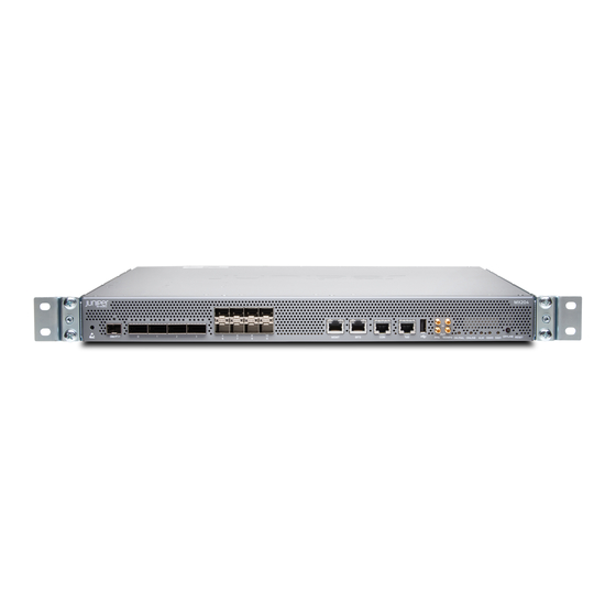
Step 4: Connect External Devices and Cables Figure 13 on page 11 shows the front panel of the MX204 router. All the connections to the router are made through the front panel. Figure 13: MX204 Front Panel Ports, LEDs, and Button 1—... -
Page 12: Connect The Router To A Network For Out-Of-Band Management
MGMT Plug the other end of the cable into the network device. Figure 14: Out-of-Band Management Cable Connector Table 2: Out-of-Band Management Port on the MX204 Router Callout Label Description Dedicated management channel for MGMT device maintenance. - Page 13 Parity—N Data bits—8 Stop bits—1 Flow control—none Figure 15: Console and Auxiliary Cable Connector Figure 16: Connecting the MX204 Router to a Management Console Through a Console Server To Console port Console server Figure 17: Connecting the MX204 Router Directly to a Management...
-
Page 14: Connect The Router To External Clocking And Timing Devices
Ensure that the 10-MHz or 1-PPS source network equipment contains low voltage complementary metal oxide semiconductor (LVCMOS) or is compatible with low-voltage (3.3 V) transistor–transistor logic (LVTTL). Table 4: Clocking Port on the MX204 Router Callout Label Description GPS input and output ports. -
Page 15: Connect A Bits External Clocking Device To The Router
The power supplies are hot-insertable and are field-replaceable units (FRUs). MX204 supports two power supply modules. The power supplies install in the rear of the chassis in the slots provided. -
Page 16: Connect Power To An Ac Router
Do not mix AC and DC power supplies in the same chassis. Connect Power to an AC Router on page 16 Connect Power to a DC Router on page 17 Connect Power to an AC Router Table 7: MX204 AC Power System Input Voltage Item Specification AC input voltage Operating range: 90–264 VAC... -
Page 17: Connect Power To A Dc Router
If the status LED indicates that the power supply is not functioning normally, repeat the installation and cabling procedures. Figure 18: Connecting an AC Power Cord to an MX204 AC Power Supply Connect Power to a DC Router Table 8: MX204 DC Power System Input Voltage... - Page 18 MX204 3D Universal Edge Router Quick Start The cable with very low resistance (indicating a closed circuit) to chassis ground is Remove the screws from the terminals. Secure each power cable lug to the terminal with the screw (see Figure 19 on page 19).
-
Page 19: Step 6: Perform Initial Software Configuration
If the status LED indicates that the power supply is not functioning normally, repeat the installation and cabling procedures. Figure 19: Connecting a DC Power Cable to an MX204 DC Power Supply Step 6: Perform Initial Software Configuration This procedure connects the router to the network but does not enable it to forward traffic. -
Page 20: Configure User Accounts And Passwords
MX204 3D Universal Edge Router Quick Start Configure User Accounts and Passwords For information about using an encrypted password or an SSH public key string (DSA or RSA), see Configuring the Root Password and authentication (Login) in the User Access and Authentication Feature Guide for Routing Devices. -
Page 21: Commit The Configuration
(Optional) Configure additional properties by adding the necessary configuration statements. Then commit the changes to activate them on the router. [edit] root@host# commit When you have finished configuring the router, exit configuration mode. Copyright © 2018, Juniper Networks, Inc. -
Page 22: Safety Warnings
Use an external surge protective device (SPD) at the AC input of the router. Only trained and qualified personnel must install or replace the router. Perform only the procedures described in this quick start or the MX204 3D Universal Edge Router Hardware Guide at . Other services should http://www.juniper.net/techpubs/... - Page 23 Manually installing the router requires two people for an empty chassis and three people for a fully configured router to lift the chassis. Before lifting the chassis with only two people, remove the components as described in the MX204 3D Universal Edge Router Hardware Guide at .
-
Page 24: Compliance Statements For Nebs
MX204 3D Universal Edge Router Quick Start Compliance Statements for NEBS The equipment is suitable for installation as part of the Common Bonding Network (CBN). The equipment is suitable for installation in locations where the National Electrical Code (NEC) applies. -
Page 25: Japan
Junos OS Release Notes. ® To obtain the most current version of all Juniper Networks technical documentation, see the product documentation page on the Juniper Networks website at http://www.juniper.net/techpubs/ Requesting Technical Support Technical product support is available through the Juniper Networks Technical Assistance Center (JTAC). -
Page 26: Self-Help Online Tools And Resources
Copyright © 2018 Juniper Networks, Inc. All rights reserved. Juniper Networks, the Juniper Networks logo, Juniper, and Junos are registered trademarks of Juniper Networks, Inc. and/or its affiliates in the United States and other countries. All other trademarks may be property of their respective owners.
Need help?
Do you have a question about the MX204 and is the answer not in the manual?
Questions and answers